method on-6 determination of odour … · stationary sources. ... the ontario source testing code...
TRANSCRIPT
Ontario Ministry of the Environment 1 July 2009
DRAFT
METHOD ON-6
DETERMINATION OF ODOUR EMISSIONS FROM STATIONARY SOURCES
as excerpted from Part G of the
ONTARIO SOURCE TESTING CODE
(VERSION # 3)
Standards Development Branch Ontario Ministry of the Environment
June 2009
Cette publication technique n'est disponible qu'en anglais.
Copyright: Queen's Printer for Ontario, 2009 This publication may be reproduced for non-commercial purposes
with appropriate attribution.

(This page intentionally left blank)
Ontario Ministry of the Environment ii June 2009
Preface
The information provided in this document is based on field experience and existing
practices and aimed at providing consistency in the emission measurements from
stationary sources. This document provides a set of guidelines and required
methodologies for the measurement of emissions of air contaminants from stationary
sources when such emissions are required for the purpose of determining compliance
with the Environmental Protection Act and the Regulations thereunder. Where a
Director may exercise discretion relating to the measurement of emissions of air
contaminants from stationary sources, this guideline sets out minimum expected
standards that the Director will apply in exercising his or her discretion in considering
each situation on a case-by-case basis.
Readers may reproduce any part of this Code for non-commercial purposes with
appropriate attribution. Copies may be obtained from the Internet at www.gov.ene.on.ca
under “Publications”.
While every effort has been made to ensure the accuracy of the information contained
in this Code, it should not be construed as legal advice. In the event of conflict with
requirements identified in the Regulation, which is being referenced, then the regulatory
requirements shall determine the appropriate approach.
Note: Mention of trade names or commercial products does not constitute
endorsement for use by the Ontario Ministry of the Environment.
Ontario Ministry of the Environment iii June 2009
Acknowledgements
This document has been prepared by the working group on Source Testing which was
composed of representatives of the Standards Development Branch, Ontario Ministry of
the Environment. We appreciate the comments provided by environmental consulting
organizations in Ontario as well as input from the Operations Division in the Ministry.

Ontario Ministry of the Environment 1 June 2009
OSTC Introduction
The Ontario Source Testing Code (OSTC) specifies methods and procedures for the
measurement of emissions of air contaminants (pollutants) from stationary sources
when such emission data are required for the purpose of determining compliance with
the Environmental Protection Act of the Province of Ontario and the regulations
thereunder. Strict adherence to the procedures described and reference methods listed
is required to eliminate the possibility of a test being rejected by the Ministry of the
Environment due to variations from the procedures described in this Code.
For the purpose of this Code:
(i) "Ministry" means the Ontario Ministry of the Environment;
(ii) "Director" means any Ministry employee appointed by the Minister pursuant
to Section 5 of the Environmental Protection Act, and acting within the
designated Region where source testing is being conducted;
(iii) "Provincial Officer" means the Provincial Officer as defined by the
Environmental Protection Act; and,
(iv) "Source Assessment Specialist" means a Ministry specialist in source
testing procedures from the Standards Development Branch, Technology
Standards Section.
This Code was developed to provide consistency in emission measurements from
stacks, ducts and area sources in order to accurately estimate emissions from the
source. The Code is intended to provide accuracy, consistency, uniformity and
compatibility in stationary source emission measurements among industry users and
source testing consultants. This Code applies only to emission measurements from
stationary sources that have batch, cyclic or continuous processes.
It will also provide guidance to industry, consultants and Ministry staff when conducting
emission testing survey(s) related to the development of emission factor(s) for unique
processes and assessing emissions for use in emissions inventories and Emission
OSTC OSTC Introduction 2
Ontario Ministry of the Environment June 2009
Summary and Dispersion Modelling (ESDM) reports completed in support of Ontario
Regulation 419/05 (O. Reg. 419/05).
It should be noted that in cases where a Director may exercise discretion with respect to
measurements of emissions of air contaminants from stationary sources, to the extent
that this document sets out that something is “required” or “shall” be done or sets out a
“requirement”, it does so only to identify minimum expected standards the application of
which remain subject to the discretion of the Director.
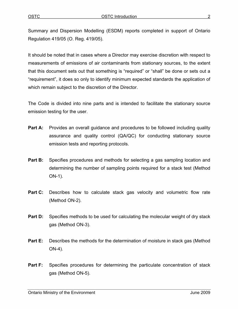
The Code is divided into nine parts and is intended to facilitate the stationary source
emission testing for the user.
Part A: Provides an overall guidance and procedures to be followed including quality
assurance and quality control (QA/QC) for conducting stationary source
emission tests and reporting protocols.
Part B: Specifies procedures and methods for selecting a gas sampling location and
determining the number of sampling points required for a stack test (Method
ON-1).
Part C: Describes how to calculate stack gas velocity and volumetric flow rate
(Method ON-2).
Part D: Specifies methods to be used for calculating the molecular weight of dry stack
gas (Method ON-3).
Part E: Describes the methods for the determination of moisture in stack gas (Method
ON-4).
Part F: Specifies procedures for determining the particulate concentration of stack
gas (Method ON-5).
OSTC OSTC Introduction 3
Ontario Ministry of the Environment June 2009
Part G: Specifies procedures for determining odour emissions from stationary
sources (Method ON-6).
Part H: Specifies procedures for determining the particulate matter size distribution of
stack gas (Method ON-7).
Attachments: The attachments include a listing of all reference source testing
methods and a guidebook to prepare a pre-test plan document.
OSTC Part G: Method ON-6 G -1
Ontario Ministry of the Environment June 2009
Part G Method ON-6: Determination of Odour Emissions from
Stationary Sources
TABLE OF CONTENTS
PAGE
Preface ........................................................................................................................... ii Acknowledgements...................................................................................................... iii OSTC Introduction ....................................................................................................... 1
1. Introduction ......................................................................................................... G-3
2. Purpose............................................................................................................... G-3
3. Limitations ........................................................................................................... G-4
4. Definitions ........................................................................................................... G-4
5. Dynamic Pre-Dilution Sampling........................................................................... G-6
5.1 Apparatus ...................................................................................................... G-7
5.2 Preparation .................................................................................................... G-9
5.3 Volumetric Flow Rate Determination............................................................ G-10
5.4 Pre-Dilution Ratio Determination ................................................................ G-11
5.5 Sampling Procedure (Non-Stratified Gas Stream) ....................................... G-16
5.6 Sample Recovery ........................................................................................ G-17
6. Undiluted - Evacuated Lung Sampling Procedure ............................................ G-18
6.1 Apparatus .................................................................................................... G-18
6.2 Preparation .................................................................................................. G-19
6.3 Volumetric Flow Rate Determination............................................................ G-19
6.4 Sample Procedure ....................................................................................... G-19
6.5 Sample Recovery......................................................................................... G-20
OSTC Part G: Method ON-6 G -2
Ontario Ministry of the Environment June 2009
TABLE OF CONTENTS, continued PAGE
7. Area Source – Flux Chamber Sampling Procedure .......................................... G-20
7.1 Apparatus .................................................................................................... G-21
7.2 Preparation .................................................................................................. G-22
7.3 Sample Procedure ....................................................................................... G-22
7.4 Sample Recovery......................................................................................... G-24
8. Open Bed Biofilter Sampling Method ................................................................ G-24
8.1 Sampling...................................................................................................... G-25
9. Odour Evaluation .............................................................................................. G-26
10. Appendices to Method ON-6 ............................................................................. G-26
10.1 Appendix 6A: Hydrocarbon Calibration Method – Calibrating Pre-
Dilution Sampling Apparatus ............................................................... G-26
10.2 Appendix 6B: Equations and Sample Calculations .................................... G-27
10.3 Appendix 6C: Conditional Odour Sampling Methods ................................. G-30
11. References........................................................................................................ G-34
Tables ....................................................................................................................... G-36
Figures ...................................................................................................................... G-39
OSTC Part G: Method ON-6 G -3
Ontario Ministry of the Environment June 2009
1. INTRODUCTION
This chapter outlines three traditional methods of sampling for odours (dynamic pre-
dilution, evacuated lung and flux chamber methods) and one modified method specific
to sampling open bed biofilters. Assessors must choose the most appropriate sampling
method based on a preliminary assessment of each individual source. Certain source
parameters may dictate that a non-traditional method may be required to ensure
accurate, representative data. Several non-traditional methods that have been
successfully applied in the past are outlined in the appendix of this chapter. When
developing and/or using a non-traditional method, it is necessary that the Source
Assessment Specialist be contacted to discuss sampling strategies.
Methods for quantifying fugitive odour concentrations and emission rates have not been
outlined in this document. Fugitive odours can be a major contributor to a facility’s
aggregate odour impact; as such, these emissions are required to be addressed. The
unique nature of facilities and the way in which fugitive odours may be emitted requires
that the sampling strategy for sampling fugitive odour emissions be dealt with on an
individual basis.
2. PURPOSE
This method is intended to determine the odour concentration of undefined mixtures of
gaseous odorants of a gas stream in a stack, duct and area source. The samples are
collected by dynamic dilution with neutral gas, undiluted by evacuated lung, or via flux
chamber sampling procedures and are evaluated using dynamic olfactometry with a
panel of human assessors (odour panel evaluation technique).
OSTC Part G: Method ON-6 G -4
Ontario Ministry of the Environment June 2009
3. LIMITATIONS
The methodology outlined within this chapter is not applicable to measuring odours from
solid odour emitting particles or droplets of odorous fluids within a “supersaturated” gas
stream. The Source Assessment Specialist should be contact to discuss sample
strategies when it is deemed that a customized (non-traditional) sampling strategy is
necessary.
4. DEFINITIONS
Listed in this chapter are the more frequently referenced definitions. For a complete list
of definitions, refer to the European Standard EN 13725: 2003 (Determination of Odour
Concentration by Dynamic Olfactometry) or its more recent version.
Detection threshold (Sample) Dilution factor at which the sample has a 50%
probability of being detected by a human
assessor.
Dilution factor The ratio between sample flow or volume
after dilution (Total Sample Volume) and the
flow or volume of the odorous gas
(“Undiluted” Sample Volume).
Dynamic dilution Dilution achieved by mixing two known flows
of gas; odorous sample and neutral gas,
respectively. The rate of dilution is calculated
from the flow rates.
Flux Chamber A device used to isolate a surface area for
collecting gaseous emissions being
generated as neutral gas is being passed
over the enclosed area.
OSTC Part G: Method ON-6 G -5
Ontario Ministry of the Environment June 2009
Maximum dilution factor Maximum achievable dilution factor of the
olfactometer; an instrument property.
Minimum dilution factor Minimum achievable dilution factor of the
olfactometer; an instrument property.
Neutral gas (diluent) Air or nitrogen that is treated in such a way
that it is as odourless as technically possible
(nitrogen of 4.8 Grade or higher is
recommended) and that does, according to
panel members, not interfere with the odour
under investigation.
SAFETY WARNING: Nitrogen is only used to
predilute the sample itself. For the
olfactometer, the neutral gas which is used to
dilute the sample and present a reference
shall be air.
Odour emission rate The quantity of odour units (ou) which
crosses a given surface divided by time. It is
the product of the odour concentration Cod,
and the wet reference volumetric flow rate (at
standard temperature and standard
atmospheric pressure, 298 K and 101.3 kPa
respectively). It is typically expressed as
ou/s.
Odour concentration Number of odour units per volume of gas at
wet standard conditions. . It is typically
expressed as ou/m3.
OSTC Part G: Method ON-6 G -6
Ontario Ministry of the Environment June 2009
Odour unit One odour unit is the amount of (a mixture of)
odorants present in one cubic metre of
odourous gas (under standard conditions) ath
the panel threshold.
Pre-Dilution Drawing a sample of stack gas while
simultaneously diluting it with neutral gas for
the purpose of preventing condensation
and/or adsorption of odours upon sample
collection and to reduce sample gas
temperature.
Sample The amount of gas which is assumed to be
representative of the gas mass or gas flow
under investigation and which is examined for
odour concentration.
Standard Conditions for Olfactometry Room temperature (293 K) and normal
atmospheric pressure on a wet basis.
Sweep gas Neutral gas which is introduced at a low
velocity into a flux chamber.
5. DYNAMIC PRE-DILUTION SAMPLING
Source parameters may result in the necessity to “pre-dilute” a sample prior to collection
in a sample container. In all cases pre-dilution of stack gas is required if:
1. It is determined that the stack gas temperature may degrade the sample
container;
2. The moisture content of the stack gas will result in condensation forming in the
sample container;

OSTC Part G: Method ON-6 G -7
Ontario Ministry of the Environment June 2009
3. It is determined that the odour intensity is great enough that it is likely to result
in a positive response at the highest dilution factor of the olfactometer.
The Source Assessment Specialist may also require pre-dilution sampling if it is
determined that the stack gas characteristics suggest a high probability of “plating” or
adsorption of odorous compounds to the walls of the sample container.
5.1 Apparatus
The odour sample collection system must be capable of dynamically pre-diluting
the stack gas with odour free purified nitrogen. The quantity of nitrogen shall be
sufficient to prevent condensation and/or adsorption of odours, and hydrocarbons
upon sample collection and cooling to ambient temperatures (~21°C).
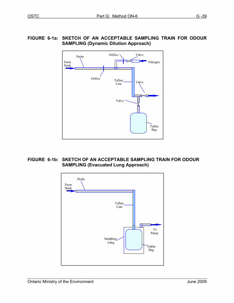
A sketch of an acceptable dynamic pre-dilution odour sample collection system is
shown in Figure 6-1a. Other odour sample collection systems may be used,
provided it can be demonstrated that they are effective in preventing condensation
and/or absorption upon sample collection and cooling to ambient temperature.
(a) Probe – structurally stable stainless steel, Teflon®, borosilicate or quartz
glass. The distance between the probe and the sample container shall be
kept to a minimum.
(b) Velocity & Flow Measurement Device – with a resolution of 0.01 m/s such
as an anemometer or pitot-tube; reference should be made to Method ON-
2 concerning pitot tube configuration and calibration.
(c) Temperature Sensor – thermocouple or other calibrated device capable of
measuring stack gas temperature to within 1.5% of the minimum
temperature; sensor must be checked according to the procedure outlined
on Method ON-2 (Chapter 7.5, Appendix 2E).
(d) Differential Pressure Gauges – to use with Pitot tube and orifice meter.
Inclined manometer or devices of equivalent sensitivity, readable to the
OSTC Part G: Method ON-6 G -8
Ontario Ministry of the Environment June 2009
nearest 0.10 mm water column for differential pressure (∆P) values
between 0.10 mm and 25 mm WC, and readable to the nearest 1.3 mm
WC for ∆P values greater than 25 mm WC; a more sensitive unit will be
required if a ∆P reading is found to be less than 5 smallest scale divisions,
see Method ON-2 (Chapter 7.3, Appendix 2C).
(e) Sample Line – made of Teflon®, stainless steel or glass; the distance
between the probe and the sample container shall be kept to a minimum.
All fittings shall be clean and odour free and preferably of Telfon® or
stainless steel composition.
(f) Sample Containers – material of construction shall be Tedlar®, Teflon® or
any other materials (such as Nalophane®) which will not compromise the
integrity of the sample. When such other materials are proposed,
approval from the Source Assessment Specialist is required. The sample
container shall be of sufficient volume to carry out a minimum of an eight
member odour panel evaluation.
(g) Heated Sample Box – a heated enclosure (or heated probe assembly)
shall be used to maintain the temperature of the stack gas, up to a
maximum temperature of 120ºC, from the point at which it is drawn from
the stack, to the point when it has been diluted with pre-purified nitrogen.
Maintaining the sample gas stream at the stack temperature prevents the
formation of condensation within the sample apparatus prior to the point of
dilution.
(h) Valves – capable of metering the dilution air flow and the sample flow;
material of construction shall be Teflon®, glass or stainless steel.
(i) Orifice Meters – capable of accurately measuring the flow ranges required
for pre-dilution flow, sample flow and total flow. The material of
OSTC Part G: Method ON-6 G -9
Ontario Ministry of the Environment June 2009
construction shall be glass, Teflon® or stainless steel.
(j) Pre-Dilution Odourless Gas – nitrogen (4.8 grade or higher).
5.2 Preparation
1) The Pitot tube and orifice meters must be maintained in accordance with
the standard accepted procedures and calibrated prior to testing, in
accordance with Method ON-2 (Chapter 7.1, Appendix 2A) and Method
ON-4 (Chapter 6.2, Appendix 4B). The orifices shall be calibrated in the
flow ranges required for the tests.
2) The probe and the sample transfer line must be clean and free of residual
odour. If any contamination is observed on the sample transfer line, the
sample transfer line must be replaced. A new and/or clean odour free
sample line should be used for each source being measured.
3) The sample containers shall be preconditioned by heating to 70°C
(158°F), and flushed continuously with odourless air for a minimum of
24 hours. Note that materials other than Tedlar® and Telfon® may not
require such preconditioning. However, guidance in this issue is required
from the Source Assessment Specialist.
4) The sampling site or location must be selected in accordance with Method
ON-1.
5) The odour collection system must be calibrated for its complete range of
pre-dilution ratios, across the units’ range of operating temperature, using
a tracer gas and a flame ionization detector (FID). This calibration shall be
completed at a minimum frequency of 6 months (see Hydrocarbon
Calibration procedure in Chapter 10.1, Appendix 6A). Prior to utilizing
equipment in the field, complete flow checks on each sample collection
system and compare the results to data collected during most recent
OSTC Part G: Method ON-6 G -10
Ontario Ministry of the Environment June 2009
tracer gas calibration. Anomalies shall be flagged and the system shelved
until it is recalibrated.
All calibration data must be available on request prior to or during the
actual testing, and must be submitted with the final report.
6) The odour sampling collection system must be leak-checked prior to
mobilization to ensure sample integrity and is performed according to the
following procedure:
Odour Sampling Leak-Check
6a) Plug both the inlet to the probe and the dilution gas inlet.
6b) Using a metering system comprised of a vacuum gauge, leak-free
pump, and a calibrated dry gas meter draw a vacuum of 380 mm Hg.
6c) Maintain the vacuum for at least 1 minute. A leakage rate of 4% of
the undiluted sample flow or greater is unacceptable and if found, the
sampling train should be dismantled and reassembled until the leak
is adequately reduced or eliminated.
5.3 Volumetric Flow Rate Determination
Volumetric flow rate must be determined in accordance with Method ON-2, which
necessitates molecular weight and stack gas moisture determination, via Method
ON-3 and ON-4 respectively.
The exhaust gas stream shall be checked for stratification based on O2
concentrations measured at nine points across a single traverse. The flow in the
stack or duct is considered to be stratified if the % stratification calculated exceeds
10% (see Equation 6-1, Chapter 10.2, Appendix 6B). If a repeat measurement at
any given point results in the concentration differing by more than ±10%,
stratification must be retested during more stable conditions. Please see the
chapter titled “Stratification Test Procedure” in Environment Canada’s Report
OSTC Part G: Method ON-6 G -11
Ontario Ministry of the Environment June 2009
EPS 1/PG/7, December 2005 (or the most recent version) if further guidance is
required.
If stack gas stratification is identified, contact the Source Assessment
Specialist to discuss the most appropriate strategy for sample collection.
5.4 Pre-Dilution Ratio Determination
The odour sample is “pre-diluted” with odourless gas (nitrogen) during sampling to
prevent condensation and/or absorption of odours and hydrocarbons upon sample
collection and cooling to ambient temperature; therefore, preliminary tests must be
carried out at the source(s) to determine the required pre-dilution ratio.
When an odour sample is collected from a source that exhausts gas containing
water vapour, there is the potential for this water vapour to condense. The
condensed water, called dew has the potential to adsorb odorous compounds in
the sample gas and negatively bias the odour analysis results.
The sample “dew point” is the temperature at which the gaseous sample becomes
saturated with water vapor. If the sample temperature is maintained at a level
higher than the dew point temperature; water vapour remains gaseous. If the
sample cools to a temperature below the dew point, water vapor will condense and
the odour sample is deemed invalid. Pre-diluting the gas sample with dry nitrogen
will lower the total moisture content in the sample container, therefore lowering the
dew point temperature. This procedure is used to avoid the formation of
condensation which can occur as the sample gas cools after being extracted from
the exhausts gas stream.
The following procedure defines the method for calculating the pre-dilution ratio
(dry nitrogen to stack gas) necessary to prevent the formation of condensation in a
sample container and is based on the measured stack gas moisture content and
the lowest temperature at which the gaseous sample is expected to reach during
transport and analysis.
OSTC Part G: Method ON-6 G -12
Ontario Ministry of the Environment June 2009
5.4.1 Procedure for Calculation of the Pre-Dilution Ratio
1) Determine the stack gas moisture content following the procedures
outlined in Part E, Method ON-4. Record the sample volume (m³ of dry
exhaust gas) and total condensed moisture collected (mL or g) and
calculate the moisture content in g/m³.
2) Determine the lowest temperature that the sample gas will reach during
transport and/or analysis (i.e. ambient temperature or the odour
evaluation laboratory temperature), and record the temperature of the
exhaust gas.
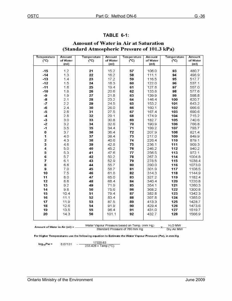
3) From Table 6-1 obtain the amount of water in air (g/m3), assuming 100%
relative humidity, for the ambient temperature or the expected
temperature of the odour evaluation laboratory; which ever is lower.
4) If the total condensed moisture per cubic metre obtained in Step 1 (g/m3)
exceeds that obtained in Step 3 (g/m3) sample pre-dilution is required.
Note: for supersaturated gas streams, it is necessary to use the
actual water condensate volume collected;
5) To determine the pre-dilution ratio, divide the measured stack gas
moisture content (g/m3) from Step 1 by the amount of water in air at the
dew point temperature selected in Step 3.
For example, if the stack gas moisture content is measured to be 45
g/m3 and the lowest temperature the sample will reach is defined as the
laboratory temperature (21°C); based on Table 6-1 the stack gas sample
must be diluted to contain a maximum of 15 g of water per cubic metre
of air to prevent condensation. By dividing the stack gas moisture
condensate of 45 g/m3 by the water content at the selected dew point
OSTC Part G: Method ON-6 G -13
Ontario Ministry of the Environment June 2009
temperature (15 g/m3), the dilution ratio required to prevent
condensation is estimated at 3 volumes of nitrogen by 1 volume of
exhaust gas sample.
6) The pre-dilution ratio used in the field shall be a maximum of 20% higher
than that calculated based on this methodology. For low level pre-
dilution (less than 10:1) this criteria does not apply; the closest
achievable dilution setting can be used assuming that it is no higher than
10:1. A dilution level lower than that calculated shall not be used, as it is
likely to result in the formation of condensation.
7) In cases when the odour concentration is so high that panelists will make
a positive identification even if the olfactometer is diluting the odour
sample in its upper dilution range, the odour assessment results are
rejected as inconclusive. A new set of samples need to be collected from
the source, making sure that a suitable pre-dilution ratio is selected that
will accommodate the minimum number of dilution step presentations
required by the odour evaluation facility. As a result, the calculated pre-
dilution ratio may be increased with prior approval from the Source
Assessment Specialist.
5.4.2 Alternate Methods for the Determination of the Optimum Pre-
Dilution Rates
The following procedures may be used to determine the dew point of odour
samples for the purposes of setting pre-dilution rates. They can be used in lieu
of Method ON-4’s moisture determination, if stack gas temperature is less than
100°C, and the gas stream does not contain water droplets.
5.4.2.1 Relative Humidity
The relative humidity is the ratio of the actual water vapour pressure to the
saturation water vapour pressure (100% humidity) at a selected
OSTC Part G: Method ON-6 G -14
Ontario Ministry of the Environment June 2009
temperature. Using a commercially available electronic sensor relative
humidity can be easily measured.
In order to use relative humidity measurements for pre-dilution ratio
determination, the following steps are required:
1) Using an electronic sensor measure the relative humidity of the stack
gas (following the manufacturer’s instructions).
2) Measure the stack gas temperature, Ts (refer to Method ON-2).
3) From Table 6-1 obtain the amount of water in air (g/m3), assuming
100% relative humidity, at the stack gas temperature.
4) Multiply the water in air value (obtained from Step 3) by the percent
relative humidity (obtained from Step 1). This will determine the
stack gas moisture content (g/m3).
5) From Table 6-1 obtain the amount of water in air (g/m³), assuming
100% relative humidity, for the ambient temperature or the expected
temperature of the odour evaluation laboratory; which ever is lower.
6) If the total condensed moisture per cubic metre obtained in Step 4
(g/m3) exceeds that obtained in Step 5 (g/m3) sample pre-dilution is
required.
7) Follow Steps 5 to 7 of the pre-dilution determination procedure
(Chapter 5.4.1) to calculate the required dilution rate.
5.4.2.2 Water Vapour Pressure
In order to use the water vapour pressure for pre-dilution determination, the
following steps are required:
1) Measure the stack gas temperature, Ts (refer to Method ON-2).
OSTC Part G: Method ON-6 G -15
Ontario Ministry of the Environment June 2009
2) Measure the stack gas pressure, Ps (refer to Method ON-2).
3) Based on the stack gas temperature, obtain the water vapour
pressure.
4) Divide the water vapour pressure obtained by the static pressure of
the stack gas.
5) Multiply the water vapour pressure to stack gas pressure ratio
(obtained from Step 4) by the water vapour molar mass (0.018 kg),
and then divide this result by the molar mass of dry air (0.029 kg).
6) From Table 6.2 obtain the volume of water in air (g/m3), assuming
100% relative humidity, for the ambient temperature or the expected
temperature of the odour evaluation laboratory; which ever is lower.
7) If the total condensed moisture per cubic metre obtained in Step 5
(g/m3) exceeds that obtained in Step 6 (g/m3) sample pre-dilution is
required.
8) Follow Steps 5 to 7 of the pre-dilution determination procedure
(Chapter 5.4.1) to calculate the required dilution rate.
5.4.2.3 Psychrometer (Wet and Dry Bulb Thermometer)
Wet and dry bulb thermometer technique can be used if:
(i) stack gas temperature is less than 100°C;
(ii) the gas stream velocity is greater than 5 m/s; and
(iii) the gas stream does not contain water droplets or acid mist.
In order to use the wet and dry bulb thermometer technique, for pre-dilution
determination, the following steps are required:
OSTC Part G: Method ON-6 G -16
Ontario Ministry of the Environment June 2009
1) Measure the dry stack gas temperature (refer to Method ON-2).
2) Simultaneously measure the wet bulb stack gas temperature.
3) Based on the stack gas wet and dry bulb temperatures, use a
psychrometric chart to determine the volume of water vapour in the
stack gas.
4) From Table 6-1 obtain the volume of water in air (g/m3), assuming
100% relative humidity, for the ambient temperature or the expected
temperature of the odour evaluation laboratory; which ever is lower.
5) If the total condensed moisture per cubic metre obtained in Step 3
(g/m3) exceeds that obtained in Step 4 (g/m3) sample pre-dilution is
required.
6) Follow Steps 5 to 7 of the pre-dilution determination procedure
(Chapter 5.4.1) to calculate the required dilution rate.
The results of the pre-dilution ratio determination must be made available upon
request during collection of the “optimum dilution” ratio samples and shall be
included in the final report.
If uncertain on what approach to use to determine the “optimum dilution” ratio, the
Ministry’s Source Assessment Specialists need to be contacted for guidance.
5.5 Sampling Procedure (Non-Stratified Gas Stream)
1) Assemble the odour sample collection system. Place the probe at a single
point near the centre of the stack or duct. If the stack or duct exceeds 2.0 m
in diameter, the sample probe can be place at any single point, greater than
1.0 m away from the stack or duct wall.
OSTC Part G: Method ON-6 G -17
Ontario Ministry of the Environment June 2009
2) Ensure that all sample ports, including the area around the sample probe,
are covered to prevent the dilution of the gas stream.
3) Heat the front end of the sample apparatus (between the stack and the point
of dilution) to the temperature of the stack gas (±20%), or 120ºC; whichever
is lower, for the purpose of preventing the formation of condensation in the
sample line prior to being diluted with nitrogen.
4) To condition the sample container, start the flow of nitrogen and adjust the
stack gas sample flow rate to obtain the proper predetermined pre-dilution
ratio. Fill the sample container with the pre-diluted stack gas, and then
empty the sample container. Repeat the procedure. The sample container
is now conditioned for the collection of an odour sample.
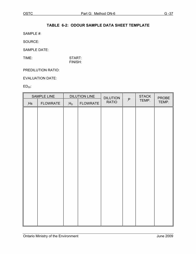
5) Adjust the sample flow rate such that the sample container is filled over a 10
minute sampling period. Connect the sample container, obtain sample and
record all data according to Table 6-2.
6) The operator must watch over the sampling trains flow/pressure measuring
device(s) throughout the entire test period to ensure a consistent pre-
dilution rate is being achieved for the duration of the test.
7) A minimum of three separate samples shall be collected, at the optimum
dilution rate, from each source.
5.6 Sample Recovery
After completion of the ten (10) minute sample collection, the sample container is
immediately sealed, labelled and shielded from direct sunlight. To protect from
photo-chemical degradation samples shall be placed in a dark or opaque container
for storage and transport.
Samples shall be transported to an accredited odour analysis laboratory to be
OSTC Part G: Method ON-6 G -18
Ontario Ministry of the Environment June 2009
analyzed within 24 hours of sample collection.
Note: DO NOT use stickers, tapes or other adhesive/solvent based products to
label Tedlar® or Teflon® sample bags as there is the potential for odours to
migrate into the sample container.
6. UNDILUTED – EVACUATED LUNG SAMPLING PROCEDURE
In the case that stack temperatures and moisture content are low and if it is determined
that the stack gas odour concentration is within the dilution range of the olfactometer,
the evacuated lung sampling procedure may be utilized.
6.1 Apparatus
The odour sample collection system must be capable of drawing a sample at a
nominal rate of 1 litre per minute. A pump is used to evacuate a rigid leak-free
vessel creating negative pressure which draws a sample of stack gas from the gas
stream, through a sample probe, into a sample bag contained within the vessel.
A sketch of an acceptable evacuated lung odour sample collection system is
shown in Figure 6-1b. Other odour sample collection systems may be used,
provided it can be demonstrated that they are effective in obtaining a sample with
minimal possibility of contamination and can accurately dilute the sample.
(a) See Chapter 5.1 (a – f).
(b) Sample Lung – rigid vessel or container, capable of maintaining a
vacuum sufficient to pull the sample from the exhaust stream, within the
time required.
(c) Pump – Leak free Teflon® coated diaphragm-type pump (with adjustable
flow) or equivalent, which is capable of delivering at least 1 litre/minute.
OSTC Part G: Method ON-6 G -19
Ontario Ministry of the Environment June 2009
Note: When sampling a stack or duct with significant negative pressure,
a pump with a higher capability will be required.
(d) Flow meter - 0 to 5 litre flow range
6.2 Preparation
See Chapter 5.2 (Steps 1 to 4).
6.3 Volumetric Flow Rate Determination
See Chapter 5.3.
6.4 Sample Procedure
1) Assemble the odour sample collection system. Place the probe at a single
point near the centre of the stack or duct. If the stack or duct exceeds 2.0 m
in diameter, the sample probe can be place at any single point, greater than
1.0 m away from the stack or duct wall.
2) Ensure that all sample ports, including the area around the sample probe,
are covered to prevent the dilution of the gas stream.
3) To condition the sample container, connect the sample container to the
sample line, seal the rigid vessel and start the pump. Fill the sample
container with the stack gas. Empty the sample container and repeat the
above procedure. The sample container is now conditioned for the
collection of odour samples.
4) Reconnect the conditioned sample container, seal the rigid vessel and begin
sampling by starting the pump; adjusting the sample flow rate such that the
sample container is filled over a 10 minute sampling period. Record all data
according to Table 6-2.
5) If sampling a gas stream of negative static pressure, it is important to
OSTC Part G: Method ON-6 G -20
Ontario Ministry of the Environment June 2009
remove and seal the sample container immediately following sample
collection to ensure the sample is not drawn back into the stack or duct.
When sampling a stack or duct with a high negative pressure it may be
necessary to incorporate a clean odour free stainless steel needle valve
between the sample probe and sample container. This valve can be closed
immediately following sample collection to prevent sample loss.
6) A minimum of three separate samples shall be collected from each source.
6.5 Sample Recovery
See Chapter 5.6.
7. AREA SOURCE – FLUX CHAMBER SAMPLING PROCEDURE
This method is applicable to sampling for odours from area sources with no induced
flow, including but not limited to: waste water lagoons, sewage treatment settling
tanks/clarifiers, landfills and compost piles. This method is not applicable to open bed
biofilters.
Area sources are rarely homogeneous in nature. As a result, it is important that a well
developed sampling strategy is employed to ensure that the samples collected provide
a fair representation of the odour emission potential of the source as a whole. This may
require sampling to be completed at multiple locations, for each individual source.
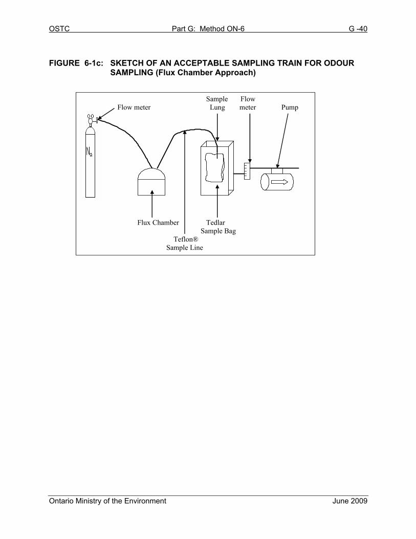
A sketch of an acceptable area source odour sample collection system is shown in
Figure 6-1c. Other odour sample collection systems and procedures may be used,
provided it can be demonstrated that they are suitable for their intended purpose and
have been approved by a Source Assessment Specialist.
Note that sampling, using this approach, is not to be conducted on rainy days (or when
rain occurs within 24 hours of the scheduled sampling); as the rain will interfere with the
OSTC Part G: Method ON-6 G -21
Ontario Ministry of the Environment June 2009
normal generation and release of the odorous emissions (odour scrubbing effect).
7.1 Apparatus
(a) Sample Line – made of Teflon®, or glass; the distance between the probe
and the sample container shall be kept to a minimum. All fittings shall be
clean and odour free and preferably of Telfon® or stainless steel
composition.
(b) Sample Containers – material of construction shall be Tedlar®, Teflon® or
any other materials (such as Nalophane) which will not compromise the
integrity of the sample. When such other materials are proposed,
approval from the Source Assessment Specialist is required. The sample
container shall be of sufficient volume to carry out a minimum of an eight
member odour panel evaluation.
(c) Sample Lung – rigid vessel or container, capable of maintaining a vacuum
sufficient to pull the sample from the exhaust stream, within the time
required.
(d) Pump – Leak free Teflon® coated diaphragm-type pump (with adjustable
flow) or equivalent, which is capable of delivering at least 1 litre/minute.
Note: When sampling a stack or duct with significant negative pressure, a
pump with a higher capability will be required.
(e) Flow meter – Two (2) flow meters with a 0 to 5 litre flow range.
(f) Odourless Gas – Nitrogen (4.8 grade or higher).
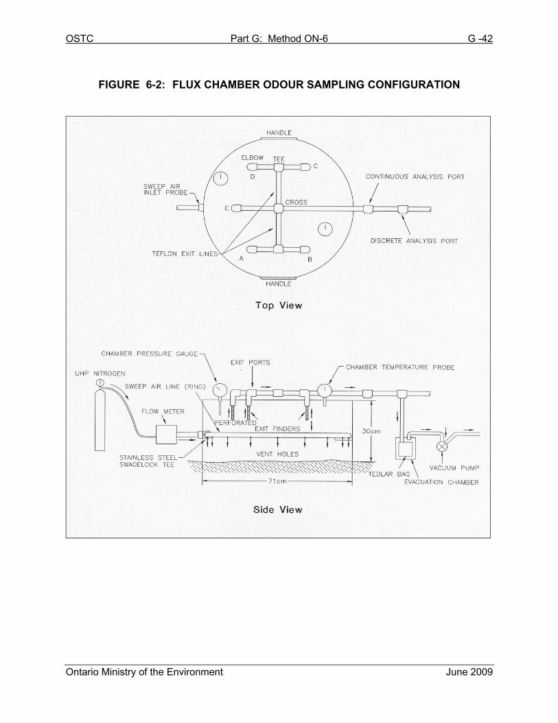
(g) Flux Chamber – Enclosure with a cylindrical shaped base and a spherical
top, constructed of stainless steel or plexiglass. The unit shall be equipped
with odour free fittings which will allow for the introduction of neutral
OSTC Part G: Method ON-6 G -22
Ontario Ministry of the Environment June 2009
(sweep) gas, the extraction of a gaseous sample and the relief of sweep
gas pressure (i.e. with a bleed valve). See Figure 6-2 for a diagram. The
flux chamber may be equipped with a floatation device for sampling liquid
surfaces.
7.2 Preparation
1) The sample containers shall be preconditioned by heating to 70°C (158°°F),
and flushed continuously with odourless air for a minimum of 24 hours.
Note that materials other than Tedlar® and Telfon® may not require such
preconditioning. However, guidance in this issue is required from the
Source Assessment Specialist.
2) The flux chamber shall be clean and free of residual odour prior to each
use.
3) The sample transfer line must be clean and free of residual odour. If any
contamination is observed on the sample transfer line, the sample transfer
line must be replaced. A new and/or clean odour free sample line should be
used for each source being measured.
7.3 Sample Procedure
1) Assemble the odour sample collection system and place the flux chamber
over the surface area to be tested. Ensure that the cylindrical walls of the
flux chamber are slightly below the sampling surface thereby preventing the
introduction of ambient air into the chamber.
2) Start the flow of metered sweep gas into the flux chamber. The flow rate
shall be metered at 0.00064 m3/s based on one square metre of coverage.
Using an EPA style flux chamber with a diameter of 40.6 cm and area
coverage of 0.13 m2, sweep gas flow rates shall be metered at 5L/min.
Flux chambers covering a larger surface area will require a higher sweep
OSTC Part G: Method ON-6 G -23
Ontario Ministry of the Environment June 2009
gas flow rate. In such cases, the sweep gas flow rate results will need to be
normalized to 0.00064 m3/s based on one square metre of coverage.
3) Allow a minimum of 4 air exchanges to occur within the chamber prior to
drawing a sample. Each air exchange represents passing a volume of
sweep gas into the flux chamber that is equal to the chamber volume.
4) To condition the sample container, connect it to the sample line within the
rigid vessel. Seal the vessel and start the pump. Fill the sample container
and stop the pump. Empty the sample container and repeat the above
procedure. The sample container is now conditioned for the collection of
odour samples.
5) Reconnect the conditioned sample container to the sample line within the
rigid vessel, seal the vessel and begin sampling by starting the pump. The
sample flow rate is required to be such that the sample container is filled
over a 10 minute sampling period. The sweep gas volumetric flow rate must
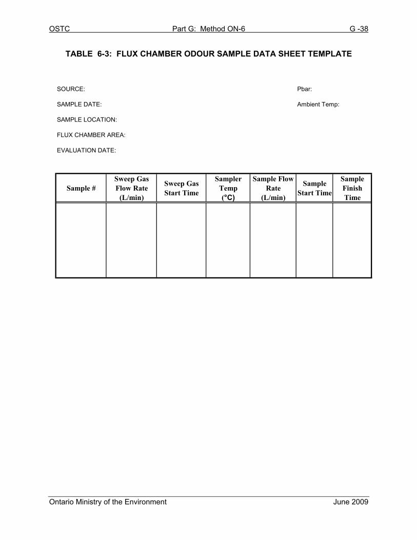
exceed that of the sample flow rate. Record all data according to Table 6-3.
6) A minimum of three separate samples shall be collected from each source;
but as indicated previously, area sources are rarely homogeneous in nature.
The number of separate samples may be higher than three; depending on
the number of selected locations that will provide a fair representation of the
odour emission potential, of the source as a whole.
Note that when using the flux chamber approach, for collecting odour samples, the
odour concentration is calculated based on the sweep gas rate; meaning that the
rate of odorourant released from the source may not be equivalent to the rate of
the flux chamber sweep gas.
The flux chamber sweep gas rate, and its normalization, is used for
convenience; as the rate of odourant release is very complicated to
OSTC Part G: Method ON-6 G -24
Ontario Ministry of the Environment June 2009
calculate. The rate of odorant release, from a surface area, will depend (among
other parameters) on the temperature of the surface, the porosity of the surface,
ambient relative humidity, the substance chemical and physical composition
releasing the odourant, the surface tension between the odourant and the surface
area, and the sweeping effect of the wind on the surface area.
7.4 Sample Recovery
See Chapter 5.6.
8. OPEN BED BIOFILTER SAMPLING METHOD
Open bed biofilters have characteristically low air flow velocities over a large surface
area. Typically, biofilters are designed with airflows ranging from 0.005 to 0.0025 m/s,
with a residence time of the gas exhaust (within the filter bed) ranging from 30 to
60 seconds, in most cases.
The presence of this induced flow differs significantly from the traditional stack, duct or
vent emissions. Although identified as an area source in dispersion models, the
biofilters fan induced flow makes sampling using area source odour sampling methods
(i.e flux chamber sampling) unsuitable. The following sampling method incorporates the
evacuated lung sampling apparatus with a passive capture system used to provide an
ideal sampling location, while causing minimal disturbance to the natural air flow of the
biofilter bed.
Other odour sample collection systems and procedures may be used, provided it can be
demonstrated that they are suitable for their intended purpose and have been approved
by a Source Assessment Specialist.
Note that sampling, using this approach, is not to be conducted on rainy days (or when
rain occurs within 24 hours of the scheduled sampling); as the rain will interfere with the
normal generation and release of the odorous emissions (odour scrubbing effect).

OSTC Part G: Method ON-6 G -25
Ontario Ministry of the Environment June 2009
8.1 Sampling
Odour sampling locations are established by conducting an initial airflow survey
over the surface area being assessed. This survey will reveal any airflow trends
over distance, preferential air flow, possible breakthrough zones, and relative
uniformity.
Once relative air velocity patterns have been mapped, it is possible to select
sampling locations representing typically average air flow zones. An area zone is
defined as an area where the flow is within 20% of the average flow velocity of all
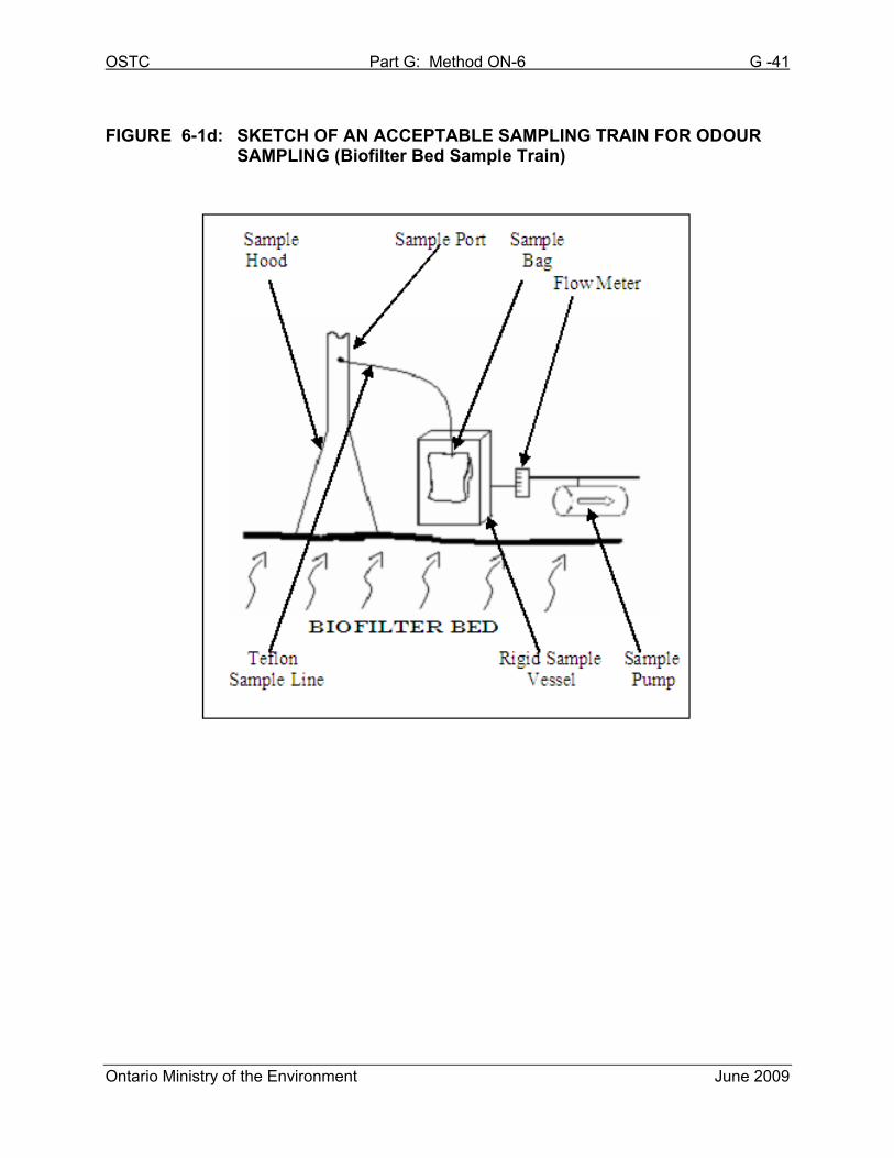
the velocity mapping points under consideration. Air velocity measurements are
taken using a sampling hood (inverted funnel) with a straight, open ended section
of duct work extending from the top (see Figure 6-1d).
It is imperative, when using this methodology that consideration be taken during
the design of the sampling hood and duct, to minimize the entry loss of the gas
confined in the hood when entering the duct. Typically, entry losses from the
transition area, between the hood and the duct, will vary depending on the angle of
entry. Based on a round hood with a height to duct diameter ratio of 3 to 1, the
entry loss will be negligible at and entry angle of 60°; but in the range of 40%
(velocity pressure loss) based on an angle of entry of 150°.
The differential pressure across the surface area of the biofilter bed, within the
sampling hood (created by poorly design sampling hood and duct system), has the
potential to alter the natural air flow of the bed; therefore, providing inaccurate non-
representative sampling results.
In addition, to the reduction of losses due to friction in the hood and duct; the duct
should be designed to be able to allow gas velocity reading as low as 0.015 m/s or
better. Velocity readings can accurately be measured, up to 0.015 m/s, by
commercially available air velocity meters.
OSTC Part G: Method ON-6 G -26
Ontario Ministry of the Environment June 2009
At least one sampling point per area zone is required. In instances where no
different area zones are identified, a minimum of three sampling locations are
spaced such that the full open area is represented.
At each sampling location, set up the sampling hood apparatus and measure
temperature humidity and velocity from the straight section of ductwork extending
from the top of the cone. Concurrently, use an evacuated lung sampling system to
obtain triplicate odour samples by pulling the emissions from the same area into a
Tedlar® bag (see Chapter 6). A pre-dilution sampler may be needed if high
moisture levels and/or very high odour concentrations are encountered (see
Chapter 5).
A sketch of this apparatus is shown in Figure 6-1d.
9. ODOUR EVALUATION
For the evaluation of odour concentrations of gaseous samples, refer to the
European Standard EN 13725: 2003 or its most recent version.
10. APPENDICES to METHOD ON-6
10.1 APPENDIX 6A: Hydrocarbon Calibration Method – Calibrating
Pre-Dilution Sampling Apparatus
1) Assemble the pre-dilution sampling apparatus without sample container or
sample lung.
2) Attach the sample inlet of the pre-dilution sampling apparatus probe to a
hydrocarbon source of known concentration, i.e., certified calibration gas
(Propane or Methane).
OSTC Part G: Method ON-6 G -27
Ontario Ministry of the Environment June 2009
Note: hydrocarbon concentration should be sufficiently high so as not to
exceed the detection limit of continuous analyzers equipped with a
flame ionization detector at the highest pre-dilution ratio anticipated
for the tests.
3) Assemble a continuous hydrocarbon analyzer (flame ionization detector) to
draw a slip stream from the pre-dilution apparatus sample collection outlet.
Hydrocarbon concentrations shall be recorded on a continuous basis (1
second intervals) and logged electronically via data acquisition system
across a range of dilution settings. The hydrocarbon analyzer and data
acquisition system shall be maintained and operated according the
manufacturer’s specifications and the analyzer shall meet the performance
criteria outlined in the US EPA 40CFR60 Method 25A.
4) Start the flow of neutral gas and adjust the sample apparatus to achieve the
desired pre-dilution ratio. Record the data according to Table 6-2, excluding
the stack temperature. Maintain this operation for a minimum of 2 minutes.
Record the undiluted hydrocarbon concentration on the data sheet and
calculate the actual dilution factor based on the analyzer readings for each
dilution setting. Readings obtained during the 2 minute interval should be
stable. Differences exceeding ±10% during the 2 minute reading indicates
that the sampling system is faulty and is in need of repair.
Repeat Step 4 over the range of pre-dilution ratios and at unit temperature
increments anticipated to be used during field testing.
10.2 APPENDIX 6B: Equations and Sample Calculations
10.2.1 Stratification (%) Equation
100×
−=
avg
avgi
iC
CCST Eq. 6-1
OSTC Part G: Method ON-6 G -28
Ontario Ministry of the Environment June 2009
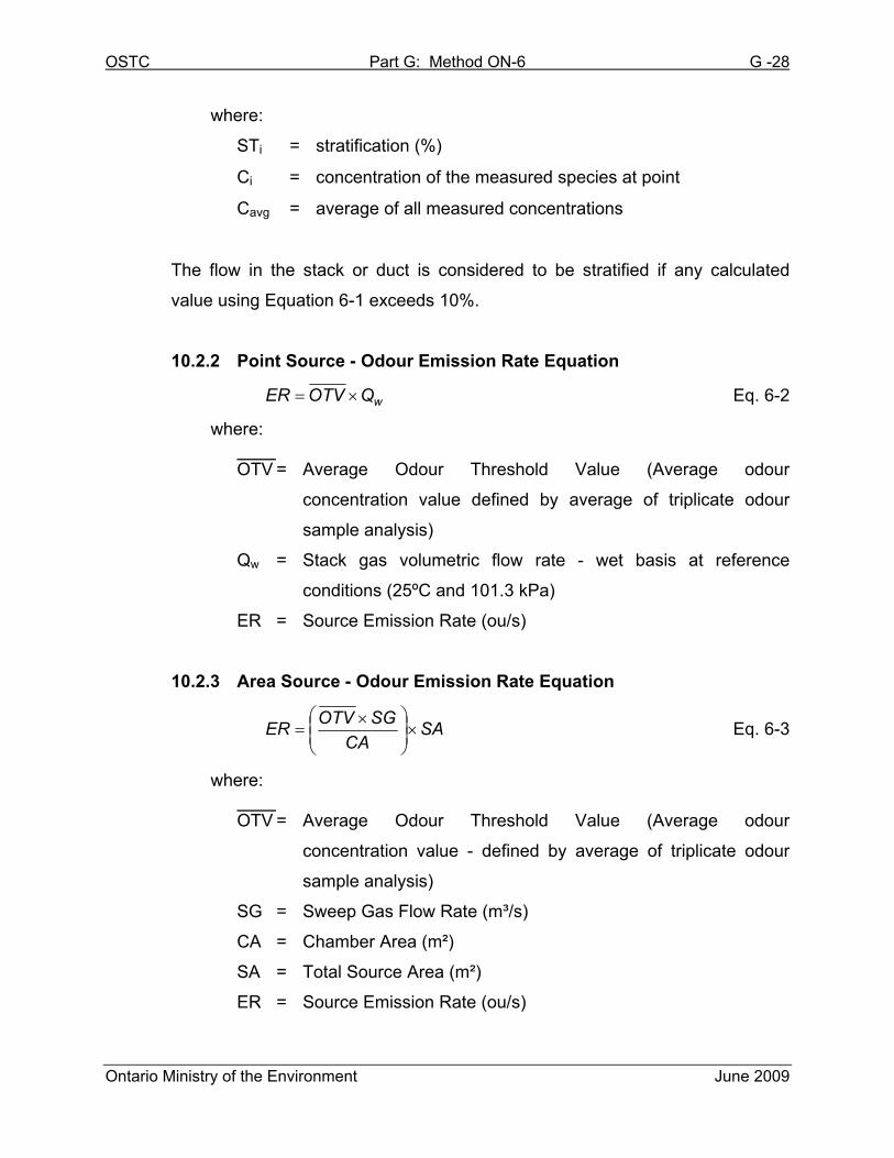
where:
STi = stratification (%)
Ci = concentration of the measured species at point
Cavg = average of all measured concentrations
The flow in the stack or duct is considered to be stratified if any calculated
value using Equation 6-1 exceeds 10%.
10.2.2 Point Source - Odour Emission Rate Equation
wQOTVER ×= Eq. 6-2
where:
OTV = Average Odour Threshold Value (Average odour
concentration value defined by average of triplicate odour
sample analysis)
Qw = Stack gas volumetric flow rate - wet basis at reference
conditions (25ºC and 101.3 kPa)
ER = Source Emission Rate (ou/s)
10.2.3 Area Source - Odour Emission Rate Equation
SACA
SGOTVER ×
×= Eq. 6-3
where:
OTV = Average Odour Threshold Value (Average odour
concentration value - defined by average of triplicate odour
sample analysis)
SG = Sweep Gas Flow Rate (m³/s)
CA = Chamber Area (m²)
SA = Total Source Area (m²)
ER = Source Emission Rate (ou/s)
OSTC Part G: Method ON-6 G -29
Ontario Ministry of the Environment June 2009
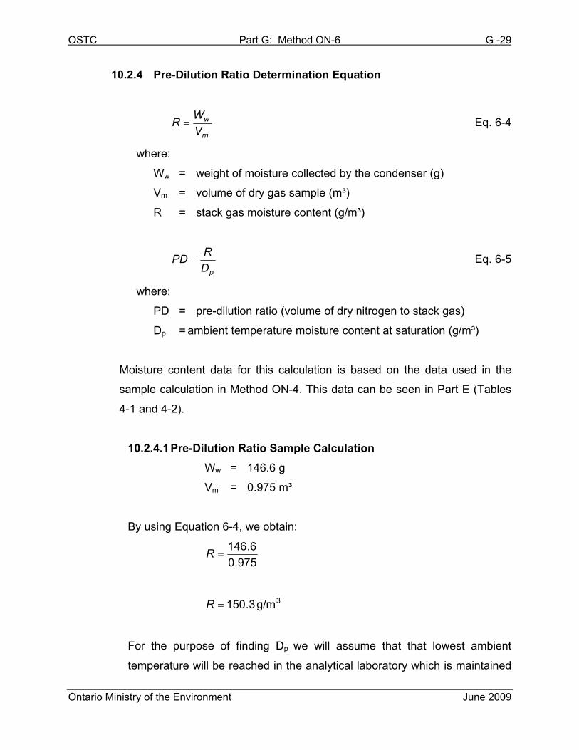
10.2.4 Pre-Dilution Ratio Determination Equation
m
w
V
WR = Eq. 6-4
where:
Ww = weight of moisture collected by the condenser (g)
Vm = volume of dry gas sample (m³)
R = stack gas moisture content (g/m³)
pD
RPD = Eq. 6-5
where:
PD = pre-dilution ratio (volume of dry nitrogen to stack gas)
Dp = ambient temperature moisture content at saturation (g/m³)
Moisture content data for this calculation is based on the data used in the
sample calculation in Method ON-4. This data can be seen in Part E (Tables
4-1 and 4-2).
10.2.4.1 Pre-Dilution Ratio Sample Calculation
Ww = 146.6 g
Vm = 0.975 m³
By using Equation 6-4, we obtain:
975.0
6.146=R
3g/m3.150=R
For the purpose of finding Dp we will assume that that lowest ambient
temperature will be reached in the analytical laboratory which is maintained
OSTC Part G: Method ON-6 G -30
Ontario Ministry of the Environment June 2009
at 21°C. Dp is then defined using Table 6-1.
Dp = 15.2 g/m³
2.15
3.150=PD
1:9.9=PD
Based on the calculation, the pre-dilution ratio used would be 10:1 (10 parts
dry nitrogen to 1 part stack gas) by volume.
10.3 APPENDIX 6C: Conditional Odour Sampling Methods
This chapter describes some of the successful non-traditional odour sampling
methods that have been applied in the past. These “Conditional Odour Sampling
Methods” are intended to provide some guidance in dealing with some non-
traditional odour sources. Please note that this chapter is for guidance purposes
only. It is necessary to contact the Source Assessment Specialist prior to
implementing these methods for compliance testing purposes.
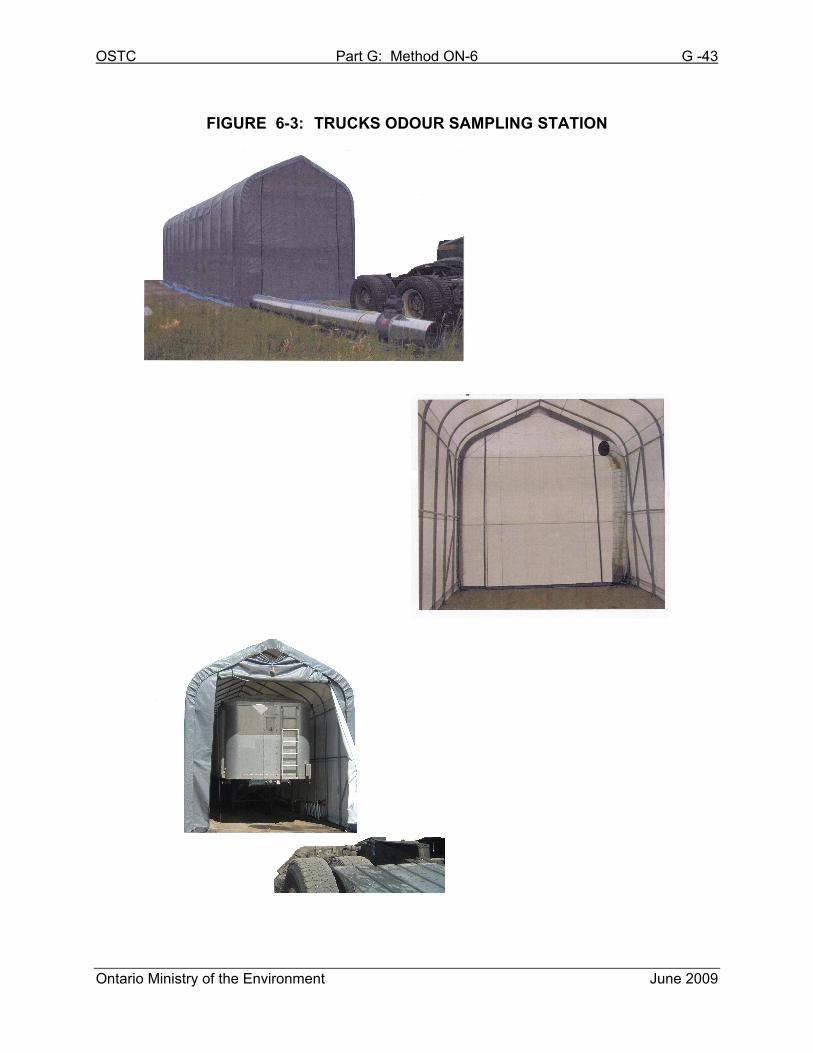
10.3.1 Sampling Truck Trailers and Bins
Sampling large area sources such as a truck trailer or a large bin presents
several challenges. The following is a brief description of a sampling method,
based on the wind tunnel principle, which has been successfully applied in the
past.
To facilitate the measurement of odours coming from truck trailers or bins, build
an enclosure to accommodate the largest truck trailer or bin of raw material.
Equip this enclosure with a passive air intake at one end and an exhaust
system used for the venting of odorous air at the other end. The air inlet should
be placed above the odour source and the outlet should be placed lower for the
purpose of inducing a cross draft. The exhaust will discharge odorous air from
OSTC Part G: Method ON-6 G -31
Ontario Ministry of the Environment June 2009
within the enclosure through a straight section of a duct which will provide an
ideal sampling location for both odour and volumetric flow rate. Refer to Figure
6-3 for a view of the enclosure.
Once the truck trailer or bin is placed within the enclosure and the door tightly
closed, the exhaust system is activated. Fresh air is allowed to enter the
opposite end of the enclosure through the passive air intake, which is an
opening equivalent in diameter to the exhaust duct diameter. The enclosure is
allowed to stabilize for a period sufficient to give at least two (2) air exchanges
prior to sample collection.
Once the enclosure is stabilized, odour samples are collected from the exhaust
duct with an evacuated lung sampling system (see Chapter 6). Care must be
taken to ensure that samples are not collected while there are ambient odours
around the enclosures, as this will bias the results.
At the beginning and at the end of each sampling day, a sample is collected
while the enclosure is empty to evaluate background levels.
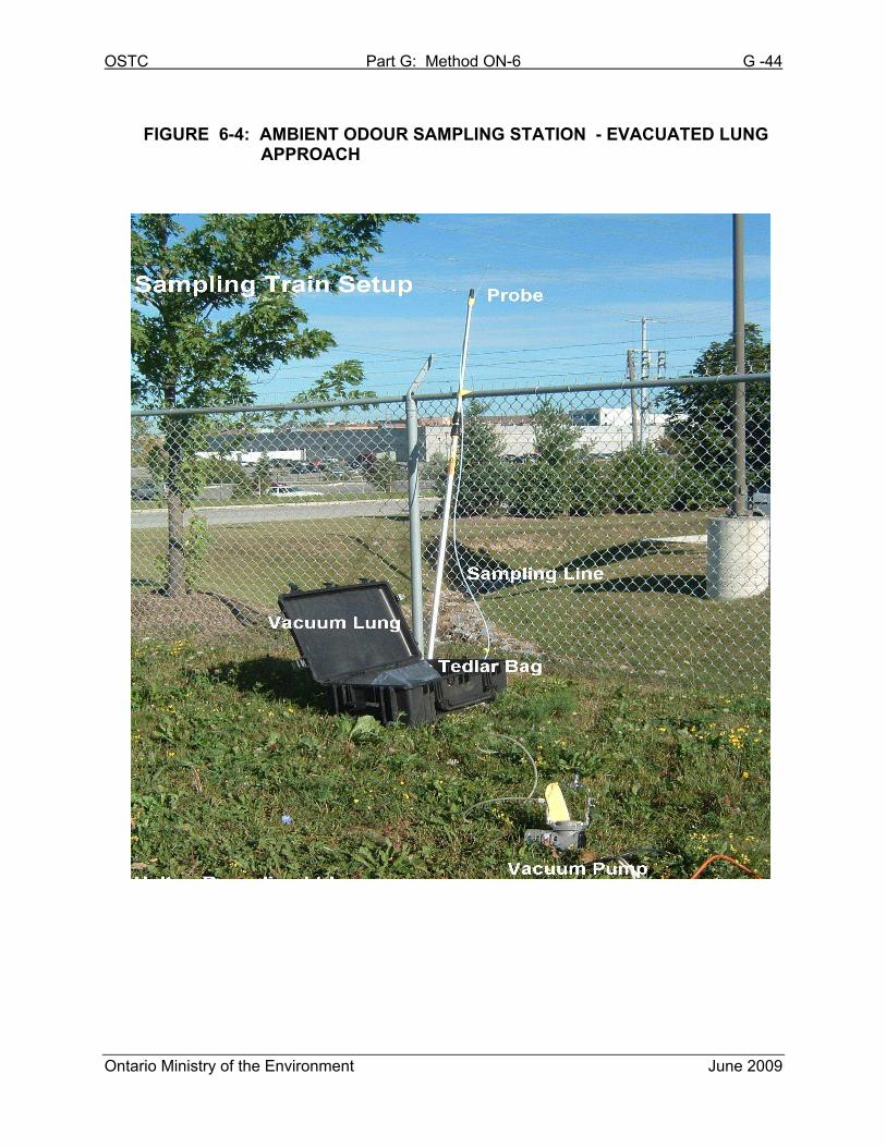
10.3.2 Ambient Odour Sampling via Evacuated Lung
There are several methods for measuring ambient odour. The most commonly
used method is a variation of the evacuated lung sampling method.
Note that ambient monitoring is not to be conducted on rainy days (or when rain
occurs within 24 hours of the scheduled sampling); as the rain will interfere with
the normal generation, release and collection of the odorous emissions (odour
scrubbing effect).
The sampling train consists of an evacuate lung sampling apparatus (see
Chapter 6.1) with a rigid probe. After selecting specific sampling locations
assemble the odour monitoring station (consisting of the evacuated lung
sampling system and the rigid sample probe) on the ground. Tedlar® bags
OSTC Part G: Method ON-6 G -32
Ontario Ministry of the Environment June 2009
(normally from 10 litres to 40 litres in capacity) are placed in the container and
connected to the sampling tubing. The sampling tubing tip (probe) is normally
held between 1.5 m and 2.0 m above ground, during the sampling, to reduce
the impact of ground turbulence and to set the sampling collection
approximately within a person’s breathing area.
The rigid vessel is sealed and the pump activated to evacuate the container
and to draw ambient air through the probe and into the Tedlar® bag. The
Tedlar® bag is partially filled (approximately 1/3 filled) with air sample, purged
and then refilled with the test sample.
Normally, samples are collected over a continuous period of 10 to 20 minutes.
For strong ambient odours, the sampling time is reduced to approximately
3 minutes to capture the most intense odours.
Following the sample collection, the Tedlar® bag samples are removed from
the evacuated lung, and capped with a Teflon fitting. The Tedlar® bags are
then placed inside a dark-coloured (garbage) bag to prevent photochemical
reactions of the odorous compounds and dispatched to the odour assessment
facility to be analyzed within 24 hours.
Weather conditions are normally monitored and recorded on a field data sheet
by the odour station coordinator.
A view of the sampling train setup is shown in Figure 6-4
10.3.3 Fugitive Odour Sampling
When assessing a facility’s aggregate odour impact it is necessary to address
the issue of fugitives. Fugitive sources of odour are elusive and difficult to
identify, such as leaky valves, flanges or passive ventilation apertures. These
sources may even release quantities of odorants intermittently making them
even more difficult to quantify.
OSTC Part G: Method ON-6 G -33
Ontario Ministry of the Environment June 2009
In certain instances fugitive sources may comprise the majority of a facility’s
aggregate odour emission rate; as such, it is essential that these sources are
quantified and included in a site-wide assessment of potential odour impacts.
There are several sampling methods which can be used to quantify fugitive
odours. Due to the unique nature of odour emitting facilities, it is often
necessary to adapt one or more of these methods to best suit each individual
situation. Having a qualified person develop a comprehensive strategy for
quantifying fugitive odour emissions is a key element to completing a
successful odour assessment. A Source Assessment Specialist should always
be contacted to discuss proposed sampling strategies prior to initiating a
program.
OSTC Part G: Method ON-6 G -34
Ontario Ministry of the Environment June 2009
11. REFERENCES
1. American Society for Testing and Materials, ASTM D1391-57, Standard Test
Method for Measurements of Odour on Atmospheres, (Dilution Method).
2. American Society for Testing and Materials, ANSI/ASTM E679-79. Standard
Practice for Determination of Odour and Taste Threshold by a Forced-choice
Ascending Concentration Series Method Limits.
3. Canadian Ortech Environmental Inc., Odour Evaluation Methodology.
Mississauga, Ontario. 2005.
4. Environment Canada, Report EPS 1/PG/7, Protocols and Performance
Specifications for Continuous Monitoring of Gaseous Emissions from Thermal
Power Generation. December 2005.
5. European Community for Standardization, Standard EN 13725 – Air Quality –
Determination of Odour Concentration by Dynamic Olfactometry. 2001.
6. Gnyp A. & al. (1974). Development procedures for determining industrial odour
thresholds. University of Windsor: Department of Chemical Engineering,
Windsor, Ontario.
7. Hopton, F., and Laughlin, R. (1974). Industrial odour measurement and control.
Ontario Research Foundation, Mississauga, Ontario.
8. Klopping, H.L. (1971). Olfactory theories and the odours of small molecules.
Journal of Agricultural and Food Chemistry, # 19.
OSTC Part G: Method ON-6 G -35
Ontario Ministry of the Environment June 2009
REFERENCES, continued
9. Ontario Ministry of Environment (1989). Source sampling for odours (Draft).
Toronto, Ontario.
10. Pinchin Environmental Ltd., Odour Evaluation Methodology. Mississauga,
Ontario. 2005.
11. Primer Environmental Services Inc., Source Sampling for Odours on an Open
Single-Bed Biofilter. Kitchener, Ontario. January 2001.
12. Schulman L et al., Development and Evaluation of the PRIME Plume Rise and
Building Downwash Model. Earth Tech Inc., Concord, Massachusetts.
(www.epa.gov/scram001/7thconf/iscprime/primpldn.pdf)
13. United States Environmental Protection Agency Code of Federal Regulations,
Title 40 Part 60, Method 25A.
14. U.S. Environmental Protection Agency (1986). Measurement of gaseous
emission rates from land surfaces using isolation flux chamber - user’s guide.
Las Vegas, Nevada.
OSTC Part G: Method ON-6 G -36
Ontario Ministry of the Environment June 2009
TABLE 6-1:
OSTC Part G: Method ON-6 G -37
Ontario Ministry of the Environment June 2009
TABLE 6-2: ODOUR SAMPLE DATA SHEET TEMPLATE SAMPLE #: SOURCE: SAMPLE DATE: TIME: START:
FINISH: PREDILUTION RATIO: EVALUATION DATE: ED50:
SAMPLE LINE DILUTION LINE
Hs FLOWRATE HD FLOWRATE
DILUTION RATIO
P STACK TEMP.
PROBE TEMP.
OSTC Part G: Method ON-6 G -38
Ontario Ministry of the Environment June 2009
TABLE 6-3: FLUX CHAMBER ODOUR SAMPLE DATA SHEET TEMPLATE
SOURCE: Pbar:
SAMPLE DATE: Ambient Temp:
SAMPLE LOCATION:
FLUX CHAMBER AREA:
EVALUATION DATE:
Sample #
Sweep Gas
Flow Rate
(L/min)
Sweep Gas
Start Time
Sampler
Temp
(°C)
Sample Flow
Rate
(L/min)
Sample
Start Time
Sample
Finish
Time
OSTC Part G: Method ON-6 G -39
Ontario Ministry of the Environment June 2009
FIGURE 6-1a: SKETCH OF AN ACCEPTABLE SAMPLING TRAIN FOR ODOUR SAMPLING (Dynamic Dilution Approach)
FIGURE 6-1b: SKETCH OF AN ACCEPTABLE SAMPLING TRAIN FOR ODOUR
SAMPLING (Evacuated Lung Approach)
Orifice
Orifice
Tedlar Bag
ProbeValve
Valve
Teflon Line
NitrogenFromStack
Valve
Sampling Lung
Tedlar Bag
Probe
Teflon Line
ToPump
FromStack
OSTC Part G: Method ON-6 G -40
Ontario Ministry of the Environment June 2009
FIGURE 6-1c: SKETCH OF AN ACCEPTABLE SAMPLING TRAIN FOR ODOUR
SAMPLING (Flux Chamber Approach)
Sample Flow
Flow meter Lung meter Pump
Flux Chamber Tedlar
Sample Bag
Teflon®
Sample Line
OSTC Part G: Method ON-6 G -41
Ontario Ministry of the Environment June 2009
FIGURE 6-1d: SKETCH OF AN ACCEPTABLE SAMPLING TRAIN FOR ODOUR
SAMPLING (Biofilter Bed Sample Train)
OSTC Part G: Method ON-6 G -42
Ontario Ministry of the Environment June 2009
FIGURE 6-2: FLUX CHAMBER ODOUR SAMPLING CONFIGURATION
OSTC Part G: Method ON-6 G -43
Ontario Ministry of the Environment June 2009
FIGURE 6-3: TRUCKS ODOUR SAMPLING STATION
OSTC Part G: Method ON-6 G -44
Ontario Ministry of the Environment June 2009
FIGURE 6-4: AMBIENT ODOUR SAMPLING STATION - EVACUATED LUNG
APPROACH