method for installation and use of embankment settlement ... · method for installation and use of...
TRANSCRIPT

California Test 112 STATE OF CALIFORNIA—BUSINESS, TRANSPORTATION AND HOUSING AGENCY August 2012
METHOD FOR INSTALLATION AND USE OF EMBANKMENT
SETTLEMENT DEVICES A. SCOPE The installation, maintenance, and data collection procedures for the various embankment settlement devices used to monitor subsurface settlement are described in this method. Analysis of the settlement data is included as a separate part of this method. Settlement devices are used to monitor the rate and magnitude of settlement occurring at a point within or beneath an embankment during and subsequent to construction. The data obtained from these devices are used to determine the allowable loading rate during embankment construction and the appropriate time for removal of surcharge and/or commencement of permanent structure construction. This method is divided into the following parts: 1. Fluid Level Settlement Devices 2. Pipe Riser Settlement Device 3. Settlement Data Analysis The fluid level vented standpipe unit may be used at most locations. A sealed standpipe unit must be installed at locations where groundwater may interfere with the operation of the unit or where excess pore water is expected from the use of dredged material or wet soil in embankment construction. Where it is possible, the tube length between standpipe and indicator unit should generally be limited to a maximum 300 linear ft. Installations over longer distances can be made but are not advisable under normal circumstances since it may result in inconsistent test data. Factors such as larger size tubes, change of platform location, or changes in elevation of the water line may have to be considered (see NOTE). NOTE: There may be job conditions with respect to terrain, long tube length between standpipe and indicator unit, or anticipated large settlements that require special installations. The pipe riser settlement device is used for monitoring fill settlement over soft foundation soils where the fluid level settlement devices are not feasible because of flat terrain, width of embankment construction, or other features which would make installation of a fluid level type of settlement platform undesirable. The pipe riser settlement device is a direct-reading unit which is exposed for the full duration of fill construction and surcharge removal. Because of the vulnerability of this unit to damage by the contractor’s operations, the pipe riser settlement device should be used only on those projects where the fluid level type of settlement device would be impractical. B. REFERENCE None.
DEPARTMENT OF TRANSPORTATION DIVISION OF ENGINEERING SERVICES Transportation Laboratory 5900 Folsom Boulevard Sacramento, California 95819-4612

California Test 112 August 2012
- 2 -
C. PROCEDURE
PART 1. FLUID LEVEL SETTLEMENT DEVICES SECTION 1. VENTED STANDPIPE UNIT
A. APPARATUS 1. Vented standpipe unit (see Figure 1). 2. Indicator unit (see Figure 2). 3. Polyethylene tubing, ⅜ in. inside diameter.
4. Hand tools – shovel, bar, posthole auger, hammer, adjustable wenches, etc.
5. Water container (approximately 1 gal capacity). B. INSTALLATION
1. Select a location for the standpipe unit on the ground after approximately one foot of fill has been placed above original ground and generally within the area where the maximum height of embankment will be placed (see Figure 4).
2. Select a point outside of the toe of the proposed embankment for the
indicator unit (see Figure 4). Select this location so that sufficient vertical distance will be available for lowering the indicator unit as the standpipe unit settles. A hand level may be used to estimate the desired elevations for the indicator unit.
3. Because of terrain, excessive anticipated settlement, or other causes, it
may be necessary to place the standpipe unit in the embankment at varying elevations above the original ground. In these cases, record the vertical distance between the base of the standpipe unit and original ground to allow proper consideration for embankment compression in the settlement analysis.
4. After embankment has been placed 3 to 5 ft above the desired elevation
for the standpipe unit, prepare a pit and trench in the embankment for the standpipe unit and tubing (see Figure 4). The bottom of the pit should normally be about one foot above original ground. The trench should be cut to the same depth at the pit and should have a slight downward slope to the indicator unit location. Make sure that the trench is clear of any future construction such as pile driving, ripping, ditching, etc.
5. Upon completion of the excavation, remove all rocks and large clods
from the trench. Prepare a smooth, level area in the pit using fine embankment material.
6. Assemble the standpipe unit as shown in Figure 1. Do not attach the
pipe cap. Firmly seat the standpipe unit on a prepared level area.
California Test 112 August 2012
- 3 -
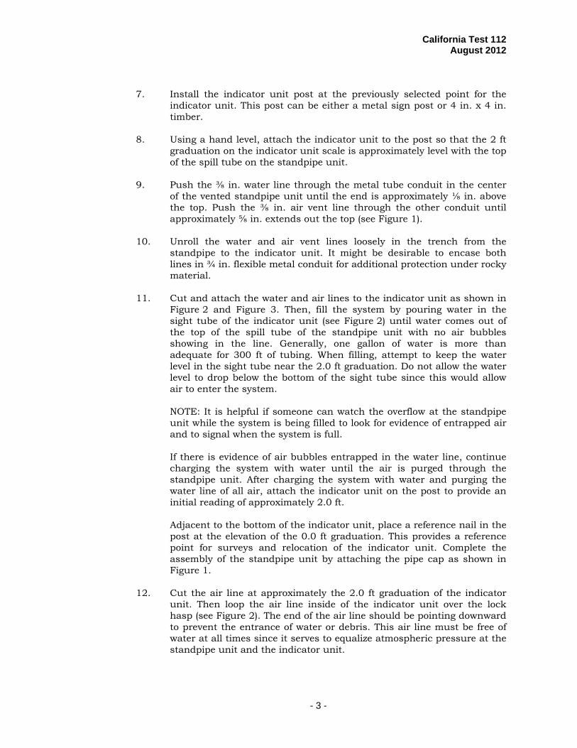
7. Install the indicator unit post at the previously selected point for the indicator unit. This post can be either a metal sign post or 4 in. x 4 in. timber.
8. Using a hand level, attach the indicator unit to the post so that the 2 ft
graduation on the indicator unit scale is approximately level with the top of the spill tube on the standpipe unit.
9. Push the ⅜ in. water line through the metal tube conduit in the center
of the vented standpipe unit until the end is approximately ⅛ in. above the top. Push the ⅜ in. air vent line through the other conduit until approximately ⅝ in. extends out the top (see Figure 1).
10. Unroll the water and air vent lines loosely in the trench from the
standpipe to the indicator unit. It might be desirable to encase both lines in ¾ in. flexible metal conduit for additional protection under rocky material.
11. Cut and attach the water and air lines to the indicator unit as shown in
Figure 2 and Figure 3. Then, fill the system by pouring water in the sight tube of the indicator unit (see Figure 2) until water comes out of the top of the spill tube of the standpipe unit with no air bubbles showing in the line. Generally, one gallon of water is more than adequate for 300 ft of tubing. When filling, attempt to keep the water level in the sight tube near the 2.0 ft graduation. Do not allow the water level to drop below the bottom of the sight tube since this would allow air to enter the system.
NOTE: It is helpful if someone can watch the overflow at the standpipe unit while the system is being filled to look for evidence of entrapped air and to signal when the system is full.
If there is evidence of air bubbles entrapped in the water line, continue charging the system with water until the air is purged through the standpipe unit. After charging the system with water and purging the water line of all air, attach the indicator unit on the post to provide an initial reading of approximately 2.0 ft.
Adjacent to the bottom of the indicator unit, place a reference nail in the post at the elevation of the 0.0 ft graduation. This provides a reference point for surveys and relocation of the indicator unit. Complete the assembly of the standpipe unit by attaching the pipe cap as shown in Figure 1.
12. Cut the air line at approximately the 2.0 ft graduation of the indicator
unit. Then loop the air line inside of the indicator unit over the lock hasp (see Figure 2). The end of the air line should be pointing downward to prevent the entrance of water or debris. This air line must be free of water at all times since it serves to equalize atmospheric pressure at the standpipe unit and the indicator unit.

California Test 112 August 2012
- 4 -
During cold weather when the air line is too stiff to be looped, cut the air line at the 1 ft graduation mark. Then insert the end of a one foot length of ¼ in. plastic tubing in the end of the air line and loop the smaller tubing inside the indicator unit.
13. Carefully backfill the trench and pit with material that is free from large
rocks or sharp objects and compact by hand for a depth of at least 12 in. Special care must be taken around the base of the standpipe unit to prevent separating the base plate from the plywood platform and to prevent breaking or distorting the plastic tubing.
14. After hand backfilling and compacting for a depth of 12 in. has been
completed, mechanical methods may be used to finish the backfilling operation until the trench is level with the existing fill height. In those cases when the standpipe unit extends above the existing fill height, attach a marker post to the unit and mound fill material around it until it is completely covered. In no case should compaction equipment be allowed directly over an installation until a minimum of 1 ft of compacted material has been placed over the standpipe unit.
SECTION 2. SEALED STANDPIPE UNIT A. APPARATUS 1. Sealed standpipe unit (see Figure 5). 2. Plastic drain tubing, ½ in. inside diameter. 3. Vented standpipe unit (as described in Part 1, Section 1(A)). B. INSTALLATION
Installation is similar to that for the vented standpipe unit with the following expectations:
1. Install the device as shown in Figure 6.
2. Follow the procedure in Part 1, Section 1(B)(1) through Section 1(B)(5).
3. Assemble the standpipe unit as shown in Figure 5. Do not attach the outer galvanized pipe. Firmly seat the standpipe unit on the prepared area in the pit.
4. Follow the procedure in Part 1, Section 1(B)(7) and Section 1(B)(8).
5. Attach the ⅜ in. water tube to the base plate as shown in Figure 5.
6. Unroll the water, air vent, and drain tubes loosely in the trench from the
standpipe to the indicator unit.
7. Follow the procedure in Part 1, Section 1(B)(10) and Section 1(B)(11).
8. Complete the assembly of the sealed standpipe unit by attaching the outer galvanized pipe, other fittings, air vent, and drain tubes.

California Test 112 August 2012
- 5 -
NOTE: It may be desirable in some cases to fill around the sealed units with sand so that the tubes will be supported at their attachment points.
9. Cut the drain tube near the base of the indicator unit post. Position the
drain tube so that water flows out freely and intrusion of soil or debris is prevented.
10. Follow the procedures in Part 1, Section 1 (B)(13) and Section 1(B)(14).
SECTION 3. POST-INSTALLATION PROCEDURES A. COLLECTION OF DATA
1. As soon as possible after the settlement device has been installed, determine the elevation of the reference to ± 0.01 ft by survey. This elevation should be checked periodically to correct settlement readings for settlement of indicator unit.
2. Settlement readings.
a. Note the height of water in the sight tube.
b. Pour sufficient water in the sight tube to raise the water level approximately 0.2 ft. c. Take a reading at 1 hr. The water level after adding the water should drop to the first reading or slightly above it.
d. If little or no change is observed in the water level, or if the water level is below the 0.05 ft graduation, refer to Part 2(C).
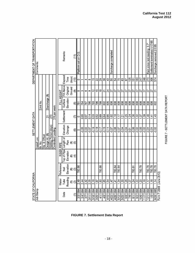
3. Record the data as indicated in Figure 7. The form is normally used to
record chronological data from a single settlement unit installed to monitor settlement. Instructions in filling out the form are as follows:
a. Settlement data report (see Figure 7).
Column 1 - Enter the date of the reading. Column 2 - Record the water level reading from the graduated scale on the indicator unit (after adding water as indicated above).
Column 3 - Record the latest elevation of either the 0.0 ft graduation on the indicator unit or the nail reference as determined by the survey. Columns 4 and 5 - These columns are not used. Column 6 - Enter the changes in water level elevation and reference elevation since the last reading. This is the sum of the differences between the current and immediately previous entries in Columns 2 and 3.

California Test 112 August 2012
- 6 -
Column 7 - Enter the total settlement as minus the elevation change since installation. This is obtained by changing the sign of the current data in Column 6 and adding this value to the previous entry in Column 7.
Column 8 - Enter the height of the fill at the surface as determined by survey (optional). Column 9 - Enter the height of fill above original ground in total feet. Column 10 - Enter the number of calendar days elapsed since the settlement device was installed. Column 11- Enter any information that would be helpful in the analysis of data as shown. If it is necessary to lower the indicator unit on the post, enter the date and the vertical distance lowered; be sure to include the corrected values in Columns 2, 3, and 6.
B. MAINTENANCE
1. Most important to the continued functioning of fluid level settlement devices is the use of as little water as necessary when recharging the system before reading. For this reason, use only enough water to raise the level in the sight tube approximately 0.2 ft. Continuous additions of greater quantities of water will probably cause flooding of the standpipe unit.
2. If the water level in the sight tube does not drop after adding water,
check the unit over a period of several days. Do not, however, add an excessive amount of water; just observe the system to see if the unit is slow to respond.
a. If the unit is not operating properly, remove the indicator box
from the post and raise it up about one foot. Disconnect the water line from the sight tube and attach the line upright on the post. Inspect the bottom of the sight tube and connector for debris. Remove any obstructions and reassemble the unit without losing water from the water line. After assembly, lower the indicator unit until water is observed in the sight tube, then recharge the system with clean water as necessary.
b. If the device is still not operating satisfactorily and the sealed
standpipe unit is being used, plug the top of the sight tube and attempt to force compressed air through the air line and out the drain line. Do not use greater air pressure than necessary to obtain a small flow through the lines. Do not allow the water in the sight tube to overflow. Keep the top of the sight tube sealed during this operation.
c. If all other attempts to correct the malfunction fail, disconnect
and drain the water line. Then apply compressed air at low pressure to the air line in an attempt to remove debris from the

California Test 112 August 2012
- 7 -
water line. If the sealed standpipe unit is used, plug the drain line during this operation. Occasionally, force air through the water line to clear the lines if no return is observed when pressurizing the air line. If successful in clearing obstructions from the water line in this manner, considerable care is required while recharging the system with water to not use too much water and to not introduce large voids in the system. For this reason, recharging the unit should be performed only by personnel experienced in this type of activity.
3. If the water level in the sight tube is below the 0.05 ft graduation or if
there is no water in the sight tube, look for leaks around the connection between the sight tube and the water line. If no leak is seen, measure the vertical difference between the 0.0 ft graduation on the indicator unit and the reference point. Remove the unit from the post and lower it approximately 1.5 ft or until water is observed in the sight tube. If possible, and without adding water, adjust the height of the indicator unit on the post so that the water level in the sight tube is approximately at the 2.0 ft graduation. Add a small quantity of water and check the water level before attaching the indicator unit to the post. After adjusting the height of the indicator unit, again measure the vertical distance between the 0.0 ft graduation on the indicator unit and the reference point and record the correction on the settlement data form (Figure 7, Column 3).
4. Be sure to replace the cover on the indicator unit after each reading to
prevent excessive loss by evaporation and contamination by debris. 5. Occasionally, it may be necessary to protect the air and water lines from
rodents or pests. If such a problem exists, protect these lines in flexible conduit extending from the bottom of the indicator unit to below the ground surface. Although this should be done during installation, the conduit can be added later if extreme care is taken not to lose water continuity as described above.
PART 2. PIPE RISER SETTLEMENT DEVICE A. APPARATUS
1. Pipe riser settlement device (see Figure 8).
2. Hand tools - shovel, bar, hammer, pipe wrenches, etc.
B. INSTALLATION
1. It will usually be necessary to determine the location for installing the settlement device by survey. If settlement readings are to be continued after completion of the fill and removal of surcharge, it is imperative that the unit be located directly beneath the median of divided travel lanes or the shoulder of other roadways.
2. After approximately 3 ft of embankment material has been placed,
excavate a pit to a depth of approximately 1 ft above original ground at

California Test 112 August 2012
- 8 -
the previously determined location for the settlement device. Prepare a firm, level area free of large rocks or clods for the settlement device at the bottom of the pit.
3. Assemble the settlement device as shown in Figure 8. Attach a ¾ in.
pipe floor flange to the center of the wood platform with bolts or lag screws. Then screw a 6 ft length of ¾ in. pipe into the floor flange. Place a pipe coupling on the top of the ¾ in. pipe and tighten all joints in the assembly using a pipe wrench.
4. Measure and record the distance from the top of the pipe coupling to the
top of the wood platform. Then slip the 1½ in. x 5 ft protective sleeve, which may be either rigid polyvinyl chloride (PVC) or iron pipe, over the control pipe until it is about 2 in. above the floor flange. Place a duct seal or other seal to hold the protective sleeve in place (see Figure 8). Do not attach the protective sleeve to the wood platform or the control pipe. This protective sleeve is used to absorb the friction between the fill material and the settlement unit and, therefore, must be free to move independently from the wood platform and control pipe.
5. Firmly seat the settlement device on the prepared area in the bottom of
the pit. Then fill and compact by hand using fine embankment material free of large rocks and clods around the settlement device to a depth of one foot.
6. Using a spirit level, check to make sure the control pipe is reasonably
plumb, then carefully fill the pit with embankment material and compact in place.
7. Attach a post to the top of the protective sleeve to alert construction
equipment operators of the obstruction.
NOTE: It has been found that a 6 ft long, 2 in. x 4 in. post painted with alternate 1 ft wide stripes of red and white is satisfactory for this use. It is recommended that flagging be attached to the top of this post. The post should be attached so that it can be easily removed and reattached as additional pipe is added during embankment construction.
C. COLLECTION OF DATA
1. As soon as possible after the settlement device has been installed,
determine the elevation of the top of the ¾ in. pipe coupling attached to the control pipe. Normally, the elevations required will be obtained by a survey party.
2. During embankment construction, the elevation of the top of the control
pipe should be determined by survey approximately twice weekly. After embankment construction is completed, the elevation should be determined frequently enough to indicate significant changes in the rate of settlement. Normally, the time between surveys will be weekly immediately subsequent to completion of the embankment, and the interval between surveys will increase with time.

California Test 112 August 2012
- 9 -
3. During fill placement, it will be necessary to extend the lengths of the control pipe and protective sleeve. When extending the control pipe, use the following procedure:
a. Determine the elevation to the top of the existing control pipe
coupling. b. Remove the protective post, attach a coupling to the length of
control pipe to be added, and tighten the joint with pipe wrenches.
c. Insert the added length in the coupling on top of the existing
control pipe and tighten the joint by using one pipe wrench on the existing coupling and one pipe wrench on the added length of control pipe. While tightening the joint, do not allow the coupling between the control pipe and the added length to turn. Turn only the added length of control pipe.
d. Measure the added length of control pipe, including the coupling.
If possible, check this distance by determining the elevation of the control pipe.
e. Record the length of additional control pipe added under Column
5 on the form shown in Figure 9. Be sure to add this length to the previous value shown in Column 4.
f. Add and secure a 5 ft length of protective sleeve to the existing
sleeve and secure to the top of the post.
4. Enter all data on the form provided (see Figure 11) using the example shown in Figure 9 as follows:
Column 1 - Record the reading date. Column 2 - This column is not used. Column 3 - This column is not used. Column 4 - Record the elevation to top of control pipe as determined by survey. Column 5 - Record the length of the control pipe. Column 6 - Record the height of the riser above the original ground (Column 4 minus Column 5). Column 7 -Record the total settlement in feet. This figure is obtained by subtracting the figure in Column 6 for the day being read from the figure at the top of Column 6 (elevation at the time of installation). Column 8 - Record the elevation of the surface of the fill as determined by survey (that is optional).

California Test 112 August 2012
- 10 -
Column 9 - Record the height of the fill above original ground in total feet. Column 10 - Record the number of calendar days elapsed since the settlement device was installed. Column 11 - Record any information that would be helpful in the analysis of data. Be sure to indicate in this column the date and length added to the control pipe.
PART 3. SETTLEMENT DATA ANALYSIS The procedure for plotting and analyzing settlement data obtained from all types of settlement devices is described in this method. Comprehensive settlement analyses are complex and require extensive knowledge of soil mechanics and soil structure of the area under study. Considerable information, however, can be obtained by the simplified method described in this part.
1. Plot the data on a semi-logarithmic chart as shown in Figure 10. Note that the scale for days is on the logarithmic abscissa of the chart and both settlement and fill height are scaled arithmetically on the ordinate.
2. Note that during construction, the rate of settlement increases in approximate
proportion to the fill load applied. This is generally true in all cases where the rate of loading embankment is nearly constant. If embankment construction is suspended for an appreciable length of time, the negative slope indicating rate of settlement should become more positive or flatter until embankment construction resumes. In no case, however, should the rate of settlement curve assume a positive slope.
a. A sudden increase in the rate of settlement during construction is
an indication of impending failure and would dictate that fill loading be stopped immediately.
b. If the rate of settlement remains excessive after suspending fill
operations, additional corrective measures must be taken to reduce the rate of settlement.
NOTE: This may include removing a portion of the embankment or constructing berms or struts. Such measures usually require a comprehensive analysis and, for that reason, the problem must be brought to the attention of the project engineer without delay.
3. After embankment construction has been completed, the rate of settlement will decrease with time, especially for soft foundation soils. However, a marked decrease in the rate of settlement may be noticed until an appreciable amount of time has elapsed since completion of the embankment.
a. Any significant increase in the rate of settlement after completion of the
embankment is sufficient cause for immediate corrective action as described above.

California Test 112 August 2012
- 11 -
b. When the plotted data indicate that the slope of the rate of settlement curve is essentially horizontal, the embankment surcharge may be removed and/or permanent structure construction may be started. For example, from data shown in Figure 10, a practical minimal rate of settlement was obtained at about 360 days; at this time the embankment surcharge was removed as shown.
4. Data should be collected throughout the life of the contract. Longer data
collection periods are necessary if significant rates of settlement are measured.
a. The time interval between readings may be increased as the indicated rate of movement decreases.
b. Collection of data may be required for several years on selected projects.
Long-term settlement data are frequently useful in the design of embankments where similar conditions are encountered.
D. HEALTH AND SAFETY It is the responsibility of the user of this test method to establish appropriate health and safety practices and determine the applicability of regulatory limitations prior to use. Prior to handling, testing or disposing of any materials, testers must be knowledgeable about safe laboratory practices, hazards and exposure, chemical procurement and storage, and personal protective apparel and equipment. Caltrans Laboratory Safety Manual is available at:
http://www.dot.ca.gov/hq/esc/ctms/pdf/lab_safety_manual.pdf
Users of this method do so at their own risk.
End of Text
(California Test 112 contains 22 pages)

California Test 112 August 2012
- 12 -
FIGURE 1. Vented Standpipe Unit

California Test 112 August 2012
- 13 -
FIGURE 2. Indicator Unit

California Test 112 August 2012
- 14 -
FIGURE 3. Detail of Indicator Unit

California Test 112 August 2012
- 15 -
Figure 4. Settlement Indicator Device (Vented Type)

California Test 112 August 2012
- 16 -
FIGURE 5. Sealed Standpipe

California Test 112 August 2012
- 17 -
FIGURE 6. Settlement Indicator Device (Sealed Fluid Level Type)
California Test 112 August 2012
- 18 -
FIGURE 7. Settlement Data Report

California Test 112 August 2012
- 19 -
FIGURE 8. Pipe Riser Settlement Device

California Test 112 August 2012
- 20 -
FIGURE 9. Settlement Data Report

California Test 112 August 2012
- 21 -
FIGURE 10. Settlement Data Analysis

California Test 112 August 2012
- 22 -
FIGURE 11. Settlement Data Report (blank)