method 555 determination of chlorinated … · 555-1 method 555 determination of chlorinated acids...
TRANSCRIPT
555-1
METHOD 555
DETERMINATION OF CHLORINATED ACIDS IN WATER BY HIGH PERFORMANCELIQUID CHROMATOGRAPHY WITH A PHOTODIODE ARRAY
ULTRAVIOLET DETECTOR
Revision 1.0
August 1992
James W. Eichelberger
Winslow J. Bashe (Technology Applications, Inc.)
ENVIRONMENTAL MONITORING SYSTEMS LABORATORYOFFICE OF RESEARCH AND DEVELOPMENT
U. S. ENVIRONMENTAL PROTECTION AGENCYCINCINNATI, OHIO 45268

555-2
METHOD 555
DETERMINATION OF CHLORINATED ACIDS IN WATER BY HIGH PERFORMANCELIQUID CHROMATOGRAPHY WITH A PHOTODIODE ARRAY
ULTRAVIOLET DETECTOR
1.0 SCOPE AND APPLICATION
1.1 This is a high performance liquid chromatographic (HPLC) method for thedetermination of certain chlorinated acids in ground water and finisheddrinking water. The following compounds can be determined by this method:
Analyte Registry NumberChemical Abstract Services
Acifluorfen 50594-66-6Bentazon 25057-89-0Chloramben 133-90-4a
2,4-D 94-75-72,4-DB 94-82-6Dicamba 1918-00-93,5-Dichlorobenzoic acid 51-36-5Dichlorprop 120-36-5Dinoseb 88-85-75-Hydroxydicamba 7600-50-2a
MCPAMCPP4-Nitrophenol 100-02-7a
Pentachlorophenol (PCP) 87-86-5b
Picloram 1918-02-1a
2,4,5-T 93-76-52,4,5-TP 93-72-1
Analytes measurable from 20 mL sample volume only.a
Use a 100 mL sample for pentachlorophenol in order to attain a MDL ofb
0.3 µg/L. The MLC for this compound is 1.0 µg/L.
1.2 This method is applicable to the determination of salts and esters of analyteacids. The form of each analyte is not distinguished by this method. Resultsare calculated and reported for each listed analyte as the total free acid.
1.3 This method has been validated in a single laboratory and method detectionlimits (MDLs) have been determined from a 20 mL sample for the analytes1
above. Observed MDLs may vary among ground waters, depending on thenature of interferences in the sample matrix and the specific instrumentationused.

555-3
1.4 This method is restricted to use by or under the supervision of analystsexperienced in the use of HPLC and in the interpretation of chromatograms. Each analyst must demonstrate the ability to generate acceptable results withthis method using the procedure described in Section 9.3.
1.5 Analytes that are not separated chromatographically cannot be individuallyidentified and measured in the same calibration mixture or water sampleunless an alternative technique for identification and quantitation exists(Section 11.3).
1.6 When this method is used to analyze unfamiliar samples, analyteidentifications must be confirmed by at least one additional qualitativetechnique.
2.0 SUMMARY OF METHOD
2.1 A measured sample volume of approximately 100 mL is adjusted to pH 12with 6 N sodium hydroxide, shaken, and allowed to set for 1 hr to hydrolyzechlorinated esters. The sample is acidified with H PO , filtered, and the3 4
chlorinated acids are extracted from a 20 mL aliquot. The 20 mL aliquot ispumped through an HPLC cartridge (containing C -silica), trapping the18
chlorinated acids. The concentrator cartridge is valved in-line with the C18
analytical column following extraction. The analytes are separated andmeasured by photodiode array - ultraviolet detection (PDA-UV).
NOTE: A liquid-solid extraction disk is perfectly acceptable for use in the in-line extraction of the analytes providing all quality control (QC) criteria inSection 9.0 are met or exceeded.
2.2 The method measures the analytes from 20 mL volumes. Volumes of up to100 mL may be analyzed by this procedure for certain analytes. The analyteswhich may not be determined in a larger volume are indicated in Section 1.1.
3.0 DEFINITIONS
3.1 Laboratory Duplicates (LD1 AND LD2) -- Two aliquots of the same sampletaken in the laboratory and analyzed separately with identical procedures. Analyses of LD1 and LD2 indicate the precision associated with laboratoryprocedures, but not with sample collection, preservation, or storageprocedures.
3.2 Field Duplicates (FD1 AND FD2) -- Two separate samples collected at thesame time and place under identical circumstances and treated exactly thesame throughout field and laboratory procedures. Analyses of FD1 and FD2give a measure of the precision associated with sample collection, preservationand storage, as well as with laboratory procedures.

555-4
3.3 Laboratory Reagent Blank (LRB) -- An aliquot of reagent water or other blankmatrix that is treated exactly as a sample including exposure to all glassware,equipment, solvents, and reagents that are used with other samples. The LRBis used to determine if method analytes or other interferences are present inthe laboratory environment, the reagents, or the apparatus.
3.4 Field Reagent Blank (FRB) -- An aliquot of reagent water or other blank matrixthat is placed in a sample container in the labora-tory and treated as a samplein all respects, including shipment to the sampling site, exposure to samplingsite conditions, storage, preservation, and all analytical procedures. Thepurpose of the FRB is to determine if method analytes or other interferencesare present in the field environment.
3.5 Laboratory Fortified Blank (LFB) -- An aliquot of reagent water or other blankmatrix to which known quantities of the method analytes are added in thelaboratory. The LFB is analyzed exactly like a sample, and its purpose is todetermine whether the methodology is in control, and whether the laboratoryis capable of making accurate and precise measurements.
3.6 Laboratory Fortified Sample Matrix (LFM) -- An aliquot of an environmentalsample to which know quantities of the method analytes are added in thelaboratory. The LFM is analyzed exactly like a sample, and its purpose is todetermine whether the sample matrix contributes bias to the analytical results. The background concentrations of the analytes in the sample matrix must bedetermined in a separate aliquot and the measured values in the LFMcorrected for background concentrations.
3.7 Stock Standard Solution (SSS) -- A concentrated solution containing one ormore method analytes prepared in the laboratory using assayed referencematerials or purchased from a reputable commercial supplier.
3.8 Primary Dilution Standard Solution (PDS) -- A solution of several analytesprepared in the laboratory from stock standard solutions and diluted asneeded to prepare calibration solutions and other needed analyte solutions.
3.9 Calibration Standard (CAL) -- A solution prepared from the primary dilutionstandard solution or stock standard solutions and the internal standards andsurrogate analytes. The CAL solutions are used to calibrate the instrumentresponse with respect to analyte concentration.
3.10 Quality Control Sample (QCS) -- A solution of method analytes of knownconcentrations which is used to fortify an aliquot of LRB or sample matrix. The QCS is obtained from a source external to the laboratory and differentfrom the source of calibration standards, It is used to check laboratoryperformance with externally prepared test materials.

555-5
3.11 Method Detection Limit (MDL) -- The minimum concentration of an analytethat can be identified, measured and reported with 99% confidence that theanalyte concentration is greater than zero.
3.12 External Standard (ES) -- A pure analyte(s) that is measured in an experimentseparate from the experiment used to measure the analyte(s) in the sample. The signal observed for a known quantity of the external standard(s) is used tocalibrate the instrument response for the corresponding analytes(s). Theinstrument response is used to calculate the concentrations of the analyte(s) inthe sample.
4.0 INTERFERENCES
4.1 Method interferences may be caused by contaminants in solvents, reagents,glassware, and other sample processing apparatus that lead to discrete artifactsor elevated baselines in liquid chromatograms. All reagents and apparatusmust be routinely demonstrated to be free from interferences under theconditions of the analysis by analyzing laboratory reagent blanks as describedin Section 9.2.
4.1.1 Glassware must be scrupulously cleaned . Clean all glassware as soon3
as possible after use by thoroughly rinsing with the last solvent used init. Follow by washing with hot water and detergent and thoroughrinsing with dilute acid, tap and reagent water. Drain dry, and heat inan oven or muffle furnace at 400°C for one hour. Do not heatvolumetric ware. Thermally stable materials such as PCBs might not beeliminated by this treatment. Thorough rinsing with acetone may besubstituted for the heating. After drying and cooling, seal and storeglassware in a clean environment to prevent any accumulation of dustor other contaminants. Store inverted or capped with aluminum foil.
4.1.2 The use of high purity reagents and solvents helps to minimizeinterference problems. Purification of solvents by distillation in all-glass systems may be required.
WARNING: When a solvent is purified, stabilizers added by themanufacturer are removed, thus potentially making the solventhazardous. Removal of preservatives by distillation may also reducethe shelf-life of the solvent.
4.2 The acid forms of the analytes are strong organic acids which react readilywith alkaline substances and can be lost during sample preparation. Glassware must be acid-rinsed with 1 N hydrochloric acid prior to use toavoid analyte losses due to adsorption.
4.3 Matrix interferences may be caused by contaminants that are coextracted fromthe sample. Also, note that all method analytes are not resolved from eachother on a single column, i.e., one analyte of interest may interfere withanother analyte of interest. The extent of matrix interferences will vary

555-6
considerably from source to source, depending upon the water sampled. Theprocedures in Section 11.0 can be used to overcome many of theseinterferences. Tentative identifications should always be confirmed(Section 11.3).
5.0 SAFETY
5.1 The toxicity or carcinogenicity of each reagent used in this method has notbeen precisely defined; however, each chemical compound must be treated asa potential health hazard. Accordingly, exposure to these chemicals must bereduced to the lowest possible level. The laboratory is responsible formaintaining a current awareness file of OSHA regulations regarding the safehandling of the chemicals specified in this method. A reference file of materialsafety data sheets should also be made available to all personnel involved inthe chemical analysis.
WARNING: When a solvent is purified, stabilizers added by the manufacturerare removed, thus potentially making the solvent hazardous. Therefore,storage of large volumes of purified solvents may be hazardous. Therefore,only small volumes of solvents should be purified just before use.
6.0 EQUIPMENT AND SUPPLIES
6.1 Sample Bottle -- Borosilicate, 125 mL volume, graduated, fitted with Teflon-lined screw cap. Protect samples from light. The container must be washedand dried as described in Section 4.1.1 before use to minimize contamination. Cap liners may be cut to fit from Teflon sheets and extracted with methanolovernight prior to use.
6.2 Glassware
6.2.1 Volumetric flask, Class A -- 100 mL, with ground glass stoppers.
6.2.2 Graduated cylinder -- 100 mL.
6.2.3 Disposable pipets, transfer -- Borosilicate glass.
6.2.4 Glass syringe -- 50 mL, with Luer-Lok fitting.
6.2.5 Volumetric pipette, Class A -- 20 mL.
6.3 Balance -- Analytical, capable of accurately weighing to the nearest 0.0001 g.
6.4 Liquid Chromatograph -- Analytical system complete with gradientprogrammable HPLC suitable for use with analytical HPLC columns and allrequired accessories including an injector, analytical column, semi-prep guardcolumn, and photodiode array UV detector. A data system is necessary formeasuring the peak areas and for assessing the confirmation of the peakidentification. A personal computer (PC) of at least the AT-class is generally

555-7
needed to control and collect data from the photodiode array UV detector. Table 1 lists the retention times observed for the method analytes using thecolumn and analytical conditions described below. Figure 1 is a schematicdrawing of the analytical system including the sample concentrator column(semi-prep guard column).
6.4.1 Primary column -- 250 mm x 4.6 mm I.D. ODS-AQ, 5 µm spherical(YMC Ltd.). Any column may be used if equivalent or betterperformance (better peak shape, better analyte efficiency, or morecomplete separation of analytes) can be demonstrated. Mobile phaseflow rate is established at 1.0 mL/min (linear velocity of 6.0 cm/min). Two mobile phase components are used: A -- 0.025 M H PO ; B --3 4
Acetonitrile. A gradient solvent program is used to separate theanalytes: 90:10 A:B to 10:90 A:B in 30 minutes, linear ramp/hold at10:90 for 10 minutes. Reverse the gradient and establish initialconditions: 10:90 A:B to 90:10 A:B in 10 minutes, linear ramp. Allowcolumn backpressure to restablize for 5-10 minutes before beginning thenext analysis. Total restabilization time will be determined by eachanalyst.
6.4.2 Confirmation column -- 300 mm x 3.9 mm I.D. Nova-Pak C , 4 µm18
spherical (Waters Chromatography Division, Millipore). Any columnmay be used if equivalent or better performance (better peak shape,better analyte efficiency, or more complete separation of analytes) canbe demonstrated. Mobile phase and conditions same as primarycolumn.
6.4.3 Sample concentrator column -- 30 mm x 10 mm I.D. ODS-AQ, 5 µmspherical (YMC Ltd). An alternative concentrator column may be usedif all QC criteria in Section 9.0 can be equalled or improved. Also, aliquid-solid extraction disk may be used if all QC criteria in Section 9.0can be equalled or improved.
6.4.4 Six-port switching valve -- Rheodyne Model 7000 (Rheodyne Corp).
6.4.5 Sample delivery pump -- A piston-driven pump capable of deliveringaqueous sample at a flow rate of 5.0 mL/min. An analytical HPLCpump may serve as the sample delivery pump. A Waters Model 6000Awas used to generate the data presented in this method.
6.4.6 Detector -- Photodiode array. Ultraviolet (PDA-UV), LKB-BrommaModel 2140 Rapid Spectral Detector or equivalent. Detectorparameters: Scan Range - 210-310 nm at 1 scan/sec, detectorintegration - one second.
6.4.7 Data handling system -- DOS-based Personal Computer, AT-classmachine or machine of greater capability with 640 K RAM or more, an80 Mb hard disk or larger, VGA monitor or equivalent.

555-8
7.0 REAGENTS AND STANDARDS
7.1 Acetonitrile -- HPLC Grade or equivalent.
7.2 Sodium Sulfite -- Granular, anhydrous, ACS grade.
7.3 Sodium Hydroxide (NaOH) -- Pellets, ACS grade.
7.3.1 NaOH, 6 N -- Dissolve 216 g NaOH in 900 mL reagent water.
7.4 Phosphoric Acid -- 85% AR, ACS grade.
7.4.1 0.025 M -- Mix 2.0 mL of H PO in 998 mL of reagent water.3 4
7.5 Stock Standard Solutions (1.00 µg/µL) -- Stock standard solutions may bepurchased as certified solutions or prepared from pure standard materialsusing the following procedure:
7.5.1 Prepare stock standard solutions by accurately weighing approximately0.0100 g of pure material. Dissolve the material in acetonitrile anddilute to volume in a 10 mL volumetric flask. Larger volumes may beused at the convenience of the analyst. If compound purity is certifiedat 96% or greater, the weight may be used without correction tocalculate the concentration of the stock standard. Commerciallyprepared stock standards may be used at any concentration if they arecertified by the manufacturer or by an independent source.
7.5.2 Transfer the stock standard solutions into Teflon-lined sealed screw capamber vials. Store at room temperature and protect from light.
7.5.3 Stock standard solutions should be replaced after two months or soonerif comparison with laboratory fortified blanks, or QC samples indicate aproblem.
7.6 Hydrochloric Acid -- ACS grade.
7.6.1 HCl, 1 N -- Dilute 50 mL in 600 mL of reagent water.
7.7 Filters -- 0.45 µm, Nylon, 25 mm i.d. (Gelman Sciences).
8.0 SAMPLE COLLECTION, PRESERVATION, AND STORAGE
8.1 Grab samples must be collected in glass containers. Conventional samplingpractices should be followed; however, the bottle must not be prerinsed with2
sample before collection.

555-9
8.2 Sample Preservation and Storage
8.2.1 Add hydrochloric acid (1:1) to the sample to produce a pH of 2. ThepH may be measured in the field using pH indicator strips.
8.2.2 Residual chlorine should be reduced at the sampling site by theaddition of a reducing agent. Add 4-5 mg of sodium sulfite (this maybe added as a solid with shaking until dissolved) to each 100 mL ofwater.
8.2.3 The samples must be iced or refrigerated at 4°C away from light fromthe time of collection until extraction. The samples must be analyzedwithin 14 days of collection. However, analyte stability may be affectedby the matrix. Therefore, the analyst should verify that thepreservation technique is applicable to the samples under study. If the14-day holding time is exceeded, the data should be flagged so that thedata user is aware of possible analyte degradation.
8.2.4 Field reagent blanks (FRB) -- Processing a FRB is recommended alongwith each set, which is composed of the samples collected from thesame general sample site at approximately the same time. At thelaboratory, fill a sample container with reagent water, seal, and ship tothe sampling site along with the empty sample containers. Duringsample collection, open the FRB and add H6 (Section 8.2.1) and sodiumsulfite (Section 8.2.2) Return the FRB to the laboratory with filledsample bottles.
9.0 QUALITY CONTROL
9.1 Minimum QC requirements are initial demonstration of laboratory capability,analysis of laboratory reagent blanks, laboratory fortified samples, laboratoryfortified blanks, and QC samples.
9.2 Laboratory Reagent Blanks (LRB) -- Before processing any samples, the analystmust demonstrate that all glassware and reagent interferences are undercontrol. Each time a set of samples is extracted or reagents are changed, a LRBmust be analyzed. If within the retention time window of any analyte the LRBproduces a peak that would prevent the determination of that analyte,determine the source of contamination and eliminate the interference beforeprocessing samples.
9.3 Initial Demonstration of Capability
9.3.1 Select a representative fortified concentration for each analyte. Preparea sample concentrate (in acetonitrile) containing each analyte at1000 times the selected concentration. With a syringe, add 100 µL ofthe concentrate to each of at least four 100 mL aliquots of reagentwater, and analyze each aliquot according to procedures beginning inSection 11.0.

555-10
9.3.2 Calculate the recoveries, the relative standard deviation, and theMDLs . For each analyte the recovery value for all four of these5
samples must fall in the range of R ±30%, using the value for R forreagent water in Table 2. As the calibration procedure employs afortified reagent water blank for the determination of the calibrationcurves or factors, the recovery values for the analytes should, bydefinition, be within this range. If the mean recovery of any analytefails this demonstration, repeat the measurement of that analyte todemonstrate acceptable performance.
9.3.3 The initial demonstration of capability is used primarily to preclude alaboratory from analyzing unknown samples using a new, unfamiliarmethod prior to obtaining some experience with it. As laboratorypersonnel gain experience with this method the quality of data shouldimprove beyond what is required here.
9.4 The analyst is permitted to modify LC columns, LC conditions, and detectors. Each time such method modifications are made, the analyst must repeat theprocedures in Section 9.3.
NOTE: The LC column and guard cartridge used to generate the data in thismethod were found to be unique C -silica columns. Before substituting other18
C columns, a careful review of the literature is recommended.18
9.5 Assessing Laboratory Performance -- Laboratory Fortified Blank (LFB)
9.5.1 The laboratory must analyze at least one LFB sample with every20 samples or one per sample set (all samples analyzed within a24-hour period) whichever is greater. The concentration of each analytein the LFB should be 10 times the MDL or the MCL, whichever is less. Calculate accuracy as percent recovery (X ). If the recovery of anyi
analyte falls outside the control limits (See Section 9.5.2), that analyte isjudged out of control, and the source of the problem should beidentified and resolved before continuing analyses.
9.5.2 Until sufficient data become available from within the laboratory,usually a minimum of results from 20-30 analyses, the laboratoryshould assess laboratory performance against the control limits inSection 9.3.2 that are derived from the data in Table 2. When sufficientinternal performance data become available, develop control limits fromthe mean percent recovery ( ) and standard deviation (S) of thepercent recovery. These data are used to establish upper and lowercontrol limits as follows:
UPPER CONTROL LIMIT = + 3SLOWER CONTROL LIMIT = - 3S

555-11
After each 5-10 new recovery measurements, new control limits shouldbe calculated using only the most recent 20-30 data points. Thesecalculated control limits should never exceed those established inSection 9.3.2.
9.5.3 It is recommended that the laboratory periodically determine anddocument its detection limit capabilities for the analytes of interest.
9.5.4 At least quarterly, analyze a QC sample from an outside source.
9.5.5 Laboratories are encouraged to participate in external performanceevaluation studies such as the laboratory certification programs offeredby many states or the studies conducted by USEPA. Performanceevaluation studies serve as independent checks on the analyst'sperformance.
9.6 Assessing Analyte Recovery -- Laboratory Fortified Sample Matrix
9.6.1 The laboratory should add a known concentration to a minimum of10% of the routine samples or one sample per set, whichever is greater. The concentration should not be less than the background concentrationof the sample selected for fortification. Ideally, the concentrationshould be the same as that used for the laboratory fortified blank(Section 9.5). Over time, samples from all routine sample sourcesshould be fortified.
9.6.2 Calculate the percent recovery, P of the concentration for each analyte,after correcting the analytical result, X, from the fortified sample for thebackground concentration, b, measured in the unfortified sample,
P = 100 (X - b) / fortifying concentration,
and compare these values to control limits appropriate for reagentwater data collected in the same fashion. If the analyzed unfortifiedsample is found to contain NO background concentrations, and theadded concentrations are those specified in Section 9.5, the appropriatecontrol limits would be the acceptance limits in Section 9.5. If, on theother hand, the analyzed unfortified sample is found to containbackground concentration, b, estimate the standard deviation at thebackground data, s , using regressions or comparable background datab
and similarly, estimate the mean, , and standard deviation, s , ofa a
analytical results or the total concentration after fortifying. Then theappropriate percentage control limits would be P ±3s , where:p
= 100 / (b + fortifying concentration)
and s = 100 /fortifying concentrationP

555-12
For example, if the background concentration for Analyte A was foundto be 1 µg/L and the added amount was also 1 µg/L, and uponanalysis the laboratory fortified sample measured 1.6 µg/L, then thecalculated P for this sample would (1.6 µg/L minus 1.0 µg/L)/1.0 µg/Lor 60%. This calculated P is compared to control limits derived fromprior reagent water data. Assume it is known that analysis of aninterference free sample at 1.0 µg/L yields an s of 0.12 µg/L andsimilar analysis at 2.0 µg/L yields and S of 2.01 µg/L and 0.20 µg/L,respectively. The appropriate limits to judge the reasonableness of thepercent recovery, 60%, obtained on the fortified matrix sample iscomputed as follows:
9.6.3 If the recovery of any such analyte falls outside the designated range,and the laboratory performance for that analyte is shown to be incontrol (Section 9.5), the recovery problem encountered with thefortified sample is judged to be matrix related, not system related. Theresult for that analyte in the unfortified sample is labeledsuspect/matrix to inform the data user that the results are suspect dueto matrix effects.
9.7 The laboratory may adopt additional QC practices for use with this method. The specific practices that are most productive depend upon the needs of thelaboratory and the nature of the samples. For example, field or laboratoryduplicates may be analyzed to assess the precision of the environmentalmeasurements. The field reagent blanks may be used to assess contaminationof samples under site conditions, transportation and storage.
10.0 CALIBRATION AND STANDARDIZATION
10.1 Establish HPLC operating parameters equivalent to those indicated inSection 6.4.1. The HPLC system should be calibrated using the externalstandard technique (Section 10.2).
NOTE: Calibration standard solutions must be prepared such that nounresolved analytes are mixed together.
The method analytes have been separated into two calibration solutions (SeeTable 1 for Groups A and B). The analytes in these solutions have been foundto be resolved under the LC conditions listed. Mixtures of these analytes atconcentration levels of 100 µg/mL (in acetonitrile) are suggested as a possible

555-13
secondary dilution standard. Figures 2 and 3 are typical chromatograms ofGroups A and B as separated on the primary HPLC column.
10.2 External Standard Calibration Procedure
10.2.1 Prepare calibration standards (CAL) at a minimum of three (five arerecommended) concentration levels for each analyte of interest byadding volumes of one or more stock standards to volumetric flasks. Alternatively, add various volumes of a primary dilution standardsolution of Group A or B (Section 10.1) to a volumetric flask. Dilute tovolume with the aqueous mobile phase (0.025 M H PO ). The lowest3 4
standard should contain analyte concentrations near, but above, therespective MDL. The remaining standards should bracket the analyteconcentrations expected in the sample extracts, or should define theworking range of the detector.
10.2.2 Starting with the standard of the lowest concentration, process eachcalibration standard according to Section 11.1 and tabulate response(peak area) versus injected quantity in the standard. The results can beused to prepare a calibration curve for each compound. Alternatively,if the ratio of response to concentration (response factor) is a constantover the working range (20% RSD or less), linearity through the origincan be assumed and the average ratio or response factor can be used inplace of a calibration curve.
10.2.3 The working calibration curve or response factor must be verified oneach working day by the measurement of a CAL, analyzed at thebeginning of the analysis day. It is highly recommended that anadditional check standard be analyzed at the end of the analysis day. For extended periods of analysis (greater than eight hours), it isstrongly recommended that check standards be interspersed withsamples at regular intervals during analyses. If the response for anyanalyte varies from the predicted response by more than ±25%, the testmust be repeated using a fresh calibration standard. If the results stilldo not agree, generate a new calibration curve.
10.2.4 Verify calibration standards periodically, recommend at least quarterly,by analyzing a standard prepared from reference material obtainedfrom an independent source. Results from these analyses must bewithin the limits used to routinely check calibration.
11.0 PROCEDURE
11.1 Hydrolysis, Preparation, and Extraction.
11.1.1 Add preservative to blanks and QC check standards. Mark the watermeniscus on the side of the sample bottle for later determination ofsample volume (Section 11.1.5).

555-14
11.1.2 Add 1.7 mL of 6 N NaOH to the sample, seal, and shake. Check thepH of the sample with pH paper; if the sample does not have a pHgreater than or equal to 12, adjust the pH by adding more 6 N NaOH. Let the sample sit at room temperature for one hour, shaking thesample bottle and contents periodically.
11.1.3 Add 2 mL of concentrated H PO to the sample, seal, and shake to mix. 3 4
Check the pH of the sample with pH paper; if the sample does nothave a pH less than or equal to two, adjust the pH by adding moreH PO .3 4
11.1.4 From the homogeneous sample, remove a 20 mL aliquot for analysis. Filter the aliquot through a 0.45 µm filter into a graduated cylinder orother convenient graduated container. Using an HPLC pump (or HPLCreagent delivery pump), pump the 20 mL aliquot through the on-lineconcentrator column at a flowrate of 5.0 mL/min (See Figure 1). Theuse of a liquid-solid extraction disk is perfectly acceptable providing allQC criteria in Section 9.0 are met or exceeded. After passing thesample through the concentrator column, follow with an additional10 mL of the aqueous mobile phase (0.025 M H PO ).3 4
11.1.5 After analysis is completed, determine the original sample volume byrefilling the sample bottle to the mark and transferring the water to a100 mL graduated cylinder. Record the sample volume to the nearest1 mL.
11.2 High Performance Liquid Chromatography
11.2.1 Section 6.4.1 summarizes the recommended operating conditions for theHPLC. Included in Table 1 are retention times observed using thismethod. Other HPLC columns, chromatographic conditions, ordetectors may be used if the requirements of Section 9.3 are met.
11.2.2 Calibrate the system daily as described in Section 10.0.
11.2.3 After loading the sample (or calibration standard) onto the concentratorcolumn, valve the sample into the analytical stream, backflushing theconcentrator column. The photodiode array detector (PDA-UV) is setto scan and record from 210-310 nm, one scan per second during theentire chromatographic run (40 minutes). Extract the 230 nm trace fromthe stored data and record the resulting peak size in area units for allanalytically significant peaks.
11.2.4 If the responses for the peaks exceed the working range of the system,dilute an additional 20 mL aliquot of the sample with reagent water,adjust the pH to 12 with NaOH, and reanalyze according toSection 11.1.2.

555-15
11.3 Identification of Analytes
11.3.1 Identify a sample component by comparison of its retention time to theretention time of a reference chromatogram. If the retention time of anunknown compound corresponds, within limits, to the retention time ofa standard compound, then identification is considered positive.
11.3.2 The width of the retention time window used to make identificationsshould be based upon measurements of actual retention time variationsof standards over the course of a day. Three times the standarddeviation of a retention time can be used to calculate a suggestedwindow size for a compound. However, the experience of the analystshould weigh heavily in the interpretation of chromatograms.
11.3.3 Identification requires expert judgment when sample components arenot resolved chromatographically. When peaks obviously representmore that one sample component (i.e., broadened peak with shoulder(s)or vallies between two or more maxima, or any time doubt exists overthe identification or a peak on a chromatogram, appropriate alternativetechniques, to help confirm peak identification, should be used. Forthis method, the use of the PDA-UV detector affords the analyst theoption of using a secondary wavelength for the analysis of thequestionable identification. The response ratio for a compound ofinterest at two wavelengths may be determined from standards ofknown purity. If the wavelength response ratio and the retention timematches a given unknown to a method analyte, more certainty may beassigned to the identification of the unknown. If this method ofcompound confirmation is employed, each analyst will need todetermine the wavelength response ratio for each analyte. Table 3 listssuggested alternative wavelengths for each analyte in the scope of themethod. An alternative LC column may be used to separate andconfirm the identification of unknown peaks. A suggested alternativecolumn is described in Section 6.4.2.
12.0 DATA ANALYSIS AND CALCULATIONS
12.1 Calculate analyte concentrations in the sample from the response for theanalyte using the calibration procedure described in Section 10.0.
12.2 Calculate the amount of sample analyte injected from the peak response usingthe calibration curve or calibration response factor determined in Section 10.2. The concentration (C) in the sample can be calculated from Equation 1.

555-16
Equation 1
where: A = Amount of standard injected (ng).V = Volume of standard injected (mL).i
V = Volume of sample injected (mL).t
V = Volume of water sample (mL).s
13.0 METHOD PERFORMANCE
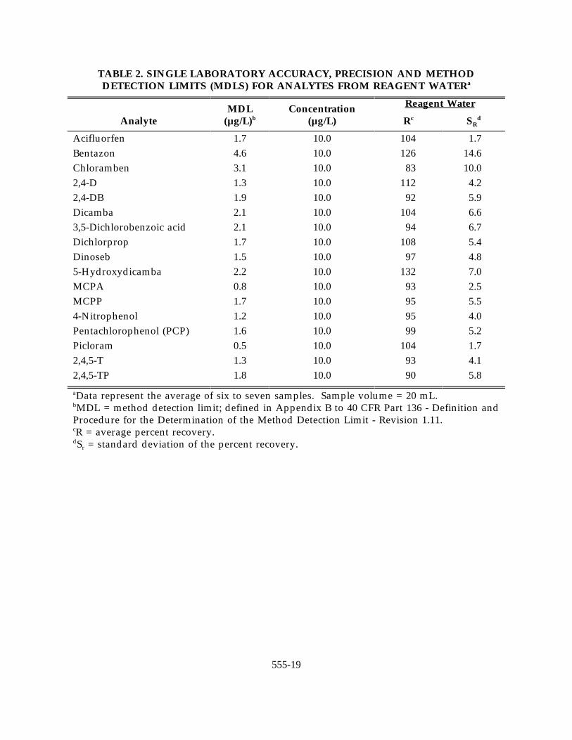
13.1 In a single laboratory, analyte recoveries from reagent water were determinedat two concentration levels. Results were used to determine analyte MDLs5
and demonstrated method range. Analyte MDLs and analyte recoveries andstandard deviations about the percent recoveries at one concentration are givenin Table 2.
13.2 In a single laboratory, analyte recoveries from dechlorinated tap water andground waters were determined at one concentration level, 10 ug/L. Resultswere used to demonstrate applicability of the method to different tap andground water matrices. Analyte recoveries from tap water and ground waterare given in Table 4. MDLs calculated from results of analyses of six 100 mLreagent water samples at 0.5 µg/L concentrations for each analyte are listed inTable 5.
14.0 POLLUTION PREVENTION
14.1 This method utilizes the new in-line liquid-solid extraction technology whichrequires the use of very small quantities of organic solvents. This featureeliminates the hazards involved with the use of large volumes of potentiallyharmful organic solvents needed for conventional liquid-liquid extractions.Also, this method uses no derivatizing reagents, which are toxic or explosive,to form gas chromatographable derivatives. These features make this methodmuch safer for use by the analyst in the laboratory and a great deal lessharmful to the environment.
14.2 For information about pollution prevention that may be applicable tolaboratory operations, consult "Less is Better: Laboratory ChemicalManagement for Waste Reduction," available from the American ChemicalSociety's Department of Government Relations and Science Policy, 1155 16thStreet N.W., Washington, D.C. 20036.

555-17
15.0 WASTE MANAGEMENT
15.1 Due to the nature of this method, there is little need for waste management. No large volumes of solvents or hazardous chemicals are used. The matricesof concern are finished drinking water or source water. However, the Agencyrequires that laboratory waste management practices be consistent with allapplicable rules and regulations, and that laboratories protect the air, water,and land by minimizing and controlling all releases from fume hoods andbench operations. Also, compliance is required with any sewage dischargepermits and regulations, particularly the hazardous waste identification rulesand land disposal restrictions. For further information on waste management,consult "The Waste Management Manual for Laboratory Personnel," alsoavailable from the American Chemical Society at the address in Section 14.2.
16.0 REFERENCES
1. Glazer, J.A., Foerst, D.L., McKee, G.D., Quave, S.A., and Budde, W.L. Environ.Sci. Technol. 15, 1981, pp. 1426-1435.
2. "Pesticide Methods Evaluation," Letter Report #33 for EPA ContractNo. 68-03-2697. Available from U.S. Environmental Protection Agency,Environmental Monitoring and Support Laboratory, Cincinnati, Ohio 45268.
3. ASTM Annual Book of Standards, Part 11, Volume 11.02, D3694-82, "StandardPractice for Preparation of Sample Containers and for Preservation," AmericanSociety for Testing and Materials, Philadelphia, PA, p. 86, 1986.
4. Giam, C.S., Chan, H.S., and Nef., G.S. "Sensitive Method for Determination ofPhthalate Ester Plasticizers in Open-Ocean Biota Samples," AnalyticalChemistry, 47, 2225 (1975).
5. 40 CFR, Part 136, Appendix B.

555-18
17.0 TABLES, DIAGRAMS, FLOWCHARTS, AND VALIDATION DATA
TABLE 1. RETENTION TIMES FOR METHOD ANALYTES
Analyte Group Primary Column Column
Retention Timesa
(minutes) Confirmation
Picloram (A) 19.0 12.85-Hydroxydicamba (A) 19.7 13.5Chloramben (A) 21.1 14.84-Nitrophenol (B) 21.6 5.0Dicamba (A) 24.0 18.2Bentazon (A) 25.2 19.5MCPA (B) 25.5 20.12,4-D (A) 25.6 20.13,5-Dichlorobenzoic acid (B) 26.7 21.3MCPP (B) 27.2 21.8Dichloroprop (A) 27.3 21.82,4,5-T (B) 27.5 22.42,4-DB (B) 28.0 22.82,4,5-TP (A) 29.2 23.9Acifluorfen (A) 30.7 25.5Dinoseb (B) 32.8 27.7Pentachlorophenol (B) 33.4 28.3
Columns and analytical conditions are described in Sections 6.4.1 and 6.4.2.a
555-19
TABLE 2. SINGLE LABORATORY ACCURACY, PRECISION AND METHODDETECTION LIMITS (MDLS) FOR ANALYTES FROM REAGENT WATERa
Analyte (µg/L) (µg/L) R SMDL Concentration
b
Reagent Waterc
Rd
Acifluorfen 1.7 10.0 104 1.7Bentazon 4.6 10.0 126 14.6Chloramben 3.1 10.0 83 10.02,4-D 1.3 10.0 112 4.22,4-DB 1.9 10.0 92 5.9Dicamba 2.1 10.0 104 6.63,5-Dichlorobenzoic acid 2.1 10.0 94 6.7Dichlorprop 1.7 10.0 108 5.4Dinoseb 1.5 10.0 97 4.85-Hydroxydicamba 2.2 10.0 132 7.0MCPA 0.8 10.0 93 2.5MCPP 1.7 10.0 95 5.54-Nitrophenol 1.2 10.0 95 4.0Pentachlorophenol (PCP) 1.6 10.0 99 5.2Picloram 0.5 10.0 104 1.72,4,5-T 1.3 10.0 93 4.12,4,5-TP 1.8 10.0 90 5.8
Data represent the average of six to seven samples. Sample volume = 20 mL.a
MDL = method detection limit; defined in Appendix B to 40 CFR Part 136 - Definition andb
Procedure for the Determination of the Method Detection Limit - Revision 1.11.R = average percent recovery.c
S = standard deviation of the percent recovery.dr

555-20
TABLE 3. CONFIRMATION WAVELENGTHS AND AREA RESPONSE RATIOS FORMETHOD ANALYTES
Analyte Wavelength (nm) RatioConfirmation Area Response
a
Acifluorfen 293 1.72Bentazon 240 1.08Chloramben 214 0.612,4-D 285 4.022,4-DB 285 5.93Dicamba 220 0.663,5-Dichlorobenzoic acid 285 5.15Dichlorprop 285 4.07Dinoseb 268 0.485-Hydroxydicamba 293 1.89MCPA 285 6.66MCPP 285 6.494-Nitrophenol 310 0.56Pentachlorophenol (PCP) 290 5.65Picloram 223 0.822,4,5-T 290 4.002,4,5-TP 293 3.84
Area Response Ratio = Peak Area for 230 nm/Peak Area for Conf. Wavelengtha

555-21
TABLE 4. SINGLE LABORATORY PRECISION AND ACCURACY DATA FROMTAP WATER AND GROUND WATERa
Dechlorinated
Tap Water Ground Water
Analyte R S R SbR
c bR
c
Acifluorfen 65.7 ±27. 87.3 ±17.Bentazon 86.1 ±6.0 90.1 ±9.0Chloramben 100 ±5.5 88.2 ±5.92,4-D 117 ±9.6 105 ±8.12,4-DB 91.2 ±7.0 97.2 ±6.1Dicamba 94.3 ±6.1 86.0 ±7.73,5-Dichlorobenzoic acid 90.2 ±7.2 92.1 ±5.5Dichlorprop 92.9 ±6.1 98.3 ±10.Dinoseb 94.1 ±6.2 91.2 ±4.15-Hydroxydicamba 110 ±5.5 108 ±7.0MCPA 92.7 ±5.0 85.2 ±5.7MCPP 91.4 ±7.7 84.3 ±5.94-Nitrophenol 89.2 ±10. 103 ±3.4Pentachlorophenol (PCP) 102 ±4.2 92.6 ±9.1Picloram 99.0 ±4.9 84.3 ±5.82,4,5-T 88.2 ±7.8 90.0 ±6.22,4,5-TP 90.3 ±5.9 77.8 ±8.9
Average of six samples fortified at 10 µg/L.a
Mean percent recovery, corrected for background levels.b
Standard deviation of the mean percent recovery.c

555-22
TABLE 5. SINGLE LABORATORY RECOVERY AND PRECISION DATA ANDMETHOD DETECTION LIMITS (MDLS) FOR ANALYTES FROM REAGENT WATERa
Analyte (µg/L) (µg/L) R SMDL Concentration
b
Reagent Waterc
Rd
Acifluorfen 0.40 0.5 114 23.7Bentazon 0.12 0.5 91 7.3Chloramben N.R. 0.5 N.R. N.R.2,4-D 0.34 0.5 121 20.22,4-DB 0.31 0.5 99 18.5Dicamba 0.24 0.5 80 14.13,5-Dichlorobenzoic acid 0.38 0.5 105 22.5Dichlorprop 0.33 0.5 110 19.4Dinoseb 0.26 0.5 99 15.55-Hydroxdicamba N.R. 0.5 N.R. N.R.MCPA 0.35 0.5 124 21.0MCPP 0.19 0.5 125 11.14-Nitrophenol N.R. 0.5 N.R. N.R.Pentachlorophenol (PCP) 0.15 0.5 93 8.6Picloram N.R. 0.5 N.R. N.R.2,4,5-T 0.21 0.5 80 12.72,4,5-TP 0.37 0.5 77 21.7
Data represent the average of six samples. Sample Volume = 100 mLa
MDL = Method detection limit; defined in Appendix B to 40 CFR 136 - Definition andb
Procedure for the Determination of the Method Detection Limit - Revision 1.11.R = Average percent recovery.c
S = Standard deviation of the percent recovery.dr
N.R. = Not Recovered.

555-23

555-24

555-25