determination of illite-smectite structures … 47/47-5-555.pdf · clays and clay minerals, vol....
TRANSCRIPT

Clays and Clay Minerals, Vol. 47, No. 5, 555-566, 1999.
D E T E R M I N A T I O N OF ILLITE-SMECTITE S T R U C T U R E S U S I N G MULTISPECIMEN X - R A Y D I F F R A C T I O N PROFILE FITTING
BORIS A. SAKHAROV, HOLGER LINDGREEN, 1 ALFRED SALYN, AND VICTOR m. DRITS
Institute of Geology, Russian Academy of Sciences, Pyzhevsky per D.7., 109017 Moscow, Russia Clay Mineralogical Laboratory, Geological Survey of Denmark and Greenland, Thoravej 8,
DK2400 Copenhagen NV, Denmark
Abst rae t - -A procedure for structural investigations by X-ray diffraction of mixed-layer structures incor- porating swelling layers has been developed. For each sample, specimens saturated with different cations (Na, Mg, and Ca), are analyzed both as air-dried and as glycolated. One structural model fitting all the observed patterns then provides the structure of the sample. Samples tested include: Illite-smectite (I-S) minerals from Kazachstan (a rectorite), Dolna Ves in Slovakia, Kinnekulle in Sweden, the North Sea, and Scania in Sweden. The fitting of the patterns of the Kazachstan rectorite demonstrated that the instrumental parameters applied in the modeling were correct. For the I-S minerals from Slovakia and Kinnekulle the observed patterns were fitted with one two-component I-S model. However, the Ca-saturated and air-dried specimen of the Kinnekulle bentonites had two types of swelling interlayers. For the Slovakian I-S with Reichweite = 2, an alternative two-phase I-S plus I-V (V = vermiculite) model fitted the experimental X-ray diffraction patterns equally well. The I-S mineral from Scania is in fact a three-component I-T-S (T = tobelite) and the North Sea sample is a four-component I-S-V-V', one type of the swelling layers having swelling characteristics intermediately between smectite and vermiculite. In addition to layer types and distribution, interlayer compositions, such as the amount of interlayer glycol and water and of fixed and exchangeable cations, were determined.
Key Words---lllite-Smectite, Simulation, Structure, Swelling, X-Ray Diffraction.
I N T R O D U C T I O N
Determinat ion of the structure of mixed- layer min- erals containing illite and swell ing layers is important because these are c o m m o n minerals and diagenesis and weathering changes their structure (Shutov et al., 1969a, 1969b; Perry and Hower, 1970; Weaver and Beck, 1971; Hower et al., 1976). By X-ray diffract ion (XRD), the interstratification of i l l i te-smecti te (I-S) minerals is usually est imated f rom peak-migrat ion curves showing the posit ion of basal reflections versus the proport ion and mode of interstratification of layer types in the mixed- layer structure (Drits and Sakharov, 1976; Srodofi, 1980, 1981, 1984; Watanabe, 1981, 1988; Reynolds , 1980, 1988; Tomita et al., 1988; Moore and Reynolds , 1989; Drits et al., 1994). The peak-migrat ion technique can, however , only be used for two-component I-S with random (R = 0, where R is the Reichwei te parameter) or m a x i m u m ordering for R = 1, 2, or 3, but not for I-S with segregated I or S layers or with intermediate degrees of ordering. Fur- thermore, peak-migrat ion curves have sofar mainly been used for g lycola ted I-S and are usual ly based on the assumption that all smecti te interlayers contain two glycol layers and that their swel l ing properties do not depend on the exchangeable cation. In addition, the mica layers are usually assumed to be K-bear ing and the thickness to be 9.98 or 10 ,~.
The most effect ive technique for determinat ion o f the structural parameters of mixed- layer minerals is based on compar ison be tween exper imental X R D
Copyright �9 1999, The Clay Minerals Society
curves and curves calculated for structural models having different proport ions and distributions of illite and smect i te layers (Reynolds and Hower, 1970; Drits and Sakharov, 1976; Reynolds , 1980; Moore and Reynolds , 1989; Drits and Tchoubar, 1990). However , the s imulat ion of X R D patterns requires many struc- tural and instrumental parameters (e.g., types, struc- tures, composi t ions, thicknesses, and distribution of layers; mean thickness and thickness distribution of coherent scattering domains (CSD); particle orienta- t ion; d ivergence of initial and diffracted X R D beams) which are known only approximately. For example, the swel l ing o f smect i te interlayers depends on the ex- changeable cations, the intercalated organic com- pounds, and the charge of the 2:1 layers, and these parameters require extens ive work to de termine (Brin- dley, 1966; M a c E w a n and Wilson, 1980; Drits et al., 1997a). The effect of these numerous variables is that several structural models may seem to fit the experi- mental data equal ly well, especial ly i f the exper imen- tal and calculated patterns are not superposed.
The goal o f this work is to demonstra te that deter- minat ion o f rel iable and detailed structural models for mixed- layer minerals can be obtained by the multi- spec imen profile fitting procedure: First, for the pattern of each specimen, close agreement be tween positions, intensities, and profiles of the reflections in the cal- culated and exper imenta l di f f ractograms must be ob- tained. Second, for one and the same sample, calcu- lated X R D patterns for one structural mode l must fit
555

556 Sakharov, Lindgreen, Salyn, and Drits Clays and Clay Minerals
the observed patterns of several specimens saturated with different exchangeable cations and examined both as air-dried and as glycolated. The principle of this multispecimen method is that each different treat- ment of the same sample is an independent test of the statistical structural model because each treatment changes the thickness and scattering efficiency of the swelling layers, but not the 2:1 layers and their distri- bution. Thus, structural parameters may be determined which are difficult or even impossible to obtain by current techniques. However, the present work dem- onstrates difficulties in the unambiguous determination of the actual structure of mixed-layer minerals, and I- S in particular.
MATERIALS AND METHODS
Samples
A rectorite-containing sample from the ore mine of Bestude, Kazachstan (Sakharov and Shlykov, personal communication); a hydrothermal sample DV2 from Slovakia (Sucha et al., 1992); two Kinnekulle benton- ites, B32 and B35 (Brusewitz, 1986); an illite-smec- tire-vermiculite (I-S-V) mixed-layer sample from the Upper Jurassic oil source rock from the Danish on- shore well Haldager 1, 1049 m depth (sample 95) and the North Sea well 2/11-1, 4548 m depth (sample 87); and an illite-tobelite-smectite (I-T-S) mixed-layer sam- ple from the Cambrian alum shale from *karpsm611e, Scania, Sweden, were investigated.
Sample preparation
The <0.1-1xm size fraction of DV2, the <0.2-p~m size fraction of the Kinnekulle bentonites, and the rec- torite sample were investigated. In shales, discrete il- lite is often present in addition to mixed-layer I-S (Reynolds and Hower, 1970; Hower et al., 1976; Na- dean and Reynolds, 1981). Thus, illite reflections may mask important features of the illite-smectite XRD pattern. Therefore, a special technique was used to iso- late a mixed-layer fraction from the Jurassic and Cam- brian shale samples. The samples were gently crushed to pass a 0.125-mm sieve. Chemical pretreatment in- volved using NaAc at pH 5.5 and 100~ to remove calcite, followed by NaOC1 at pH 9.0 and 100~ to remove organic matter (Anderson, 1963), and then Na- dithionite, bicarbonate and citrate at pH 7 to remove Fe- and Al-oxides (Mehra and Jackson, 1958), using --100 mg of dithionite per g of sample. The sand + silt fraction was then removed by centrifugation and the fine clay (<0.2 Ixm) and coarse clay (0.2-2 t~m) fractions were divided in a continuous-flow centrifuge. Because discrete illite and kaolinite were present in appreciable amounts even in the fine clay fraction of the shale, I-S-V was concentrated in an I-S-V fraction by the ethanol-water procedure of Buzagh and Szepesi (1955). This method was also used by Gibbs (1967)
for the separation of montmorillonite (see Hansen and Lindgreen, 1989). Based on scanning probe micros- copy the particles of this fraction are predominantly <500 A in diameter and <100 ,~ in thickness (Lind- green et al., 1992). The fraction is dominated by mixed-layer minerals; other minerals were removed.
Each sample was saturated with K +, Na +, NH], Mg 2+, and Ca 2+ using standard procedures. Oriented mineral aggregate specimens were prepared by the pi- pette method using 2.5 mg/cm 2 of specimen. The spec- imens were then treated with ethylene glycol vapor for 3 d at 60~
X-ray diffraction
XRD patterns were obtained using CuKo~ and CoK~t radiation with the DRON-4 and Philips PW1050 dif- fractometers, respectively. The DRON-4 diffractome- ter was supplied with a graphite monochromator and fine antiscatter slits (0.1-0.25 mm) to limit the hori- zontal beam divergence, along with soller slits having an angular aperture of 2.5 ~ to limit the vertical beam divergence. Intensities were measured for 100 s per 0.05 ~ step. The Philips diffractometer was supplied with Fe-filters and with 1/4 ~ fixed divergence and anti- scatter slits. Intensities were measured for 10 s per 0.1~ step. The XRD patterns were fitted within the 2.5-55 ~ region using the program of Drits and Sak- harov (1976). Corrections for instrumental variables including horizontal and vertical beam divergences, goniometer radius, dimensions and thickness of sam- pies followed the recommendations of Reynolds (1986) and Drits et al. (1993).
In the following, I, T, S, and V denotes illite, to- belite, smectite, and vermiculite-like or high-charge smectite layers, respectively, and wi, wij, Wtjk, etc. are the probabilities to find, respectively, a layer i, a layer pair ij, and a layer triple ijk. In addition, Pij denotes the conjunction probability for a layer j to follow a layer i and P~jk is the conjunction probability for a layer k to follow a layer pair ij (i, j, k = I, T, S, or V). Note that the use of simulations of XRD patterns permits us to determine the proportions and distribution of in- terlayers but not the layer types.
Structural models
Models for illite-containing 2:1 mixed-layer struc- tures have 2:1 layers separated by different types of interlayers. For 2:1 layers, z coordinates and site oc- cupancies given by Moore and Reynolds (1989, p. 321-322) were used. For most of the studied samples, the structure and composition of air-dried smectite in- terlayers containing different cations correspond to the one-dimensional structure of Moore and Reynolds (1989, p. 321-322). For the one and two-layer glycol complexes of smectite and vermiculite interlayers, the z coordinates and site occupancies of glycol molecules determined by Moore and Reynolds (1989, p. 321-

Vol. 47, No. 5, 1999 Multispecimen XRD profile fitting of I-S structures 557
Figure 1. Powder XRD patterns of the rectorite (Kazachs- tan) sample. Observed patterns: solid line; simulated: shaded line; d-values for simulated patterns in brackets. Oriented specimen, Mg2+-saturated and glycolated, CoKa radiation; a, b, c, and d show successive details of fit of 0-intervals of the complete pattern. Simulation was carried out with rectorite plus chlorite.
322) were used. The content of K in illite interlayers varied for different samples f rom 0.62 to 0.89 atoms per O10(OH)2. K, NH4, and Na cations were placed in the center of mica interlayers and thicknesses of illite
and tobeli te interlayers were 9.98 and 10.33 ,&, re- spect ively (Drits et al., 1997a), except for sample D V 2 where the thickness o f illite interlayers was 10.00 ,~. C S D thicknesses were log-normal ly distributed, the parameters o f this distribution were determined using a mean thickness of CSDs and the regression g iven by Drits et al. (1997b). The mean and m a x i m u m thick- nesses o f CSDs were variable parameters.
R E S U L T S
Rec tor i t e
Rectori te has a wel l -def ined mixed- layer structure with strict periodici ty along the c axis and many basal reflections. Rectori te was used to test the profile-fit t ing procedure since the chemical and structural parameters were well known. In the sample studied, rectori te with
chemical composi t ion (Nal.0o K0.13 Ca0.14 Mg0.08) (A14.0) (Si6.45A1~.55)O20 (OH)4 and d(001) = 26.65 A was mixed with a small amount of tr ioctahedral chlorite,
(All.80Mgz.45FeZ~0)(Siz.v0A1170)O10(OH)8 and d(001) = 14.125 A. The rectori te structure was constructed as an ordered alternation of 9.70-A paragonite layers
(Na0.87 K0.13 (Si3.00 All.00) A12.0o O10 (OH)z) with 16.95-,~ glycola ted smect i te layers, ((Mg0.08Na0.13Ca013)(Al2) (Si3.45A10.55)OI0(OH)z6.8(CH3OH)2.6H20). The glycer- ol-saturated smecti te inter layer contains in addit ion to the exchangeable cations two layers of glycerol mol- ecules whose z coordinates are g iven by Brindley (1966). Using the z coordinates of Rule and Bai ley (1987) for the structure o f chlori te with similar chem- ical composi t ion, the chlori te component was success- fully modeled. This mode led pattern was added to the rectori te pattern to obtain a comple te fit of the sample diffraction profile.
The exper imental and the calculated X R D patterns for the glycola ted rectori te are shown in Figure 1. A very good coincidence of positions, intensities, and profiles was achieved for 13 reflection orders of rec- torite and seven reflect ion orders of chlorite. The ac- curacy of the fitting procedure is demonstra ted by the sat isfactory agreement be tween the exper imental and calculated patterns for both the glycola ted and glycer- olated specimens. However , a small d isagreement be- tween the exper imental and calculated profiles (Figure la ) is observed for the low-angle part of the 001 rec- torite reflection, probably because the influence o f the instrumental factors and part icularly the Lorenz-polar- ization effects are not wel l mode led in this 0 region.
Samples B32 a n d B 3 5
The layer thicknesses, probabil i ty parameters, and the fitted X R D curves for the different specimens are shown in Figure 2.
For sample B32, the X R D patterns o f the M g and Na-saturated, air-dried and glycola ted specimens and the Ca-saturated and glycola ted specimens were suc-

558 Sakharov, Lindgreen, Salyn, and Drits Clays and Clay Minerals
Figure 2. Powder XRD patterns of Kinnekulle Bentonite B32. Observed and simulated patterns shown as solid and shaded lines, respectively; d-values for simulated patterns in brackets; I-S parameters presented above each pattern. Ori- ented specimens, CoKe~ radiation; a) Na+-saturated, air-dried, simulated with 2.75 H20 per O10(0H)2 (compare Figure 7), b) Na+-saturated and glycolated, c) Mg>-saturated and gly- colated, d) CaZ+-saturated and air-dried.
cessfully modeled with a two-component structure having wi = 0.60 and R = 0 (Figure 2a-2c). In con- trast, for the Ca-saturated and air-dried specimen, the best fit was obtained for a three-component model. This model has the same number of illite interlayers as the two-component model, and two types of swell- ing interlayers with thicknesses of 14.8 and 12.8 A in proportions 0.25 and 0.15, respectively (Figure 2d). In all models, illite interlayers contain 0.85 K per
Ore(OH)2. For sample B35, the same quality of fitting was ob-
tained for Na, Mg, and Ca-saturated specimens with w I = 0.48 and R = 0. As with sample B32, the Ca- saturated and air-dried specimen was fitted with a three-component structural model, but with 48% of 10-,~, 32% of 15.00-A, and 20% of 13.00-A layers.
Sample A
Application of I-S models with the usual 9.98 thickness of illite layers resulted in a large discrepancy between positions of the calculated and experimental 005 reflections, although the calculated and experi- mental peak intensities for 001,002, 003, and 004 co- incided for an I-S model with w~ = 0.95 and R = 0 (Figure 3a). In contrast, a model having Wl = 0.95, R = 0, and a mica-layer thickness of 10.05 ,~ resulted in satisfactory agreement between peak positions and intensities of all observed basal reflections (Figure 3b). The best fit was obtained for a three-component model in which 9.98-,~ illite, 10.32-,~ (or 10,35-A) tobelite or NH4-bearing mica, and smectite layers are inter- stratified with wl = 0.77, w t = 0.18, Ws = 0.05, and R = 0 (Figure 3c). The presence of NH4-bearing mica layers was supported by the infrared (IR) spectrum (strong absorption at 1430 cm -1) and by the XRD technique developed by Drits et al. (1997c and un- published data). The smectite interlayers may be dis- wibuted with R --> 1 but the XRD pattern is not sen- sitive to variations in order-disorder relating to the dis- tributions of the small amounts (0,05) of the smectite in this sample.
Sample D V2
For this sample, a one-phase, two-component; a one-phase, three-component; and a two-phase model were tested to obtain the best fit between the experi- mental and calculated patterns because the experimen- tal patterns deviated from the calculated patterns for the one-phase model at d-values of - 4 . 8 A.
Two-component model. The probability parameters, layer thicknesses, and the fits of the experimental air- dried and glycolated specimens saturated with the dif- ferent cations are given in Figure 4. The layer se- quence is characterized by near maximum possible de- gree of order for R = 2. Consequently, the layer pairs SS and triplets SSI and ISS are forbidden and the sub-

Vol. 47, No. 5, 1999 Multispecimen XRD profile fitting of I-S structures 559
Figure 3. Powder XRD patterns of shale from ~ m611e. Observed and simulated patterns shown as solid and shaded lines, respectively; d-values for simulated patterns in brackets; I-S parameters presented above each pattern, Oriented, Mg2+-saturated and glycolated specimen. CoK~x radiation, a)Interstratification of 9.98-A and 17.1-]~ lay- ers, b)Interstratification of 10.05-,~ and ol7.1-,~ layers, c) Interstratification of 9.98-,~, 10.35-A, and 17.1-A layers.
sequence SIS has a very low probability of occurrence. Illite interlayers have 0.85 of K per O10(OH)2. For the air-dried Na, Mg, and Ca-exchanged specimens, the calculated XRD curves reproduce positions, intensi- ties, and profiles of all basal reflections observed in the experimental XRD patterns (Figure 4a-4c). For the glycolated specimens saturated with Na, Mg, and Ca, the calculated XRD curves show a good fit in position, intensity, and profile of each basal reflection except for those with d - 4.8 ]1. For this peak, the experi- mental curve is significantly higher than the calculat-
ed, but this difference decreases from Mg to Ca-ex- changed specimens (Figure 4d-4f). Changes in com- position, structure, proportion, and distribution of gly- col-containing smectite interlayers failed to improve the agreement between the observed and the calculated intensities within the 20 region of 20.6-22.8 ~ For ex- ample, an increase in number of glycol molecules in- creases the intensity of the peak with d - 4.8 ]1, but decreases the intensity of the reflections with d - 5.18 ]1. Similar disagreement for the same diffraction re- gion was observed previously for I-S with R -> 1 (Reynolds, 1980; McCarty and Thompson, 1991). Therefore, more complicated structural models were tested.
Three-component models. It was assumed that the gly- colated specimens, in addition to 17-]1 smectite layers, contain small amounts of 13-]1 vermiculite layers. The amount of illite layers was assumed to be the same as for the two-component model (wi = 0.84). As little as 0.03 vermiculite layers improved significantly the agreement between calculated and experimental max- ima in the region 10-11 ~ However, the presence of vermiculite layers significantly shifts the two reflec- tions in the calculated pattern at small-angle relative to the observed peaks. Therefore, this model was re- jected.
A physical mixture of two mixed-layer phases. For gly- colated specimens we assume that one interstratified phase produces strong peaks with d(001) = 9.6-9.7 ]1 and 5.1-5.2 ]1, and a second phase shows peaks with d(001) = 11.8-12.1 and 4.7-4.8 ]1 (Figure 5). A mix- ture of I-S and I-V phases shows these peaks: the I-S phase consists of 10.00-]1 illite and 16.9-]1 or 17.0-]1 smectite layers with w~ = 0.82, Pss = 0, Ps~s = 0.1, R = 2, and the I-V phase of 10.00-]1 illite and 13.6-]1 vermiculite layers with one layer of glycol molecules and wl = 0.65 or 0.70, Pvv = 0, R = 1. Calculated pattems for such I-S and I-V mixed in a ratio of 0.7: 0.3 provides better agreement with the maxima of the observed patterns in the region 10-11 ~ in compari- son with the single two-component model. This model for an I-S and I-V mixture simulates the major dif- fraction features of the XRD profile for the Mg, Ca, and Na-exchanged, air-dried or glycolated specimens (Figure 5).
Sample 87
Specimens saturated with Mg, Ca, Na, and NH 4 and both air-dried and glycolated were investigated. Layer thicknesses, probability parameters, and the fitted XRD patterns are shown in Figure 6. For all speci- mens, the structure model has three components, one non-swelling and two swelling. For the Ca, Mg, and Na-saturated specimens, the structure has 10.03-]t il- lite layers with wi = 0.80. In Mg or Ca-saturated spec- imens, both glycolated or air-dried, the two swelling

560 Sakharov, Lindgreen, Salyn, and Drits Clays and Clay Minerals
Figure 4. Powder XRD patterns of hydrothermal sample DV2 (Slovakia) simulated as a one-phase I-S. Observed and simulated patterns shown as solid and shaded lines, respectively; d-values of simulated patterns in brackets; I-S parameters are presented above each pattern. Oriented specimens, CoKa radiation; a) Na+-saturated, air-dried, b) Ca2+-saturated and air- dried, c) Mg2+-saturated and air-dried, d) Na+-saturated and glycolated, e) Ca2+-saturated and glycolated, f) Mg2+-saturated and glycolated.
components are present in proportions of 0.12 and 0.08 (Figure 6a and 6b) and in the Na-saturated and glycolated specimen in proportions of 0.02 and 0.18 (Figure 6c). The structural models for the Ca, Mg, and Na-saturated, air-dried specimens have 14.0-,~ and 12,5-]k expandable layers in proportions of 0.12 and 0.08 (Mg-saturated, Figure 6b), 0.10 and 0.10 (Ca- saturated), and 0.06 and 0.14 (Na-saturated, Figure 6d), respectively. For the NHa-saturated, air-dried specimen, the amount of non-swelling layers is 0.90, but 0.10 of these layers have d(001) = 10.33 A. For all models of this sample, the layer types are distrib- uted a t R = 1.
It is remarkable that the largest part of the swelling component expands to 17.1 A in the glycolated and Mg and Ca-saturated specimens, but only to 13.35 ,~
in the glycolated and Na-saturated specimen. For air- dried specimens, the proportion of layers swelling to 14.0 ,~ decreases from the Mg-saturated to the Ca- saturated and further to the Na-saturated specimen, The relative humidity in the laboratory was 30-40%.
DISCUSSION
The results show that observed XRD patterns of I- S and I-S-V minerals saturated with different cations and prepared in air-dried and glycolated states can be accurately fitted. However, the multispecimen ap- proach reveals problems in the structural study of these minerals.
Reliability o f structural and instrumental parameters
If one set of probability parameters can be used to obtain a satisfactory simulation of experimental XRD

Vol. 47, No. 5, 1999 Multispecimen XRD profile fitting of I-S structures 561
Figure 5. Powder XRD patterns of hydrothermal sample DV2 (Slovakia) simulated as a two-phase mixture of I-S and I-V in the ratio of 2.3:1.0. Observed and simulated patterns shown as solid and shaded lines, respectively; d-values of simulated patterns in brackets; I-S and I-V parameters are presented above each pattern. Oriented specimens, CoKa ra- diation; a) Na+-saturated, air-dried b) Na+-saturated and gly- colated, c) Ca2§ and glycolated, d) Mg2+-saturated and glycolated.
Figure 6. Powder XRD patterns of North Sea Upper Juras- sic shale sample from well 2/11-1, 4548 m depth (sample 87). Observed and simulated patterns shown as solid and shaded lines, respectively; d-values of simulated patterns in brackets, I-S-V parameters above each pattern. Oriented spec- imens; a) Mg2+-saturated and glycolated, CuKet radiation; b) Mg2+-saturated and air-dried; CoKct radiation; c) Na+-satu - rated and glycolated, CoKtx radiation; d) Na+-saturated, air- dried, CoK0~ radiation.
562 Sakharov, Lindgreen, Salyn, and Drits Clays and Clay Minerals
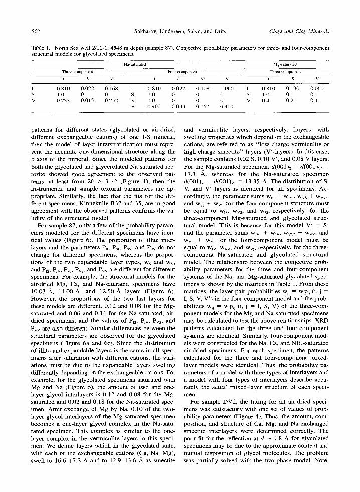
Table 1. North Sea well 2/11-1, 4548 m depth (sample 87). Conjective probability pm'ameters for three- and four-component structural models for glycolated specimens.
Na-saturated Mg-saturated
Three-component Four-component Three-component
I S V I S V' V I S V
I 0.810 0.022 0.168 I 0.810 0.022 0.108 0.060 I 0.810 0.130 0.060 S 1.0 0 0 S 1.0 0 0 0 S 1.0 0 0 V 0.733 0.015 0.252 V' 1.0 0 0 0 V 0.4 0.2 0.4
V 0.400 0.033 0.167 0.400
patterns for different states (glycolated or air-dried, different exchangeable cations) of one I-S mineral, then the model of layer interstratification must repre- sent the accurate one-dimensional structure along the c axis of the mineral. Since the modeled patterns for both the glycolated and glycerolated Na-saturated rec- torite showed good agreement to the observed pat- terns, at least from 20 > 3-4 ~ (Figure 1), then the instrumental and sample textural parameters are ap- propriate. Similarly, the fact that the fits for the dif- ferent specimens, Kinnekulle B32 and 35, are in good agreement with the observed patterns confirms the va- lidity of the structural model.
For sample 87, only a few of the probability param- eters modeled for the different specimens have iden- tical values (Figure 6). The proportion of illite inter- layers and the parameters Ptt, Psi, Pss, and Psv do not change for different specimens, whereas the propor- tions of the two expandable layer types, Ws and Wv, and Pls, Pw, Pvl, Pvs, and Pvv are different for different specimens. For example, the structural models for the air-dried Mg, Ca, and Na-saturated specimens have 10.03-/k, 14.00-,~, and 12.50-,~ layers (Figure 6). However, the proportions of the two last layers for these models are different, 0.12 and 0.08 for the Mg- saturated and 0.06 and 0.14 for the Na-saturated, air- dried specimens, and the values of P~s, Pw, Pvs, and Pvv are also different. Similar differences between the structural parameters are observed for the glycolated specimens (Figure 6a and 6c). Since the distribution of illite and expandable layers is the same in all spec- imens after saturation with different cations, the vari- ations must be due to the expandable layers swelling differently depending on the exchangeable cations. For example, for the glycolated specimens saturated with Mg and Na (Figure 6), the amount of two and one- layer glycol interlayers is 0.12 and 0.08 for the Mg- saturated and 0.02 and 0.18 for the Na-saturated spec- imen. After exchange of Mg by Na, 0.10 of the two- layer glycol interlayers of the Mg-saturated specimen becomes a one-layer glycol complex in the Na-satu- rated specimen. This complex is similar to the one- layer complex in the vermiculite layers in this speci- men. We define layers which in the glycolated state, with each of the exchangeable cations (Ca, Na, Mg), swell to 16.6-17.2 A and to 12.9-13.6 ,~ as smectite
and vermiculite layers, respectively. Layers, with swelling properties which depend on the exchangeable cations, are referred to as "low-charge vermiculite or high-charge smectite" layers (V'-layers). In this case, the sample contains 0.02 S, 0.10 V', and 0.08 V layers. For the Mg-saturated specimen, d(001)s = d(001)v, = 17.1 ,~, whereas for the Na-saturated specimen d(001)v = d(001)v, = 13.35 ,~. The distribution of S, V, and V' layers is identical for all specimens. Ac- cordingly, the parameter sums wls + wlv,, Wvs + Wvv,, and Wsi + Wv,~ for the four-component structure must be equal to W~s, Wvs, and Wsl, respectively, for the three-component Mg-saturated and glycolated struc- tural model. This is because for this model V' = S; and the parameter sums W~v, + W~v, Wvv, + Wvv, and Wv,1 + Ww for the four-component model must be equal to wlv, Wvv, and Wvt, respectively, for the three- component Na-saturated and glycolated structural model. The relationship between the conjective prob- ability parameters for the three and four-component systems of the Na- and Mg-saturated glycolated spec- imens is shown by the matrices in Table 1. From these matrices, the layer pair probabilities wij = w~p~j (i, j = I, S, V, V') in the four-component model and the prob- abilities wij = w~p,j (i, j = I, S, V) of the three-com- ponent models for the Mg and Na-saturated specimens may be calculated to test the above relationships. XRD patterns calculated for the three and four-component systems are identical. Similarly, four-component mod- els were constructed for the Na, Ca, and NH4-saturated air-dried specimens. For each specimen, the patterns calculated for the three and four-component mixed- layer models were identical. Thus, the probability pa- rameters of a model with three types of interlayers and a model with four types of interlayers describe accu- rately the actual mixed-layer structure of each speci- men.
For sample DV2, the fitting for all air-dried speci- mens was satisfactory with one set of values of prob- ability parameters (Figure 4). Thus, the amount, com- position, and structure of Ca, Mg, and Na-exchanged smectite interlayers were determined correctly. The poor fit for the reflection at d -- 4.8 A for glycolated specimens may be due to the approximate content and mutual disposition of glycol molecules. The problem was partially solved with the two-phase model. Note,

Vol. 47, No. 5, 1999 Multispecimen XRD profile fitting of I-S structures 563
however, that very different models may equally well describe the main diffraction features of the observed patterns for the different treatments. Indeed, the two- component I-S model is very different from the mix- ture of I-S and I-V. However, apart from the reflection of d -- 4.86 A, both models produce similar XRD patterns. Thus, for sample DV2, the structure cannot be determined unambiguously by this method.
Accuracy in determination o f probability parameters
Reflection intensities are sensitive to small varia- tions of probability parameters and especially to the proportions of interlayers (Drits et al., 1997a). For the Mg-saturated and glycolated sample 87, a change in w~ from 0.80 to 0.78 or 0.82 results in a marked dif- ference between calculated and observed intensities at least for the first peak (Drits et al. 1997a). Thus, if the calculated and observed patterns fit well, then the error in amount of layer types probably is <0.02. For the air-dried, Na and Mg-saturated specimens of sample DV2 the best fit was obtained with wi = 0.84, whereas for the Ca-saturated and glycolated specimen the best fit was achieved with wt = 0.82 (the decrease of 10.00- ,& layers by 0.02 results in a marked improvement in the fit for this specimen). Thus, the proportion of illite interlayers in this sample is equal to 0.84 --- 0.02. For all air-dried and for the Ca-saturated and glycolated specimen, Ps~s = 0.10 whereas the Mg and Na-satu- rated and glycolated models have PSlS = 0.05 and 0, respectively (Figure 4d-4f). However, the quality of the fit varied for the different glycolated specimens (Figure 4d-4f). Thus, for this sample, the probability parameters for the air-dried specimens were deter- mined with greater reliability and precision than those of the glycolated specimens.
Composition of interlayers
The structure and composition of expandable inter- layers in I-S and I-S-V minerals are important for clay- water interaction and thus for swelling properties, and water absorption and desorption of these minerals. Ac- cording to Srodofi et al. (1986), illite interlayers in 1- S from sandstone, K- bentonites, and hydrothermal de- posits contain 0.89 K per O10(OH)2. Based on this as- sumption, they proposed a technique for determining mean thickness of illite fundamental particles by using the expandability of I-S minerals,
One advantage of the fitting procedure is the pos- sibility to determine interlayer composition and layer sequences for a mixture of I-S or I-S-V with other minerals. For the hydrothermal sample DV2 and the bentonite samples B32 and B35, the illite interlayers contain 0.85 K per O10(OH)2 in agreement with Srodori et al. (1986). For I-S and I-S-V of North Sea Jurassic and Baltic Cambrian shales, however, the K content in illite interlayers is significantly lower and equal to 0.75 atoms per O10(OH)2, as for samples 95 and A. More-
over, for the diagenetically transformed shale sample A, the fitting procedure reveals interstratification of K and NH4-bearing mica interlayers with the ratio 0.80: 0.15. Drits et al. (1997c) proposed a technique for de- termining the amount and distribution of fixed K and NH4 in I and I-S minerals using the d-values and the full width at half height (FWHH) values of d(002) and d(005) of the K-saturated and heated specimens. For the K-saturated and heated sample A, d(001) = 5 X d(005) = 10.031 A and FWHH(005)/FWHH(002) = 1.284. Accordingly, 15% of 10.33-A NHa-bearing il- lite layers are interstratified with 85% of 9.98-.~ K- bearing layers. Based on the fitting, these are 80% of 9.98-.~ illite and 5% dehydrated K-saturated smectite layers. It is remarkable that the proportions of NH4 in the I-S-V found by the two different approaches are identical. For the diagenetically transformed shale sample 87, simulation shows a composition of 20% expandable interlayers and 0.675 K per O10(OH) 2 in the mica interlayers. Drits et al. (1997c) showed that this sample contains 14% of NH4-bearing mica inter- layers interstratified with K-bearing mica and expand- able interlayers. Thus, the ratio of the interstratified K and NH4-bearing mica interlayers is equal to 0.825: 0.175. Using the scattering power of K and NH4 as 18 and 10 electronsL~, respectively, the K in the illite interlayers is calculated from the equation: 0.675 = (18 x 0.825 x c~ + 10 X 0.175)/18. The cK in illite interlayers is equal to 0.70 K which is similar to the 0.75 for sample 95 and A.
Thus, in conclusion, determination of illite funda- mental particle thicknesses based on XRD expand- ability and the fixed amount of K in illite interlayers needs further refinement for shale I-S and I-S-V min- erals. Also, special attention is required for the effec- tive thickness of mica layers in I-S and I-S-V in oil- bearing rocks.
The number of water molecules in smectite inter- layers saturated by different exchangeable cations is different for different I-S or I-S-V and the fitting pro- cedure may be used to determine this parameter. At- tempts to get a satisfactory fit of sample B32 (Na- saturated, air-dried) with models using the one-dimen- sional structure for smectite interlayers as proposed by Moore and Reynolds (1989) failed (Figure 7). The best fit was obtained for smectite interlayers containing 2.75 water molecules per O10(OH)2. Thus, water mol- ecules in smectite interlayers of the I-S structure of sample B32 form a hexagonal planar network where these molecules are separated by --3.0 A For gly- colated interlayers, the fitting procedure applied to the I-S-V of sample 87 confirmed that the amount of gly- col molecules in the one-layer glycol interlayer of the vermiculite component is equal to two molecules per O10(OH)2, the amount given by Moore and Reynolds (1989).

564 Sakharov, Lindgreen, Salyn, and Drits Clays and Clay Minerals
Figure 7. Powder XRD pattern of Kinnekulle Bentonite B32. Observed and simulated patterns shown as solid and shaded lines, respectively; d-values of simulated pattern in brackets, I-S parameters above pattern, Oriented specimen, Na+-saturated, air-dried, simulated with 1.0 H20 per O10(OH)2 (compare Figure 2a). CoKa radiation.
Figure 8. Powder XRD patterns of Danish onshore Upper Jurassic shale sample from well Haldager 1, 1049 m depth (sample 95). Observed and simulated patterns shown as solid and shaded lines, respectively; d-values of simulated patterns in brackets; I-S-V parameters are given in matrix. Oriented specimen, Mg2+-saturated and glycolated. CuKa radiation.
Segregation of interstratified layer types
Drits and Sakharov (1976) calculated XRD patterns for I-S in which interstratification of illite and smectite layers changed from random alternation to full segre- gation via intermediate segregated structures. They concluded that XRD patterns for I-S with a significant tendency to segregation are quite similar to XRD pat- terns from a physical mixture of illite and smectite or illite and I-S. Probably for this reason, at present, it is commonly accepted that alternation of illite and smec- tite interlayers is random or has some tendency to or- der but not segregation. From the characteristics of the XRD pattern of Mg-saturated and glycolated sample 95 (Figure 8), the sample may consist of a physical mixture of smectitic, illitic, and kaolinitic phases. In- deed, the diffraction maxima with d-values of 10.0, 5.03, 3.359, and 1.994.4, correspond to an illitic phase containing a small amount of swelling layers, and these layers may explain the small deviation from the d-values of a rational series. If the peak migration curves constructed by Sr0dofi (1984) are applied to the interpretation of these data, then the illitic phase should contain 0% of smectite interlayers. The strong peak with d = 17.1 A might correspond to a smectite phase. An alternative interpretation of the XRD pattern is that sample 95 is a mixture of isolated illite and randomly ordered I-S particles. In this case, the posi- tion (20 - 15.9 ~ of the shoulder from the low-angle side of the reflection with d = 5.03 .~ (Figure 8) should be considered. Using the technique of Srodofi (1980), the content of swelling ~ interlayers in the I-S is equal to 90%, if the 3.359-A reflection belongs to I-S, and the thickness of the glycolated smectite layers is 16.8 ,~.
Attempts to obtain a satisfactory fit for these two- phase models were unsuccessful. However, a satisfac- tory agreement (Figure 8) between the observed and calculated profiles was achieved for the I-S-V one-
phase models where the layer types have a significant tendency to segregation with the short-range ordering of R = 1.
The degree of segregation for each type of layer may be estimated by the expression: Si = (Pii - Wi)/ (1 - w~), where i = I, S, or V. Accordingly, for Pii =
1 then S = 1, and the sample contains a phase con- sisting only of layers of type i. For Pii = Wi and S~ = 0, the layers of type i are randomly distributed among the other layer types. For the I-S-V structure of sample 95 the degree of segregation for illite, smectite, and vermiculite layers is: Si = 0.35, Ss = 0.23, and Sv = 0.47. The values for wi and Pii ( i = I , S, o r V) are given in Figure 8. The values of S~ show that the ten- dency to segregation is different for different layers. These values increase from smectite to vermiculite layers. The significant tendency of vermiculite layers to segregation was found also for the diagenetically transformed North Sea sample 87. As noted from the probability parameters given in Figure 6a and 6b, this I-S-V structure has Sv = 0.35. Segregated I-S and I- S-V are probably more common in shales than as- sumed at present. Distinguishing the mineral mixtures of illite and I-S, or of illite and smectite, from the I- S-V structure having segregated layer types is impor- tant for evaluating the parent material and the diage- netic processes.
CONCLUSIONS
The multispecimen method provides one structural model for all samples investigated except for sample DV2, where two different models fitted all observed patterns nearly equally well. Application of the meth- od provides detailed data on the one-dimensional structure for two, three, and four-component systems and on interlayer composition. Thus, interpretation of XRD data from dioctahedral mica-smectite minerals requires analysis of positions as well as of intensities

Vol. 47, No. 5, 1999 Multispecimen XRD profile fitting of I-S structures 565
of all basal reflections in the obse rved X R D patterns and the interpretat ion of X R D pat terns o f g lycola ted samples may be in error i f it is based on the quali tat ive analysis of a single X R D pat tern f rom a Na-saturated sample.
A C K N O W L E D G M E N T S
We are grateful to NATO for the Linkage Grant HTECH.LG and to the Danish Natural Science Research Council for the grant 9601518 without which this investiga- tion would not have been possible. V.A. Drits, B.A. Sakharov, and A. Salyn are grateful to the Russian Science Foundation for financial support.
R E F E R E N C E S
Anderson, J.U. (1963) An improved pretreatment for miner- alogical analysis of samples containing organic matter. Clays and Clay Minerals, 10, 380-388.
Brindley, G.W. (1966) Ethylene glycol and glycerol complex- es of smectites and vermiculites. Clay Minerals, 6, 237- 259.
Brusewitz, A.M. (1986) Chemical and physical properties of Palaeozoic bentonites from Kinnekulle, Sweden. Clays and Clay Minerals', 34, 442-454.
Buzagh, W. and Szepesi, K. (1955) A colloid-chemical meth- od for the determination of the montmorillonite content in bentonites. Acta Chimica Hungarica, 5, 287-298.
Drits, V.A. and Sakharov, B.A. (1976) X-ray Analysis of Mixed-layer Minerals. Nauka, Moskow, 256 pp. (in Rus- sian).
Drits, V.A. and Tchoubar, C. (1990) X-ray Diffraction by Dis- ordered Lamellar Structures. Springer Verlag, Berlin, 371 pp.
Drits, V.A., Weber, E, Salyn, A.L., and Tsipursky, S.I. (1993) X-ray identification of one-layer illite varieties: Application to the study of illites around uranium deposits, Canada. Clays and Clay Minerals, 41, 389-394.
Drits, V.A., Varaxina, T.V., Sakharov, B.A, and Plan~on, A. (1994) A simple technique for identification of one-dimen- sional powder X-ray diffraction patterns for mixed-layer illite-smectites and other interstratified minerals. Clays and Clay Minerals, 42, 382-390.
Drits, V.A., Sakharov, B.A., Lindgreen, H., and Salyn, A. (1997a) Sequential structure transformation of illite-smec- tite-vermiculite during diagenesis of Upper Jurassic shales from the North Sea and Denmark. Clay Minerals, 32, 351- 371.
Drits, V.A., Srodofi, J., and Eberi, D.D. (1997b) XRD mea- surement of mean crystallite thickness of illite and illite/ smectite: Reapparisal of the Kubler index and the Scherrer equation. Clays and Clay Minerals, 45, 461-475.
Drits, V.A., Lindgreen, H., and Salyn, A. (1997c) Determi- nation by X-ray diffraction of content and distribution of fixed ammonium in illite-smectite. Application to North Sea illite-smectites. American Mineralogist, 82, 79-87.
Gibbs, R.J. (1967) Quantitative X-ray diffraction analysis us- ing clay mineral standards extracted from the samples to be analysed. Clay Minerals, 7, 79-90.
Hansen, RL. and Lindgreen, H. (1989) Mixed-layer illite/ smectite diagenesis in Upper Jurassic claystones from the North Sea and onshore Denmark. Clay Minerals, 24, 197- 213.
Hower, J., Eslinger, E.V., Hower, M.E., and Perry, E.A. (1976) Mechanism of burial metamorphism of argillaceous sediments. Geological Society of America Bulletin, 87, 725-737.
Lindgreen, H., Garnaes, J., Besenbacher, E, Laegsgaard, E., and Stensgaard, I. (1992) Illite-smectite from the North Sea investigated by scanning tunneling microscopy. Clay Min- erals, 27, 331-342.
MacEwan, D.M.C. and Wilson, M.J. (1980) Interlayer and intercalation complexes of clay minerals. In Crystal Struc- tures of Clay Minerals and Their X-ray Identification, G.W. Brindley and G. Brown, eds., Mineralogical Society, Lon- don, 197-248.
McCarty, D.K. and Thompson, G.R. (1991) Burial diagenesis in two Montana Tertiary basins. Clays and Clay Minerals, 39, 293-305.
Mehra, O.P. and Jackson, M.L. (1958) Iron oxide removal from soils and clays by a dithionite-citrate buffered with sodium carbonate. Clays and Clay Minerals, 7, 317-327.
Moore, D.M. and Reynolds, R.C. (1989) X-ray Diffraction and the Identification and Analysis of Clay Minerals, Ox- ford University Press, Oxford.
Nadeau, RH. and Reynolds, R.C. (1981) Burial and contact metamorphism in the Mancos shale. Clays and Clay Min- erals, 29, 249-259.
Perry, E. and Hower, J. (1970) Burial diagenesis in Gulf Coast pelitic sediments. Clays and Clay Minerals, 18, 165- 177.
Reynolds, R.C. (1980) Interstratified clay minerals. In Crystal Structures of Clay Minerals and Their X-ray Identification, G.W. Brindley and G. Brown, eds., Mineralogical Society, London, 249-304.
Reynolds, R.C. (1986) The Lorenz-polarization factor and preferred orientation in oriented clay aggregates. Clays and Clay Minerals, 34, 359-367.
Reynolds, R.C. (1988) Mixed-layer chlorite minerals. In Hy- drous Phyllosilicates (Exclusive of Micas), Reviews in Min- eralogy, Volume 19, S.W. Bailey, ed., Mineralogical Soci- ety of America, Chelsea, Michigan, 601-630.
Reynolds, R.C. and Hower, J. (1970) The nature of interlay- ering in mixed-layer illite-montmorillonite. Clays and Clay Minerals, 18, 25-36.
Rule, A.C. and Bailey, S.W. (1987) Refinement of the crystal structure of a monoclinic ferroan clinochlore. Clays and Clay Minerals, 35, 129-138.
Shutov, V.D., Drits, V.A., and Sakharov, B.A. (1969a) On the mechanism of a postsedimentary transformation of mont- morillonite into hydromica. In Proceedings of the Inter- national Clay Conference, Tokyo, 1969, Volume 1, L. Hell- er, ed., Jerusalem, 523-532.
Shutov, V.D., Drits, V.A., and Sakharov, B.A. (1969b) On the mechanism of a postsedimentary transformation of mont- morillonite into hydromica: Discussion. In Proceedings of the International Clay Conference, Tokyo, 1969, Volume 2, L. Heller, ed., Jerusalem, 126-129.
Srodofi, J. (1980) Precise identification of illite/smectite in- terstratifications by X-ray powder diffraction. Clays and Clay Minerals, 28, 401-411.
Srodofi, J. (1981) X-ray identification of randomly interstrat- ified illite/smectite in mixtures with discrete illite. Clay Minerals, 16, 297-304.
Srodofi, J. (1984) X-ray powder diffraction identification of illific materials. Clays and Clay Minerals, 32, 337-349.
Srodofi, J., Elsass, E, McHardy, W.J., and Morgan, D.J. (1986) Chemistry of illite/smectite inferred from TEM measurements of fundamental particles. Clay Minerals, 27, 137-158.
Sucha, V., Kraus, I., Mosser, C., Hroncova, Z., and Siranova, V. (1992) Mixed-layer illite/smectite from the Dovna Ves hydrothermal deposit, the western Carpathians Kremnica MTS, Bratislava. Geologia Carpathica, Clays, Series 1, 1, 13-21.

566 Sakharov, Lindgreen, Salyn, and Drits Clays and Clay Minerals
Tomita, K., Takahashi, H., and Watanabe, T. (1988) Quanti- fication curves for mica/smectite interstratifications by X- ray powder diffraction. Clays and Clay Minerals, 36, 258- 262.
Watanabe, T. (1981) Identification of interstratifications of il- lite and montmorillonite by X-ray powder diffraction. Jour- nal of the Mineralogical Society Japan, 15, 32-41. (in Jap- anese).
Watanabe, T. (1988) Structural model of illite/smectite inter- stratified minerals and the diagram for their interstratifica- tion. Clay Science, 7, 97-114.
Weaver, C.E. and Beck, K.C. (1971) Clay water diagenesis during burial: How mud becomes gneiss. Geological So- ciety of America Special Paper, 134, 1-78.
(Received t April 1998; accepted 28 October 1998; Ms. 98-041)