methanol as an energy carrier · pdf filemethanol as an energy carrier ... 4.2 methanol from...
TRANSCRIPT
EnergietechnikEnergy Technology
Methanol as an Energy Carrier
Peter Biedermann, Thomas Grube, Bernd Höhlein (Hrsg.)
Methanol as an Energy Carrier
Peter Biedermann, Thomas Grube, Bernd Höhlein (Hrsg.)

Schriften des Forschungszentrums JülichReihe Energietechnik / Energy Technology Band / Volume 55


Schriften des Forschungszentrums JülichReihe Energietechnik / Energy Technology Band / Volume 55
ISSN 1433-5522 ISBN 3-89336-446-3
Forschungszentrum Jülich GmbHInstitut für Werkstoffe und Verfahren der Energietechnik (IWV)IWV-3: Energieverfahrenstechnik
Methanol as an Energy Carrier
Peter Biedermann, Thomas Grube,Bernd Höhlein (Hrsg.)
Bibliographic information published by Die Deutsche Bibliothek.Die Deutsche Bibliothek lists this publication in the DeutscheNationalbibliografie ; detailed bibliographic data is available in theInternet at <http://dnb.ddb.de>.
Publisher Forschungszentrum Jülich GmbHand Distributor: Zentralbibliothek, Verlag
52425 JülichPhone: +49 2461 61-5368 · Telefax: +49 2461 61-6103e-mail: [email protected]: http://www.fz-juelich.de/zb
Cover Design: Grafische Betriebe, Forschungszentrum Jülich GmbH
Printer: Grafische Betriebe, Forschungszentrum Jülich GmbH
Copyright: Forschungszentrum Jülich 2006
Schriften des Forschungszentrums JülichReihe Energietechnik / Energy Technology Band / Volume 55
ISSN 1433-5522ISBN-10: 3-89336-446-3ISBN-13: 978-3-89336-446-6
Neither this book nor any part of it may be reproduced or transmitted in any form or by anymeans, electronic or mechanical, including photocopying, microfilming, and recording, or by anyinformation storage and retrieval system, without permission in writing from the publisher.
Authors
Chapter 1: Bernd Höhlein, Forschungszentrum Jülich GmbH 1 Wolfgang Seuser, De Witt & Co Inc. Europe, Hus-ton/Texas
Chapter 2–4: Bernd Höhlein, Forschungszentrum Jülich GmbH 1 Thomas Grube, Peter Biedermann, Forschungszentrum Jülich GmbH
Chapter 3.4: Jürgen Mergel, Hendrik Dohle, Forschungszentrum Jü-lich GmbH
Chapter 5: Jens R. Rostrup-Nielsen, Haldor Topsøe A/S, Lyngby, Denmark
Chapter 6.1–6.5: Ib Dybkjær, Torben Topsøe A/S, Lyngby, Denmark
Chapter 6.6-6.7: John Bøgild Hansen, Haldor Topsøe A/mark
Chapter 7: Hubert Bielawa, Lurgi Öl•Gas•Chemfurt/Main (2003), Waldemarfurt/Main (2006)
Chapter 8: Bernd Höhlein, Forschungszentrum Jülich Gmb
Chapter 8.5: Detlef Stolten, PeteJülich GmbH
Chapter 9: Georg Erdmann, Technische UniversitäLudmilla Schlecht, Technische Universi
Chapter 10: Gerhard Isenberg, Raphael Edinger, DaimlerChrysler AG, Stuttgart
Chapter 11: Peter Biedermann, Forschungszentrum Jülich GmbH
Chapter 11.3: Martin Pokojski, Uwe Radke, BEWAG AG Berlin 2
Chapter 12: Bernd Höhlein, Forschungszentrum Jülich GmbH 1
Editorial
1
2 Rena
Anglo-Saxon units of measurement
The Anglo-Saxon units of measurement commonly used in the respective subject area have not been converted into the SI system, but conversion and estimation aids are provided.
Trademarks
The abbreviations used with ® or ™ in the text are trademarks of the companies Haldor Topsøe AS, Lurgi AG and Volkswagen AG respectively, which stand for a technical process.
Preface
The present volume is based on volume 28 “Methanol als Energieträger” (Methanol as an Energy Carrier) published in the Energy Technology series in 2003 (ISBN 3-89336-338-6). It has above all been supplemented by additional contributions to the chapters on DMFC and methanol prepara-tion:
– DMFC (Chapter 3)
– Synthesis gas (Chapter 5)
– Process engineering of methanol synthesis (Chapter 6)
– Methanol and MCFC (Berlin project) (Chapter 11.3)
The chapters of the 2003 editon have been updated. However, this was not possible in each case for costs or prices because of the dramatic price increases at the end of 2005.
The editors would like to thank Ms M. Heinz from the Language Service at the Central Library of Research Centre Jülich for the translation of the German text into English and for useful advice.

vii
Contents
0 Contents
0 Contents.................................................................................. vii
0.1 Figures and Tables............................................................ xii
0.1.1 Figures......................................................................... xii
0.1.2 Tables ......................................................................... xiv
0.2 Abstract ........................................................................ xvii
1 Introduction .............................................................................. 1
1.1 Fuel supply for the transport sector...................................... 1
1.2 Global situation of methanol................................................ 3
1.3 Summary of Chapter 1 ....................................................... 6
2 Possible energy carriers for road traffic ......................................... 9
2.1 Costs and emissions..........................................................10
2.2 Summary of Chapter 2 ......................................................13
3 Methanol and alternative fuels for road traffic ...............................14
3.1 Methanol for MTBE production ............................................17
3.2 M85 for direct-injection combustion engines .........................17
3.3 Methanol for fuel cells with reformers ..................................19
3.4 Methanol for fuel cells without reformers (DMFC) .................25
3.4.1 Fuel for direct fuel cells...................................................26
3.4.2 Principle of the DMFC .....................................................27
3.4.3 Development areas ........................................................28
3.4.3.1 Electrode structure ...................................................30
3.4.3.2 New membrane materials ..........................................31
3.4.3.3 Selective catalysts ....................................................32
3.4.4 Applications ..................................................................33
3.4.5 Outlook ........................................................................34
3.5 Methanol for fuel cell powered passenger cars in the USA.......34
3.6 Summary of Chapter 3 ......................................................35
4 Methanol production..................................................................36
4.1 Methanol from natural gas .................................................37
4.1.1 Synthesis gas production ................................................37
4.1.2 Methanol synthesis.........................................................38
4.1.3 Life cycle cost and energy balance....................................39
viii
Contents
4.2 Methanol from coal ...........................................................41
4.3 Summary of Chapter 4 ......................................................43
5 Synthesis gas ..........................................................................44
5.1 Applications .....................................................................44
5.1.1 Principles......................................................................44
5.1.2 Natural gas conversion ...................................................44
5.1.3 Coal conversion .............................................................46
5.2 Synthesis gas technologies ................................................47
5.2.1 Steam reforming............................................................48
5.2.2 CO2 reforming ...............................................................51
5.3 Synthesis gas for methanol ................................................53
5.3.1 Stoichiometry................................................................53
5.3.2 Choice of technology ......................................................54
5.4 Direct conversion..............................................................55
5.5 Summary of Chapter 5 ......................................................56
6 Process engineering of methanol synthesis ...................................58
6.1 Methanol production technology..........................................58
6.2 Synthesis gas preparation .................................................59
6.2.1 One-step reforming........................................................60
6.2.2 Two-step reforming........................................................61
6.2.3 Autothermal reforming ...................................................63
6.2.4 Gas-heated reforming.....................................................64
6.2.5 Choice between reforming technologies.............................65
6.2.6 Gasification ...................................................................66
6.2.7 Co-production of methanol in ammonia plants ...................67
6.3 Methanol synthesis ..........................................................67
6.3.1 Thermodynamics ...........................................................67
6.3.2 Catalysts ......................................................................68
6.3.3 Reaction mechanism ......................................................68
6.3.4 Kinetics ........................................................................69
6.3.5 By-products ..................................................................70
6.3.6 Design of methanol synthesis reactors ..............................71
6.3.6.1 Quench reactor ........................................................71
6.3.6.2 Adiabatic reactor ......................................................72
ix
Contents
6.3.6.3 Boiling water reactor.................................................72
6.3.6.4 Gas-cooled reactor ...................................................72
6.3.6.5 Integrated gas-cooled reactor ....................................73
6.3.6.6 Radial flow reactor....................................................73
6.3.6.7 Slurry phase reactor .................................................73
6.3.7 Condensing methanol .....................................................74
6.4 Methanol purification ........................................................74
6.4.1 Low-grade methanol ......................................................74
6.4.2 High-grade methanol......................................................75
6.4.2.1 Two-column distillation..............................................75
6.4.2.2 Three-column distillation ...........................................75
6.5 Dimethyl ether technologies ..............................................76
6.5.1 Methanol dehydration .....................................................77
6.5.2 Combined synthesis .......................................................77
6.5.3 Catalysts ......................................................................78
6.5.3.1 Dehydration catalysts ...............................................79
6.5.3.2 Catalysts used in integrated technologies.....................79
6.6 Methanol reforming in water gas shift reactors .....................80
6.6.1 Thermodynamics ...........................................................80
6.6.2 The kinetics of methanol reforming in low-temperature water gas shift reactors ..................................................81
6.6.3 Industrial applications ....................................................82
6.6.4 Economic considerations .................................................84
6.6.5 Conclusions...................................................................85
6.7 Use of methanol and DME in solid oxide fuel cell systems ......85
6.7.1 Introduction ..................................................................85
6.7.2 Methanol-based SOFC systems with methanol methanation..................................................................86
6.8 Summary of Chapter 6 ......................................................88
7 Methanol technologies ..............................................................89
7.1 Natural gas-to-methanol....................................................89
7.1.1 The concept ..................................................................89
7.1.2 Synthesis gas production ................................................89
7.1.3 Autothermal reforming ...................................................90
x
Contents
7.1.4 Combined reforming.......................................................90
7.1.5 Methanol production.......................................................92
7.1.6 Methanol distillation .......................................................95
7.1.7 Evaluation of economic efficiency .....................................95
7.2 Dimethyl ether .................................................................96
7.2.1 Production process .........................................................97
7.2.2 Evaluation of economic efficiency .....................................98
7.3 Methanol-to-hydrogen.....................................................100
7.4 Synthetic fuels ...............................................................102
7.5 Summary of Chapter 7 ....................................................106
8 Hazard potentials of methanol ..................................................109
8.1 Safety...........................................................................110
8.2 Environmental impacts due to leakages .............................111
8.3 Human health ................................................................111
8.4 Filling stations................................................................112
8.5 Comparison with possible direct fuel cell fuels.....................112
8.6 Summary of Chapter 8 ....................................................115
9 Methanol for the chemicals market ...........................................116
9.1 Global production capacities .............................................116
9.2 Global demand for methanol ............................................117
9.3 Prospects for global methanol demand...............................119
9.4 Methanol trading ............................................................120
9.5 Methanol prices ..............................................................122
9.6 Future development ........................................................123
9.7 Summary of Chapter 9 ....................................................124
10 Biofuel projects ...................................................................125
10.1 Overview.......................................................................125
10.2 Production paths for biofuels ............................................126
10.3 Motivation for the use of biomass as an energy carrier.........128
10.4 Status of biogenic methanol production .............................129
10.5 EU proposal for biofuel market launch ...............................130
10.6 Energy crops in the EU: necessary agricultural areas ...........130
10.7 Biomass from waste and biogenic residues for fuel production ...............................................................131
xi
Contents
10.8 EU resources for fuel production from renewables ...............133
10.9 Fuel production costs ......................................................133
10.10 Biomass projects ............................................................135
10.11 Summary of Chapter 10 ..................................................136
11 Special aspects ....................................................................137
11.1 Fuel cells for portable applications.....................................137
11.2 Ban on MTBE .................................................................138
11.3 Berlin methanol fuel cell project .......................................139
11.4 Summary of Chapter 11 ..................................................142
12 Summary............................................................................143
13 Literature............................................................................146
13.1 Literature used...............................................................146
13.2 Further literature ............................................................164
14 Annex.................................................................................166
14.1 Supplementary tables .....................................................166
14.2 Abbreviations, explanations, conversions ...........................168
14.2.1 Abbreviations ..............................................................168
14.2.2 Definitions / explanations..............................................171
14.2.3 Chemical compounds....................................................176
14.2.4 Specification of quantities .............................................177
14.2.5 Conversion of units ......................................................177
14.2.6 Estimation of units .......................................................177
15 Keywords............................................................................178
xii
Contents
0.1 Figures and Tables
0.1.1 Figures
Figure 1: Synthesis gas derived alternative fuels from fossil and renewable sources ................................................. 3
Figure 2: Fuel energy costs and greenhouse gas emissions ............12
Figure 3: Pathways of using synthesis gas from natural gas............14
Figure 4: Fuel cell power train with on-board hydrogen production from methanol ............................................20
Figure 5: Reduction potential of future vehicle/fuel systems (passenger car) in relation to primary energy input and climate-relevant emissions .....................................25
Figure 6: Principle of the DMFC ..................................................26
Figure 7: Cell voltage and power density of a DMFC at 80°C...........29
Figure 8: Specific methanol permeability and cell voltage of a sulphonated PEK (sPEK) membrane (80°C, 1 M methanol, 3 bar).........................................................31
Figure 9: Oxygen reduction at the cathode: electrochemical activity of various catalyst materials (wt% of cathode material) in the presence (+) / absence (-) of methanol ...................................................................32
Figure 10: DMFC vehicle JuMOVe (Research Centre Jülich)...............33
Figure 11: Methanol production with combined reforming ................39
Figure 12: Process steps: methanol and gasoline from coal ..............41
Figure 13: Hydrogen by air-blown reforming for CO2-free power production .................................................................46
Figure 14: IGCC power plant combined with production of chemicals ..................................................................47
Figure 15: Steam reforming and methane conversion......................48
Figure 16: Reformer furnace. Waste heat section............................49
Figure 17: ATR reactor................................................................50
Figure 18: H2/CO ratios from different syngas processes..................52
Figure 19: Module M and H2/CO in raw gas from ATR ......................53
Figure 20: Impact of economy of scale..........................................54

xiii
Contents
Figure 21: Synthesis gas plant of 2,500 MTPD methanol plant, Statoil, Tjeldbergodden................................................55
Figure 22: Recycle ratio and conversion ........................................56
Figure 23: Methanol production by one-step reforming – simplified process flow diagram.....................................61
Figure 24: Methanol production by two-step reforming – simplified process flow diagram.....................................62
Figure 25: Methanol production by ATR at low S/C ratio. Adjustment of synthesis gas composition by hydrogen recovery and recycling. Simplified flow diagram.....................................................................64
Figure 26: Gas-heated reforming in combination with ATR ...............65
Figure 27: Co-production of methanol in ammonia plant. In-line facility. Simplified flow diagram.....................................66
Figure 28: Most abundant surface species found on methanol synthesis catalysts ......................................................69
Figure 29: Methanol distillation with two concentration columns – simplified process flow diagram..................................75
Figure 30: Combined synthesis of methanol and DME – simplified process flow diagram.....................................78
Figure 31: Temperature, CO and methanol profiles in shift reactor ......................................................................82
Figure 32: Revamp of hydrogen plant by Methanol-to-Shift™ ...........83
Figure 33: Effect of capacity utilisation ..........................................84
Figure 34: Process scheme of a MeOH-based SOFC systems with MeOH methanation .....................................................87
Figure 35: Methanol production by Combined Reforming..................91
Figure 36: Two-stage methanol synthesis using the MegaMethanol® process ...............................................92
Figure 37: Temperature profiles of two-stage methanol synthesis using the MegaMethanol® process....................93
Figure 38: Two-stage methanol synthesis with 3-column distillation..................................................................94
Figure 39: DME production from crude methanol ............................97
Figure 40: Comparison of DME with diesel and LPG.........................99
Figure 41: MTH® process ...........................................................100
xiv
Contents
Figure 42: Gas-based refinery via methanol: Lurgi’s
MtSynfuels® ............................................................104
Figure 43: Lurgi’s gas-to-chemicals processing routes (GTC®) .......107
Figure 44: Global market shares of methanol capacities according to regions in December 2001........................116
Figure 45: Cost structure of methanol in comparison to the price of methanol in Europe (quarters of the years 2000 to 2002)......................................................................121
Figure 46: CO2 reduction due to power train developments and renewable fuels ........................................................127
Figure 47: Necessary EU agricultural area to reach the EU biofuel targets with energy crops ................................131
Figure 48: Possible technically usable alternative potentials for biofuels in the EU......................................................132
Figure 49: Fuel production costs in €-cents/kWh before taxes after 2010 ...............................................................134
Figure 50: Fuel production costs for waste wood and energy crops in €-cents/kWh before taxes ..............................134
Figure 51: The Carbo-V® process for the conversion of solid
biomass feedstocks into a synthesis gas for fuels production ...............................................................136
Figure 52: MCFC Hot Module (internal reforming) .........................140
Figure 53: Components of the MCFC system for methanol operation.................................................................141
0.1.2 Tables
Table 1: Global methanol supply and demand 2005–2008, quantities/million tons .................................................. 6
Table 2: Analysis of energy carrier costs (2000–2003)..................11
Table 3: Specific fuel costs in Germany ......................................12
Table 4: Specific fuel taxes in Germany without VAT (of early 2003) ...........................................................13
Table 5: Energy, efficiency and CO2 balances of full fuel cycles for compact passenger cars..........................................24

xv
Contents
Table 6: Performance targets for fuel cell systems .......................29
Table 7: Methanol: feedstocks and potential use..........................36
Table 8: Various specifications for methanol................................37
Table 9: Investment costs for a plant .........................................39
Table 10: Balances for methanol supply from natural gas ...............40
Table 11: Potentials for methanol production from coal ..................42
Table 12: Comparison of balances for methanol production from coal and residual oils and from natural gas (basis: LHV)...............................................................43
Table 13: Synthesis gas reactions for methane conversion..............48
Table 14: Syngas composition for various processes ......................52
Table 15: Elementary steps of the microkinetic model ....................70
Table 16: Typical by-product formation ........................................71
Table 17: Use of DME and market share.......................................76
Table 18: Operating conditions before and after revamp by installation of Methanol-to-Shift™ .................................83
Table 19: Changes in total production and consumption figures .......84
Table 20: Economic efficiency of steam reforming plants ................95
Table 21: Comparison of DME and diesel fuel ................................96
Table 22: Comparison of DME and LPG.........................................96
Table 23: Economic efficiency of the MegaDME process ..................98
Table 24: DME compared with diesel and LPG 2006 .......................99
Table 25: Economic efficiency of the MTH® process......................101
Table 26: Comparison of synthetic fuels .....................................103
Table 27: Comparison of capital and cost estimates for synthetic fuels ..........................................................106
Table 28: Comparison of market prices for synthetic fuels ............106
Table 29: Properties of methanol, methane and hydrogen in comparison to gasoline ..............................................109
Table 30: Methanol in comparison with possible direct fuel cell fuels .......................................................................113
Table 31: European methanol production: capacities and changes 1990–1999 ..................................................117
Table 32: Methanol imports to EU and EFTA states in the years 1991 and 2000, quantities/kt......................................120
xvi
Contents
Table 33: EU target quotas in per cent for renewable and biogenic fuels ...........................................................130
Table 34: Technically usable potentials for biomass from waste in Germany and in the EU ..........................................132
Table 35: Compilation of the Lurgi processes mentioned here........166
Table 36: Henry coefficients for some substances ........................166
Table 37: CO2 balances for different processes for the production of energy carriers......................................167
Table 38: Lower heating values and specific densities of some energy carriers .........................................................167
xvii
Abstract
0.2 Abstract
For the future, a strongly growing energy demand is expected in the transport sector worldwide. Economically efficient oil production will run through a maximum in the next decade. Higher fuel prices and an envi-ronmentally desirable reduction of emissions will increase the pressure for reducing fuel consumption and emissions in road traffic. These criteria show the urgent necessity of structural changes in the fuel market.
Due to its advantages concerning industrial-scale production, storage and global availability, methanol has the short- to medium-term potential for gaining increased significance as a substitution product in the energy market. Methanol can be produced both from fossil energy sources and from biomass or waste materials through the process steps of synthesis gas generation with subsequent methanol synthesis.
Methanol has the potential to be used in an environmentally friendly man-ner in gasoline/methanol mixtures for flexible fuel vehicles with internal combustion engines and in diesel engines with pure methanol. Further-more, it can be used in fuel cell vehicles with on-board hydrogen produc-tion in direct methanol fuel cell drives, and in stationary systems for elec-tricity and heat generation as well as for hydrogen production. Finally, in portable applications it serves as an energy carrier for electric power gen-eration.
In this book, the processes for the production and use of methanol are presented and evaluated, markets and future options are discussed and issues of safety and environmental impacts are addressed by a team of well-known authors.

1
Introduction
1 Introduction
Methanol as a chemical raw material has long been a marketable product. About 15–20 years ago, however, Californian initiatives already aimed at minimizing traffic-induced smog situations especially in Southern Califor-nia by the use of clean energy carriers such as methanol. This has led to considerations and initial attempts to provide filling stations for metha-nol/gasoline mixtures (85/15) and correspondingly adapted Otto engines for the market. Since the automobile market is oriented globally, there have been relevant activities worldwide and thus also in Germany with the first filling stations and vehicles. In the 1990s, these efforts were not fur-ther pursued, but instead methanol became a potential fuel for fuel cell vehicles (FCVs) in combination with on-board reformers for hydrogen pro-duction. A first filling station for FCVs was built within the framework of the California Fuel Cell Initiative and the first vehicles, such as Daimler-Chrysler's “NECAR 5”, were developed and put on the road.
Methanol as an energy carrier for road traffic involves the following crite-ria: lower tank-to-wheel emissions, producible from fossil and biomass-based primary energies, handling of a normally liquid energy carrier with known infrastructures and safety constraints. These criteria are important for building up future energy supply structures for globally increasing transport and traffic along with fewer oil-based fuels and more syntheti-cally produced fuels including also methanol.
1.1 Fuel supply for the transport sector
For the future, a strongly growing energy demand is expected in the transport sector, which will still largely be covered by crude oil coming mainly from the Middle East. Economically efficient oil production will run through a maximum in the next decade. This situation of future fuel sup-ply is likely to produce instabilities in ecological, economic and political re-spects. Expanding natural gas markets will in future primarily have to make use of the great reserves in the Middle East (Iran, Qatar, Saudi Ara-bia) and the Russian Federation [SCHMITZ 2002]. Higher fuel prices and an environmentally desirable reduction of traffic-induced climate-relevant and locally effective emissions with their secondary pollutants will increase the pressure for reducing fuel consumption and emissions in road traffic. The essential motivation for the envisaged structural changes in the transport sector can be defined as follows:
2
Introduction
– improvement of local and regional air quality,
– restricting global warming,
– less dependence on oil.
These changes will have to be accomplished by an increase in the effi-ciency of “clean” drive systems and a market launch of fuels with suffi-cient economical availability, which – including their use in motor vehicles – will contribute towards reducing the emissions in the transport sector.
Future fuel supply is evaluated according to the following criteria:
– availability and range of energy carrier resources (fossil / renewable),
– infrastructure requirements,
– evaluation of fuel supply in terms of energy,
– pollutant and greenhouse gas emissions of the full fuel cycle (local / re-gional / global),
– potential for forming secondary pollutants,
– fuel supply costs,
– fuel specifications,
– impacts on safety, environment, health and acceptance.
In the medium- to long-term perspective, new final energy carriers for motor vehicles will be produced on a fossil and increasingly on a renew-able basis. In order to utilize them – in addition to further developed in-ternal combustion engines – hybrid vehicles, electrically driven battery vehicles and electrically driven fuel cell vehicles will also have to be taken into consideration in future.
Final energy carriers, which can be simultaneously used both for conven-tional drives and for new drives with fuel cells and which in the long term are produced on the basis of renewable sources of primary energy, will have good prospects for future application. An increased incorporation of renewable energy sources in the future presupposes adequate availability at competitive costs and the creation of new infrastructures [ED-INGER/ISENBERG/HÖHLEIN 2003].
Figure 1 shows possible pathways of future fuel supply on a synthesis gas (syngas) basis. Natural gas or associated gas, coal and biomass are suit-able feedstocks for the production of synthetic liquid energy carriers. Sub-sequently to a synthesis gas (H2, CO, CO2) production process, Fischer-Tropsch diesel, methanol or hydrogen or substitute natural gas (SNG) can be produced.

3
Introduction
Figure 1: Synthesis gas derived alternative fuels from fossil and renewable sources
This would require new production capacities and for methanol and hydro-gen also new infrastructures. The production of these energy carriers is also possible on the basis of biomass. One then speaks of biomass-to-
liquid (BTL) or SunFuel® for synthetic liquid fuels in addition to vegetable oil methyl esters (FAME) and bioalcohols (ethanol). A use of synthetic en-ergy carriers based on synthesis gas is basically possible in both combus-tion-engine and fuel-cell drives.
Due to its advantages concerning industrial-scale preparation, storage and global availability, methanol and also synthetic liquid fuels have the short- to medium-term potential for gaining increased significance as a substitu-tion product in the energy market.
1.2 Global situation of methanol
Traditionally, methanol is a chemical base material mainly produced from natural gas today and forms the basis for the production of formaldehyde, MTBE and acetic acid; these three products cover about two thirds of the total methanol demand.
The synthesis gas produced from natural gas, coal or biomass opens up prospects for new production possibilities of methanol and new products
COCO2
H2 CO2
Natural Coalgas Biomass
GasificationReformation
CO2-free power generationPre-combustion + CO2 capture
CO2-freepower generation:
Synthesis gas (H2, CO2, CO)
Heterogeneous catalysis & synthesis
H2 separation & conditioning
Electrolysis
Natural Synfuelsgas SunFuel®
CO2 sequestration
Methanol SNG ElectricityHydrogen
4
Introduction
such as synthetic fuels, hydrogen and indirectly also electricity (Figure 1).
These prospects and the well-founded interest in their further develop-ment have meanwhile led to various pilot plants aiming at a future com-mercialization and enhancement of these technologies.
At present, there is still a lack of goal-oriented driving forces in the mar-ket enabling further implementation. The dominance of oil and the associ-ated trends in the market constitute a barrier that is difficult to overcome.
We can at present only take a stance on the development of prices for the traditional chemical application of methanol. Pricing will probably change fundamentally if methanol were to become an energy carrier one day.
The demand for methanol grows with the gross national product (GNP). This basic experience plays an essential role in demand coverage and thus in the estimation of prices.
2003 production capacities amount to 36.7 million tons worldwide. This figure reflects the nominal capacity; real production is in the range of 85% (historical average of capacity utilization) of this capacity value. Modern plants are definitely able today to increase this output to 90% or more.
The global demand for the calendar year 2004 was approx. 34 million tons compared to a production of approx. 33 million tons. Even if certain stocks are included, a bottleneck in the availability of methanol must be ex-pected. This is due to the fact that in the past two years no new produc-tion capacity has come onto the market. The price level has developed ac-cordingly; methanol is currently experiencing an unparalleled historical boom.
The new and first methanol megaplant with a nameplate capacity of 1.65 million tons located in Trinidad started production in quarter 3 of 2004, however with some technical difficulties, which were solved over 2005. It is to be expected that this plant will reach full capacity throughout 2006.
In October 2005 another site with 2.0 million tons came on stream in Trinidad, working sufficiently from the very beginning.
In 2005 and 2006 prices for methanol were still soaring because of tight-ness of production. The new plants were not able to compensate the clo-sures of older and ineffective working plants. The exploded high gas prices led one European producer with a capacity of approx. 950,000 MT per year to unexpectedly close the plant by mid-2006, having reduced produc-tion effectively by 50% by quarter 4 of 2005.

5
Introduction
Due to the reduction of MTBE production, approx. 2.5 million tons of methanol will be additionally available on the world market in the same period.
However, these volumes became free step by step und were nearly all swallowed by annual global demand increasing by 4–5% in that period, especially by permanently increased consumption in China.
In 2007 and thereafter a relaxation of the market is expected, because then some new capacity will start production located in Iran, China and Saudi Arabia, followed by investments in Oman. 6.0–6.5 million tons of additional methanol are expected to be probably available to the con-sumer up to 2008.
It is remarkable to note that investments in increasingly larger plants are being made. Today’s megaplant of 1.65 million tons capacity per year (5,000 tons per day) is becoming a standard. The first plant of this type is named Atlas, is located in the Caribbean and is just about to go into op-eration. Another plant of this design was to follow in Iran in 2005 (LURGI).
The published investment activities will lead to a change of the flow of commodities/supplies of methanol on the world market.
In the Caribbean, where approximately 2.8 million tons of methanol were produced in 2004, new plants will increase the output to approx. 6.5 mil-lion tons per year. In Chile, 4 million tons will then be produced instead of 3 million tons per year today.
This means that approximately 3.5 million tons of methanol will be addi-tionally produced in the logistically favourable neighbourhood of America. On the American mainland, in contrast, those production facilities are lo-cated which are unprofitable even today due to the development of the gas costs. These plants are threatened with closure, and there is a closure potential of as much as 3.5 million tons in total.
Great attention must be paid to the investments in the eastern part of the world. Oman, Qatar, Saudi Arabia and above all Iran could in total pro-duce approx. 15 million tons of methanol in 2010 compared to a capacity of approximately 6 million tons today. However, due to new estimates it could be possible that not all expected new capacity will become commer-cial and available for the market. It has to be admitted that the invest-ments, especially the capacities in Iran, could also be used for captive ap-plication and DME. This possible local consumption will reduce the volume for commercialization.
6
Introduction
Owing to these new capacities, both Europe and the Asian area can be supplied much more favourably than is the case today due to new logistic challenges and efforts.
All the new production facilities have a lot in common; they produce methanol where the gas deposit is located and they have favourable gas conditions in the long term that ensure a profitable production of metha-nol in the long term.
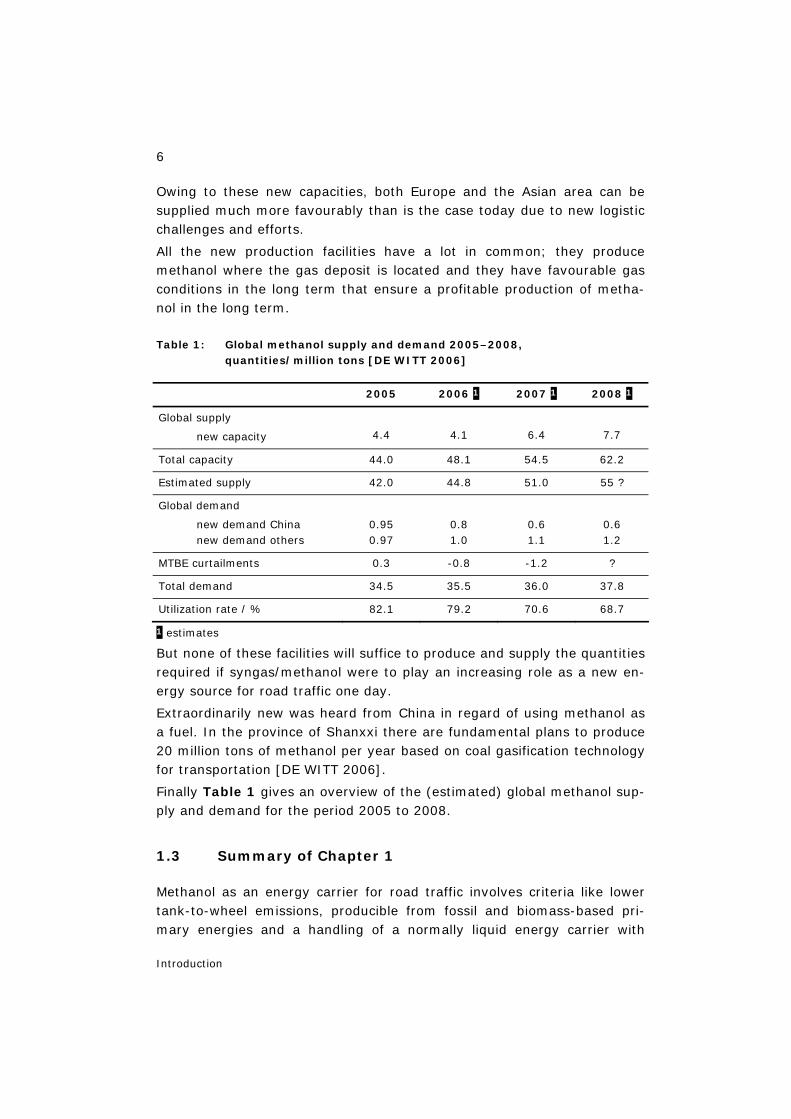
Table 1: Global methanol supply and demand 2005–2008, quantities/million tons [DE WITT 2006]
2005 2006 1 2007 1 2008 1
Global supply
new capacity
4.4
4.1
6.4
7.7
Total capacity 44.0 48.1 54.5 62.2
Estimated supply 42.0 44.8 51.0 55 ?
Global demand
new demand China new demand others
0.95 0.97
0.8 1.0
0.6 1.1
0.6 1.2
MTBE curtailments 0.3 -0.8 -1.2 ?
Total demand 34.5 35.5 36.0 37.8
Utilization rate / % 82.1 79.2 70.6 68.7
1 estimates
But none of these facilities will suffice to produce and supply the quantities required if syngas/methanol were to play an increasing role as a new en-ergy source for road traffic one day.
Extraordinarily new was heard from China in regard of using methanol as a fuel. In the province of Shanxxi there are fundamental plans to produce 20 million tons of methanol per year based on coal gasification technology for transportation [DE WITT 2006].
Finally Table 1 gives an overview of the (estimated) global methanol sup-ply and demand for the period 2005 to 2008.
1.3 Summary of Chapter 1
Methanol as an energy carrier for road traffic involves criteria like lower tank-to-wheel emissions, producible from fossil and biomass-based pri-mary energies and a handling of a normally liquid energy carrier with
7
Introduction
known infrastructures and safety constraints. For the future, a strongly growing energy demand is expected in the transport sector. Higher fuel prices and an environmentally desirable reduction of traffic-induced cli-mate-relevant and locally effective emissions with their secondary pollut-ants will increase the pressure for reducing fuel consumption and emis-sions in road traffic. These challenges will have to be met by an increase in the efficiency of “clean” drive systems. In the medium- to long-term perspective, new final energy carriers for motor vehicles will be produced on a fossil and increasingly on a renewable basis.
Natural gas or associated gas as well as coal or biomass are suitable via synthesis gas for the production of synthetic liquid energy carriers – Fischer-Tropsch diesel as synfuel, methanol or hydrogen or for substitute natural gas. This would require new production capacities and for metha-nol and hydrogen also new infrastructures. These energy carriers can also be produced on the basis of biomass. One then speaks of biomass-to-liquid (synthetic) fuels. A use of synthetic energy carriers is basically pos-sible in both combustion-engine and fuel-cell drives.
Traditionally, methanol is a chemical base material mainly produced from natural gas today and forms the basis for the production of formaldehyde, MTBE and acetic acid; these three products cover about two thirds of the total methanol demand. Synthesis gas produced from natural gas, coal or biomass opens up prospects for new production possibilities of methanol and new products such as synthetic fuels, hydrogen and indirectly also electricity. These prospects and the well-founded interest in their further development have meanwhile led to various pilot plants.
The demand for methanol grows with the gross national product. This ba-sic experience plays an essential role in demand coverage and thus in the estimation of prices. At present we only can take a stance on the devel-opment of prices for the traditional chemical application of methanol. Pric-ing will probably change fundamentally if methanol were to become an energy carrier one day.
In 2005 and 2006 prices for methanol were still soaring. High gas prices exploded. MTBE production was reduced. China shows a permanently in-creasing consumption. In 2007 and thereafter a relaxation of the market is expected.
Investments in increasingly larger plants are being made but it could be possible, that not all expected new capacity will become commercial and available for the market. All the new production facilities produce metha-

8
Introduction
nol where the gas deposit is located and they have favourable gas condi-tions in the long term.
None of these facilities will suffice to produce and supply the quantities required if syngas/methanol were to play an increasing role as a new en-ergy source for road traffic one day.
9
Possible energy carriers for road traffic
2 Possible energy carriers for road traffic
From the analysis of the interrelation of energy use and environmental impacts, the following statements can be derived concerning the energy carriers for road traffic:
– Road traffic mainly causes emissions of carbon monoxide (CO), hydro-carbons (CnHm) and nitrogen oxides NOx) and is thus also responsible for the formation of summer smog (ozone, formaldehyde and other secondary pollutants).
– The increasing introduction of three-way catalytic converters for pas-senger cars reduces the legally regulated emissions from passenger cars, but not those from commercial vehicles; problematic local / re-gional immission areas are still possible. CO2 emissions from traffic are rising.
– Various measures in fuel and engine technology are suitable to improve the conventional drive systems in road traffic and thus quantitatively reduce the emissions polluting the environment.
– A great potential for emissions reduction is provided by new energy car-riers such as natural gas, methanol (CH3OH) and ethanol (C2H5OH), which in the same way as gasoline and diesel emit NOx, CO and CnHm during engine combustion.
– Systems of novel energy carriers and power trains in conjunction with efficient energy conversion can also improve the quality of emissions and thus reduce the potential for forming secondary pollutants (ozone and others).
– Novel energy carriers must be compared with respect to specific energy consumption and specific emissions of CO, carbon dioxide (CO2), NOx, CnHm, formaldehyde (CHOH), particulate and sulphur as well as the po-tential for forming secondary pollutants for the full fuel cycle from pri-mary energy source up to the moving car.
– On the basis of natural gas or feedstocks from petrochemistry, waste management or agriculture (so-called secondary biomass) fuels such as hydrogen (H2), methanol and Fischer-Tropsch diesel can be produced from synthesis gases (major components CO, CO2, H2); they can play a special role in future fuel supply.
– In the long term, hydrogen can be supplied on a renewable basis not only for internal combustion engines but also, in particular, for more ef-ficient fuel cell power trains.
10
Possible energy carriers for road traffic
– Another highly regarded biofuel is ethanol which, for economic reasons, is available on the transport energy market in Brazil (1990: 88% of all new passenger cars for ethanol operation [BRASIL 2000]). Ethanol is also suited as a blend component (E5) or for the production of ETBE for fuels.
– Under certain regional circumstances, ethanol produced by the fermen-tation of biomass can also be used for internal combustion engines (cf. Brazil).
– Methanol can be used in flexible fuel vehicles (FFV), gasoline engines (M85), diesel engines (M100) and fuel cell power trains and/or also for methyl (tertiary) butyl ether production as octane booster or gasoline blend (M3).
– The most important properties of methanol are as follows: The molecule (CH3OH) is simply structured; it has a very low carbon/hydrogen ratio. Methanol is liquid at ambient temperature. The mass/volume-related energy density of the tank system is about 46%/46% for a tank system for gasoline and 200%/300% for a tank system for liquid hydrogen (L.H2). Methanol has a corrosive effect on the materials of tanks, pipes and fittings; it is biodegradable (cf. Chapter 4). Hydrogen can be pro-duced by reforming methanol at 250 °C (cf. Chapter 6.6).
– Methanol can be produced from natural gas (or coal, oil, biomass, waste materials) via the production of synthesis gas with subsequent metha-nol synthesis. It can then be used in internal combustion engines or also directly (cf. Chapter 3.4) or indirectly in fuel cells for producing electricity for electric drives. For indirect use in fuel cells, a reformer is necessary for “on-board hydrogen production” (for the function of fuel cells cf. [STOLTEN et al. 2002]).
– The provision of methanol as a final energy carrier on a renewable basis greatly depends on local and regional possibilities and needs.
2.1 Costs and emissions
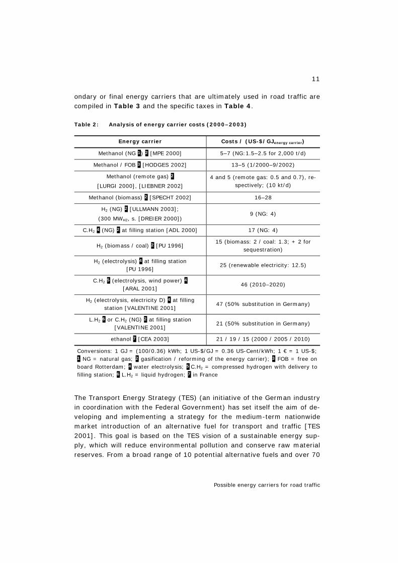
The specific costs (per energy content of the energy carrier) for the provi-sion of different primary and secondary or final energy carriers that are ul-timately used in road traffic are compiled in Table 2.
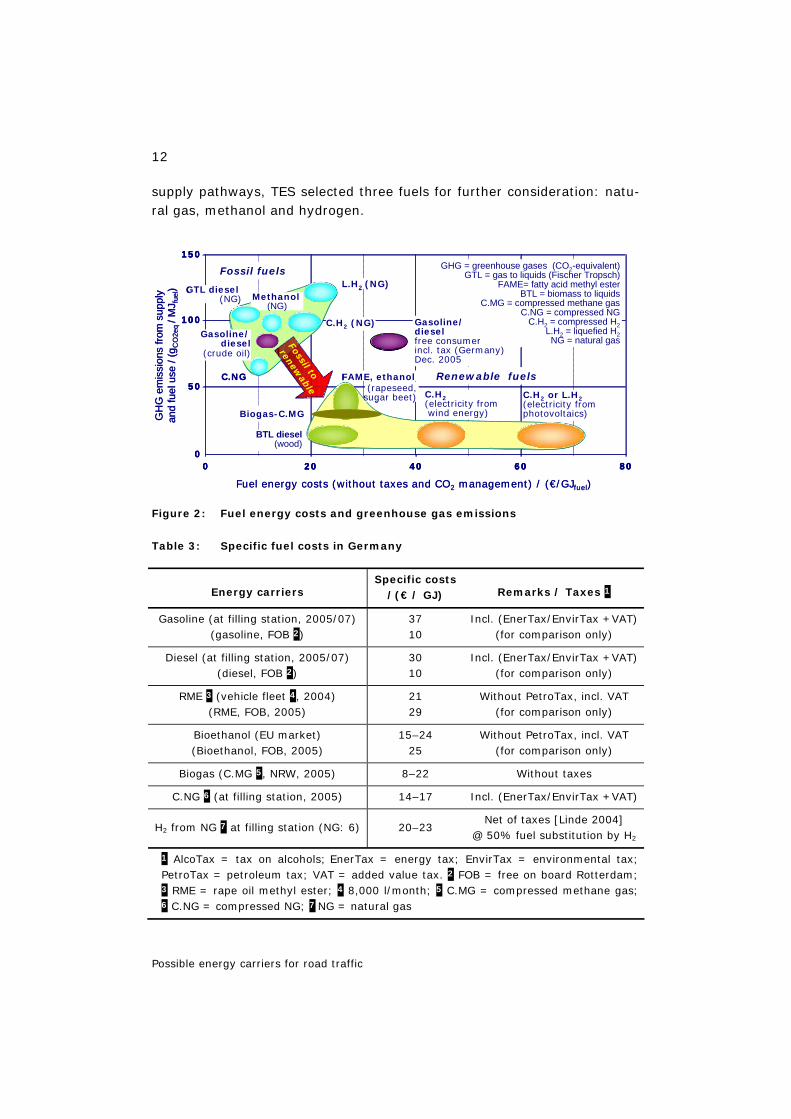
Figure 2 shows the dependency between specific greenhouse gas emis-sions and specific fuel costs. The specific costs (per energy content of the energy carrier) in Germany for the provision of different primary and sec-
11
Possible energy carriers for road traffic
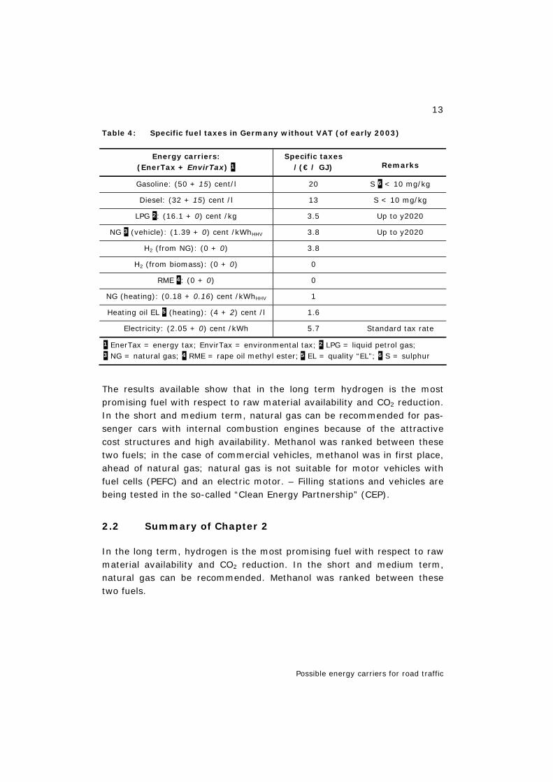
ondary or final energy carriers that are ultimately used in road traffic are compiled in Table 3 and the specific taxes in Table 4.
Table 2: Analysis of energy carrier costs (2000–2003)
Energy carrier Costs / (US-$/GJenergy carrier)
Methanol (NG 1) 2 [MPE 2000] 5–7 (NG:1.5–2.5 for 2,000 t/d)
Methanol / FOB 3 [HODGES 2002] 13–5 (1/2000–9/2002)
Methanol (remote gas) 2
[LURGI 2000], [LIEBNER 2002]
4 and 5 (remote gas: 0.5 and 0.7), re-spectively; (10 kt/d)
Methanol (biomass) 2 [SPECHT 2002] 16–28
H2 (NG) 2 [ULLMANN 2003];
(300 MWH2, s. [DREIER 2000]) 9 (NG: 4)
C.H2 4 (NG) 2 at filling station [ADL 2000] 17 (NG: 4)
H2 (biomass / coal) 2 [PU 1996] 15 (biomass: 2 / coal: 1.3; + 2 for
sequestration)
H2 (electrolysis) 4 at filling station [PU 1996]
25 (renewable electricity: 12.5)
C.H2 5 (electrolysis, wind power) 4 [ARAL 2001]
46 (2010–2020)
H2 (electrolysis, electricity D) 4 at filling station [VALENTINE 2001]
47 (50% substitution in Germany)
L.H2 6 or C.H2 (NG) 2 at filling station [VALENTINE 2001]
21 (50% substitution in Germany)
ethanol 7 [CEA 2003] 21 / 19 / 15 (2000 / 2005 / 2010)
Conversions: 1 GJ = (100/0.36) kWh; 1 US-$/GJ = 0.36 US-Cent/kWh; 1 € = 1 US-$; 1 NG = natural gas; 2 gasification / reforming of the energy carrier); 3 FOB = free on board Rotterdam; 4 water electrolysis; 5 C.H2 = compressed hydrogen with delivery to filling station; 6 L.H2 = liquid hydrogen; 7 in France
The Transport Energy Strategy (TES) (an initiative of the German industry in coordination with the Federal Government) has set itself the aim of de-veloping and implementing a strategy for the medium-term nationwide market introduction of an alternative fuel for transport and traffic [TES 2001]. This goal is based on the TES vision of a sustainable energy sup-ply, which will reduce environmental pollution and conserve raw material reserves. From a broad range of 10 potential alternative fuels and over 70
12
Possible energy carriers for road traffic
supply pathways, TES selected three fuels for further consideration: natu-ral gas, methanol and hydrogen.
Figure 2: Fuel energy costs and greenhouse gas emissions
Table 3: Specific fuel costs in Germany
Energy carriers Specific costs
/(€ / GJ) Remarks / Taxes 1
Gasoline (at filling station, 2005/07) (gasoline, FOB 2)
37 10
Incl. (EnerTax/EnvirTax +VAT) (for comparison only)
Diesel (at filling station, 2005/07) (diesel, FOB 2)
30 10
Incl. (EnerTax/EnvirTax +VAT) (for comparison only)
RME 3 (vehicle fleet 4, 2004) (RME, FOB, 2005)
21 29
Without PetroTax, incl. VAT (for comparison only)
Bioethanol (EU market) (Bioethanol, FOB, 2005)
15–24 25
Without PetroTax, incl. VAT (for comparison only)
Biogas (C.MG 5, NRW, 2005) 8–22 Without taxes
C.NG 6 (at filling station, 2005) 14–17 Incl. (EnerTax/EnvirTax +VAT)
H2 from NG 7 at filling station (NG: 6) 20–23 Net of taxes [Linde 2004]
@ 50% fuel substitution by H2
1 AlcoTax = tax on alcohols; EnerTax = energy tax; EnvirTax = environmental tax; PetroTax = petroleum tax; VAT = added value tax. 2 FOB = free on board Rotterdam; 3 RME = rape oil methyl ester; 4 8,000 l/month; 5 C.MG = compressed methane gas; 6 C.NG = compressed NG; 7 NG = natural gas
Fuel energy costs (without taxes and CO2 management) / (€/GJfuel)
GH
G e
mis
sion
sfro
msu
pply
and
fuel
use
/ (g C
O2e
q / M
J fue
l)
150
100
50
00 20 40 60 80
C.NG
C.H2 (NG)
Methanol (NG)
C.H2(electricity fromwind energy)
C.H2 or L.H2(electricity fromphotovoltaics)
FAME, ethanol
L.H2 (NG)
Gasoline/ diesel
(crude oil)
BTL diesel(wood)
Fossil to
renewable
GTL diesel(NG)
Biogas-C.MG
(rapeseed,sugar beet)
Renewable fuels
Fossil fuels GHG = greenhouse gases (CO2-equivalent) GTL = gas to liquids (Fischer Tropsch)
FAME= fatty acid methyl esterBTL = biomass to liquids
C.MG = compressed methane gasC.NG = compressed NG
C.H2 = compressed H2L.H2 = liquefied H2
NG = natural gas
Gasoline/dieselfree consumerincl. tax (Germany)Dec. 2005
Fuel energy costs (without taxes and CO2 management) / (€/GJfuel)
GH
G e
mis
sion
sfro
msu
pply
and
fuel
use
/ (g C
O2e
q / M
J fue
l)
150
100
50
00 20 40 60 80
150
100
50
00 20 40 60 80
C.NG
C.H2 (NG)
Methanol (NG)
C.H2(electricity fromwind energy)
C.H2 or L.H2(electricity fromphotovoltaics)
FAME, ethanol
L.H2 (NG)
Gasoline/ diesel
(crude oil)
BTL diesel(wood)
Fossil to
renewable
GTL diesel(NG)
Biogas-C.MG
(rapeseed,sugar beet)
Renewable fuels
Fossil fuels GHG = greenhouse gases (CO2-equivalent) GTL = gas to liquids (Fischer Tropsch)
FAME= fatty acid methyl esterBTL = biomass to liquids
C.MG = compressed methane gasC.NG = compressed NG
C.H2 = compressed H2L.H2 = liquefied H2
NG = natural gas
Gasoline/dieselfree consumerincl. tax (Germany)Dec. 2005
13
Possible energy carriers for road traffic
Table 4: Specific fuel taxes in Germany without VAT (of early 2003)
Energy carriers: (EnerTax + EnvirTax) 1
Specific taxes /(€ / GJ) Remarks
Gasoline: (50 + 15) cent/l 20 S 6 < 10 mg/kg
Diesel: (32 + 15) cent /l 13 S < 10 mg/kg
LPG 2: (16.1 + 0) cent /kg 3.5 Up to y2020
NG 3 (vehicle): (1.39 + 0) cent /kWhHHV 3.8 Up to y2020
H2 (from NG): (0 + 0) 3.8
H2 (from biomass): (0 + 0) 0
RME 4: (0 + 0) 0
NG (heating): (0.18 + 0.16) cent /kWhHHV 1
Heating oil EL 5 (heating): (4 + 2) cent /l 1.6
Electricity: (2.05 + 0) cent /kWh 5.7 Standard tax rate
1 EnerTax = energy tax; EnvirTax = environmental tax; 2 LPG = liquid petrol gas; 3 NG = natural gas; 4 RME = rape oil methyl ester; 5 EL = quality “EL”; 6 S = sulphur
The results available show that in the long term hydrogen is the most promising fuel with respect to raw material availability and CO2 reduction. In the short and medium term, natural gas can be recommended for pas-senger cars with internal combustion engines because of the attractive cost structures and high availability. Methanol was ranked between these two fuels; in the case of commercial vehicles, methanol was in first place, ahead of natural gas; natural gas is not suitable for motor vehicles with fuel cells (PEFC) and an electric motor. – Filling stations and vehicles are being tested in the so-called “Clean Energy Partnership” (CEP).
2.2 Summary of Chapter 2
In the long term, hydrogen is the most promising fuel with respect to raw material availability and CO2 reduction. In the short and medium term, natural gas can be recommended. Methanol was ranked between these two fuels.
14
Methanol and alternative fuels for road traffic
3 Methanol and alternative fuels for road traffic
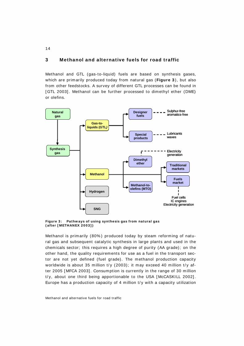
Methanol and GTL (gas-to-liquid) fuels are based on synthesis gases, which are primarily produced today from natural gas (Figure 3), but also from other feedstocks. A survey of different GTL processes can be found in [GTL 2003]. Methanol can be further processed to dimethyl ether (DME) or olefins.
Figure 3: Pathways of using synthesis gas from natural gas (after [METHANEX 2003])
Methanol is primarily (80%) produced today by steam reforming of natu-ral gas and subsequent catalytic synthesis in large plants and used in the chemicals sector; this requires a high degree of purity (AA grade); on the other hand, the quality requirements for use as a fuel in the transport sec-tor are not yet defined (fuel grade). The methanol production capacity worldwide is about 35 million t/y (2003); it may exceed 40 million t/y af-ter 2005 [MFCA 2003]. Consumption is currently in the range of 30 million t/y, about one third being apportionable to the USA [McCASKILL 2002]. Europe has a production capacity of 4 million t/y with a capacity utilization
Synthesisgas
Methanol
Gas-to-liquids (GTL)
Specialproducts
Dimethylether
Designerfuels
Fuelsmarket
Traditionalmarkets
Electricitygeneration
Fuel cellsIC engines
Electricity generation
Lubricantswaxes
Sulphur-freearomatics-free
Methanol-to-olefins (MTO)
Naturalgas
SNG
Hydrogen
Synthesisgas
Methanol
Gas-to-liquids (GTL)
Specialproducts
Dimethylether
Designerfuels
Fuelsmarket
Traditionalmarkets
Electricitygeneration
Fuel cellsIC engines
Electricity generation
Lubricantswaxes
Sulphur-freearomatics-free
Methanol-to-olefins (MTO)
Naturalgas
SNG
Hydrogen
15
Methanol and alternative fuels for road traffic
of 3 million t/y in 1999 [VRIENS 2000]. The use of methanol is largely fo-cused on the chemicals market today (about one third for formaldehyde worldwide – in Europe about 50% of the methanol market; also for acetic acid, methanol derivatives and solvents) [McCASKILL 2000], [McCASKILL 2002].
Methanol has been used as a fuel for:
– internal combustion engines, in California/USA: M85 (passenger car) with filling stations (without significance today),
– the M100 programme (M85) in Germany 15–20 years ago; 100 cars and a few filling stations, inter alia at UK Wesseling/DEA (without sig-nificance today),
– the M100 DI (direct-injection) engines in the USA and Germany (diesel concept with ignition aid), at FEV/Aachen, Volkswagen and EPA/USA (without significance today),
– fuel cell power trains with low-temperature fuel cells (without signifi-cance today).
Apart from its direct use as a fuel for vehicles, methanol is also being used as feedstock for the production of methyl tert-buthyl ether (MTBE). As a blend component for gasoline MTBE works as an octane booster with si-multaneous oxygen enrichment (cf. Chapter 11.2).
Methanol (CH3OH) is also used for the production of dimethyl ether (DME, C2H6O). DME can be used as a diesel substitute fuel in diesel combustion engines without particulate emissions. DME is produced from methanol splitting off water and it is gaseous at ambient temperature and pressure and is stored and transported in the liquid state at low pressures (DME: LHV=28 MJ/kg; methanol: LHV=20 MJ/kg).
2 CH3OH = C2H6O + H2O
Molar mass / (kg/kmol) 2 x 32 = 46 + 18
Molar mass / (%) 100 = 72 + 28
Methanol is also used for the transesterification of vegetable oil. The physical properties of the oil can be modified by changing the molecular structure of the fatty acid molecules. This chemical process – so-called transesterification – is used to fulfil the engine-specific requirements of a fuel. Transesterification or alcoholysis is understood to be the exchange of an alcohol (e.g. trivalent alcohol, glycerol) bound in ester (here vegetable oil) for another one (e.g. monovalent alcohol, methanol). Feedstocks are rape oil and methanol (about 5% relative to RME in terms of energy). The
16
Methanol and alternative fuels for road traffic
end products are rape oil methyl ester (RME) (RME: LHV=37 MJ/kg; diesel fuel: LHV=43 MJ/kg) and glycerol.
Associated gas according to [LIEBNER 2002] is available in large quanti-ties worldwide with about 1011 m3/a (corresponding to 130 million t/y of methanol in terms of energy) at low cost [HOLMES 2000], [HOLTMANN 2001]. At a cost level of ≤ 1 $/GJassociated gas, methanol production plants with capacities of 5,000 t/d of methanol (so-called megaplants) can be constructed. This would possibly lead to a declining utilization of already existing global production capacities, even by dual use of reserves 3, but would above all significantly influence the production costs for methanol. Single-stranded megaplants according to the process of combined reform-ing with multi-stage methanol synthesis [STREB GÖHNA 2000] are being constructed inter alia in Trinidad and Bandar Assaluyeh/Iran according to the LURGI process [LURGI 2000] and [JONES 2000] (cf. Chapter 7). Smaller plants – as in Germany – often have the advantage of short deliv-ery channels to the consumer, but the proceeds for the methanol pro-duced will be lower due to the higher generating costs.
In the case of large gas volumes available far away from the consumers (remote gas, stranded gas), a suitable strategy for their use has to be found. According to [HOLTMANN 2001], the transport of electric current (which is produced in situ “at the well” with the aid of natural gas) via long-distance lines or the transport of natural gas in pipelines is only eco-nomically efficient up to distances of 2,500 km. In contrast, the in-situ production of LNG (liquefied natural gas), DME (dimethyl ether), hydro-gen, methanol or a combined production of methanol and propylene or methanol and ammonia would represent an alternative solution for use. Before realizing such options, however, it is necessary – as a function of natural gas qualities (content of sulphur, carbon dioxide, nitrogen and higher hydrocarbons) – to analyse the markets and the total primary en-ergy input while minimizing CO2 emissions.
3 Associated gas has so far usually been vented or flared. This gas could be used to pro-duce and utilize methanol. The corresponding amount of fossil-based fuel in terms of en-ergy would then be saved and the associated CO2 emissions avoided. Dual use of re-serves would then mean: using the associated gas and saving fossil-based fuel.
17
Methanol and alternative fuels for road traffic
3.1 Methanol for MTBE production
A considerable proportion of methanol is used for the production of MTBE. In Europe and the USA, MTBE is hitherto used as gasoline blend in the transport sector; it serves as an octane booster and a “clean” oxygen-enriching component in carburettor fuel. The aim is also a reduction of CO emissions according to the environmental regulations in the USA, the EU and other countries. Unlike Europe, however, the USA is clearly changing its attitude to the use of MTBE.
MTBE (C5H12O) is produced from methanol and isobutene (C4H8). The mass-related lower heating value of MTBE (LHV=35 MJ/kg) is almost twice as high as that of methanol (LHV=20 MJ/kg) (Table 38).
CH3OH+C4H8 = C5H12O
Molar mass / (kg/kmol) 32 + 56 = 88
Molar mass / (%) 36,4 +63,6 = 100
Isobutene is produced during naphtha steam reforming, from cracked gases of the oil industry, and during the catalytic dehydrogenation of bu-tane or isobutane. In recent years, the extensive use of MTBE has gov-erned the demand for methanol worldwide. In view of the hazards to drinking water due to leakages from gasoline tanks in California [FISLER 2000], a discussion has developed in the USA on the permissibility of the use of MTBE as a lead substitute and an oxygen-donating fuel component (a detailed survey of the environmental behaviour (Henry coefficient) and the microbial degradation and dangers to health of MTBE is given in [LIN-NEMANN 2003]). The ban on the use of MTBE in California has become ef-fective by the end of 2003 (cf. Chapter 11.2). If the second largest sales market for methanol were to shrink for this reason, considerable surplus amounts of methanol could exert pressure on the market.
3.2 M85 for direct-injection combustion engines
As long ago as the early eighties, engines were developed that could run on methanol-gasoline fuel mixtures. These fuels initially only contained 15% methanol (M15), but the methanol fraction was later gradually in-creased. Additional solubilizers are required under certain conditions and depending on the water content of the methanol. Up to a methanol frac-tion of approx. 3% no modifications to the vehicle (engine and peripher-
18
Methanol and alternative fuels for road traffic
als) are needed. Admixing 3%-15% methanol requires an adaptation of the materials of the fuel system (plastics) that directly come into contact with methanol.
Pure methanol was originally not suitable for use in vehicles, since its low vapour pressure led to cold-start problems. For this reason, 10–15vol% of a gasoline fraction was added to the methanol. In order to optimally utilize the fuel properties of M85, modifications to the existing engine concepts were necessary.
Initial experience with M85/M90 was made with modified gasoline en-gines, in which the high octane numbers enabled an increase of the com-pression ratio compared to gasoline operation. Due to the wide ignition range of methanol it was additionally possible to realize lean operation. As early as 1982 it was possible to achieve more favourable consumption values for methanol vehicles in the ECE cycle than for comparable gaso-line vehicles. Due to the lean operation, low flame temperature and high evaporation heat of methanol fuels, the methanol vehicles also displayed extremely low nitrogen oxide emission values. In the following years, the engine concept was further improved by adapting the combustion cham-ber configuration and the carburetion system to the increased compres-sion values.
Optimized concepts for M85 were tested worldwide and developed almost up to the production stage. Due to the lack of a large-area supply infra-structure, development has been increasingly focused on more universal flexible fuel vehicles (FFV), which can run on M85, gasoline and arbitrary fuel mixtures. This ensures full user mobility. VOLKSWAGEN developed the multi-fuel-concept vehicle (MFC/MFV) in the late eighties and from 1990 took part in a major test programme with about 100 vehicles in Cali-fornia [WEGENER 1999].
The rising demands made on the quality of exhaust emissions led to the development of an engine concept for operation with pure methanol (M100). In 1990, the companies FEV/Aachen, Volkswagen and EPA/USA presented a concept for a methanol engine with direct injection (DI) based on a standard 1.9 l DI diesel engine of Volkswagen. Test operation showed very low NOx and particulate emissions in comparison to the diesel en-gine. The emissions of non-methane organic gases (NMOGs) were clearly higher than from comparable diesel engines. The NMOGs largely consisted of unburned methanol (with low ozone forming potential) from the cold-start phase (whereas unburned hydrocarbons from the cold-start phase of gasoline/diesel engines have a high ozone forming potential). In contrast
19
Methanol and alternative fuels for road traffic
to the gasoline engine, the DI methanol engine displayed very low alde-hyde emissions.
This engine concept combines the advantage of the high efficiency of di-rect-injection, high-compression engines with that of the particulate-free combustion of alcohols. Due to the low cetane number of alcohol fuels, a spark ignition system or an additional injection of diesel fuel is required. The glow ignition system leads to satisfactory cold-start and cold-shutdown behaviour. A great problem, however, is the increased suscepti-bility to corrosion and wear due to the poor lubricating effect of methanol [WEGENER 1999], [HILGER et al. 1990].
In California and some cities in the USA, flexible fuel vehicles with internal combustion engines running on gasoline or methanol/fuel mixtures were in operation. The vehicles were only equipped with one tank, but had a fuel sensor. Approx. 15,000 passenger cars of about 20,000 were run in California. This project involved the companies Ford, GM, Chrysler, VW, Nissan, Toyota and Mercedes. With the participation of ARCO, Chevron, Exxon, Mobil, Shell, Texaco and Ultramar, 330 methanol transit buses with Detroit diesel 6V92 engines were in operation in California, whereas less than 100 filling stations were available for refuelling with M85. Certi-fied vehicles are no longer on the market today; the 10-year programme with M85 was terminated, the last filling stations are being closed down or modified. Within the framework of the California Fuel Cell Partnership, there has been a methanol filling station of Methanex in Sacramento/CA since 25.4.2002. Methanol does not play a role in the Californian near-term clean fuel infrastructure and vehicles planning [LYNN 2001], [WARD 2002], [CEC 2001], [MI 2003].
3.3 Methanol for fuel cells with reformers
Novel power trains for traffic will only be able to attain a great application potential if they contribute towards conserving existing energy resources and reducing pollutant emissions due to higher system efficiency than in-ternal combustion engine drives. However, they must also be comparable to conventional vehicles with respect to performance, usefulness (useful interior and payload) and range. And ultimately the costs must be com-petitive.
To this end, the overall efficiency and total emissions of full fuel cycles (energy balance from primary energy carrier up to the vehicle in opera-tion, cf. Table 5) must be improved in comparison to conventional drives
20
Methanol and alternative fuels for road traffic
for traffic. Reductions in weight, recovery of braking energy or traffic guidance systems can provide further contributions. The use of low-carbon primary energy carriers in drive systems with optimum energy manage-ment also contributes to emissions reduction. Internal combustion engine drives based on the fossil primary energy carrier oil are dominant today.
Electric drives with batteries as the power source currently only represent a niche market. The infrastructure of mobile energy supply is also charac-terized by internal combustion engine drives. Modern industrial nations have filling stations all over the country.
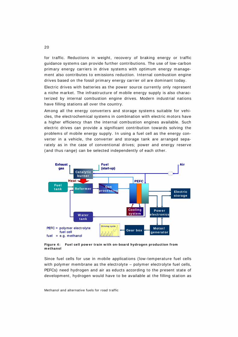
Among all the energy converters and storage systems suitable for vehi-cles, the electrochemical systems in combination with electric motors have a higher efficiency than the internal combustion engines available. Such electric drives can provide a significant contribution towards solving the problems of mobile energy supply. In using a fuel cell as the energy con-verter in a vehicle, the converter and storage tank are arranged sepa-rately as in the case of conventional drives; power and energy reserve (and thus range) can be selected independently of each other.
Figure 4: Fuel cell power train with on-board hydrogen production from methanol
Since fuel cells for use in mobile applications (low-temperature fuel cells with polymer membrane as the electrolyte – polymer electrolyte fuel cells, PEFCs) need hydrogen and air as educts according to the present state of development, hydrogen would have to be available at the filling station as
Fueltank
Catalyticburner
Reformer
Coolingsystem
AirFuel(start-up)
Exhaustgas
Watertank
PEFCHeat
Gasprocessing Electric
storage
Gear boxMotor/
generator
Powerelectronics
PEFC = polymer electrolytefuel cell
fuel = e.g. methanol
Driving cycle
Fueltank
Catalyticburner
Reformer
Coolingsystem
AirFuel(start-up)
Exhaustgas
Watertank
PEFCHeat
Gasprocessing Electric
storage
Gear boxMotor/
generator
Powerelectronics
PEFC = polymer electrolytefuel cell
fuel = e.g. methanol
Driving cycle
21
Methanol and alternative fuels for road traffic
the energy carrier for direct use (hydrogen variant) and methanol or liquid hydrocarbons (such as gasoline or diesel) for indirect use. The indirect use of reformed methanol (Figure 4) or liquid hydrocarbon (both with on-board production of hydrogen) reduces the efficiency of the fuel cell power train in comparison to direct use. There is at present no infrastructure for refuelling methanol-operated fuel cell vehicles.
In a drive system for mobile application with methanol tank and reformer, fuel cell, energy storage and electric motor (Figure 4), a liquid metha-nol/water mixture is used as the fuel, which under ambient conditions ex-hibits physical properties similar to those of conventional fuels. Water does not have to be additionally filled in but is obtained as the oxidation product of hydrogen, condensed out of the off-gas mixture of the fuel cell and passed into the tank. The methanol/water mixture is delivered by a fuel pump into an evaporator, where it is heated, evaporated and super-heated. The superheated methanol/water mixture is then converted into a hydrogen-rich synthesis gas in a reformer. Heat for the heterogeneously catalysed reaction is supplied by a low-emission catalytic burner, in which the residual gases are converted into energy.
If in today's large-area traffic the fuel cell power train of a passenger car were to be operated with hydrogen and air from a filling station (hydro-gen/air variant), this would pose considerable problems: the storage den-sity of present-day hydrogen storage tanks is too low (leading to weight and volume problems) and an infrastructure for hydrogen supply does not exist for these cars. The costs before tax for hydrogen based on natural gas would be 2–3 times higher than for gasoline or diesel fuel even in the case of a high substitution rate of about 50%. However, the evaluation of these elevated costs is relativized by the fact that – in comparison to gasoline-fuelled vehicles with internal combustion engines – the hydro-gen-fuelled vehicle has an about 40% lower energy demand (cf. Table 3, Table 4). Figure 2 shows today's specific energy carrier costs (before taxes) for fuel supply in Germany as a function of the specific CO2 emis-sions which arise in delivering the respective fuel up to the filling station and using 1 MJ of the respective energy carrier.
In the medium term, a simpler solution approach could be to tank up cars with liquid energy carriers such as methanol and gasoline/diesel and pro-duce a hydrogen-rich synthesis gas from these on board the vehicle. Prob-lems such as range and infrastructure can thus be solved more easily than for the hydrogen variant, but on-board hydrogen production impairs the dynamics of the power train and requires the installation of an additional
22
Methanol and alternative fuels for road traffic
short-term storage system for acceleration phases. The use of methanol or gasoline/diesel gives rise to the question of whether the fuel cell should be modified with the aim of oxidizing hydrogen-rich synthesis gases also containing CO, CO2 and water in the fuel cell using atmospheric oxygen. Finally, the higher system complexity requires extra costs.
In research and development, at present, the methanol and gaso-line/diesel variants are only being dealt with to a limited extent as transi-tion solutions on the road to the use of pure hydrogen. In the medium to long term, the development of the fuel cell for direct methanol use, the di-rect methanol fuel cell, DMFC, is also being pursued [JÖRISSEN 2000]; in the long term, providing a low-cost infrastructure, if possible, based on hydrogen produced from renewable sources, the use of the above-mentioned hydrogen variant is envisaged, which is currently implemented in most of the fuel cell concept cars.
In contrast to mobile applications, the DMFC has a high potential for use in portable applications for electric power generators with fuel cells [HFC 2003] (cf. Chapter 11.1) or as power sources for small traction applica-tions in industry such as floor conveyors. Relevant studies are being con-ducted worldwide, inter alia at Research Centre Jülich [DOHLE 2003].
The development of fuel-cell-powered vehicles into products for a possible mass market is influenced by many factors. A comparison of the balances of the energy and emission chains for fuel supply and passenger car op-eration (well-to-wheels analysis) in Germany shows according to [KRAKE 2005] in part advantages of the cars with fuel cells over those with other drive systems (Table 5). This includes advantages concerning:
– primary energy requirements (about 25% lower for future C.H2-FC pas-senger cars compared to gasoline-ICE cars, but no bonus for CH3OH-FC cars with CH3OH production from natural gas in Germany),
– CO2 emissions (about 38% lower for future C.H2-FC passenger cars, about 13% lower for methanol-FC cars with methanol production from natural gas at the well, both in comparison to gasoline-ICE cars) and
– regulated emissions (H2-FC cars are zero-emission vehicles; methanol-FC cars are clearly below the EURO-4 standard and fulfil the stricter standards of Californian ZEV legislation.
Moreover, fuel cell vehicles must be comparable to modern vehicles with gasoline/diesel drives concerning performance and driving comfort, pay-load, range and cost. Additional advantages and new value-adding poten-tials must be perceivable for fuel cell vehicles.

23
Methanol and alternative fuels for road traffic
A balance comparison of the full fuel cycles is only possible to a limited extent due to the different development level of fuel cell power trains. Thus, the development of fuel cell power trains with on-board reforming of conventional diesel from crude oil or Fischer-Tropsch diesel from natural gas (FT-d) and direct methanol supply to the fuel cell (DMFC) is much less advanced than that of indirect methanol use (on-board reforming) or di-rect hydrogen use (PEFC). A future gasoline drive was chosen here as the basis for comparison (column 2 in Table 5).
In comparison to German or European studies on gasoline-fuelled refer-ence vehicles of today, American balances (such as [MFCA 2003] for fuel cell vehicles display greater reductions in primary energy requirements and CO2 emissions than should result for a balance based on a future ref-erence vehicle. This is due to the fact that the reference vehicle in the American balances is a gasoline-fuelled passenger car of today with a drive efficiency of 13–17%, which depending on the vehicle corresponds to a fuel consumption of about 7–8 l gasoline/100 km. A car drive of the future, however, according to [GRUBE et al. 2001] will be able to reach a drive efficiency of about 22% and will consume about 5 l gasoline/100 km (for this estimate, the weight and the vehicle parameters of the above reference vehicle and driving through the European driving cycle were as-sumed; cf. Figure 4). This reduces the reductions in primary energy de-mand and CO2 emissions.
The results of a comparison of different fuel/vehicle systems with respect to primary energy input and climate-relevant emissions are shown in Table 5 [KRAKE 2005]. The reference vehicle chosen was a gasoline car, which relative to diesel cars exhibits a higher energy demand in the driv-ing cycle, but has lower exhaust gas emissions from the present perspec-tive (no particulate emissions). For the associated fuel supply, primary energy expenditure on exploration/extraction at the well, long-distance transport as well as refining (regional refineries in Germany) and distribu-tion by truck have been included. Other full fuel cycles have very different supply structures depending on their origin and on the physical properties of the primary and secondary energy carriers as well as on the choice of the site for fuel production (remote, regional and local). In the literature, in part very different boundary conditions are assumed, which only allow a limited comparability of the results.

24
Methanol and alternative fuels for road traffic
Table 5: Energy, efficiency and CO2 balances of full fuel cycles for compact passenger cars [KRAKE 2005]
PES FES FES plant
Crd.oil gasoline
reg
Crd.oil diesel
reg
NG FT-d rem
NG C.NG local
NG C.H2
rem/reg
EL C.H2
local
NG CH3OH
rem
NG CH3OH
rem
NG L.H2
rem
EC / engine
ICE ICE ICE ICE FC EM
FC EM
ref+ FC EM
DMFC EM
FC EM
mcar [kg] 1,064 1,062 1,062 1,064 1,164 1,164 1,257 1,161 1,076
ηFSC [%] 81 85 61 81 64/63 25 64 64 51
Ecar [MJ/100km]
153 132 132 145 91 91 125 111 87
ηcar [%] 22 25 25 23 39 39 30 31 39
EFFC [MJ/100km]
190 155 215 180 142/145 362 195 173 170
ηFFC [%] 18 21 16 19 25/25 10 19 20 20
CO2, FFC [kg/100km]
13.7 11.3 14.3 10.6 8.4/8.5 21.2 11.9 10.6 9.7
Row 1: ES = energy source; PES = primary ES; FES = final ES; FES plant = plant for the conversion of PES into FES (sites: loc=local, reg=regional, rem=remote); Crd.oil = crude oil; NG = natural gas; EL = electricity mix Germany (for water electrolysis); FT-d = Fischer-Tropsch diesel; C.NG = compressed NG; C.H2 = compressed H2; CH3OH = methanol; L.H2 = liquefied H2. – Row 2: EC = energy converter; ICE = internal combus-tion engine; FC = fuel cell (PEFC); ref+FC = reformer with FC; DMFC = direct methanol FC; EM = electric motor. – Row 3: car = passenger car. – Row 4: FSC = fuel supply chain (PES up to FES). – Row 5: E = energy demand. – Row 6: η = efficiency. – Row 7: FFC = full fuel cycle (PES up to wheels) .
In order to enable a better evaluation of the balancing presented here, mean values from the comparison of international studies were used for the criteria “primary energy input” and “climate-relevant emissions”, as can also be seen in Table 5 [KRAKE 2005] (FFC). For calculating the inte-gral well-to-wheels value (MJPE/km), the mean value of the study data on well-to-tank fuel supply (MJPE/MJfuel) was multiplied by the tank-to-wheel value for the vehicles (MJfuel/km). The potentials for improvement com-pared to the reference scenario, which can be derived from these mean values, are shown in Figure 5.
It can be seen that except for the use of Fischer-Tropsch diesel (based on natural gas) in fuel cell power trains all the fuel/vehicle systems investi-gated display advantages over the reference system concerning the bal-ance of greenhouse gases.
A comparison of internal-combustion-engine-based vehicles including the hybrid variant with the fuel cell vehicles shows that under the chosen
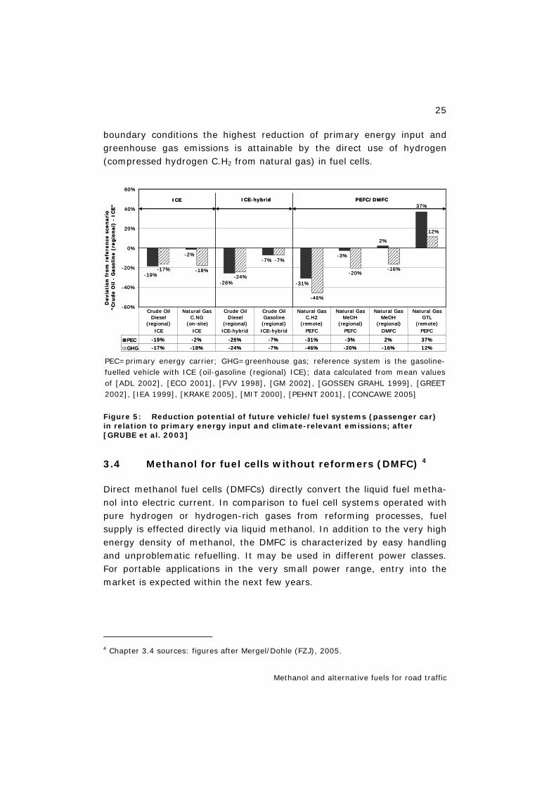
25
Methanol and alternative fuels for road traffic
boundary conditions the highest reduction of primary energy input and greenhouse gas emissions is attainable by the direct use of hydrogen (compressed hydrogen C.H2 from natural gas) in fuel cells.
PEC=primary energy carrier; GHG=greenhouse gas; reference system is the gasoline-fuelled vehicle with ICE (oil-gasoline (regional) ICE); data calculated from mean values of [ADL 2002], [ECO 2001], [FVV 1998], [GM 2002], [GOSSEN GRAHL 1999], [GREET 2002], [IEA 1999], [KRAKE 2005], [MIT 2000], [PEHNT 2001], [CONCAWE 2005]
Figure 5: Reduction potential of future vehicle/fuel systems (passenger car) in relation to primary energy input and climate-relevant emissions; after [GRUBE et al. 2003]
3.4 Methanol for fuel cells without reformers (DMFC) 4
Direct methanol fuel cells (DMFCs) directly convert the liquid fuel metha-nol into electric current. In comparison to fuel cell systems operated with pure hydrogen or hydrogen-rich gases from reforming processes, fuel supply is effected directly via liquid methanol. In addition to the very high energy density of methanol, the DMFC is characterized by easy handling and unproblematic refuelling. It may be used in different power classes. For portable applications in the very small power range, entry into the market is expected within the next few years.
4 Chapter 3.4 sources: figures after Mergel/Dohle (FZJ), 2005.
-2%-7%
-31%
-3%
2%
-17% -18%-24%
-7%
-46%
-20%-16%
12%
-19%
-26%
37%
-60%
-40%
-20%
0%
20%
40%
60%
Devia
tio
n f
rom
refe
ren
cesc
en
ari
o"C
rud
eO
il -
Gaso
lin
e(r
eg
ion
al)
-IC
E"
PEC -19% -2% -26% -7% -31% -3% 2% 37%
GHG -17% -18% -24% -7% -46% -20% -16% 12%
Crude OilDiesel
(regional)
Natural GasC.NG
(on-site)
Crude OilDiesel
(regional)
Crude OilGasoline
(regional)
Natural GasC.H2
(remote)
Natural GasMeOH
(regional)
Natural GasMeOH
(regional)
Natural GasGTL
(remote)
ICE PEFC/DMFCICE-hybrid
ICE ICE ICE-hybrid ICE-hybrid PEFC PEFC DMFC PEFC
-2%-7%
-31%
-3%
2%
-17% -18%-24%
-7%
-46%
-20%-16%
12%
-19%
-26%
37%
-60%
-40%
-20%
0%
20%
40%
60%
Devia
tio
n f
rom
refe
ren
cesc
en
ari
o"C
rud
eO
il -
Gaso
lin
e(r
eg
ion
al)
-IC
E"
PEC -19% -2% -26% -7% -31% -3% 2% 37%
GHG -17% -18% -24% -7% -46% -20% -16% 12%
PEC -19% -2% -26% -7% -31% -3% 2% 37%
GHG -17% -18% -24% -7% -46% -20% -16% 12%
Crude OilDiesel
(regional)
Natural GasC.NG
(on-site)
Crude OilDiesel
(regional)
Crude OilGasoline
(regional)
Natural GasC.H2
(remote)
Natural GasMeOH
(regional)
Natural GasMeOH
(regional)
Natural GasGTL
(remote)
ICE PEFC/DMFCICE-hybrid
ICE ICE ICE-hybrid ICE-hybrid PEFC PEFC DMFC PEFC
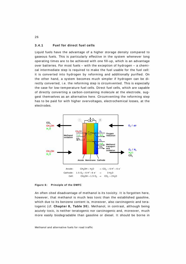
26
Methanol and alternative fuels for road traffic
3.4.1 Fuel for direct fuel cells
Liquid fuels have the advantage of a higher storage density compared to gaseous fuels. This is particularly effective in the system whenever long operating times are to be achieved with one fill-up, which is an advantage over batteries. For most fuels – with the exception of hydrogen – a chemi-cal intermediate step is required to make the fuel usable for the fuel cell: it is converted into hydrogen by reforming and additionally purified. On the other hand, a system becomes much simpler if hydrogen can be di-rectly converted, i.e. the reforming step is circumvented. This is especially the case for low-temperature fuel cells. Direct fuel cells, which are capable of directly converting a carbon-containing molecule at the electrode, sug-gest themselves as an alternative here. Circumventing the reforming step has to be paid for with higher overvoltages, electrochemical losses, at the electrodes.
Figure 6: Principle of the DMFC
An often cited disadvantage of methanol is its toxicity. It is forgotten here, however, that methanol is much less toxic than the established gasoline, which due to its benzene content is, moreover, also carcinogenic and tera-togenic (cf. Chapter 8, Table 30). Methanol, in contrast, although being acutely toxic, is neither teratogenic nor carcinogenic and, moreover, much more easily biodegradable than gasoline or diesel. It should be borne in
CH3OH
Methanol oxidation
O2 / air
O2 / N2
H2OCO2
Oxygenreduction
Methanol transportand oxidation
CO2
Anode Membrane Cathode
Pel
O2
H2O
CH3OH
H2O
CO2
H+solv
H2O
H2O
CH3OHH2O
CO2
O2
H2O
CH3OH
CH3OH
Methanol oxidation
O2 / air
O2 / N2
H2OCO2
Oxygenreduction
Methanol transportand oxidation
CO2
Anode Membrane Cathode
Pel
O2
H2O
CH3OH
H2O
CO2
H+solv
H2O
H2O
CH3OHH2O
CO2
O2
H2O
CH3OH
3 2 2
2 2
3 2 2 2
Anode: CH OH H O CO 6 H 6 e
Cathode: 1.5 O 6 H 6 e 3 H O
Cell: CH OH 1.5 O CO 2H O
+ −
+ −
+ → + +
+ + →
+ → +
27
Methanol and alternative fuels for road traffic
mind when handling methanol that due to its water solubility it can pene-trate through the skin into the body, but this can be prevented by protec-tive measures. Handling methanol is therefore unproblematic in the pro-fessional area where the personnel can be adequately instructed and pro-ceeds with sufficient care. In the hobby and household sector, adequate passive safety measures such as hermetically sealed receptacles permit-ting safe handling would be a precondition for use. In any case, however, it must be stated that methanol is much less dangerous than gasoline which we are used to handle today.
3.4.2 Principle of the DMFC
The central component of the DMFC is the membrane electrode assembly (MEA). The membrane – a proton-conducting plastic foil – separates a methanol/water mixture on the anode side of the fuel cell from the air on the cathode side. In detail, the catalytically activated partial reactions shown in Figure 6 take place.
Inside the cell, the methanol is not pure on the anode side, but for rea-sons of stoichiometry must be present with water in a ratio of at least 1:1. Since the membrane is permeable for methanol, a higher dilution of the methanol is required in real operation. In order to keep the losses due to methanol permeation low, the lowest possible methanol concentration is therefore aimed at on the anode side.
The anode side is normally run in a loop, in which the methanol/water mixture is continuously recycled. The gaseous carbon dioxide produced during the anode reaction is discharged. The recycling configuration also serves to transport the heat losses from the stack and dissipate them to the environment, for example, via a heat exchanger. Methanol is continu-ously fed into the loop to compensate for the methanol consumption.
The electrochemical reactions in a DMFC (Figure 6) proceed much more slowly than in a hydrogen/air fuel cell. The reaction velocity can be influ-enced above all by the design and structure of the MEA.
In order to realize a DMFC system, high-performance electrodes are therefore required, which ensure rapid electrochemical reaction processes [HAMNETT 2003]. The electrodes essentially consist of a conductive graphite fabric, which is in electronically conducting contact with the cata-lyst layer. Binary Pt/Ru catalysts are normally used on the anode and pure Pt on the cathode. Ionically conductive fractions are added to the catalyst
28
Methanol and alternative fuels for road traffic
layers, which are normally introduced as a finely distributed membrane material during electrode fabrication.
The currently most commonly used membrane material is the perfluori-nated sulphonic acid polymer Nafion from DuPont. However, it has some major disadvantages, especially in DMCF operation, so that alternative materials are intensively explored which do not exhibit these disadvan-tages or only to a minor extent.
The proton conductivity of Nafion is only given if the membrane is satu-rated with water. In methanol operation, humidification is always given due to the liquid, aqueous fuel. Since methanol is soluble in water, how-ever, the membrane in addition to water also takes up methanol, which is then passed to the cathode through the membrane. This leads to fuel loss and a degradation in performance due to mixed-potential formation and catalyst poisoning at the cathode.
Thus, for example, the following difficulties are encountered in the practi-cal operation of a direct methanol fuel cell:
- potential losses at the anode due to low catalyst activity,
- losses in efficiency due to fuel losses caused by methanol permeation through the electrolyte membrane,
- potential losses at the cathode due to mixed-potential formation.
3.4.3 Development areas
Market entry for DMFCs is currently seen in the area of portable power supply for laptops, mobile phones, PDAs and for mobile electricity supply up to 5 kW.
In order to introduce such systems onto the market, they must be light-weight and compact. Therefore, high power densities are already needed at moderate operating temperatures between 10 and 50 °C. A basic re-quirement for market entry, apart from some niche applications, is, how-ever, to achieve a cost level that is comparable to existing technologies. Table 6 shows some performance targets for different power classes and application fields of portable fuel cell systems for possible market entry [DOE 2002].
Thus, present-day DMFC systems with about 140 Wh/kg are still two to three times as heavy as comparable lithium/ion batteries. The fuel cell stacks together with pumps, fans and electronic controls as well as the methanol tank require so much space that a module e.g. for a laptop is by far not conceivable.
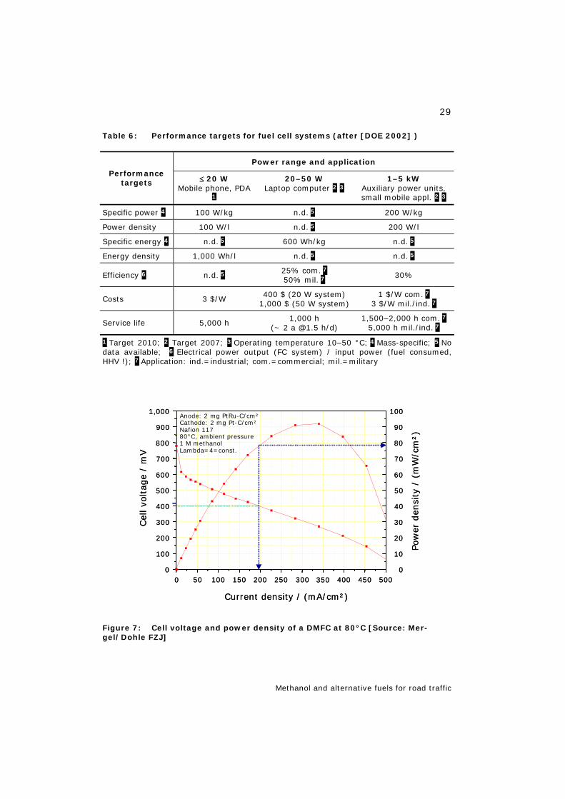
29
Methanol and alternative fuels for road traffic
Table 6: Performance targets for fuel cell systems (after [DOE 2002] )
Power range and application Performance
targets ≤ 20 W Mobile phone, PDA
1
20–50 W Laptop computer 2 3
1–5 kW Auxiliary power units, small mobile appl. 2 3
Specific power 4 100 W/kg n.d. 5 200 W/kg
Power density 100 W/l n.d. 5 200 W/l
Specific energy 4 n.d. 5 600 Wh/kg n.d. 5
Energy density 1,000 Wh/l n.d. 5 n.d. 5
Efficiency 6 n.d. 5 25% com. 7 50% mil. 7
30%
Costs 3 $/W 400 $ (20 W system) 1,000 $ (50 W system)
1 $/W com. 7 3 $/W mil./ind. 7
Service life 5,000 h 1,000 h (~ 2 a @1.5 h/d)
1,500–2,000 h com. 7 5,000 h mil./ind. 7
1 Target 2010; 2 Target 2007; 3 Operating temperature 10–50 °C; 4 Mass-specific; 5 No data available; 6 Electrical power output (FC system) / input power (fuel consumed, HHV !); 7 Application: ind.=industrial; com.=commercial; mil.=military
Figure 7: Cell voltage and power density of a DMFC at 80°C [Source: Mer-gel/Dohle FZJ]
0 50 100 150 200 250 300 350 400 450 5000
100
200
300
400
500
600
700
800
900
1,000
0
10
20
30
40
50
60
70
80
90
100
Cel
lvo
ltage
/ m
V
Current density / (mA/cm²)
Anode: 2 mg PtRu-C/cm²Cathode: 2 mg Pt-C/cm²Nafion 11780°C, ambient pressure1 M methanolLambda=4=const.
Pow
er d
ensi
ty/
(mW
/cm
²)
0 50 100 150 200 250 300 350 400 450 5000
100
200
300
400
500
600
700
800
900
1,000
0
10
20
30
40
50
60
70
80
90
100
Cel
lvo
ltage
/ m
V
Current density / (mA/cm²)
Anode: 2 mg PtRu-C/cm²Cathode: 2 mg Pt-C/cm²Nafion 11780°C, ambient pressure1 M methanolLambda=4=const.
Pow
er d
ensi
ty/
(mW
/cm
²)
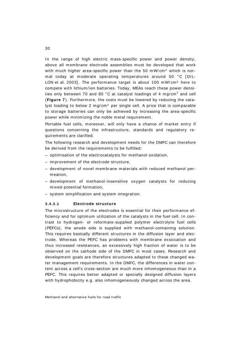
30
Methanol and alternative fuels for road traffic
In the range of high electric mass-specific power and power density, above all membrane electrode assemblies must be developed that work with much higher area-specific power than the 50 mW/cm² which is nor-mal today at moderate operating temperatures around 50 °C [DIL-LON et al. 2003]. The performance target is about 100 mW/cm² here to compete with lithium/ion batteries. Today, MEAs reach these power densi-ties only between 70 and 80 °C at catalyst loadings of 4 mg/cm2 and cell (Figure 7). Furthermore, the costs must be lowered by reducing the cata-lyst loading to below 2 mg/cm² per single cell. A price that is comparable to storage batteries can only be achieved by increasing the area-specific power while minimizing the noble metal requirement.
Portable fuel cells, moreover, will only have a chance of market entry if questions concerning the infrastructure, standards and regulatory re-quirements are clarified.
The following research and development needs for the DMFC can therefore be derived from the requirements to be fulfilled:
– optimisation of the electrocatalysts for methanol oxidation,
– improvement of the electrode structure,
– development of novel membrane materials with reduced methanol per-meation,
– development of methanol-insensitive oxygen catalysts for reducing mixed-potential formation,
– system simplification and system integration.
3.4.3.1 Electrode structure
The microstructure of the electrodes is essential for their performance ef-ficiency and for optimum utilization of the catalysts in the fuel cell. In con-trast to hydrogen- or reformate-supplied polymer electrolyte fuel cells (PEFCs), the anode side is supplied with methanol-containing solution. This requires basically different structures in the diffusion layer and elec-trode. Whereas the PEFC has problems with membrane exsiccation and thus increased resistances, an excessively high fraction of water is to be observed on the cathode side of the DMFC in most cases. Research and development goals are therefore structures adapted to these changed wa-ter management requirements. In the DMFC, the differences in water con-tent across a cell's cross-section are much more inhomogeneous than in a PEFC. This requires better adapted or specially designed diffusion layers with hydrophobicity e.g. also inhomogeneously changed across the area.
31
Methanol and alternative fuels for road traffic
Due to the reactions and the associated possible degradation of the cata-lyst, the active layer of the membrane electrode assembly (MEA) must also be optimized with respect to the given conditions. The German Aero-space Centre (DLR) has developed suitable aids, such as segmented cells, to locally determine the current density distribution in single cells and stacks and to perform local electrochemical impedance spectroscopy [WEISSHAAR et al. 2003]. This makes it possible to measure the influence of different operating parameters on MEA performance during operation and to develop adapted electrodes with inhomogeneous catalyst distribu-tion.
3.4.3.2 New membrane materials
Various membranes are currently under development [GLUE-SEN/STOLTEN 2003]. Membranes on the basis of sulphonated aromatic polymers are currently being developed by several companies and re-search groups. They are regarded as fluorine-free alternatives to Nafion and are expected to be cheaper in mass production than Nafion. These polymers are mostly sulphonated in solution, and the membranes are pro-duced in a casting process. The base polymers for this type of membranes are poly(etherketones), PEK, poly(etheretherketones), PEEK, poly(ethersulphones), poly(sulphones) and poly(imides). These polymers are very stable high-performance materials.
Figure 8: Specific methanol permeability and cell voltage of a sulphonated PEK (sPEK) membrane (80°C, 1 M methanol, 3 bar) [Source: Mergel/Dohle FZJ]
Many studies are based on PEK. The properties of the membranes depend on the quality of the base polymer, on the selectivity of the sulphonation reaction and on the membrane fabrication process. In comparison to Nafion, the sulphonated aromatic polymers take up slightly less water. Whereas Nafion has a few broad conductance channels, in which the sul-
0
1
2
3
0 100 200 300 400 500
Current density / (mA/cm²)
Spec
. per
mea
bili
ty/
(mA/c
m)
Nafion 117sPEK (IEC = 1.4)
0
1
2
3
0 100 200 300 400 500
Current density / (mA/cm²)
Spec
. per
mea
bili
ty/
(mA/c
m)
Nafion 117sPEK (IEC = 1.4)
0
100
200
300
400
500
600
700
0 100 200 300 400 500
Current density / (mA/cm²)
Cel
lvo
ltage
/ m
V
sPEK (40 µm)
Nafion 117 (178 µm)
0
100
200
300
400
500
600
700
0 100 200 300 400 500
Current density / (mA/cm²)
Cel
lvo
ltage
/ m
V
sPEK (40 µm)
Nafion 117 (178 µm)
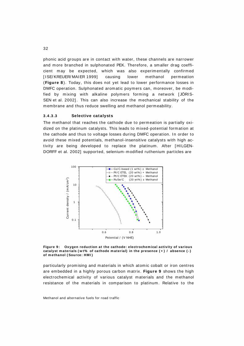
32
Methanol and alternative fuels for road traffic
phonic acid groups are in contact with water, these channels are narrower and more branched in sulphonated PEK. Therefore, a smaller drag coeffi-cient may be expected, which was also experimentally confirmed [ISE/KREUER/MAIER 1999] causing lower methanol permeation (Figure 8). Today, this does not yet lead to lower performance losses in DMFC operation. Sulphonated aromatic poymers can, moreover, be modi-fied by mixing with alkaline polymers forming a network [JÖRIS-SEN et al. 2002]. This can also increase the mechanical stability of the membrane and thus reduce swelling and methanol permeability.
3.4.3.3 Selective catalysts
The methanol that reaches the cathode due to permeation is partially oxi-dized on the platinum catalysts. This leads to mixed-potential formation at the cathode and thus to voltage losses during DMFC operation. In order to avoid these mixed potentials, methanol-insensitive catalysts with high ac-tivity are being developed to replace the platinum. After [HILGEN-DORFF et al. 2002] supported, selenium-modified ruthenium particles are
Figure 9: Oxygen reduction at the cathode: electrochemical activity of various catalyst materials (wt% of cathode material) in the presence (+) / absence (-) of methanol (Source: HMI)
particularly promising and materials in which atomic cobalt or iron centres are embedded in a highly porous carbon matrix. Figure 9 shows the high electrochemical activity of various catalyst materials and the methanol resistance of the materials in comparison to platinum. Relative to the
0.8
Potential / (V NHE)
1.0
Curr
ent
den
sity
/ (m
A/c
m2)
0.6
K
0.1
1
10
100Co/C-based (1 wt%) ± MethanolPt/C ETEL (20 wt%) + MethanolPt/C ETEK (20 wt%) – MethanolRuSe/C (20 wt%) ± Methanol
0.8
Potential / (V NHE)
1.0
Curr
ent
den
sity
/ (m
A/c
m2)
0.6
K
0.1
1
10
100Co/C-based (1 wt%) ± MethanolPt/C ETEL (20 wt%) + MethanolPt/C ETEK (20 wt%) – MethanolRuSe/C (20 wt%) ± Methanol
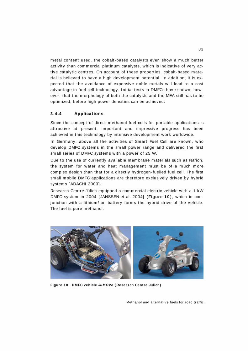
33
Methanol and alternative fuels for road traffic
metal content used, the cobalt-based catalysts even show a much better activity than commercial platinum catalysts, which is indicative of very ac-tive catalytic centres. On account of these properties, cobalt-based mate-rial is believed to have a high development potential. In addition, it is ex-pected that the avoidance of expensive noble metals will lead to a cost advantage in fuel cell technology. Initial tests in DMFCs have shown, how-ever, that the morphology of both the catalysts and the MEA still has to be optimized, before high power densities can be achieved.
3.4.4 Applications
Since the concept of direct methanol fuel cells for portable applications is attractive at present, important and impressive progress has been achieved in this technology by intensive development work worldwide.
In Germany, above all the activities of Smart Fuel Cell are known, who develop DMFC systems in the small power range and delivered the first small series of DMFC systems with a power of 25 W.
Due to the use of currently available membrane materials such as Nafion, the system for water and heat management must be of a much more complex design than that for a directly hydrogen-fuelled fuel cell. The first small mobile DMFC applications are therefore exclusively driven by hybrid systems [ADACHI 2003].
Research Centre Jülich equipped a commercial electric vehicle with a 1 kW DMFC system in 2004 [JANSSEN et al. 2004] (Figure 10), which in con-junction with a lithium/ion battery forms the hybrid drive of the vehicle. The fuel is pure methanol.
Figure 10: DMFC vehicle JuMOVe (Research Centre Jülich)
34
Methanol and alternative fuels for road traffic
3.4.5 Outlook
Direct methanol fuel cells are attractive for various applications, above all, however, as battery or accumulator replacement, since DMFC systems permit longer operating times due to the high energy density of methanol. Important and impressive progress has been made concerning this tech-nology due to intensive development work worldwide; however, the prop-erties of the materials currently available on the market, especially those of the membranes, are not optimal for application in DMFC systems. Fur-ther research and development is indispensable in order to realize direct methanol fuel cells and DMFC systems with high efficiencies and power densities. The potential of this technology can only be fully exploited with new optimized materials.
3.5 Methanol for fuel cell powered passenger cars in the USA
Against the background of fuel cell development, several industrial com-panies founded the international Methanol Fuel Cell Alliance (MFCA). Its aim was to create the prerequisites for building up a market for fuel cells and methanol as the energy carrier. This included the advancement of topics such as fuel cell specification, consumer acceptance (health, safety, environment), government funding of demonstration projects, establishing the infrastructure and training programmes. The MFCA comprises the companies Ballard/CDN, BASF/D, BP/GB, DaimlerChrysler/D/USA, Methanex/USA, and Statoil/N [MFCA 2003]. In addition, the Methanol Specification Council of the methanol, vehicle and oil industries has been established, which currently has a report drawn up on the environmental, safety and health problems of methanol for fuel cell power trains in com-parison to gasoline for internal combustion engines.
The California Fuel Cell Partnership (CaFCP) also supports the introduction of fuel cells in the motor vehicle market. CaFCP comprises fuel cell manu-facturers (Ballard Power Systems, UTC Fuel Cells), automobile manufac-turers (DaimlerChrysler, Ford Motor Company, General Motors, Honda, Hyundai, Nissan, Toyota, Volkswagen), power utilities (BP, Chevron, Tex-aco, ExxonMobil, Shell) and various American authorities. Concerning the fuel infrastructure, the associated members Air Products, Chemicals Inc. and Praxair are engaged in creating an infrastructure for hydrogen and Methanex one for methanol (a methanol filling station was opened in Sac-ramento on 24.4.2002). According to [CAFCP 2003], up to 70 passenger
35
Methanol and alternative fuels for road traffic
cars and buses as well as various filling stations are currently being incor-porated in a demonstration project. CaFCP already demonstrates the op-eration of hydrogen vehicles and plans to provide a “clean gasoline” as the third fuel (after hydrogen and methanol) and to demonstrate its applica-tion next year. “All car manufacturers in the CaFCP are in agreement that the first fuel cell vehicles that come onto the market will run on hydrogen from the filling station. Nevertheless, the members consider it important to further investigate all the fuels available” [LBSYS 2002].
3.6 Summary of Chapter 3
Vehicles with internal combustion engines for methanol (M85) are no lon-ger commercially available. In Europe, no market is in sight for vehicles with internal combustion engines or fuel cells (with or without reformer), for which methanol would have to be additionally supplied as a fuel. Automobile manufacturers make no declarations of intent concerning the provision of passenger cars or commercial vehicles for fuel cell methanol operation (only DaimlerChrysler made the NECAR-5 passenger car avail-able for a demonstration project within the framework of the California Fuel Cell Partnership, for which a methanol filling station was put into op-eration in Sacramento/CA in April 2002). No efforts at building up an in-frastructure for methanol supply for road traffic are currently perceivable in the EU.
Direct methanol fuel cells (DMFCs) directly convert the liquid fuel metha-nol into electric current. In comparison to fuel cell systems operated with pure hydrogen or hydrogen-rich gases from reforming processes, fuel supply is effected directly via liquid methanol. DMFCs are attractive for various applications, above all, however, as battery or accumulator re-placement, since DMFC systems permit longer operating times due to the high energy density of methanol. Important and impressive progress has been made concerning this technology due to intensive development work worldwide.

36
Methanol production
4 Methanol production
Methanol can be prepared in different ways. A method primarily used to-day is methanol synthesis following a synthesis gas production from natu-ral gas. Instead of natural gas it is also possible, in principle, to use coal, residual oils, oil, cellulose or other waste masses (cf. [SVZ 2001] and Table 7). Synthesis gas production may have to be preceded by an ex-tensive gas cleaning step, for example, if landfill gas is used; in these cases, methanol synthesis in small plants will not lead to economically ef-ficient solutions.
Another way of methanol preparation is synthesis from CO2 and H2. How-ever, this method only appears meaningful if, on the one hand, CO2 is pe-nalized and, on the other hand, hydrogen is produced from non-fossil sources. In this way, a “multiple use” of CO2 is possible (Figure 1). CO2 can be washed out from industrial gases; penalties and proceeds decide on the economic efficiency of the process.
Table 7: Methanol: feedstocks and potential use
Methanol
Feedstocks Potential use
Coal 1
Oil
Natural gas
Biomass 2 wood
sewage sludges
straw
miscanthus, etc.
Waste materials
Residual oils
Landfill gas
CO2 + H2 (renewable!)
Chemical raw material
MTBE (octane booster) Gasoline blend M85/M90, VM 3
M100 DI ICE 3 M100 FC 4
H2 production
Gasoline production: MTG 5 Protein production 6
1 From climate aspects, CO2 separation (capture) and sequestration are required; 2 Methanol (and diesel) from biomass [FREIBERG 2002]; 3 ICE = internal combustion engine; DI = direct injection; M85 passenger car in California and M100 programme in Germany and EPA/USA for ICE-DI diesel; 4 FC = fuel cell with electric motor in cars; methanol for on-board H2 production for PEFC or for direct use in DMFC; 5 MTG = methanol-to-gasoline (LURGI process); 6 Bacterially produced proteins for cattle fodder; ICI process (in the 70s) did not prove economically efficient
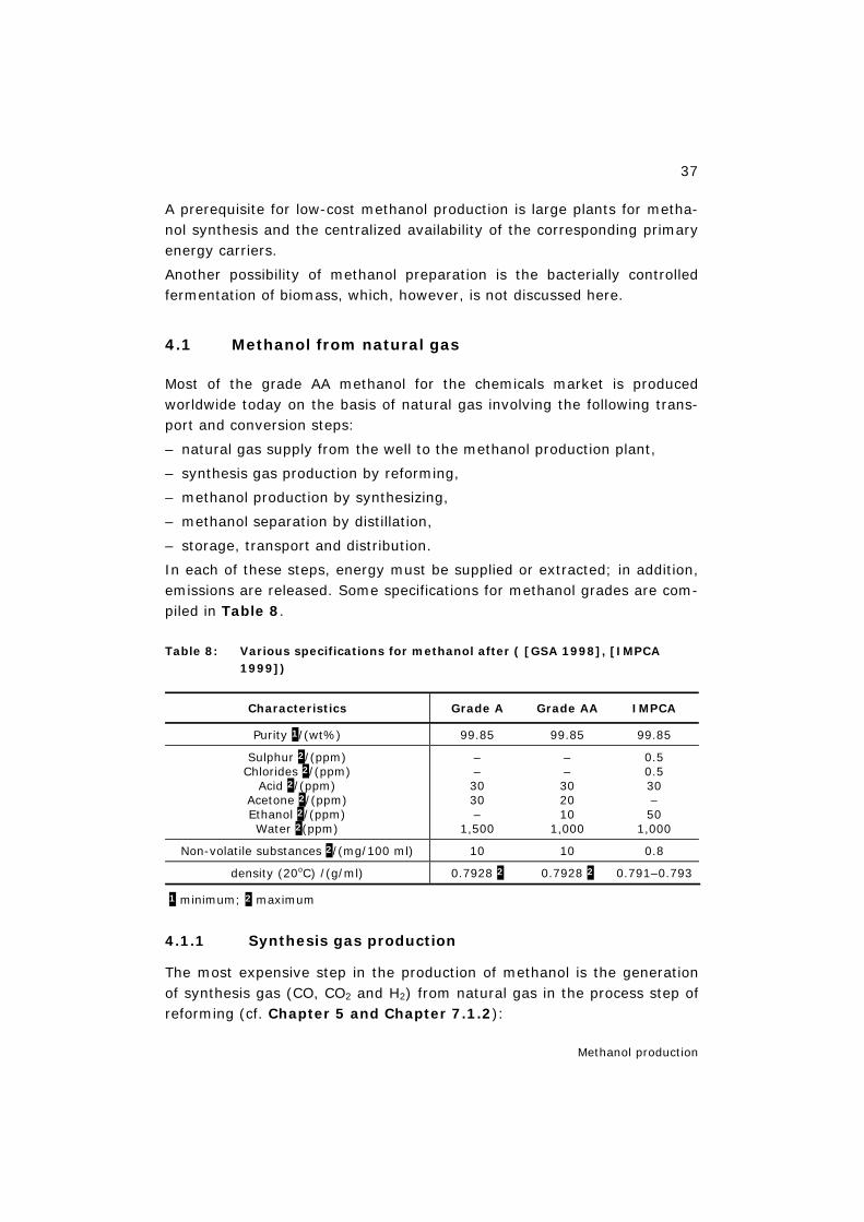
37
Methanol production
A prerequisite for low-cost methanol production is large plants for metha-nol synthesis and the centralized availability of the corresponding primary energy carriers.
Another possibility of methanol preparation is the bacterially controlled fermentation of biomass, which, however, is not discussed here.
4.1 Methanol from natural gas
Most of the grade AA methanol for the chemicals market is produced worldwide today on the basis of natural gas involving the following trans-port and conversion steps:
– natural gas supply from the well to the methanol production plant,
– synthesis gas production by reforming,
– methanol production by synthesizing,
– methanol separation by distillation,
– storage, transport and distribution.
In each of these steps, energy must be supplied or extracted; in addition, emissions are released. Some specifications for methanol grades are com-piled in Table 8.
Table 8: Various specifications for methanol after ( [GSA 1998], [IMPCA 1999])
Characteristics Grade A Grade AA IMPCA
Purity 1/(wt%) 99.85 99.85 99.85
Sulphur 2/(ppm) Chlorides 2/(ppm)
Acid 2/(ppm) Acetone 2/(ppm) Ethanol 2/(ppm) Water 2(ppm)
– – 30 30 –
1,500
– – 30 20 10
1,000
0.5 0.5 30 – 50
1,000
Non-volatile substances 2/(mg/100 ml) 10 10 0.8
density (20oC) /(g/ml) 0.7928 2 0.7928 2 0.791–0.793
1 minimum; 2 maximum
4.1.1 Synthesis gas production
The most expensive step in the production of methanol is the generation of synthesis gas (CO, CO2 and H2) from natural gas in the process step of reforming (cf. Chapter 5 and Chapter 7.1.2):
38
Methanol production
4 2 2
2 2 2
CH H O CO 3 H 205 kJ /molΔH
CO H O CO H ΔH 41 kJ /mol
+ ⇔ + = −−
+ ⇔ + − =
(eq. 4.1)
According to the state of the art, two processes mainly come into consid-eration here: conventional natural gas reforming (endothermal, heteroge-neously catalysed) with steam or carbon dioxide (CO2 can be imported into the plant) and the combination of conventional reforming with auto-thermal reforming (heterogeneously catalysed), in which the addition of oxygen is needed for the partial oxidation of natural gas.
Conventional natural gas steam reforming with CO2 addition at tempera-tures of up to 850 °C and pressures between 15 and 25 bars provides synthesis gases which are not optimally suited for methanol synthesis due to the hydrogen surplus; therefore, carbon dioxide may be added before or after reforming. In combined reforming, the synthesis gas optimal for methanol synthesis can be produced without the addition of CO2 and in comparison to conventional reforming even with less investment and total energy expenditure.
In the synthesis gas production process with combined reforming (Figure 11), after desulphurization part of the process natural gas is re-formed in the reforming unit heated with natural gas at a temperature of 800 °C and a pressure of about 34 bars. The gas is further reformed to-gether with the remaining desulphurized natural gas in the autothermal reforming unit at 960 °C and 33 bars. The heat required for this purpose is made available by the partial combustion of the gas with oxygen. The residual methane content in the synthesis gas is lower and the apparatus expenditure less than in the case of conventional reforming.
4.1.2 Methanol synthesis
The synthesis gas is converted into methanol and water in a heterogene-ously catalysed reaction system:
(eq. 4.2)
The conversion of CO, CO2 and H2 into methanol and water is an exother-mal process, which preferentially takes place at temperatures of 220–280 °C and a pressure of 40–110 bars with the catalysts available today; this conversion of CO and CO2 into CH3OH is characterized by the carbon conversion rate, which is defined as the ratio of the number of produced CH3OH moles to the number of consumed moles (CO + CO2). It rises with
2 3
2 2 3 2
CO 2H CH OH ΔH 91 kJ /mol
CO 3H CH OH H O ΔH 49 kJ /mol
+ ⇔ − =
+ ⇔ + − =
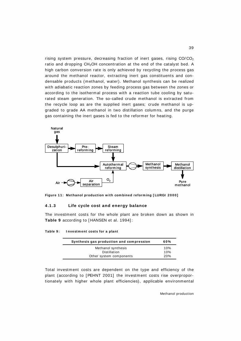
39
Methanol production
rising system pressure, decreasing fraction of inert gases, rising CO/CO2 ratio and dropping CH3OH concentration at the end of the catalyst bed. A high carbon conversion rate is only achieved by recycling the process gas around the methanol reactor, extracting inert gas constituents and con-densable products (methanol, water). Methanol synthesis can be realized with adiabatic reaction zones by feeding process gas between the zones or according to the isothermal process with a reaction tube cooling by satu-rated steam generation. The so-called crude methanol is extracted from the recycle loop as are the supplied inert gases; crude methanol is up-graded to grade AA methanol in two distillation columns, and the purge gas containing the inert gases is fed to the reformer for heating.
Figure 11: Methanol production with combined reforming [LURGI 2000]
4.1.3 Life cycle cost and energy balance
The investment costs for the whole plant are broken down as shown in Table 9 according to [HANSEN et al. 1994]:
Table 9: Investment costs for a plant
Synthesis gas production and compression 60%
Methanol synthesis Distillation
Other system components
10% 10% 20%
Total investment costs are dependent on the type and efficiency of the plant (according to [PEHNT 2001] the investment costs rise overpropor-tionately with higher whole plant efficiencies), applicable environmental
Air Air separation
Autothermal reforming
Methanol synthesis
Methanol distillation
Puremethanol
Desulphuri-zation
Pre-reforming
Steamreforming
Naturalgas
O2Air Air
separation
Autothermal reforming
Methanol synthesis
Methanol distillation
Puremethanol
Desulphuri-zation
Pre-reforming
Steamreforming
Naturalgas
O2
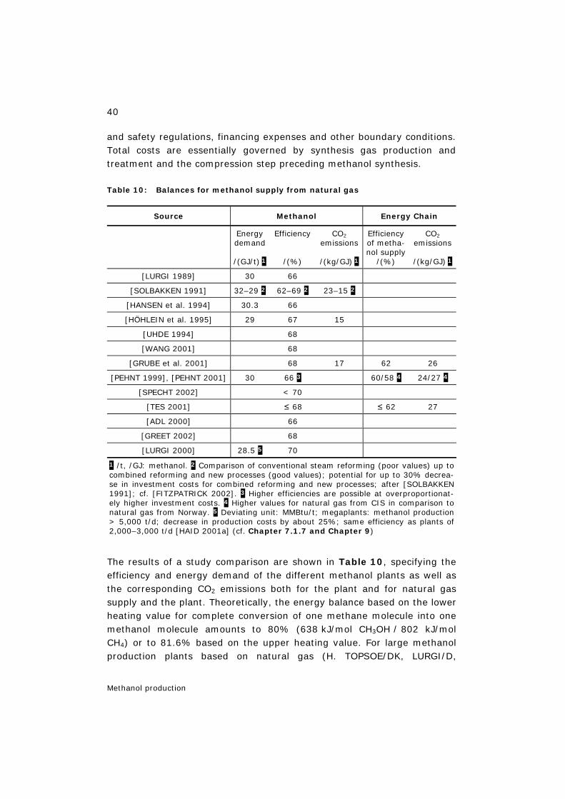
40
Methanol production
and safety regulations, financing expenses and other boundary conditions. Total costs are essentially governed by synthesis gas production and treatment and the compression step preceding methanol synthesis.
Table 10: Balances for methanol supply from natural gas
Source Methanol Energy Chain
Energy demand
/(GJ/t) 1
Efficiency
/(%)
CO2 emissions
/(kg/GJ) 1
Efficiency of metha-nol supply
/(%)
CO2 emissions
/(kg/GJ) 1
[LURGI 1989] 30 66
[SOLBAKKEN 1991] 32–29 2 62–69 2 23–15 2
[HANSEN et al. 1994] 30.3 66
[HÖHLEIN et al. 1995] 29 67 15
[UHDE 1994] 68
[WANG 2001] 68
[GRUBE et al. 2001] 68 17 62 26
[PEHNT 1999], [PEHNT 2001] 30 66 3 60/58 4 24/27 4
[SPECHT 2002] < 70
[TES 2001] ≤ 68 ≤ 62 27
[ADL 2000] 66
[GREET 2002] 68
[LURGI 2000] 28.5 5 70
1 /t, /GJ: methanol. 2 Comparison of conventional steam reforming (poor values) up to combined reforming and new processes (good values); potential for up to 30% decrea-se in investment costs for combined reforming and new processes; after [SOLBAKKEN 1991]; cf. [FITZPATRICK 2002]. 3 Higher efficiencies are possible at overproportionat-ely higher investment costs. 4 Higher values for natural gas from CIS in comparison to natural gas from Norway. 5 Deviating unit: MMBtu/t; megaplants: methanol production > 5,000 t/d; decrease in production costs by about 25%; same efficiency as plants of 2,000–3,000 t/d [HAID 2001a] (cf. Chapter 7.1.7 and Chapter 9)
The results of a study comparison are shown in Table 10, specifying the efficiency and energy demand of the different methanol plants as well as the corresponding CO2 emissions both for the plant and for natural gas supply and the plant. Theoretically, the energy balance based on the lower heating value for complete conversion of one methane molecule into one methanol molecule amounts to 80% (638 kJ/mol CH3OH / 802 kJ/mol CH4) or to 81.6% based on the upper heating value. For large methanol production plants based on natural gas (H. TOPSOE/DK, LURGI/D,
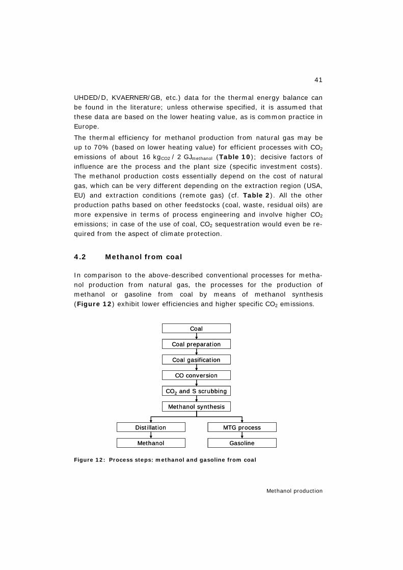
41
Methanol production
UHDED/D, KVAERNER/GB, etc.) data for the thermal energy balance can be found in the literature; unless otherwise specified, it is assumed that these data are based on the lower heating value, as is common practice in Europe.
The thermal efficiency for methanol production from natural gas may be up to 70% (based on lower heating value) for efficient processes with CO2 emissions of about 16 kgCO2 / 2 GJmethanol (Table 10); decisive factors of influence are the process and the plant size (specific investment costs). The methanol production costs essentially depend on the cost of natural gas, which can be very different depending on the extraction region (USA, EU) and extraction conditions (remote gas) (cf. Table 2). All the other production paths based on other feedstocks (coal, waste, residual oils) are more expensive in terms of process engineering and involve higher CO2 emissions; in case of the use of coal, CO2 sequestration would even be re-quired from the aspect of climate protection.
4.2 Methanol from coal
In comparison to the above-described conventional processes for metha-nol production from natural gas, the processes for the production of methanol or gasoline from coal by means of methanol synthesis (Figure 12) exhibit lower efficiencies and higher specific CO2 emissions.
Figure 12: Process steps: methanol and gasoline from coal
Coal
Coal preparation
Coal gasification
CO conversion
CO2 and S scrubbing
Methanol synthesis
MTG process
Gasoline
Distillation
Methanol
Coal
Coal preparation
Coal gasification
CO conversion
CO2 and S scrubbing
Methanol synthesis
MTG process
Gasoline
Distillation
Methanol
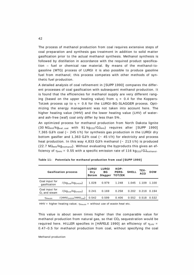
42
Methanol production
The process of methanol production from coal requires extensive steps of coal preparation and synthesis gas treatment in addition to solid matter gasification prior to the actual methanol synthesis. Methanol synthesis is followed by distillation in accordance with the required product specifica-tion – fuel or chemical raw material. By means of the methanol-to-gasoline (MTG) process of LURGI it is also possible to produce gasoline fuel from methanol; this process competes with other methods of syn-thetic fuel production.
A detailed analysis of coal refinement in [SUPP 1990] compares the differ-ent processes of coal gasification with subsequent methanol production. It is found that the efficiencies for methanol supply are very different rang-ing (based on the upper heating value) from η = 0.4 for the Koppers-Totzek process up to η = 0.6 for the LURGI-BG-SLAGGER process. Opti-mizing the energy management was not taken into account here. The higher heating value (HHV) and the lower heating value (LHV) of water- and ash-free (waf) coal only differ by less than 5%.
An optimized process for methanol production from North Dakota lignite (30 MJHHV/kgwaf, coal with 91 kgCO2/GJHHV) requires after [SUPP 1990] 7,365 GJ/h coal (~ 245 t/h) for synthesis gas production in the LURGI dry bottom gasifier and 1,363 GJ/h coal (~ 45 t/h) for electricity and process heat production. In this way 4,833 GJ/h methanol (~ 213 t/h) is produced (22.7 MJHHV/kgmethanol). Without evaluating the byproducts this gives an ef-ficiency of ηHHV = 0.55 with a specific emission rate of 116 kgCO2/GJmethanol.
Table 11: Potentials for methanol production from coal [SUPP 1990]
Gasification process LURGI
Dry Botom
LURGI BG
Slagger
KOP-PERS-
TOTZEK SHELL TEX-
ACO DOW
Coal input for gasification
/(kgcoal/kgCH3OH) 1.028 0.979 1.248 1.045 1.109 1.100
Coal input for O2 and steam
/(kgcoal/kgCH3OH) 0.241 0.169 0.258 0.202 0.219 0.194
ηPseudo /(HHVCH3OH/HHVcoal) 0.542 0.599 0.406 0.552 0.518 0.532
HHV = higher heating value; ηPseudo = without use of waste heat etc.
This value is about seven times higher than the comparable value for methanol production from natural gas, so that CO2 sequestration would be required here. HILLER specifies in [HÄFELE 1990] an efficiency of ηLHV = 0.47–0.5 for methanol production from coal, without specifying the coal
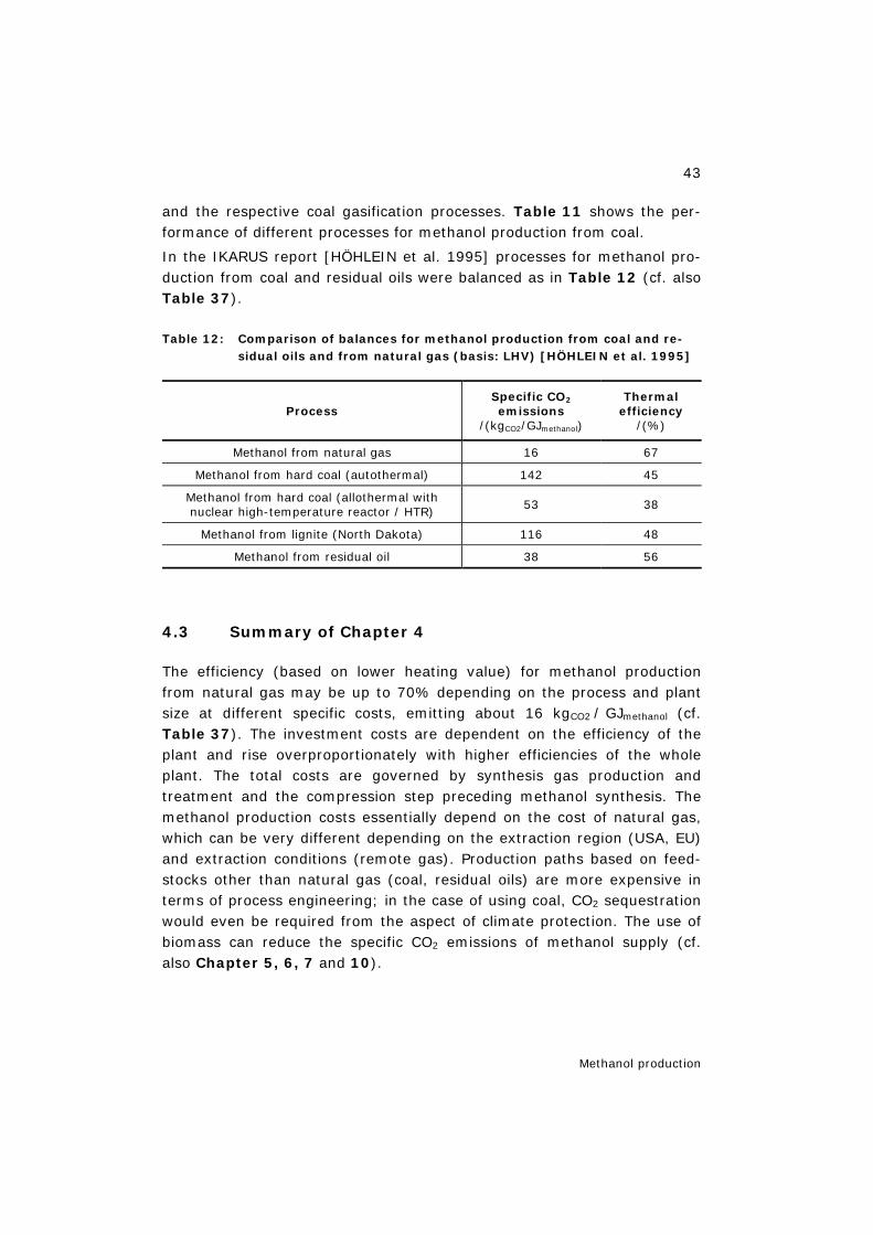
43
Methanol production
and the respective coal gasification processes. Table 11 shows the per-formance of different processes for methanol production from coal.
In the IKARUS report [HÖHLEIN et al. 1995] processes for methanol pro-duction from coal and residual oils were balanced as in Table 12 (cf. also Table 37).
Table 12: Comparison of balances for methanol production from coal and re-sidual oils and from natural gas (basis: LHV) [HÖHLEIN et al. 1995]
Process
Specific CO2 emissions
/(kgCO2/GJmethanol)
Thermal efficiency
/(%)
Methanol from natural gas 16 67 Methanol from hard coal (autothermal) 142 45
Methanol from hard coal (allothermal with nuclear high-temperature reactor / HTR) 53 38
Methanol from lignite (North Dakota) 116 48 Methanol from residual oil 38 56
4.3 Summary of Chapter 4
The efficiency (based on lower heating value) for methanol production from natural gas may be up to 70% depending on the process and plant size at different specific costs, emitting about 16 kgCO2 / GJmethanol (cf. Table 37). The investment costs are dependent on the efficiency of the plant and rise overproportionately with higher efficiencies of the whole plant. The total costs are governed by synthesis gas production and treatment and the compression step preceding methanol synthesis. The methanol production costs essentially depend on the cost of natural gas, which can be very different depending on the extraction region (USA, EU) and extraction conditions (remote gas). Production paths based on feed-stocks other than natural gas (coal, residual oils) are more expensive in terms of process engineering; in the case of using coal, CO2 sequestration would even be required from the aspect of climate protection. The use of biomass can reduce the specific CO2 emissions of methanol supply (cf. also Chapter 5, 6, 7 and 10).

44
Synthesis gas
5 Synthesis gas 5
5.1 Applications
5.1.1 Principles
Synthesis gas (syngas) is a mixture of hydrogen, carbon monoxide, and carbon dioxide. It may also contain nitrogen as applied for the ammonia synthesis. Syngas is a key intermediate in the chemical industry. It is used in a number of highly selective syntheses of a wide range of chemi-cals and fuels, and as a source of pure hydrogen and carbon monoxide.
The present use is primarily for the manufacture of ammonia (2000: 120 million t/y) and of methanol (2000: 30 million t/y) followed by the use of pure hydrogen for hydrotreating in refineries. Other applications are for synthesis of higher alcohols (by hydroformulation), hydrogenation of unsaturated compounds and direct reduction of iron ore.
Synthesis gas can be produced from almost any carbon source ranging from natural gas and oil products to coal and biomass by oxidation with steam and oxygen. Hence it represents a key for creating flexibility for the chemical industry and for the manufacture of synthetic fuels (synfuels).
Natural gas Naphta Coal Biomass
O2, H2O “Syngas”
“Products + heat”
In most plants, the heat is utilized for running the plant. This requires that the heat is available at sufficiently high temperature to raise high-pressure steam.
5.1.2 Natural gas conversion
The future use of syngas is dominated by the conversion of cheap natural gas into liquid fuels, gas to liquids (GTL). This is natural gas at remote loca-tions (”stranded natural gas”) with no market for electricity and too far away to justify a pipeline. Another topic is a possible role of syngas technol-ogy in a future ”hydrogen economy” not the least associated with the use of fuel cells. These trends imply on the one hand the scale-up to very large-scale GTL plants (above 500,000 Nm3
syngas/h) and on the other hand the
5 Chapter 5 sources: figures after Rostrup-Nielsen (HTAS), 2005.
45
Synthesis gas
scale-down to small hydrogen units for fuel cells (5–100 Nm3syngas/h). This
creates new challenges to the technology and the involved catalysis.
The conversion of natural GTL products has been discussed for decades and recently as a solution for the validation of ”stranded natural gas”, as the liquid fuels can be moved readily around the world to markets where they are most needed. So far, projects involving liquified natural gas (LNG) have typically proven to be more feasible. The gas conversion (GTL) has suffered from small price differential between the product and natural gas. The regulation prohibiting flaring of natural gas (typically associated gas at oil fields) as well as lower investments in the GTL plants has changed this picture. About 3% of the natural gas production is flared which corresponds to ca. 200 million tCO2/y or about 0.7% of the total world CO2 production. With flaring of natural gas being prohibited, the real price of natural gas at these remote areas may even be negative in view of the costs of reinjection in the oil fields.
The manufacture of synfuels via syngas was applied in Germany during World War II with nine plants based on Fischer-Tropsch (FT) synthesis with a total capacity amounting to 700,000 t/y (ca. 7,000 bpd). The syn-gas was made by coal gasification as also for the original FT units in South Africa (Sasolburg, Secunda). The manufacture of synfuels from natural gas is technically feasible as demonstrated by the methanol to gasoline (MTG) plant in New Zealand, and the FT units in Malaysia and Mossel Bay, South Africa. Further units are under design in Nigeria and Qatar by Sasol (each about 30,000 bpd). Shell has announced units in Qatar with a ca-pacity of 70,000 bpd and recently Exxon Mobil announced another plant in Qatar with a capacity of 150,000 bpd.
Hydrogen is an energy carrier resulting in great flexibility as it can be manufactured from a variety of energy sources. In addition, the environ-mental prospects of a hydrogen economy are great. A hydrogen economy based on fossil fuels may well solve local environmental problems (smog, NOx etc.), but will still result in CO2 missions. Hence, significant efforts are being made to develop technologies for hydrogen production based on fossil fuels combined with CO2 sequestration. The aim is to develop effec-tive methods to capture significant amounts of CO2 from power generation and store the CO2 in geological formations. Figure 13 shows a scheme for large-scale power production based on air-blown reforming of natural gas coupled to CO2 sequestration. It is essential that CO2 is captured at as high a pressure as possible since CO2 absorption from flue gas will be very energy requiring.
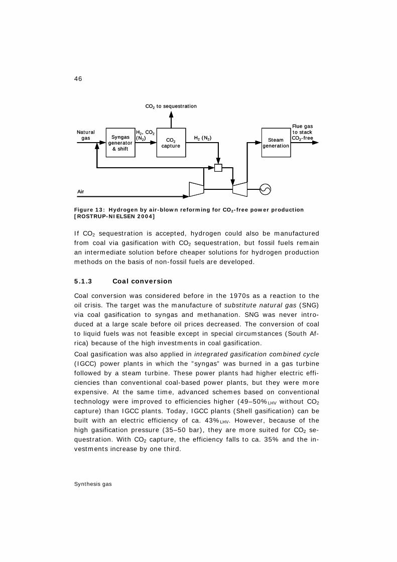
46
Synthesis gas
Figure 13: Hydrogen by air-blown reforming for CO2-free power production [ROSTRUP-NIELSEN 2004]
If CO2 sequestration is accepted, hydrogen could also be manufactured from coal via gasification with CO2 sequestration, but fossil fuels remain an intermediate solution before cheaper solutions for hydrogen production methods on the basis of non-fossil fuels are developed.
5.1.3 Coal conversion
Coal conversion was considered before in the 1970s as a reaction to the oil crisis. The target was the manufacture of substitute natural gas (SNG) via coal gasification to syngas and methanation. SNG was never intro-duced at a large scale before oil prices decreased. The conversion of coal to liquid fuels was not feasible except in special circumstances (South Af-rica) because of the high investments in coal gasification.
Coal gasification was also applied in integrated gasification combined cycle (IGCC) power plants in which the ”syngas” was burned in a gas turbine followed by a steam turbine. These power plants had higher electric effi-ciencies than conventional coal-based power plants, but they were more expensive. At the same time, advanced schemes based on conventional technology were improved to efficiencies higher (49–50%LHV without CO2 capture) than IGCC plants. Today, IGCC plants (Shell gasification) can be built with an electric efficiency of ca. 43%LHV. However, because of the high gasification pressure (35–50 bar), they are more suited for CO2 se-questration. With CO2 capture, the efficiency falls to ca. 35% and the in-vestments increase by one third.
CO2 to sequestration
Steamgeneration
Syngasgenerator
& shift
CO2capture
Naturalgas
H2, CO2(N2) H2 (N2)
Air
Flue gasto stackCO2-free
CO2 to sequestration
Steamgeneration
Syngasgenerator
& shift
CO2capture
Naturalgas
H2, CO2(N2) H2 (N2)
Air
Flue gasto stackCO2-free
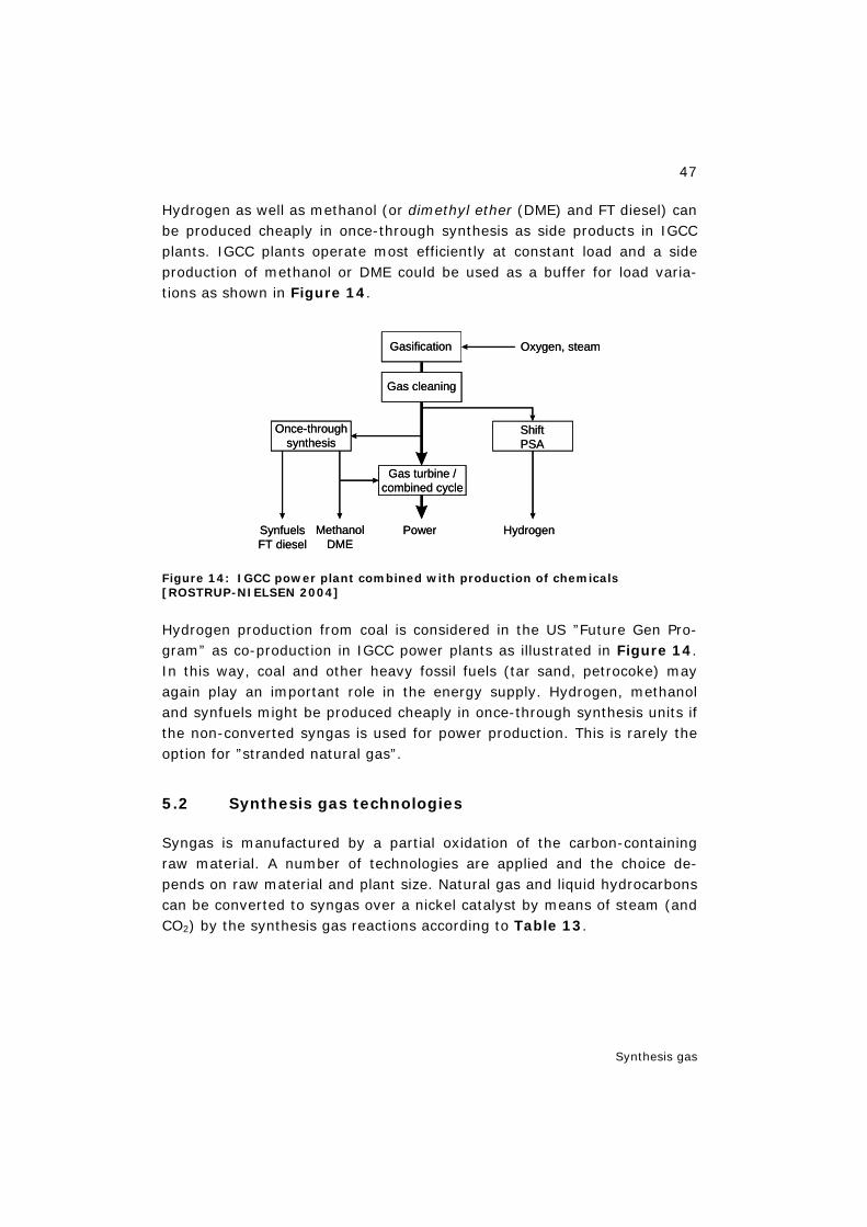
47
Synthesis gas
Hydrogen as well as methanol (or dimethyl ether (DME) and FT diesel) can be produced cheaply in once-through synthesis as side products in IGCC plants. IGCC plants operate most efficiently at constant load and a side production of methanol or DME could be used as a buffer for load varia-tions as shown in Figure 14.
Figure 14: IGCC power plant combined with production of chemicals [ROSTRUP-NIELSEN 2004]
Hydrogen production from coal is considered in the US ”Future Gen Pro-gram” as co-production in IGCC power plants as illustrated in Figure 14. In this way, coal and other heavy fossil fuels (tar sand, petrocoke) may again play an important role in the energy supply. Hydrogen, methanol and synfuels might be produced cheaply in once-through synthesis units if the non-converted syngas is used for power production. This is rarely the option for ”stranded natural gas”.
5.2 Synthesis gas technologies
Syngas is manufactured by a partial oxidation of the carbon-containing raw material. A number of technologies are applied and the choice de-pends on raw material and plant size. Natural gas and liquid hydrocarbons can be converted to syngas over a nickel catalyst by means of steam (and CO2) by the synthesis gas reactions according to Table 13.
Once-throughsynthesis
Gas turbine /combined cycle
Gas cleaning
Gasification Oxygen, steam
HydrogenPowerMethanolDME
SynfuelsFT diesel
ShiftPSA
Once-throughsynthesis
Gas turbine /combined cycle
Gas cleaning
Gasification Oxygen, steam
HydrogenPowerMethanolDME
SynfuelsFT diesel
ShiftPSA
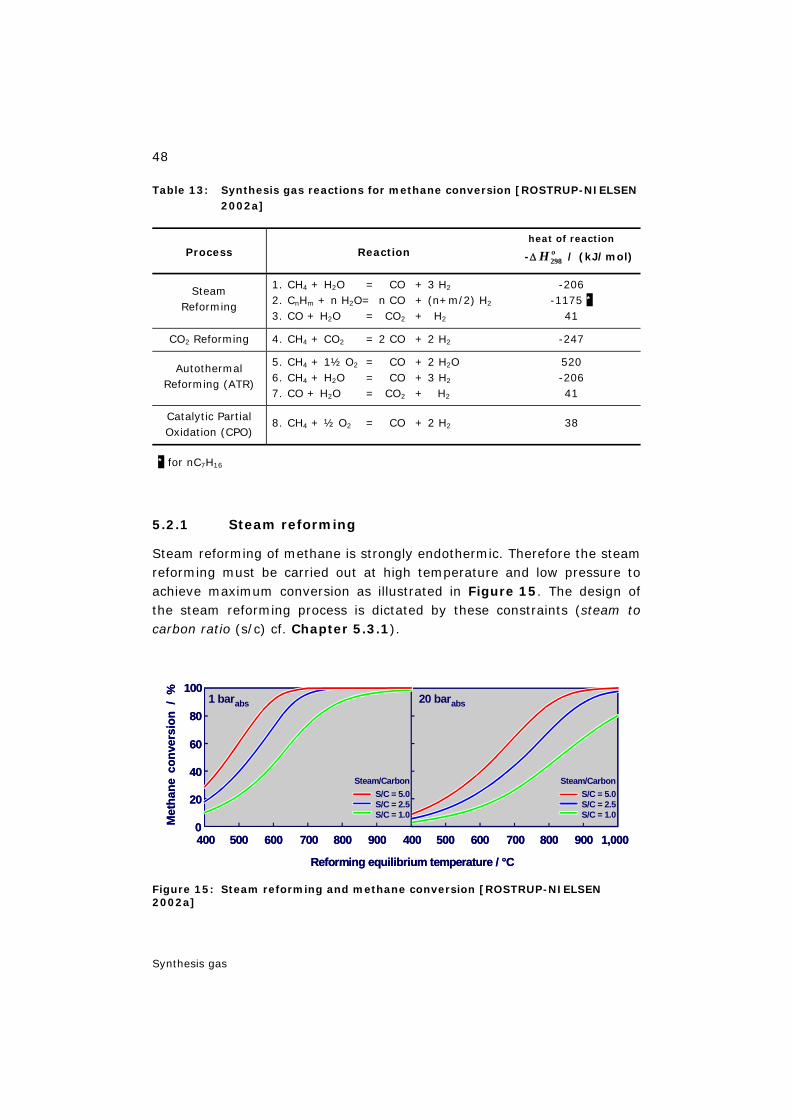
48
Synthesis gas
Table 13: Synthesis gas reactions for methane conversion [ROSTRUP-NIELSEN 2002a]
Process Reaction heat of reaction
-Δ oH 298 / (kJ/mol)
Steam Reforming
1. CH4 + H2O = CO + 3 H2
2. CnHm + n H2O= n CO + (n+m/2) H2 3. CO + H2O = CO2 + H2
-206 -1175 *
41
CO2 Reforming 4. CH4 + CO2 = 2 CO + 2 H2 -247
Autothermal Reforming (ATR)
5. CH4 + 1½ O2 = CO + 2 H2O 6. CH4 + H2O = CO + 3 H2
7. CO + H2O = CO2 + H2
520 -206 41
Catalytic Partial Oxidation (CPO)
8. CH4 + ½ O2 = CO + 2 H2 38
* for nC7H16
5.2.1 Steam reforming
Steam reforming of methane is strongly endothermic. Therefore the steam reforming must be carried out at high temperature and low pressure to achieve maximum conversion as illustrated in Figure 15. The design of the steam reforming process is dictated by these constraints (steam to carbon ratio (s/c) cf. Chapter 5.3.1).
Figure 15: Steam reforming and methane conversion [ROSTRUP-NIELSEN 2002a]
400 500 600 700 800 900 400 500 600 700 800 900
S/C = 5.0S/C = 2.5S/C = 1.0
S/C = 5.0S/C = 2.5S/C = 1.0
Reforming equilibrium temperature / °C
0
20
40
60
80
100
Met
hane
conv
ersi
on/
%
1 bar abs 20 bar abs
1,000
Steam/Carbon Steam/Carbon
400 500 600 700 800 900 400 500 600 700 800 900
S/C = 5.0S/C = 2.5S/C = 1.0
S/C = 5.0S/C = 2.5S/C = 1.0
Reforming equilibrium temperature / °C
0
20
40
60
80
100
Met
hane
conv
ersi
on/
%
1 bar abs 20 bar abs
1,000
Steam/Carbon Steam/Carbon
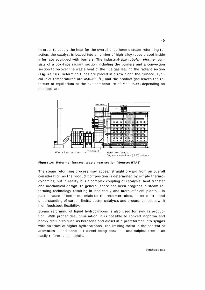
49
Synthesis gas
In order to supply the heat for the overall endothermic steam reforming re-action, the catalyst is loaded into a number of high-alloy tubes placed inside a furnace equipped with burners. The industrial-size tubular reformer con-sists of a box-type radiant section including the burners and a convection section to recover the waste heat of the flue gas leaving the radiant section (Figure 16). Reforming tubes are placed in a row along the furnace. Typi-cal inlet temperatures are 450–650oC, and the product gas leaves the re-former at equilibrium at the exit temperature of 700–950oC depending on the application.
Figure 16: Reformer furnace. Waste heat section (Source: HTAS)
The steam reforming process may appear straightforward from an overall consideration as the product composition is determined by simple thermo-dynamics, but in reality it is a complex coupling of catalysis, heat transfer and mechanical design. In general, there has been progress in steam re-forming technology resulting in less costly and more efficient plants – in part because of better materials for the reformer tubes, better control and understanding of carbon limits, better catalysts and process concepts with high feedstock flexibility.
Steam reforming of liquid hydrocarbons is also used for syngas produc-tion. With proper desulphurisation, it is possible to convert naphtha and heavy distillates such as kerosene and diesel in a prereformer into syngas with no trace of higher hydrocarbons. The limiting factor is the content of aromatics – and hence FT diesel being paraffinic and sulphur-free is as easily reformed as naphtha.
Waste heat section Reformer furnaceOnly every second tube (of 66) is shown
Waste heat section Reformer furnaceOnly every second tube (of 66) is shown
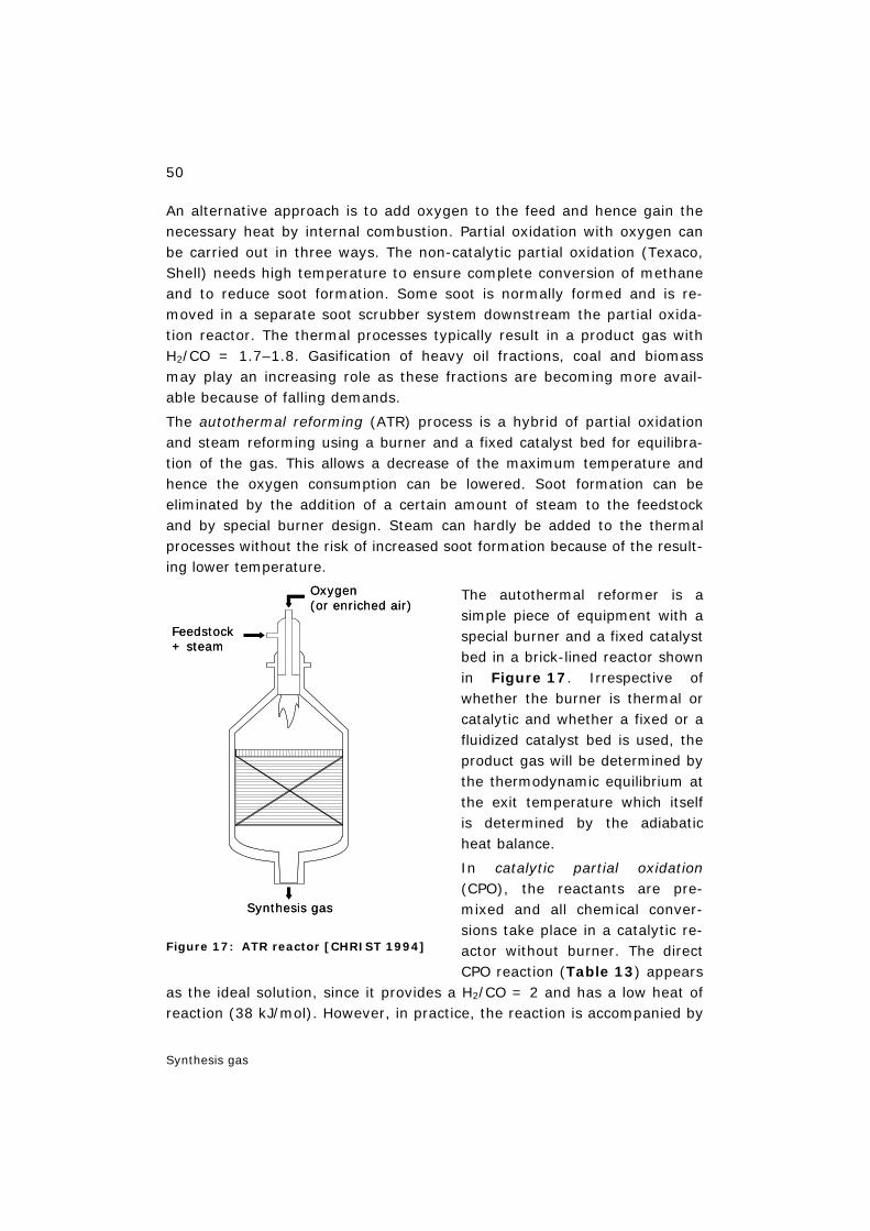
50
Synthesis gas
An alternative approach is to add oxygen to the feed and hence gain the necessary heat by internal combustion. Partial oxidation with oxygen can be carried out in three ways. The non-catalytic partial oxidation (Texaco, Shell) needs high temperature to ensure complete conversion of methane and to reduce soot formation. Some soot is normally formed and is re-moved in a separate soot scrubber system downstream the partial oxida-tion reactor. The thermal processes typically result in a product gas with H2/CO = 1.7–1.8. Gasification of heavy oil fractions, coal and biomass may play an increasing role as these fractions are becoming more avail-able because of falling demands.
The autothermal reforming (ATR) process is a hybrid of partial oxidation and steam reforming using a burner and a fixed catalyst bed for equilibra-tion of the gas. This allows a decrease of the maximum temperature and hence the oxygen consumption can be lowered. Soot formation can be eliminated by the addition of a certain amount of steam to the feedstock and by special burner design. Steam can hardly be added to the thermal processes without the risk of increased soot formation because of the result-ing lower temperature.
The autothermal reformer is a simple piece of equipment with a special burner and a fixed catalyst bed in a brick-lined reactor shown in Figure 17. Irrespective of whether the burner is thermal or catalytic and whether a fixed or a fluidized catalyst bed is used, the product gas will be determined by the thermodynamic equilibrium at the exit temperature which itself is determined by the adiabatic heat balance.
In catalytic partial oxidation (CPO), the reactants are pre-mixed and all chemical conver-sions take place in a catalytic re-actor without burner. The direct CPO reaction (Table 13) appears
as the ideal solution, since it provides a H2/CO = 2 and has a low heat of reaction (38 kJ/mol). However, in practice, the reaction is accompanied by
Figure 17: ATR reactor [CHRIST 1994]
Oxygen(or enriched air)
Feedstock+ steam
Synthesis gas
Oxygen(or enriched air)
Feedstock+ steam
Synthesis gas
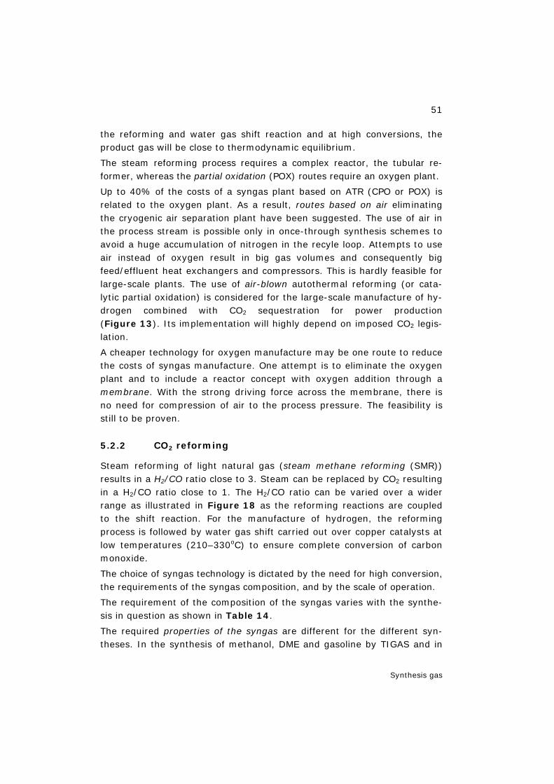
51
Synthesis gas
the reforming and water gas shift reaction and at high conversions, the product gas will be close to thermodynamic equilibrium.
The steam reforming process requires a complex reactor, the tubular re-former, whereas the partial oxidation (POX) routes require an oxygen plant.
Up to 40% of the costs of a syngas plant based on ATR (CPO or POX) is related to the oxygen plant. As a result, routes based on air eliminating the cryogenic air separation plant have been suggested. The use of air in the process stream is possible only in once-through synthesis schemes to avoid a huge accumulation of nitrogen in the recyle loop. Attempts to use air instead of oxygen result in big gas volumes and consequently big feed/effluent heat exchangers and compressors. This is hardly feasible for large-scale plants. The use of air-blown autothermal reforming (or cata-lytic partial oxidation) is considered for the large-scale manufacture of hy-drogen combined with CO2 sequestration for power production (Figure 13). Its implementation will highly depend on imposed CO2 legis-lation.
A cheaper technology for oxygen manufacture may be one route to reduce the costs of syngas manufacture. One attempt is to eliminate the oxygen plant and to include a reactor concept with oxygen addition through a membrane. With the strong driving force across the membrane, there is no need for compression of air to the process pressure. The feasibility is still to be proven.
5.2.2 CO2 reforming
Steam reforming of light natural gas (steam methane reforming (SMR)) results in a H2/CO ratio close to 3. Steam can be replaced by CO2 resulting in a H2/CO ratio close to 1. The H2/CO ratio can be varied over a wider range as illustrated in Figure 18 as the reforming reactions are coupled to the shift reaction. For the manufacture of hydrogen, the reforming process is followed by water gas shift carried out over copper catalysts at low temperatures (210–330oC) to ensure complete conversion of carbon monoxide.
The choice of syngas technology is dictated by the need for high conversion, the requirements of the syngas composition, and by the scale of operation.
The requirement of the composition of the syngas varies with the synthe-sis in question as shown in Table 14.
The required properties of the syngas are different for the different syn-theses. In the synthesis of methanol, DME and gasoline by TIGAS and in
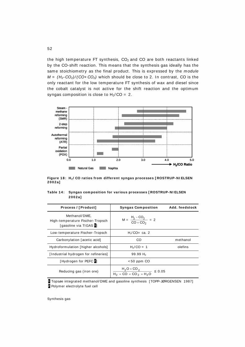
52
Synthesis gas
the high temperature FT synthesis, CO2 and CO are both reactants linked by the CO-shift reaction. This means that the synthesis gas ideally has the same stoichiometry as the final product. This is expressed by the module M = (H2-CO2)/(CO+CO2) which should be close to 2. In contrast, CO is the only reactant for the low temperature FT synthesis of wax and diesel since the cobalt catalyst is not active for the shift reaction and the optimum syngas composition is close to H2/CO = 2.
Figure 18: H2/CO ratios from different syngas processes [ROSTRUP-NIELSEN 2002a]
Table 14: Syngas composition for various processes [ROSTRUP-NIELSEN 2002a]
Process /[Product] Syngas Composition Add. feedstock
Methanol/DME, High-temperature Fischer-Tropsch
[gasoline via TIGAS 1]
M = 2
22COCO
COH
+
- = 2
Low-temperature Fischer-Tropsch H2/CO= ca. 2
Carbonylation [acetic acid] CO methanol
Hydroformulation [higher alcohols] H2/CO = 1 olefins
[Industrial hydrogen for refineries] 99.99 H2
[Hydrogen for PEFC 2] <50 ppm CO
Reducing gas (iron ore) OHCOCOH
COOH
222
22+++
+ ≤ 0.05
1 Topsøe integrated methanol/DME and gasoline synthesis [TOPP-JØRGENSEN 1987] 2 Polymer electrolyte fuel cell
Steam -methane
reforming(SMR)
2-stepreforming
Autothermalreforming
(ATR)
Partialoxidation
(POX)
Natural Gas NaphtaH2/CO Ratio
0.0 1.0 2.0 3.0 4.0 5.0
Steam -methane
reforming(SMR)
2-stepreforming
Autothermalreforming
(ATR)
Partialoxidation
(POX)
Natural Gas NaphtaH2/CO Ratio
0.0 1.0 2.0 3.0 4.0 5.0
53
Synthesis gas
5.3 Synthesis gas for methanol
5.3.1 Stoichiometry
The synthesis gas for methanol should ideally have the same stoichiome-try as the final product. This is expressed by the module M which should be close to 2 as shown in Table 14: M = (H2-CO2)/(CO+CO2) = 2. M > 2 means too much, M < 2 means too little hydrogen in the syngas.
Figure 19 shows the H2/CO ratio and the module M obtained from lean natural gas by ATR as function of the steam to carbon ratio (S/C) and the exit temperature. Although certain adjustments are possible, direct prod-uction by ATR of a gas with a module M = 2 is impossible. Such gases are best produced by a combination of steam reforming and oxygen-fired sec-ondary reforming or, for very large capacities, by ATR followed by adjust-ment of the gas composition by the addition of H2 and/or removal of CO2 .
Feed preheat temperature 550oC, no prereformer.
Figure 19: Module M and H2/CO in raw gas from ATR [CHRIST 1998]
Liquid hydrocarbons have a lower H/C ratio than CH4 meaning less re-quirement of CO2 for meeting the module M=2. The feasibility of CO2 re-forming depends strongly on the price (and pressure) of the CO2 source. Many natural gas resources as well as biogas contain large quantities of CO2.
2
2
2CΟCΟ
CΟΗ -
+
H2/CO, 950°C
M = , 950°C
2
2
2CΟCΟ
CΟΗ -
+M = , 1050°C
H2/CO, 1050°C
2.0
2.01.00.0
S/C Ratio
M, H
2/CO
Rat
io
2
2
2CΟCΟ
CΟΗ -
+
H2/CO, 950°C
M = , 950°C
2
2
2CΟCΟ
CΟΗ -
+M = , 1050°C
H2/CO, 1050°C
2.0
2.01.00.0
S/C Ratio
M, H
2/CO
Rat
io

54
Synthesis gas
5.3.2 Choice of technology
The choice of technology for the manufacture of synthesis gas depends on the scale of operation. For methanol, tubular reforming would be cheapest at a capacity below 1,000–1,500 MTPD, whereas the autothermal reform-ing is favoured at capacities above about 6,000 MTPD. This is caused by the economy of scale being different for the tubular reformer and the oxy-gen plant as illustrated in Figure 20.
Figure 20: Impact of economy of scale [ROSTRUP-NIELSEN 2000a]
For the intermediate range representing the capacity of world-scale methanol plants, a combination of tubular reforming and a secondary oxygen-blown reformer is normally the optimum solution. Figure 21 shows the two-step reforming unit in a 2,500 MTPD methanol plant.
Syngas with M=2 cannot be produced directly by steam reforming of natu-ral gas. The surplus hydrogen is recycled to the reformer as fuel. How-ever, combined steam and CO2 reforming can meet the right stoichiome-try. The reaction
¾ CH4 + ¼ CO2 + ½ H2O = CO + 2 H2 = CH3OH
forms the basis for a recent 3,000 MTPD methanol plant in Iran.
Specific studies have been made on the use of ATR for synthesis gas pro-duction for very large methanol and FT plants. It was found that in no case does the ATR technology set the limit for the size of single-stream units. Capacities of about 10,000 MTPD methanol products can be ac-
H2O/CH4
Air
H2O/CH4
Air
H2O/CH4
O2
O2
Syngas
Syngas
Log capacity
Log costs Tubularreforming
O2 plant
H2O/CH4
Air
H2O/CH4
Air
H2O/CH4
O2
O2
Syngas
Syngas
Log capacity
Log costs Tubularreforming
O2 plant
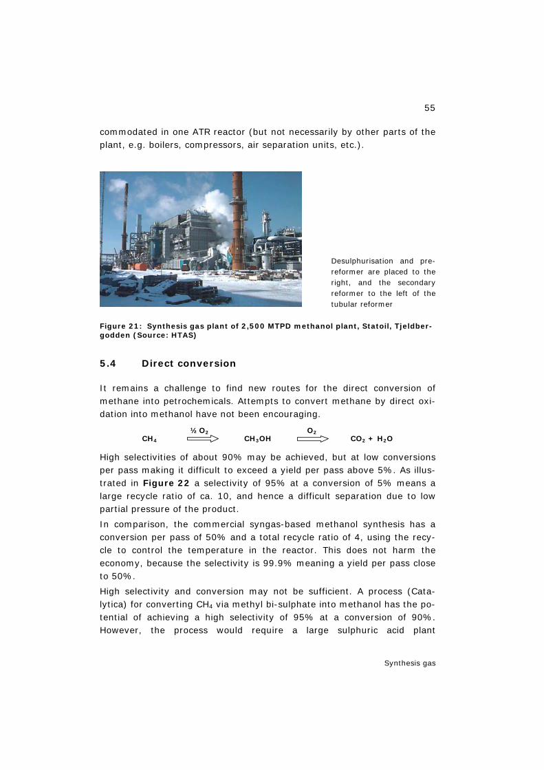
55
Synthesis gas
commodated in one ATR reactor (but not necessarily by other parts of the plant, e.g. boilers, compressors, air separation units, etc.).
Desulphurisation and pre-reformer are placed to the right, and the secondary reformer to the left of the tubular reformer
Figure 21: Synthesis gas plant of 2,500 MTPD methanol plant, Statoil, Tjeldber-godden (Source: HTAS)
5.4 Direct conversion
It remains a challenge to find new routes for the direct conversion of methane into petrochemicals. Attempts to convert methane by direct oxi-dation into methanol have not been encouraging.
CH4 ½O2
CH3OH O2
CO2 + H2O
High selectivities of about 90% may be achieved, but at low conversions per pass making it difficult to exceed a yield per pass above 5%. As illus-trated in Figure 22 a selectivity of 95% at a conversion of 5% means a large recycle ratio of ca. 10, and hence a difficult separation due to low partial pressure of the product.
In comparison, the commercial syngas-based methanol synthesis has a conversion per pass of 50% and a total recycle ratio of 4, using the recy-cle to control the temperature in the reactor. This does not harm the economy, because the selectivity is 99.9% meaning a yield per pass close to 50%.
High selectivity and conversion may not be sufficient. A process (Cata-lytica) for converting CH4 via methyl bi-sulphate into methanol has the po-tential of achieving a high selectivity of 95% at a conversion of 90%. However, the process would require a large sulphuric acid plant
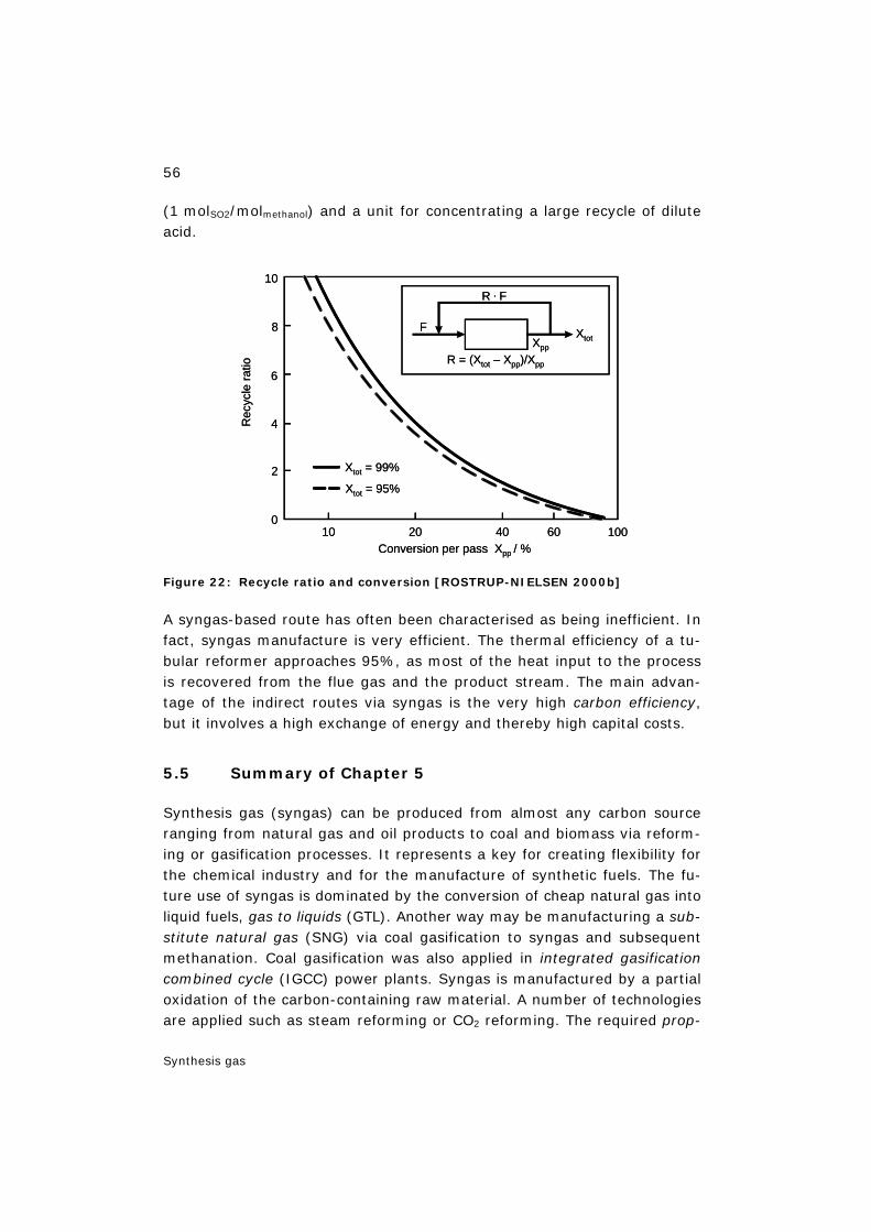
56
Synthesis gas
(1 molSO2/molmethanol) and a unit for concentrating a large recycle of dilute acid.
Figure 22: Recycle ratio and conversion [ROSTRUP-NIELSEN 2000b]
A syngas-based route has often been characterised as being inefficient. In fact, syngas manufacture is very efficient. The thermal efficiency of a tu-bular reformer approaches 95%, as most of the heat input to the process is recovered from the flue gas and the product stream. The main advan-tage of the indirect routes via syngas is the very high carbon efficiency, but it involves a high exchange of energy and thereby high capital costs.
5.5 Summary of Chapter 5
Synthesis gas (syngas) can be produced from almost any carbon source ranging from natural gas and oil products to coal and biomass via reform-ing or gasification processes. It represents a key for creating flexibility for the chemical industry and for the manufacture of synthetic fuels. The fu-ture use of syngas is dominated by the conversion of cheap natural gas into liquid fuels, gas to liquids (GTL). Another way may be manufacturing a sub-stitute natural gas (SNG) via coal gasification to syngas and subsequent methanation. Coal gasification was also applied in integrated gasification combined cycle (IGCC) power plants. Syngas is manufactured by a partial oxidation of the carbon-containing raw material. A number of technologies are applied such as steam reforming or CO2 reforming. The required prop-
Conversion per pass Xpp / %
Rec
ycle
ratio
Xtot = 99%
Xtot = 95%
10
8
6
4
2
020 40 60 10010
Xtot
R . F
F Xpp
R = (Xtot – Xpp)/Xpp
Conversion per pass Xpp / %
Rec
ycle
ratio
Xtot = 99%
Xtot = 95%
10
8
6
4
2
020 40 60 10010
Xtot
R . F
F Xpp
R = (Xtot – Xpp)/Xpp
57
Synthesis gas
erties of the syngas are different for the different syntheses. This means that the synthesis gas ideally has the same stoichiometry as the final product. The synthesis gas for methanol should ideally have a module M which should be close to 2. The choice of technology for the manufacture of synthesis gas depends on the scale of operation. Large capacities of methanol products can be accommodated in one ATR reactor. The main advantage of the indirect routes for methanol production via syngas is the very high carbon efficiency, but it involves a high exchange of energy and thereby high capital costs.
58
Process engineering of methanol synthesis
6 Process engineering of methanol synthesis
6.1 Methanol production technology
All commercially used methanol technologies call for three process units and a utility section as listed below:
– synthesis gas preparation (reforming),
– methanol synthesis,
– methanol purification,
– utilities.
In the synthesis gas preparation section, the hydrocarbon feedstock is pu-rified of for instance sulphur before being converted into synthesis gas at high temperature and subsequently compressed to synthesis pressure. Several reforming technologies are available for gas conversion, e.g.:
− one-step reforming with a tubular reformer,
– two-step reforming,
– autothermal reforming (ATR).
In the methanol synthesis section, the synthesis gas is converted to raw methanol, which contains water and minor amounts of by-products. The straight-tubed boiling water reactor (BWR) is often used being the most efficient reactor type. For large capacities more than one reactor is re-quired and economy of scale may be lost. In this case three adiabatic methanol reactors in series with indirect cooling between the reactors may be attractive.
Water and by-products are removed in the methanol distillation section. The conventional layout is with a two-column system (stabiliser for dis-solved gases and light by-products and concentration column separating methanol and water). The Topsøe system features a split concentration column and an optional ethanol column. The first column operates at higher pressure. This allows the overhead condenser duty to be reused as reboiler duty for the second column – leading to a saving in overall energy consumption.
The utility section comprises water treatment, cooling water system, aux-iliary boiler, power production, and other installations as required for the proper operation of the plant.
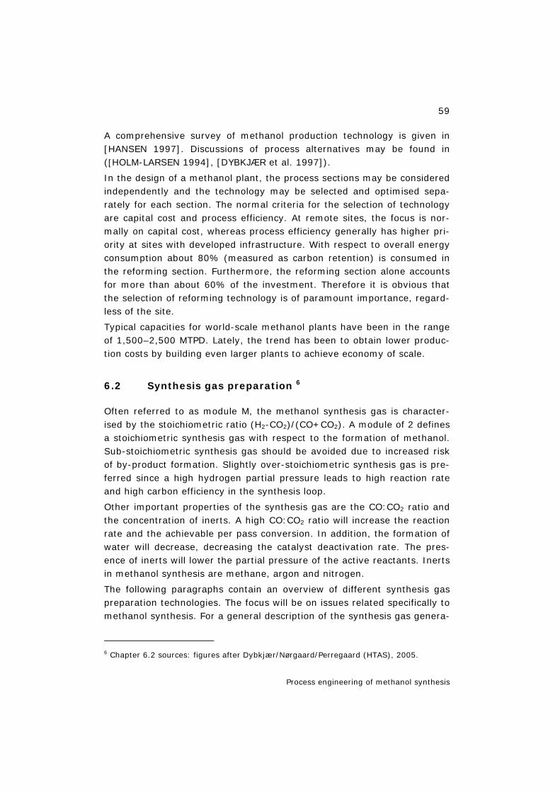
59
Process engineering of methanol synthesis
A comprehensive survey of methanol production technology is given in [HANSEN 1997]. Discussions of process alternatives may be found in ([HOLM-LARSEN 1994], [DYBKJÆR et al. 1997]).
In the design of a methanol plant, the process sections may be considered independently and the technology may be selected and optimised sepa-rately for each section. The normal criteria for the selection of technology are capital cost and process efficiency. At remote sites, the focus is nor-mally on capital cost, whereas process efficiency generally has higher pri-ority at sites with developed infrastructure. With respect to overall energy consumption about 80% (measured as carbon retention) is consumed in the reforming section. Furthermore, the reforming section alone accounts for more than about 60% of the investment. Therefore it is obvious that the selection of reforming technology is of paramount importance, regard-less of the site.
Typical capacities for world-scale methanol plants have been in the range of 1,500–2,500 MTPD. Lately, the trend has been to obtain lower produc-tion costs by building even larger plants to achieve economy of scale.
6.2 Synthesis gas preparation 6
Often referred to as module M, the methanol synthesis gas is character-ised by the stoichiometric ratio (H2-CO2)/(CO+CO2). A module of 2 defines a stoichiometric synthesis gas with respect to the formation of methanol. Sub-stoichiometric synthesis gas should be avoided due to increased risk of by-product formation. Slightly over-stoichiometric synthesis gas is pre-ferred since a high hydrogen partial pressure leads to high reaction rate and high carbon efficiency in the synthesis loop.
Other important properties of the synthesis gas are the CO:CO2 ratio and the concentration of inerts. A high CO:CO2 ratio will increase the reaction rate and the achievable per pass conversion. In addition, the formation of water will decrease, decreasing the catalyst deactivation rate. The pres-ence of inerts will lower the partial pressure of the active reactants. Inerts in methanol synthesis are methane, argon and nitrogen.
The following paragraphs contain an overview of different synthesis gas preparation technologies. The focus will be on issues related specifically to methanol synthesis. For a general description of the synthesis gas genera-
6 Chapter 6.2 sources: figures after Dybkjær/Nørgaard/Perregaard (HTAS), 2005.
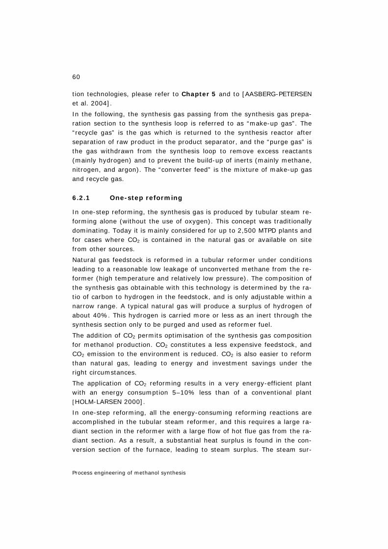
60
Process engineering of methanol synthesis
tion technologies, please refer to Chapter 5 and to [AASBERG-PETERSEN et al. 2004].
In the following, the synthesis gas passing from the synthesis gas prepa-ration section to the synthesis loop is referred to as “make-up gas”. The “recycle gas” is the gas which is returned to the synthesis reactor after separation of raw product in the product separator, and the “purge gas” is the gas withdrawn from the synthesis loop to remove excess reactants (mainly hydrogen) and to prevent the build-up of inerts (mainly methane, nitrogen, and argon). The “converter feed” is the mixture of make-up gas and recycle gas.
6.2.1 One-step reforming
In one-step reforming, the synthesis gas is produced by tubular steam re-forming alone (without the use of oxygen). This concept was traditionally dominating. Today it is mainly considered for up to 2,500 MTPD plants and for cases where CO2 is contained in the natural gas or available on site from other sources.
Natural gas feedstock is reformed in a tubular reformer under conditions leading to a reasonable low leakage of unconverted methane from the re-former (high temperature and relatively low pressure). The composition of the synthesis gas obtainable with this technology is determined by the ra-tio of carbon to hydrogen in the feedstock, and is only adjustable within a narrow range. A typical natural gas will produce a surplus of hydrogen of about 40%. This hydrogen is carried more or less as an inert through the synthesis section only to be purged and used as reformer fuel.
The addition of CO2 permits optimisation of the synthesis gas composition for methanol production. CO2 constitutes a less expensive feedstock, and CO2 emission to the environment is reduced. CO2 is also easier to reform than natural gas, leading to energy and investment savings under the right circumstances.
The application of CO2 reforming results in a very energy-efficient plant with an energy consumption 5–10% less than of a conventional plant [HOLM-LARSEN 2000].
In one-step reforming, all the energy-consuming reforming reactions are accomplished in the tubular steam reformer, and this requires a large ra-diant section in the reformer with a large flow of hot flue gas from the ra-diant section. As a result, a substantial heat surplus is found in the con-version section of the furnace, leading to steam surplus. The steam sur-
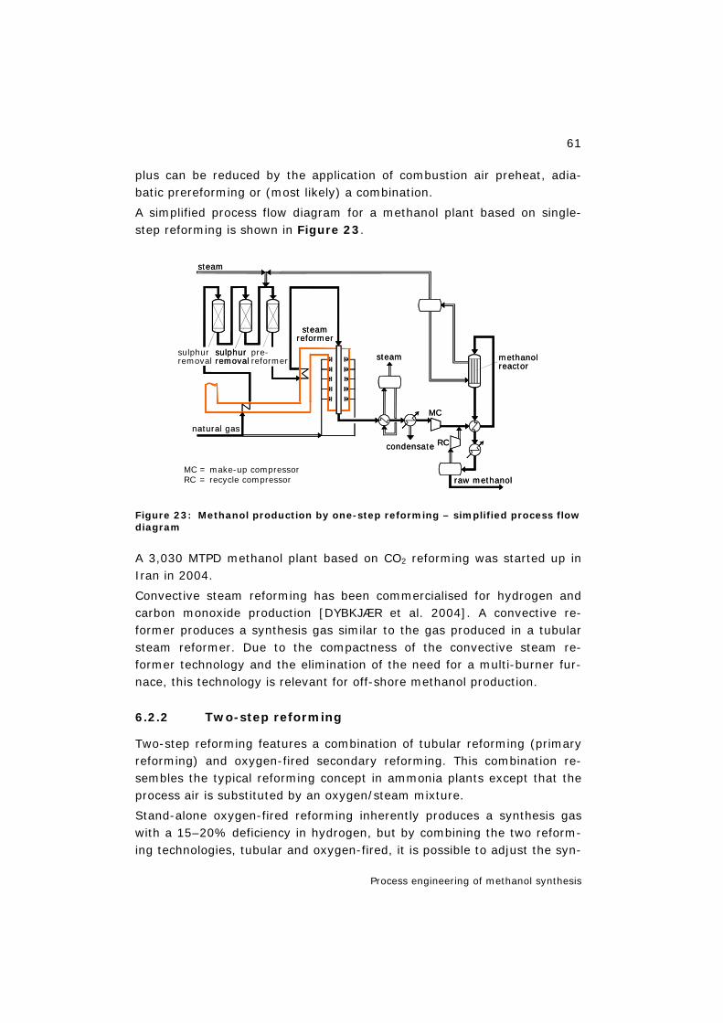
61
Process engineering of methanol synthesis
plus can be reduced by the application of combustion air preheat, adia-batic prereforming or (most likely) a combination.
A simplified process flow diagram for a methanol plant based on single-step reforming is shown in Figure 23.
Figure 23: Methanol production by one-step reforming – simplified process flow diagram
A 3,030 MTPD methanol plant based on CO2 reforming was started up in Iran in 2004.
Convective steam reforming has been commercialised for hydrogen and carbon monoxide production [DYBKJÆR et al. 2004]. A convective re-former produces a synthesis gas similar to the gas produced in a tubular steam reformer. Due to the compactness of the convective steam re-former technology and the elimination of the need for a multi-burner fur-nace, this technology is relevant for off-shore methanol production.
6.2.2 Two-step reforming
Two-step reforming features a combination of tubular reforming (primary reforming) and oxygen-fired secondary reforming. This combination re-sembles the typical reforming concept in ammonia plants except that the process air is substituted by an oxygen/steam mixture.
Stand-alone oxygen-fired reforming inherently produces a synthesis gas with a 15–20% deficiency in hydrogen, but by combining the two reform-ing technologies, tubular and oxygen-fired, it is possible to adjust the syn-
steam
steam
pre-reformer
sulphurremoval
sulphurremoval
steamreformer
methanolreactor
raw methanol
condensate
natural gas
MC
RC
MC = make-up compressorRC = recycle compressor
steam
steam
pre-reformer
sulphurremoval
sulphurremoval
steamreformer
methanolreactor
raw methanol
condensate
natural gas
MC
RC
MC = make-up compressorRC = recycle compressor
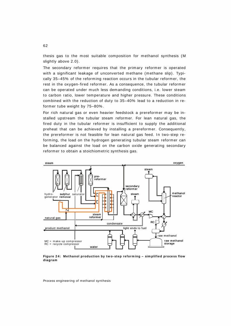
62
Process engineering of methanol synthesis
thesis gas to the most suitable composition for methanol synthesis (M slightly above 2.0).
The secondary reformer requires that the primary reformer is operated with a significant leakage of unconverted methane (methane slip). Typi-cally 35–45% of the reforming reaction occurs in the tubular reformer, the rest in the oxygen-fired reformer. As a consequence, the tubular reformer can be operated under much less demanding conditions, i.e. lower steam to carbon ratio, lower temperature and higher pressure. These conditions combined with the reduction of duty to 35–40% lead to a reduction in re-former tube weight by 75–80%.
For rich natural gas or even heavier feedstock a prereformer may be in-stalled upstream the tubular steam reformer. For lean natural gas, the fired duty in the tubular reformer is insufficient to supply the additional preheat that can be achieved by installing a prereformer. Consequently, the prereformer is not feasible for lean natural gas feed. In two-step re-forming, the load on the hydrogen generating tubular steam reformer can be balanced against the load on the carbon oxide generating secondary reformer to obtain a stoichiometric synthesis gas.
Figure 24: Methanol production by two-step reforming – simplified process flow diagram
steam
natural gas
water
condensate
steam
steam
light ends to fuel
raw methanol
raw methanolstorage
secondaryreformer
methanolreactor
MCsteam
reformer
product methanol
oxygen
saturatorsulphurremoval
pre-reformer
hydro-generator
RC
MC = make-up compressorRC = recycle compressor
steam
natural gas
water
condensate
steam
steam
light ends to fuel
raw methanol
raw methanolstorage
secondaryreformer
methanolreactor
MCsteam
reformer
product methanol
oxygen
saturatorsulphurremoval
pre-reformer
hydro-generator
RC
MC = make-up compressorRC = recycle compressor
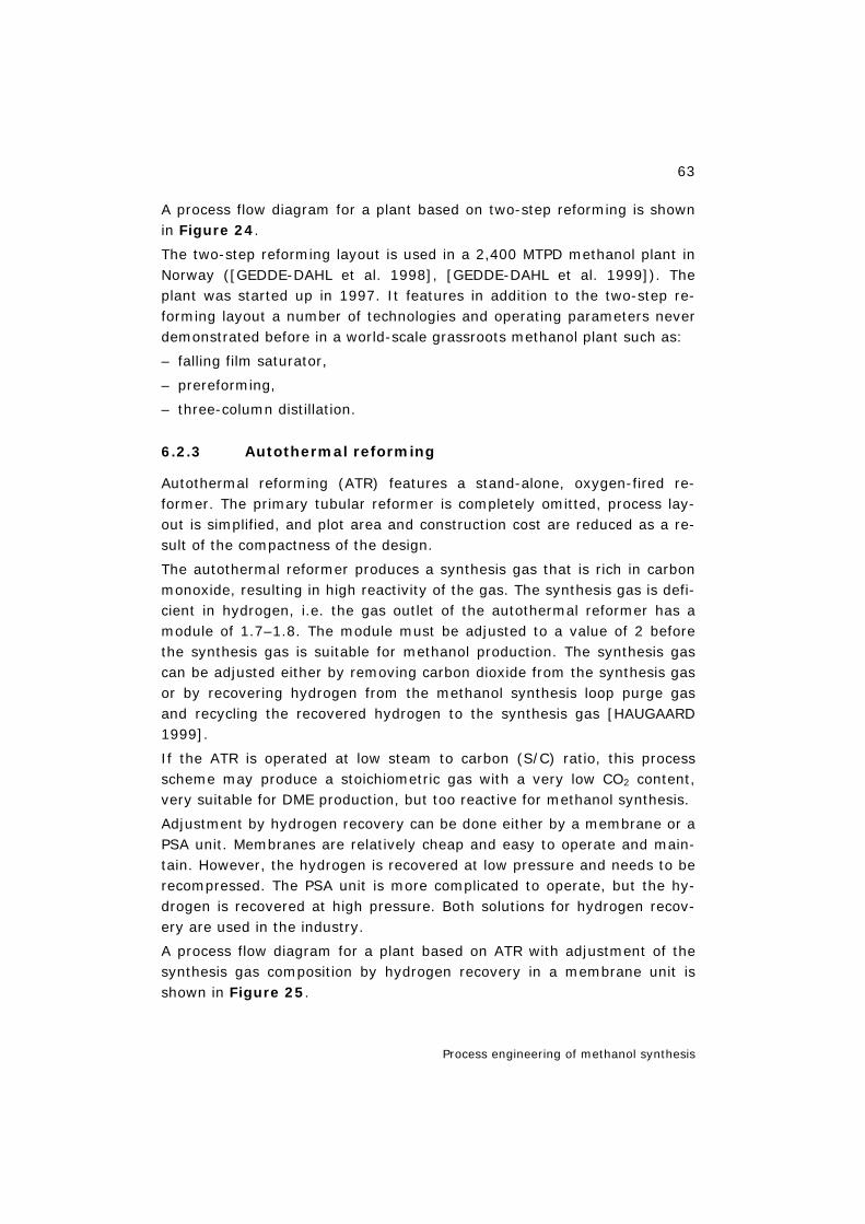
63
Process engineering of methanol synthesis
A process flow diagram for a plant based on two-step reforming is shown in Figure 24.
The two-step reforming layout is used in a 2,400 MTPD methanol plant in Norway ([GEDDE-DAHL et al. 1998], [GEDDE-DAHL et al. 1999]). The plant was started up in 1997. It features in addition to the two-step re-forming layout a number of technologies and operating parameters never demonstrated before in a world-scale grassroots methanol plant such as:
– falling film saturator,
– prereforming,
– three-column distillation.
6.2.3 Autothermal reforming
Autothermal reforming (ATR) features a stand-alone, oxygen-fired re-former. The primary tubular reformer is completely omitted, process lay-out is simplified, and plot area and construction cost are reduced as a re-sult of the compactness of the design.
The autothermal reformer produces a synthesis gas that is rich in carbon monoxide, resulting in high reactivity of the gas. The synthesis gas is defi-cient in hydrogen, i.e. the gas outlet of the autothermal reformer has a module of 1.7–1.8. The module must be adjusted to a value of 2 before the synthesis gas is suitable for methanol production. The synthesis gas can be adjusted either by removing carbon dioxide from the synthesis gas or by recovering hydrogen from the methanol synthesis loop purge gas and recycling the recovered hydrogen to the synthesis gas [HAUGAARD 1999].
If the ATR is operated at low steam to carbon (S/C) ratio, this process scheme may produce a stoichiometric gas with a very low CO2 content, very suitable for DME production, but too reactive for methanol synthesis.
Adjustment by hydrogen recovery can be done either by a membrane or a PSA unit. Membranes are relatively cheap and easy to operate and main-tain. However, the hydrogen is recovered at low pressure and needs to be recompressed. The PSA unit is more complicated to operate, but the hy-drogen is recovered at high pressure. Both solutions for hydrogen recov-ery are used in the industry.
A process flow diagram for a plant based on ATR with adjustment of the synthesis gas composition by hydrogen recovery in a membrane unit is shown in Figure 25.

64
Process engineering of methanol synthesis
Figure 25: Methanol production by ATR at low S/C ratio. Adjustment of synthe-sis gas composition by hydrogen recovery and recycling. Simplified flow dia-gram.
As shown in Figure 25, a prereformer is normally installed upstream the ATR to reduce oxygen consumption and increase the module, thereby re-ducing the amount of recovered and recycled hydrogen.
6.2.4 Gas-heated reforming
To overcome the problems associated with the hydrogen-deficient synthe-sis gas produced in the autothermal reformer, a gas-heated reformer (HTER, Haldor Topsøe Exchanger Reformer, or similar designs) may be in-stalled in parallel (-p) or series (-s) with the autothermal reformer. The concepts are illustrated in Figure 26 [BAKKERUD et al. 2004].
The gas-heated reformer will introduce a degree of steam reforming to the process hereby generating more hydrogen. In the extreme, the process is changed to a concept equivalent to two-step reforming, but with the heat for the steam reforming supplied by heat exchange with the hot gas from the ATR.
Gas-heated reforming holds the potential to increase the efficiency of the autothermal process without compromising its ability to produce a highly reactive synthesis gas at low steam to carbon ratio and high single-line capacity.
oxygen/steam
natural gas
water condensate
steam
rawmethanol
offgas
purgegas
hydro-generator
sulphurremoval
pre-reformer
autothermalreformer methanol
reactor
MC
hydrogenrecovery
saturator
steam
MC = make-up compressorRC = recycle compressor
RC
oxygen/steam
natural gas
water condensate
steam
rawmethanol
offgas
purgegas
hydro-generator
sulphurremoval
pre-reformer
autothermalreformer methanol
reactor
MC
hydrogenrecovery
saturator
steam
MC = make-up compressorRC = recycle compressor
RC
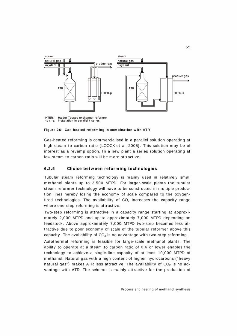
65
Process engineering of methanol synthesis
Figure 26: Gas-heated reforming in combination with ATR
Gas-heated reforming is commercialised in a parallel solution operating at high steam to carbon ratio [LOOCK et al. 2005]. This solution may be of interest as a revamp option. In a new plant a series solution operating at low steam to carbon ratio will be more attractive.
6.2.5 Choice between reforming technologies
Tubular steam reforming technology is mainly used in relatively small methanol plants up to 2,500 MTPD. For larger-scale plants the tubular steam reformer technology will have to be constructed in multiple produc-tion lines hereby losing the economy of scale compared to the oxygen-fired technologies. The availability of CO2 increases the capacity range where one-step reforming is attractive.
Two-step reforming is attractive in a capacity range starting at approxi-mately 2,000 MTPD and up to approximately 7,000 MTPD depending on feedstock. Above approximately 7,000 MTPD two-step becomes less at-tractive due to poor economy of scale of the tubular reformer above this capacity. The availability of CO2 is no advantage with two-step reforming.
Autothermal reforming is feasible for large-scale methanol plants. The ability to operate at a steam to carbon ratio of 0.6 or lower enables the technology to achieve a single-line capacity of at least 10,000 MTPD of methanol. Natural gas with a high content of higher hydrocarbons (“heavy natural gas”) makes ATR less attractive. The availability of CO2 is no ad-vantage with ATR. The scheme is mainly attractive for the production of
product gas
HTER-p
ATR
product gasnatural gas
steam
oxydant
ATR
HTER-s
steam
natural gas
oxydant
HTER: Haldor Topsøe exchanger reformer-p / -s: installation in parallel / series
product gas
HTER-p
ATR
product gasnatural gas
steam
oxydant
ATR
HTER-s
steam
natural gas
oxydant
HTER: Haldor Topsøe exchanger reformer-p / -s: installation in parallel / series
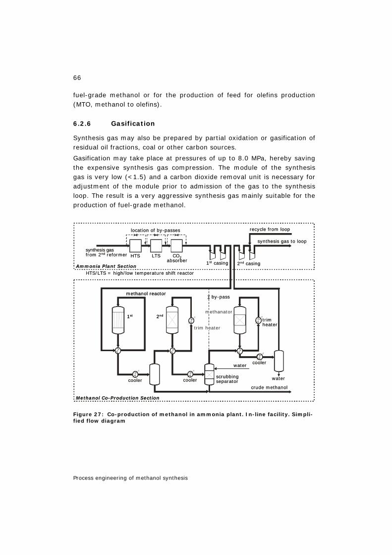
66
Process engineering of methanol synthesis
fuel-grade methanol or for the production of feed for olefins production (MTO, methanol to olefins).
6.2.6 Gasification
Synthesis gas may also be prepared by partial oxidation or gasification of residual oil fractions, coal or other carbon sources.
Gasification may take place at pressures of up to 8.0 MPa, hereby saving the expensive synthesis gas compression. The module of the synthesis gas is very low (<1.5) and a carbon dioxide removal unit is necessary for adjustment of the module prior to admission of the gas to the synthesis loop. The result is a very aggressive synthesis gas mainly suitable for the production of fuel-grade methanol.
Figure 27: Co-production of methanol in ammonia plant. In-line facility. Simpli-fied flow diagram
HTS
location of by-passes
LTS
1st casing 2nd casing
cooler cooler
coolerwater
water
crude methanol
scrubbingseparator
recycle from loop
synthesis gas to loop
CO2absorber
by-pass
trimheater
methanator
Ammonia Plant Section
Methanol Co-Production Section
trim heater
methanol reactor
1st 2nd
synthesis gasfrom 2nd reformer
HTS/LTS = high/low temperature shift reactor
67
Process engineering of methanol synthesis
6.2.7 Co-production of methanol in ammonia plants
In certain cases it is interesting for ammonia plant owners to convert part of their capacity to methanol production. Besides adding flexibility, the co-production unit is compact, fast to install and low in investment. Several options are available for the integration of methanol production in existing or new ammonia plants:
– purge-gas-based facility; utilising hydrogen from the ammonia loop purge gas and carbon dioxide from the front-end,
– side stream facility; where the methanol reactor operates in parallel with the ammonia plant shift reactors,
– in-line facility; using the ammonia make-up gas compressor to obtain the desired methanol reactor pressure.
An in-line facility has been implemented at the ammonia/methanol co-production plant, Malaysia [HOLM-LARSEN 2000]. A simplified process flow diagram is shown in Figure 27.
6.3 Methanol synthesis 7
In methanol synthesis, conversion of synthesis gas into raw methanol takes place. Raw methanol is a mixture of methanol, water and by-products, predominantly higher alcohols, ethers, acetone and methyl-ethyl-ketone.
6.3.1 Thermodynamics
The conversion in methanol synthesis can be described by the following reactions:
CO2 + 3 H2 CH3OH + H2O (-∆H298K, 50bar = 40.9 kJ/mol) eq. 6.1
CO + 2 H2 CH3OH (-∆H298K, 50bar = 90.7 kJ/mol) eq. 6.2
CO2 + H2 CO + H2O (-∆H298K, 50bar = 49.8 kJ/mol) eq. 6.3
A combination of either equations 6.1 and 6.3 or equations 6.2 and 6.3 completely describes the system from a thermodynamic point of view, whereas all three equations are generally considered when a kinetic de-scription of the synthesis is required.
7 Chapter 6.3 sources: figures after Dybkjær/Nørgaard/Perregaard (HTAS), 2005.
68
Process engineering of methanol synthesis
It can be seen from equations 6.1, 6.2 and 6.3 that the methanol syn-thesis is exothermic and involves a decrease in the number of moles. Thus, according to Le Chatelier’s principle, maximum conversion is ob-tained at low temperature and high pressure. A challenge in the design of a methanol synthesis is to remove the heat of reaction efficiently and eco-nomically – i.e. at high temperature – but at the same time equilibrating the synthesis reaction at low temperature hereby ensuring a high per pass conversion.
Inerts like CH4, N2 or Ar lower the possible conversion. It is noted that even in a stoichiometric synthesis gas free from inerts, maximum conver-sion will decrease with increasing CO2 content. Under typical synthesis conditions (7.5 MPa, 225 °C) the carbon conversion (conversion of carbon oxides to methanol) per pass in traditional gas phase reactors can not ex-ceed the thermodynamic limit around 60%.
6.3.2 Catalysts
The first industrial production of methanol was performed at high pressure using catalysts consisting of zinc oxide and chromium oxide. These cata-lysts were very stable towards catalyst poisons such as sulphur and chlo-rine components, which were often present in the synthesis gas at that time.
Developments in gas cleaning technologies allowed the use of the much more active and selective catalyst based on copper and zinc oxide identi-fied by BASF in the 1920s. This resulted in the low-pressure methanol synthesis first used by ICI in the 1960s.
Today, the synthesis of methanol is almost exclusively performed over catalyst based on copper/zinc/alumina.
6.3.3 Reaction mechanism
The reaction mechanism for the low-temperature methanol synthesis catalyst is still debated and controversial. The main points in the debate are whether or not methanol is exclusively produced from CO2 or whether the direct formation of methanol from CO is also possible.
Great efforts have been made to understand the mechanism and an over-whelming amount of information exists in the literature (cf. e.g. [HANSEN 1997]). A key in understanding is the adsorption properties of the differ-ent species as well as the surface components that can be identified. A number of different analytical techniques have been used (IR, DRIFTS,
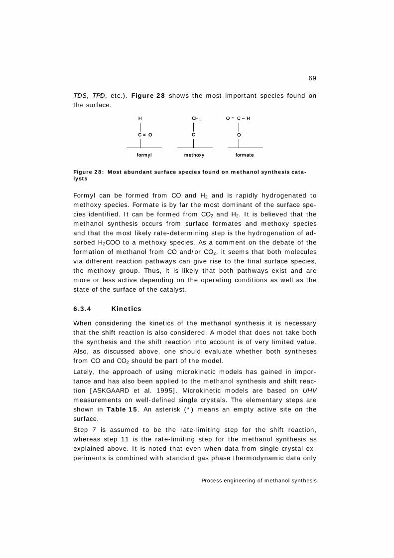
69
Process engineering of methanol synthesis
TDS, TPD, etc.). Figure 28 shows the most important species found on the surface.
Figure 28: Most abundant surface species found on methanol synthesis cata-lysts
Formyl can be formed from CO and H2 and is rapidly hydrogenated to methoxy species. Formate is by far the most dominant of the surface spe-cies identified. It can be formed from CO2 and H2. It is believed that the methanol synthesis occurs from surface formates and methoxy species and that the most likely rate-determining step is the hydrogenation of ad-sorbed H2COO to a methoxy species. As a comment on the debate of the formation of methanol from CO and/or CO2, it seems that both molecules via different reaction pathways can give rise to the final surface species, the methoxy group. Thus, it is likely that both pathways exist and are more or less active depending on the operating conditions as well as the state of the surface of the catalyst.
6.3.4 Kinetics
When considering the kinetics of the methanol synthesis it is necessary that the shift reaction is also considered. A model that does not take both the synthesis and the shift reaction into account is of very limited value. Also, as discussed above, one should evaluate whether both syntheses from CO and CO2 should be part of the model.
Lately, the approach of using microkinetic models has gained in impor-tance and has also been applied to the methanol synthesis and shift reac-tion [ASKGAARD et al. 1995]. Microkinetic models are based on UHV measurements on well-defined single crystals. The elementary steps are shown in Table 15. An asterisk (*) means an empty active site on the surface.
Step 7 is assumed to be the rate-limiting step for the shift reaction, whereas step 11 is the rate-limiting step for the methanol synthesis as explained above. It is noted that even when data from single-crystal ex-periments is combined with standard gas phase thermodynamic data only
C = O
H
O
CH3
O
O = C – H
formyl methoxy formate
C = O
H
O
CH3
O
O = C – H
formyl methoxy formate
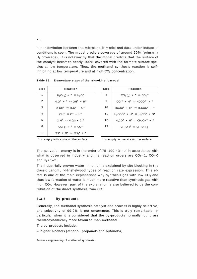
70
Process engineering of methanol synthesis
minor deviation between the microkinetic model and data under industrial conditions is seen. The model predicts coverage of around 50% (primarily H2 coverage). It is noteworthy that the model predicts that the surface of the catalyst becomes nearly 100% covered with the formate surface spe-cies at low temperature. Thus, the methanol synthesis reaction is self-inhibiting at low temperature and at high CO2 concentration.
Table 15: Elementary steps of the microkinetic model
Step Reaction Step Reaction
1 H2O(g) + * H2O* 8 CO2 (g) + * CO2 *
2 H2O* + * OH* + H* 9 CO2* + H* HCOO* + *
3 2 OH* H2O* + O* 10 HCOO* + H* H2COO* + *
4 OH* O* + H* 11 H2COO* + H* H3CO* + O*
5 2 H* H2(g) + 2 * 12 H3CO* + H* CH3OH* + *
6 CO(g) + * CO* 13 CH3OH* CH3OH(g)
7 CO* + O* CO2* + *
* = empty active site on the surface * = empty active site on the surface
The activation energy is in the order of 75–100 kJ/mol in accordance with what is observed in industry and the reaction orders are CO2=1, CO≈0 and H2=1–2.
The industrially proven water inhibition is explained by site blocking in the classic Langmuir-Hinshelwood types of reaction rate expression. This ef-fect is one of the main explanations why synthesis gas with low CO2 and thus low formation of water is much more reactive than synthesis gas with high CO2. However, part of the explanation is also believed to be the con-tribution of the direct synthesis from CO.
6.3.5 By-products
Generally, the methanol synthesis catalyst and process is highly selective, and selectivity of 99.9% is not uncommon. This is truly remarkable, in particular when it is considered that the by-products normally found are thermodynamically more favoured than methanol.
The by-products include:
– higher alcohols (ethanol, propanols and butanols),
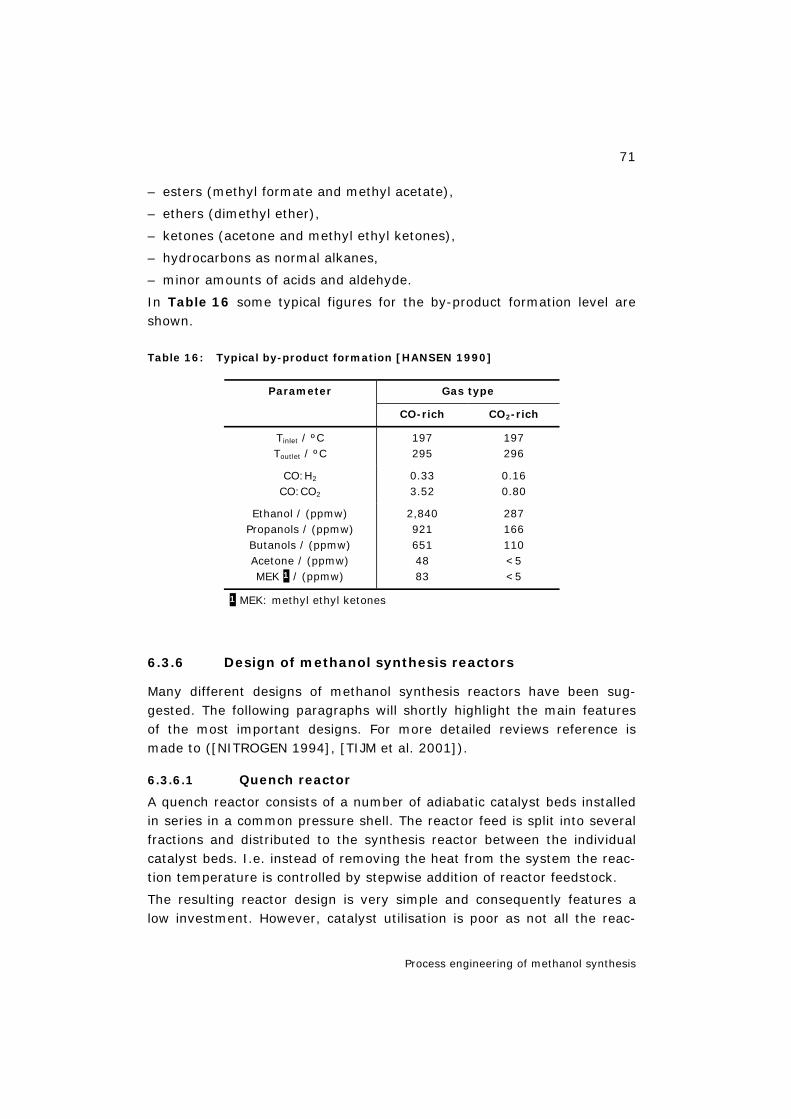
71
Process engineering of methanol synthesis
– esters (methyl formate and methyl acetate),
– ethers (dimethyl ether),
– ketones (acetone and methyl ethyl ketones),
– hydrocarbons as normal alkanes,
– minor amounts of acids and aldehyde.
In Table 16 some typical figures for the by-product formation level are shown.
Table 16: Typical by-product formation [HANSEN 1990]
Gas type Parameter
CO-rich CO2-rich
Tinlet / ºC Toutlet / ºC
197 295
197 296
CO:H2
CO:CO2 0.33 3.52
0.16 0.80
Ethanol / (ppmw) Propanols / (ppmw) Butanols / (ppmw) Acetone / (ppmw) MEK 1 / (ppmw)
2,840 921 651 48 83
287 166 110 <5 <5
1 MEK: methyl ethyl ketones
6.3.6 Design of methanol synthesis reactors
Many different designs of methanol synthesis reactors have been sug-gested. The following paragraphs will shortly highlight the main features of the most important designs. For more detailed reviews reference is made to ([NITROGEN 1994], [TIJM et al. 2001]).
6.3.6.1 Quench reactor
A quench reactor consists of a number of adiabatic catalyst beds installed in series in a common pressure shell. The reactor feed is split into several fractions and distributed to the synthesis reactor between the individual catalyst beds. I.e. instead of removing the heat from the system the reac-tion temperature is controlled by stepwise addition of reactor feedstock.
The resulting reactor design is very simple and consequently features a low investment. However, catalyst utilisation is poor as not all the reac-
72
Process engineering of methanol synthesis
tants pass through the entire catalyst volume installed. The adiabatic na-ture of the design implies that the equilibrium temperature is high result-ing in a low per pass conversion. The lack of internal or inter-stage cooling results in an inefficient heat recovery. Most of the generated heat must be removed by air or water cooling.
6.3.6.2 Adiabatic reactor
An adiabatic reactor system normally consists of a number of fixed-bed synthesis reactors placed in series. Heat is removed downstream each re-actor by the generation of medium-pressure steam.
An adiabatic reactor system features a good economy of scale. Mechanical simplicity gives a low investment cost. The fixed-bed reactor design can be scaled up to single-line capacities of 10,000 MTPD. However, due the adiabatic nature of the system the equilibrium temperature is high result-ing in a low per pass conversion and high recycle ratio. The high recycle ratio dilutes the reactants resulting in high catalyst volumes. Thus, the ef-ficiency of the adiabatic reactor system is low compared to systems with internal cooling. Reference is made to [HOLM-LARSEN 1994].
6.3.6.3 Boiling water reactor
The boiling water reactor is in principle a shell and tube heat exchanger with catalyst on the tube side. Cooling of the reactor is provided by circu-lating boiling water on the shell side. By controlling the pressure of the circulating boiling water the reaction temperature may be controlled and optimised easily.
The approximately isothermal nature of the reactor design gives a high conversion compared to the amount of catalyst installed. However, to en-sure a proper reaction rate the reactor will operate at intermediate tem-peratures – say between 240ºC and 260ºC – and consequently the recycle ratio may still be significant.
Complex mechanical design results in relatively high investment cost. Moreover, the tube sheet constrains the maximum size of the synthesis reactor. Thus, for large-scale plants several boiling water reactors must be installed in parallel, thus eliminating the economy of scale.
6.3.6.4 Gas-cooled reactor
The gas-cooled reactor design is often designed into a feed/effluent heat exchanger around a boiling water reactor. I.e. on one side of the heat ex-changer the boiling water reactor feed is preheated while on the other side of the heat exchanger catalyst is installed and the boiling water reactor ef-
73
Process engineering of methanol synthesis
fluent is brought to equilibrium at a lower temperature. With a gas-cooled reactor in series with a boiling water reactor very high per pass conver-sions may be achieved. However, due to the low temperature in the gas-cooled reactor the reaction rate is low and the amount of catalyst needed to make the reaction occur is correspondingly high.
6.3.6.5 Integrated gas-cooled reactor
An integrated design of the boiling water reactor and the gas-cooled reac-tor is also available. The design is similar to the boiling water reactor ex-cept that feed gas is heated in centre tubes placed in the catalyst tube in the boiling water reactor. In terms of efficiency, the design is an interme-diate between the pure boiling water reactor design and the design with an external gas-cooled reactor. However, the integrated gas-cooled reac-tor is mechanically complex and consequently it features a high invest-ment cost.
6.3.6.6 Radial flow reactor
As in a boiling water reactor the radial flow reactor is cooled by circulating boiling water. However, in the radial flow reactor the catalyst is installed on the shell side and the boiling water flows on the tube side. The synthe-sis gas feed flow is distributed along the shell of the reactor and flows to-wards the centre where it is collected in a centre tube.
The benefit of a radial flow reactor is that higher single-line capacities may be achieved as the capacity can be increased by increasing the height of the reactor. I.e. the tube sheet diameter is no longer the constraint. From an efficiency point of view the radial flow reactor is an intermediate be-tween the boiling water reactor and an adiabatic reactor.
6.3.6.7 Slurry phase reactor
The only alternative to the fixed-bed reactor type, which has been tested on a larger scale, is the slurry phase system, where finely divided metha-nol synthesis catalyst is suspended in inert oil [ALLAM et al. 1998]. The heat of reaction may either be removed in an external heat exchanger or by inserting a coil into the slurry reactor.
The slurry reactor features good temperature control. The main disadvan-tages are that a slip of the inert oil increases the cost of chemicals. In ad-dition the larger reactor volume as the maximum catalyst loading is 50wt% slurry concentration and a high degree of back mixing, which low-ers the achievable per pass conversion.

74
Process engineering of methanol synthesis
6.3.7 Condensing methanol
The major drawback of the conventional synthesis of methanol is the need for recycling in order to achieve a high conversion of the make-up gas. Recycling is dictated by the unfavourable gas phase thermodynamics at the temperature required by the methanol catalysts available. However, the limitations dictated by gas phase equilibrium may be overcome by condensing the methanol produced on the catalyst inside the reactor [HANSEN 1990].
The concept of condensing methanol has been demonstrated on a pilot scale and plans for the demonstration of the integrated technology based on ATR and condensing methanol have been announced [SØRENSEN et al. 2004].
6.4 Methanol purification 8
Methanol purification consists of a number of distillation columns. The number of columns will depend on the desired quality of the methanol product and the requirements for energy integration at the specific prod-uct facility.
6.4.1 Low-grade methanol
Low-grade methanol has two main applications: fuel and feedstock for a downstream olefin plant. No official or internationally recognised specifica-tion exists for low-grade methanol. Thus, the quality of low-grade metha-nol can be anything between stabilised raw methanol and methanol from which water has been partially removed.
In case the product is stabilised raw methanol, the purification process simply consists of a stabiliser column in which dissolved gases and very light by-products are stripped off.
In case the water content of the raw methanol is too high, a concentration column must be added to the purification system. In the concentration column the methanol will be evaporated in order to withdraw the desired amount of water. All heavy by-products normally remain with the metha-nol product.
8 Chapter 6.4 sources: figures after Dybkjær/Nørgaard/Perregaard (HTAS), 2005.

75
Process engineering of methanol synthesis
6.4.2 High-grade methanol
A chemical-grade AA methanol is >99.85wt% methanol. The main part of the methanol produced today is of grade AA or similar quality. The grade AA quality can be achieved in either a two-column or a three-column dis-tillation layout.
6.4.2.1 Two-column distillation
A two-column distillation layout consists of a stabiliser and a concentration column. In the stabiliser column dissolved gases and very light by-products are stripped off. In the concentration column the stabilised methanol is separated into four streams: from the bottom of the column water is withdrawn, from a centre tray higher by-products are withdrawn, from the top just under a rectifying section the product methanol is with-drawn and from the top light by-products are purged.
6.4.2.2 Three-column distillation
A three-column distillation layout consists of a stabiliser and two concen-tration columns. One of the two concentration columns operates at slightly elevated pressure. This will enable the use of condensation duty of the high-pressure column as reboiler duty in the low-pressure concentration column. Hereby the separation duty utilised in the distillation section may be reduced by as much as 30% compared with a two-column layout. The layout is shown in Figure 29.
Figure 29: Methanol distillation with two concentration columns – simplified process flow diagram
methanol
excess water
fuel
grade AAmethanol
LP concentration column
process gas
HP concentration columnstabiliser column
methanol
excess water
fuel
grade AAmethanol
LP concentration column
process gas
HP concentration columnstabiliser column

76
Process engineering of methanol synthesis
6.5 Dimethyl ether technologies 9
Dimethyl ether (DME) is the simplest aliphatic ether. It is a colourless gas at ambient conditions and has physical properties similar to LPG.
The total production of DME is in the order of 150,000 MTPY. It is today primarily used as a propellant. A large interest in DME as a clean fuel is giving grounds for optimism with respect to a potential very large growth in the market for DME. A number of applications are under consideration and are briefly listed below:
– LPG substitution,
– diesel fuel,
– fuel in power plants,
– hydrogen carrier,
– chemical intermediate (feed for MTO plants, synthetic gasoline, etc.).
If any of these applications materialise, a growth in DME consumption of many orders of magnitude can be foreseen. In Table 17, the application of DME today is given.
Table 17: Use of DME and market share
Use of DME Market share
Hair spray Spray paints Insecticides Adhesives
Industrial feedstock Miscellaneous
48% 6% 6% 5% 31% 4%
Three routes for the production of DME dominate both the production and the literature on the subject:
– methanol/DME co-production,
– methanol dehydration,
– direct synthesis.
Until the late 1970s DME was obtained as a by-product of the high-temperature methanol technology used thus based on a co-production of methanol and DME. Today, the production is clearly dominated by the
9 Chapter 6.5 sources: figures after Dybkjær/Nørgaard/Perregaard (HTAS), 2005.
77
Process engineering of methanol synthesis
methanol dehydration technology, whereas it is suggested in the open lit-erature that their might be cost benefits by using a direct synthesis from synthesis gas in large-scale plants.
DME is formed via the dehydration reaction of two methanol molecules. I.e. methanol is also a precursor for the formation of DME in the direct synthesis. Consequently, the technology for the production of synthesis gas for DME production is identical to the synthesis gas technology for methanol production.
For the DME synthesis two distinct different designs are available. Either DME may be produced in a dedicated DME synthesis by dehydration of methanol. Upstream the dedicated DME synthesis a dedicated methanol synthesis is installed. Alternatively, the DME may be produced in a com-bined synthesis unit, in which the formation of methanol and DME takes place as parallel reaction in the same synthesis loop.
6.5.1 Methanol dehydration
The feedstock for a methanol dehydration unit is raw methanol as pro-duced in a conventional methanol synthesis loop.
The methanol feed is evaporated and routed to the DME synthesis reactor, where the methanol is converted into DME. Per pass efficiencies of more than 80% may be achieved.
The DME synthesis reactor may either be an adiabatic fixed-bed reactor or a tube and shell type reactor where the heat of reaction may be removed by circulating oil. The DME synthesis typically operates at pressures rang-ing from 15–20 barg.
DME is separated in a distillation column. The bottom product consists of water formed in the dehydration reaction and unreacted methanol. Water can be separated from methanol in a waste water column, and unreacted methanol may be recycled to the synthesis reactor.
6.5.2 Combined synthesis
In a combined synthesis the synthesis of methanol and DME is performed in one synthesis loop ([DYBKJÆR et al. 1997], [SØRENSEN et al. 2003]). The feedstock to the combined synthesis loop is synthesis gas identical to the methanol synthesis gas as described above. The combined synthesis loop features a dual-function catalyst with activity for both the synthesis of methanol and the synthesis of DME. Thus, the product from the synthe-sis loop is a mixture of DME, methanol and water corresponding to the
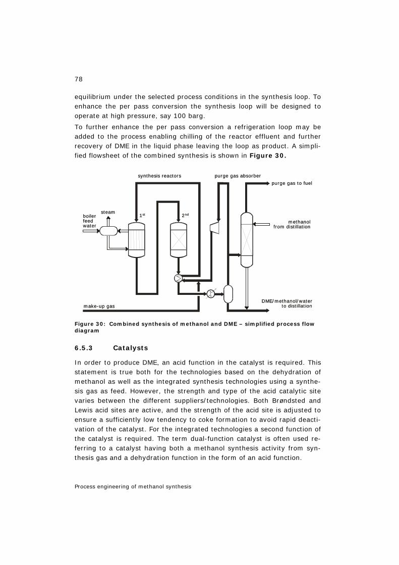
78
Process engineering of methanol synthesis
equilibrium under the selected process conditions in the synthesis loop. To enhance the per pass conversion the synthesis loop will be designed to operate at high pressure, say 100 barg.
To further enhance the per pass conversion a refrigeration loop may be added to the process enabling chilling of the reactor effluent and further recovery of DME in the liquid phase leaving the loop as product. A simpli-fied flowsheet of the combined synthesis is shown in Figure 30.
Figure 30: Combined synthesis of methanol and DME – simplified process flow diagram
6.5.3 Catalysts
In order to produce DME, an acid function in the catalyst is required. This statement is true both for the technologies based on the dehydration of methanol as well as the integrated synthesis technologies using a synthe-sis gas as feed. However, the strength and type of the acid catalytic site varies between the different suppliers/technologies. Both Brøndsted and Lewis acid sites are active, and the strength of the acid site is adjusted to ensure a sufficiently low tendency to coke formation to avoid rapid deacti-vation of the catalyst. For the integrated technologies a second function of the catalyst is required. The term dual-function catalyst is often used re-ferring to a catalyst having both a methanol synthesis activity from syn-thesis gas and a dehydration function in the form of an acid function.
make-up gas
steam
purge gas to fuel
synthesis reactors
1st 2nd
purge gas absorber
methanolfrom distillation
DME/methanol/waterto distillation
boilerfeedwater
make-up gas
steam
purge gas to fuel
synthesis reactors
1st 2nd
purge gas absorber
methanolfrom distillation
DME/methanol/waterto distillation
boilerfeedwater
79
Process engineering of methanol synthesis
6.5.3.1 Dehydration catalysts
The reaction catalysed by the dehydration catalysts is:
2 CH3OH CH3OCH3 + H2O (-∆H298K = 23.4 kJ/mol) eq. 6.4
Numerous catalysts have been suggested and include (but are not limited to) iron chloride, copper sulphate, aluminium chloride and aluminium phosphates. Industrially, the most important catalyst is based on alumin-ium oxide or aluminium silicates with or without promoters.
The reaction is generally very selective with the formation of only minor amounts of by-products like hydrocarbons. The key point for the catalyst is to have a sufficiently high acidity in order to have a high activity but without having a pronounced function of forming coke on the catalyst sur-face.
The mostly used kinetic models are based on the Langmuir-Hinshelwood mechanism and the rate-limiting step is considered to be the reaction be-tween the two adsorbed methanol molecules.
6.5.3.2 Catalysts used in integrated technologies
Besides the dehydration reaction (eq. 6.4) the following reactions are also catalysed by the catalysts used in the integrated technologies:
CO2 + 3 H2 CH3OH + H2O (-∆H298K, 50bar = 40.9 kJ/mol) eq. 6.1
CO + 2 H2 CH3OH (-∆H298K, 50bar = 90.7 kJ/mol) eq. 6.2
CO2 + H2 CO + H2O (-∆H298K, 50bar = 49.8 kJ/mol) eq. 6.3
The term ‘dual-function catalyst’ is often used. In the gas phase version of the integrated technologies a catalyst based on the traditional methanol synthesis system (Cu/Zn/AL2O3) is combined with an acid function. The acid function can be in the form of promoted alumina or a zeolite-based material. The SAPO type of materials (silicoaluminophosphate catalysts) has also been mentioned in the open literature.
In the slurry bed version of the technology more than one catalyst is often used. In this technology, catalyst powder is suspended in an appropriate fluid. Thus, it is easy to use a physical mixture of different materials. A traditional methanol catalyst powder combined with alumina or aluminium phosphates has been mentioned. A large effort by Air Products aimed at using molecular sieves as the catalyst resulted in the conclusion that it was not possible to find a material with a superior performance compared to the combination mentioned above.
80
Process engineering of methanol synthesis
6.6 Methanol reforming in water gas shift reactors 10
The need for hydrogen will continue to increase especially in the refinery industry as the requirements concerning sulphur and aromatics content become more stringent due to environmental concerns and as the feed-
stocks become heavier (higher content of higher hydrocarbons) [ROSTRUP-NIELSEN 2002b]. Both methanol (MeOH) and dimethyl ether (DME) can be seen as convenient energy carriers as both chemicals can be easily steam reformed to generate hydrogen with a high yield.
A novel concept has been invented where the steam reforming of metha-nol or DME is carried out concurrently with the water gas shift reaction in the existing shift reactors in hydrogen plants. This concept represents an inexpensive and flexible option for debottlenecking hydrogen production capacity in existing hydrogen plants.
6.6.1 Thermodynamics
When using methanol as co-feed to a shift reactor it is instructive to con-sider the thermodynamics of the two reactions
eq. 6.5
eq. 6.6
The shift reaction is mildly exothermic whereas methanol steam reforming is moderately endothermic. It can be seen that at 280 ºC
eq. 6.7
It is thus possible to reform 3 moles of methanol per every 5 moles of CO shifted under isothermal conditions by using the reaction heat of the shift reaction to drive the methanol reforming reaction. This means that an ad-ditional 9 moles of hydrogen is generated per 5 moles of CO converted in the shift reactor.
The principle can also be used if DME is introduced to the shift reactor be-cause DME can be converted to methanol according to:
eq. 6.8
10 Chapter 6.6 sources: figures after [HANSEN et al. 2005].
shift2 2 2 280 CCO H O CO H 37.83 kJ/molΔH °+ = + =−
MeOH,reform3 2 2 2 280 CCH OH H O CO 3H 63.01 kJ/molΔH °+ = + = −−
MeOH,reform shift280C 280 C5 /3 ( )ΔH ΔH °= × −
DME,hydration3 3 2 3 280 CCH OCH H O 2CH OH 21.71 kJ/molΔH °+ = = −−
81
Process engineering of methanol synthesis
This will require an additional solid acid catalyst function, whereas metha-nol reforming and shift can be performed simply using a modified copper-based catalyst.
6.6.2 The kinetics of methanol reforming in low-temperature water gas shift reactors
The kinetics of the industrial low-temperature water gas shift reaction and methanol synthesis reaction have previously been studied extensively and microkinetic models have been proposed for both reactions ([OVESEN et al. 1996], [OVESEN et al. 1997]). The active site for both reactions has been proposed to be metallic copper. This hypothesis has been substanti-ated by a vast number of in-situ experiments including EXAFS and TEM studies ([CLAUSEN et al. 1991], [HANSEN et al. 2002]). The microkinetic model has been able to describe the reaction rate for the water gas shift reaction measured over the commercial low-temperature catalyst and the reaction rate of methanol synthesis measured over the commercial methanol catalyst. The understanding of the kinetics of methanol reform-ing in low-temperature water gas shift reactors can be based on these models.
A simplified kinetic model can be developed based on the microkinetic model. A simulation with the full microkinetic model shows that the sur-face species present in large amounts under water gas shift conditions are hydrogen and formate. The simplified kinetic model is:
Here P0 is the reference pressure 1 atm. The pre-exponential factors for the rate constant of methanol reforming and water gas shift have been adjusted to fit experimental measured rates of methanol reforming and shift reaction under methanol to shift conditions. The activation barrier for methanol reforming and water-gas shift is taken from the microkinetic model [OVESEN et al. 1997]. In addition, the adsorption constant of hy-drogen and formate is taken from the microkinetic model [OVESEN et al.
( )3 2
2
CH OH H O 2reforming reforming *1.5 0.5
H 0
P Pr = k 1-β θ
P Pi
( )2
2
CO H O 2shift shift *
H 0
P Pr = k 1-β θ
P Pi
2 2 22
0.5 0.5H CO H1
* H HCOO* 1.50 0
P P Pθ 1 K K
P P− ⎞⎛
= + +⎟⎜⎜ ⎟⎝ ⎠
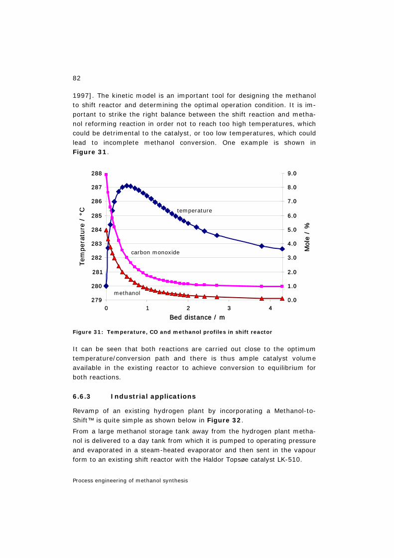
82
Process engineering of methanol synthesis
1997]. The kinetic model is an important tool for designing the methanol to shift reactor and determining the optimal operation condition. It is im-portant to strike the right balance between the shift reaction and metha-nol reforming reaction in order not to reach too high temperatures, which could be detrimental to the catalyst, or too low temperatures, which could lead to incomplete methanol conversion. One example is shown in Figure 31.
Figure 31: Temperature, CO and methanol profiles in shift reactor
It can be seen that both reactions are carried out close to the optimum temperature/conversion path and there is thus ample catalyst volume available in the existing reactor to achieve conversion to equilibrium for both reactions.
6.6.3 Industrial applications
Revamp of an existing hydrogen plant by incorporating a Methanol-to-Shift™ is quite simple as shown below in Figure 32.
From a large methanol storage tank away from the hydrogen plant metha-nol is delivered to a day tank from which it is pumped to operating pressure and evaporated in a steam-heated evaporator and then sent in the vapour form to an existing shift reactor with the Haldor Topsøe catalyst LK-510.
279
280
281
282
283
284
285
286
287
288
0 1 2 3 4
Bed distance / m
0.0
1.0
2.0
3.0
4.0
5.0
6.0
7.0
8.0
9.0
temperature
carbon monoxide
methanol
Tem
per
ature
/ °C
Mol
e /
%279
280
281
282
283
284
285
286
287
288
0 1 2 3 4
Bed distance / m
0.0
1.0
2.0
3.0
4.0
5.0
6.0
7.0
8.0
9.0
temperature
carbon monoxide
methanol
Tem
per
ature
/ °C
Mol
e /
%
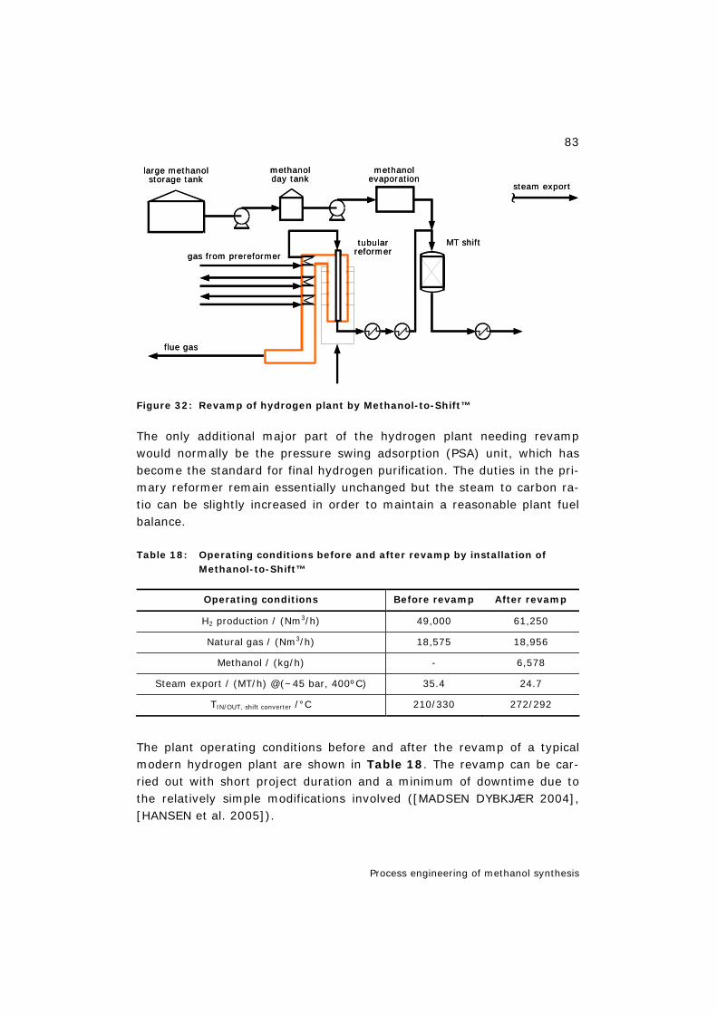
83
Process engineering of methanol synthesis
Figure 32: Revamp of hydrogen plant by Methanol-to-Shift™
The only additional major part of the hydrogen plant needing revamp would normally be the pressure swing adsorption (PSA) unit, which has become the standard for final hydrogen purification. The duties in the pri-mary reformer remain essentially unchanged but the steam to carbon ra-tio can be slightly increased in order to maintain a reasonable plant fuel balance.
Table 18: Operating conditions before and after revamp by installation of Methanol-to-Shift™
Operating conditions Before revamp After revamp
H2 production / (Nm3/h) 49,000 61,250
Natural gas / (Nm3/h) 18,575 18,956
Methanol / (kg/h) - 6,578
Steam export / (MT/h) @(~45 bar, 400ºC) 35.4 24.7
TIN/OUT, shift converter /°C 210/330 272/292
The plant operating conditions before and after the revamp of a typical modern hydrogen plant are shown in Table 18. The revamp can be car-ried out with short project duration and a minimum of downtime due to the relatively simple modifications involved ([MADSEN DYBKJÆR 2004], [HANSEN et al. 2005]).
methanolevaporation
methanolday tank
large methanolstorage tank
steam export
MT shifttubularreformergas from prereformer
flue gas
methanolevaporation
methanolday tank
large methanolstorage tank
steam export
MT shifttubularreformergas from prereformer
flue gas
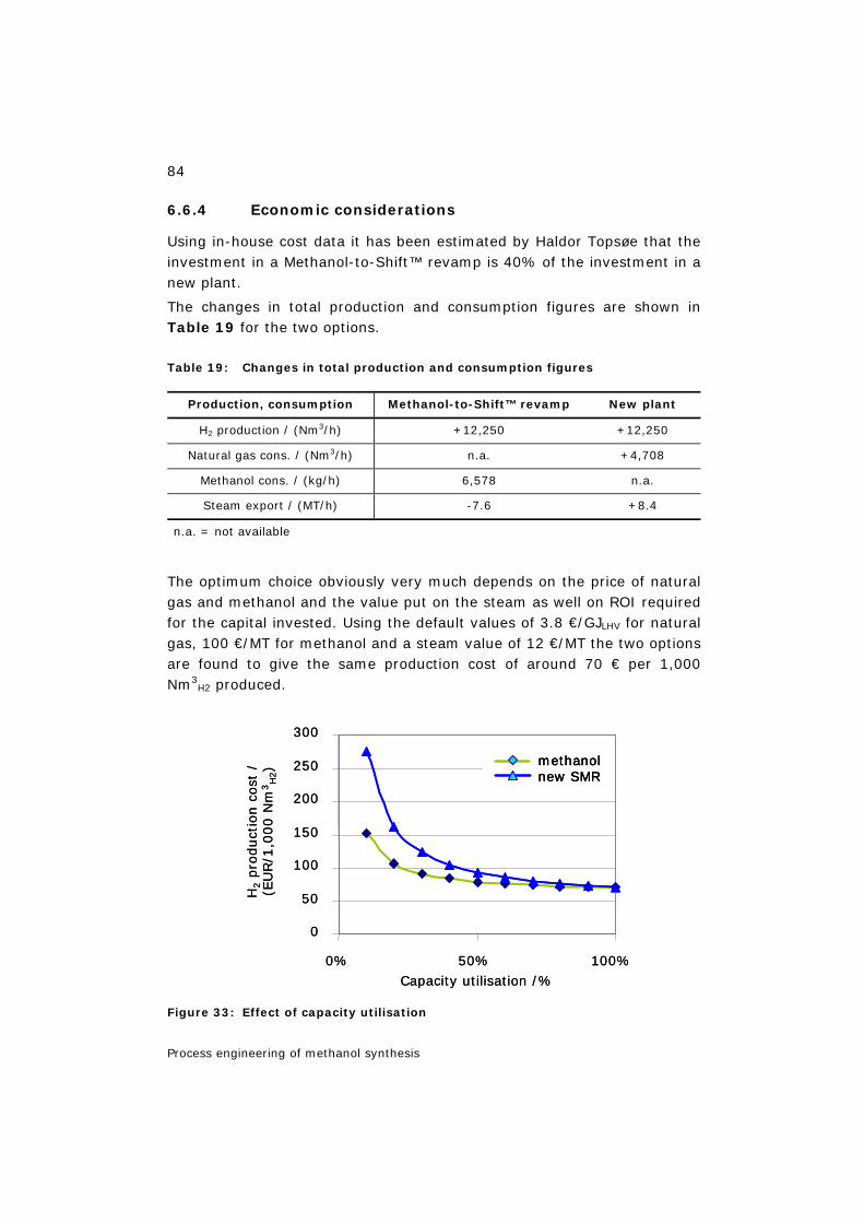
84
Process engineering of methanol synthesis
6.6.4 Economic considerations
Using in-house cost data it has been estimated by Haldor Topsøe that the investment in a Methanol-to-Shift™ revamp is 40% of the investment in a new plant.
The changes in total production and consumption figures are shown in Table 19 for the two options.
Table 19: Changes in total production and consumption figures
Production, consumption Methanol-to-Shift™ revamp New plant
H2 production / (Nm3/h) +12,250 +12,250
Natural gas cons. / (Nm3/h) n.a. +4,708
Methanol cons. / (kg/h) 6,578 n.a.
Steam export / (MT/h) -7.6 +8.4
n.a. = not available
The optimum choice obviously very much depends on the price of natural gas and methanol and the value put on the steam as well on ROI required for the capital invested. Using the default values of 3.8 €/GJLHV for natural gas, 100 €/MT for methanol and a steam value of 12 €/MT the two options are found to give the same production cost of around 70 € per 1,000 Nm3
H2 produced.
Figure 33: Effect of capacity utilisation
0
50
100
150
200
250
300
0% 50% 100%Capacity utilisation /%
H2
pro
duct
ion
cost
/ (E
UR
/1,0
00 N
m3H
2) methanol
new SMR
0
50
100
150
200
250
300
0% 50% 100%Capacity utilisation /%
H2
pro
duct
ion
cost
/ (E
UR
/1,0
00 N
m3H
2) methanol
new SMRmethanolnew SMR

85
Process engineering of methanol synthesis
This analysis, however, ignores the benefits of Methanol-to-Shift™ with respect to a very short implementation time and quick response to load change in the plant. Especially for peak shaving purposes Methanol-to-Shift™ is attractive as illustrated in Figure 33 comparing the production cost for the two options.
6.6.5 Conclusions
Revamping of hydrogen plants by introducing methanol to an existing shift reactor offers the possibility of increasing the total plant output by more than 30% with a relatively modest investment and very short implemen-tation times. The concept is especially suited for peak shaving operation where the normal feedstock is relatively expensive.
Because both the shift and methanol reforming reactions are carried out close to the optimum temperature/conversion path under almost isother-mal conditions there is ample activity available using copper-based cata-lysts.
This new process offers the possibility of using methanol (or DME) pro-duced from a variety of raw materials as a hydrogen carrier.
6.7 Use of methanol and DME in solid oxide fuel cell systems 11
6.7.1 Introduction
Methanol (MeOH) (and dimethyl ether, DME) could be attractive fuels for use in SOFC combined heat and power plants. Potentially, the fuel proc-essing steps in the plant could be very simple: ultimately being only evaporation of the methanol and injection into the anode chamber of the SOFC.
This approach would, however, lead to a number of problems and disad-vantages:
- Dry MeOH (and DME) is prone to form carbon under conditions prevail-ing in the anode chamber even with the most active Ni-cermets as the anode material as described in [SOUNDERS et al. 2004]. The amount of water needed to avoid carbon formation is calculated in [SASAKI TERA-OKA 2003].
11 Chapter 6.7 sources: figures after [HANSEN et al. 2005].
86
Process engineering of methanol synthesis
- Compared to a natural-gas-based system, more parasitic losses would be incurred for cathode air compression and the cathode air in/out ex-changer would become considerably larger for a MeOH- or DME-based system. This is due to the fact that the cathode air is used for cooling the stack and that internal reforming of methane in the anode chamber, in the case of natural gas feed, helps to cool the stack due to the endo-thermal nature of methane steam reforming. The heat of reactions for reforming methanol or DME is much less endothermic than methane steam reforming.
A process layout where all these problems are overcome has been devel-oped by adiabatically converting MeOH or DME into a mixture of methane, CO, CO2 and water. In this way, part of the chemical energy contained in the feedstock is converted to a temperature increase across the methana-tor thereby eliminating the need for an anode in/out heat exchanger and converting MeOH and DME into methane, which is much less prone to car-bon lay down than CO which could be formed from the feedstock. At the same time the chemical energy converted into latent heat in the methana-tor does no have to be removed by excess cathode air in the SOFC, thus increasing overall electric efficiency of the system.
An anode recycle stream can conveniently be included by means of an ejector upstream the methanator using as motive force methanol com-pressed by a pump and evaporated using waste heat from the system. For DME the pump is superfluous as the DME will have a sufficient vapour pressure under ambient conditions to drive the ejector recycle.
6.7.2 Methanol-based SOFC systems with methanol methanation
Based on these considerations a system with methanol as the feed and an ejector recycle of anode off-gas to the MeOH methanator inlet has been designed and is depicted in Figure 34.
In one example of the process scheme, methanol is compressed by means of pump P 1 and evaporated in E 1 by means of waste heat in the flue gas from the catalytic burner. The gas leaving E 1 acts as the motive force in ejector X 1, whereby part of the anode off-gas is recycled back to the MeOH methanator, R 1, which is loaded with a catalyst active for methanol decomposition and methanation. The gas is sent directly from the methanator to the SOFC stack.
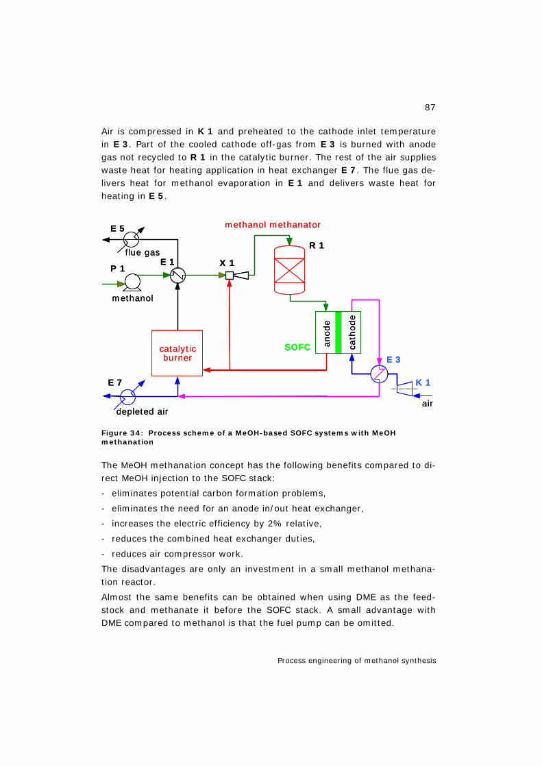
87
Process engineering of methanol synthesis
Air is compressed in K 1 and preheated to the cathode inlet temperature in E 3. Part of the cooled cathode off-gas from E 3 is burned with anode gas not recycled to R 1 in the catalytic burner. The rest of the air supplies waste heat for heating application in heat exchanger E 7. The flue gas de-livers heat for methanol evaporation in E 1 and delivers waste heat for heating in E 5.
Figure 34: Process scheme of a MeOH-based SOFC systems with MeOH methanation
The MeOH methanation concept has the following benefits compared to di-rect MeOH injection to the SOFC stack:
- eliminates potential carbon formation problems,
- eliminates the need for an anode in/out heat exchanger,
- increases the electric efficiency by 2% relative,
- reduces the combined heat exchanger duties,
- reduces air compressor work.
The disadvantages are only an investment in a small methanol methana-tion reactor.
Almost the same benefits can be obtained when using DME as the feed-stock and methanate it before the SOFC stack. A small advantage with DME compared to methanol is that the fuel pump can be omitted.
flue gas
methanol
E 7
depleted air
anode
cath
ode
methanol methanator
catalyticburner
SOFC
air
E 5
P 1 E 1 X 1
R 1
E 3
K 1
flue gas
methanol
E 7
depleted air
anode
cath
ode
methanol methanator
catalyticburner
SOFC
air
E 5
P 1 E 1 X 1
R 1
E 3
K 1
88
Process engineering of methanol synthesis
6.8 Summary of Chapter 6
Commercially used methanol technologies need three process units and a utility section: synthesis gas preparation (reforming), methanol synthesis, methanol purification and utilities. In the synthesis gas preparation sec-tion, the hydrocarbon feedstock is purified of for instance sulphur before being converted into synthesis gas at high temperature and subsequently compressed to synthesis pressure. Several reforming technologies are a-vailable for the gas conversion: one-step reforming with a tubular re-former, two-step reforming, autothermal reforming (ATR).
In the methanol synthesis section, the synthesis gas is converted to raw methanol, which contains water and minor amounts of by-products. The straight-tubed boiling water reactor is often used being the most efficient reactor type. Water and by-products are removed in the methanol distilla-tion section. The conventional layout is with a two-column system. The Topsøe system features a split concentration column and an optional ethanol column. The utility section comprises water treatment, cooling water system, auxiliary boiler, power production, and other installations as required for the proper operation of the plant. Typical capacities for world-scale methanol plants have been in the range of 1,500–2,500 MTPD. Lately, the trend has been to obtain lower production costs by building even larger plants to achieve economy of scale.
DME as a clean fuel is very interesting for the market. Possible applica-tions are LPG substitution, diesel fuel, fuel in power plants, hydrogen car-rier and chemical intermediate (feed for MTO plants, synthetic gasoline, etc.). Three routes for the production of DME dominate both the produc-tion and the literature on the subject: methanol/DME co-production, methanol dehydration and direct synthesis.
Both methanol (MeOH) and dimethyl ether (DME) can be seen as conven-ient energy carriers as both chemicals can be easily steam reformed to generate hydrogen with a high yield. A novel concept has been invented where the steam reforming of methanol or DME is carried out concurrently with the water gas shift reaction in the existing shift reactors in hydrogen plants. Revamping of hydrogen plants by introducing methanol to an ex-isting shift reactor offers the possibility of increasing the total plant output with a relatively modest investment and very short implementation times. This new process offers the possibility of using methanol (or DME) pro-duced from a variety of raw materials as a hydrogen carrier.
89
Methanol technologies
7 Methanol technologies 12
After having described the conventional technology for methanol produc-tion (Chapter 4), future-oriented methanol technologies will be presented in the following. A compilation of different Lurgi processes can be found in Table 35.
7.1 Natural gas-to-methanol
The MegaMethanol® process is a future-oriented technology for the con-version of natural gas into methanol in large quantities and at low cost. This technology enables the construction of single-line plants with high ef-ficiency and more than twice the production capacity of today's methanol plants. This permits the use of methanol in new downstream processes (DME, polypropylene).
7.1.1 The concept
The MegaMethanol® technology was developed for large plants with a ca-pacity of > 1 million t/y (3,000 t/d) of methanol. In order to achieve such capacities, a special process design is needed, which is based on a modern but proven and reliable technology, a cost-optimized energy use, high en-vironmental compatibility and low investment costs [GÖHNA 1997].
The essential features of this technology are:
– autothermal natural gas reforming with oxygen supply in combination with steam reforming or as pure autothermal reforming,
– two-stage methanol synthesis with water- and gas-cooled reactors ena-bling operation under optimum reaction conditions,
– adjustable synthesis gas composition by the mode of operation of the hydrogen loop.
7.1.2 Synthesis gas production
The costs for the production unit of the synthesis gas account for ap-proximately 50% of the investment costs of a methanol plant. The optimi-sation of this plant component therefore holds the greatest potential for cost savings.
12 Chapter 7 is based on: Bielawa in [METHANOL 2003], Chapter 5. Updated by Liebner
90
Methanol technologies
Pure conventional steam reforming is only economically efficient in small and medium-sized methanol plants and technically limited to a maximum capacity of about 3,000 t/d of methanol for single-strand plants. Oxygen-based natural gas reforming, both in combination with steam reforming and as pure autothermal reforming, is regarded today as the best concept for large synthesis gas plants [CHRISTENSEN PRIMDAHL 1994].
The configuration of the reforming process (cf. eq. 4.1 in Chapter 4.1.1) essentially depends on the composition of the feedstock, which may range from light natural gas (nearly 100% methane content) up to associated gas. The aim of the reforming process is in all cases the production of an optimum synthesis gas for methanol production (cf. eq. 4.2 in Chap-ter 4.1.2), which is characterized by the stoichiometric number SR
13 de-fined in the following: SR = (H2-CO2) / (CO+CO2) = 2.0–2.1.
7.1.3 Autothermal reforming
Pure autothermal reforming can be used for synthesis gas production whenever light natural gas is available as a feedstock.
The desulphurized and (optionally) prereformed natural gas is reformed with steam and oxygen as the reforming agent at about 40 bars to obtain synthesis gas. The process provides great flexibility, so that operation can be adapted to the specific requirements over large ranges. The reformer outlet temperatures are in the range of 950–1,050 °C. The synthesis gas is compressed to the pressure required for methanol synthesis in a syn-thesis gas compressor with integrated recycle stage.
Even if pure methane is used as the feedstock for autothermal reforming, it is necessary to condition the synthesis gas since the stoichiometric number is smaller than 2.0. The most effective way to achieve the gas composition required is the addition of hydrogen, which is obtained from a purge gas flow of methanol synthesis by means of a membrane assembly or a pressure swing adsorption unit (PSA).
7.1.4 Combined reforming
In the case of using heavy natural gases and associated gas, the stoichiometric number required cannot be achieved, even if all the hydro-gen available in the purge gas is fed to the synthesis gas. In these cases, the MegaMethanol® concept provides for a combination of autothermal and
13 SR is equal to the module M (cf. Chapter 5.2.2, 5.3.1 and 6.2.3)
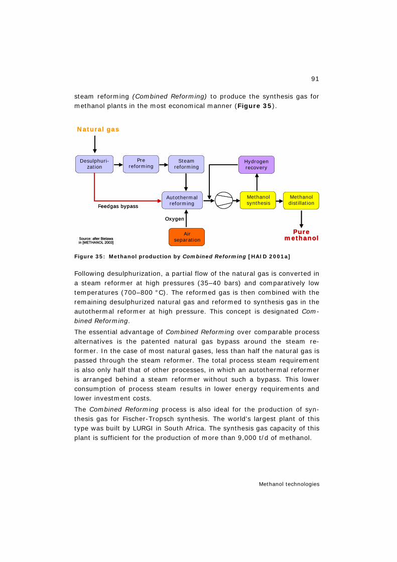
91
Methanol technologies
steam reforming (Combined Reforming) to produce the synthesis gas for methanol plants in the most economical manner (Figure 35).
Figure 35: Methanol production by Combined Reforming [HAID 2001a]
Following desulphurization, a partial flow of the natural gas is converted in a steam reformer at high pressures (35–40 bars) and comparatively low temperatures (700–800 °C). The reformed gas is then combined with the remaining desulphurized natural gas and reformed to synthesis gas in the autothermal reformer at high pressure. This concept is designated Com-bined Reforming.
The essential advantage of Combined Reforming over comparable process alternatives is the patented natural gas bypass around the steam re-former. In the case of most natural gases, less than half the natural gas is passed through the steam reformer. The total process steam requirement is also only half that of other processes, in which an autothermal reformer is arranged behind a steam reformer without such a bypass. This lower consumption of process steam results in lower energy requirements and lower investment costs.
The Combined Reforming process is also ideal for the production of syn-thesis gas for Fischer-Tropsch synthesis. The world's largest plant of this type was built by LURGI in South Africa. The synthesis gas capacity of this plant is sufficient for the production of more than 9,000 t/d of methanol.
Steamreforming
Methanolsynthesis
Methanoldistillation
Autothermalreforming
Hydrogenrecovery
Prereforming
Desulphuri-zation
Natural gas
Puremethanol
Airseparation
Oxygen
Feedgas bypass
Source: after Bielawain [METHANOL 2003]
Steamreforming
Methanolsynthesis
Methanoldistillation
Autothermalreforming
Hydrogenrecovery
Prereforming
Desulphuri-zation
Natural gas
Puremethanol
Airseparation
Airseparation
Oxygen
Feedgas bypass
Source: after Bielawain [METHANOL 2003]
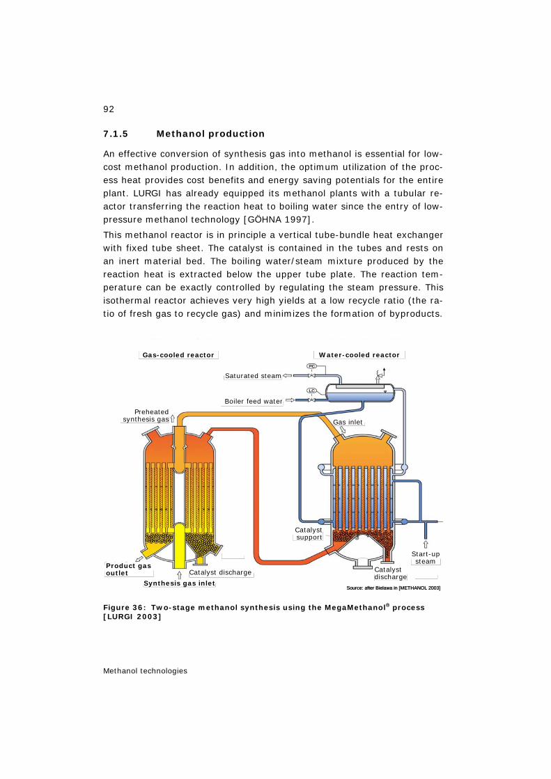
92
Methanol technologies
7.1.5 Methanol production
An effective conversion of synthesis gas into methanol is essential for low-cost methanol production. In addition, the optimum utilization of the proc-ess heat provides cost benefits and energy saving potentials for the entire plant. LURGI has already equipped its methanol plants with a tubular re-actor transferring the reaction heat to boiling water since the entry of low-pressure methanol technology [GÖHNA 1997].
This methanol reactor is in principle a vertical tube-bundle heat exchanger with fixed tube sheet. The catalyst is contained in the tubes and rests on an inert material bed. The boiling water/steam mixture produced by the reaction heat is extracted below the upper tube plate. The reaction tem-perature can be exactly controlled by regulating the steam pressure. This isothermal reactor achieves very high yields at a low recycle ratio (the ra-tio of fresh gas to recycle gas) and minimizes the formation of byproducts.
Figure 36: Two-stage methanol synthesis using the MegaMethanol® process [LURGI 2003]
Saturated steam
Boiler feed water
Gas inletPreheated
synthesis gas
Catalystsupport
Start-upsteam
Catalystdischarge
Catalyst discharge
Synthesis gas inlet
Product gasoutlet
Man
Man
Gas-cooled reactor Water-cooled reactor
Source: after Bielawa in [METHANOL 2003]
Saturated steam
Boiler feed water
Gas inletPreheated
synthesis gas
Catalystsupport
Start-upsteam
Catalystdischarge
Catalyst discharge
Synthesis gas inlet
Product gasoutlet
Man
Man
Gas-cooled reactor Water-cooled reactor
Source: after Bielawa in [METHANOL 2003]
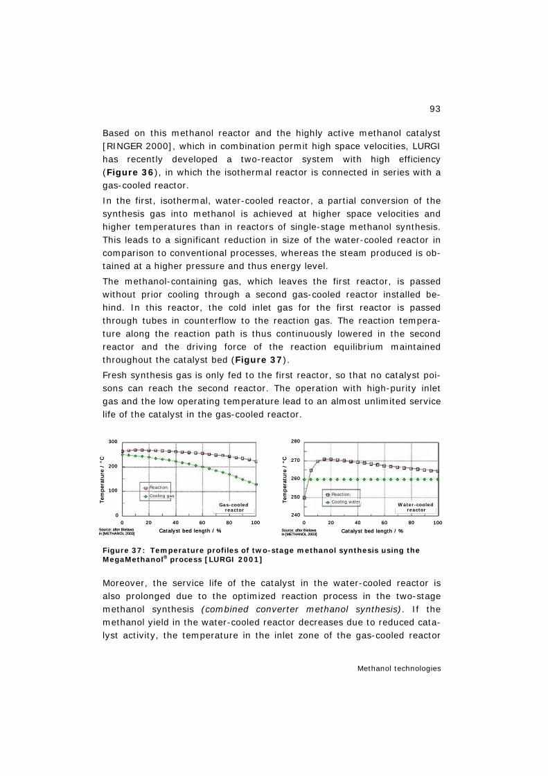
93
Methanol technologies
Based on this methanol reactor and the highly active methanol catalyst [RINGER 2000], which in combination permit high space velocities, LURGI has recently developed a two-reactor system with high efficiency (Figure 36), in which the isothermal reactor is connected in series with a gas-cooled reactor.
In the first, isothermal, water-cooled reactor, a partial conversion of the synthesis gas into methanol is achieved at higher space velocities and higher temperatures than in reactors of single-stage methanol synthesis. This leads to a significant reduction in size of the water-cooled reactor in comparison to conventional processes, whereas the steam produced is ob-tained at a higher pressure and thus energy level.
The methanol-containing gas, which leaves the first reactor, is passed without prior cooling through a second gas-cooled reactor installed be-hind. In this reactor, the cold inlet gas for the first reactor is passed through tubes in counterflow to the reaction gas. The reaction tempera-ture along the reaction path is thus continuously lowered in the second reactor and the driving force of the reaction equilibrium maintained throughout the catalyst bed (Figure 37).
Fresh synthesis gas is only fed to the first reactor, so that no catalyst poi-sons can reach the second reactor. The operation with high-purity inlet gas and the low operating temperature lead to an almost unlimited service life of the catalyst in the gas-cooled reactor.
Figure 37: Temperature profiles of two-stage methanol synthesis using the MegaMethanol® process [LURGI 2001]
Moreover, the service life of the catalyst in the water-cooled reactor is also prolonged due to the optimized reaction process in the two-stage methanol synthesis (combined converter methanol synthesis). If the methanol yield in the water-cooled reactor decreases due to reduced cata-lyst activity, the temperature in the inlet zone of the gas-cooled reactor
0
300
200
100
0
20 40 60 80 100
Catalyst bed length / %
Tem
per
ature
/ °C
Gas-cooledreactor
Reaction
Cooling gas
Source: after Bielawain [METHANOL 2003]
0
300
200
100
0
20 40 60 80 100
Catalyst bed length / %
Tem
per
ature
/ °C
Gas-cooledreactor
Reaction
Cooling gas
Source: after Bielawain [METHANOL 2003]
0 20 40 60 80 100
280
270
260
250
240
Catalyst bed length / %
Tem
per
ature
/ °C
Water-cooledreactor
Reaction
Cooling water
Source: after Bielawain [METHANOL 2003]
0 20 40 60 80 100
280
270
260
250
240
Catalyst bed length / %
Tem
per
ature
/ °C
Water-cooledreactor
Reaction
Cooling water
Source: after Bielawain [METHANOL 2003]

94
Methanol technologies
will rise, which improves the reaction kinetics and thus increases the methanol yield in the second reactor.
After cooling the reaction mixture and separating the crude methanol from the non-converted reaction gas, the crude methanol is processed in the distillation unit. In the hydrogen recovery unit, hydrogen is separated from a purge gas partial flow and recycled into the synthesis gas loop. The remaining methane-rich gas is used for underfiring.
Figure 38: Two-stage methanol synthesis with 3-column distillation [GÖHNA 1997]
The essential advantages of the two-stage methanol synthesis (Figure 38) are:
– High efficiency of synthesis gas conversion: at the same rate of conver-sion, the recycle ratio (fresh gas/recycle gas) is only about half as high as in a single-stage water-cooled reactor.
– High energy efficiency: about 0.8 t of steam per ton of methanol can be produced at 50–60 bars. Moreover, a considerable proportion of the free heat at the outlet of the gas-cooled reactor can be recovered.
– Low investment costs: due to the reduction of the catalyst volume for the water-cooled reactor, the omission of the large inlet gas preheater
Gas forunderfiering
Puremethanol
Gas-cooledreactor
Water-cooledreactor
Process waterto saturator
Foreruncolumn
Puremethanolcolumn
(elevatedpressure)
Puremethanolcolumn(atmos-pheric)
Boiler feed waterto reforming unit
Synthesis gas /recycle gascompressor
Reformedgas
High-pressuresteam
Powerswing
adsorption
H2
Superheatedhigh-pressuresteam
Low-pressuresteam
Expansiontank
Boiler feedwater
Synthesisgas
Source: after Bielawa in [METHANOL 2003]
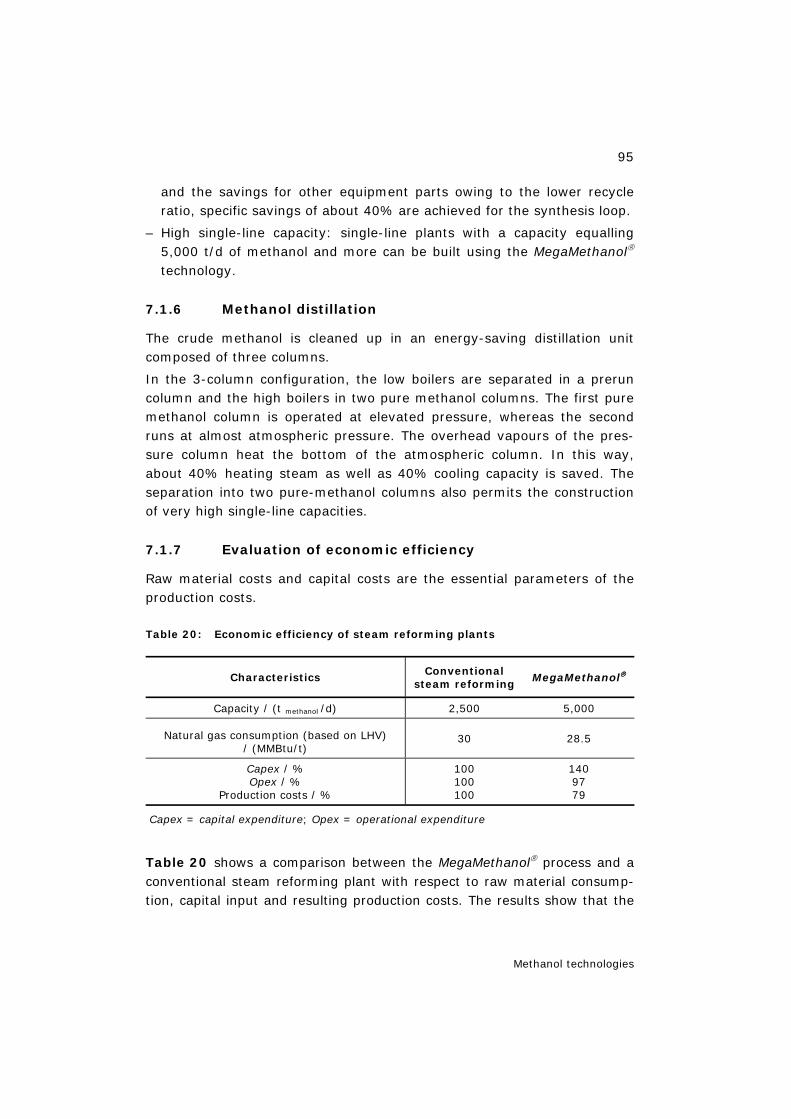
95
Methanol technologies
and the savings for other equipment parts owing to the lower recycle ratio, specific savings of about 40% are achieved for the synthesis loop.
– High single-line capacity: single-line plants with a capacity equalling 5,000 t/d of methanol and more can be built using the MegaMethanol® technology.
7.1.6 Methanol distillation
The crude methanol is cleaned up in an energy-saving distillation unit composed of three columns.
In the 3-column configuration, the low boilers are separated in a prerun column and the high boilers in two pure methanol columns. The first pure methanol column is operated at elevated pressure, whereas the second runs at almost atmospheric pressure. The overhead vapours of the pres-sure column heat the bottom of the atmospheric column. In this way, about 40% heating steam as well as 40% cooling capacity is saved. The separation into two pure-methanol columns also permits the construction of very high single-line capacities.
7.1.7 Evaluation of economic efficiency
Raw material costs and capital costs are the essential parameters of the production costs.
Table 20: Economic efficiency of steam reforming plants
Characteristics Conventional steam reforming
MegaMethanol®
Capacity / (t methanol /d) 2,500 5,000
Natural gas consumption (based on LHV) / (MMBtu/t)
30 28.5
Capex / % Opex / %
Production costs / %
100 100 100
140 97 79
Capex = capital expenditure; Opex = operational expenditure
Table 20 shows a comparison between the MegaMethanol® process and a conventional steam reforming plant with respect to raw material consump-tion, capital input and resulting production costs. The results show that the
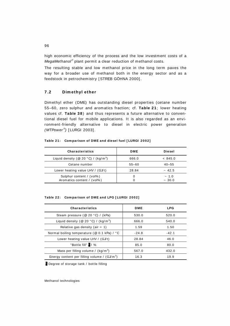
96
Methanol technologies
high economic efficiency of the process and the low investment costs of a MegaMethanol® plant permit a clear reduction of methanol costs.
The resulting stable and low methanol price in the long term paves the way for a broader use of methanol both in the energy sector and as a feedstock in petrochemistry [STREB GÖHNA 2000].
7.2 Dimethyl ether
Dimethyl ether (DME) has outstanding diesel properties (cetane number 55–60, zero sulphur and aromatics fraction; cf. Table 21; lower heating values cf. Table 38) and thus represents a future alternative to conven-tional diesel fuel for mobile applications. It is also regarded as an envi-ronment-friendly alternative to diesel in electric power generation (MTPower®) [LURGI 2003].
Table 21: Comparison of DME and diesel fuel [LURGI 2002]
Characteristics DME Diesel
Liquid density (@ 20 °C) / (kg/m3) 666.0 < 845.0
Cetane number 55–60 40–55
Lower heating value LHV / (GJ/t) 28.84 ~ 42.5
Sulphur content / (vol%) Aromatics content / (vol%)
0 0
~ 1.0 ~ 30.0
Table 22: Comparison of DME and LPG [LURGI 2002]
Characteristics DME LPG
Steam pressure (@ 20 °C) / (kPa) 530.0 520.0
Liquid density (@ 20 °C) / (kg/m3) 666.0 540.0
Relative gas density (air = 1) 1.59 1.50
Normal boiling temperature (@ 0.1 kPa) / °C -24.8 -42.1
Lower heating value LHV / (GJ/t) 28.84 46.0
"Bottle fill” * / % 85.0 80.0
Mass per filling volume / (kg/m3) 567.0 432.0
Energy content per filling volume / (GJ/m3) 16.3 19.9
* Degree of storage tank / bottle filling
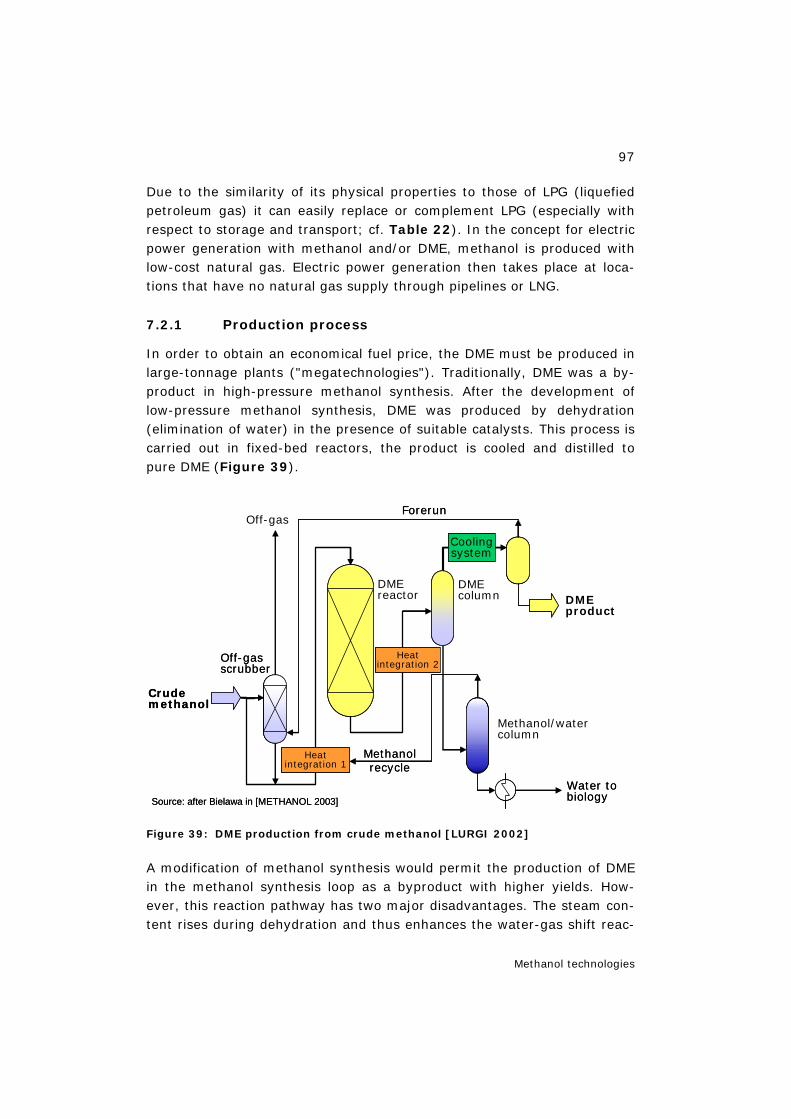
97
Methanol technologies
Due to the similarity of its physical properties to those of LPG (liquefied petroleum gas) it can easily replace or complement LPG (especially with respect to storage and transport; cf. Table 22). In the concept for electric power generation with methanol and/or DME, methanol is produced with low-cost natural gas. Electric power generation then takes place at loca-tions that have no natural gas supply through pipelines or LNG.
7.2.1 Production process
In order to obtain an economical fuel price, the DME must be produced in large-tonnage plants ("megatechnologies"). Traditionally, DME was a by-product in high-pressure methanol synthesis. After the development of low-pressure methanol synthesis, DME was produced by dehydration (elimination of water) in the presence of suitable catalysts. This process is carried out in fixed-bed reactors, the product is cooled and distilled to pure DME (Figure 39).
Figure 39: DME production from crude methanol [LURGI 2002]
A modification of methanol synthesis would permit the production of DME in the methanol synthesis loop as a byproduct with higher yields. How-ever, this reaction pathway has two major disadvantages. The steam con-tent rises during dehydration and thus enhances the water-gas shift reac-
Heatintegration 2
Heatintegration 1
Off-gasForerun
DMEreactor
DMEcolumn DME
product
Methanol/watercolumn
Water tobiology
Methanol recycle
Crudemethanol
Off-gasscrubber
Source: after Bielawa in [METHANOL 2003]
Coolingsystem
Heatintegration 2
Heatintegration 1
Off-gasForerun
DMEreactor
DMEcolumn DME
product
Methanol/watercolumn
Water tobiology
Methanol recycle
Crudemethanol
Off-gasscrubber
Source: after Bielawa in [METHANOL 2003]
Coolingsystem

98
Methanol technologies
tion. The quality of the synthesis gas deteriorates due to the conversion of CO into CO2. The kinetics of the reaction of CO2 and H2 is slower than that of CO and H2. Consequently, the synthesis catalyst and the recycle volume must be increased. In addition, a low-temperature separation of the DME is required due to its low boiling point [BALTHASAR HILSEBEIN 2003].
In the case of combining a DME unit with a MegaMethanol® plant it is pos-sible to reduce the methanol distillation unit from a 3-column configura-tion to a single-column system, which involves corresponding savings.
In the MegaDME process (methanol-to-DME, MTD) all types and grades of DME can be produced. The different requirements for fuels, electric power generation (MTPower®) or pure DME can be met by varying the size and design of the DME distillation columns.
7.2.2 Evaluation of economic efficiency
The economic efficiency of the MegaDME process is summarized in Table 23, making the following assumptions:
– natural gas consumption and product value are normalized to one methanol equivalent (capacity: 7,500 t/d of methanol),
– the DME product quality corresponds to the given specifications,
– natural gas consumption figures comprise the energy requirement for an air separation and an electricity production unit,
– total fixed costs comprise an air separation unit, an electricity produc-tion unit and utility units,
– the natural gas price was assumed to be 1.0 US$/MMBtu,
– depreciation was assumed to be 10% of the total fixed costs,
Table 23: Economic efficiency of the MegaDME process [LURGI 2003]
Characteristics and costs MegaMethanol® &
dehydration
DME capacity / (t/d) 5,000
/ (MMBtu/tmethanol) 28.5 Specific natural gas consumption / (MMBtu/tDME) 40.2
Total fixed costs (EPC 1) / (million US$) 750 2
DME production costs / (US$ / tDME) 152 2
1 engineering, procurement and construction; 2 extrapolated 2003 —> 2006

99
Methanol technologies
– the ROI (return on investment) was fixed at 20% of the total fixed costs,
– operating costs for plant, personnel, plant overhead costs, servic-ing/maintenance work and material are included.
The investment costs are budget cost estimates with an accuracy of ±30%, specific site factors are not included in these figures.
DME, a traditional methanol derivative, thus represents a promising alter-native fuel to diesel, LPG, for electricity production and also for olefin pro-duction if produced in large quantities. DME production by dehydrating methanol is a more economical approach than the simultaneous produc-tion of methanol and DME. Figure 40 shows a price comparison for DME with diesel fuel and LPG as of 2002/2003 and Table 24 the same for 2006.
Figure 40: Comparison of DME with diesel and LPG ([LIEBNER 2002] LPG prices [CHEMSYSTEMS 2003])
Table 24: DME compared with diesel and LPG 2006 [LIEBNER 2006]
Fuel Costs / ($/MMBtu)
DME Production cost Transportation cost
Delivered cost (“trans-ocean”)
5–7 1 0.5–1 1 6–8 1
Diesel 14 1 2
LPG 11.4 1 2
1 Based on natural gas price = 1 US$/MMBtu and both depreciation & ROI 10% of total fixed costs; 2 as of March 2006
Diesel
DME @ natural gas pricesA 0.70 US$/MMBtuB 0.50 US$/MMBtuC 0.25 US$/MMBtuP
rice
/ (U
S$/
MM
Btu)
Price / (US$/bbl crude oil)15 20 25 30
8
6
4
2
0
a
Source: after Bielawain [METHANOL 2003]
Diesel
DME @ natural gas pricesA 0.70 US$/MMBtuB 0.50 US$/MMBtuC 0.25 US$/MMBtuP
rice
/ (U
S$/
MM
Btu)
Price / (US$/bbl crude oil)15 20 25 30
8
6
4
2
0
a
Source: after Bielawain [METHANOL 2003]
DME
LPG Japan
LPG India
Pric
e / (
US
$/M
MB
tu)
Natural gas price / (US$/MMBtu)0.25 0.5 0.7
6
5
4
3
2
1
0
a
Source: after Bielawain [METHANOL 2003]
DME
LPG Japan
LPG India
Pric
e / (
US
$/M
MB
tu)
Natural gas price / (US$/MMBtu)0.25 0.5 0.7
6
5
4
3
2
1
0
a
Source: after Bielawain [METHANOL 2003]
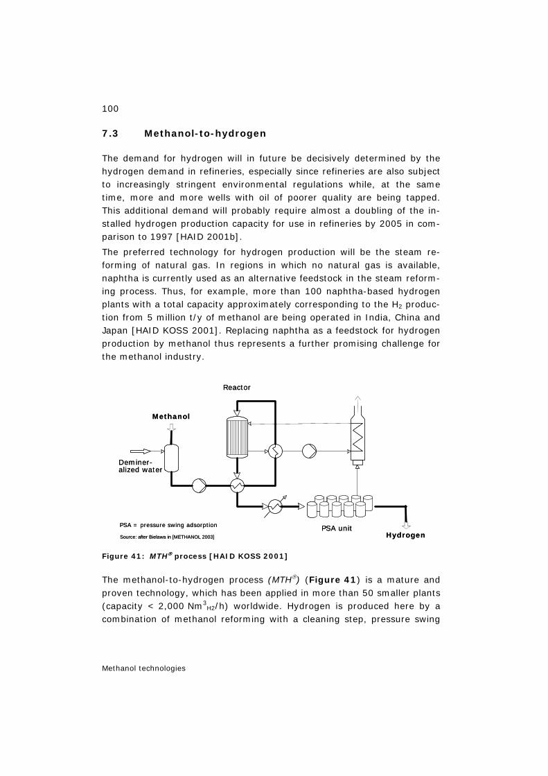
100
Methanol technologies
7.3 Methanol-to-hydrogen
The demand for hydrogen will in future be decisively determined by the hydrogen demand in refineries, especially since refineries are also subject to increasingly stringent environmental regulations while, at the same time, more and more wells with oil of poorer quality are being tapped. This additional demand will probably require almost a doubling of the in-stalled hydrogen production capacity for use in refineries by 2005 in com-parison to 1997 [HAID 2001b].
The preferred technology for hydrogen production will be the steam re-forming of natural gas. In regions in which no natural gas is available, naphtha is currently used as an alternative feedstock in the steam reform-ing process. Thus, for example, more than 100 naphtha-based hydrogen plants with a total capacity approximately corresponding to the H2 produc-tion from 5 million t/y of methanol are being operated in India, China and Japan [HAID KOSS 2001]. Replacing naphtha as a feedstock for hydrogen production by methanol thus represents a further promising challenge for the methanol industry.
Figure 41: MTH® process [HAID KOSS 2001]
The methanol-to-hydrogen process (MTH®) (Figure 41) is a mature and proven technology, which has been applied in more than 50 smaller plants (capacity < 2,000 Nm3
H2/h) worldwide. Hydrogen is produced here by a combination of methanol reforming with a cleaning step, pressure swing
Methanol
Reactor
Hydrogen
Deminer-alized water
PSA unitPSA = pressure swing adsorption
Source: after Bielawa in [METHANOL 2003]
Methanol
Reactor
Hydrogen
Deminer-alized water
PSA unitPSA = pressure swing adsorption
Source: after Bielawa in [METHANOL 2003]
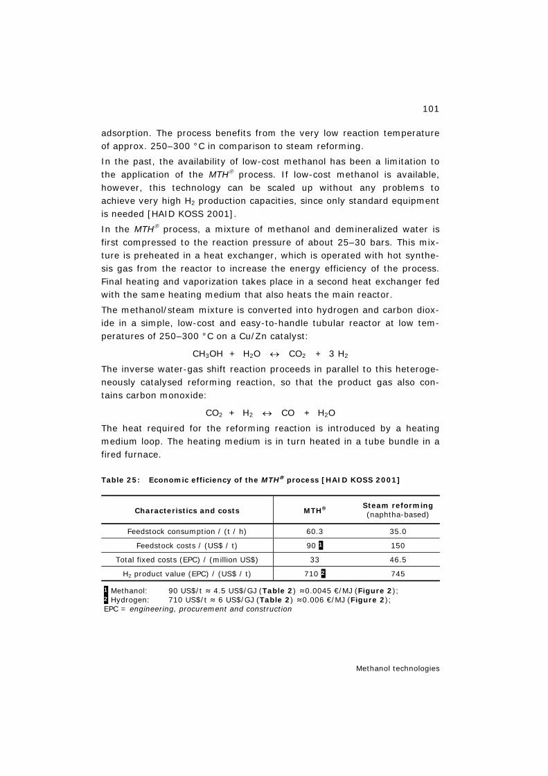
101
Methanol technologies
adsorption. The process benefits from the very low reaction temperature of approx. 250–300 °C in comparison to steam reforming.
In the past, the availability of low-cost methanol has been a limitation to the application of the MTH® process. If low-cost methanol is available, however, this technology can be scaled up without any problems to achieve very high H2 production capacities, since only standard equipment is needed [HAID KOSS 2001].
In the MTH® process, a mixture of methanol and demineralized water is first compressed to the reaction pressure of about 25–30 bars. This mix-ture is preheated in a heat exchanger, which is operated with hot synthe-sis gas from the reactor to increase the energy efficiency of the process. Final heating and vaporization takes place in a second heat exchanger fed with the same heating medium that also heats the main reactor.
The methanol/steam mixture is converted into hydrogen and carbon diox-ide in a simple, low-cost and easy-to-handle tubular reactor at low tem-peratures of 250–300 °C on a Cu/Zn catalyst:
CH3OH + H2O ↔ CO2 + 3 H2
The inverse water-gas shift reaction proceeds in parallel to this heteroge-neously catalysed reforming reaction, so that the product gas also con-tains carbon monoxide:
CO2 + H2 ↔ CO + H2O
The heat required for the reforming reaction is introduced by a heating medium loop. The heating medium is in turn heated in a tube bundle in a fired furnace.
Table 25: Economic efficiency of the MTH® process [HAID KOSS 2001]
Characteristics and costs MTH® Steam reforming (naphtha-based)
Feedstock consumption / (t / h) 60.3 35.0
Feedstock costs / (US$ / t) 90 1 150
Total fixed costs (EPC) / (million US$) 33 46.5
H2 product value (EPC) / (US$ / t) 710 2 745
1 Methanol: 90 US$/t ≈ 4.5 US$/GJ (Table 2) ≈0.0045 €/MJ (Figure 2); 2 Hydrogen: 710 US$/t ≈ 6 US$/GJ (Table 2) ≈0.006 €/MJ (Figure 2); EPC = engineering, procurement and construction
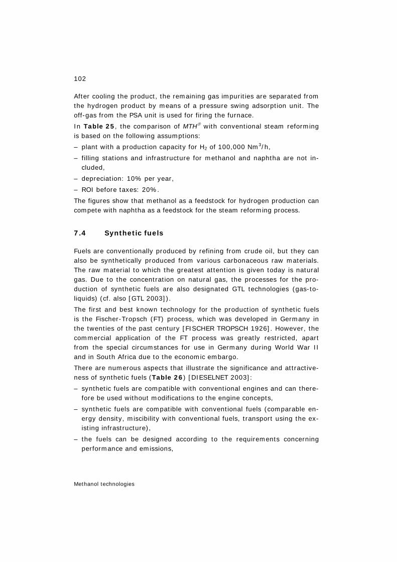
102
Methanol technologies
After cooling the product, the remaining gas impurities are separated from the hydrogen product by means of a pressure swing adsorption unit. The off-gas from the PSA unit is used for firing the furnace.
In Table 25, the comparison of MTH® with conventional steam reforming is based on the following assumptions:
– plant with a production capacity for H2 of 100,000 Nm3/h,
– filling stations and infrastructure for methanol and naphtha are not in-cluded,
– depreciation: 10% per year,
– ROI before taxes: 20%.
The figures show that methanol as a feedstock for hydrogen production can compete with naphtha as a feedstock for the steam reforming process.
7.4 Synthetic fuels
Fuels are conventionally produced by refining from crude oil, but they can also be synthetically produced from various carbonaceous raw materials. The raw material to which the greatest attention is given today is natural gas. Due to the concentration on natural gas, the processes for the pro-duction of synthetic fuels are also designated GTL technologies (gas-to-liquids) (cf. also [GTL 2003]).
The first and best known technology for the production of synthetic fuels is the Fischer-Tropsch (FT) process, which was developed in Germany in the twenties of the past century [FISCHER TROPSCH 1926]. However, the commercial application of the FT process was greatly restricted, apart from the special circumstances for use in Germany during World War II and in South Africa due to the economic embargo.
There are numerous aspects that illustrate the significance and attractive-ness of synthetic fuels (Table 26) [DIESELNET 2003]:
– synthetic fuels are compatible with conventional engines and can there-fore be used without modifications to the engine concepts,
– synthetic fuels are compatible with conventional fuels (comparable en-ergy density, miscibility with conventional fuels, transport using the ex-isting infrastructure),
– the fuels can be designed according to the requirements concerning performance and emissions,
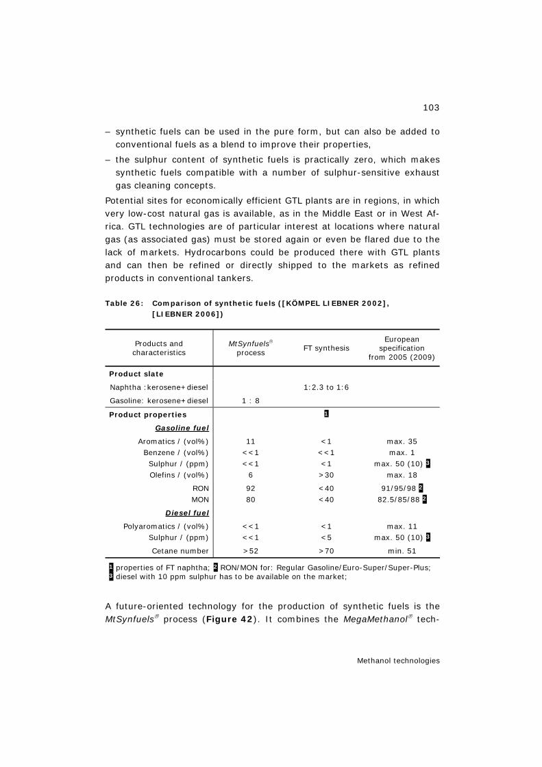
103
Methanol technologies
– synthetic fuels can be used in the pure form, but can also be added to conventional fuels as a blend to improve their properties,
– the sulphur content of synthetic fuels is practically zero, which makes synthetic fuels compatible with a number of sulphur-sensitive exhaust gas cleaning concepts.
Potential sites for economically efficient GTL plants are in regions, in which very low-cost natural gas is available, as in the Middle East or in West Af-rica. GTL technologies are of particular interest at locations where natural gas (as associated gas) must be stored again or even be flared due to the lack of markets. Hydrocarbons could be produced there with GTL plants and can then be refined or directly shipped to the markets as refined products in conventional tankers.
Table 26: Comparison of synthetic fuels ([KÖMPEL LIEBNER 2002], [LIEBNER 2006])
Products and characteristics
MtSynfuels® process
FT synthesis European
specification from 2005 (2009)
Product slate
Naphtha :kerosene+diesel 1:2.3 to 1:6
Gasoline: kerosene+diesel 1 : 8
Product properties 1
Gasoline fuel
Aromatics / (vol%) Benzene / (vol%) Sulphur / (ppm) Olefins / (vol%)
11 <<1 <<1
6
<1 <<1 <1 >30
max. 35 max. 1
max. 50 (10) 3 max. 18
RON MON
92 80
<40 <40
91/95/98 2
82.5/85/88 2
Diesel fuel
Polyaromatics / (vol%) Sulphur / (ppm)
<<1 <<1
<1 <5
max. 11 max. 50 (10) 3
Cetane number >52 >70 min. 51
1 properties of FT naphtha; 2 RON/MON for: Regular Gasoline/Euro-Super/Super-Plus; 3 diesel with 10 ppm sulphur has to be available on the market;
A future-oriented technology for the production of synthetic fuels is the MtSynfuels® process (Figure 42). It combines the MegaMethanol® tech-
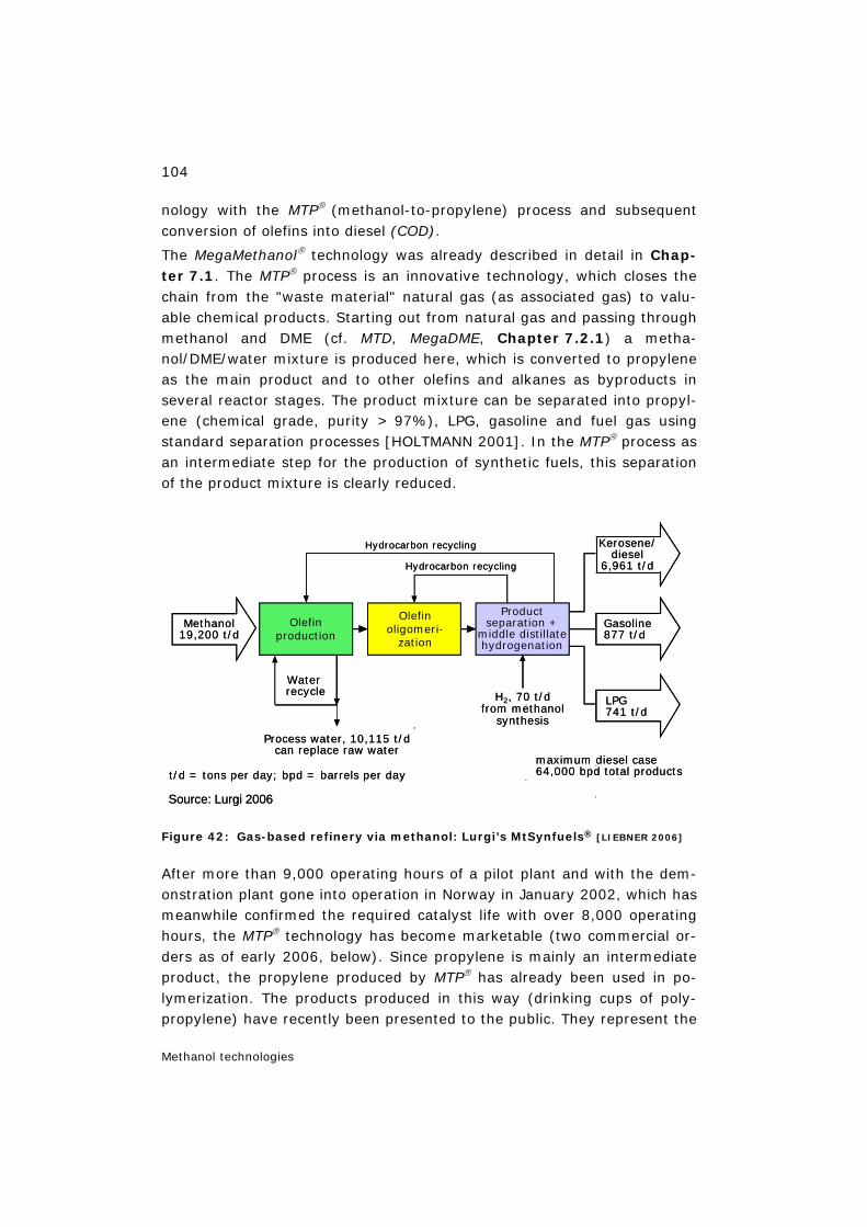
104
Methanol technologies
nology with the MTP® (methanol-to-propylene) process and subsequent conversion of olefins into diesel (COD).
The MegaMethanol® technology was already described in detail in Chap-ter 7.1. The MTP® process is an innovative technology, which closes the chain from the "waste material" natural gas (as associated gas) to valu-able chemical products. Starting out from natural gas and passing through methanol and DME (cf. MTD, MegaDME, Chapter 7.2.1) a metha-nol/DME/water mixture is produced here, which is converted to propylene as the main product and to other olefins and alkanes as byproducts in several reactor stages. The product mixture can be separated into propyl-ene (chemical grade, purity > 97%), LPG, gasoline and fuel gas using standard separation processes [HOLTMANN 2001]. In the MTP® process as an intermediate step for the production of synthetic fuels, this separation of the product mixture is clearly reduced.
Figure 42: Gas-based refinery via methanol: Lurgi’s MtSynfuels® [LIEBNER 2006]
After more than 9,000 operating hours of a pilot plant and with the dem-onstration plant gone into operation in Norway in January 2002, which has meanwhile confirmed the required catalyst life with over 8,000 operating hours, the MTP® technology has become marketable (two commercial or-ders as of early 2006, below). Since propylene is mainly an intermediate product, the propylene produced by MTP® has already been used in po-lymerization. The products produced in this way (drinking cups of poly-propylene) have recently been presented to the public. They represent the
Productseparation +
middle distillatehydrogenation
Waterrecycle
Process water, 10,115 t/dcan replace raw water
Olefinproduction
Olefinoligomeri-
zation
Hydrocarbon recycling
Hydrocarbon recycling
Gasoline877 t/d
LPG741 t/d
Methanol19,200 t/d
H2, 70 t/dfrom methanol
synthesis
Kerosene/diesel
6,961 t/d
t/d = tons per day; bpd = barrels per day
Source: Lurgi 2006
maximum diesel case64,000 bpd total products
105
Methanol technologies
first consumer good produced from natural gas and clearly illustrate the bridging from natural gas to a valuable product.
The MTP® process is an exemplary technology for the pioneering route from natural gas to valuable petrochemical products (gas to petrochemi-cals). These technologies serve to develop ecologically and economically lucrative alternatives to the oil-based production routes. Nearly all process steps are technically proven. The economic efficiency of these alternative routes mainly depends on the ratio of the natural gas price to the crude oil price and is increasingly given with further crude oil shortage.
The COD technology was applied as early as 1992 in a plant in South Africa and has proven its reliability since the plant was put into operation in 1993.
The MtSynfuels® process is used to produce kerosene and diesel as the main products and gasoline and light oil as byproducts from methanol in the multistage process described. The individual process stages are inter-laced through raw material recycling.
The comparative economic analyses of synthetic fuels summarized in Table 27 and Table 28 are based on the following assumptions:
– plant site: Middle East,
– plant capacity: 64,000 bbl/d of products,
– natural gas price: 0.70 US$/MMBtu,
– depreciation: 10% for installations inside the plant boundaries, 5% for installations outside the plant boundaries,
– ROI: 10%,
– the total plant capital comprises costs for installations inside and out-side the plant boundaries as well as 20% for further project costs,
– the production costs comprise the depreciations and 10% ROI,
– market price of the product: as of 2005 including transport costs (ship-ping Middle East) according to tariffs for the regions considered
– budgetary estimate (as of 2005) with ±30% accuracy (cost increase 2005 —> 2006 may be in the 20% range!).
Table 27 shows that MtSynfuels® can compete well with existing FT plants. Even if the complete large-scale application of the MtSynfuels® process is still outstanding – this also applies to most of the currently dis-cussed FT processes – this process has nevertheless already proved effi-cient in three of the four process steps. For the still outstanding step (MTP®) the operation of the demonstration plant since 2002 has confirmed
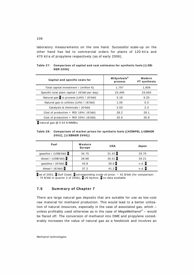
106
Methanol technologies
laboratory measurements on the one hand. Successful scale-up on the other hand has led to commercial orders for plants of 120 kt/a and 470 kt/a of propylene respectively (as of early 2006).
Table 27: Comparison of capital and cost estimates for synthetic fuels [LIEB-NER 2006]
Capital and specific costs for MtSynfuels® process
Modern FT synthesis
Total capital investment / (million €) 1,797 1,809
Specific total plant capital / (€/bbl per day) 23,490 23,650
Natural gas 1 to process (LHV) / (€/bbl) 5.18 6.25
Natural gas to utilities (LHV) / (€/bbl) 1.06 0.3
Catalysts & chemicals / (€/bbl) 2.63 2.3
Cost of production + ROI 16%/ (€/bbl) 28.2 28.1
Cost of production + ROI 25%/ (€/bbl) 35.9 35.8
1 natural gas @ 0.54 €/MMBtu
Table 28: Comparison of market prices for synthetic fuels ([KÖMPEL LIEBNER 2002], [LIEBNER 2006])
Fuel Western Europe
USA Japan
gasoline / (US$/bbl) 1 34.75 31.42 2 29.70
diesel / (US$/bbl) 1 28.88 26.51 2 33.21
gasoline / (€/bbl) 3 43.8 39.6 4 n.d. 5
diesel / (€/bbl) 3 37.2 41.2 4 n.d. 5
1 as of 2001; 2 Gulf Coast; 3 corresponding crude oil price: ~ 42 $/bbl (for comparison: ~ 70 $/bbl in quarter 2 of 2006); 4 US Nymex; 5 no data available
7.5 Summary of Chapter 7
There are large natural gas deposits that are suitable for use as low-cost raw material for methanol production. This would lead to a better utiliza-tion of natural resources, especially in the case of associated gas, which – unless profitably used otherwise as in the case of MegaMethanol® – would be flared off. The conversion of methanol into DME and propylene consid-erably increases the value of natural gas as a feedstock and involves an
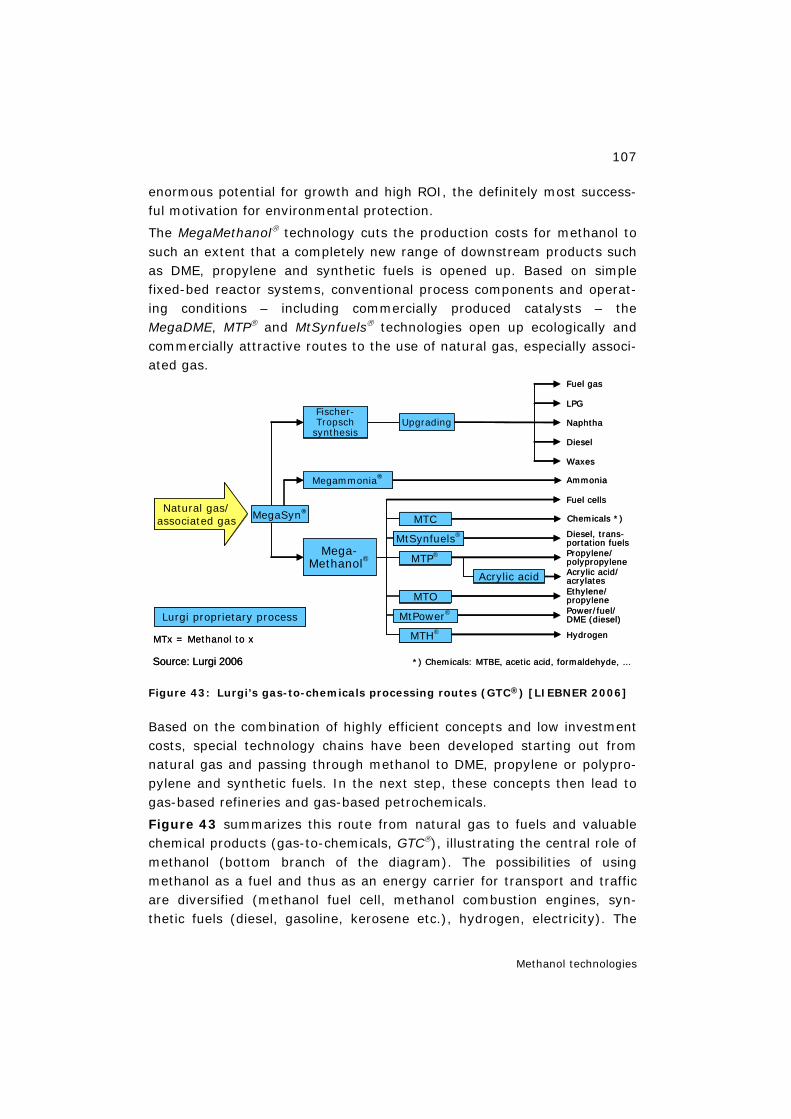
107
Methanol technologies
enormous potential for growth and high ROI, the definitely most success-ful motivation for environmental protection.
The MegaMethanol® technology cuts the production costs for methanol to such an extent that a completely new range of downstream products such as DME, propylene and synthetic fuels is opened up. Based on simple fixed-bed reactor systems, conventional process components and operat-ing conditions – including commercially produced catalysts – the MegaDME, MTP® and MtSynfuels® technologies open up ecologically and commercially attractive routes to the use of natural gas, especially associ-ated gas.
Figure 43: Lurgi’s gas-to-chemicals processing routes (GTC®) [LIEBNER 2006]
Based on the combination of highly efficient concepts and low investment costs, special technology chains have been developed starting out from natural gas and passing through methanol to DME, propylene or polypro-pylene and synthetic fuels. In the next step, these concepts then lead to gas-based refineries and gas-based petrochemicals.
Figure 43 summarizes this route from natural gas to fuels and valuable chemical products (gas-to-chemicals, GTC®), illustrating the central role of methanol (bottom branch of the diagram). The possibilities of using methanol as a fuel and thus as an energy carrier for transport and traffic are diversified (methanol fuel cell, methanol combustion engines, syn-thetic fuels (diesel, gasoline, kerosene etc.), hydrogen, electricity). The
Diesel, trans-portation fuels
Fuel gas
LPG
Naphtha
Diesel
Waxes
Ammonia
Fuel cells
Propylene/polypropyleneAcrylic acid/acrylatesEthylene/propylenePower/fuel/DME (diesel)
Hydrogen
Acrylic acid
MTC
MtSynfuels®
MTP®
MtPower®
MTH®
Upgrading
Mega-Methanol®
Megammonia®
Fischer-Tropsch
synthesis
MegaSyn®Natural gas/associated gas
MTx = Methanol to x
Chemicals *)
Source: Lurgi 2006 *) Chemicals: MTBE, acetic acid, formaldehyde, …
Lurgi proprietary process
MTO

108
Methanol technologies
additional new development of the use of methanol as a feedstock for the petrochemical industry could also produce synergy effects. Due to a fur-ther reduction in production costs and independence of the oil price and the associated fluctuations, methanol production on a large technical scale worldwide would make the use of methanol as a fuel even more attractive because of permanently low methanol prices.
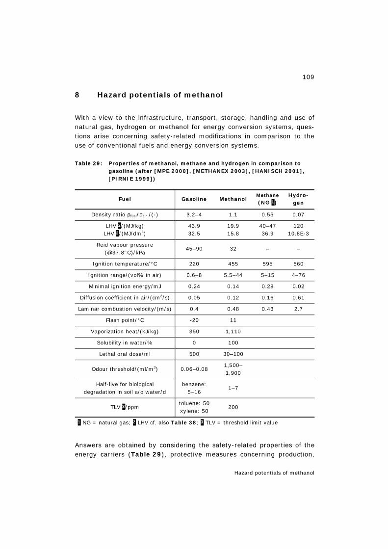
109
Hazard potentials of methanol
8 Hazard potentials of methanol
With a view to the infrastructure, transport, storage, handling and use of natural gas, hydrogen or methanol for energy conversion systems, ques-tions arise concerning safety-related modifications in comparison to the use of conventional fuels and energy conversion systems.
Table 29: Properties of methanol, methane and hydrogen in comparison to gasoline (after [MPE 2000], [METHANEX 2003], [HANISCH 2001], [PIRNIE 1999])
Fuel Gasoline Methanol Methane
(NG 1) Hydro-
gen
Density ratio ρfuel/ρair /(-) 3.2–4 1.1 0.55 0.07
LHV 2/(MJ/kg) LHV 2/(MJ/dm3)
43.9 32.5
19.9 15.8
40–47 36.9
120 10.8E-3
Reid vapour pressure (@37.8°C)/kPa
45–90 32 – –
Ignition temperature/°C 220 455 595 560
Ignition range/(vol% in air) 0.6–8 5.5–44 5–15 4–76
Minimal ignition energy/mJ 0.24 0.14 0.28 0.02
Diffusion coefficient in air/(cm2/s) 0.05 0.12 0.16 0.61
Laminar combustion velocity/(m/s) 0.4 0.48 0.43 2.7
Flash point/°C -20 11
Vaporization heat/(kJ/kg) 350 1,110
Solubility in water/% 0 100
Lethal oral dose/ml 500 30–100
Odour threshold/(ml/m3) 0.06–0.08 1,500–1,900
Half-live for biological degradation in soil a/o water/d
benzene: 5–16
1–7
TLV 3/ppm toluene: 50 xylene: 50
200
1 NG = natural gas; 2 LHV cf. also Table 38; 3 TLV = threshold limit value
Answers are obtained by considering the safety-related properties of the energy carriers (Table 29), protective measures concerning production,
110
Hazard potentials of methanol
transport, storage and system integration (e.g. in vehicles or CHP pack-ages) and operating instructions for the customer.
The hazard potential of methanol essentially concerns the areas of safety, environment, health and filling stations, for which statements after [HA-NISCH 1985], [HANISCH 2001], [WHO 1997] and [MFCA 2003] are sum-marized in the following.
8.1 Safety
Methanol is a physically and chemically well-defined substance, which has been produced for decades on a large technical scale and does not present any serious problem as far as the technology is concerned.
The odour threshold for methanol is high; a reduction by adding odorous and flavouring substances is conceivable (a Californian regulation already requires such additives). However, the compatibility of these additives must be ensured for heterogeneously catalysed methanol reforming [XCELLSIS 2002].
Methanol vapour is slightly heavier than air; explosive mixture can form with air. Due to the lower vapour pressure in comparison to gasoline, ig-nitable mixtures may form in the tank, so that closed refuelling systems and an adapted safety technology should be provided. The customer must not get into contact with methanol during fill-up. According to the present state of the art, refuelling could be performed in closed systems [MFCA 2003], [IDENTIC 2000].
The fire hazard is lower for methanol than for gasoline [MFCA 2003]. This is due to the lower volatility, higher ignition temperature, lower heating value and higher vaporization enthalpy of methanol. Fire-extinguishing powders and CO2 are used for small fires and AFFF foam for major fires.
Methanol is a colourless, volatile and highly flammable liquid with a typical smell. The flame visibility is comparable to that of hydrogen, slightly blu-ish, not visible in bright sunlight. In case of a fire, however, the flame is visible because other substances also burn [METHANEX 2003]. Californian regulations for handling methanol (M100) do not prescribe any additives to the methanol for making the flame visible, but an on-board flame ar-rester to prevent flashback [XCELLSIS 2002].
The use of methanol in road traffic would double the deployment of tank-ers on the roads due to the about 50% lower volume-related heating value compared to gasoline/diesel (Table 25) and thus increase the num-
111
Hazard potentials of methanol
ber of tanker accidents assuming the same frequency. Compared to gaso-line, however, the fire hazard would be lower.
8.2 Environmental impacts due to leakages
Methanol is degradable in the environment due to processes of photooxi-dation and biodegradation; in soil some microorganisms can take up methanol for growth and degrade it to water and carbon dioxide.
In the case of small leakages, methanol has only a minor toxic effect on waters and soils. In soil methanol is more readily degradable than gaso-line. High concentrations of methanol make biodegradation in waters and soils increasingly difficult. Concerning the volatility of methanol from wa-ter cf. Henry coefficient (Chapter 14.2.2 and Table 36).
The lethal methanol dose, LD50, for 50% of a population of rats, mice and dogs examined is in the range of 6,200–13,000 mgmethanol/kgbody weight [WHO 1997]. For freshwater fish the LD50 value of methanol is 13,000–29,000 mgmethanol/lwater for an exposure of 96 h. It is thus clearly higher than for a corresponding exposure to gasoline [WHO 1997], [MFCA 2003].
8.3 Human health
Humans are endangered by the oral or inhalative uptake of methanol es-pecially during refuelling. Additives to methanol, which increase the taste and odour thresholds, as well as closed refuelling systems can minimize this danger.
Of medical relevance is above all the miscibility of methanol with water and organic compounds, which is possible in any ratio, as well as the sol-vent power in fat, although this is low. Methanol can be contained in die-tetic food and soft drinks via the artificial sweetener ASPARTAM [WHO 1997].
The toxicokinetics of methanol is known. Oxidative processes produce formaldehyde and formic acid as the actually toxic metabolite. Methanol has a slightly irritant effect if taken up via the skin, eyes and respiratory system. Depending on the dose, the oral and inhalative uptake of metha-nol can lead to blindness (above 5–15 ml) or death (above 30–100 ml). A complete healing of possible poisoning effects is possible if established methods of treatment are applied rigorously and in time. There are no clues for any carcinogenic, mutagenic or teratogenic effect.
112
Hazard potentials of methanol
8.4 Filling stations
In connection with a BMFT research project from the eighties on alcohol fuels, the German Committee on burnable fluids (DabF) made a safety-related statement in 1980 [HANISCH 2001], according to which DabF has no safety-related objections to the construction of filling stations for methanol fuel, provided that the applicable regulations are complied with. According to the present state of the art, refuelling could be performed in closed systems [IDENTIC 2000] and [MFCA 2003].
The requirements to be fulfilled by materials used in fuel systems (metals and elastomers) with respect to their resistance to methanol are well known and imply a corresponding expenditure on building up a suitable supply network [HANISCH 2001].
If used in accordance with regulations and if all relevant rules are ob-served, handling methanol does not represent any health or safety prob-lem [HOMMEL 1997], [EU 1991].
8.5 Comparison with possible direct fuel cell fuels
The acute toxicity of methanol is often cited as a disadvantage. However, it is much less toxic than gasoline as the established energy carrier which we are used to handle today. In contrast to methanol, gasoline is also car-cinogenic and teratogenic. Methanol is much more easily biodegradable than gasoline or diesel. Due to its solubility in water, methanol can pene-trate through the skin into the human body during handling, but this can be prevented by protective measures. Table 30 shows a comparison of the properties and suitability of alternative energy carriers, especially methanol, with hydrogen and gasoline, all of which are in principle possi-ble energy carriers for use in direct fuel cells. Methanol comes off best in this comparison [HEINZEL et al. 2006].
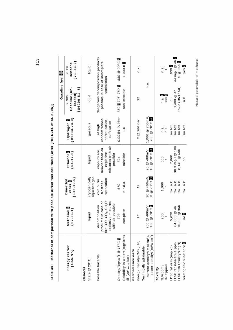
113
Haz
ard p
oten
tial
s of
met
han
ol
Tab
le 3
0:
M
eth
an
ol in
co
mp
ari
son
wit
h p
oss
ible
dir
ect
fu
el ce
ll f
uels
(aft
er
[HEIN
ZEL e
t al.
20
06
])
Gaso
lin
e f
uel
5 a
En
erg
y c
arr
ier
{C
AS
-Nr.
}
Meth
an
ol
1
{6
7-5
6-1
}
Dim
eth
yl
eth
er
2
{1
15
-10
-6}
Eth
an
ol
3
{6
4-1
7-5
}
Hyd
rog
en
4
{0
13
33
-74
-0}
> 9
0%
G
aso
lin
e (
un
-le
ad
ed
) {
86
29
0-8
1–
5}
< 1
%
Ben
zen
e
{7
1–
43
-2}
GGeenn
eerr aa
ll
Sta
te @
20°C
liq
uid
cr
yogen
ical
ly
liquef
ied g
as
liquid
gas
eous
liquid
liq
uid
Poss
ible
haz
ards
dec
om
posi
tion
pro
duct
s in
cas
e of
fire
: CO
, CO
2,
CH
2O
; ex
plo
sive
mix
ture
s w
ith a
ir p
ossi
ble
cold
burn
/ fr
ost
bite,
su
ffoca
tion
vapours
are
hea
vier
than
air;
explo
sive
m
ixtu
res
with a
ir
pos
sible
at h
igh
conce
ntr
atio
ns:
nar
cotiza
tion
, su
ffoca
tion
dan
ger
ous
dec
om
posi
tion p
roduct
s poss
ible
in c
ase
of in
com
ple
te
com
bust
ion
Den
sity
/(kg
/m3)
@ 1
5°C
6
793
670
794
0.0
9@
1.0
13bar
750 6
,725–780 5
880 @
20°C
7
Sol
ubili
ty in w
ater
/(m
g/l
itre
) @
(20°C
, 1 b
ar)
co
mple
te
n.r
.d.a
. m
isci
ble
1.6
non
-mis
cible
1,0
00.8
7
PPeerr ff
oorr mm
aann
ccee dd
aatt aa
Ener
gy
den
sity
/(M
J/l)
[6]
16
19
21
3 @
300 b
ar
32
n.k
.
Tec
hnic
ally
att
ainab
le
curr
ent
den
sity
/(m
A/c
m2),
pow
er d
ensi
ty/(
mW
/cm
2)
250 @
400m
V,
100 @
70°C
9
20 @
400m
V,
8 @
70°C
10
25 @
400m
V,
10 @
70°C
11
1,0
00 @
700m
V,
700 @
70°C
12
n.a
.
TTooxxii cc
ii ttyy
TLV
/ppm
v TRC/p
pm
v 200
./.
1,0
00
./.
500
./.
n.a
. n.a
. n.a
. b
300 c
n.a
. 1
LD50 r
at o
ral/
(mg/k
g)
LC50 r
at inhal
ativ
e/ppm
LC
50 fis
h t
oxic
ity/
(mg/l
)
5,6
28
64,0
00 @
4h
10,8
00 @
96h
tox.
n.k
. to
x. n
.k.
tox.
n.k
.
7,0
60
38.3
mg/l
@ 1
0h
8,1
40 @
48h
no t
ox.
no t
ox.
no t
ox.
n.i.
3,4
00 @
4h
toxi
c (R
51
/5
3)
930 7
44 m
g/l
@ 4
h 7
5 @
96h 7
Ter
atogen
ic s
ubst
ance
d
no 8
to
x. n
.k.
no
no t
ox.
n.k
. ye
s 7
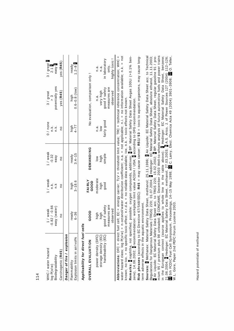
114
Haz
ard p
oten
tial
s of
met
han
ol
WH
C /
wat
er h
azar
d
log P
(o/w
) Bio
deg
radab
ility
1 /
wea
k -0
.82 /
-0.6
6
easy
(w
ater
)
1 /
wea
k n.k
. n.k
1 /
wea
k -0
.32
easy
0 /
none
n.k
. n.k
.
3 /
gre
at
> 3
pot
ential
ly y
es
3 /
gre
at 7
2.1
7
easy
7
Car
cinog
enic
(R
45
) no
no
no
no
yes
(R4
5)
yes
(R4
5)
DDaann
ggeerr
ooff
ff iirr ee
// ee
xxpp
ll oossii oo
nn
Flam
mab
ility
Exp
losi
on lim
its
in a
ir/v
ol%
re
ady
6–36
hig
h
3–18.6
re
ady
3.4
–15
hig
h
4–77
hig
h
0.6
–0.8
(lo
w)
read
y
1.2
–8 7
AApp
ppll iiccaabb
ii llii tt
yy ff
oorr
ddii rr
eecctt
ff uueell cceell llss
OV
ER
ALL E
VA
LU
ATIO
N
GO
OD
FA
IRLY
G
OO
D
DEM
AN
DIN
G
No e
valu
atio
n,
com
par
ison o
nly
!
pow
er d
ensi
ty (
DFC
) st
ora
ge
den
sity
(EC)
han
dle
abili
ty (
EC)
hig
h
hig
h
good if
safe
ty
mea
sure
s ar
e ob
serv
ed
mod
erat
e hig
h
goo
d
low
hig
h
sim
ple
n.a
. lo
w
fairly
goo
d
n.a
. ve
ry h
igh
good if
safe
ty
mea
sure
s ar
e ob
serv
ed
n.a
. n.a
. in
lab
orat
ory
only
, hig
hly
toxi
c !
Ab
bre
via
tio
ns:
DFC
= d
irec
t fu
el c
ell;
EC =
ener
gy
carr
ier;
TLV
= t
hre
shold
lim
it v
alue;
TRC =
tec
hnic
al r
efer
ence
conce
ntr
atio
n;
WH
C =
w
ater
haz
ard c
lass
; lo
g P
(o/w
) =
n-o
ctan
ol/
wat
er d
istr
ibution c
oef
fici
ent;
n.a
. =
not
applic
able
; n.i.
= n
o in
form
atio
n a
vaila
ble
; n.k
. =
not
kn
ow
n;
no t
ox.
= n
o s
pec
ific
toxi
c ef
fect
; n.r
.d.a
. =
no r
elia
ble
dat
a av
aila
ble
; to
x. n
.k.
= t
oxi
c ef
fect
s not
know
n.
R
em
ark
s: a
nap
hth
a, n
ot s
pec
ifie
d;
pos
sible
: oxy
gen
com
pounds,
additiv
es;
b B
P: M
ater
ial Saf
ety
Dat
a Shee
t Avg
as 1
00LI
(>
0.1
% b
en-
zene)
, 14.0
6.2
002;
c re
com
men
dat
ion:
wor
kpla
ce lim
it v
alue
ACG
IH /
USA;
d a
ccor
din
g t
o D
FG r
ecom
men
dat
ion.
R
isk p
hra
ses
(acc
ord
ing t
o EC D
irec
tive
67/5
48/E
EC):
R4
5 =
may
cau
se c
ance
r; R
51
/5
3 =
tox
ic t
o a
quat
ic o
rgan
ism
s, m
ay c
ause
lon
g-
term
adve
rse
effe
cts
in t
he
aquat
ic e
nvi
ronm
ent.
S
ou
rces:
1 M
ethan
ex:
Mat
eria
l Saf
ety
Dat
a Shee
t, m
ethan
ol;
25.1
1.1
996;
2 A
ir L
iquid
e: E
C M
ater
ial Saf
ety
Dat
a Shee
t ac
c. t
o Tec
hnic
al
Reg
ula
tions
for
Dan
ger
ous
Mat
eria
ls (
TRG
S)
220;
01.0
7.2
004;
3 H
edin
ger
: EC M
ater
ial Saf
ety
Dat
a Shee
t, a
bso
lute
eth
anol, 1
1.1
1.2
003;
4 A
ir L
iquid
e: E
C M
ater
ial Saf
ety
Dat
a Shee
t ac
c. t
o TRG
S 2
20;
15.0
2.2
002;
5 B
P: M
ater
ial Saf
ety
Dat
a Shee
t, r
egula
r gas
olin
e 91 /
pre
-m
ium
95 /
pre
miu
m p
lus
98 u
nle
aded
; 6 C
ON
CAW
E,
Dec
ember
2003 W
ell-
to-w
hee
ls a
nal
ysis
of
futu
re a
uto
mot
ive
fuel
s an
d p
ower
tra
ins
in th
e Euro
pea
n co
nte
xt (s
ourc
e ap
plie
s to
w
hol
e lin
e in
th
e ta
ble
ab
ove)
; 7 H
edin
ger
: EC M
ater
ial
Saf
ety
Dat
a Shee
t, ben
zene;
21.0
6.2
004;
8 H
edin
ger
: EC M
ater
ial
Saf
ety
Dat
a Shee
t, m
ethan
ol;
27.0
3.2
003;
9 A
.S.
Arico
, J.
of
Pow
er S
ourc
es 1
27 (
2004)
112–126;
10 5
th F
CD
IC F
uel
Cel
l Sym
pos
ium
, Pr
ocee
din
gs,
14–15 M
ay 1
998;
11 C
. La
my,
Ele
ct.
Chem
ica
Act
a 49 (
2004)
3901–3908;
12 O
. Tel
ler,
W
.L.
Gore
, Pa
per
2nd P
EFC
Foru
m L
uce
rne
2003.
115
Hazard potentials of methanol
8.6 Summary of Chapter 8
If used in accordance with regulations and if all relevant rules are ob-served, handling methanol does not represent any health or safety prob-lem. The use of methanol in road traffic would double the deployment of tankers on the roads due to the about 50% lower volume-related heating value compared to gasoline/diesel and thus increase the number of tanker accidents assuming the same frequency. Compared to gasoline, however, the fire hazard would be lower. Humans are endangered by the oral or in-halative uptake of methanol especially during refuelling. Additives to methanol, which increase the taste and odour thresholds, as well as closed refuelling systems can minimize this danger.
The acute toxicity of methanol is often cited as a disadvantage. However, it is much less toxic than gasoline as the established energy carrier which we are used to handle today.
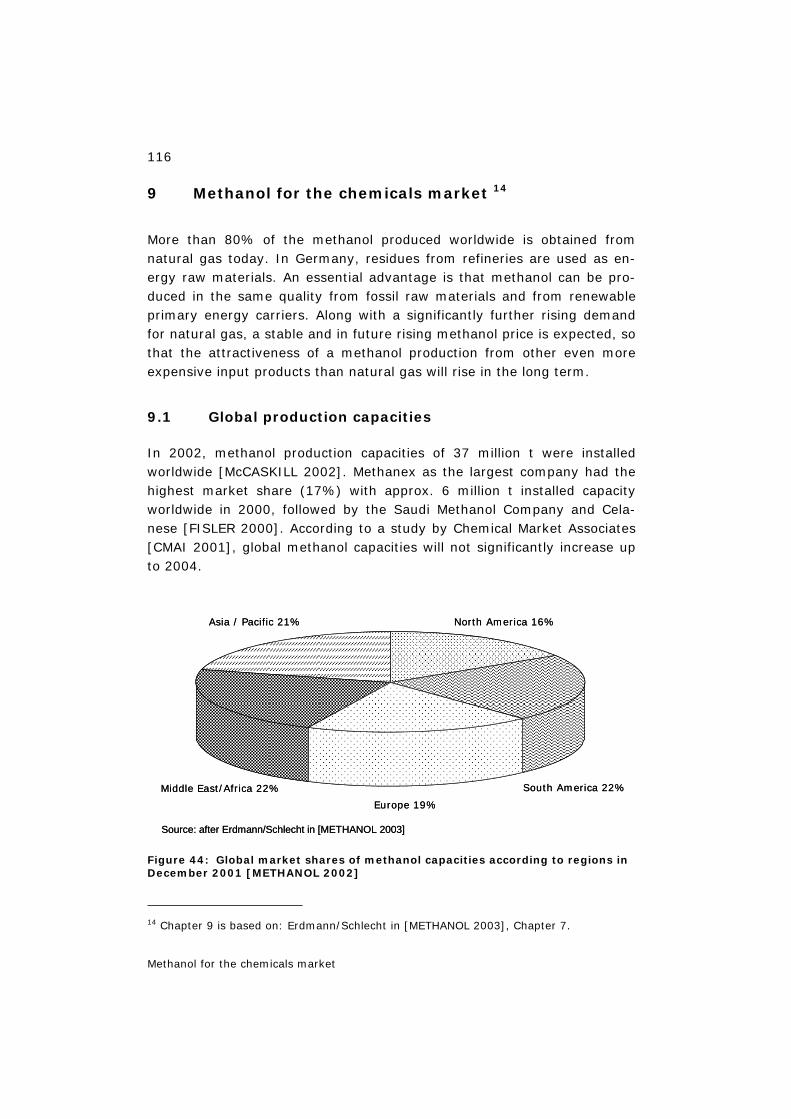
116
Methanol for the chemicals market
9 Methanol for the chemicals market 14
More than 80% of the methanol produced worldwide is obtained from natural gas today. In Germany, residues from refineries are used as en-ergy raw materials. An essential advantage is that methanol can be pro-duced in the same quality from fossil raw materials and from renewable primary energy carriers. Along with a significantly further rising demand for natural gas, a stable and in future rising methanol price is expected, so that the attractiveness of a methanol production from other even more expensive input products than natural gas will rise in the long term.
9.1 Global production capacities
In 2002, methanol production capacities of 37 million t were installed worldwide [McCASKILL 2002]. Methanex as the largest company had the highest market share (17%) with approx. 6 million t installed capacity worldwide in 2000, followed by the Saudi Methanol Company and Cela-nese [FISLER 2000]. According to a study by Chemical Market Associates [CMAI 2001], global methanol capacities will not significantly increase up to 2004.
Figure 44: Global market shares of methanol capacities according to regions in December 2001 [METHANOL 2002]
14 Chapter 9 is based on: Erdmann/Schlecht in [METHANOL 2003], Chapter 7.
North America 16%
South America 22%
Europe 19%
Middle East/Africa 22%
Asia / Pacific 21%
Source: after Erdmann/Schlecht in [METHANOL 2003]
North America 16%
South America 22%
Europe 19%
Middle East/Africa 22%
Asia / Pacific 21%
Source: after Erdmann/Schlecht in [METHANOL 2003]
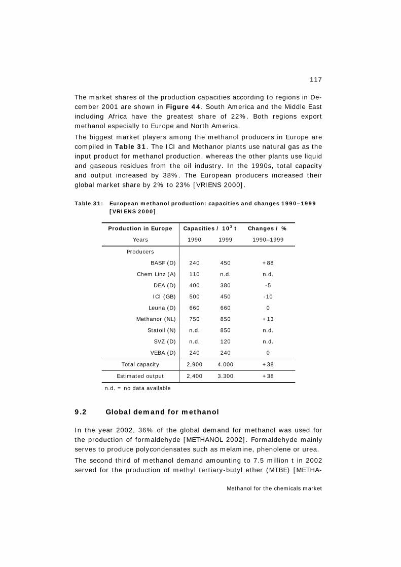
117
Methanol for the chemicals market
The market shares of the production capacities according to regions in De-cember 2001 are shown in Figure 44. South America and the Middle East including Africa have the greatest share of 22%. Both regions export methanol especially to Europe and North America.
The biggest market players among the methanol producers in Europe are compiled in Table 31. The ICI and Methanor plants use natural gas as the input product for methanol production, whereas the other plants use liquid and gaseous residues from the oil industry. In the 1990s, total capacity and output increased by 38%. The European producers increased their global market share by 2% to 23% [VRIENS 2000].
Table 31: European methanol production: capacities and changes 1990–1999 [VRIENS 2000]
Production in Europe Capacities / 103 t Changes / %
Years 1990 1999 1990–1999
Producers
BASF (D) 240 450 +88
Chem Linz (A) 110 n.d. n.d.
DEA (D) 400 380 -5
ICI (GB) 500 450 -10
Leuna (D) 660 660 0
Methanor (NL) 750 850 +13
Statoil (N) n.d. 850 n.d.
SVZ (D) n.d. 120 n.d.
VEBA (D) 240 240 0
Total capacity 2,900 4.000 +38
Estimated output 2,400 3.300 +38
n.d. = no data available
9.2 Global demand for methanol
In the year 2002, 36% of the global demand for methanol was used for the production of formaldehyde [METHANOL 2002]. Formaldehyde mainly serves to produce polycondensates such as melamine, phenolene or urea.
The second third of methanol demand amounting to 7.5 million t in 2002 served for the production of methyl tertiary-butyl ether (MTBE) [METHA-
118
Methanol for the chemicals market
NOL 2002]. Instead of the formerly used organic lead compounds, MTBE is admixed to gasoline fuels as an anti-knocking agent. 57% of the global MTBE demand was needed by the USA in the year 2000. In the same year, the United States imported 30% of the global MTBE production. Cali-fornia alone claimed 20% of the global MTBE demand in 2000. 43% of the installed MTBE production capacities worldwide were located in the USA in 2000, the remainder was covered by imports especially from the Middle East, Canada and Venezuela. Until recently MTBE essentially contributed to the growth of the methanol market [FISLER 2000].
With the introduction of the 1990 Clean Air Act Amendments the year-round use of reformulated gasoline (RFG) is required in cities with great summer smog problems. On balance, reformulated gasoline produces fewer emissions of ozone-forming and toxic air pollutants with the same fuel throughput as conventional gasoline. This fuel contains a fraction of at least 2wt% (or 11vol%) of chemically bound oxygen (oxygenate), which is obtained with the aid of MTBE [DOE 2003] (for comparison, most of the fuels used in Germany contain clearly less MTBE than the Californian fu-els).
Due to the lack of storage regulations for fuels, pipeline and tank leakages are nothing unusual in the USA. Major MTBE contaminations in groundwa-ter already occurred there in the mid-nineties. Only after the introduction of reformulated gasoline with an MTBE fraction of 11vol% was it recog-nized that MTBE is poorly degradable and very mobile in soil. The addition of MTBE to reformulated gasoline has been prohibited in California since the end of 2003 (cf. Chapter 11.2).
7% of the methanol produced worldwide was used for the production of acetic acid in 2002. This mainly served as the base product for various acetic acid esters: as a monomer for vinyl acetate and as cellulose acetate in artificial silk production. Furthermore, acetic acid finds application as a solvent for lacquers and resins, in inorganic salts as an additive in the clothing industry, in dye works and in medicine.
3% of the methanol produced worldwide was further processed to methyl methacrylate (MMA) in the same year. MMA is used in chemical production as a monomer for the fabrication of acryl glass. Another methanol fraction of approx. 2% was used for the production of dimethyl terephthalate (DMT). DMT is used, in particular, for the production of polycondensates, above all polyethylene terephthalate (PET).
Approx. 20% of the methanol produced worldwide in 2002 covered the demand in various fields of application [METHANOL 2002].
119
Methanol for the chemicals market
In 1999 in Western Europe 49.5% of the methanol was used for formal-dehyde production. Another 16.5% was used in MTBE production [VRIENS 2000]. According to the Commission of the European Union (EU) there is no need for action concerning the replacement of MTBE in gasoline fuel. Unlike the American legal requirements for fuel, the EU fuel directive does not stipulate minimum values for MTBE, but a maximum oxygen content [EU 1998]. The Danish government pushes the replacement of this fuel additive by imposing a tax of 0.67 €/l on MTBE [T&E 2000].
9.3 Prospects for global methanol demand
The determining factor for methanol demand is the sales development in the chemical industry. The economic development in the chemical sector follows the gross national product (GNP) [HOPP 2001]. The GNP is a na-tional economy indicator for the development of markets and it character-izes the value of all goods and services having a market price and being consumed, invested or exported by citizens during a defined period. The GNP is reduced by the value of all imported goods and services. GNP growth can thus be transferred to methanol sales and thus to the demand for methanol.
However, the production of acetic acid grows more strongly than the GNP. The demand for methanol rises correspondingly faster in this segment. This may be due to the fact that a technology shift from ethylene (oxida-tion of ethylene or of acetaldehyde from ethylene [WACKER 2003]) to methanol (methanol carbonylation [CELANESE 2003]) as the base product for acetic acid production has taken place in recent decades [McCASKILL 2000].
If the ban on MTBE15 is enforced in California, 20% of the MTBE demand will break away worldwide. This will affect, in particular, sites with high production costs in the USA. Should these production capacities not be shut down, their production will press as MTBE exports on the world mar-ket, which would probably result in a global price decline for MTBE. Irre-spective of this, a cost-induced decrease of production capacities is al-ready to be expected in North America in the medium term. Chemical Market Associates (CMAI) expect that two thirds of the methanol capaci-ties in the USA will be cut down by 2005 [FISLER 2000]. However, new production facilities are being built in South America, Africa and the Middle
15 cf. Chapter 11.2
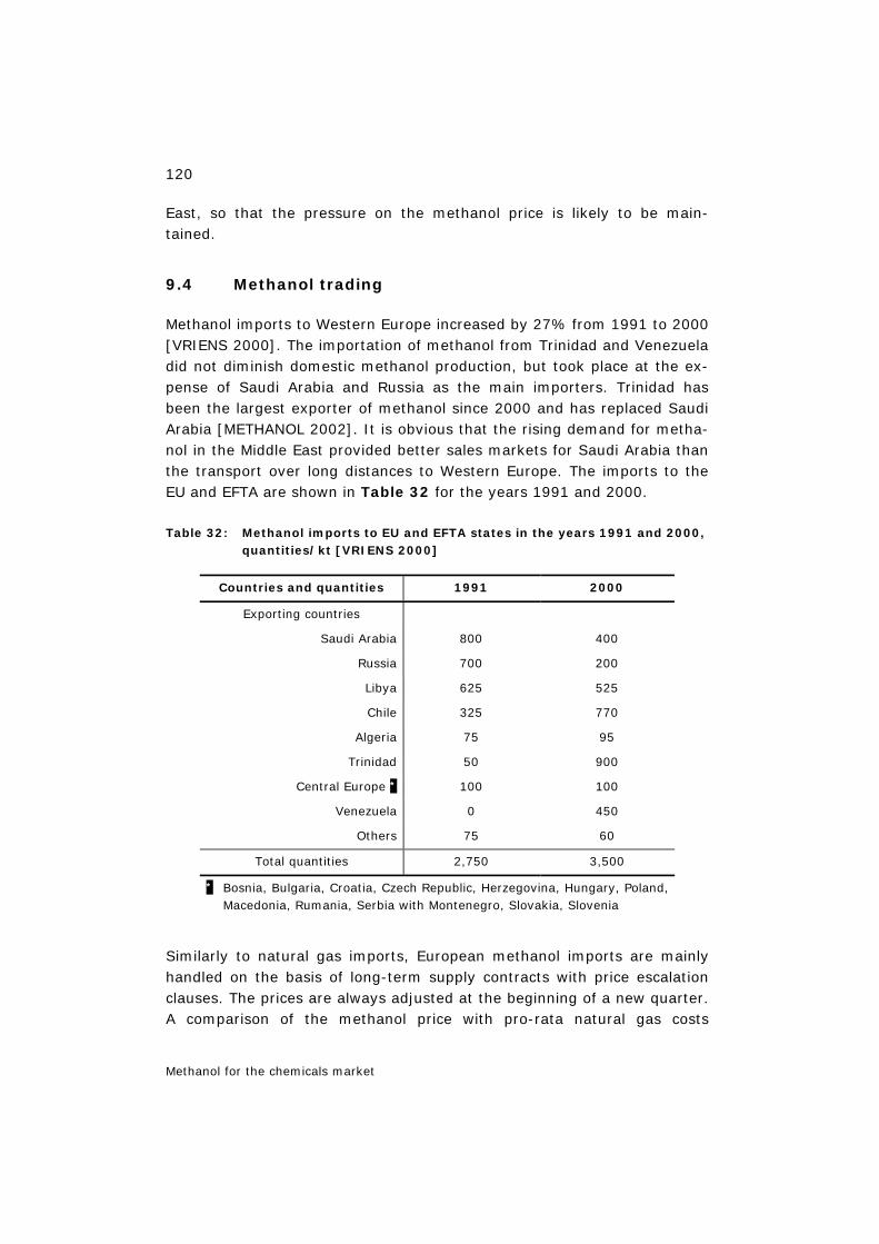
120
Methanol for the chemicals market
East, so that the pressure on the methanol price is likely to be main-tained.
9.4 Methanol trading
Methanol imports to Western Europe increased by 27% from 1991 to 2000 [VRIENS 2000]. The importation of methanol from Trinidad and Venezuela did not diminish domestic methanol production, but took place at the ex-pense of Saudi Arabia and Russia as the main importers. Trinidad has been the largest exporter of methanol since 2000 and has replaced Saudi Arabia [METHANOL 2002]. It is obvious that the rising demand for metha-nol in the Middle East provided better sales markets for Saudi Arabia than the transport over long distances to Western Europe. The imports to the EU and EFTA are shown in Table 32 for the years 1991 and 2000.
Table 32: Methanol imports to EU and EFTA states in the years 1991 and 2000, quantities/kt [VRIENS 2000]
Countries and quantities 1991 2000
Exporting countries
Saudi Arabia 800 400
Russia 700 200
Libya 625 525
Chile 325 770
Algeria 75 95
Trinidad 50 900
Central Europe * 100 100
Venezuela 0 450
Others 75 60
Total quantities 2,750 3,500
* Bosnia, Bulgaria, Croatia, Czech Republic, Herzegovina, Hungary, Poland, Macedonia, Rumania, Serbia with Montenegro, Slovakia, Slovenia
Similarly to natural gas imports, European methanol imports are mainly handled on the basis of long-term supply contracts with price escalation clauses. The prices are always adjusted at the beginning of a new quarter. A comparison of the methanol price with pro-rata natural gas costs
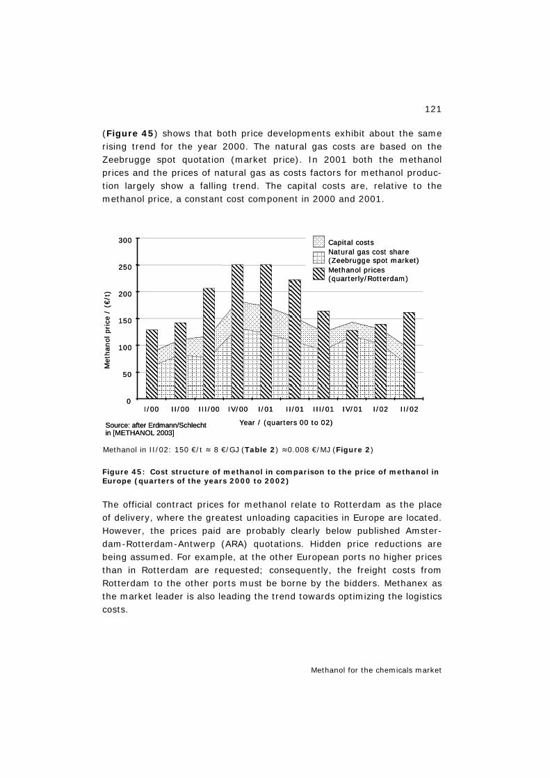
121
Methanol for the chemicals market
(Figure 45) shows that both price developments exhibit about the same rising trend for the year 2000. The natural gas costs are based on the Zeebrugge spot quotation (market price). In 2001 both the methanol prices and the prices of natural gas as costs factors for methanol produc-tion largely show a falling trend. The capital costs are, relative to the methanol price, a constant cost component in 2000 and 2001.
Methanol in II/02: 150 €/t ≈ 8 €/GJ (Table 2) ≈0.008 €/MJ (Figure 2)
Figure 45: Cost structure of methanol in comparison to the price of methanol in Europe (quarters of the years 2000 to 2002)
The official contract prices for methanol relate to Rotterdam as the place of delivery, where the greatest unloading capacities in Europe are located. However, the prices paid are probably clearly below published Amster-dam-Rotterdam-Antwerp (ARA) quotations. Hidden price reductions are being assumed. For example, at the other European ports no higher prices than in Rotterdam are requested; consequently, the freight costs from Rotterdam to the other ports must be borne by the bidders. Methanex as the market leader is also leading the trend towards optimizing the logistics costs.
0
50
100
150
200
250
300
I/00 II/00 III/00 IV/00 I/01 II/01 III/01 IV/01 I/02 II/02
Met
hanol
pri
ce/
(€/t
)
Capital costsNatural gas cost share(Zeebrugge spot market)Methanol prices(quarterly/Rotterdam)
Year / (quarters 00 to 02)Source: after Erdmann/Schlechtin [METHANOL 2003]
0
50
100
150
200
250
300
I/00 II/00 III/00 IV/00 I/01 II/01 III/01 IV/01 I/02 II/02
Met
hanol
pri
ce/
(€/t
)
Capital costsNatural gas cost share(Zeebrugge spot market)Methanol prices(quarterly/Rotterdam)
Year / (quarters 00 to 02)Source: after Erdmann/Schlechtin [METHANOL 2003]
122
Methanol for the chemicals market
9.5 Methanol prices
There are numerous processes for the production of methanol. Each of these processes can be profitable under the respective production condi-tions such as capacity, availability, process type and costs of primary products, consumables and synergy potential.
The optimum conditions for low methanol production costs are:
– low costs of the feedstock to be used, often natural gas,
– high synthesis gas production capacities and yields,
– high synergy potential for the production of byproducts.
Methanol production plants exhibit significant economics of scale. These are understood to be decreasing unit costs with increasing production. Reasons for economics of scale are:
– more efficient production due to larger plants,
– use of improved production processes,
– degression of fixed costs per output unit with rising output,
– better purchasing conditions,
– learning effects.
Thus, the production costs, for example, for tandem reforming (two-stage reforming with oxygen import in the second stage) amount to more than 115 US$/t for production capacities of <1,000 t/d and decrease to 80 US$/t for production capacities of 3,000 t/d (in comparison, for steam reforming: >140 US$/t and approx. 100 US$/t for production capacities of <1,000 t/d and 3,000 t/d, respectively; approx. 105 US$/t for 2,500 t/d) [MICHEL 1999].
The published prices for methanol FOB Rotterdam were 145 US$/t in April 2002. In comparison, the spot price on the American Gulf Coast was only 125 US$/t in March. In the Asian/Pacific region the price per ton was be-tween 132 and 147 US$. As for other energy carriers, the methanol prices were very unstable in the past two years. The price development in the year 2000 was determined by a loss of production capacities totalling 1.5 million t in the USA and Trinidad. Added to this were the high natural gas prices, which led to a methanol price of over 200 US$/t (1 US$/t≈1 €/t in Figure 45) in the last quarter of 2000 and thus to almost a doubling in comparison to the first quarter of 2000 [McCASKILL 2000]. In the course of the year 2001 the price dropped again to the level observed before. The causes include global economic slowdown and the already mentioned changes on the American market. A renewed price increase was recorded
123
Methanol for the chemicals market
in the first quarter of 2002. At the end of the same year, a price level of 200 US$/t was reached, which is likely to be maintained until mid-2003 [McCASKILL 2002].
Between 1985 and 1999 the methanol prices ranged between 100 and 200 US$/t with an average of 150 US$/t [MICHEL 1999]. The last cyclical price decline began in 1998 and was caused by an oversupply of metha-nol.
9.6 Future development
Methanol use in Europe is strongly focused on the chemicals market today [McCASKILL 2000]. Apart from the application as a fuel additive in the form of MTBE, methanol could also be directly used as a fuel for internal combustion engines or for fuel cell power trains. Another field of applica-tion could be the production of dimethyl ether as a substitute for diesel fuel, which would have the advantage of a particulate-free combustion in diesel combustion engines (cf. Chapter 3 and Chapter 7.2).
The plastics-processing industry could also be a conceivable market for enhanced methanol use. Propylene, an important petrochemical base ma-terial for plastics production, has so far almost exclusively been produced from oil.
With its methanol-to-propylene process LURGI has developed a new proc-ess up to market maturity, with which propylene is produced from metha-nol, which in turn is obtained from natural gas. In view of an expected in-crease in propylene demand LURGI sees excellent market opportunities [LURGI 2002].
The ban on MTBE16 discussed in the USA and initiated in California leads to an enormous pricing pressure on methanol as the primary product; LURGI therefore developed the MegaMethanol technology for production plants with capacities >1.5 million t/y. This reduces the specific investment costs. In view of the cost problems for the US methanol capacities, a con-tinuing capacity reduction is to be expected in the USA, which could elimi-nate the current problem of overcapacities.
From the European perspective, the future methanol price will be signifi-cantly influenced by the natural gas price, as in the past. In the event of a further deregulation of the European natural gas markets, the pressure on
16 cf. Chapter 11.2
124
Methanol for the chemicals market
the natural gas prices could continue to exist, especially in the market for bulk buyers of relevance here. But the impacts on the price level will re-main modest according to many analysts. In fact, the bulk buyer natural gas prices greatly depend on the import gas prices, and even if the previ-ous close price coupling to heating oil or heavy oil were replaced by other price formulae, a permanent decline in natural gas prices is not to be ex-pected due to the anticipated massive investments in European gas supply alone. Consequently, the methanol price in Europe will rise rather than drop below today's price level in the medium term. This will be the case, in particular, if an effective climate protection policy is adopted at least in Europe, since this will directly result in rising natural gas prices, because the European power plants will increasingly use natural gas as the fuel with lower CO2 emissions compared to coal for electricity production.
9.7 Summary of Chapter 9
The global development of the demand for methanol is assessed similarly among the experts. [McCASKILL 2002] assumes a continuous growth to 33 million t up to 2006, before there will be a decline in methanol demand to 31 million t in 2007 due to the American MTBE ban. In early 2008 he expects a renewed increase in methanol demand. [AL SAYED 2000] also assumes a global growth in demand of 2.2% for 1998 to 2004. A market study [RASCHKA 2003] shows that sales decline due to the ban on MTBE17 in the USA is overcompensated in the longer term by the increasing de-mand for methanol of the chemical industry in the Asian-Pacific region. Methanol could achieve a genuine breakthrough, if it were – also in com-petition with other alternative fuels – increasingly used as a fuel. How-ever, this is not perceivable at the moment. Therefore, the chemicals market will remain the most important growth and sales market for methanol for the time being.
17 cf. Chapter 11.2
125
Biofuel projects
10 Biofuel projects 18
In order to push the market launch of alternative fuels (natural gas, biofu-els and hydrogen), the EU plans to introduce 8% biogenic fuels (corre-sponding to about 30 million toe) into the fuel market, 10% natural gas and 5% hydrogen up to the year 2020 [EU 2000], [EU 2001]. The driving forces are the Kyoto targets for CO2 reduction and the decreasing depend-ence of the transport sector on crude oil imports. – See also [HEINLOTH 2002].
10.1 Overview
Theoretically, 8–14% of the agriculturally usable area in the EU is suffi-cient to reach the biofuel quota target. Another 8% would be needed if hydrogen were to be produced from biomass. At present, the set-aside area in the EU is about 6%. Additional important agricultural areas will be-come available due to the EU enlargement to the East. Waste materials and renewable electricity production represent an additional potential for biofuel and hydrogen production.
The resources of renewable energies for fuel production are sufficient to fulfil the political targets. The Transport Energy Strategy (TES) estimates the potential of biofuels (energy crops, waste and residual materials) at 15% of the total fuel demand of the 15 EU member states (EU15) (range 11–24%).
The basic processes for the production of renewable fuels have been in-vestigated and are known in principle. At present, research projects are being implemented to obtain reliable data on energy balances, emissions and costs and to evaluate optimum concepts for economical fuel produc-tion (decentralized biomass procurement, decentralized and centralized fuel production).
Methanol can be relatively easily produced from biomass and can be used both in internal combustion engines (in the form of a fuel blend without engine adaptation or as pure fuel with engine modification) and in fuel cell systems (with on-board methanol reforming for PEFCs or directly for DMFCs).
18 Chapter 10 is based on: Isenberg/Edinger in [METHANOL 2003], Chapter 8.
126
Biofuel projects
The EU targets concerning renewable fuels can be reached by the use of waste and residual materials for energy generation, of renewable electric-ity and of energy crops. The addition of renewable fuels to conventional gasoline or diesel does not require a new infrastructure during market in-troduction. Investments can be exclusively used for fuel production.
Demonstration projects will have to prove the environmental compatibility of renewable fuels, their availability, economic efficiency and suitability for use in vehicles in comparison to conventional fuels.
10.2 Production paths for biofuels
The use of fuels produced from renewable energy sources will be of in-creasing significance in the mobility sector. It may reduce traffic-related emissions, above all CO2. Future fuel supply can be assured by broadening the supply base, especially by domestic energy carriers [ISENBERG 2001].
Biomass is a promising resource for environmentally compatible fuel pro-duction. Various processes can be used to convert biomass into fuels:
– oil extraction from oil-containing plants,
– fermentation of waste materials and energy crops (e.g. biomass with high sugar or starch content) to biogas or alcohols, especially ethanol,
– gasification of biomass and subsequent fuel production by synthesis to alcohols (e.g. methanol), Fischer-Tropsch fuels (synthetic diesel and gasoline) or hydrogen separation from synthesis gases.
For example, biomethanol can be obtained by the gasification of biomass to synthesis gas and subsequent methanol synthesis. As in the production of methanol from natural gas, after the production of a synthesis gas (CO, CO2, H2) methanol is obtained here by a heterogeneously catalysed syn-thesis dissipating heat (cf. equation 4.2).
(eq. 4.2)
CHOREN at Freiberg in Saxony are currently constructing a commercial biomass to liquid production facility. Once in operation the plant will con-vert 65,000 tons of biomass per year (dry substance) into liquid FT fuels [SCHULZE RUDLOFF 2006].
A second possibility of producing biofuels is the production of the fermen-tation alcohol ethanol (C2H5OH) by fermenting sugar (C6H12O6) in the
2 3
2 2 3 2
CO 2H CH OH ΔH 91 kJ /mol
CO 3H CH OH H O ΔH 49 kJ /mol
+ ⇔ − =
+ ⇔ + − =
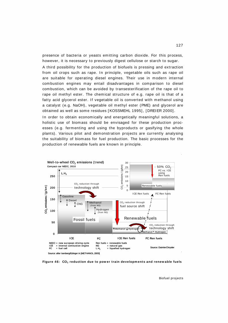
127
Biofuel projects
presence of bacteria or yeasts emitting carbon dioxide. For this process, however, it is necessary to previously digest cellulose or starch to sugar.
A third possibility for the production of biofuels is pressing and extraction from oil crops such as rape. In principle, vegetable oils such as rape oil are suitable for operating diesel engines. Their use in modern internal combustion engines may entail disadvantages in comparison to diesel combustion, which can be avoided by transesterification of the rape oil to rape oil methyl ester. The chemical structure of e.g. rape oil is that of a fatty acid glycerol ester. If vegetable oil is converted with methanol using a catalyst (e.g. NaOH), vegetable oil methyl ester (PME) and glycerol are obtained as well as some residues [KOSSMEHL 1995], [DREIER 2000].
In order to obtain economically and energetically meaningful solutions, a holistic use of biomass should be envisaged for these production proc-esses (e.g. fermenting and using the byproducts or gasifying the whole plants). Various pilot and demonstration projects are currently analysing the suitability of biomass for fuel production. The basic processes for the production of renewable fuels are known in principle.
Figure 46: CO2 reduction due to power train developments and renewable fuels
0
50
100
150
200
250
ICE FC ICE Ren fuels FC Ren fuels
CO
2em
issi
ons
/ (g/k
m)
CNG
GasolineDiesel
Methanol (from NG)
Hydrogen(from NG)
Fossil fuels Renewable fuels
CO2 reduction through
fuel source shift
Well-to-wheel CO2 emissions (trend)Compact-car NEDC, 2010
L.H2
CO2 reduction through
technology shift
CO2 reduction through
technology shiftMethanol HydrogenMethanol
0
5
10
15
20
25
30
ICE Ren fuels FC Ren fuels
CO
2em
issi
ons
/ (g/
km)
FC vs. ICEusingRen fuels
Renewable fuels
- 50% CO2
Hydrogen
NEDC = new european driving cycleICE = internal combustion engineFC = fuel cell
Ren fuels = renewable fuelsNG = natural gasL.H2 = liquefied hydrogen
Source: after Isenberg/Edinger in [METHANOL 2003]
Source: DaimlerChrysler
0
50
100
150
200
250
ICE FC ICE Ren fuels FC Ren fuels
CO
2em
issi
ons
/ (g/k
m)
CNG
GasolineDiesel
Methanol (from NG)
Hydrogen(from NG)
Fossil fuels Renewable fuels
CO2 reduction through
fuel source shift
Well-to-wheel CO2 emissions (trend)Compact-car NEDC, 2010
L.H2
CO2 reduction through
technology shift
CO2 reduction through
technology shiftMethanol HydrogenMethanol
0
5
10
15
20
25
30
ICE Ren fuels FC Ren fuels
CO
2em
issi
ons
/ (g/
km)
FC vs. ICEusingRen fuels
Renewable fuels
- 50% CO2
Hydrogen
NEDC = new european driving cycleICE = internal combustion engineFC = fuel cell
Ren fuels = renewable fuelsNG = natural gasL.H2 = liquefied hydrogen
Source: after Isenberg/Edinger in [METHANOL 2003]
Source: DaimlerChrysler
128
Biofuel projects
Current projects are aimed at obtaining data on energy balances, emis-sions and costs and evaluating optimum concepts for fuel production. These studies are necessary to match decentralized biomass procurement and corresponding processing with decentralized or centralized fuel pro-duction and obtain economically efficient solutions.
Fuels from biomass provide the possibility of making a valuable contribu-tion to CO2 reduction already in the medium term. More detailed investi-gations on this topic can also be found in the status reports of the Trans-port Energy Strategy [EUCAR TES 2002], in the well-to-wheels analysis of General Motors [GM 2002], in Isenberg/Edinger [ISENBERG EDINGER 2002] and in L-B-Systemtechnik [SCHINDLER WEINDORF 2002] as well as, in particular, in the well-to-wheel study [CONCAWE 2005].
Figure 46 illustrates possible advantages with respect to CO2 reduction due to power train developments and changes in the fuels used. CO2 re-ductions of some 10% can be achieved with advanced internal combustion engines as well as fuel cell power trains and the use of fossil fuels. Signifi-cant advantages are obtained by the use of renewable energies for fuel production. In this case, fuel cell systems can fully display their efficiency advantage.
10.3 Motivation for the use of biomass as an energy carrier
Reasons for the remarkable role of biomass in "late and post-fossil" en-ergy scenarios are, among others:
– large globally available potential of biomass (no geographical concentra-tion) along with storability and transportability and thus significant po-tential contribution to securing energy supply in the long term,
– wide range of applications (generation of heat, electricity and fuels) along with the availability of the relevant energy conversion technolo-gies; economic efficiency in part already existing, e.g. in decentralized combined heat and power systems [ORTMAIER 2001],
– conservation of the resources of fossil energy carriers and thus in part lower dependence on oil imports (example: USA, EU, Brazil) due to the use of domestic energy carriers, new tasks for agriculture (examples: USA and EU, the latter above all in view of its recent eastward enlarge-ment),
– contribution to environmental protection: CO2 neutrality in use and clear CO2 reduction in the full fuel cycle,
129
Biofuel projects
– use of so-called "set-aside areas" (examples: USA, EU, D) and thus possible improvement of the income situation of agriculture (substitu-tion markets due to energy crops); new products for the agriculture of the Third World,
– beginning willingness of energy utilities to invest in renewable energies; Shell expects to produce approx. 50% of the fuels from biomass by about 2060.
10.4 Status of biogenic methanol production
The basic processes for the production of biomethanol are tested and demonstrated in laboratory experiments. Inadequately answered as yet are questions concerning quantitative statements on emission and mate-rial balances and on costs for economical fuel production:
– What energy input with corresponding emissions is necessary for the provision and conditioning as well as the processing of biomass (in-put/output analysis)?
– With what efficiency is the biomass processed to methanol (current val-ues are in the range of 40–55%; TES: 48–56%, GM: 54%, ECOTRAF-FIC: 51%)?
– At what costs will biomethanol be producible?
– How greatly centralized/decentralized must biomass provision and sub-sequent processing take place? Catchment areas with a radius of up to 20–25 km seem to be economically meaningful for the use of biomass.
– Can the two steps of biomass provision and processing be separated? There are solution approaches for joint processing in a decentralized plant (Prof. Th. Willner, Hamburg), for the separation of decentralized biomass processing from centralized fuel production ([WOLF RUDLOFF 2001], [WOLF 2002] and [SCHAUB 2002].
Since biomass arises locally, it is cost-intensive to collect and process it. Technical and economic solutions are needed to process biomass in decen-tralized, small to medium-sized gasification units, compress it energeti-cally (bio crude oil, BCO) and transport the intermediate products to large fuel conditioning plants.
At present, various experimental facilities are being constructed and oper-ated to answer the above questions. Finally, an answer is also to be given to the question of whether or not biogenic fuel production appears mean-ingful.
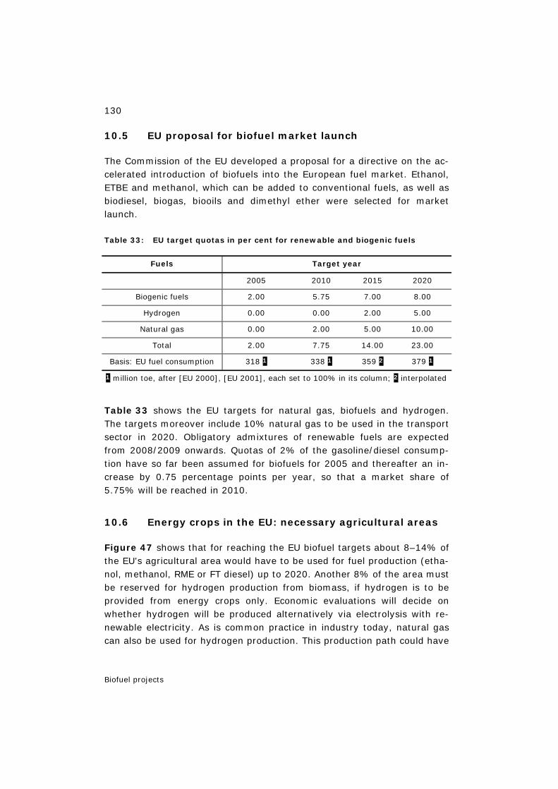
130
Biofuel projects
10.5 EU proposal for biofuel market launch
The Commission of the EU developed a proposal for a directive on the ac-celerated introduction of biofuels into the European fuel market. Ethanol, ETBE and methanol, which can be added to conventional fuels, as well as biodiesel, biogas, biooils and dimethyl ether were selected for market launch.
Table 33: EU target quotas in per cent for renewable and biogenic fuels
Fuels Target year
2005 2010 2015 2020
Biogenic fuels 2.00 5.75 7.00 8.00
Hydrogen 0.00 0.00 2.00 5.00
Natural gas 0.00 2.00 5.00 10.00
Total 2.00 7.75 14.00 23.00
Basis: EU fuel consumption 318 1 338 1 359 2 379 1
1 million toe, after [EU 2000], [EU 2001], each set to 100% in its column; 2 interpolated
Table 33 shows the EU targets for natural gas, biofuels and hydrogen. The targets moreover include 10% natural gas to be used in the transport sector in 2020. Obligatory admixtures of renewable fuels are expected from 2008/2009 onwards. Quotas of 2% of the gasoline/diesel consump-tion have so far been assumed for biofuels for 2005 and thereafter an in-crease by 0.75 percentage points per year, so that a market share of 5.75% will be reached in 2010.
10.6 Energy crops in the EU: necessary agricultural areas
Figure 47 shows that for reaching the EU biofuel targets about 8–14% of the EU's agricultural area would have to be used for fuel production (etha-nol, methanol, RME or FT diesel) up to 2020. Another 8% of the area must be reserved for hydrogen production from biomass, if hydrogen is to be provided from energy crops only. Economic evaluations will decide on whether hydrogen will be produced alternatively via electrolysis with re-newable electricity. As is common practice in industry today, natural gas can also be used for hydrogen production. This production path could have
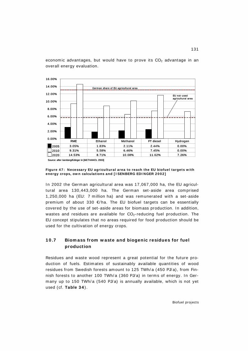
131
Biofuel projects
economic advantages, but would have to prove its CO2 advantage in an overall energy evaluation.
Figure 47: Necessary EU agricultural area to reach the EU biofuel targets with energy crops, own calculations and [ISENBERG EDINGER 2002]
In 2002 the German agricultural area was 17,067,000 ha, the EU agricul-tural area 130,443,000 ha. The German set-aside area comprised 1,250,000 ha (EU: 7 million ha) and was remunerated with a set-aside premium of about 330 €/ha. The EU biofuel targets can be essentially covered by the use of set-aside areas for biomass production. In addition, wastes and residues are available for CO2-reducing fuel production. The EU concept stipulates that no areas required for food production should be used for the cultivation of energy crops.
10.7 Biomass from waste and biogenic residues for fuel production
Residues and waste wood represent a great potential for the future pro-duction of fuels. Estimates of sustainably available quantities of wood residues from Swedish forests amount to 125 TWh/a (450 PJ/a), from Fin-nish forests to another 100 TWh/a (360 PJ/a) in terms of energy. In Ger-many up to 150 TWh/a (540 PJ/a) is annually available, which is not yet used (cf. Table 34).
0.00%
2.00%
4.00%
6.00%
8.00%
10.00%
12.00%
14.00%
16.00%
2005 3.05% 1.83% 2.11% 2.44% 0.00%
2010 9.31% 5.58% 6.46% 7.45% 0.00%
2020 14.53% 8.71% 10.08% 11.62% 7.26%
RME Ethanol Methanol FT diesel Hydrogen
EU not-usedagricultural area
German share of EU agricultural area
Source: after Isenberg/Edinger in [METHANOL 2003]
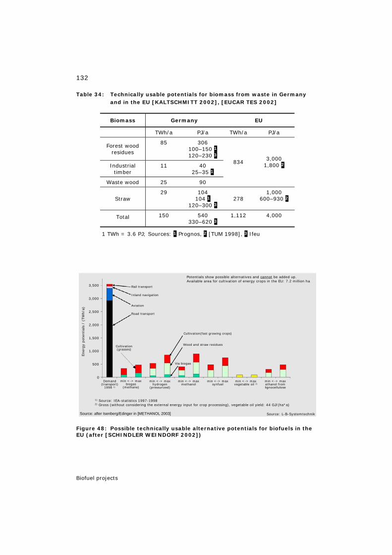
132
Biofuel projects
Table 34: Technically usable potentials for biomass from waste in Germany and in the EU [KALTSCHMITT 2002], [EUCAR TES 2002]
Biomass Germany EU
TWh/a PJ/a TWh/a PJ/a
Forest wood residues
85 306 100–150 1 120–230 3
Industrial timber
11 40 25–35 1
Waste wood 25 90
834
3,000 1,800 2
Straw
29 104 104 1
120–300 3
278
1,000 600–930 2
Total 150 540 330–620 3
1,112 4,000
1 TWh = 3.6 PJ; Sources: 1 Prognos, 2 [TUM 1998], 3 Ifeu
Figure 48: Possible technically usable alternative potentials for biofuels in the EU (after [SCHINDLER WEINDORF 2002])
min <-> maxhydrogen
(pressurized)
min <-> maxbiogas
(methane)
min <-> maxmethanol
min <-> maxsynfuel
min <-> maxvegetable oil 2)
min <-> maxethanol fromlignocellulose
Demand(transport)
1998 1)
3,500
3,000
2,500
2,000
1,500
1,000
500
0
Cultivation(grasses)
Cultivation(fast growing crops)
Wood and straw residues
Via biogas
Road transport
Aviation
Inland navigation
Rail transport
Ener
gy
pote
ntial
s/
(TW
h/a
)
Potentials show possible alternatives and cannot be added up.Available area for cultivation of energy crops in the EU: 7.2 million ha
1) Source: IEA-statistics 1997-19982) Gross (without considering the external energy input for crop processing), vegetable oil yield: 44 GJ/(ha*a)
Source: L-B-SystemtechnikSource: after Isenberg/Edinger in [METHANOL 2003]
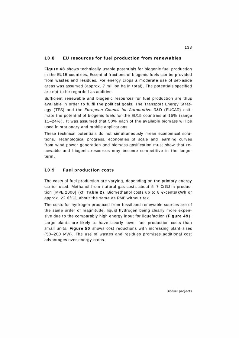
133
Biofuel projects
10.8 EU resources for fuel production from renewables
Figure 48 shows technically usable potentials for biogenic fuel production in the EU15 countries. Essential fractions of biogenic fuels can be provided from wastes and residues. For energy crops a moderate use of set-aside areas was assumed (approx. 7 million ha in total). The potentials specified are not to be regarded as additive.
Sufficient renewable and biogenic resources for fuel production are thus available in order to fulfil the political goals. The Transport Energy Strat-egy (TES) and the European Council for Automotive R&D (EUCAR) esti-mate the potential of biogenic fuels for the EU15 countries at 15% (range 11–24%). It was assumed that 50% each of the available biomass will be used in stationary and mobile applications.
These technical potentials do not simultaneously mean economical solu-tions. Technological progress, economies of scale and learning curves from wind power generation and biomass gasification must show that re-newable and biogenic resources may become competitive in the longer term.
10.9 Fuel production costs
The costs of fuel production are varying, depending on the primary energy carrier used. Methanol from natural gas costs about 5–7 €/GJ in produc-tion [MPE 2000] (cf. Table 2). Biomethanol costs up to 8 €-cents/kWh or approx. 22 €/GJ, about the same as RME without tax.
The costs for hydrogen produced from fossil and renewable sources are of the same order of magnitude, liquid hydrogen being clearly more expen-sive due to the comparably high energy input for liquefaction (Figure 49).
Large plants are likely to have clearly lower fuel production costs than small units. Figure 50 shows cost reductions with increasing plant sizes (50–200 MW). The use of wastes and residues promises additional cost advantages over energy crops.
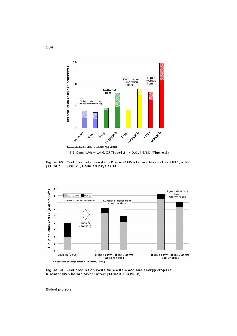
134
Biofuel projects
5 €-Cent/kWh ≈ 14 €/GJ (Tabel 2) ≈ 0,014 €/MJ (Figure 2)
Figure 49: Fuel production costs in €-cents/kWh before taxes after 2010; after [EUCAR TES 2002], DaimlerChrysler AG
Figure 50: Fuel production costs for waste wood and energy crops in €-cents/kWh before taxes; after: [EUCAR TES 2002]
0
5
10
15
gaso
line
dies
elfoss
il
rene
wable
foss
il
rene
wable
foss
il
rene
wable
Liquidhydrogenfrom …
Compressedhydrogenfrom …
Methanolfrom …
Reference case(basis: conventional oil)
Fuel
pro
duct
ion
cost
s/
(€-c
ents
/kW
h)
Source: after Isenberg/Edinger in [METHANOL 2003]
0
5
10
15
gaso
line
dies
elfoss
il
rene
wable
foss
il
rene
wable
foss
il
rene
wable
Liquidhydrogenfrom …
Compressedhydrogenfrom …
Methanolfrom …
Reference case(basis: conventional oil)
Fuel
pro
duct
ion
cost
s/
(€-c
ents
/kW
h)
Source: after Isenberg/Edinger in [METHANOL 2003]
0
1
2
3
4
5
6
7
8
9
gasoline/diesel plant 50 MW plant 200 MWwood residues
Cents/kWh Range
Synthetic diesel fromwood residues
Biodiesel(FAME *)
Synthetic dieselfrom
energy crops
Fuel
pro
duct
ion
cost
s/
(€-c
ents
/kW
h)
plant 50 MW plant 200 MWenergy crops
* FAME = fatty acid methyl ester
Source: after Isenberg/Edinger in [METHANOL 2003]
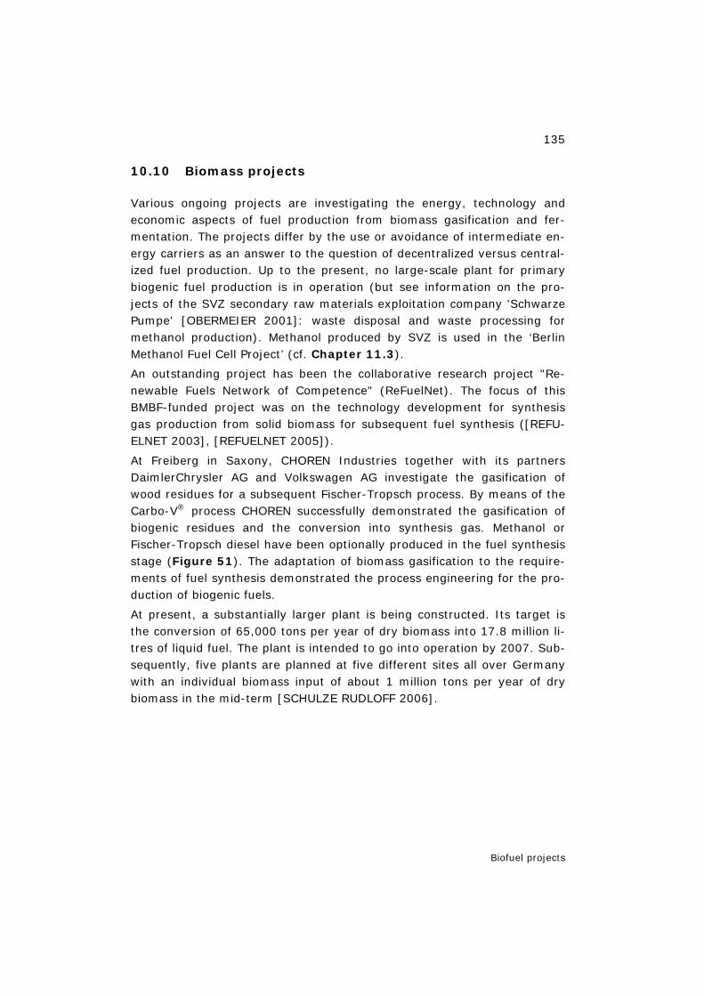
135
Biofuel projects
10.10 Biomass projects
Various ongoing projects are investigating the energy, technology and economic aspects of fuel production from biomass gasification and fer-mentation. The projects differ by the use or avoidance of intermediate en-ergy carriers as an answer to the question of decentralized versus central-ized fuel production. Up to the present, no large-scale plant for primary biogenic fuel production is in operation (but see information on the pro-jects of the SVZ secondary raw materials exploitation company 'Schwarze Pumpe' [OBERMEIER 2001]: waste disposal and waste processing for methanol production). Methanol produced by SVZ is used in the ‘Berlin Methanol Fuel Cell Project’ (cf. Chapter 11.3).
An outstanding project has been the collaborative research project "Re-newable Fuels Network of Competence" (ReFuelNet). The focus of this BMBF-funded project was on the technology development for synthesis gas production from solid biomass for subsequent fuel synthesis ([REFU-ELNET 2003], [REFUELNET 2005]).
At Freiberg in Saxony, CHOREN Industries together with its partners DaimlerChrysler AG and Volkswagen AG investigate the gasification of wood residues for a subsequent Fischer-Tropsch process. By means of the Carbo-V® process CHOREN successfully demonstrated the gasification of biogenic residues and the conversion into synthesis gas. Methanol or Fischer-Tropsch diesel have been optionally produced in the fuel synthesis stage (Figure 51). The adaptation of biomass gasification to the require-ments of fuel synthesis demonstrated the process engineering for the pro-duction of biogenic fuels.
At present, a substantially larger plant is being constructed. Its target is the conversion of 65,000 tons per year of dry biomass into 17.8 million li-tres of liquid fuel. The plant is intended to go into operation by 2007. Sub-sequently, five plants are planned at five different sites all over Germany with an individual biomass input of about 1 million tons per year of dry biomass in the mid-term [SCHULZE RUDLOFF 2006].
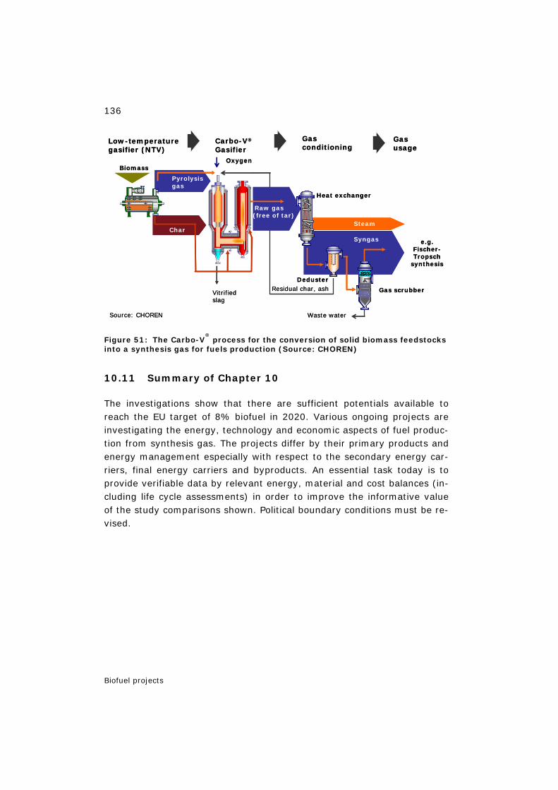
136
Biofuel projects
Figure 51: The Carbo-V® process for the conversion of solid biomass feedstocks
into a synthesis gas for fuels production (Source: CHOREN)
10.11 Summary of Chapter 10
The investigations show that there are sufficient potentials available to reach the EU target of 8% biofuel in 2020. Various ongoing projects are investigating the energy, technology and economic aspects of fuel produc-tion from synthesis gas. The projects differ by their primary products and energy management especially with respect to the secondary energy car-riers, final energy carriers and byproducts. An essential task today is to provide verifiable data by relevant energy, material and cost balances (in-cluding life cycle assessments) in order to improve the informative value of the study comparisons shown. Political boundary conditions must be re-vised.
Residual char, ash
Syngas
Steam
Gas scrubber
Waste water
Vitrifiedslag
Carbo-V®
Gasifier
Raw gas (free of tar)
Oxygen
Heat exchanger
Deduster
Gasconditioning
Gasusage
Char
Pyrolysisgas
Biomass
Low-temperaturegasifier (NTV)
e.g. Fischer-Tropsch
synthesis
Source: CHOREN
Residual char, ash
Syngas
Steam
Gas scrubber
Waste water
Vitrifiedslag
Carbo-V®
Gasifier
Raw gas (free of tar)
Oxygen
Heat exchanger
Deduster
Gasconditioning
Gasusage
Char
Pyrolysisgas
Biomass
Low-temperaturegasifier (NTV)
e.g. Fischer-Tropsch
synthesis
Source: CHOREN
137
Special aspects
11 Special aspects
11.1 Fuel cells for portable applications
Portable applications with grid-independent energy supply include above all emergency power-generating units (premium power, uninterruptible power systems, UPS) for medical facilities and rescue services, alarm and warning systems and telecommunications; added to this are mobile phones and portable computers, camcorders, devices for container and waggon tracing, site determination devices, leisure and camping equip-ment [STOLTEN et al. 2002]. Self-contained power supplies also included auxiliary power units (APUs), which can be operated independently of the drive unit of a vehicle.
The relatively short half-life of mobile electronic appliances with respect to the latest state of the art and their short service life opens up the possibil-ity of equipping new generations of devices faster with novel electric power generators [PEHNT 2002]. The most important criteria are energy density, operating life, charging/replacement time and storage volume [SFC 2003].
These criteria are fulfilled, for example, by small fuel cells. They fit in small devices confined in space, have an acceptable weight and increase the grid-independent operating time. Only the storage unit of the energy carrier must be replaced. Candidates for small devices are low-temperature fuel cells such as PEFCs and DMFCs, whereas APUs may re-quire high-temperature fuel cells such as the SOFC.
PEFCs can be operated with pure hydrogen from liquid-, pressure-, hy-dride- or carbon-based storage units or with hydrogen from the reforming of liquid energy carriers. For portable small devices, reforming appeared not mature enough just a few years ago. In contrast, direct electricity generation from alcohols in fuel cells suggested itself, e.g. methanol in di-rect methanol fuel cells [OERTEL FLEISCHER 2001]. However, develop-ment is still needed and possible for the DMFC concerning its performance characteristics, efficiency, production costs and service life. The perform-ance target is to compete with lithium/ion batteries. The computer manu-facturer CASIO holds the view today that DMFCs cannot be applied – for example, in laptops – before they have demonstrated sufficient power density. Until then, a modified low-temperature fuel cell type will be pre-ferred whose hydrogen demand is to be covered from the reforming of
138
Special aspects
methanol ([FCTD 2003], [FCWRK 2003]). Besides PEFCs and DMFCs, other fuel cells and other energy carriers (e.g. diesel or kerosene [SFC 2003]) with and without reformer are also conceivable. The aim of devel-opments is micro fuel cells and micro-reformers.
11.2 Ban on MTBE
Since 1979, MTBE has been used nationwide at low admixture levels in gasoline to replace lead as an octane booster or anti-knocking agent. Public Law 101–549 (Clean Air Act Amendments of 1990) established a fuel oxygenate standard according to which reformulated gasoline must contain at least 2wt% oxygen and the fuel industry responded to the fuel oxygenate standard by making substantial investments in MTBE production capacity and systems to deliver MTBE-containing gasoline to the market (sec. 1502) [ENERGY ACT 2005].
Because of the hazard potential of MTBE nationwide either a partial or a complete ban was placed on MTBE. In the State of California (EPA region 9 19), the admixture of MTBE to reformulated gasoline has been prohibited since 1/1/2004 [CAGOV 2002]. In the meantime, less than half of the states have phased out MTBE except the states of Maine and New Hampshire (EPA region 1): the phase-out date of their partial ban was fixed on 1/1/2007 [EPA 2004].
The phase-out of MTBE has led to a large decrease of MTBE imports from East Asia and the Middle East. Exports to the U.S. have declined by about 47% (850,000 tons) since 2001. But this volume seems to be needed in view of the growing demand in Asia because of lead phase-out and growth in gasoline consumption [SHIR 2005].
Ethanol is considered to be the leading oxygen donor for the replacement of methanol 20. Due to the lower molar mass of ethanol in comparison to MTBE, however, the replacement of MTBE by ethanol – providing the minimum oxygen content – leads to a reduction in volume and reduces
19 In the context of fuel supply (e.g. reformulated gasoline, MTBE) special US regions or states are often referred to as PADDs. In case of environmental problems another classi-fication is used, the EPA region (cf. Chapter 14.2.2).
20 Concerning the volatility of MTBE and ethanol from water cf. Henry coefficient (Table 26).

139
Special aspects
the octane number of the reformulated gasoline. In addition, air pollutant emissions (VOC, MSAT, NOx) are increasing. As a consequence of a ban on MTBE, the mentioned losses and emission disadvantages have to be compensated by modifying the design of the reformulated gasoline via production changes in the refinery processes and by additional measures.
Both the ban on MTBE and the introduction of ethanol (from corn) as a possible substitute or a fuel have been discussed nationwide by the different interest groups in the USA [EIA 2002], [MI 2003], [PATZEK 2003], [BLUEBOOK 2003].
On 8/8/2005 the U.S. Energy Bill (Energy Policy Act of 2005 / HR6) was adopted and signed into law by President Bush. This did not ban MTBE at the federal level. In order not to filibuster the bill, as was done in 2003, among other items the MTBE liability waiver was not included (shielding the companies responsible for MTBE contamination from their full financial liability for the damage they have caused). These issues will be pursued in separate initiatives [EWALL 2005]. A provision to move MTBE lawsuits from state courts to federal courts remained in the bill (sec. 1503) and the elimination of the oxygen content requirement for reformulated gasoline was included (sec. 1504) [ENERGY ACT 2005].
11.3 Berlin methanol fuel cell project 21
On 30 September 2004, Bewag AG – together with the partners Vattenfall Europe, E.ON Energie and the manufacturer MTU CFC Solutions – put the first methanol-operated high-temperature fuel cell worldwide into opera-tion in its heating plant in Berlin-Treptow. Methanol can be produced from various biomass products and residues and is considered to be one of the options of the future for the energy market. A prerequisite for efficient utilization as an energy carrier is the use in energy conversion systems with high efficiency, such as fuel cells. The technology of the MCFC (mol-ten carbonate fuel cell) is regarded as pioneering. The project is therefore financially supported by the Federal Ministry of Economics and Labour.
The project aims at testing this new technology under practical conditions. For this purpose, the fuel cell system will be operated for several years in conjunction with the existing electricity and heat supply units. The metha-nol needed for operation comes from the secondary raw materials exploi-
21 Chapter 11.3 sources: figures after Pokojski/Radke (BEWAG/Vattenfall), 2005.
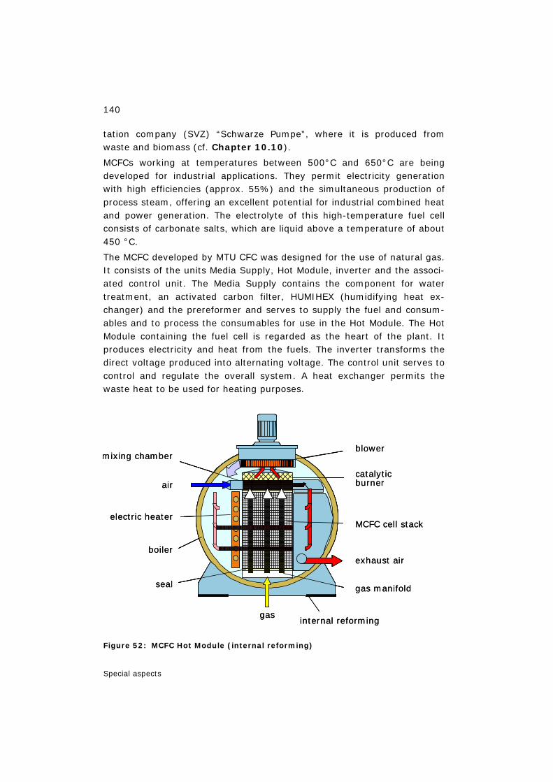
140
Special aspects
tation company (SVZ) “Schwarze Pumpe”, where it is produced from waste and biomass (cf. Chapter 10.10).
MCFCs working at temperatures between 500°C and 650°C are being developed for industrial applications. They permit electricity generation with high efficiencies (approx. 55%) and the simultaneous production of process steam, offering an excellent potential for industrial combined heat and power generation. The electrolyte of this high-temperature fuel cell consists of carbonate salts, which are liquid above a temperature of about 450 °C.
The MCFC developed by MTU CFC was designed for the use of natural gas. It consists of the units Media Supply, Hot Module, inverter and the associ-ated control unit. The Media Supply contains the component for water treatment, an activated carbon filter, HUMIHEX (humidifying heat ex-changer) and the prereformer and serves to supply the fuel and consum-ables and to process the consumables for use in the Hot Module. The Hot Module containing the fuel cell is regarded as the heart of the plant. It produces electricity and heat from the fuels. The inverter transforms the direct voltage produced into alternating voltage. The control unit serves to control and regulate the overall system. A heat exchanger permits the waste heat to be used for heating purposes.
Figure 52: MCFC Hot Module (internal reforming)
exhaust air
gas manifold
MCFC cell stack
blower
catalyticburner
gas
mixing chamber
air
electric heater
boiler
seal
internal reforming
exhaust air
gas manifold
MCFC cell stack
blower
catalyticburner
gas
mixing chamber
air
electric heater
boiler
seal
internal reforming
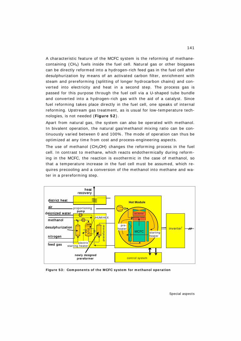
141
Special aspects
A characteristic feature of the MCFC system is the reforming of methane-containing (CH4) fuels inside the fuel cell. Natural gas or other biogases can be directly reformed into a hydrogen-rich feed gas in the fuel cell after desulphurization by means of an activated carbon filter, enrichment with steam and prereforming (splitting of longer hydrocarbon chains) and con-verted into electricity and heat in a second step. The process gas is passed for this purpose through the fuel cell via a U-shaped tube bundle and converted into a hydrogen-rich gas with the aid of a catalyst. Since fuel reforming takes place directly in the fuel cell, one speaks of internal reforming. Upstream gas treatment, as is usual for low-temperature tech-nologies, is not needed (Figure 52).
Apart from natural gas, the system can also be operated with methanol. In bivalent operation, the natural gas/methanol mixing ratio can be con-tinuously varied between 0 and 100%. The mode of operation can thus be optimized at any time from cost and process-engineering aspects.
The use of methanol (CH3OH) changes the reforming process in the fuel cell. In contrast to methane, which reacts endothermically during reform-ing in the MCFC, the reaction is exothermic in the case of methanol, so that a temperature increase in the fuel cell must be assumed, which re-quires precooling and a conversion of the methanol into methane and wa-ter in a prereforming step.
Figure 53: Components of the MCFC system for methanol operation
FC
district heat
heatrecovery
-
deionized water
elektrischer Start Heizer
HUMIHEX
desulphurization
Pre-
Refo
rmer
air
nitrogen
feed gas
pump
Control System
Wechsel-richter
FC
Kat.BrennerMischzone
Hot Module
Vor-heizer
StartHeizer
MCFC
methanol
newly designedprereformer
FCFC
-
electricstarting heater
HUMIHEX
pre
refo
rmer
control system
inverter-
FCFC
cat.burner
mixing zone
Hot Module
startingheater
MCFC
pre-heater
proportioning
FC
district heat
heatrecovery
-
deionized water
elektrischer Start Heizer
HUMIHEX
desulphurization
Pre-
Refo
rmer
air
nitrogen
feed gas
pump
Control System
Wechsel-richter
FC
Kat.BrennerMischzone
Hot Module
Vor-heizer
StartHeizer
MCFC
methanol
newly designedprereformer
FCFC
-
electricstarting heater
HUMIHEX
pre
refo
rmer
control system
inverter-
FCFC
cat.burner
mixing zone
Hot Module
startingheater
MCFC
pre-heater
proportioning
142
Special aspects
For this reason, a new air-cooled prereformer has been developed. As a tubular heat exchanger it ensures sufficient cooling of the feed gas at any time and makes it possible to largely convert the methanol into methane and water.
In addition to the existing Media Supply, a methanol rack has been pro-vided, which contains all the components additionally required – new pre-reformer, fresh air fan and exhaust air system. Methanol is supplied by the HUMIHEX (Figure 53).
The system has an electrical power output of 220 kW and a thermal power output of approx. 170 kW. The electrical net efficiency is in the range of 45% at full load, the overall efficiency including heat recovery is roughly 80%.
The costs of the project planned for three years amount to roughly 4.5 million €. About 2 million € is borne by the Federal Ministry of Economics and Labour. The remaining costs are shared between the project partners Vattenfall Europe and E.ON.
11.4 Summary of Chapter 11
The most important criteria for portable applications of fuel cells are en-ergy density, operating life, charging/replacement time and storage vol-ume. Candidates in the low-temperature range are PEFC and DMFC. Pure hydrogen or hydrogen from the reforming of liquid energy carriers can be used as the fuel. Further development for the fuel cells is still needed. The performance target is to compete with lithium/ion batteries. The aim of developments are micro fuel cells and micro-reformers.
Less than half of the states have phased out MTBE. The U.S. Energy Bill of 8/8/2005 did not ban MTBE at the federal level. This issue will be pursued. A provision to move MTBE lawsuits from state courts to federal courts re-mained in the bill and the elimination of the oxygen content requirement for reformulated gasoline was included.
Aim of the Berlin project is testing the methanol-operated high-temperature fuel cell under practical conditions. The MCFC which was de-signed for the use of natural gas has been modified with a new air-cooled prereformer in a methanol rack. Thereby the system can be operated with natural gas and/or methanol in a bivalent manner.
143
Summary
12 Summary
In the medium- to long-term perspective, new final energy carriers for vehicles will be produced on a fossil and increasingly on a renewable basis and will play a part in the energy market. In order to utilize them, in addi-tion to further developed internal combustion engines, hybrid vehicles and electrically driven fuel cell vehicles will also have to be taken into consid-eration in future.
Methanol as an energy carrier can make an essential contribution here. Methanol can be used in an environmentally friendly manner in gaso-line/methanol mixtures for flexible fuel vehicles with internal combustion engines and in diesel engines with pure methanol. Furthermore, it can be used in fuel cell vehicles with on-board hydrogen production, directly in di-rect methanol fuel cell drives and in stationary systems for electricity and heat generation. Finally, in portable applications it serves as an energy carrier for electric power generators.
Methanol can be produced both from fossil energy sources – today mainly from natural gas for the chemicals market – and from biomass or waste materials through the process steps of synthesis gas generation with sub-sequent methanol synthesis. In this connection, the low-cost remote or stranded natural gas plays a particular role, which can be converted into methanol as an energy carrier or chemical feedstock far away from the markets and from a pipeline infrastructure and then transported to the consumers. For the fuel supply in the European Union (EU) 3% methanol can already be used today as an additive to gasoline. Since 2005 an EU directive for fuels on a renewable basis has required a share of at first 2% in total fuel supplies.
At the filling station, the costs of providing methanol as an energy carrier based on low-cost natural gas could only be insignificantly higher than for gasoline/diesel before tax under the present boundary conditions. More-over, methanol is a liquid energy carrier like gasoline/diesel fuel which we are used to handle today and has a storage density of about 50% of that for gasoline/diesel refuelling systems; but it is clearly higher than that of hydrogen refuelling systems. If used in accordance with regulations and if all relevant rules are observed, handling methanol does not represent any health or safety problem.
Methanol can also be used to produce other fuels such as hydrogen, di-methyl ether or synthetic gasoline or diesel. The latter can also be co-

144
Summary
produced with propylene for the plastics market, in particular on the basis of low-cost large natural gas deposits and associated gas far away from all pipeline systems.
In this book, the processes for the production and use of methanol are presented and evaluated, markets and future options discussed and issues of safety and environmental impacts addressed with the following mes-sages.
Methanol as an option for the energy market should be maintained be-cause it is currently impossible to decide on future new energy carriers for road traffic; all relevant development approaches should be further pur-sued.
Feasible concepts for vehicles with methanol, reformer, fuel cell and electric drive still have to undergo a further development phase with re-spect to cost reduction and technical performance. In the long run, the use of methanol in direct methanol fuel cells (DMFCs) for vehicle drives could play a key role; DMFCs are being developed and tested today for portable and light traction applications.
Methanol production is chiefly based on natural gas today, in Germany also on residual oils. The production of methanol on the basis of input ma-terials other than natural gas (e.g. coal or residual oils) is more complex in terms of process engineering.
Methanol use today takes mainly place in the chemical industry. In the EU methanol can be used as a gasoline additive; it is also used for MTBE production in the EU.
Methanol prices today will be greatly influenced by the price of natural gas. The ban on the use of MTBE especially in California and in many other US states, the growing demand of MTBE in Asia on the one hand, and the enhanced use of inexpensive associated gas for the production of methanol in so-called megaplants, on the other, will have severe implica-tions for the future methanol market.
Future methanol markets for road traffic cannot be defined at present. If additional production capacities should be required in the future, their selection should be made from the aspect of a methanol provision that is ecologically justifiable and competitive on the energy market. Further-more, a fiscal policy not in sight today would have to support the bound-ary conditions for the introduction of new energy carriers in road traffic.
Investments in increasingly larger methanol plants are being made but it could be possible that new capacity not all expected will become com-

145
Summary
mercial and available for the market. All the new production facilities pro-duce methanol where the gas deposit is located and they have favourable gas conditions in the long term. But none of these facilities will suffice to produce and supply the quantities required if syngas/methanol were to play an increasing role as a new energy source for road traffic one day.
146
Literature
13 Literature
13.1 Literature used
[AASBERG-PETERSEN et al. 2004] Aasberg-Petersen, K. et al.: Synthesis Gas Production for FT Syn-thesis, Stud. Surf. Sci. Cat. 152 (2004), p. 258–405
[ADACHI 2003] S. Adachi, S.: Fuel Cell System for Motorcycles, in: Yamaha Motor Technical Review, 2004-3, No. 37
[ADL 2000] Cost Analysis of Fuel Cell System for Transportation, Ref. 49739, Ar-thur de Little Inc., Cambridge/MA, 2000
[ADL 2002] Guidance for Transportation Technologies: Fuel Choice for Fuel Cell Vehicles, Final Report to DOE, Case 35340–00, Arthur D. Little Inc., Cambridge/MA, 2002
[Al SAYED 2000] Al Sayed, M.: Developing Methanol and Petrochemical Industries in the Middle East, 18th World Methanol Conference, Kopenhagen/DK, November 8–10, 2000
[ALLAM et al. 1998] Allam, R.J., Brown, D.M., Stein, V.E., Heydorn, E.C., Klosek J.: Op-eration of the First Liquid Phase Methanol (LPMEOHTM) Facility and the Potential Benefits for IGCC Technology, I. Chem E Conference 1998, Dresden/Germany (1998)
[ARAL 2001] Nierhauve, B. (Aral): Alternative Kraftstoffe für zukünftige Antriebe, in: Proceedings AVL Int. Congress, Graz/A, September 6–7, 2001
[ASKGAARD et al. 1995] Askgaard, T.S., Nørskov, J.K., Ovesen, C.V., Stoltze, P.: A Kinetic Model of Methanol Synthesis, J. Catal., 156 (1995), p. 229–242
[BAKKERUD et al. 2004] Bakkerud, P.K., Gøl, N.J., Nergaard, J., Aasberg-Petersen, K., Dybkjær, I.: Preferred synthesis gas production routes for GTL, Stud. Surf. Sci. Cat. 147 (2004), p. 13–18.
147
Literature
[BALTHASAR HILSEBEIN 2003] Balthasar, W., Hilsebein, W.: Methanol as a Feedstock for Power, Fuel and Olefins, Nitrogen & Methanol, 261, January/February, 2003
[BLUEBOOK 2003] http://www.arb.ca.gov/bluebook/bluebook.htm (2003)
[BRASIL 2000] http://www.brasil.terravista.pt (2000)
[CAFCP 2003] http://www.fuelcellpartnership.org (2003)
[CAGOV 2002] Executive Order D-52-02, Executive Department, State of California, March 14, 2002
[CEA 2003] Lucchese, P. CEA/F: personal communication, 2003
[CEC 2001] State of California Energy Commission: California Clean Fuels Market Assessment 2001, Consultant Report, Sacramento/CA; http://www.energy.ca.gov (2001)
[CELANESE 2003] http://www.celanese.com (September 2003)
[CHEMSYSTEMS 2003] Nexant Petroleum & Chemicals; http://www.nexant.com
[CHRIST 1994] Christensen, T.S., Primdahl, I.I.: Hydrocarb. Proc. 73 (3) (1994), p. 39.
[CHRIST 1998] Christensen, T.S., Seier Christensen, P., Bak Hansen, J.-H., Prim-dahl, I.I.: Stud.Surf.Sci.Catal. 199 (1998), p. 883.
[CHRISTENSEN PRIMDAHL 1994] Christensen, T., Primdahl, I.: Improve Syngas Production Using Autothermal Reforming, Hydrocarbon Processing, March 1994
[CLAUSEN et al. 1991] Clausen, B.S., Steffensen, G., Fabius, B., Villadsen, J., Feidenhans’l, R. and Topsøe, H.: J. Catal. 132 (1991), p. 524
[CMAI 2001] CMAI completes 2001 World Methanol Analysis, Press Release; http:// www.cmaiglobal.com (October 16, 2001)
148
Literature
[CONCAWE 2005] Well-to-wheels analysis of future automotive fuels and powertrains in the European context, Well-to-Wheels Report, Version 2a, De-cember 2005; http://ies.jrc.cec.eu.int/WTW
[DE WITT 2006] DeWitt Asia Pacific Global Methanol & MTBE Conference, Proceedings (to be published), Kuala Lumpur/Malaysia, March 8–9, 2006
[DIESELNET 2003] http://www.dieselnet.com
[DILLON et al. 2003] Dillon, R., Scrinivasan, S., Arico, A.S., Antonucci, V. : International Activities in DMFC R&D: Status of Technologies and Potential Appli-cations, in: Journal of Power Sources, Vol. 127, 1999, pp. 112–126
[DOE 2002] Proceedings of the Workshop Fuel Cells for Portable Power, U.S. De-partment of Energy, Office of Hydrogen, Fuel Cells and Infrastruc-ture Technologies, Phoenix, Arizona, January 15–17, 2002
[DOE 2003] Annual Energy Outlook 2003 with Projections to 2025, Energy In-formation Administration, Report #: DOE/EIA-0383(2003), Released January 9, 2003
[DOHLE 2003] Dohle, H., Janssen, H., Mergel, J., Nölke, M.: Design Criteria for PEM and DMFC Fuel Cell Systems, in: Proceedings 2nd European PEFC Fo-rum, Lucerne/Switzerland, June 30–July 4, 2003
[DREIER 2000] Dreier, Th.: Ganzheitliche Systemanalyse und globale Potenzialana-lyse biogener Kraftstoffe, PhD thesis, TU Munich, Ife Monografic Se-ries No. 42, E&M Verlag, Herrsching, 2000
[DYBKJÆR et al. 1997] Dybkjær, I., Hansen, J.B.: Large-Scale Production of Alternative Synthetic Fuels from Natural Gas, Stud. Surf. Sci. Cat. 107 (1997), p. 99–116
[DYBKJÆR et al. 2004] Dybkjær, I., Madsen, S.W.: Compact Hydrogen Plants, Hydcar. Eng. 9,11 (2004), p. 23–25
[ECO 2001] Ahlvik P., Brandberg Å.: Well-To-Wheel Efficiency for alternative fu-
149
Literature
els from natural gas or biomass, Swedish National Road Administra-tion, Publication number 85, 2001; http://www.vv.se/publ_blank/bokhylla/miljo/ lista.htm
[EDINGER/ISENBERG/HÖHLEIN 2003] Edinger, E., Isenberg, G., Höhlein, B.: Methanol from fossil and re-newable resources, in: Vielstich, W., Lamm, A., Gasteiger, H. (Eds.): Handbook of Fuel Cells – Fundamentals, Technology and Applica-tions, John Wiley & Sons, Ltd., Chichester/GB, 2003
[EIA 2002] Shore, J.: Supply Impact of Losing MTBE and Using Ethanol, Energy Information Administration (EIA), OPIS National Supply Summit, San Antonio/Texas, October 2002; http://www.eia.doe.gov
[EIA 2004] Supply Impacts of an MTBE Ban, Appendix D. Petroleum Administra-tion for Defense District (PADD) Definitions, Energy Information Administration (EIA), http://www.eia.doe.gov/oiaf/servicerpt/fuel/appendixd.html
[ENERGY ACT 2005] Energy Policy Act of 2005 / H.R. 6, Title XV—Ethanol and motor fu-els, Subtitle A—General Provisions, sec. 1502–1504, 109th Con-gress, Public Law 109–58, AUG. 8, 2005
[EPA 2004] State Actions Banning MTBE (Statewide), EPA420-B-04-009, June 2004; http://www.epa.gov/mtbe
[EPA 2006] http://www.epa.gov/epahome/locate2.htm
[EU 1991] EU Directive 91/155/EC
[EU 1998] Directive 98/70/EC of the European Parliament and Council of 13 October 1998 on the quality of gasoline and diesel fuels, Official Journal of the European Communities of 28.12.1998, L350/58 DE
[EU 2000] Towards a European Strategy for the Security of Energy Supply, EU Greenpaper, Brussels/B, November 29, 2000
[EU 2001] EU Commission proposal to the EU Council concerning biofuels, Brussels, 07.11.2001, p. 15

150
Literature
[EUCAR TES 2002] Biomassepotentiale, Goudriann / FfE / IEA / LBST, Working Group, 2/2002
[EWALL 2005] Ewall, M.: The Energy Bill (Energy Policy Act of 2005/HR6) – The Bush/ Cheney Energy Plan in Action (update November 2, 2005). Energy Justice Network; http://www. energyjustice.net/energybill
[EWEIS 2000] Eweis, J.B.: Biodegradation of MTBE in Liquid and Vapor Phases, PhD thesis, University of California, Davis/CA, 2000
[FCTD 2003] Geiger, St.: Casio forecasts the widespread use of Fuel Cell Technol-ogy in Mobile Devices, Fuel Cell Today, October 1, 2003; http://www.fuelcellto day.com; primary source: Nikkei Business Publications Network
[FCWRK 2003] Casio to Forecast Enabling Technologies Over next Decade of Fuel cells for Mobile Devices, Fuelcellworks, September 30, 2003; http://www.fuelcell works.com; primary source: Nikkei Business Publications Network
[FISCHER TROPSCH 1926] Fischer, F., Tropsch, H.: Verfahren zur Gewinnung mehrgliedriger Paraffinkohlenwasserstoffe aus Kohlenoxyden und Wasserstoff auf katalytischem Wege, German Patent, DRP 484337, 1926
[FISLER 2000] Fisler, M.A.: MTBE or not MTBE?, 18th World Methanol Conference, Kopenhagen/DK, November 8–10, 2000
[FITZPATRICK 2002] Fitzpatrick, T.: Large Scale Methanol production using AGHR-Based Syngas Generation, 20th World Methanol Conference, Rome/I, De-cember 9–11, 2002
[FREIBERG 2002] Forschungsprojekt Freiberg; http://www.lurgi-oel.de (2002) and http://www.choren.de
[FVV 1998] Höhlein, B., Nitsch, J., Wagner, U.: Brennstoffzellenstudie. Ganzheit-liche Systemuntersuchung zur Energiewandlung durch Brennstoffzel-
151
Literature
len, Project 686, No. 657. Final Report, Forschungsvereinigung Verbrennungskraftmaschinen e.V., Frankfurt/Main, 1998
[GEDDE-DAHL et al. 1998] Gedde-Dahl, A., Kristiansen, K.J., Holm-Larsen, H.: The 2,400 MTPD Methanol Plant at Tjeldbergodden, World Methanol Conference 1998, Frankfurt/Germany (1998)
[GEDDE-DAHL et al. 1999] Gedde-Dahl, A., Holm-Larsen, H.: Start-up and Initial Operation of a 2,400 MTPD Methanol Plant, Ammonia Plant Saf. 39 (1999), p. 14–23.
[GLUESEN/STOLTEN 2003] Glüsen, A., Stolten, D.: Membranen für Polymerelektrolyt-Brennstoffzellen, in Chemie Ingenieur Technik 75, 2003, pp. 1591–1597
[GM 2002] GM-Well-To-Wheel Analysis of Energy Use and Greenhouse Gas Emissions of Advanced Fuel/Vehicle Systems – A European Study, L-B-System-technik, Ottobrunn/Germany, September 27, 2002
[GÖHNA 1997] Göhna, H.: Concepts for Modern Methanol Plants, 15th World Metha-nol Conference, Tampa/FL, December 8–10, 1997
[GOSSEN GRAHL 1999] Gossen, F. (RWTH Aachen), Grahl, M. (TU Berlin): Well-To-Wheel Analysis of Energy Use and Greenhouse Gas Emissions of Advanced Fuel/Vehicle Systems, 8th Aachen Colloquium on Vehicle and Engine Technology, Aachen, 1999
[GREET 2002] The Greenhouse Gases, Regulated Emissions and Energy Use in Transportation (GREET) Model, (2002); http://www.transportation.anl.gov/ttrdc/ greet (2002)
[GRUBE et al. 2001] Grube, Th., Höhlein, B., Menzer, R., Stolten, D.: Vergleich von Ener-gieumwandlungsketten – Optionen und Herausforderungen von Brennstoffzellen-Fahrzeugen, AVL Int. Congress, Graz/A, September 6–7, 2001
[GRUBE et al. 2003] Grube, Th., Höhlein, B., Menzer, R.: Assessment of Fuel-Cell-Based Passenger Cars, 2nd European Polymer Electrolyte Fuel Cell Forum, Lucerne/ CH, June 30–July 4, 2003
152
Literature
[GSA 1998] Federal Specification Methanol (Methyl Alcohol), General Services Administration/USA, OM-232K, October 14, 1998
[GTL 2003] Gas to liquids technology worldwide; http://www.chemlink.com.au/gtl.htm (2003)
[HÄFELE 1990] Häfele, W.: Energiesysteme im Übergang – unter den Bedingungen der Zukunft, mi Poller-Verlag Munich, 1990
[HAID 2001a] Haid, J.: Methanol – ein Energieträger für die Zukunft, Conference, IIR Germany, Cologne, 13.–14.3.2001
[HAID 2001b] Haid, J.: Methanol-based Syngas Generation: MTC and MTH, Lurgi LP Methanol Licensees’ Conference, Berg/D, September 24–27, 2001
[HAID KOSS 2001] Haid, J., Koss, U.: Lurgi´s Mega-Methanol Technology Opens the Door for a New Era in Down-Stream Applications, Stud. Surf. Sci. Catal., Volume 136, Elsevier, 2001 and 6th Natural Gas Conversion Symposium, Girdwood/ Alaska, June 17–22, 2001
[HALLBERG 2001] Hallberg, D.E. (PRIME Technologies, LLC, Omaha/NE): The U.S. Fuel Ethanol Experience, in Symposium: The Importance of Ethanol As A Gasoline Additive in Japan, Tokyo/Japan, November 5, 2001
[HAMNETT 2003] Hamnett, A.: Direct Methanol Fuel Cells (DMFC), in: Vielstich, W., Lamm, A., Gasteiger, H. (Eds.): Handbook of Fuel Cells – Funda-mentals, Technology and Applications, John Wiley & Sons, Ltd., Chichester/GB, 2003, Volume 1, 305–322
[HANISCH 1985] Hanisch, K.: Alternative Kraftstoffe und ihre Bedeutung im Ver-kehrssektor, Symposium, Technische Akademie Esslingen, 19–21 June 1985
[HANISCH 2001] Hanisch, K. et al.: Bereitstellung von Methanol an Tankstellen, Erdöl Erdgas Kohle, 116th Annual Volume, No. 12, 2001, pp. 609–610
[HANSEN 1990] Hansen, J.B.: Operating Experience with a Commercial Low Tem-
153
Literature
perature Methanol Synthesis Catalyst in Different Industrial and Pilot Converter Types, AIChE Spring Meeting 1990, Florida/USA (1990), paper no. 109 c
[HANSEN 1997] Hansen, J.B.: Methanol Synthesis, in: Ertl, G., Knözinger, H., Weit-kamp, J.: Handbook of Heterogeneous Catalysis, Vol. 4, VCH, Wein-heim (1997), p. 1856
[HANSEN et al. 1994] Hansen, J.B., Aasberg-Petersen, K., Höhlein, B.: Fuel Processing for Mobile Fuel Cell Applications, IVA-R 408, Royal Swedish Academy of Engineering Sciences, Stockholm/S, 1994
[HANSEN et al. 2002] Hansen, P.L., Wagner, J.B., Helveg, S., Rostrup-Nielsen, J., Clausen, B.S. and Topsøe, H.: Science 295 (2002), p. 2053
[HANSEN et al. 2005] Hansen, J.B., Højlund Nielsen, P.E., Schiødt, N.C., Ovesen, C.V.: Proc. Hypothesis VI, Havanna / Cuba, May 8–12, 2005
[HAUGAARD 1999] Haugaard, J., Holm-Larsen, H.: Recent Advances in Autothermal Re-forming Technology – Reducing Production Cost to Prosper in a De-pressed Market, World Methanol Conference 1999, San Diego/USA (1999)
[HEINLOTH 2002] Heinloth, K.: Energie im 21. Jahrhundert – Zukunftsperspektiven, in: Rebhan, E. (Hrsg.): Energiehandbuch, Gewinnung, Wandlung und Nutzung von Energie, Springer-Verlag Berlin, 2002; ISBN 3-450-41259-X
[HEINZEL et al. 2006] Heinzel, A., Mahlendorf, F., Roes, J.: Brennstoffzellen (3rd edition), Hüthig Verlag, Heidelberg, 2006
[HFC 2003] Vielstich, W., Lamm, A., Gasteiger, H.A. (Eds.): Direct methanol fuel cells and systems and portable fuel cell systems, in: Handbook of Fuel Cells, Fundamentals Technology and Applications, Volume 3 – Fuel Cell Technology and Applications: Part 1, John Wiley & Sons Ltd., Chichester/England, 2003; ISBN 0-471–49926-9
[HILGENDORFF et al. 2002] Hilgendorff, M., Diesner, K., Schulenburg, H., Bogdanoff, P., Bron, M.,
154
Literature
Fiechter, S.: Preparation Strategies towards Selective Ru-Based Oxy-gen Reduction Cataysts for Direct Methanol Fuel Cells, in: Journal of New Materials for Electrochemical Systems, 5, 2002, pp. 71–81
[HILGER et al. 1990] Hilger, U. et al.: Development of a Direct Injected Neat Methanol Engine for Passenger Car Applications, Future Transportation Tech-nology, Conference and Exposition, San Diego/CA, August 13–16, 1990; SAE Paper Nr. 901521
[HODGES 2002] Hodges, P.: Risk Management for Methanol & MTBE – Snake Oil or Prudent Insurance ?, 20th World Methanol Conference, Rome, De-cember 9–11, 2002
[HÖHLEIN et al. 1995] Höhlein, B., Colsman, G., Magin, P.: Methanol – ein neuer Energie-träger für den Verkehr: Methanol-Markt und Methanol-Herstellung, in: IKARUS Instruments for Greenhouse Gas Reduction Strategies No. 4–11, Research Centre Jülich STE, Jülich, 1995
[HOLMES 2000] Holmes, Ch.: Stranded Gas Availability for Methanol Production, 18th World Methanol Conference, Kopenhagen/DK, November 8–10, 2000
[HOLM-LARSEN 1994] Holm-Larsen, H.: Selection of Technology for Large Methanol Plants, World Methanol Conference 1994, Geneva/Switzerland (1994)
[HOLM-LARSEN 2000] Holm-Larsen, H.: Alternative Process Routes to Low Cost Methanol, World Methanol Conference 2000, Copenhagen / Denmark (2000)
[HOLTMANN 2001] Holtmann, H.-D.: Lurgi's Route from Methanol to Propylene, ERTC Petrochemical Conference, Rome/Italy, February 21–23, 2001
[HOMMEL 1997] Hommel, D.G.: Handbuch der gefährlichen Güter, Springer Verlag, Berlin, 1997
[HOPP 2001] Hopp, V.: Grundlagen der Chemischen Technologie, 4th revised edi-tion, Wiley-VCH Verlag, Weinheim, 2001
[IAEE 2003] Rahmim, I.I. (E-Meta Venture Inc. Housten/TEX): Gas-to-Liquids
155
Literature
Technologies: Recent Advances, Economics, Prospects, 26th IAEE Annual International Conference, Prague, June, 2003
[IDENTIC 2000] http://www.identic.se
[IEA 1999] Automotive Fuels for the Future, IEAAFIS, OECD/IEA, Paris, 1999; ISBN 92-64-16960-1
[IMPCA 1999] Methanol Reference Specifications, International Methanol Producers & Consumers Association (IMPCA), November 1999
[ISE/KREUER/MAIER 1999] Ise, M., Kreuer, K.D., Maier, J.: Electroosmotic Drag in Ploymer Electrolyte Membranes: an Electrophoretic NMR Study, in: Solid State Ionics 1999, 125, p. 213
[ISENBERG 2001] Isenberg, G.: Methanol und Biomasse, Präsentation, e-World of Energy, Essen, 2001
[ISENBERG EDINGER 2002] Isenberg, G., Edinger, R.: Biofuels and Hydrogen – Ressourcen und Potentiale erneuerbarer Kraftstoffe, VDI Reports 1704, 2002, pp. 575–584
[JANSSEN et al. 2004] Janßen, H., Nölke, M., Blum, L., Stolten, D.: Water and Air Man-agement in DMFC Stacks and its Impact on Performance and System Design, in: Proceedings of the Fuel Cell Seminar 2004, San Antonio, Texas, November 1–5, 2004
[JONES 2000] Jones, M.: The Titan Methanol Project – a Low Cost producer, 18th World Methanol Conference, Kopenhagen/DK, November 8–10, 2000
[JÖRISSEN 2000] Jörissen, L. et al.: Stand und Zukunft der Direkt-Methanol-Brennstoffzelle, in: Themen 1999–2000, Zukunftstechnologie Brenn-stoffzelle, Solar Energy Association, Berlin/Cologne, February 2000
[JÖRISSEN et al. 2002] Jörissen, L., Gogel, V., Kerres, J., Garche, J.: New Membranes for Direct Methanol Fuel Cells, in: Journal of Power Sources, Vol. 105, 2002, pp. 267–273

156
Literature
[KALTSCHMITT 2002] Kaltschmitt, M., Hartmann, H.: Energie aus Biomasse – Grundlagen, Techniken und Verfahren, Springer Verlag, Berlin, 2002
[KÖMPEL LIEBNER 2002] Kömpel, H., Liebner, W.: Gas to Liquids? Gas to Chemicals? Gas to Value!, ERTC Petrochemical Conference, Amsterdam/NL, February 20–22, 2002
[KOSSMEHL 1995] Kossmehl, G.: Beurteilung der technischen, ökologischen und öko-nomischen Bedingungen für den Einsatz von Biokraftstoffen im Kraftfahrzeug, PhD thesis, TU Berlin, Berlin, 21.9.1995
[KRAKE 2005] Calculation model for evaluating vehicle-fuel systems concerning energy use and emissions, Forschungszentrum Jülich GmbH, Jülich, 2005
[LBSYS 2002] http://www.hyweb.de/gazette (7.5.2002)
[LIEBNER 2002] Liebner, W.: Methanol – Ready for the Power Market, 20th World Methanol Conference, Rome/Italy, December 9–11, 2002
[LIEBNER 2006] Liebner, W. (Lurgi AG): personal communication, 2006
[LINNEMANN 2003] Linnemann, V.: Movement of MTBE through Soil after Groundwater Contamination, Research Centre Jülich, JÜL-4072, Jülich, July 2003
[LOOCK et al. 2005] Loock, S., Ernst, W.S., Thomsen, S.G., Jensen, M.F.: Improving car-bon efficiency in an auto-thermal methane reforming plant with Gas Heated Heat Exchange Reforming Technology. To be presented at the World Congress of Chemical Engineering 2005, Glasgow/UK (2005)
[LURGI 1989] Methanol – the LURGI's Low Pressure Methanol Process, LURGI In-formation 1414e, Frankfurt/Main, August, 1989
[LURGI 2000] Streb, S., Göhna, H.: Mega-Methanol – paving the way for new downstream industries, Millennium Seminar Catalysis & Technology, Lisboa/ Portugal, May 10–12, 2000; http://www.lurgi.com (2000)

157
Literature
[LURGI 2001] Lurgi MegaMethanol, 1705/09/01/20, Lurgi Oel Gas Chemie GmbH, 60295 Frankfurt/Main, 2001
[LURGI 2002] Methanol-To-DME – MTD®, Lurgi Oel Gas Chemie GmbH, 60295 Frankfurt/Main, 2002; http://www.mg-technol-gies.com/mg/microsites/gb2001/de_content/report_lurgi.html (2002)
[LURGI 2003] Technologies of Lurgi Oel Gas Chemie, 302.e/02.03/40, Lurgi Oel Gas Chemie GmbH, 60295 Frankfurt/Main, 2003
[LYNN 2001] LYNN, J.: Methanol Fuel Cell Vehicles: Lessons and Standards, EVAA conference, Sacramento/CA, December 11–14, 2001
[MADSEN DYBKJÆR 2004] Madsen, S.W., Dybkjær, I.: PTQ 11 (2004), p. 3
[McCASKILL 2000] McCaskill, D.C.: World Methanol Overview, 18th World Methanol Con-ference, Kopenhagen/DK, November 8–10, 2000
[McCASKILL 2002] McCaskill, D.C.: World Methanol Overview and Methanol Global Sup-ply and Demand, 20th World Methanol Conference, Rome/Italy, De-cember 9–11, 2002
[METHANEX 2003] http://www.methanex.org (2003)
[METHANOL 2002] http://www.methanol.org (08.09.2002)
[METHANOL 2003] Höhlein, B. et al.: Methanol als Energieträger, Publications of Re-search Centre Jülich, Energy Technology Series, Volume 28, (ISSN 1433-5522, ISBN 3-89336-338-6), Jülich, 2003
[MFCA 2003] MFCA Research: Document Complete (2003); http://www.methanolrsearch.org/our_research/fuel_specifications/ methanol_specifications.htm (2003)
[MI 2003] Methanol Institute; http://www.methanol.org (2003)
158
Literature
[MICHEL 1999] Michel, S.: Methanol Production Costs, Linde Reports on Science and Technology 61, 1999
[MIT 2000] On the Road in 2020 – A Life Cycle Analysis of New Automobile Technologies, Massachusetts Institute of Technology, Cam-bridge/MA, 2000; http://www.mit.com/e-lab
[MPE 2000] Edel, M.: Fuel Supply Systems – Methanol, in: Höhlein, B. (Ed.), Im-plementing Agreement 026 “Fuel Cells”, International Energy Agency, Annex X: Fuel Cell Systems for Transportation (1997–1999), Publications of Research Centre Jülich, Energy Technology Series, Volume 13, Research Centre Jülich, Jülich, 2000; ISBN 3-89336-275-4
[NITROGEN 1994] Converter options for methanol synthesis, Nitrogen, 210 (1994), p. 36–44
[OBERMEIER 2001] Obermeier, Th.: Eignung der SVZ-Technologie für die Verwertung von kommunalen Restabfällen, in: Reformbedarf in der Abfallwirt-schaft, TK-Verlag Karl Thomé-Kosmiensky, Neuruppin, 2001
[OERTEL FLEISCHER 2001] Oertel, D., Fleischer, T.: Brennstoffzellen-Technologie: Hoffnungs-träger für den Klimaschutz, Office of Technology Assessment at the German Parliament, Research Centre Karlsruhe: Technology and the Environment, Contributions to Environmental Engineering Volume A 146, Erich Schmidt-Verlag, Berlin, 2001; ISBN 3-503-06042-1
[ORTMAIER 2001] Ortmaier, E.: Wirtschaftliche Potenziale von Biomasseheizwerken, 9th CARMEN Symposium, Freising, 2001
[OVESEN et al. 1996] Ovesen, C.V., Clausen, B.S., Hammershøi, B.S., Steffensen, G., Ask-gaard, T., Chorkendorff, I., Nørskov, J.K., Rasmussen, P.B., Stoltze, P. and Taylor, P.: J. Catal., 158 (1996), p. 170
[OVESEN et al. 1997] Ovesen, C.V., Clausen, B.S., Schiøtz, J., Stoltze, P., Topsøe, H. and Nørskov, J.K.: J. Catal. 168 (1997), p. 133

159
Literature
[PATZEK 2003] T. W. Patzek & CE24 Freshman Seminar Students: Ethanol From Corn – Clean Renewable Fuel for the Future, or Drain on Our Re-sources and Pockets, University of California, Berkeley CA, June 16, 2003; http:// 128.32.143.199/papers/patzek/EthanolFromCorn.htm
[PEHNT 1999] PEHNT, M.: Ökobilanz von Methanol aus Holz und Erdgas, Energie-wirtschaftliche Tagesfragen, Volume 49 No. 4, 1999
[PEHNT 2001] PEHNT, M.: Ganzheitliche Bilanzierung von Brennstoffzellen in der Energie- und Verkehrstechnik, PhD thesis, University of Stuttgart, Stuttgart, 2001
[PEHNT 2002] Pehnt, M.: Energierevolution Brennstoffzelle ? Perspektiven, Fakten, Anwendungen, Wiley-VCH, Weinheim, 2002; ISBN 3-527-30511–4
[PIRNIE 1999] PIRNIE, M.: Evaluation of the Fate and Transport of Methanol in the Environment, for American Methanol Institute, Washington DC, Mal-colm Pirnie, Inc. Oakland/CA, 1999
[PU 1996] Williams, R.H. (Princeton University): An Evolutionary Fuels Strategy for Fuel Cell Vehicles, Proceedings: Commercializing Fuel Cell Vehi-cles, Intertech Conferences, Chicago/IL, September 17–19, 1996
[RASCHKA 2003] Raschka, M.: Aktuelle Perspektiven der Produktionskosten und Ab-satzmärkte von Methanol, diploma dissertation, Berlin University of Technology, Berlin, Januar 2003
[REFUELNET 2003] http://www.refuelnet.de/
[REFUELNET 2005] Renewable Fuel Competence Network (ReFuelNet), Final Report on No. 3.2. Reference no.: 01SF0118, Centre for Solar Energy and Hy-drogen Research Baden-Württemberg (ZSW), Stuttgart, August 2005
[RINGER 2000] Ringer, N.: The Importance of Reliable Catalyst Performance for
160
Literature
Mega-Methanol Plants, 18th World Methanol Conference, Kopenha-gen/DK, November 8–10, 2000
[ROEMPP 2003] Roempp: Rapsölmethylester und Henry-Koeffizient, Georg Thieme Verlag, 2003; http://www.roempp.com
[ROSTRUP-NIELSEN 2000a] Rostrup-Nielsen, J.R.: Catal.Today 63 (2000), p. 159.
[ROSTRUP-NIELSEN 2000b] Rostrup-Nielsen, J.R.: Scale up of Catalytic Processes, in: Combina-torial Catalysis and High Throughput Catalyst Design and Testing, Derouane, E.G. et al., Kluwer Academic Publishers, Dortrecht/NL (2000), p. 337.
[ROSTRUP-NIELSEN 2002a] Rostrup-Nielsen, J.R., Sehested, J. and Nørskov, J.K.: Adv.Catal., 47 (2002), p. 65.
[ROSTRUP-NIELSEN 2002b] Rostrup-Nielsen, J.R., Rostrup-Nielsen, T.: Cattech 6, 4 (2002), p. 150
[ROSTRUP-NIELSEN 2004] Rostrup-Nielsen, J.R.: Catal. Rev. 46 (2004), p. 247.
[SANDER 1999] Sander, R.: Compilation of Henry’s Law Constants for Inorganic and Organic Species of Potential Importance in Environmental Chemis-try, Max Planck Institute of Chemistry, Mainz/ Germany, 1999
[SASAKI TERAOKA 2003] Sasaki, K., Teraoka, Y.: Equilibria in Fuel Cell Gases, Solid Oxide Fuel Cells VIII (SOFC VIII) (2003), Proceedings, Vol. 07, pp. 1225–1239
[SCHAUB 2002] Schaub, G., Unruhe, D.: Synthetische Kohlenwasserstoff-Kraftstoffe und Minderung fossiler CO2-Emissionen, in: Innovative Fahrzeugan-triebe, Conference Dresden, VDI Reports No. 1704, October 2002
[SCHINDLER WEINDORF 2002] Schindler, J., Weindorf, W.: Kraftstoffe aus Erneuerbaren Energien im Vergleich: Effizienzen, Emissionen und Potenziale, Weltforum Er-neuerbare Energien: Politik und Strategien, Berlin, 15.6.2002
[SCHMITZ 2002] Schmitz, G.: Erdgas, BWK No. 4, Springer Verlag, 2002, p. 56ff
161
Literature
[SCHROEDER 2002] Schroeder, E.D. (University of California, Davis/CA): Trends in appli-cation of gas-phase bioreactors, Reviews in Environmental Science & Biotechnology 1: 65–74, Kluwer Academic Publishers/NL, 2002
[SCHULZE RUDLOFF 2006] Schulze, O., Rudloff, M.: SunDiesel made by CHOREN – Neuigkeiten und letzte Entwicklungen, in: DGMK-Tagungsbericht 2006-2, ISBN 3-936418-49-7, DGMK-Fachbereichstagung „Energetische Nutzung von Biomassen“, Velen/Westphalia, 24–26 April 2006
[SFC 2003] Small Fuel Cells for Portable Power Applications, Proceedings: The Knowledge Foundation’s 5th Annual International Symposium, New Orleans/LA, May 7–9, 2003
[SHIR 2005] Shir, Heng Lee (DeWitt&Co Inc.): MTBE prospects remain positive despite declining use in U.S. gasoline pool. Fuels & Lubes Interna-tional, quarter four 2005 pp. 20–23
[SOLBAKKEN 1991] Solbakken, Å.: Synthesis Gas Production, In: Holmen, A., Jens, K.-J., Kolboe, S. (Eds.), Studies in Surface Science and Catalysis Vol. 61, Natural Gas Conversion, Proceedings of the Natural Gas Conver-sion Symposium, Oslo, August 12–17, 1990, Elsevier, Amsterdam-Oxford-New York-Tokyo, 1991
[SØRENSEN et al. 2003] Sørensen, E.L., Holm-Larsen, H.: Flexibility in Design of Large-Scale Methanol Plants, World Methanol Conference 2003, Phoe-nix/Arizona/USA (2003)
[SØRENSEN et al. 2004] Sørensen, E.L., Perregaard, J.: Condensing Methanol Synthesis & ATR, Stud. Surf. Sci. Cat. 147 (2004), p. 7–12.
[SOUNDERS et al. 2004] Saunders, G.J., Preece, J. and Kendall, K.: Formulating liquid hydro-carbon fuels for SOFCs, Journal of Power Sources 131 (2004), pp. 23–26
[SPECHT 2002] Specht, M.: personal communication, ZSW Stuttgart, 2002
[SQUILLACE 1997] Squillace, P.J., Pankow, J.F., Korte, N.E., Zogorski, J.S.: Review of
162
Literature
the environmental behavior and fate of methyl tert-butyl ether, En-viron. Toxicol. Chem., 16, 1836–1844
[STOLTEN et al. 2002] Stolten, D., Biedermann, P., de Haart, L.G.J., Höhlein, B., Peters, R.: Brennstoffzellen, in: Rebhan, E. (Hrsg.): Energiehandbuch, Ge-winnung, Wandlung und Nutzung von Energie, Springer-Verlag Ber-lin, 2002; ISBN 3-450-41259-X
[STREB GÖHNA 2000] Streb, S., Göhna, H.: Mega-Methanol – Paving the Way for New Down-Stream Industries, Millennium Seminar Catalysts & Technol-ogy, Lissboa/ Portugal, May 10–12, 2000, 18th World Methanol Con-ference, Kopenhagen/DK, November 8–10, 2000
[SUPP 1990] Supp, E.: How to Produce Methanol from Coal, Springer-Verlag, Ber-lin, 1990
[SVZ 2001] News Letter, Special edition 2001, Sekundärrohstoff-Verwertungs-zentrum Schwarze Pumpe (SVZ), Spreetal, 2001
[T&E 2000] Ende für MTBE im Benzin, T & E Nachrichten vom Europäischen Ver-band für Verkehr und Umwelt, No. 92 (50), October 2000, p. 2
[TES 2001] Transport Energy Strategy (TES): 2nd Report of the Task Force to the Steering Committee 13.06.2001 and: unpublished manuscript; http://www.bmvbw.de und http://bmv.de
[TIJM et al. 2001] Tijm, P.J.A., Waller, F.J., Brown, D.M.: Methanol technology devel-opments for the new millennium, Applied Catalysis A: General 221 (2001), p. 275–282.
[TOPP-JØRGENSEN 1987] Topp-Jørgensen, J. in: Stud.Surf.Sci.Catal. 36 (1987), p. 293–305
[TUM 1998] Ganzheitliche Prozessketten-Analyse, Report IfE, TU München, Mu-nich, 1998
[UHDE 1994] Uhde, A.: Methanol from natural gas, Uhde technology, Co 117 1500/e 2/94, Uhde Gmbh, Bad Soden, 1994

163
Literature
[ULLMANN 2003] Ullmann's Encyclopaedia of Industrial Chemistry, Release 2003, 7th Edition; http://www.mrw.interscience.wiley.com/ueic (2003)
[VALENTINE 2001] Valentine, B.: Wirtschaftlichkeitsbetrachtung einer Wasserstoffinfra-struktur für Kraftfahrzeuge, diploma dissertation, Munich University of Applied Sciences / Linde AG, München, 2001
[VRIENS 2000] Vriens, R.: How Europe Will Survive Yesterday, Today and Tomor-row, 18th World Methanol Conference, Kopenhagen/DK, November 8–10, 2000
[WACKER 2003] http://www.wacker.com (09.2003)
[WANG 2001] Wang, M.: Fuel-Cycle Greenhouse Gases of Fuel-Cell Fuels, SAE Congress, Detroit, March 5, 2001
[WARD 2002] Ward, P.: personal communication, California Energy Commission, 2002
[WEGENER 1999] Wegener, R.: Kraftstoffe der Zukunft, EUROFORUM Conference, Frankfurt/Main, 29.11.–1.12. 1999
[WEISSHAAR et al. 2003] Weißhaar, S., Reißner, R., Kaz, T., Gülzow, E.: Progress of DMFC MEA Development at DLR, in: Proceedings 2nd European PEFC Fo-rum, Lucerne/Switzerland, June 30–July 4, 2003, Vol. 2, pp. 557–563
[WHO 1997] WHO: Methanol Health and Safety Guide, World Health Organiza-tion, Geneva, Wissenschaftliche Verlagsgesellschaft mbH, Stuttgart, 1997; ISBN 92-415-1105-2
[WOLF 2002] Wolf, B.: Wasserstofferzeugung aus Biomasse, Deutscher Wasser-stoff-Energietag, Essen, 2002
[WOLF RUDOLFF 2001] Wolf, B., Rudolff, M.: Die nachhaltige Chance im 21. Jahrhundert – Energie aus Biomasse durch Vergasung, Verfahrenstechnik 35 (2001) No. 11, p. 18–19
164
Literature
[XCELLSIS 2002] Funk, M.: Methanol Fuel Quality Specification Study for Proton Ex-change Membrane Fuel Cells, for Air Quality Management District/CA, Xcellsis, Poway/CA, 2002
13.2 Further literature
Automotive Fuels for the Future, IEAAFIS, OECD/IEA Paris, 1999; ISBN 92-64-16960-1
Bögild-Hansen, J., Aasberg-Petersen, K., Höhlein, B.: Fuel Processing for Mobile Fuel Cell Applications, IVA-R 408, Royal Swedish Academy of Engi-neering Sciences, Stockholm, 1994
Gossen, F.: Brennstoffzellenfahrzeuge im Vergleich zu weiterentwickelten konventionell angetriebenen Fahrzeugen, Dissertation RWTH Aachen; in: Schriftenreihe Automobiltechnik, ika RWTH Aachen, 2001
Grahl, M.K.: Ökonomische Systemanalyse zum Antrieb von Personen-kraftwagen mit Polymer-Elektrolyt-Brennstoffzellen unter Verwendung neuer Kraftstoffe, Dissertation TU Berlin, 2001; http://dissertation.de
Höhlein, B., Nitsch, J., Wagner, U.: Brennstoffzellenstudie. Ganzheitliche Systemuntersuchung zur Energiewandlung durch Brennstoffzellen – Pro-jekt 686, No. 657. Final Report, Forschungsvereinigung Verbrennungs-kraftmaschinen e.V., Frankfurt am Main, 1998.
Heinzel, A., Mahlendorf, F., Roes, J.: Brennstoffzellen (3rd edition), Hüthig Verlag, Heidelberg, 2006
Höhlein, B., Stolten, D.: Methanol – ein neuer Energieträger für den Ver-kehr ?, Proceedings 10th International Recycling Congress, Berlin, 29–30 October 2001; TK-Verlag Karl Thomé-Kosmiensky, Neuruppin, 2001
Höhlein, B.; Isenberg, G.; Edinger, E.; Grube, Th.: Well-To-Wheel efficien-cies of different fuel choices, in: Vielstich, W.; Lamm, A.; Gasteiger, H. (Eds.): Handbook of Fuel Cells – Fundamentals, Technology and Applica-tions, John Wiley & Sons, Ltd., Chichester/England, 2003
Höhlein. B. et al. (FZ Jülich): Systemvergleich: Einsatz von Brennstoffzel-len in Straßenfahrzeugen, in: Bericht des Ausschusses für Bildung, For-schung und Technikfolgenabschätzung (19. Ausschuss) gemäß § 56a der Geschäftsordnung Technikfolgenabschätzung, hier: TA-Projekt „Brenn-stoffzellen-Technologie”, Deutscher Bundestag, Drucksache 14/5054 (08.01.2001)
165
Literature
Holm-Larsen, H.: Alternative Process Routes to Low Cost Methanol, 18th World Methanol Conference, Kopenhagen/DK, November 8–10, 2000
Isenberg, G., Edinger, R., Ebner, A.: Renewable Energies for Climate Be-nign Fuel production – Powering Fuel Cell Vehicles, DaimlerChrysler AG, Germany, Stuttgart, May 2001
Isenberg, G.: Methanol und Biomasse, Vortrag, E-World of Energy 2001, Essen, 14.02.2001
Kolke, R.: Technische Optionen zur Verminderung der Verkehrsbelastun-gen Brennstoffzellenfahrzeuge im Vergleich zu Fahrzeugen mit Verbren-nungsmotoren, Umweltbundesamt, Berlin, May 1999
Lamm, A., Müller, J.: System design for transport applications (DMFC), in: Vielstich, W.; Lamm, A.; Gasteiger, H. (Eds.): Handbook of Fuel Cells – Fundamentals, Technology and Applications, John Wiley & Sons, Ltd., Chi-chester/England, 2003
Menzer, R., Höhlein, B.: Verfahrensanalyse von Brennstoffzellensystemen zur Stromerzeugung für Elektroantriebe in Fahrzeugen bei Nutzung unter-schiedlicher Kraftstoffe, Berichte des Forschungszentrums Jülich, JÜL-3666, Jülich, 1999
Nitsch, J.: Alternative Fahrzeugantriebe – gestern, heute, morgen, IIR Germany Conference, Mannheim, 20.–21.11. 2000
Ogden, J.: A comparison of hydrogen, methanol and gasoline as fuels for fuel cell vehicles: implications for vehicle design and infrastructure devel-opment, Journal of Power Sources, Vol. 79, 1999, pp. 143–168
Olah, G.A., Goeppert, A., Surya Prakash, G.K.: Beyond Oil and Gas: The Methanol Economy, Wiley-VCH, Weinheim / Germany, 2006
Patyk, A., Höpfner, U. (ifeu Heidelberg): Ökologischer Vergleich von Kraft-fahrzeugen mit verschiedenen Antriebsenergien unter besonderer Berück-sichtigung der Brennstoffzelle, in: Bericht des Ausschusses für Bildung, Forschung und Technikfolgenabschätzung (19. Ausschuss) gemäß § 56a der Geschäftsordnung Technikfolgenabschätzung, hier: TA-Projekt „Brenn-stoffzellen-Technologie”, Deutscher Bundestag, Drucksache 14/5054 (08.01.2001)
Sayed, M. A.: Developing Methanol and Petrochemical Industries in the Middle East, 18th World Methanol Conference, Kopenhagen/DK, November 8–10, 2000

166
Annex
14 Annex
14.1 Supplementary tables
Table 35: Compilation of the Lurgi processes mentioned here
Conversion / explanation Process
Autothermal + steam-reforming Combined Reforming
Conversion of olefins to diesel COD
Gas to chemicals GTC®
Gasification of coal BG-Slagger-Process
Methanol to DME MTD, Mega DME
Methanol to gasoline MTG
Methanol to hydrogen MTH®
Methanol to propylene MTP®
Methanol to synthetic fuels MtSynfuels®
Methanol/DME to power (electricity) MtPower®
Natural gas to methanol MegaMethanol®
Two-stage methanol synthesis Combined Converter Metha-nol Synthesis
Table 36: Henry coefficients for some substances
Substance Henry coefficient 1 Sources 2
Benzene 0.227 [SCHROEDER 2002], [SANDER 1999]
ETBE 0.11 [HALLBERG 2001]
Ethanol 0.000213 [SCHROEDER 2002], [SANDER 1999]
Ethanol 0.00025 [HALLBERG 2001]
Methanol 0.000186 [SCHROEDER 2002], [SANDER 1999]
MTBE 0.033 [SCHROEDER 2002], [EWEIS 2000]
MTBE 0.02–0.12 [LINNEMANN 2003], [SQUILLACE 1997]
MTBE 0.018 [HALLBERG 2001]
1 at 25°C; 2 [source_B], [source_A]: [source_B] was used here; but the primary literature is [source_A] cited in [source_B]
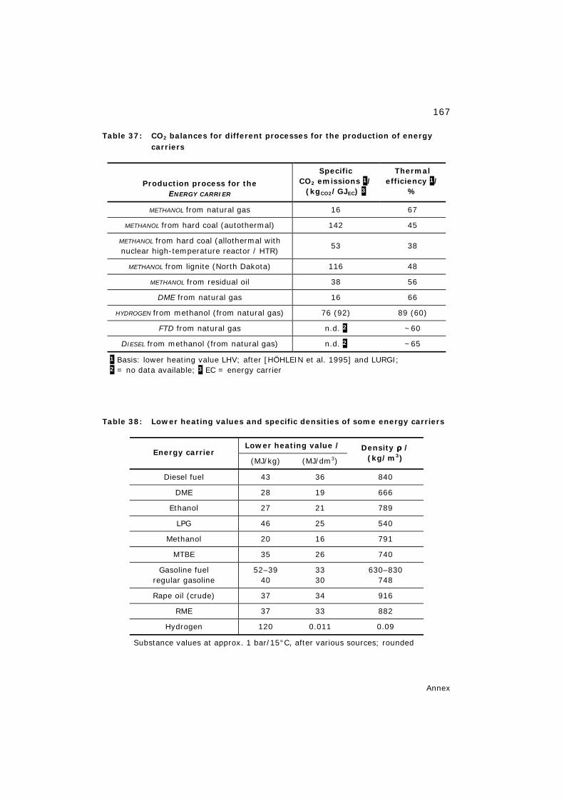
167
Annex
Table 37: CO2 balances for different processes for the production of energy carriers
Production process for the ENERGY CARRIER
Specific CO2 emissions 1/
(kgCO2/GJEC) 3
Thermal efficiency 1/
%
METHANOL from natural gas 16 67 METHANOL from hard coal (autothermal) 142 45
METHANOL from hard coal (allothermal with nuclear high-temperature reactor / HTR) 53 38
METHANOL from lignite (North Dakota) 116 48 METHANOL from residual oil 38 56
DME from natural gas 16 66
HYDROGEN from methanol (from natural gas) 76 (92) 89 (60)
FTD from natural gas n.d. 2 ~60
DIESEL from methanol (from natural gas) n.d. 2 ~65
1 Basis: lower heating value LHV; after [HÖHLEIN et al. 1995] and LURGI; 2 = no data available; 3 EC = energy carrier
Table 38: Lower heating values and specific densities of some energy carriers
Lower heating value / Energy carrier
(MJ/kg) (MJ/dm3)
Density ρ / (kg/m3)
Diesel fuel 43 36 840
DME 28 19 666
Ethanol 27 21 789
LPG 46 25 540
Methanol 20 16 791
MTBE 35 26 740
Gasoline fuel regular gasoline
52–39 40
33 30
630–830 748
Rape oil (crude) 37 34 916
RME 37 33 882
Hydrogen 120 0.011 0.09
Substance values at approx. 1 bar/15°C, after various sources; rounded
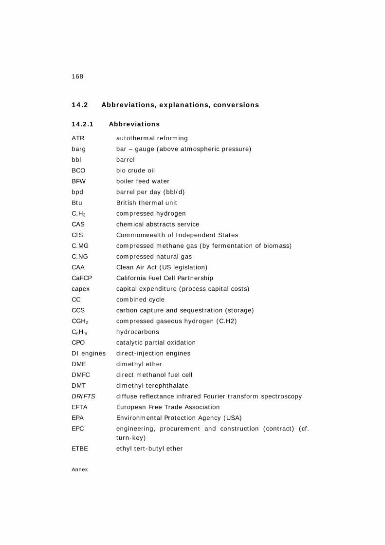
168
Annex
14.2 Abbreviations, explanations, conversions
14.2.1 Abbreviations
ATR autothermal reforming
barg bar – gauge (above atmospheric pressure)
bbl barrel
BCO bio crude oil
BFW boiler feed water
bpd barrel per day (bbl/d)
Btu British thermal unit
C.H2 compressed hydrogen
CAS chemical abstracts service
CIS Commonwealth of Independent States
C.MG compressed methane gas (by fermentation of biomass)
C.NG compressed natural gas
CAA Clean Air Act (US legislation)
CaFCP California Fuel Cell Partnership
capex capital expenditure (process capital costs)
CC combined cycle
CCS carbon capture and sequestration (storage)
CGH2 compressed gaseous hydrogen (C.H2)
CnHm hydrocarbons
CPO catalytic partial oxidation
DI engines direct-injection engines
DME dimethyl ether
DMFC direct methanol fuel cell
DMT dimethyl terephthalate
DRIFTS diffuse reflectance infrared Fourier transform spectroscopy
EFTA European Free Trade Association
EPA Environmental Protection Agency (USA)
EPC engineering, procurement and construction (contract) (cf. turn-key)
ETBE ethyl tert-butyl ether
169
Annex
EU15 European Union with 15 member states
EUCAR European Council for Automotive R&D
EXAFS extended X-ray absorption fine structure
FAME fatty acid methyl ester (biodiesel)
FC fuel cell
FFC full fuel cycle
FFV flexible fuel vehicle
FOB free on board (Rotterdam)
FT Fischer-Tropsch (synthesis)
FT-d Fischer-Tropsch diesel
GNP gross national product
GT gas turbine
GTL gas-to-liquids (conversion process for gaseous to liquid energy carriers)
HHV higher heating value (basis)
HMI Hahn-Meitner Institute
HTFC high-temperature fuel cell
HTAS Haldor Topsøe A/S
HTS high temperature shift (reactor)
ICE internal combustion engine
IGCC integrated gasification combined cycle
IR infrared
L.H2 liquid hydrogen
LHV lower heating value
LNG liquified natural gas
LPG liquified petroleum gas (propane/butane mixture)
LTFC low-temperature fuel cell
LTS low-temperature shift (reactor)
M100 fuel with 100% methanol
M15 fuel with 15% methanol + 85% gasoline
M85 fuel with 85% methanol + 15% gasoline
MEK methyl ethyl ketones
MeOH methanol
MFC multi-fuel concept
170
Annex
MFCA Methanol Fuel Cell Alliance
MFV multi-fuel vehicle
MMA methyl methacrylate
MON motor octane number
MSAT mobile source air toxics
MT metric tons
MTBE methyl tert-butyl ether
MTG methanol to gasoline
MTO methanol to olefins
MTPD metric tons per day
NG natural gas
NHE normal hydrogen electrode
NMHC non-methane hydrocarbons (without solvent)
NMOG non-methane organic gases
NOx nitrogen oxide
opex operating expenditure (process operating costs)
PADD petroleum administration for defense district
PEFC polymer electrolyte fuel cell (fuel cell with a polymer membrane as the electrolyte)
PET polyethylene terephthalate
PME palm (oil) methyl ester
POX partial oxidation
PSA pressure swing adsorption
psi pounds per square inch
PZEV partial zero-emission vehicle (US/CA standard)
RME rape (oil) methyl ester
ROI return on investment
RON research octane number
RVP Reid vapour pressure
S/C steam to carbon (ratio)
SAPO silicoaluminophosphate catalysts
SMR steam methane reformer / reforming
SNG substitute natural gas
SOFC solid oxide fuel cell (HTFC with solid electrolyte)
171
Annex
synfuel synthetic fuel
SunFuel® synthetic fuel on the basis of regenerative biomass
(® trademark of Volkswagen AG)
syngas synthesis gas
tce tons of coal equivalent
TDS thermal desorption spectroscopy
TEM transmission electron microscopy
TES Transport Energy Strategy
TIGAS Topsøe integrated methanol/DME and gasoline synthesis
toe tons of oil equivalent
TPD temperature-programmed desorption
UHV ultra-high vacuum
ZEV zero-emission vehicle (US/CA standard)
14.2.2 Definitions / explanations
alkanes
saturated acyclic hydrocarbons (CnH2n+2)
alkenes unsaturated acyclic hydrocarbons (CnH2n)
APU auxiliary power unit (power supply that is independent of the drive unit of a vehicle; electric power generator (e.g.) with HTFC and diesel fuel)
ARA area natural gas; Antwerp, Rotterdam, Amsterdam; delivery place Rotterdam; trading place and hub / interconnector: Zeebrugge/B
associated gas gas produced in oil extraction; may be vented or flared
blend addition/admixture
carbon conversion rate the ratio of the number of produced moles of CH3OH to the number of consumed moles (CO + CO2)
172
Annex
catalytic conversion water-gas shift reaction
cetane number measure of the ignition quality of fuels for diesel engines
combined cycle (CC): a gas turbine (GT) in a power station is used to generate electricity, and the waste heat from the GT is used to pro-duce steam to generate additional electricity via a steam turbine
converter feed the mixture of make-up gas and recycle gas.
dehydrogenation extracting hydrogens (from a chemical compound)
E5 ethanol as a blend component
EPA Region Classification of US states and territories into 10 regions [EPA 2006] Region 1: Connecticut, Maine, Massachusetts, New Hampshire, Rhode Island, Vermont. Region 2: Commonwealth of Puerto Rico, New Jersey, New York, U.S. Virgin Islands. Region 3: Delaware, District of Columbia, Maryland, Pennsylvania, Virginia, West Virginia. Region 4: Alabama, Florida, Georgia, Kentucky, Mississippi, North Carolina, South Carolina, Tennessee. Region 5: Illinois, Indiana, Michigan, Minnesota, Ohio, Wisconsin. Region 6: Arkansas, Louisiana, New Mexico, Oklahoma, Texas. Region 7: Iowa, Kansas, Missouri, Nebraska. Region 8: Colorado, Montana, North Dakota, South Dakota, Utah, Wyoming. Region 9: American Samoa, Arizona, California, Commonwealth of the Northern Mariana Islands,Guam, Hawaii, Nevada. Region 10: Alaska, Idaho, Oregon, Washington.
173
Annex
EU15 15 member states of the European Union (up to 2003): Austria, Belgium, Denmark, Finland, France, Germany, Greece, Ireland, Italy, Luxembourg, Netherlands, Portugal, Spain, Sweden, United Kingdom.
EU25 EU15 +10 new EU candidate countries (from 2004): Cyprus, Czech Republic, Estonia, Hungary, Latvia, Lithuania, Malta, Poland, Slovakia, Slovenia
European Free Trade Association (EFTA) 7 EFTA member states (up to 1995): Austria, Finland, Iceland, Liechtenstein, Norway, Sweden, Switzerland. 4 EFTA member states (from 1995): Iceland, Liechtenstein, Norway, Switzerland (non-EU members), 3 member states to the EU (from 1995): Austria, Finland, Sweden
FFC full fuel cycle from primary energy carrier to end use
flaring of natural gas: natural gas typically associated at oil fields
grade AA methanol cf. Table 8
green field natural gas (well) – methanol production (balance ± 0) – ship
heavy feedstock cf. heavy natural gas
heavy natural gas natural gas with high content of higher hydrocarbons
Henry coefficient dimensionless quotient of the molar concentration in the gas and water phase; strictly speaking, only applies to substan-ces with low water solubility and ideal behaviour in the sense of the gas laws; in ecochemistry, measure of the volatility of a chemical from water at a given temperature [ROEMPP 2003] (examples cf. Table 24).
HTER Haldor Topsøe Exchanger Reformer; installation in parallel (-p) or series (-s) with the autothermal reformer
174
Annex
hub grid node; here: for natural gas pipelines
integrated gasification combined cycle (IGCC): the GT in a CC power station is fired on a gas fuel derived from the gasification of liquid or solid carbonaceous materi-als
interconnector natural gas pipeline between the European Continent (Zeebrugge/B) and the British Isles (Bacton/England)
light feedstock cf. light natural gas
light natural gas natural gas with low content of higher hydrocarbons
low grade methanol cf. Table 8
M3 methanol as a blend component (gasoline blend)
make-up gas the synthesis gas passing from the synthesis gas prepara-tion section to the synthesis loop
Methanol-to-Shift™ Haldor Topsoe AS trademark
module M the methanol synthesis gas is characterised by the stoichiometric ratio M = (H2-CO2)/(CO+CO2)
naphtha special petroleum / petroleum fractions in cracking and distillation; most important raw material source in petro-chemistry
octane number measure of the anti-knock properties of fuels for gasoline engines
olefins alkenes
PADD Classification of US states into 5 districts (definition since World War II) [EIA 2004]
175
Annex
PADD 1: Connecticut, Delaware, District of Columbia, Flor-ida, Georgia, Maine, Maryland, Massachusetts, New Hamp-shire, New Jersey, New York, North Carolina, Pennsylvania, Rhode Island, South Carolina, Vermont, Virginia, West Vir-ginia. PADD 2: Illinois, Indiana, Iowa, Kansas, Kentucky, Michigan, Minnesota, Missouri, Nebraska, North Dakota, Ohio, Okla-homa, South Dakota, Tennessee, Wisconsin. PADD 3: Alabama, Arkansas, Louisiana, Mississippi, New Mexico, Texas PADD 4: Colorado, Idaho, Montana, Utah, Wyoming PADD 5: Alaska, Arizona, California, Hawaii, Nevada, Ore-gon, Washington
premium power highest-quality power supply
purge gas the gas withdrawn from the synthesis loop to remove excess reactants (mainly hydrogen) and to prevent build-up of in-erts (mainly methane, nitrogen, and argon).
recycle gas the gas which is returned to the synthesis reactor after separation of raw product in the product separator
reformulated gasoline "improved" gasoline; free of sulphur; with MTBE addition; not precisely defined, modified compositions (USA); purpose: reduction of pollutant emissions
Reid vapour pressure standardized measuring procedure in the USA for the vapour pressure of a liquid; in pounds per square inch (psi) at 100 °F
remote gas (also: stranded gas); gas deposit too remote; transport as gas uneconomical; accounts for 80% of worldwide proven reserves [IAEE 2003] (cf. also: Oil, Gas and Energy/OGEL; http://www.gasandoil. com)
reserves developed energy carrier deposits
176
Annex
resources non-developed energy carrier deposits
sequestration selective separation of CO2 and long-term storage (of carbon)
stranded gas cf. remote gas
stranded natural gas natural gas at remote locations
teratogenic effects causing malformations
turn-key the supplier must construct and hand over the complete plant ready for operation. All supplies and services belong to his scope of work. He guarantees completion according to schedule and warrants the quality. Within these limits he is relatively free.
UPS uninterruptible power supply
well-to-wheels analyses balance of full fuel cycle (FFC) and emission chains (CO2) for passenger car operation including fuel supply
14.2.3 Chemical compounds
acetic acid (CH3COOH, C2H4O2)
carbon dioxide (CO2)
carbon monoxide (CO)
diesel fuel (~ C13H24, [ROEMPP 2003])
dimethyl ether (H3COH3C, C2H6O)
dimethyl terephthalate, DMT (CH3O-CO-C6H4-COOCH3, C10H10O4)
ethanol (C2H5OH, C2H6O)
ethyl tert-butyl ether, ETBE (C6H14O)
formaldehyde (CHOH, CH2O)
formic acid (HCOOH, CH2O2)
glycerol (CH2OH-CHOH-CH2OH, C3H8O3).
hydrogen (H2)
177
Annex
isobutene (C4H8)
methane (CH4)
methanol (CH3OH, CH4O)
methyl methacrylate, MMA (CH2C(CH3)CO2CH3, C5H8O2)
methyl tert-butyl ether, MTBE (C5H12O)
polyethylene terephthalate, PET (C10H8O4)n
rape oil (~ C57H101.6O6, [ROEMPP 2003])
rape oil methyl ester (~ C19H35.2O2, [ROEMPP 2003])
14.2.4 Specification of quantities
1 million = 106
1 t/d = 1 ton per day
1 t/y = 1 ton per year
ppmv = ppm (volume)
ppmw = ppm (weight, mass)
14.2.5 Conversion of units
1 bar = 105 Pa
1 bbl = 158.9873 litres
1 GJ = (100/0.36) kWh
1 mbar = 1 hPa
10 mbar = 1 kPa
1 million tce = 29.308 PJ (LHV)
1 MMBtu = 1.055056 GJ
1 psi = 6.89476 kPa
1 toe = 41.868 GJ (LHV)
t/°F = (t/°C ∗ 1.8) + 32
14.2.6 Estimation of units
1 MMBtu ≈ 1 GJ
1 US$ ≈ 1 € (mid-2003)
1 US$/MMBtu ≈ 1 €/GJ
178
Keywords
15 Keywords
acetic acid............................................................................118, 119
agriculturally usable area ..............................................................125
analysis
tank-to-wheel .............................................................................24
well-to-tank................................................................................24
well-to-wheels....................................................................... 22, 24
ARA quotations ............................................................................121
autothermal reforming ....................................................................50
hydrogen recovery.......................................................................63
module adjustment......................................................................63
biomass
available potential .....................................................................128
gasification ...............................................................................126
storability .................................................................................128
transportability..........................................................................128
biomass projects
CHOREN...................................................................................135
ReFuelNet.................................................................................135
biomethanol ................................................................................126
California Fuel Cell Partnership .........................................................34
carbon conversion rate....................................................................38
catalyst
acid function ...............................................................................81
copper-based ..............................................................................81
dual-function ........................................................................ 78, 79
CO2
multiple use................................................................................36
sequestration ......................................... 2, 36, 41, 42, 43, 45, 46, 51
storage ......................................................................................45
coal
conversion..................................................................................46
179
Keywords
gasification ........................................................................... 42, 46
costs
investment .................................................................................39
study comparison ........................................................................40
diesel .........................................................................................105
dimethyl terephthalate ..................................................................118
DME .............................................................................................15
clean fuel ...................................................................................76
power generation ........................................................................96
production ..................................................................................97
DMFC ...........................................................................................22
battery replacement.....................................................................34
catalyst degradation ....................................................................31
catalyst loading ...........................................................................30
costs..........................................................................................30
direct conversion .........................................................................26
electrochemical reactions..............................................................27
electrodes ..................................................................................27
emergency power generator........................................................137
hybrid drive ................................................................................33
MEA...........................................................................................31
membrane electrode assembly ......................................................27
membrane humidification .............................................................28
membranes
drag coefficient.........................................................................32
fluorine-free.............................................................................31
methanol permeability ...............................................................32
Nafion .....................................................................................31
PEK.........................................................................................31
sulphonated .............................................................................31
swelling...................................................................................32
mixed potentials..........................................................................32
operating temperature .................................................................28
overvoltage ................................................................................26
180
Keywords
performance target ......................................................................30
portables..................................................................................137
power density .............................................................................28
voltage losses .............................................................................32
vs. lithium/ion battery..................................................................28
water management......................................................................30
downstream processes....................................................................89
dual use of reserves .......................................................................16
emissions
CO.............................................................................................17
CO2 ..................................................................................... 22, 23
regulated....................................................................................22
specific ....................................................................................... 9
Energy Bill of 2005 .......................................................................139
EPA Region..................................................................................172
feedstock ......................................................................................90
Fischer-Tropsch................................ 2, 9, 23, 24, 45, 91, 102, 126, 135
flexible fuel vehicles.............................................................10, 18, 19
formaldehyde ..............................................................................119
fuel cell
power train.................................................................................21
powered vehicles .........................................................................22
systems ...................................................................................128
fuel gas ......................................................................................104
fuel supply (full fuel cycle).............................................. 2, 23, 24, 176
fuels
alternative................................................................................125
from energy crops ................................. 125, 126, 129, 130, 131, 133
from synthesis gases..................................................................... 9
gaseous .....................................................................................26
GTL ...........................................................................................14
liquid .........................................................................................26
LPG .........................................................................................104
M15...........................................................................................17
181
Keywords
M85...........................................................................................18
renewable ................................................................................126
synfuels .....................................................................................45
synfuels, SunFuel®....................................................................... 3
synthetic liquid............................................................................. 3
Future Gen Program .......................................................................47
gas
associated .......................................................................... 16, 103
flared................................................................................. 16, 103
make-up ..................................................................................174
purge.......................................................................................175
recycle .....................................................................................175
remote............................................................................... 16, 175
stranded ............................................................................ 16, 176
vented .......................................................................................16
gas to liquids ......................................................................... 44, 102
gasoline ......................................................................................104
from coal....................................................................................41
reformulated.............................................................................118
Henry coefficient ............................................................. 17, 111, 138
hydrogen
demand ...................................................................................100
economy .............................................................................. 44, 45
from biomass............................................................................130
from coal....................................................................................46
from methanol, DME ....................................................................80
from natural gas..........................................................................45
on-board production ....................................................................21
production .......................................................................... 45, 100
storage ......................................................................................21
hydrogen plant
hydrogen purification ...................................................................83
peak shaving operation ................................................................85
recovery unit ..............................................................................94
182
Keywords
revamp ......................................................................................82
steam to carbon ratio...................................................................83
IGCC
gasification pressure ....................................................................46
power plant ................................................................................46
side products ..............................................................................47
infrastructures (methanol, hydrogen) ................................................. 3
interconnector .............................................................................174
investment costs.............................................................................96
kerosene.....................................................................................105
MCFC
bivalent operation......................................................................141
Hot Module ...............................................................................140
internal reforming......................................................................141
methanol prereformer ................................................................142
methanol-operated ....................................................................139
working temperatures ................................................................140
methanol
availability................................................................................... 5
boom.......................................................................................... 4
change of supply flow.................................................................... 5
chemical base material .................................................................. 3
costs..........................................................................................96
crude .........................................................................................39
engine .......................................................................................18
fire hazard................................................................................110
for fuel cell power trains ...............................................................15
for internal combustion engines .....................................................15
from biomass............................................................................125
fuel grade............................................................................. 14, 66
grade AA .........................................................................14, 37, 75
gross national product............................................................ 4, 119
investments................................................................................. 5
low grade ...................................................................................74
183
Keywords
megaplant ................................................................. 4, 16, 40, 144
miscibility .................................................................................111
odour threshold.........................................................................110
plant design................................................................................59
price in Europe..........................................................................124
pricing ........................................................................................ 4
production ..................................................................................14
properties...................................................................................10
pure ..........................................................................................95
raw............................................................................................67
single-line plants .........................................................................95
specifications ..............................................................................37
substitution product ...................................................................... 3
synthesis.............................................................................. 36, 92
high-pressure...........................................................................68
inerts ......................................................................................68
low-pressure ............................................................................68
shift reaction............................................................................69
surface species (formyl, methoxy, formate)..................................69
to gasoline............................................................................ 42, 45
to propylene .............................................................................104
toxicity................................................................. 26, 111, 112, 115
toxicity vs. gasoline ............................................................112, 115
use............................................................................................15
Methanol Fuel Cell Alliance...............................................................34
methyl methacrylate.....................................................................118
MTBE..........................................................................................117
ban ..............................................................17, 119, 123, 124, 138
dangers to health ........................................................................17
gasoline blend.............................................................................17
lead phase-out ..........................................................................138
lead substitute ............................................................................17
leakages (pipelines, tanks) .........................................................118
octane booster ............................................................................15
184
Keywords
production .............................................................................. 3, 17
use............................................................................................17
naphtha ......................................................................................100
natural gas
conversion..................................................................................89
flaring........................................................................................45
heavy ................................................................................ 90, 173
light................................................................................... 90, 174
liquified......................................................................................45
reforming ...................................................................................38
stranded ....................................................................................44
substitute ...................................................................................46
NECAR 5 ........................................................................................ 1
oil
crops (pressing, extraction) ........................................................127
imports ....................................................................................128
maximum production .................................................................... 1
PADD..........................................................................................174
partial oxidation
catalytic .....................................................................................50
non-catalytic...............................................................................50
oxygen / air ................................................................................51
oxygen membrane.......................................................................51
oxygen plant ...............................................................................51
with oxygen................................................................................50
PEFC ...................................................................................... 20, 30
pressure swing adsorption ....................................................... 90, 101
primary energy
requirements ..............................................................................23
primary energy requirements...........................................................22
propylene.............................................................................104, 123
reforming
autothermal................................................................................38
combined ............................................................................. 38, 91
185
Keywords
technology
economy of scale ......................................................................65
selection..................................................................................59
refuelling systems (closed) ............................................................110
RME .............................................................................................16
secondary pollutants........................................................................ 9
set-aside areas ............................................................................129
SOFC with MeOH/DME
carbon formation .........................................................................85
methanator.................................................................................86
steam reforming
catalyst ......................................................................................49
convective ..................................................................................61
H2/CO ratio.................................................................................51
of liquid hydrocarbons ..................................................................49
of methane.................................................................................48
steam to carbon ratio...................................................................48
tubular refomer ...........................................................................51
tubular reformer..........................................................................49
stoichiometric number ....................................................................90
stranded natural gas.......................................................... 45, 47, 176
synthesis gas
CO/CO2 ratio...............................................................................59
composition ................................................................................51
converter feed.............................................................................60
for methanol
H2/CO ratio ..............................................................................53
module M ................................................................................53
from natural gas, coal, biomass ...................................................... 3
hydrogen as an inert ....................................................................60
hydrogen recycling ......................................................................54
inerts.........................................................................................59
make-up gas...............................................................................60
module M ...................................................................................52
186
Keywords
plant costs..................................................................................51
production ..................................................................................36
production, use ...........................................................................44
properties...................................................................................51
purge gas...................................................................................60
recycle gas .................................................................................60
scale of operation ........................................................................54
stoichiometry ..............................................................................59
unit costs ...................................................................................89
toxicity
methanol, gasoline, diesel.............................................................26
transesterification...........................................................................15
two-step reforming
ammonia plant concept ................................................................61
lean natural gas ..........................................................................62
methane slip ...............................................................................62
rich natural gas ...........................................................................62
Zeebrugge spot quotation..............................................................121
Schriften des Forschungszentrums Jülich Reihe Energietechnik / Energy Technology
1. Fusion Theory Proceedings of the Seventh European Fusion Theory Conference edited by A. Rogister (1998); X, 306 pages ISBN: 3-89336-219-3
2. Radioactive Waste Products 1997 Proceedings of the 3rd International Seminar on Radioactive Waste Products held in Würzburg (Germany) from 23 to 26 June 1997 edited by R. Odoj, J. Baier, P. Brennecke et al. (1998), XXIV, 506 pages ISBN: 3-89336-225-8
3. Energieforschung 1998 Vorlesungsmanuskripte des 4. Ferienkurs „Energieforschung“ vom 20. bis 26. September 1998 im Congrescentrum Rolduc und im Forschungszentrum Jülich herausgegeben von J.-Fr. Hake, W. Kuckshinrichs, K. Kugeler u. a. (1998), 500 Seiten ISBN: 3-89336-226-6
4. Materials for Advances Power Engineering 1998 Abstracts of the 6th Liège Conference edited by J. Lecomte-Beckers, F. Schubert, P. J. Ennis (1998), 184 pages ISBN: 3-89336-227-4
5. Materials for Advances Power Engineering 1998 Proceedings of the 6th Liège Conference edited by J. Lecomte-Beckers, F. Schubert, P. J. Ennis (1998), Part I XXIV, 646, X pages; Part II XXIV, 567, X pages; Part III XXIV, 623, X pages ISBN: 3-89336-228-2
6. Schule und Energie 1. Seminar Energiesparen, Solarenergie, Windenergie. Jülich, 03. und 04.06.1998 herausgegeben von P. Mann, W. Welz, D. Brandt, B. Holz (1998), 112 Seiten ISBN: 3-89336-231-2
7. Energieforschung Vorlesungsmanuskripte des 3. Ferienkurses „Energieforschung“ vom 22. bis 30. September 1997 im Forschungszentrum Jülich herausgegeben von J.-Fr. Hake, W. Kuckshinrichs, K. Kugeler u. a. (1997), 505 Seiten ISBN: 3-89336-211-8
Schriften des Forschungszentrums Jülich Reihe Energietechnik / Energy Technology 8. Liberalisierung des Energiemarktes
Vortragsmanuskripte des 5. Ferienkurs „Energieforschung“ vom 27. September bis 1. Oktober 1999 im Congrescentrum Rolduc und im Forschungszentrum Jülich herausgegeben von J.-Fr. Hake, A. Kraft, K. Kugeler u. a. (1999), 350 Seiten ISBN: 3-89336-248-7
9. Models and Criteria for Prediction of Deflagration-to-Detonation Transition (DDT) in Hydrogen-Air-Steam-Systems under Severe Accident Conditions edited by R. Klein, W. Rehm (2000), 178 pages ISBN: 3-89336-258-4
10. High Temperature Materials Chemistry Abstracts of the 10th International IUPAC Conference, April 10 - 14 2000, Jülich edited by K. Hilpert, F. W. Froben, L. Singheiser (2000), 292 pages ISBN: 3-89336-259-2
11. Investigation of the Effectiveness of Innovative Passive Safety Systems for Boiling Water Reactors edited by E. F. Hicken, K. Verfondern (2000), X, 287 pages ISBN: 3-89336-263-0
12. Zukunft unserer Energieversorgung Vortragsmanuskripte des 6. Ferienkurs „Energieforschung“ vom 18. September bis 22. September 2000 im Congrescentrum Rolduc und im Forschungszentrum Jülich herausgegeben von J.-Fr. Hake, S. Vögele, K. Kugeler u. a. (2000), IV, 298 Seiten ISBN: 3-89336-268-1
13. Implementing Agreement 026 For a programme of research, development and demonstration on advances fuel cells Fuel Cell Systems for Transportation Annex X. Final Report 1997 - 1999 edited by B. Höhlein; compiled by P. Biedermann (2000), 206 pages ISBN: 3-89336-275-4
14. Vorgespannte Guß-Druckbehälter (VGD) als berstsichere Druckbehälter für innovative Anwendungen in der Kerntechnik Prestressed Cast Iron Pressure Vessels as Burst-Proof Pressure Vessels for Innovative Nuclear Applications von W. Fröhling, D. Bounin, W. Steinwarz u. a. (2000) XIII, 223 Seiten ISBN: 3-89336-276-2
Schriften des Forschungszentrums Jülich Reihe Energietechnik / Energy Technology 15. High Temperature Materials Chemistry
Proceedings of the 10th International IUPAC Conference held from 10 to 14 April 2000 at the Forschungszentrum Jülich, Germany Part I and II edited by K. Hilpert, F. W. Froben, L. Singheiser (2000), xvi, 778, VII pages ISBN: 3-89336-259-2
16. Technische Auslegungskriterien und Kostendeterminanten von SOFC- und PEMFC-Systemen in ausgewählten Wohn- und Hotelobjekten von S. König (2001), XII, 194 Seiten ISBN: 3-89336-284-3
17. Systemvergleich: Einsatz von Brennstoffzellen in Straßenfahrzeugen von P. Biedermann, K. U. Birnbaum, Th. Grube u. a. (2001), 185 Seiten ISBN: 3-89336-285-1
18. Energie und Mobilität Vorlesungsmanuskripte des 7. Ferienkurs „Energieforschung“ vom 24. September bis 28. September 2001 im Congrescentrum Rolduc und im Forschungszentrum Jülich herausgegeben von J.-Fr. Hake, J. Linßen, W. Pfaffenberger u. a. (2001), 205 Seiten ISBN: 3-89336-291-6
19. Brennstoffzellensysteme für mobile Anwendungen von P. Biedermann, K. U. Birnbaum, Th. Grube u. a. (2002) PDF-Datei auf CD ISBN: 3-89336-310-6
20. Materials for Advances Power Engineering 2002 Abstracts of the 7th Liège Conference edited by J. Lecomte-Beckers, M. Carton, F. Schubert, P. J. Ennis (2002), c. 200 pages ISBN: 3-89336-311-4
21. Materials for Advanced Power Engineering 2002 Proceedings of the 7th Liège Conference Part I, II and III edited by J. Lecomte-Beckers, M. Carton, F. Schubert, P. J. Ennis (2002), XXIV, 1814, XII pages ISBN: 3-89336-312-2
22. Erneuerbare Energien: Ein Weg zu einer Nachhaltigen Entwicklung? Vorlesungsmanuskripte des 8. Ferienkurs „Energieforschung“ vom 23. bis 27. September 2002 in der Jakob-Kaiser-Stiftung, Königswinter herausgegeben von J.-Fr. Hake, R. Eich, W. Pfaffenberger u. a. (2002), IV, 230 Seiten ISBN: 3-89336-313-0
Schriften des Forschungszentrums Jülich Reihe Energietechnik / Energy Technology 23. Einsparpotenziale bei der Energieversorgung von Wohngebäuden durch
Informationstechnologien von A. Kraft (2002), XII, 213 Seiten ISBN: 3-89336-315-7
24. Energieforschung in Deutschland Aktueller Entwicklungsstand und Potentiale ausgewählter nichtnuklearer Energietechniken herausgegeben von M. Sachse, S. Semke u. a. (2002), II, 158 Seiten, zahlreiche farb. Abb. ISBN: 3-89336-317-3
25. Lebensdaueranalysen von Kraftwerken der deutschen Elektrizitäts-wirtschaft von A. Nollen (2003), ca. 190 Seiten ISBN: 3-89336-322-X
26. Technical Session: Fuel Cell Systems of the World Renewable Energy Congress VII Proceedings edited by D. Stolten and B. Emonts (2003), VI, 248 pages ISBN: 3-89336-332-7
27. Radioactive Waste Products 2002 (RADWAP 2002) Proceedings edited by R. Odoj, J. Baier, P. Brennecke and K. Kühn (2003), VI, 420 pages ISBN: 3-89336-335-1
28. Methanol als Energieträger von B. Höhlein, T. Grube, P. Biedermann u. a. (2003), XI, 109 Seiten ISBN: 3-89336-338-6
29. Hochselektive Extraktionssysteme auf Basis der Dithiophosphinsäuren: Experimentelle und theoretische Untersuchungen zur Actinoiden(III)-Abtrennung von S. A. H. Nabet (2004), VI, 198 Seiten ISBN: 389336-351-3
30. Benchmarking-Methodik für Komponenten in Polymerelektrolyt-Brenn-stoffzellen von Matthias Gebert (2004), 194 Seiten ISBN: 3-89336-355-6
31. Katalytische und elektrochemische Eigenschaften von eisen- und kobalt-haltigen Perowskiten als Kathoden für die oxidkeramische Brennstoffzelle (SOFC) von Andreas Mai (2004), 100 Seiten ISBN: 3-89336-356-4
Schriften des Forschungszentrums Jülich Reihe Energietechnik / Energy Technology 32. Energy Systems Analysis for Political Decision-Making
edited by J.-Fr. Hake, W. Kuckshinrichs, R. Eich (2004), 180 pages ISBN: 3-89336-365-3
33. Entwicklung neuer oxidischer Wärmedämmschichten für Anwendungen in stationären und Flug-Gasturbinen von R. Vaßen (2004), 141 Seiten ISBN: 3-89336-367-X
34. Neue Verfahren zur Analyse des Verformungs- und Schädigungsverhaltens von MCrAlY-Schichten im Wärmedämmschichtsystem von P. Majerus (2004), 157 Seiten ISBN: 3-89336-372-6
35. Einfluss der Oberflächenstrukturierung auf die optischen Eigenschaften der Dünnschichtsolarzellen auf der Basis von a-Si:H und µc-Si:H von N. Senoussaoui (2004), 120 Seiten ISBN: 3-89336-378-5
36. Entwicklung und Untersuchung von Katalysatorelementen für innovative Wasserstoff-Rekombinatoren von I.M. Tragsdorf (2005), 119 Seiten ISBN: 3-89336-384-X
37. Bruchmechanische Untersuchungen an Werkstoffen für Dampfkraftwerke mit Frischdampftemperaturen von 500 bis 650°C von L. Mikulová (2005), 149 Seiten ISBN: 3-89336-391-2
38. Untersuchungen der Strukturstabilität von Ni-(Fe)-Basislegierungen für Rotorwellen in Dampfturbinen mit Arbeitstemperaturen über 700 °C von T. Seliga (2005), 106 Seiten ISBN: 3-89336-392-0
39. IWV-3 Report 2005. Zukunft als Herausforderung (2005), 115 Seiten ISBN: 3-89336-393-9
40. Integrierter Photodetektor zur Längenmessung von E. Bunte (2005), XI, 110 Seiten ISBN: 3-89336-397-1
41. Microcrystalline Silicon Films and Solar Cells Investigated by Photoluminescence Spectroscopy by T. Merdzhanova (2005), X, 137 pages ISBN: 3-89336-401-3
Schriften des Forschungszentrums Jülich Reihe Energietechnik / Energy Technology 42. IWV-3 Report 2005. Future as a challenge
(2005), 115 pages ISBN: 3-89336-405-6
43. Electron Spin Resonance and Transient Photocurrent Measurements on Microcrystalline Silicon by T. Dylla (2005), X, 138 pages ISBN: 3-89336-410-2
44. Simulation und Analyse des dynamischen Verhaltens von Kraftwerken mit oxidkeramischer Brennstoffzelle (SOFC) von M. Finkenrath (2005), IV, 155 Seiten ISBN: 3-89336-414-5
45. The structure of magnetic field in the TEXTOR-DED by K.H. Finken, S.S. Abdullaev, M. Jakubowski, M. Lehnen, A. Nicolai, K.H. Spatschek (2005), 113 pages ISBN: 3-89336-418-8
46. Entwicklung und Modellierung eines Polymerelektrolyt-Brennstoffzellenstapels der 5 kW Klasse von T. Wüster (2005), 211 Seiten ISBN: 3-89336-422-6
47. Die Normal-Wasserstoffelektrode als Bezugselektrode in der Direkt-Methanol-Brennstoffzelle von M. Stähler (2006), VI, 96 Seiten ISBN: 3-89336-428-5
48. Stabilitäts- und Strukturmodifikationen in Katalysatordispersionen der Direktmethanolbrennstoffzelle von C. Schlumbohm (2006), II, 211 Seiten ISBN: 3-89336-429-3
49. Eduktvorbereitung und Gemischbildung in Reaktionsapparaten zur autothermen Reformierung von dieselähnlichen Kraftstoffen von Z. Porš (2006), XX, 182, XII Seiten ISBN: 3-89336-432-2
50. Spektroskopische Untersuchung der poloidalen Plasmarotation unter dem Einfluß statischer und dynamischer Ergodisierung am Tokamak TEXTOR von C. Busch (2006), IV, 81 Seiten ISBN: 3-89336-433-1
51. Entwicklung und Optimierung von Direktmethanol-Brennstoffzellstapeln von M. J. Müller (2006), 167 Seiten ISBN: 3-89336-434-X

Schriften des Forschungszentrums Jülich Reihe Energietechnik / Energy Technology 52. Untersuchung des reaktiven Sputterprozesses zur Herstellung von
aluminiumdotierten Zinkoxid-Schichten für Silizium-Dünnschichtsolarzellen von J. Hüpkes (2006), XIV, 170 Seiten ISBN: 3-89336-435-8
53. Materials for Advanced Power Engineering 2006 Proceedings of the 8th Liège Conference Part I, II and III edited by J. Lecomte-Beckers, M. Carton, F. Schubert, P. J. Ennis (2006), Getr. Pag. ISBN: 3-89336-436-6
54. Verdampfung von Werkstoffen beim Betrieb von Hochtemperaturbrennstoffzellen (SOFC) von M. Stanislowski (2006), IV, 154 Seiten ISBN: 3-89336-438-2
55. Methanol as an Energy Carrier edited by P. Biedermann, Th. Grube, B. Höhlein (2006), XVII, 186 Seiten ISBN: 3-89336-446-3

EnergietechnikEnergy Technology
Band / Volume 55ISBN 3-89336-446-3