metallurgical factors that affect the strand width during ... continuous slab casting process, the...
TRANSCRIPT
Transaction
Paper
▲473The Journal of The South African Institute of Mining and Metallurgy VOLUME 105 REFEREED PAPER AUGUST 2005
Introduction
1.4003 is 11 to 12 per cent chromium steelthat exists in the ferrite-austenite dual phasearea of the Fe-Cr binary phase diagram attemperatures between 850˚C and 1250˚C, andat temperatures higher than 1250˚C, this steel
is generally fully ferritic1. 1.4003 stainlesssteel is produced by Columbus Stainless(Middelburg, South Africa) using the straightmould, curved bow continuous slab caster. Inthis continuous slab casting process, themolten steel flows from a ladle through atundish into the mould. The molten steelfreezes against the tapered and water-cooledcopper mould with nickel coating on the hotfaces to form a solid shell. When the solidifi-cation shell exits from the mould, it issubjected to ferrostatic pressure exerted by thecolumn of the liquid steel inside the strand.The most vulnerable are the unconstrainedside walls (narrow faces) of the strand, hence,the side bulging effect; see Figure 1. Previousstudies2,3 have shown that the solidificationshell growth rate of the narrow side walls ofthe strand is dependent on the mould fluxproperties, casting speed and mould taperangle, among other factors.
Due to the complexity of the industrialcontinuous casting operation, it is practicallyimpossible to measure the surface temper-atures continuously after exiting from themould during the continuous casting process.The temperature profile is, therefore, modelledusing an energy balance approach that isbased on the heat transfer equations usingparameters measured from the plant directly orthe laboratory. The data that was used in thiswork was acquired from an online processcontrol computer that was installed with aproprietary software package to model thesurface temperature, solidus and liquidusprofiles of the strand; see Figure 2. Themodelled solidification shell thickness as thestrand exits from the mould was compared toone deduced from the equations below4. Theequations relate the solidifying shell thicknesst to the heat flux removed at the surface of thestrand:
Metallurgical factors that affect thestrand width during continuous castingof DIN 1.4003 stainless steelby C. Siyasiya*, G.T. van Rooyen and W.E. Stumpf*
Synopsis
One of the problems that is occasionally encountered during thecontinuous casting of DIN 1.4003 stainless steel (hereafter referredto as 1.4003) is the side bulging effect, a problem that is generallyprevalent in ferritic stainless steels. This occurs because theunconstrained narrow sides of the solidification shell are not able towithstand the ferrostatic pressure once the strand has emerged fromthe mould. Coupled with side bulging, there is strand widthvariation at high temperatures, i.e. when the steel is in the ferrite-austenite dual phase region. Both of these dimensional changes tothe slab profile create some processing problems in subsequent hotrolling operations when unacceptable width variations areencountered.
The strength of the solidification shell and its ability towithstand the ferrostatic pressure during continuous casting isdependent on its thickness and phase composition when exitingfrom the mould up to a few metres downstream. From the study ofthe high temperature metallurgical behaviour of this steel, it wasobserved that a thicker solidification shell when exiting from themould and a higher austenite volume fraction in the steel would befavourable for the reduction of the side bulging effect duringcontinuous casting. It was also found that as long as the d-ferrite toaustenite phase ratio keeps fluctuating due to variations inchemical composition and process control in the dual phase regionfrom cast to cast, the strand width variation problem wouldprobably persist. The remedy to this effect lies in more strictchemical composition and process control during continuous castingof this steel.
The hot ductility experiments revealed that 1.4003 exhibits goodhot ductility in the strand straightening temperature range with aminimum of 75 per cent reduction in area and this was attributed tothe high volume fraction of ferrite (0.2 to 0.4) in the steel. Thiswould provide a remedy to side bulging by increasing the secondarycooling rate of the strand in order to form a thicker solidificationshell without necessarily risking transverse cracking and othersurface defects during unbending.
Keywords: side wall bulging, resistance bending moment,applied bending moment, ferrostatic pressure.
* Department of Materials Science and MetallurgicalEngineering of the University of Pretoria.
© The South African Institute of Mining andMetallurgy, 2005. SA ISSN 0038–223X/3.00 +0.00. Paper received Nov. 2004; revised paperreceived May 2005.

Metallurgical factors that affect the strand width
[1]
[2]
[3]
where q is the average heat flux density in W m-2, cp is thespecific heat capacity (representing the enthalpy loss of thesolid shell) in J kg-1 K-1, ∆Hf is the enthalpy of solidificationin J kg-1, Lm is the height of the mould in contact with thestrand in m, vc is the average casting speed in m min-1, fp isthe exponential decrease of the local heat flux density in thecasting direction, A is the heat flux density at the meniscus inW m-2 (m min-1)-0.56, α is the slope of the log of heat fluxdensity versus distance from the meniscus in the castingdirection in mm-1, β is the slope of log of heat flux densityversus the casting speed and ρ is the density of the solid shellin kg m-3.
Applying values and constants determined bySchwerdtfeger et al.4 for a continuous slab caster, i.e. ∆Hf =262000 J kg-1, cp = 750 J kg-1 K-1, γ = 32 W K-1 m-1, ρ = 7
500 kg m-3, α = 0.0015 mm-1; and for Lm = 0.7 m, β = 0.56,vc = 1.01 m min-1, the shell thickness as the strand exitsfrom the mould would be 15 mm and from the plant model, itwas 14.1 mm. There is, therefore, not much disparitybetween the two predictions and this validates the continuouscasting plant model.
In order to assess the ability of the solidification shell towithstand the ferrostatic pressure during continuous casting,the hot strength of the modelled solidification shell wasexamined and compared with the plastic bending of the sidewalls of the solidification shell induced by the ferrostaticpressure.
Previous studies5,6 have shown that an austenitic solidifi-cation shell is generally stronger than a ferritic one and,therefore, it is not surprising that the side bulging problem ismore prevalent in ferritic than austenitic stainless steels.Hence, the influence of the chemical composition (additionsof austenite formers) on the δ-ferrite to austenite phasechange was also investigated.
Experimental techniques
The as-cast 1.4003 with the following chemical compositionFe-0.014C-0.0155N-0.4Ni-0.65Mn-11.28Cr-0.65Si-0.025Ti-0.08V was reheated to 1360°C and soaked for 10 minutes
qAv
Lec
m
Lm= −( )−β
α
α1
fL e
eqm
L
L
m
m=
−
−
−
α α
α1
tH
f c q
H
f c q
L
f c vf
q p
f
q p
m
q p c
= +
+
λ λ λρ
∆ ∆2
2
▲
474 AUGUST 2005 VOLUME 105 REFEREED PAPER The Journal of The South African Institute of Mining and Metallurgy
Figure 1—(a) Section of a continuous cast slab for 1.4003 showing side bulging defect on the narrow face of the 200 mm thick continuously cast slab.(b) Schematic presentation of the side bulging of the narrow face of the strand
Figure 2—A typical modelled temperature profile for the surface and the centre obtained from an online data acquisition computer during continuouscasting of 1.4003
200
mm

before being cooled to the tensile test temperature in aGleeble 1500™ hot working testing machine, simulating thecooling profile during straightening in the continuous caster.The samples were deformed at a strain rate of 2.1 x 10⁻⁴ s-1
that is an order of magnitude higher than the strain rate of4.62 x 10-5 s-1 calculated from the continuous caster’sparameters. The time to deform the specimen to fracture inthe Gleeble at the strain rate in the plant would have beenunrealistically long and, therefore, not a reflection of thestraightening process itself that lasts for an average of fourminutes in the continuous caster. While one set of sampleswas deformed to fracture (to test hot ductility), the other wasdeformed to a strain equal to the deformation experiencedduring straightening, being a true strain of 11.1 x 10⁻³. Thelatter was used to assess the influence of deformation on theδ-ferrite to austenite phase transformation by comparing theresults with the deformation-free specimens that were givenonly a furnace heat treatment.
Three chemical compositions of 1.4003 withKaltenhauser ferrite factors 9.6, 11.5 and 12.1 (see Table Ibelow) were examined for the δ-ferrite to austenite transfor-mation start temperature during continuous cooling. TheKaltenhauser ferrite factor is an empirical expression that isused to predict the microstructure (ferrite volume fraction) at1000˚C, generally in weld metal and is given by7:
[4]
where the chemical compositions are in mass per cent.Two techniques were used, namely the resistivity method
and metallographic analysis. A weld simulator plus resistivitymeasuring equipment were used in the case of the resistivitymethod. A computer software program (analySIS) coupled toan optical microscope was used to measure the volumefraction.
Results and discussion
The hot ductility of 1.4003
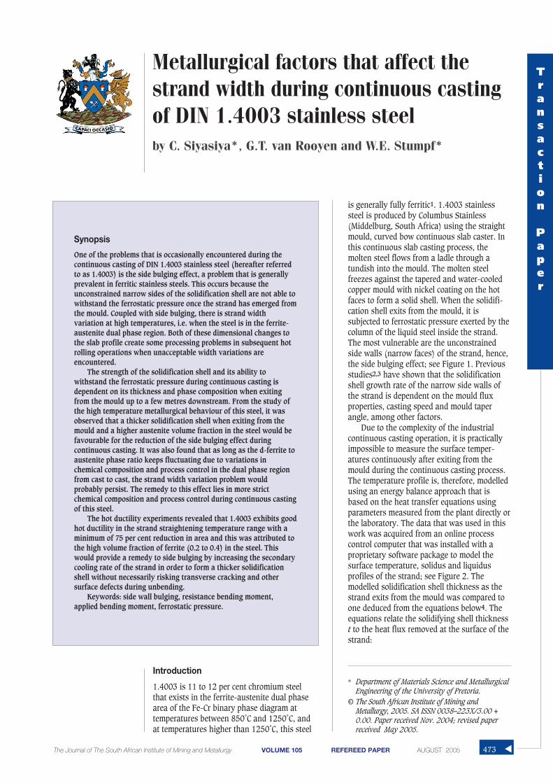
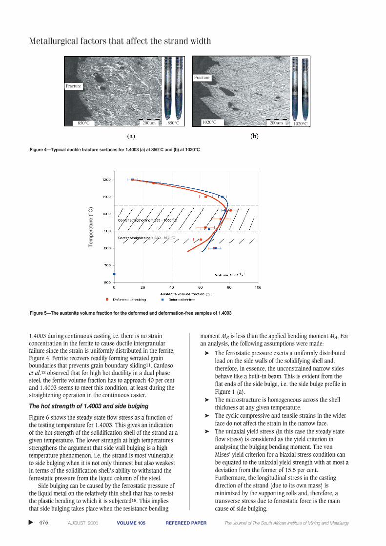
Results for the hot strength are given in Figures 3, 4 and 5. Itis evident from Figure 3 that 1.4003 has good hot ductilitywith a minimum percentage reduction in area (%RA) of 75per cent at all of the deformation temperatures tested. Figure4 is a set of micrographs of the fractured samples exhibitinga typical ductile fracture. Columbus generally experiences notransverse cracking during the continuous casting of 1.4003.This may be attributed to its good hot ductility. As may beseen from Figure 5, the austenite volume fraction increasesas the temperature decreases from above 1250°C (the δ-ferrite phase region) and starts regressing to α-ferrite below1050°C. This is typical of 11–12 per cent chromium steels8,9.Extrapolation of the two curves in Figure 5 to zero austenitevolume fraction at the upper end, would give the austenitetransformation start temperature. It may be concluded thatthe ferrite volume fraction within the straighteningtemperature region during continuous casting is about 20and 40 per cent.
The two curves in Figure 5 are almost identical and,therefore, this suggests that hot deformation does notinfluence either the δ-ferrite to austenite or the austenite toα-ferrite phase transformation. In other words, theobservation that hot deformation does not influence thekinetics of the lower temperature austenite to α-ferrite phasechange9 also holds for the higher temperature δ-ferrite toaustenite phase change in 1.4003.
In general (in both the austenitic and ferritic stainlesssteels), ferrite has good hot ductility properties and is onlydetrimental when it is present in small amounts as thin filmssurrounding the austenite grains10. The higher volumefraction of ferrite rather than a mere film along the austenitegrain boundaries is responsible for the good hot ductility of
FF Cr Si Ti Mo
Al C N Mn Ni
= + + + +
+ +( ) − −
6 8 4
2 40 2 4
Metallurgical factors that affect the strand widthTransaction
Paper
▲475The Journal of The South African Institute of Mining and Metallurgy VOLUME 105 REFEREED PAPER AUGUST 2005
Table I
The chemical composition for the 1.4003 steels that were used in the study
Heat No. C Mn Ni N Cr Si Ti V P S Mo Co FF
3387232 0.018 0.56 0.33 0.021 11.61 0.7 0.032 0.11 0.025 0.003 0.01 0.02 12.1330011 0.012 0.49 0.55 0.018 11.57 0.38 0.014 0.11 0.027 0.003 0.01 0.02 9.643316791 0.021 0.51 0.39 0.018 11.18 0.69 0.033 0.10 0.027 0.002 0.01 0.03 11.5
Figure 3—The hot ductility characteristic curves for 1.4003, ferrite factor of 11.36
Metallurgical factors that affect the strand width
1.4003 during continuous casting i.e. there is no strainconcentration in the ferrite to cause ductile intergranularfailure since the strain is uniformly distributed in the ferrite,Figure 4. Ferrite recovers readily forming serrated grainboundaries that prevents grain boundary sliding11. Cardosoet al.12 observed that for high hot ductility in a dual phasesteel, the ferrite volume fraction has to approach 40 per centand 1.4003 seems to meet this condition, at least during thestraightening operation in the continuous caster.
The hot strength of 1.4003 and side bulging
Figure 6 shows the steady state flow stress as a function ofthe testing temperature for 1.4003. This gives an indicationof the hot strength of the solidification shell of the strand at agiven temperature. The lower strength at high temperaturesstrengthens the argument that side wall bulging is a hightemperature phenomenon, i.e. the strand is most vulnerableto side bulging when it is not only thinnest but also weakestin terms of the solidification shell’s ability to withstand theferrostatic pressure from the liquid column of the steel.
Side bulging can be caused by the ferrostatic pressure ofthe liquid metal on the relatively thin shell that has to resistthe plastic bending to which it is subjected15. This impliesthat side bulging takes place when the resistance bending
moment MR is less than the applied bending moment MA. Foran analysis, the following assumptions were made:
➤ The ferrostatic pressure exerts a uniformly distributedload on the side walls of the solidifying shell and,therefore, in essence, the unconstrained narrow sidesbehave like a built-in beam. This is evident from theflat ends of the side bulge, i.e. the side bulge profile inFigure 1 (a).
➤ The microstructure is homogeneous across the shellthickness at any given temperature.
➤ The cyclic compressive and tensile strains in the widerface do not affect the strain in the narrow face.
➤ The uniaxial yield stress (in this case the steady stateflow stress) is considered as the yield criterion inanalysing the bulging bending moment. The vonMises’ yield criterion for a biaxial stress condition canbe equated to the uniaxial yield strength with at most adeviation from the former of 15.5 per cent.Furthermore, the longitudinal stress in the castingdirection of the strand (due to its own mass) isminimized by the supporting rolls and, therefore, atransverse stress due to ferrostatic force is the maincause of side bulging.
▲
476 AUGUST 2005 VOLUME 105 REFEREED PAPER The Journal of The South African Institute of Mining and Metallurgy
Figure 4—Typical ductile fracture surfaces for 1.4003 (a) at 850°C and (b) at 1020°C
Figure 5—The austenite volume fraction for the deformed and deformation-free samples of 1.4003
Tem
pera
ture
(°C
)Fracture
Fracture
1020°C850°C 1020°C850°C 200µm 200µm

➤ The elastic strain at high temperature is negligible andthat creep deformation is governed by the universal hotworking equation13:
[5]
where Q is the activation energy for hot working, R is theuniversal gas constant which is 8.31 J mol-1 K-1, n is thestress sensitivity, T is the absolute temperature, β (MPa-1) isthe stress multiplier, Z is the Zener-Hollomon parameter andA is a material constant and σσss is the steady state flow stressin MPa.
The plastic resistance bending moment MR provided bythe solidification shell would be given by:
[6]
where the yield strength σy is replaced by σss, t is the shellthickness in metres and b is the unit length along the strandin the casting direction.
Figure 7 was derived from the steady state flow stressesgiven in Figure 6 and the modelled and schematic shellthicknesses by applying Equation [6]. The resistancebending moment increases almost exponentially along thestrand. This is due to the fact that both the strength of theshell as well as the thickness increases as the strand movesdownstream. Therefore, side bulging due to ferrostaticpressure is most likely to take place just when the strandexits from the mould, where the bending strength is theleast. The ferrostatic pressure P and the plastic bendingmoment exerted on the narrow sides of the strand (referredto as the applied moment MA) are given by Equations [7] and [8] respectively.
[7]
[8a]
[8b]
[9]
where g is the acceleration due to gravity 9.81 m s-2, h is theferrostatic head in metres, ρ is the density of the liquid steel6881 kg m-3 (taking into consideration the proportions of87.5 per cent by weight iron and 11.5 per cent chromium andthe remaining 1 per cent other alloying elements), theuniformly distributed load w is the ferrostatic pressure P perunit length in N m-1 and L is the length AB of the narrowside in m, Figure 1(b) and T is the strand thickness and thatis 200 mm.
The ferrostatic pressure is zero at the meniscus of theliquid steel and reaches a maximum value just before thestrand fully solidifies. The ferrostatic bending momentincreases with ferrostatic head and decreases with thedecrease in the length AB as solidification progresses due tothe increase in thickness t. As a result, the plastic bendingmoment reaches a maximum value after which it regresses tozero as the surface area on which it acts diminishes to zerotoo when the strand is completely solid, Figure 8.
Figure 9 is a comparison of the resistance bendingmoment MR offered by the solidification shell with theapplied bending moment MA exerted by the ferrostaticpressure. As may be seen, the strand may be vulnerable toside bulging when MA is equal to or exceeded MR, Figure 9(b). This emphasizes the importance of ensuring that theunconstrained narrow sides of the strand are thick (strong)enough to withstand the ferrostatic pressure as the strandexits from the mould, Figure 9 (c). Many studies in thepast4,14–17 have related the side bulging effect to theinteraction of the strand and the mould vis-à-vis heattransfer during continuous casting. Therefore, part of thesolution to the problem of bulging lies in the study of theoptimization of the cooling rate, mould flux properties,casting speed, mould taper angle, and chemical compositionof the steel among other factors.
L T t= − 2
MwL
A = ( )2
8 simply supported beam
MwL
A = −( )2
16 built in beam
P g h= ρ
Mb t
Ry=
σ 2
4
A QRT Zss
nsinh «expβσ ε( ) = ( ) =
Metallurgical factors that affect the strand widthTransaction
Paper
▲477The Journal of The South African Institute of Mining and Metallurgy VOLUME 105 REFEREED PAPER AUGUST 2005
Figure 6—The peak strength (steady state flow stress) variation with temperature for 1.4003 obtained from the Gleeble 1500TM
Pea
k st
reng
th, (
MP
a)
Deformation temperature, (°C)

Metallurgical factors that affect the strand width
One of the assumptions that were made in this analysiswas that the phase distribution of δ-ferrite and austenite wasuniform across the solidification shell thickness. This is notnecessarily true because there is a temperature gradientbetween the outer and inner faces of the solidification shell,the inner face being close to the liquidus. As expected, theinner region of the solidification shell would be fully δ-ferritewhile the outer region δ-ferrite plus austenite. The steadystate flow stress as a function of temperature, in Figure 6,represents the surface shell strength. This implies that theexperimentally determined shell strength could be greaterthan the actual solidification shell strength during continuouscasting.
Effect of chemical composition on the austenite starttemperature Ar5
Figure 10 shows the experimentally determined continuouscooling transformation (CCT) diagram. It is evident that atcooling rates greater than 60°C/min, the δ-ferrite to austenitephase transformation becomes more sensitive to cooling rate.
This suggests that during continuous casting of 1.4003, theδ-ferrite to austenite transformation start temperature islower on the surface of the strand than at the centre of thestrand.
The slab width is measured in the temperature range of700 to 900˚C (in the δ-ferrite-austenite dual phase region, asmay be seen in the CCT diagram) as it exits from the casterand, therefore, the width variation with chemical compositionmay be ascribed to the ratio of ferrite (BCC) to austenite(FCC) and the cooling rate. Data collected from thecontinuous caster showed that a higher ferrite factor resultsin a wider slab width. Hence, it is imperative to stick tostricter chemical composition and process control in order toreduce or avert this width effect.
The results for the effect of chemical composition on theδ-ferrite to austenite transformation start temperature Ar5 aregiven in Figure 11. It is evident that austenite transformationfrom the δ-ferrite starts at earlier times as the ferrite factordecreases, i.e. as the quantity of austenite formers in the steelincreases. In fact, the austenite formers do not only shift the
▲
478 AUGUST 2005 VOLUME 105 REFEREED PAPER The Journal of The South African Institute of Mining and Metallurgy
Figure 7—The solidification shell resistance bending moment MR for the modelled shell thickness curve (solid line) and the schematic thinner and thickershell thicknesses of t (dashed line)
Figure 8—Variation of ferrostatic pressure and the applied bending moment MA with position along the strand for the built-in beam model (dashed line) andsimply supported beam (solid line). The zero position equals the meniscus of the liquid steel in the mould
Mould exit1.2t
t
0.75t
0.5t
(modelled)
Meniscus
0.0 0.2 0.4 0.6 0.8 1.0 1.2 1.4Position along the strand (m)
Res
ista
nce
bend
ing
mom
ent M
r (k
Nm
)
5
4
3
2
1
0
Mould exit
2.5
2.0
1.5
1.0
0.5
0.0
t
built-inbeam
Simplysupported
App
lied
bend
ing
mom
ent M
A(K
Nm
)
Full solid
Meniscus
0 2 4 6 8 10 12 14 16
Position along the strand (m)
Fer
rost
atic
Pre
ssur
e (k
Pa)
800
600
400
200
0

transformation temperature to earlier times during castingbut raise it as well. This is in agreement with previousstudies18 that austenite formers, particularly carbon andnitrogen, enlarge the γ-loop of the iron-chromiumequilibrium phase diagram and raise the austenite starttemperature Ar5. Figure 12 is derived from Figure 11 byplotting the austenite start temperature Ar5 against theKaltenhauser ferrite factor at the fastest and slowest coolingrates of 1500 and 30°C/min respectively. The set ofmicrographs in Figure 13 shows that increasing the quantityof austenite formers (N, C, Ni and Mn) in the steel raises theaustenite start temperature Ar5. Micrographs in Figure 13 (c)and (d) suggest that the austenite start temperature for the
relatively low ferrite factor of 9.64 is somewhere between1250°C and 1295 ˚C, i.e. somewhat higher than that of thesample with a ferrite factor of 12.1.
Conclusions
The following conclusions are made from this study:➤ The results of this study confirm that the casting
conditions within and immediately after the mouldneed to be optimized to ensure that the solidificationshell is thick enough to withstand the ferrostaticpressure exerted on the unconstrained narrow sides ofthe strand as it exits from the mould. Increasing thecooling rate as one of the significant variables may be
Metallurgical factors that affect the strand widthTransaction
Paper
▲479The Journal of The South African Institute of Mining and Metallurgy VOLUME 105 REFEREED PAPER AUGUST 2005
Figure 9—The shell resistance moment MR and ferrostatic bending moment MA versus strand position, (a) modelled, (b) and (c) schematic
Ben
ding
Mom
ent (
kNm
)B
endi
ng M
omen
t (kN
m)
Ben
ding
Mom
ent (
kNm
)

Metallurgical factors that affect the strand width
pursued with confidence as this alloy has been shownto have sufficient high temperature ductility duringunbending to eliminate the possibility of hightemperature cracking.
➤ Hot deformation appears not to affect the kinetics ofeither the δ-ferrite to austenite phase transformation orthe regression of austenite to α-ferrite undercontinuous casting conditions of 1.4003 and thetransformation kinetics in the undeformed state maybe applied with confidence to the strand duringunbending.
➤ Austenite formers (C, N, Ni and Mn) raise the δ-ferriteto austenite transformation start temperature Ar5 andshift it to earlier transformation start times duringcontinuous casting. Therefore, additions of austeniteformers within the 1.4003 specification range may befavourable for a stronger solidification shell sinceaustenite exhibits better hot strength properties than δ-ferrite.
➤ As long as the δ-ferrite to austenite phase ratio keepsfluctuating due to variations in chemical composition
within the specification range and the cooling rate inthe dual phase region from cast to cast, the strandwidth variation effect will probably persist. This is dueto the effect of different phase ratios when the strandemerges from the mould.
Acknowledgements
The cooperation, sponsorship, provision of materials andrelevant data from Columbus Stainless (Pty) Limited(Middelburg, South Africa) is greatly appreciated. Theauthors would like also to thank the Materials Science andMetallurgical Engineering Department and IMMRI of theUniversity of Pretoria for the provision of facilities andsupport that made it possible to carry out this worksuccessfully.
References1. BAKER, H. (ed.) Alloy Phase Diagrams Volume 3, ASM Handbook, 1992
pp. 1.26.
2. WOLF, M.M. Strand Surface Quality of Austenitic Stainless Steels – Part 1:Macroscopic Shell Growth and Ferrite Distribution, Ironmaking andSteelmaking, vol. 13, 1986, pp. 248–257.
▲
480 AUGUST 2005 VOLUME 105 REFEREED PAPER The Journal of The South African Institute of Mining and Metallurgy
Figure 10—The Continuous Cooling Transformation diagram for 1.4003
Figure 11—Influence of chemical composition on the measured austenite start temperature Ar5 for 1.4003 with ferrite factors of 12.1, 11.5, and 9.6
Cooling rate, (°C/min)
Martensite + ferrite
(δ+γ)
δ-ferrite Ar5
Ar4
Ar3
Ar1
Ms
Mf
Tem
pera
ture
(°C
)T
empe
ratu
re (
°C)

3. HOJO, M. et al., Effect of Mould Powder Properties on the Longitudinal Off-corner Depressions in Continuously Cast SUS304 Slabs CAMP-ISIJ 1998,862.
4. SCHWERDTFEDER, K.J. Heat Withdraw in Continuous casting of Steel TheAISE Steel Foundation, 2003, pp. 1–41.
5. RAY, S.K., MUKHOPSDHYAY, B., and DAS, P.C. Effect of chemistry on solidifi-cation and quality of stainless steel, Annual Tech. Mtg. of India Inst.Metals, Jamshedpur, Nov. 1999. pp. 14–17.
6. RAY, S.K., MUKHOPSDHYAY, B., and BHATTACHARYYA, S.K. Prediction of crack-sensitivity of concast slabs of AISI-430 stainless steel. ISIJ, vol. 36, 1996,pp. 611–612.
7. KALTENHAUSER R.H. Met. Eng. Q., May 1971, pp. 41–47.
8. KNUTSEN, R. Influence of compositional banding on grain anisotropy in3CR12 steel, Materials Science and Technology, vol. 7, 1992, pp. 621–627.
9. ZAAYMAN, J.J.J. Improvements to the toughness of the heat affected zone inwelds of 11 to 12 per cent chromium steels, PhD thesis, 1994.
10. MINTZ, B., SHAKER, M., and CROWTHER, D.N. Hot ductility of an austeniticand a ferritic stainless steel, Materials Science and Technology, vol. 131997, pp. 243–249.
11. MINTZ, B. and JONAS, J.J. Influence of strain rate on production of
deformation induced ferrite and hot ductility of steels, Material Scienceand Technology, August 1994, vol. 10, pp. 721–27.
12. CARDOSO, G.I.S.L., MINTZ, B., and YUE, S. Hot ductility of aluminium andtitanium containing steels with and without cyclic temperatureoscillations, Ironmaking and Steelmaking, 1995, vol. 22, no. 5, pp. 365–377.
13. ZENER, C. and HOLLOMAN, J.H. Journal of Applied Physics, vol. 15, 1944,pp. 22–32.
14. OKIMORI, M., FUKUDA, Y., TANAKA, S., HOJO, M., and NAKANO, T.Improvement of Surface Quality of Austenitic Stainless Steel, Nippon SteelTechnical Report No. 87 January 2003. pp. 62–66.
15. IRVING, W.R. Continuous Casting of Steel, First Edition 1993, pp. 8, 59,150–151.
16. SCHREWE, H.F. Continuous casting of steel, Verlag Stahleisen mbH,Dusseldorf, 1987.
17. IRVING, W.R. and PERKINS, A. The Influence of Engineering Process andChemical Factors on Surface and Internal Quality of Continuous CastSlabs, International symposium, Durgapur, The Indian Institute of Metals,Oct. 1982, Paper 2.1.
18. HONEYCOMBE, R.W.K. and BHADESHIA, H.K.D.H., Steels Microstructure andProperties, 2nd Edition, Edward Arnold, 1995, 252 pp. ◆
Metallurgical factors that affect the strand widthTransaction
Paper
▲481The Journal of The South African Institute of Mining and Metallurgy VOLUME 105 REFEREED PAPER AUGUST 2005
Figure 12—The variation of δ-ferrite to austenite transformation start temperature with chemical composition, expressed as a Kaltenhauser ferrite factor
Figure 13—Micrographs for furnace heat treated samples that were solution treated at 1350°C, soaked for 30 minutes, cooled at 1°C/minute and quenchedin water from 1230°C: (a) FF=9.64, (b) FF=12.1. (c) and (d) are for FF=9.64 quenched from 1250°C and 1295°C respectively, dark phase is austenite and thelight is ferrite
Aus
teni
te s
tart
tem
pera
ture
(°C
)
Kaltenhauser Ferrite Factor (FF = Cr + 6Si + 8Ti + 4Mo + 2Al-40 (C + N) -2Mn-4Ni)

▲
482 AUGUST 2005 VOLUME 105 REFEREED PAPER The Journal of The South African Institute of Mining and Metallurgy