continuous casting process - spm instrument - spm ... packag… · continuous casting, also called...
TRANSCRIPT
SPM Instrument AB I Box 504 I SE-645 25 Strängnäs I Sweden Technical data subject to change without notice. Tel +46 152 22500 I Fax +46 152 15075 I [email protected] I www.spminstrument.com © SPM 2014-04. CS_010B
CASE STUDY
An Oscillating Mould Application
in the
Continuous Casting Process
by
Tim Sundström
Technology and Applications, SPM Instrument AB
April 2014
2 (16)
SPM Instrument AB I Box 504 I SE-645 25 Strängnäs I Sweden Technical data subject to change without notice. Tel +46 152 22500 I Fax +46 152 15075 I [email protected] I www.spminstrument.com © SPM 2014-04. CS_010B
Contents
1 Introduction ............................................................................................................................ 3
2 Conclusion and summary ........................................................................................................ 4
3 Application description ........................................................................................................... 5
4 System setup .......................................................................................................................... 8
4.1 Measuring equipment ............................................................................................................... 8
4.2 Condmaster setup .................................................................................................................... 8
5 Case descriptions .................................................................................................................. 12
5.1 Case #1; High values after a maintenance stop ..................................................................... 12
5.2 Case #2; Outer race bearing damage .................................................................................... 14
5.3 Case #3; Several outer race damages .................................................................................... 15
3 (16)
SPM Instrument AB I Box 504 I SE-645 25 Strängnäs I Sweden Technical data subject to change without notice. Tel +46 152 22500 I Fax +46 152 15075 I [email protected] I www.spminstrument.com © SPM 2014-04. CS_010B
1 Introduction
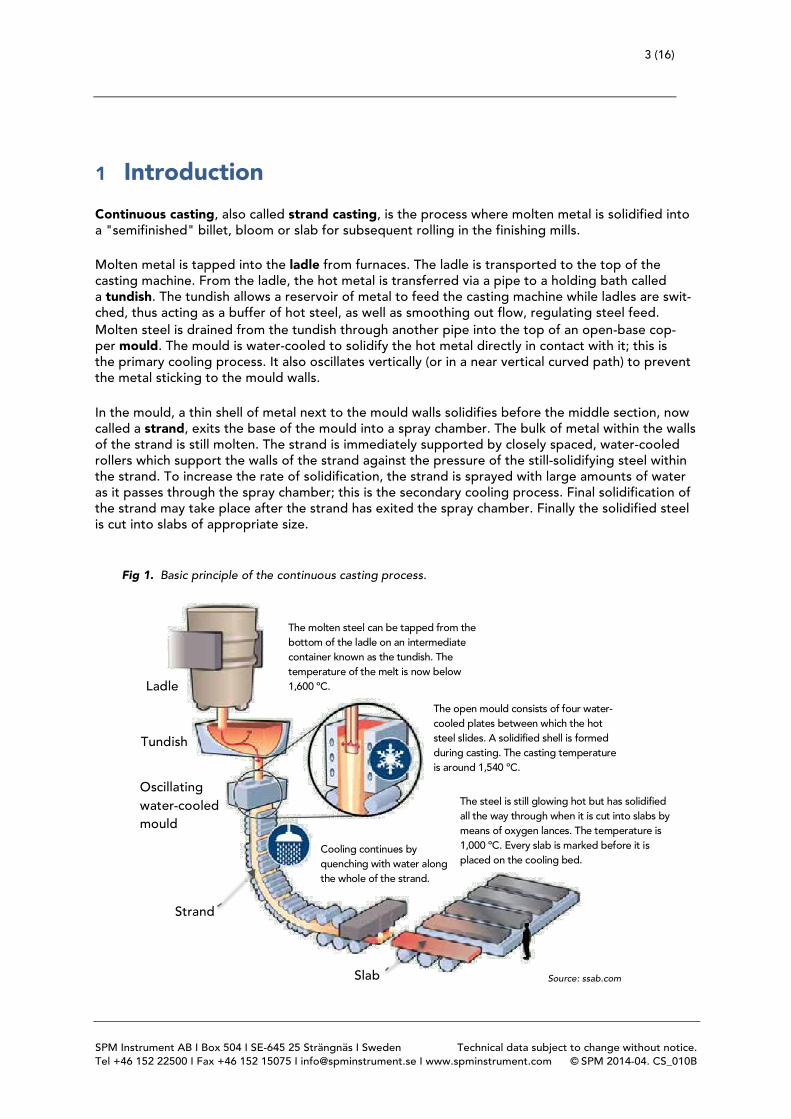
Continuous casting, also called strand casting, is the process where molten metal is solidified into a "semifinished" billet, bloom or slab for subsequent rolling in the finishing mills. Molten metal is tapped into the ladle from furnaces. The ladle is transported to the top of the casting machine. From the ladle, the hot metal is transferred via a pipe to a holding bath called a tundish. The tundish allows a reservoir of metal to feed the casting machine while ladles are swit-ched, thus acting as a buffer of hot steel, as well as smoothing out flow, regulating steel feed. Molten steel is drained from the tundish through another pipe into the top of an open-base cop-per mould. The mould is water-cooled to solidify the hot metal directly in contact with it; this is the primary cooling process. It also oscillates vertically (or in a near vertical curved path) to prevent the metal sticking to the mould walls. In the mould, a thin shell of metal next to the mould walls solidifies before the middle section, now called a strand, exits the base of the mould into a spray chamber. The bulk of metal within the walls of the strand is still molten. The strand is immediately supported by closely spaced, water-cooled rollers which support the walls of the strand against the pressure of the still-solidifying steel within the strand. To increase the rate of solidification, the strand is sprayed with large amounts of water as it passes through the spray chamber; this is the secondary cooling process. Final solidification of the strand may take place after the strand has exited the spray chamber. Finally the solidified steel is cut into slabs of appropriate size.
Fig 1. Basic principle of the continuous casting process.
The molten steel can be tapped from the bottom of the ladle on an intermediate container known as the tundish. The temperature of the melt is now below 1,600 ºC.
The open mould consists of four water-cooled plates between which the hot steel slides. A solidified shell is formed during casting. The casting temperature is around 1,540 ºC.
The steel is still glowing hot but has solidified all the way through when it is cut into slabs by means of oxygen lances. The temperature is 1,000 ºC. Every slab is marked before it is placed on the cooling bed.
Cooling continues by quenching with water along the whole of the strand.
Oscillating water-cooled mould
Strand
Slab
Tundish
Ladle
Source: ssab.com
4 (16)
SPM Instrument AB I Box 504 I SE-645 25 Strängnäs I Sweden Technical data subject to change without notice. Tel +46 152 22500 I Fax +46 152 15075 I [email protected] I www.spminstrument.com © SPM 2014-04. CS_010B
The oscillating movement of the water-cooled mould can be created in several different ways. In some equipment, the movement is created by hydraulic pistons while in other types it is created by an electrical motor connected to eccentric shafts, supported by bearings. This case study deals with condition monitoring of bearings in equipment of the latter type. This case study was done at the SSAB continuous casting plant in Luleå in northern Sweden. Over the years, SSAB has experienced numerous bearing failures in the oscillation drive system, with production losses as a consequence.
2 Conclusion and summary
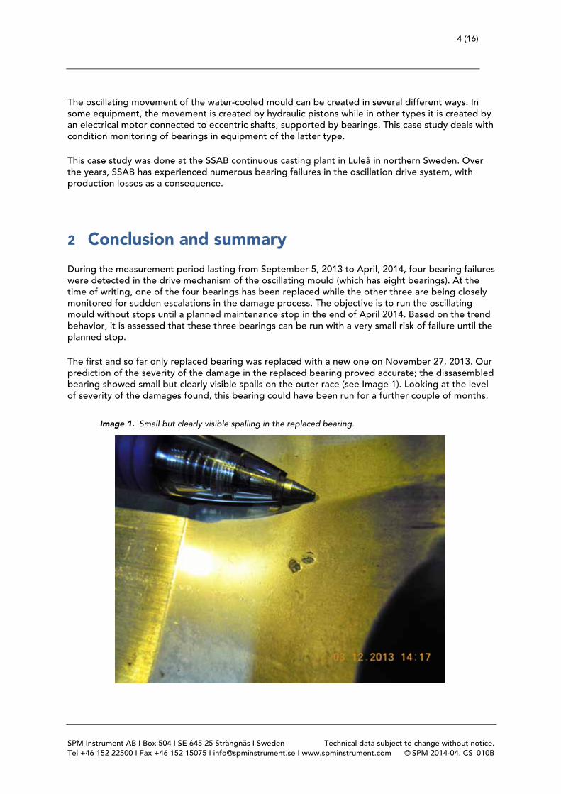
During the measurement period lasting from September 5, 2013 to April, 2014, four bearing failures were detected in the drive mechanism of the oscillating mould (which has eight bearings). At the time of writing, one of the four bearings has been replaced while the other three are being closely monitored for sudden escalations in the damage process. The objective is to run the oscillating mould without stops until a planned maintenance stop in the end of April 2014. Based on the trend behavior, it is assessed that these three bearings can be run with a very small risk of failure until the planned stop. The first and so far only replaced bearing was replaced with a new one on November 27, 2013. Our prediction of the severity of the damage in the replaced bearing proved accurate; the dissasembled bearing showed small but clearly visible spalls on the outer race (see Image 1). Looking at the level of severity of the damages found, this bearing could have been run for a further couple of months.
Image 1. Small but clearly visible spalling in the replaced bearing.
5 (16)
SPM Instrument AB I Box 504 I SE-645 25 Strängnäs I Sweden Technical data subject to change without notice. Tel +46 152 22500 I Fax +46 152 15075 I [email protected] I www.spminstrument.com © SPM 2014-04. CS_010B
3 Application description
The oscillation mould is run continuously at three distinct RPMs: 116, 121 and 126 RPM, depending on steel quality. Via a cardan shaft system, a single electric motor drives the two crank shafts which create the oscillation movement.
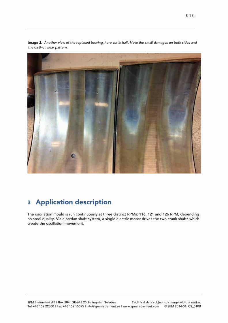
Image 2. Another view of the replaced bearing, here cut in half. Note the small damages on both sides and the distinct wear pattern.
6 (16)
SPM Instrument AB I Box 504 I SE-645 25 Strängnäs I Sweden Technical data subject to change without notice. Tel +46 152 22500 I Fax +46 152 15075 I [email protected] I www.spminstrument.com © SPM 2014-04. CS_010B
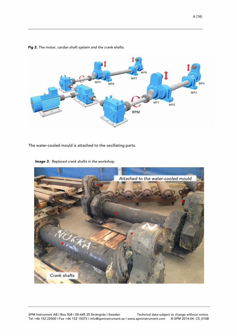
The water-cooled mould is attached to the oscillating parts.
Attached to the water-cooled mould
Crank shafts
Image 3. Replaced crank shafts in the workshop.
Fig 2. The motor, cardan shaft system and the crank shafts.
7 (16)
SPM Instrument AB I Box 504 I SE-645 25 Strängnäs I Sweden Technical data subject to change without notice. Tel +46 152 22500 I Fax +46 152 15075 I [email protected] I www.spminstrument.com © SPM 2014-04. CS_010B
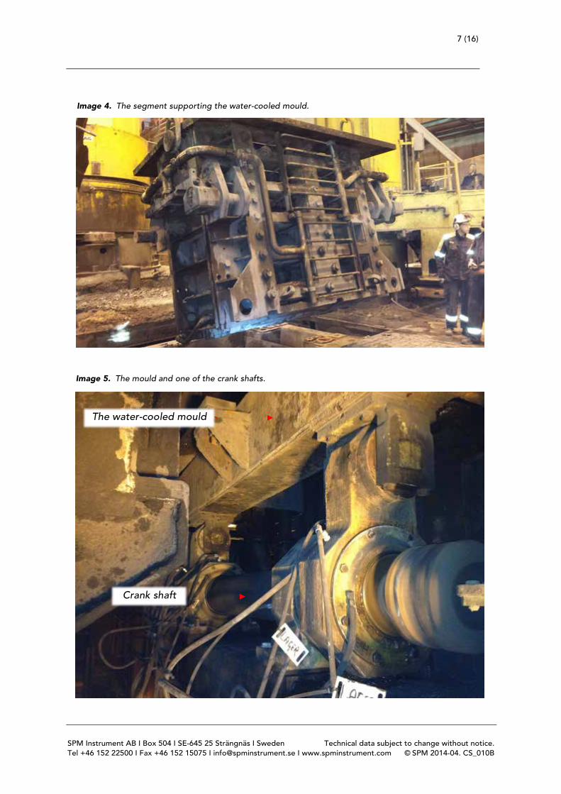
Image 4. The segment supporting the water-cooled mould.
Image 5. The mould and one of the crank shafts.
The water-cooled mould
Crank shaft

8 (16)
SPM Instrument AB I Box 504 I SE-645 25 Strängnäs I Sweden Technical data subject to change without notice. Tel +46 152 22500 I Fax +46 152 15075 I [email protected] I www.spminstrument.com © SPM 2014-04. CS_010B
The oscillating movement creates strong forces acting on the outer race, one per revolution. A po-tential outer race spall or crack is therefore expected to show up as BPFO with sidebands, with a sideband spacing of 1 X.
4 System setup
4.1 Measuring equipment
For this application, a total of eight shock pulse transducers (type 44000) is used, one on each bear-ing. The RPM is measured with one pulse per revolution via an inductive probe on one of the crank shafts. An Intellinova Compact INS18 system with a local database was considered the optimal solu-tion for this application. The customer provided VPN access to enable SPM personnel to analyze readings. The primary purpose of the measurements was to evaluate bearing condition and provide early forewarning; thus only shock pulse transducers were installed.
4.2 Condmaster setup
Each measuring point is set up identically according to the following scheme.
With this setup, the measuring time is 460.8 revolutions. With an RPM of say 116, the measuring time in seconds will be (60/116)*460.8= 238.3; close to four minutes. The measuring interval is set to one measurement per hour. Considering the history with a lot of bearing faults, high tempera-tures and heavy loads, at least four readings per day is recommended to closely monitor the condi-tion of these bearings.
Measuring point no.
No. of spectrum lines
Fmax SEF* RPM factor Rev’s (measuring time) RPM range
1 3200 100 orders 10 1 460.8 80-200
2 3200 100 orders 10 1 460.8 80-200
3 3200 100 orders 10 1 460.8 80-200
4 3200 100 orders 10 1 460.8 80-200
5 3200 100 orders 10 1 460.8 80-200
6 3200 100 orders 10 1 460.8 80-200
7 3200 100 orders 10 1 460.8 80-200
8 3200 100 orders 10 1 460.8 80-200
Table 1. Measuring point setup.
*) Symptom Enhancement Factor
9 (16)
SPM Instrument AB I Box 504 I SE-645 25 Strängnäs I Sweden Technical data subject to change without notice. Tel +46 152 22500 I Fax +46 152 15075 I [email protected] I www.spminstrument.com © SPM 2014-04. CS_010B
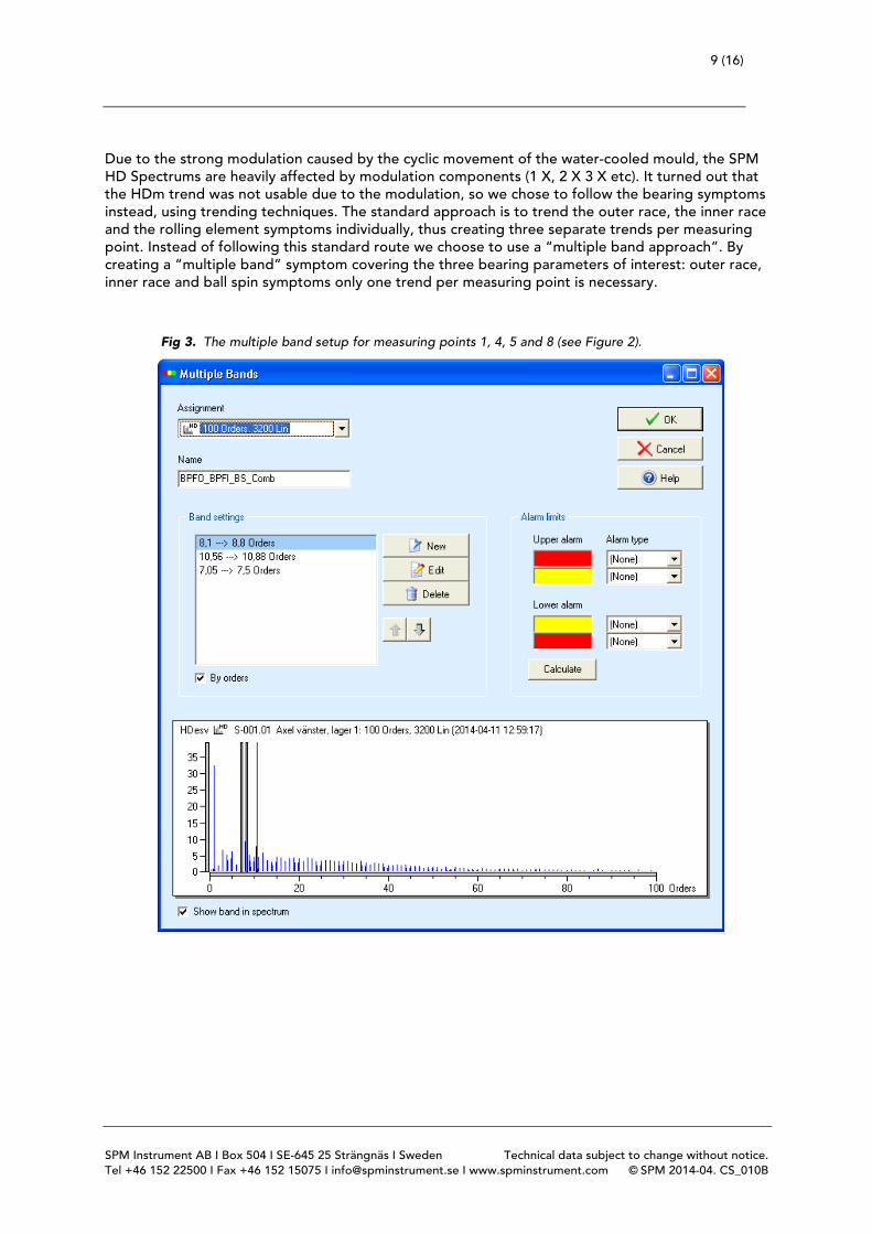
Due to the strong modulation caused by the cyclic movement of the water-cooled mould, the SPM HD Spectrums are heavily affected by modulation components (1 X, 2 X 3 X etc). It turned out that the HDm trend was not usable due to the modulation, so we chose to follow the bearing symptoms instead, using trending techniques. The standard approach is to trend the outer race, the inner race and the rolling element symptoms individually, thus creating three separate trends per measuring point. Instead of following this standard route we choose to use a “multiple band approach”. By creating a “multiple band” symptom covering the three bearing parameters of interest: outer race, inner race and ball spin symptoms only one trend per measuring point is necessary.
Fig 3. The multiple band setup for measuring points 1, 4, 5 and 8 (see Figure 2).

10 (16)
SPM Instrument AB I Box 504 I SE-645 25 Strängnäs I Sweden Technical data subject to change without notice. Tel +46 152 22500 I Fax +46 152 15075 I [email protected] I www.spminstrument.com © SPM 2014-04. CS_010B
By applying a moving average filter to the “multiple band” trends, the values are steady - regard-less of whether or not modulation is severe. Note that the “multiple band” only covers the fundamental frequencies of the bearing symptoms and no harmonic components. This is contrary to the “normal” symptoms that cover both the fun-damental frequencies and the harmonics. The reason for this more simplified setup is the fact that when a spall or crack occurs, all frequency components (fundamental frequencies and harmonics) will become stronger. In the cases described later, this behavior is very evident.
Fig 4. The multiple band setup for measuring points 2, 3, 6 and 7 (see Figure 2).
11 (16)
SPM Instrument AB I Box 504 I SE-645 25 Strängnäs I Sweden Technical data subject to change without notice. Tel +46 152 22500 I Fax +46 152 15075 I [email protected] I www.spminstrument.com © SPM 2014-04. CS_010B
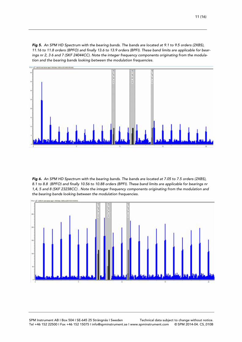
Fig 5. An SPM HD Spectrum with the bearing bands. The bands are located at 9.1 to 9.5 orders (2XBS), 11.16 to 11.8 orders (BPFO) and finally 13.6 to 13.9 orders (BPFI). These band limits are applicable for bear-ings nr 2, 3 6 and 7 (SKF 24044CC). Note the integer frequency components originating from the modula-tion and the bearing bands looking between the modulation frequencies.
Fig 6. An SPM HD Spectrum with the bearing bands. The bands are located at 7.05 to 7.5 orders (2XBS), 8.1 to 8.8 (BPFO) and finally 10.56 to 10.88 orders (BPFI). These band limits are applicable for bearings nr 1,4, 5 and 8 (SKF 23238CC) . Note the integer frequency components originating from the modulation and the bearing bands looking between the modulation frequencies.
12 (16)
SPM Instrument AB I Box 504 I SE-645 25 Strängnäs I Sweden Technical data subject to change without notice. Tel +46 152 22500 I Fax +46 152 15075 I [email protected] I www.spminstrument.com © SPM 2014-04. CS_010B
5 Case descriptions
5.1 Case #1; High values after a maintenance stop
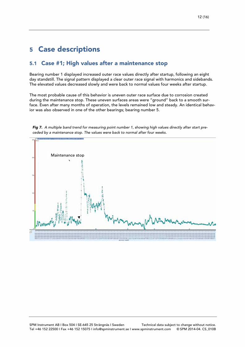
Bearing number 1 displayed increased outer race values directly after startup, following an eight day standstill. The signal pattern displayed a clear outer race signal with harmonics and sidebands. The elevated values decreased slowly and were back to normal values four weeks after startup. The most probable cause of this behavior is uneven outer race surface due to corrosion created during the maintenance stop. These uneven surfaces areas were “ground” back to a smooth sur-face. Even after many months of operation, the levels remained low and steady. An identical behav-ior was also observed in one of the other bearings; bearing number 5.
Maintenance stop
Fig 7. A multiple band trend for measuring point number 1, showing high values directly after start pre-ceded by a maintenance stop. The values were back to normal after four weeks.

13 (16)
SPM Instrument AB I Box 504 I SE-645 25 Strängnäs I Sweden Technical data subject to change without notice. Tel +46 152 22500 I Fax +46 152 15075 I [email protected] I www.spminstrument.com © SPM 2014-04. CS_010B
Fig 8. A BPFO spectrum with sidebands for measuring point 1, displaying a clear outer race damage. The measurement was taken directly after the maintenance stop.
Fig 9. Measuring point number 5; a similar behavior as in Figure 7 - high values preceded by a mainte-nance stop.
Maintenance stop
14 (16)
SPM Instrument AB I Box 504 I SE-645 25 Strängnäs I Sweden Technical data subject to change without notice. Tel +46 152 22500 I Fax +46 152 15075 I [email protected] I www.spminstrument.com © SPM 2014-04. CS_010B
5.2 Case #2; Outer race bearing damage
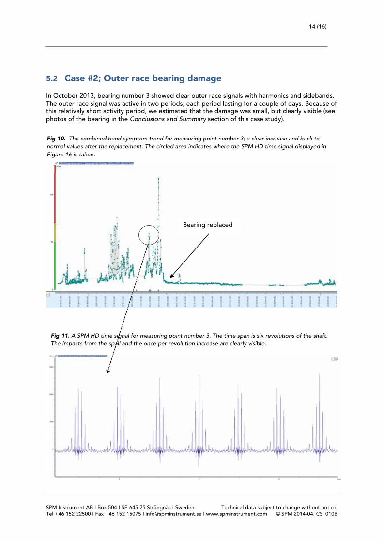
In October 2013, bearing number 3 showed clear outer race signals with harmonics and sidebands. The outer race signal was active in two periods; each period lasting for a couple of days. Because of this relatively short activity period, we estimated that the damage was small, but clearly visible (see photos of the bearing in the Conclusions and Summary section of this case study).
Fig 10. The combined band symptom trend for measuring point number 3; a clear increase and back to normal values after the replacement. The circled area indicates where the SPM HD time signal displayed in Figure 16 is taken.
Bearing replaced
Fig 11. A SPM HD time signal for measuring point number 3. The time span is six revolutions of the shaft. The impacts from the spall and the once per revolution increase are clearly visible.
15 (16)
SPM Instrument AB I Box 504 I SE-645 25 Strängnäs I Sweden Technical data subject to change without notice. Tel +46 152 22500 I Fax +46 152 15075 I [email protected] I www.spminstrument.com © SPM 2014-04. CS_010B
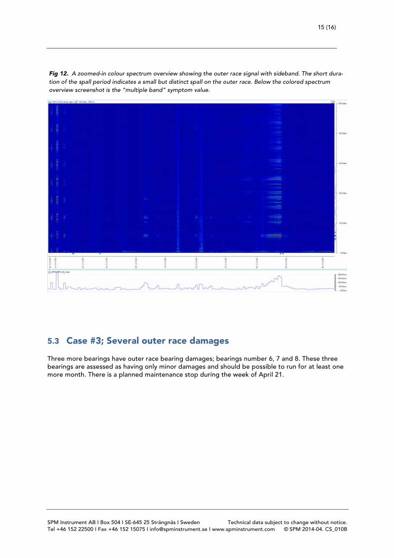
5.3 Case #3; Several outer race damages
Three more bearings have outer race bearing damages; bearings number 6, 7 and 8. These three bearings are assessed as having only minor damages and should be possible to run for at least one more month. There is a planned maintenance stop during the week of April 21.
Fig 12. A zoomed-in colour spectrum overview showing the outer race signal with sideband. The short dura-tion of the spall period indicates a small but distinct spall on the outer race. Below the colored spectrum overview screenshot is the “multiple band” symptom value.
16 (16)
SPM Instrument AB I Box 504 I SE-645 25 Strängnäs I Sweden Technical data subject to change without notice. Tel +46 152 22500 I Fax +46 152 15075 I [email protected] I www.spminstrument.com © SPM 2014-04. CS_010B
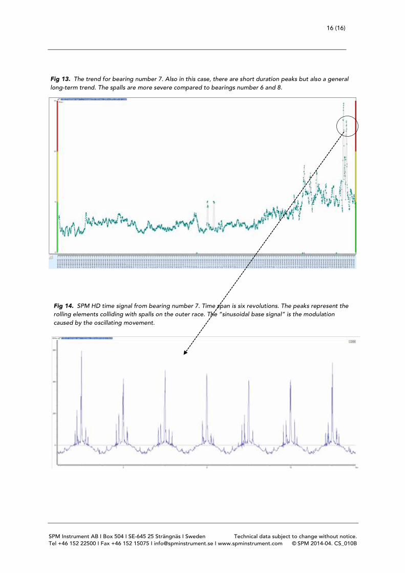
Fig 14. SPM HD time signal from bearing number 7. Time span is six revolutions. The peaks represent the rolling elements colliding with spalls on the outer race. The “sinusoidal base signal” is the modulation caused by the oscillating movement.
Fig 13. The trend for bearing number 7. Also in this case, there are short duration peaks but also a general long-term trend. The spalls are more severe compared to bearings number 6 and 8.