meso-scale computational modeling of hypervelocity impact ... · materials with meso-scale...
TRANSCRIPT

Leave footer empty – The Conference footer will be added to the first page of each paper.
MESO-SCALE COMPUTATIONAL MODELING OF
HYPERVELOCITY IMPACT DAMAGE IN ADVANCED
MATERIALS
Aleksandr Cherniaev(1), Igor Telichev(1)
(1) Department of Mechanical Engineering, University of Manitoba, E2-327 EITC, 75A Chancellors Circle, Winnipeg,
MB R3T 5V6, Canada, Email: [email protected]
ABSTRACT
Modeling of hypervelocity impact (HVI) on materials
and structures is often associated with high
computational expenses, especially when
inhomogeneous materials are involved. To reduce
computational cost, complex materials are often
represented in modeling as homogeneous substances
with the effective properties similar to those of the real
materials. Although this approach has been successfully
used in modeling of HVI on different materials with
complex architecture, there are applications where it may
not be applicable due to significant influence of
materials’ meso-scale features on resulting HVI damage.
Two of such applications are considered in this study, and
include simulation of HVI on sandwich panels with
metallic foam-cores, and composites fabricated by
filament winding. In the former case, adequate modeling
of the multi-shock action of the foam ligaments on
hypervelocity fragment cloud propagating through the
foam core requires an explicit representation of the foam
geometry in numerical model. In the latter case, the
meso-scale modeling is required due to experimentally
observed dependence of HVI damage of the composite
on the particular filament winding pattern used in its
fabrication. The study presents numerical models
developed for both of these applications and compares
numerical results with obtained experimental data.
1 INTRODUCTION
Models for the simulation of impact behavior of different
inhomogeneous materials have been described in the
literature and implemented in commercial software
packages, such as Autodyn, LS-Dyna etc. These models
are often based on the homogenization of advanced
materials with complex micro- and meso-structure, and
their representation in the modeling as a macroscopically
homogeneous media with effective properties equivalent
to those of the real materials. Although computationally
efficient, this approach may be too simplistic for some
materials with meso-scale inhomogeneities. This paper
considers two problems, where simulation of damage of
inhomogeneous materials required meso-scale
representation of the materials’ architecture. These
examples are modeling of hypervelocity impact on a
foam-core sandwich panel and simulation of HVI-
induced damage in CFRP composites fabricated by
filament winding.
Open-cell foam-core sandwich panels are considered by
many researchers as a promising alternative to
honeycomb-core panels in MMOD protection
applications. For instance, in an experimental study
presented by NASA [1], foam-core sandwich panels
(FCSPs) with 25–30% lower areal density than HCSPs
demonstrated better ballistic performance. In [2], it was
determined that, depending on impact conditions,
double-layer foam shields provided from 3 to 15%
improvement in critical projectile diameter as compared
to double-layer honeycomb shields of similar weight.
The performance improvement in case of using the foams
was not explained only as a result of the simple absence
of cells that “channel” the fragment cloud. Rather, the
radial expansion of fragment cloud and repeated impact
of fragments on individual foam cell ligaments induced
further fragmentation, melt, and vaporization of
fragments [3].
Figure 1. Open-cell aluminum foam (left) and a
fragment of a foam-core sandwich panel (right)
Material models implemented in commercial hydrocodes
and recommended for simulation of impact on foams are
represented, for example, by the LS-DYNA's *MAT_057
(*MAT_LOW_DENSITY_FOAM), *MAT_063
(*MAT_CRUSHABLE_FOAM), and a set of equations
of state for porous materials in AUTODYN (Crushable
foam EOS, Compaction EOS, P-Alpha EOS). These and
other available material models treat the foams as
homogeneous materials and, therefore, a priori unable to
represent multi-shock interactions of foam ligaments
with fragments of debris cloud propagating through the
foam.
Composite fabricated by filament winding is another
example of a material with the meso-scale
inhomogeneity. This feature results from multiple
Proc. 7th European Conference on Space Debris, Darmstadt, Germany, 18–21 April 2017, published by the ESA Space Debris Office
Ed. T. Flohrer & F. Schmitz, (http://spacedebris2017.sdo.esoc.esa.int, June 2017)

Leave footer empty – The Conference footer will be added to the first page of each paper.
interweavings of filament bands forming a filament-
wound composite part. In space, these materials can be
used in spacecraft propellant tanks (so-called composite
overwrapped pressure vessels) and remote manipulator
systems (e.g., Canadarm). Behavior of composites under
HVI has been studied experimentally and numerically by
many researchers, e.g. [4, 5]. However, most of the
reported work was confined to the standard laminated
composites and homogenization-based simulation
techniques, whereas less attention has been paid to the
filament-wound materials.
Figure 2. Filament winding
In filament winding, the carriage unit of a winding
machine moves back and forth relative to the rotating
mandrel and lays down on it the resin-impregnated fibers
(towpreg) at a specific angle. Fibers are placed onto a
mandrel in the form of filament bands, each containing
few thousands of fibers. Fig. 2 illustrates the initial stages
of filament winding. At each circuit (one back and forth
pass of the carriage unit along a mandrel), filament bands
are laid on a mandrel at “+” (forward motion) and “−”
(back motion) angle. Each circuit results in crossovers
between filament bands of “+” and “−” angle. The
presence of crossovers is intrinsic to filament winding
and forms its well recognizable patterns. The choice of a
particular winding pattern is often up to a manufacturing
engineer, as different patterns can be easily programmed
using software supplied with the filament winding
equipment (Fig. 3).
Figure 3. CFRP weaves of different winding patterns
Also, filament-wound composites contain two types of
voids: voids internal to filament bands, and voids at the
filament bands’ crossover regions (Fig. 4). Voids of the
latter type represent additional meso-scale feature of
filament-wound composites. It is believed that they may
result in stress concentration at crossovers leading to
formation of cracks and preliminary disintegration of the
filament wound composite when subjected to static or
impact loading.
Figure 4. Voids in the filament-wound composite: intra-
band voids (left) and voids at the crossovers (right)
2 MODELING OF OPEN-CELL FOAM
A mesoscale approach to the modeling of open-cell foam
geometry must be used in the HVI simulations to
represent multi-shock interactions of the foam ligaments
and hypervelocity fragment cloud propagating through
the foam. The original structure that forms metallic foam
is a three-dimensional array of bubbles having a
maximum volume for the minimal surface area and
surface energy. During the fabrication process,
membranes of the bubbles are being removed, leaving an
interconnected network of solid struts. A common
approach to geometric modeling of open-cell foams is
based on Wearie–Phelan idealization [6]. It represents a
structure consisting of equal-volume bubbles of two
different shapes: namely, the 14-sided
tetrakaidecahedron (Fig. 5a) and the 12-sided
dodecahedron (Fig. 5b). It is believed that Wearie–
Phelan packing provides a minimal surface area for a
given volume of cells/bubbles. The periodic domain
(translation unit) of the Wearie–Phelan tessellation is
shown in Fig. 5c.
Figure 5. Wearie–Phelan packing
It should be noted that the use of Wearie–Phelan
idealization suggests a regular array of bubbles; however,
real foams are random structures. To increase the realism
of the modeling, therefore, a foam randomization
mechanism is implemented. The overall algorithm for the
geometric modeling can be described as follows: 1)
generation of the representative volume element of
aluminum foam with the specified dimensions based on
Wearie–Phelan idealization [at this stage, the geometric
model consists of multiple lines connected with each
other at nodal points (see Fig. 6a)]; 2) randomization of
the foam using node perturbation (see Fig. 6b); and 3)
development of a solid geometric model using the
Leave footer empty – The Conference footer will be added to the first page of each paper.
randomized line-based geometry (see Fig. 6c).
Figure 6. Mesoscale geometric modeling of aluminum
foam: from structured frame to randomized solid model
The foam modeling algorithm has been implemented in
the form of a script written in ANSYS Parametric Design
Language. The SPH model of the foam-core sandwich
panel is depicted in Fig. 7. It consists of approximately
two million SPH particles. To represent thin ligaments of
aluminum foam with a satisfactory accuracy, a
smoothing length of 0.015mmhas been used. The model
exploited the idea of quarter-symmetry. Although
aluminum foam has a random structure and is not exactly
symmetrical relative to any cutting plane, isotropy of its
effective properties allows for such an assumption. The
foam in the model is present only in the central region of
the panel, where the most energetic fragments with the
greatest damage potential will propagate. Additional
lateral extension of the foam model was found to be
impractical, as it was associated with high computational
expenses.
Figure 7. Numerical model of the open cell foam-core
sandwich panel
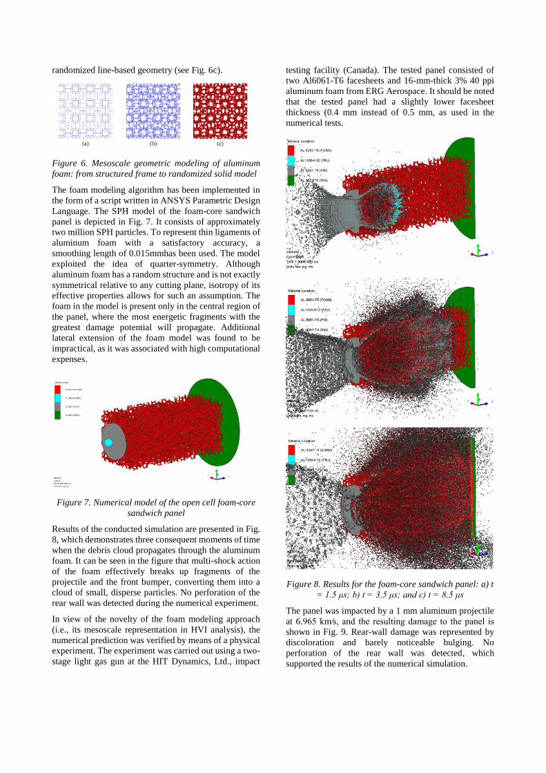
Results of the conducted simulation are presented in Fig.
8, which demonstrates three consequent moments of time
when the debris cloud propagates through the aluminum
foam. It can be seen in the figure that multi-shock action
of the foam effectively breaks up fragments of the
projectile and the front bumper, converting them into a
cloud of small, disperse particles. No perforation of the
rear wall was detected during the numerical experiment.
In view of the novelty of the foam modeling approach
(i.e., its mesoscale representation in HVI analysis), the
numerical prediction was verified by means of a physical
experiment. The experiment was carried out using a two-
stage light gas gun at the HIT Dynamics, Ltd., impact
testing facility (Canada). The tested panel consisted of
two Al6061-T6 facesheets and 16-mm-thick 3% 40 ppi
aluminum foam from ERG Aerospace. It should be noted
that the tested panel had a slightly lower facesheet
thickness (0.4 mm instead of 0.5 mm, as used in the
numerical tests.
Figure 8. Results for the foam-core sandwich panel: a) t
= 1.5 μs; b) t = 3.5 μs; and c) t = 8.5 μs
The panel was impacted by a 1 mm aluminum projectile
at 6.965 km∕s, and the resulting damage to the panel is
shown in Fig. 9. Rear-wall damage was represented by
discoloration and barely noticeable bulging. No
perforation of the rear wall was detected, which
supported the results of the numerical simulation.
Leave footer empty – The Conference footer will be added to the first page of each paper.
Figure 9. Experimental results for the foam-core
sandwich panel
Figure 10. Shapes of ejecta clouds and cone angle
measurements
Also, debris expansion angles (also referred to as “cone
angles”) were procured for both cases. For the model, this
angle could be measured directly, as shown in Fig. 10,
and this was found to be equal to 48 deg. To measure the
experimental value of this angle, it was assumed that the
debris cloud expanded within a cone, with one base
having the diameter of the perforation hole in the front
facesheet (∼3 mm) and the second base with the diameter
of the damaged region on the rear wall. As the damaged
area on the rear facesheet had a slightly elliptical shape
(possibly because of the randomness of the foam; see Fig.
10), the corresponding cone base was represented in the
calculations by a circle with the same area as the ellipse
(indicated by the dashed line in Fig. 10). With this
approximation, the debris expansion angle in the
experiment was equal to 57 deg. The observed 9 deg
difference was most likely the result of the different
facesheet thicknesses of the modeled panel (0.5 mm) and
the panel used in the experiment (0.4 mm). The model,
therefore, was deemed to provide a good approximation
of the physical phenomenon.
3 MODELING OF FILAMENT-WOUND
COMPOSITES
Numerical techniques for the modeling of composite
behavior under hypervelocity impact loading have been
described in the literature [5, 7] and implemented in
commercial software packages. These techniques are
designed for the standard laminated composites. They are
based on the homogenization of a composite laminate,
which is represented in the modeling as a
macroscopically homogeneous orthotropic media with
effective properties equivalent to those of the real
material.
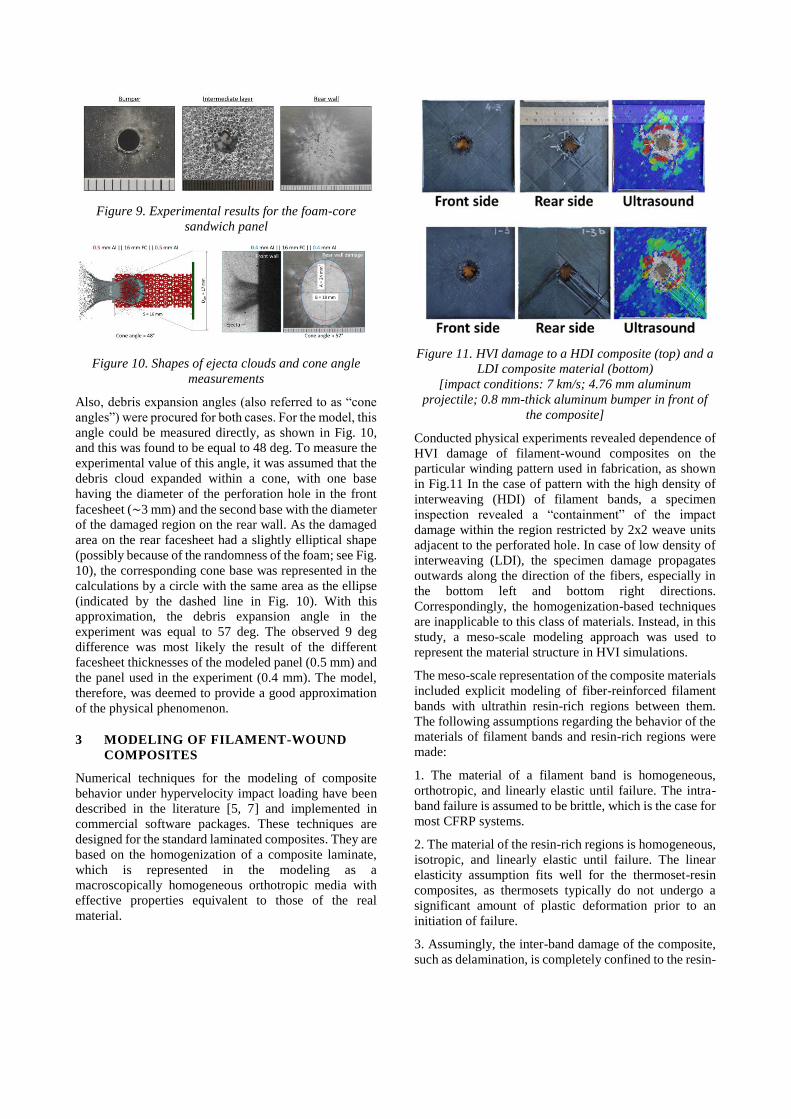
Figure 11. HVI damage to a HDI composite (top) and a
LDI composite material (bottom)
[impact conditions: 7 km/s; 4.76 mm aluminum
projectile; 0.8 mm-thick aluminum bumper in front of
the composite]
Conducted physical experiments revealed dependence of
HVI damage of filament-wound composites on the
particular winding pattern used in fabrication, as shown
in Fig.11 In the case of pattern with the high density of
interweaving (HDI) of filament bands, a specimen
inspection revealed a “containment” of the impact
damage within the region restricted by 2x2 weave units
adjacent to the perforated hole. In case of low density of
interweaving (LDI), the specimen damage propagates
outwards along the direction of the fibers, especially in
the bottom left and bottom right directions.
Correspondingly, the homogenization-based techniques
are inapplicable to this class of materials. Instead, in this
study, a meso-scale modeling approach was used to
represent the material structure in HVI simulations.
The meso-scale representation of the composite materials
included explicit modeling of fiber-reinforced filament
bands with ultrathin resin-rich regions between them.
The following assumptions regarding the behavior of the
materials of filament bands and resin-rich regions were
made:
1. The material of a filament band is homogeneous,
orthotropic, and linearly elastic until failure. The intra-
band failure is assumed to be brittle, which is the case for
most CFRP systems.
2. The material of the resin-rich regions is homogeneous,
isotropic, and linearly elastic until failure. The linear
elasticity assumption fits well for the thermoset-resin
composites, as thermosets typically do not undergo a
significant amount of plastic deformation prior to an
initiation of failure.
3. Assumingly, the inter-band damage of the composite,
such as delamination, is completely confined to the resin-

Leave footer empty – The Conference footer will be added to the first page of each paper.
rich region. The behavior in the resin-rich regions after a
failure initiation is determined by such macro-scale
parameters as fracture toughness, which allows for the
consideration of both adhesive and cohesive types of
inter-band fracture.
4. Fracture toughness of thermoset-resin composites does
not reveal strain-rate dependence, which is supported by
several investigations by previous researchers [8 - 9].
As materials of filament bands and resin rich-regions are
assumed to be linearly elastic until failure, their strength
models only require the input of elastic constants.
Pressure – volume response was modeled using nonlinear
EOS for composite filament bands, and the Gruneisen
EOS for isotropic resin-rich layers. Failure within the
filament bands and resin reach layers was modeled using
a continuum damage mechanics model available in
AUTODYN.
Figure 12. Geometrical modeling of HDI (left) and LDI
(right) composites
The modeling approach employed in this study is based
on simultaneous utilization of both SPH and FEM in each
numerical simulation. The SPH method was used to
represent the behavior of parts that exhibited
fragmentation, namely aluminum projectile projectiles
and bumpers. At the same time, composite panels with a
meso-scale representation of filament winding patterns,
which contained multiple interfaces between filament
bands and resin-rich regions, were modeled using FEM
in the Lagrangian formulation combined with the erosion
mechanism. The use of erosion helped to avoid excessive
mesh distortions and tangling at high deformations.
Figure 13. Meso-scale modeling of the filament-wound
composite
The detailed meso-scale representation of filament
winding was used only in the region of interest to
minimize the computational cost. Around that region, the
composite was represented by a homogeneous
orthotropic material with effective properties equivalent
to those of the real material. The geometrical models of
the HDI and LDI panels compared with the real
specimens are represented in Fig. 12.
HDI: superposition of all damaged surfaces
HDI: rear surface damage only
LDI: superposition of all damaged surfaces
LDI: rear surface damage only
Figure 14. Composite damage: comparison of
experimental results and numerical predictions
Fig. 13 represents the main features of the numerical
models, including: a macro-scale appearance of the
specimen model; a translational unit of the filament
winding pattern model; a pair of interweaving filament
bands; and a cross-section of a filament band with an
adjacent resin-rich region. Voids at crossover points were

Leave footer empty – The Conference footer will be added to the first page of each paper.
represented explicitly in the meso-scale model.
Fig. 14 represents comparison of experimental and
modeling results in terms of the damage to composite
panels.
A comparison of experimental results and numerical
predictions reveals the following:
• Simulations tend to somewhat underpredict the
damaged area as compared to the damage detected
by C-Scan. The exact reason for the underprediction
is unknown, but may be attributed to the presence of
a strain-rate dependence of the composite fracture
toughness that was ignored in the modeling.
• For the HDI specimen, the simulation predicts a
“containment” of the HVI damage within the region
restricted by 2x2 HDI units adjacent to the perforated
hole, which is the same damage pattern observed in
the experiment.
• For the LDI specimen, the simulation predicts
further propagation of the damage outwards along
the fiber direction, which is also consistent with the
experimental results. It should be noted, however,
that the simulation also predicts the propagation of
damage in the top-right corner of the specimen
(encircled in Fig. 14) that was not observed on the
C-Scan image.
• Damage patterns on the rear surface predicted by
simulations for both HDI and LDI specimens are
qualitatively in very good agreement with the
experiment, as shown in Fig. 14.
4 CONCLUSIONS
For the foam-core sandwich panels, the meso-scale
representation of the foam geometry is essential in HVI
simulations, as it accounts for multi-shock interactions of
the foam ligaments and hypervelocity fragment cloud
propagating through the foam. The modelling approach
considered in this study can be used in simulations
estimating ballistic limit of foam core sandwich panels
under hypervelocity impact.
Hypervelocity impact damage of a filament-wound
composite is significantly dependent on the filament
winding pattern used in its fabrication. In the presence of
the winding pattern dependence, adequate simulation of
HVI damage requires the utilization of a relatively high
level of detail in representing a filament-wound
composite. In this regard, the introduced meso-scale
modeling approach was found to be suitable for capturing
the main features of the HVI damage in the composites
with different winding patterns. This approach can be
used in the design of spacecraft filament-wound
components, in order to determine the critical level of
damage that is sustained due to orbital debris impacts.
5 REFERENCES
1. Yasensky J., Christiansen E. (2007) Hypervelocity
Impact Evaluation of Metal Foam Core Sandwich
Structures. JSC63945.
2. Ryan S., Hedman T., Christiansen E.L. (2010)
Honeycomb vs. foam: Evaluating potential upgrades
to ISS module shielding. Acta Astronautica 67, 818–
825.
3. Ryan S., Christiansen E.L. (2013) Hypervelocity
impact testing of advanced materials and structures
for micrometeoroid and orbital debris shielding.
Acta Astronautica 83, 216–231.
4. Yew C.H., Rodney B.K. (1987) A study of damage
in composite panels produced by hypervelocity
impact. Int J Impact Eng 5, 729–38.
5. Wicklein M., Ryan S., White D.M., Clegg R.A.
(2008) Hypervelocity impact on CFRP: testing,
material modelling, and numerical simulation. Int J
Impact Eng 35 (1), 1861–1869.
6. Weaire, D., and Phelan, R. (1994) A counter-
example to Kelvin’s conjecture on minimal surfaces.
Philosophical Magazine Letters 69 (2), 107–110.
7. White D.M., Tylor E.A., Clegg R.A. (2003)
Numerical simulation and experimental
characterization of direct hypervelocity impact on
spacecraft hybrid carbon fibre/Kevlar composite
structure. Int J Impact Eng 29 (1), 779–790.
8. Sun C.T., Han C. (2004) A method for testing
interlaminar dynamic fracture toughness of
polymeric composites. Compos Part B Eng 35(6–8),
647–55.
9. Tsai J.L., Guo C., Sun C.T. (2001) Dynamic
delamination fracture toughness in unidirectional
polymeric composites. Compos Sci Technol 61 (1),
87–94.

Leave footer empty – The Conference footer will be added to the first page of each paper.