meso-scale numerical modeling of the mechanical behavior ...ijetch.org/papers/641-ea0051.pdf ·...
TRANSCRIPT
Abstract—On mesoscopic level, concrete can be treated as a
three-phase composite material consisting of mortar, aggregates and interfacial transition zone (ITZ) between mortar and aggregate. A lot of research has confirmed that ITZ plays a crucial role in the mechanical fracture process of concrete. The aim of the present study is to propose a numerical method on meso-scale to analyze the failure mechanism of reinforced concrete (RC) structures under loading, and then it will help precisely predict the damage or the microcrack initiation and propagation of concrete. In this method, concrete is discretely meshed in terms of the Rigid Body Spring Model (RBSM), while the reinforcing steel bars are modeled as beam elements. The fracture process of concrete and the distribution of microcracks, as well as the load-deformation relationships are investigated and compared with the available experimental results. It is found that the numerical results are in good agreement with the experimental observations, indicating that the model can successfully simulate the fracture process of concrete and the distribution of cracks
Index Terms—Meso-scale, rigid body spring model (RBSM), reinforced concrete structure, numerical modeling
I. INTRODUCTION
From a fracture mechanical point of view, concrete is not a homogeneous material since it can be considered as a three-phase composite system consisting of aggregates embedded in a matrix of hardened cement paste, and the interfacial transition zones (ITZs) on the interface between the aggregate particles and the surrounding cement paste [1] –[4]. This description of concrete is widely recognized and usually defined as meso-scale approach, which is specifically useful when analyzing the influence of the aggregates and the ITZs on the mechanical properties of concrete, particularly on fracture behavior, as well as on the transport processes [5], [6]. Therefore, over the past few years, the numerical analysis of concrete on meso-scale has been successfully conducted, leading to a better understanding of the micro-cracking and fracture behavior of concrete. Moreover, the mesoscopic analysis can represent the effects of aggregates shape, distribution and volume fraction, particularly the thickness and properties of the ITZ [7].
Manuscript received April 15, 2013; revised June 19, 2013. This work was financially supported by the Fundamental Research Funds for the Central Universities of China (No. DUT11LK38) and the Open Research Fund Program of State key Laboratory of Hydroscience and Engineering (sklhse-2011-C-03).
L. C. Wang is with the State Key Laboratory of Coastal and Offshore Engineering, Dalian University of Technology, Dalian, 116024 China (e-mail: [email protected]).
However, the majority of the conducted studies are focused on the mechanical simulation of plain concrete due to the computational complexity and cost after including the reinforcement. The objective of this study is to develop a meso-mechanical approach to investigate the response of RC concrete structures subjected to loading. In this method, the two-dimensional (2D) meso-scale geometry of concrete is meshed by the Voronoi diagram and the discrete element method, Rigid Body Spring Model (RBSM), is adopted to perform the mechanical analysis. The advantage of the Voronoi diagram is that it can reduce mesh bias on potential crack directions because the crack initiation and propagating direction have been prescribed in advance. The continuous reinforcement is dispersed irrespective of the diagram of the concrete Voronoi meshing. Each reinforcing element is regarded as a general beam element. A specific link element with zero-size is used to simulate the bonding behavior between reinforcement and concrete. The proposed model is applied to RC samples under loading to simulate their responses and to compare with the experimental observations.
II. GENERAL DESCRIPTION OF THE BASIC MODELS
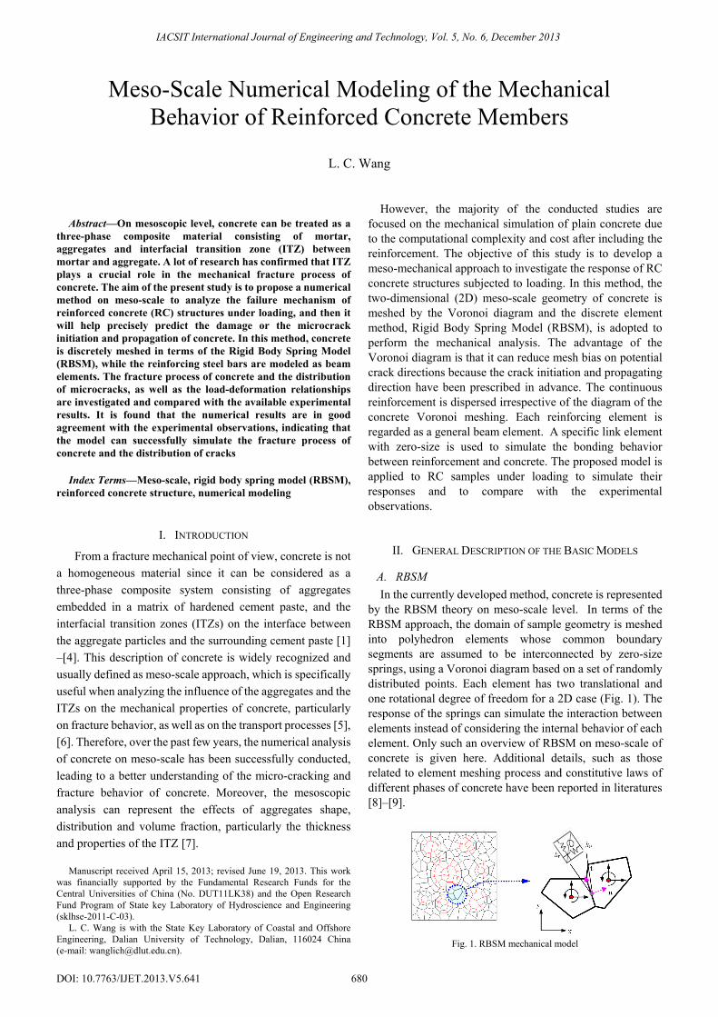
A. RBSM In the currently developed method, concrete is represented
by the RBSM theory on meso-scale level. In terms of the RBSM approach, the domain of sample geometry is meshed into polyhedron elements whose common boundary segments are assumed to be interconnected by zero-size springs, using a Voronoi diagram based on a set of randomly distributed points. Each element has two translational and one rotational degree of freedom for a 2D case (Fig. 1). The response of the springs can simulate the interaction between elements instead of considering the internal behavior of each element. Only such an overview of RBSM on meso-scale of concrete is given here. Additional details, such as those related to element meshing process and constitutive laws of different phases of concrete have been reported in literatures [8]–[9].
Fig. 1. RBSM mechanical model
Meso-Scale Numerical Modeling of the Mechanical Behavior of Reinforced Concrete Members
L. C. Wang
IACSIT International Journal of Engineering and Technology, Vol. 5, No. 6, December 2013
680DOI: 10.7763/IJET.2013.V5.641
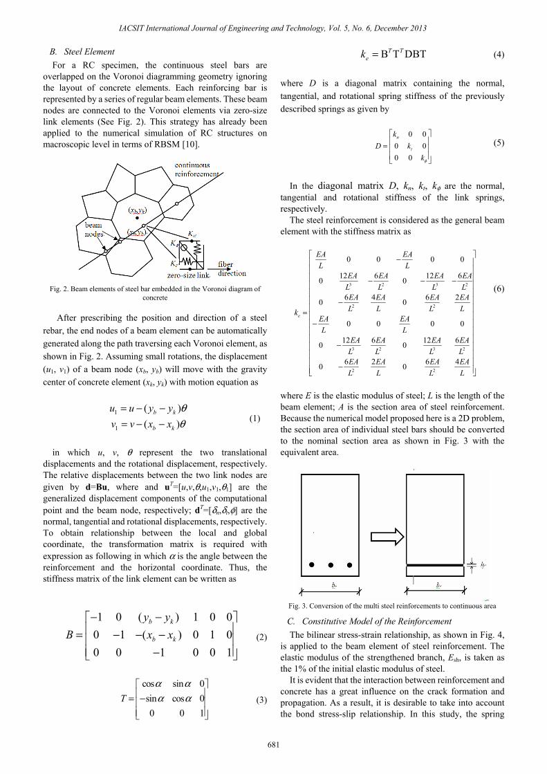
B. Steel Element For a RC specimen, the continuous steel bars are
overlapped on the Voronoi diagramming geometry ignoring the layout of concrete elements. Each reinforcing bar is represented by a series of regular beam elements. These beam nodes are connected to the Voronoi elements via zero-size link elements (See Fig. 2). This strategy has already been applied to the numerical simulation of RC structures on macroscopic level in terms of RBSM [10].
Fig. 2. Beam elements of steel bar embedded in the Voronoi diagram of
concrete
After prescribing the position and direction of a steel rebar, the end nodes of a beam element can be automatically generated along the path traversing each Voronoi element, as shown in Fig. 2. Assuming small rotations, the displacement (u1, v1) of a beam node (xb, yb) will move with the gravity center of concrete element (xk, yk) with motion equation as
1
1
( )( )
b k
b k
u u y yv v x x
θθ
= − −= − − (1)
in which u, v, θ represent the two translational
displacements and the rotational displacement, respectively. The relative displacements between the two link nodes are given by d=Bu, where and uT=[u,v,θ,u1,v1,θ1] are the generalized displacement components of the computational point and the beam node, respectively; dT=[δn,δt,φ] are the normal, tangential and rotational displacements, respectively. To obtain relationship between the local and global coordinate, the transformation matrix is required with expression as following in which α is the angle between the reinforcement and the horizontal coordinate. Thus, the stiffness matrix of the link element can be written as
1 0 ( ) 1 0 0
0 1 ( ) 0 1 00 0 1 0 0 1
b k
b k
y yB x x
− −⎡ ⎤⎢ ⎥= − − −⎢ ⎥⎢ ⎥−⎣ ⎦
(2)
cos sin 0sin cos 00 0 1
Tα αα α
⎡ ⎤⎢ ⎥= −⎢ ⎥⎢ ⎥⎣ ⎦
(3)
B T DBTT Tek = (4)
where D is a diagonal matrix containing the normal, tangential, and rotational spring stiffness of the previously described springs as given by
0 0
0 00 0
n
t
kD k
kφ
⎡ ⎤⎢ ⎥= ⎢ ⎥⎢ ⎥⎣ ⎦
(5)
In the diagonal matrix D, kn, kt, kφ are the normal,
tangential and rotational stiffness of the link springs, respectively.
The steel reinforcement is considered as the general beam element with the stiffness matrix as
3 2 3 2
2 2
3 2 3 2
2 2
0 0 0 0
12 6 12 60 0
6 4 6 20 0
0 0 0 0
12 6 12 60 0
6 2 6 40 0
e
EA EAL L
EA EA EA EAL L L LEA EA EA EAL L L Lk
EA EAL L
EA EA EA EAL L L LEA EA EA EAL L L L
⎡ ⎤−⎢ ⎥⎢ ⎥⎢ ⎥− − −⎢ ⎥⎢ ⎥⎢ ⎥−⎢ ⎥= ⎢ ⎥−⎢ ⎥⎢ ⎥⎢ ⎥
−⎢ ⎥⎢ ⎥⎢ ⎥−⎢ ⎥⎣ ⎦
(6)
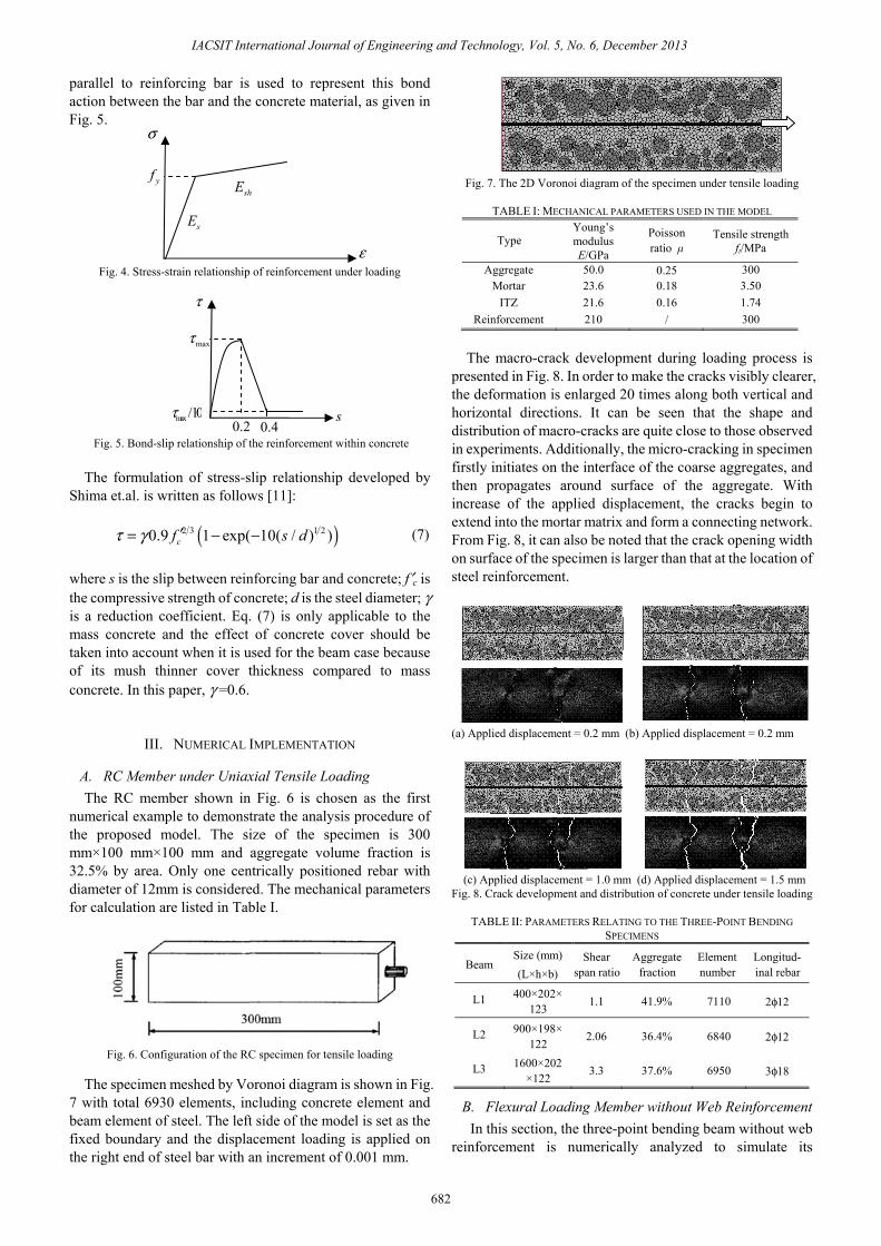
where E is the elastic modulus of steel; L is the length of the beam element; A is the section area of steel reinforcement. Because the numerical model proposed here is a 2D problem, the section area of individual steel bars should be converted to the nominal section area as shown in Fig. 3 with the equivalent area.
Fig. 3. Conversion of the multi steel reinforcements to continuous area
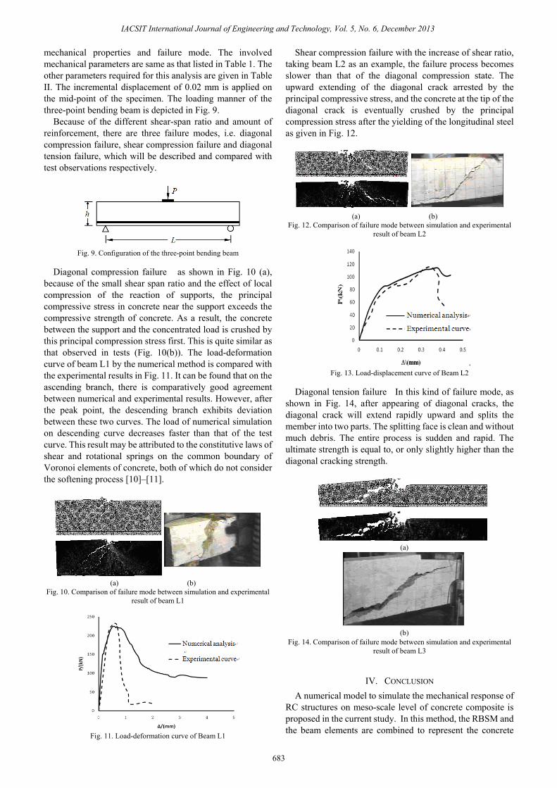
C. Constitutive Model of the Reinforcement The bilinear stress-strain relationship, as shown in Fig. 4,
is applied to the beam element of steel reinforcement. The elastic modulus of the strengthened branch, Esh, is taken as the 1% of the initial elastic modulus of steel.
It is evident that the interaction between reinforcement and concrete has a great influence on the crack formation and propagation. As a result, it is desirable to take into account the bond stress-slip relationship. In this study, the spring
IACSIT International Journal of Engineering and Technology, Vol. 5, No. 6, December 2013
681
parallel to reinforcing bar is used to represent this bond action between the bar and the concrete material, as given in Fig. 5.
Fig. 4. Stress-strain relationship of reinforcement under loading
Fig. 5. Bond-slip relationship of the reinforcement within concrete
The formulation of stress-slip relationship developed by
Shima et.al. is written as follows [11]:
( )2 3 1 20.9 1 exp( 10( / ) )cf s dτ γ ′= − − (7)
where s is the slip between reinforcing bar and concrete; f′c is the compressive strength of concrete; d is the steel diameter; γ is a reduction coefficient. Eq. (7) is only applicable to the mass concrete and the effect of concrete cover should be taken into account when it is used for the beam case because of its mush thinner cover thickness compared to mass concrete. In this paper, γ =0.6.
III. NUMERICAL IMPLEMENTATION
A. RC Member under Uniaxial Tensile Loading The RC member shown in Fig. 6 is chosen as the first
numerical example to demonstrate the analysis procedure of the proposed model. The size of the specimen is 300 mm×100 mm×100 mm and aggregate volume fraction is 32.5% by area. Only one centrically positioned rebar with diameter of 12mm is considered. The mechanical parameters for calculation are listed in Table I.
Fig. 6. Configuration of the RC specimen for tensile loading
The specimen meshed by Voronoi diagram is shown in Fig.
7 with total 6930 elements, including concrete element and beam element of steel. The left side of the model is set as the fixed boundary and the displacement loading is applied on the right end of steel bar with an increment of 0.001 mm.
Fig. 7. The 2D Voronoi diagram of the specimen under tensile loading
TABLE I: MECHANICAL PARAMETERS USED IN THE MODEL
Type Young’s modulus E/GPa
Poisson ratio μ
Tensile strengthft/MPa
Aggregate 50.0 0.25 300 Mortar 23.6 0.18 3.50
ITZ 21.6 0.16 1.74 Reinforcement 210 / 300
The macro-crack development during loading process is
presented in Fig. 8. In order to make the cracks visibly clearer, the deformation is enlarged 20 times along both vertical and horizontal directions. It can be seen that the shape and distribution of macro-cracks are quite close to those observed in experiments. Additionally, the micro-cracking in specimen firstly initiates on the interface of the coarse aggregates, and then propagates around surface of the aggregate. With increase of the applied displacement, the cracks begin to extend into the mortar matrix and form a connecting network. From Fig. 8, it can also be noted that the crack opening width on surface of the specimen is larger than that at the location of steel reinforcement.
(a) Applied displacement = 0.2 mm (b) Applied displacement = 0.2 mm
(c) Applied displacement = 1.0 mm (d) Applied displacement = 1.5 mm
Fig. 8. Crack development and distribution of concrete under tensile loading
TABLE II: PARAMETERS RELATING TO THE THREE-POINT BENDING SPECIMENS
Beam Size (mm)(L×h×b)
Shear span ratio
Aggregate fraction
Element number
Longitud-inal rebar
L1 400×202×123 1.1 41.9% 7110 2φ12
L2 900×198×122 2.06 36.4% 6840 2φ12
L3 1600×202×122 3.3 37.6% 6950 3φ18
B. Flexural Loading Member without Web Reinforcement In this section, the three-point bending beam without web reinforcement is numerically analyzed to simulate its
yf
sE
shE
σ
ε
maxτ
0.2 0.4
τ
smax /10τ
IACSIT International Journal of Engineering and Technology, Vol. 5, No. 6, December 2013
682
mechanical properties and failure mode. The involved mechanical parameters are same as that listed in Table 1. The other parameters required for this analysis are given in Table II. The incremental displacement of 0.02 mm is applied on the mid-point of the specimen. The loading manner of the three-point bending beam is depicted in Fig. 9.
Because of the different shear-span ratio and amount of reinforcement, there are three failure modes, i.e. diagonal compression failure, shear compression failure and diagonal tension failure, which will be described and compared with test observations respectively.
Fig. 9. Configuration of the three-point bending beam
Diagonal compression failure as shown in Fig. 10 (a),
because of the small shear span ratio and the effect of local compression of the reaction of supports, the principal compressive stress in concrete near the support exceeds the compressive strength of concrete. As a result, the concrete between the support and the concentrated load is crushed by this principal compression stress first. This is quite similar as that observed in tests (Fig. 10(b)). The load-deformation curve of beam L1 by the numerical method is compared with the experimental results in Fig. 11. It can be found that on the ascending branch, there is comparatively good agreement between numerical and experimental results. However, after the peak point, the descending branch exhibits deviation between these two curves. The load of numerical simulation on descending curve decreases faster than that of the test curve. This result may be attributed to the constitutive laws of shear and rotational springs on the common boundary of Voronoi elements of concrete, both of which do not consider the softening process [10]–[11].
(a) (b)
Fig. 10. Comparison of failure mode between simulation and experimental result of beam L1
Fig. 11. Load-deformation curve of Beam L1
Shear compression failure with the increase of shear ratio, taking beam L2 as an example, the failure process becomes slower than that of the diagonal compression state. The upward extending of the diagonal crack arrested by the principal compressive stress, and the concrete at the tip of the diagonal crack is eventually crushed by the principal compression stress after the yielding of the longitudinal steel as given in Fig. 12.
(a) (b)
Fig. 12. Comparison of failure mode between simulation and experimental result of beam L2
Fig. 13. Load-displacement curve of Beam L2
Diagonal tension failure In this kind of failure mode, as
shown in Fig. 14, after appearing of diagonal cracks, the diagonal crack will extend rapidly upward and splits the member into two parts. The splitting face is clean and without much debris. The entire process is sudden and rapid. The ultimate strength is equal to, or only slightly higher than the diagonal cracking strength.
(a)
(b)
Fig. 14. Comparison of failure mode between simulation and experimental result of beam L3
IV. CONCLUSION A numerical model to simulate the mechanical response of
RC structures on meso-scale level of concrete composite is proposed in the current study. In this method, the RBSM and the beam elements are combined to represent the concrete
IACSIT International Journal of Engineering and Technology, Vol. 5, No. 6, December 2013
683
composite material and the steel reinforcement respectively. In addition, one kind of zero-size link element is adopted to simulate the bond slip relationship between concrete and steel bars.
By simulating the failure process of RC members under tensile and bending load, the following conclusions can be drawn: 1) On meso-scale, concrete is considered as composing of
coarse aggregate, mortar and the interfacial transition zone between the aggregates and mortar in terms of the mechanical properties of each phase and the cracking potential among these components. The method of including reinforcement into concrete model is practical to describe the role of strengthening effect of steel bars and the interaction between concrete and steel.
2) The model can successfully simulate the fracture process of concrete and the distribution of cracks, as well as the load-deformation relationships. It is shown that the numerical results are in good agreement with the experimental observations in terms of the failure mode and the load-deformation curves.
REFERENCES [1] B. H. Oh and S. Y. Jang, “Prediction of diffusivity of concrete based on
simple analytic equations,” Cement and Concrete Research, vol. 34, no. 3, pp. 463-480, 2004.
[2] S. Caré and E. Hervé, “Application of an n-phase model of the diffusion coefficient of chloride in mortar,” Transport in Porous Media, vol. 56, no. 2, pp. 119-135, 2004.
[3] H. Sadouki and J. G. M. V. Mier, “Meso-level analysis of moisture flow in cement composites using a lattice-type approach,” Materials and Structures, vol. 30, no. 10, pp. 579-587, 1997.
[4] X. Q. Zhou and H. Hao, “Mesoscale modelling of concrete tensile failure mechanism at high strain rates,” Computers and Structures, vol. 86, no. 21-22, pp. 2013-2026, 2008.
[5] G. V. Guinea, K. E. Sayed, C. G. Rocco, M. Elices, and J. Planas, “The effect of the bond between the matrix and the aggregates on the cracking mechanism and fracture parameters of concrete,” Cement and Concrete Research, vol. 32, no. 12, pp. 1961-1970, 2002.
[6] L. C. Wang and T. Ueda, “Mesoscale modeling of water penetration into concrete by capillary absorption,” Ocean Engineering, vol. 38, no. 4, pp. 519-528, 2011.
[7] S. M. Kim, and R. K. A. A. Rub, “Meso-scale computational modeling of the plastic-damage response of cementitious composites,” Cement and Concrete Research, vol. 41, no. 3, pp. 339-358, 2011.
[8] K. Nagai, Y. Sato and T. Ueda, “Mesoscopic simulation of failure of mortar and concrete by 2D RBSM,” Journal of Advanced Concrete Technology, vol. 2, no. 3, pp. 359-374, 2004.
[9] Z. L. Wang, F. Lin and X. L. Gu, “Numerical simulation of failure process of concrete under compression based on meso-scale discrete element model,” Tsinghua Science and Technology, vol. 13, no. S1, pp. 19-25, 2008.
[10] J. E. Bolander and S. Saito, “Fracture analyses using spring networks with random geometry,” Engineering and Fracture Mechanics, vol. 61, no. 5-6, pp, 569-591, 1998.
[11] H. Shima, L. Chou and H. Okamura, “Bond-slip-strain relationship of deformed bars embedded in massive concrete,” Concrete Library, JSCE, no. 10, pp. 79-94, 1987.
L. C. Wang was born in Shandong Province, China in Jan. 1975. He studied at Dalian University of Technology of China from 1997 to 2002, where he received his PhD in 2002 in the field of structural engineering.
From August 2006 to March 2008, he worked as a Postdoctoral Researcher in Hokkaido University of Japan. Currently, he is working as an Associate Professor majoring in Structure Engineering at Dalian University
of Technology. He has written and co-authored many papers, mainly on concrete durability, damage mechanism and numerical simulation of aggressive mass transport in concrete. He also lectured his research achievements in some international conferences. Three of them are listed as: [1] “Mesoscale modeling of water penetration into concrete by capillary absorption,” Ocean Engineering, vol. 38, no. 4, pp. 519-528, 2011. [2] “Mesoscale modelling of the chloride diffusion in cracks and cracked concrete,” Journal of Advanced Concrete Technology, vol. 9, no. 3, pp. 241-249, 2011. [3] “Mesoscale simulation of chloride diffusion in concrete considering binding capacity and concentration dependence,” Computers and Concretes., vol. 8, no. 2, pp. 125-142, 2011
Dr. Wang is a member of China Association for Engineering Construction Standardization. He is also a member of the revision committee of the national standard of China “Code for Design of Chimneys”.
IACSIT International Journal of Engineering and Technology, Vol. 5, No. 6, December 2013
684