mesh network for rfid and electric vehicle monitoring in...
TRANSCRIPT
Accepted to Journal of Communication Software and Systems Vol.10. No.2 June, 2014
Manuscript received March 15, 2014; revised June 4, 2014.
This work has been supported by LADWP/DOE fund 20699 & 20686, (Smart Grid Regional Demonstration Project), U.S.A. Authors
are with Department of Mechanical and Aerospace Engineering, University of California, Los Angeles, U.S.A. E-mails: chingyenchung,
ashepelev, peterchu, [email protected], and [email protected]
Mesh Network for RFID and Electric Vehicle
Monitoring in Smart Charging Infrastructure
Ching-Yen Chung, Aleksey Shepelev, Charlie Qiu, Chi-Cheng Chu, and Rajit Gadh
Abstract: With an increased number of plug-in electric vehicles (PEVs) on the roads, PEV charging infrastructure is gaining an ever-
more important role in simultaneously meeting the needs of drivers and those of the local distribution grid. However, the current
approach to charging is not well suited to scaling with the PEV market. If PEV adoption continues, charging infrastructure will have
to overcome its current shortcomings such as unresponsiveness to grid constraints, low degree of autonomy, and high cost, in order to
provide a seamless and configurable interface from the vehicle to the power grid. Among the tasks a charging station will have to
accomplish will be PEV identification, charging authorization, dynamic monitoring, and charge control. These will have to be done
with a minimum of involvement at a maximum of convenience for a user. The system proposed in this work allows charging stations to
become more responsive to grid constraints and gain a degree of networked autonomy by automatically identifying and authorizing
vehicles, along with monitoring and controlling all charging activities via an RFID mesh network consisting of charging stations and
in-vehicle devices. The proposed system uses a ZigBee mesh network of in-vehicle monitoring devices which simultaneously serve as
active RFID tags and remote sensors. The system outlined lays the groundwork for intelligent charge-scheduling by providing access
to vehicle’s State of Charge (SOC) data as well as vehicle/driver IDs, allowing a custom charging schedule to be generated for a
particular driver and PEV. The approach presented would allow PEV charging to be conducted effectively while observing grid
constraints and meeting the needs of PEV drivers.
Index terms: Electrical vehicle charging, power distribution control, smart grids, RFID, Wireless LAN, wireless mesh network,
Zigbee, state of charge, V2G
I. INTRODUCTION
As the number of Plug-in Electric Vehicles (PEVs) on the roads increases, charging stations in both parking structures and
private garages will become more prevalent. To meet the future needs of PEV stakeholders such as drivers, distribution grid
operators, electric utilities and others, the charging infrastructure will need to evolve into a more grid-responsive, dynamic,
intelligent, and convenient system.
Several problems exist with today’s approach to charging PEVs. Primary among these is the fact that the current laissez
faire system is not responsive to grid limitations and therefore not well suited for large-scale use. PEVs represent non-negligent
electrical loads of up to 6 kW [1], and their continued treatment as conventional loads will present problems for the power grid
with further market adoption of PEVs. It has been presented that voltage fluctuations and increased on-peak load caused by
uncoordinated charging activities will lead to higher blackout probability [2], among other problems. To make matters worse, no
charging station is currently capable of performing demand-response on request from a utility or distribution system operator.
In addition to the aforementioned problem, the current approach to PEV charging lacks technical sophistication and user-
convenience, which will impede market adoption if left unaddressed. Even the most sophisticated charging stations must be
manually pre-programmed to perform scheduled charging, require user input to authenticate charging or accept a payment. No
station is currently capable of computing a vehicle-specific charging schedule that takes the PEV’s state of charge (SOC) into
account. This is largely due to the fact that no standard exists to regulate the information exchange between PEVs and Electric
Vehicle Support Equipment (EVSE) during the charging process. The current SAE J1772 standard [3] does not allow Vehicle
ID or battery charge information to be communicated, but instead only communicates power availability and the ability of a
PEV to accept power. Consequently, the attributes of PEVs are not available to outside third parties, including the EVSE. There
are few ways to establish Vehicle to Grid (V2G) communication without substantial modifications to the vehicles, the charging
interface and the charging stations currently on the market. Before V2G communications standards such as SAE J2836/1-6 and
J2847/1-5 [4] are adopted, however, custom communication channels must be implemented in order to obtain a vehicle ID or
battery state of charge (SOC) from a PEV.
In addition to the inability to receive charge information from a PEV, current charging stations are unable to remotely
recognize incoming client vehicle and authorize charging without additional user interaction.
The UCLA Smart-Grid Energy Research Center (SMERC) has been developing the WINSmartEVTM
[5-8] research
platform to solve the inherent problems with the current approach to PEV charging. In order to address the inability of current
systems to respond to grid-imposed constraints, WINSmartEVTM
consists of a centrally controlled network of charging stations.
The system’s charging controller is able to schedule charging on each of the charging stations under its control and switch
between multiple PEVs at a single charging station. To address the lack of technical sophistication and resulting inconvenience
for the user of existing charging stations, the WINSmartEVTM
system currently allows user authentication, billing and record-
keeping to be performed through a smart-phone interface.

Accepted to Journal of Communication Software and Systems Vol.10. No.2 June, 2014
The current WINSmartEVTM
infrastructure is the first step in achieving a grid-responsive, intelligent, and convenient
charging system. The improvements presented in this paper represent the next step forward. In order to allow the
WINSmartEVTM
charging controller to derive a vehicle-specific charging schedule that takes both the vehicle’s SOC, driver
preferences, and the grid load into account, we propose a solution for remotely monitoring the SOC throughout the charging
process by using in-vehicle monitoring devices called Vehicle Monitoring/Identification Modules (VMMs).
In order to simplify user interactions and make charging more convenient, we propose a solution for remotely
authenticating and authorizing vehicles for charging using the same VMM devices. Unlike traditional point of sale (POS)
devices used in un-networked charging stations or short range RFID cards used in networked stations [9-10], no extra
authorization step is required on the part of the user. No passive RFID tags or readers are used in the proposed solution.
Communicating through a ZigBee mesh network, VMMs serve the purpose of active RFID tags for vehicle identification and
charging authorization. These devices allow charging authorization to take place seamlessly at multiple charging stations within
wireless signal range. The VMMs communicate directly with the control center through a ZigBee mesh network, thus
simplifying the system and eliminating the need for layered architecture to manage a variety of automatic identification
hardware [11].
This paper is structured in the order outlined below. First, the design of the existing WINSmartEVTM
system is presented in
detail. Afterwards, each of the proposed updates including remote charge-monitoring and remote charging authorization is
described in detail. Finally, results of the implementation and experimental results of system function and performance are
presented and discussed.
II. EXISTING WINSMARTEVTM
SYSTEM
WINSmartEVTM
is a centrally controlled and networked charging system that allows up to four PEVs to be charged at a
single charging station at any one time, as shown in Fig. 1. Each of the four PEVs at a single station may be charged at a unique
power level. This system takes the first step towards grid-responsive and vehicle-specific charging control by allowing a
charging controller to monitor and regulate all charging stations on its network.
Figure 1. Four-channel smart charging station with EVs
In addition to networked charging control and variable-current multiplexed charging, WINSmartEVTM
adds a host of
features aimed at increasing user-friendliness and convenience. The system employs a mobile app that allows an authorized user
to check a list of available charging stations, remotely start or stop PEV charging, check charging status, view monthly charging
records, and manage his/her account via a mobile device. Fig 2 shows the mobile interface.
Figure 2. WINSmartEVTM Mobile app
The WINSmartEVTM
system hardware consists of a server-based aggregate control center, communication network and
multiple smart-charging stations. The architecture is illustrated in Fig. 3.

Accepted to Journal of Communication Software and Systems Vol.10. No.2 June, 2014
Figure 3. WINSmartEVTM Architecture
A. Aggregate charging controller
The server-based aggregate charging control system consists of a station and vehicle database, station controller, a system
administrator’s control interface, and a user control interface. The database contains data about all charging stations and electric
vehicles on the WINSmartEVTM
network. The station controller initiates and terminates charging activities based on vehicle
availability and user or administrator commands. The administrator’s control interface, shown in Fig. 4, allows individual
stations to be monitored and manually controlled by a system administrator. The user control interface allows a user to control
charging of their PEV through the mobile interface shown in Fig. 2.
Figure 4. Screenshot of Monitoring and Control Center
B. Communication network
The charging controller communicates with all WINSmartEVTM
charging stations through a network consisting of wireless
and wired connections. Ethernet is used where a wired connection is practical. In more remote locations, 3G wireless
communication is used. If multiple charging stations are located within close signal range, a ZigBee wireless network is
established between them and a single station acts as a communication link with the central controller. In certain cases, Power-
Line Communication (PLC) is used to establish communication between stations located too far for a ZigBee network and away
from any available Ethernet ports.
C. Charging stations
The charging stations consist of a 3G wireless gateway, a control unit, and current meters with controllable relays as shown
in Fig. 5. ZigBee is used for communication between the gateway, the control unit and the current meters. If multiple stations
are within close geographic proximity, only one station is equipped with a 3G gateway. The rest receive controller commands
relayed through the 3G-equipped station.

Accepted to Journal of Communication Software and Systems Vol.10. No.2 June, 2014
Figure 5. Details of smart charging station
III. PROPOSED SYSTEM
While the current WINSmartEVTM
system builds a strong foundation for a networked charging system that is intelligent,
flexible and responsive to grid limitations, there are tangible opportunities for further development. For example, the existing
system does not account for a PEV’s instantaneous state of charge or its driver’s typical driving cycle when scheduling charging,
leading to less-than-optimal scheduling. Furthermore, opportunities exist to further improve user convenience by limiting the
number of steps the user has to complete before charging their vehicle.
The proposed system addresses many shortcomings of the existing WINSmartEVTM
architecture by implementing the pre-
requisite hardware what will allow the charging controller to prioritize PEV charging according to an individual vehicle’s charge
state and a driver’s typical commute. In addition, the new system allows arriving vehicles to be identified and authorized for
charging without any actions on the part of the user. These improvements allow the WINSmartEVTM
system to gain a level of
sophistication that allows it to become more responsive to the needs of the grid while meeting the convenience needs of PEV
drivers. In addition, these new capabilities have been achieved with few changes in system architecture, require minimal
additional investment and do not involve any modifications to a PEV’s factory charging interface.
The new charge monitoring and control capability as well as the remote authentication capability is achieved with three
additional hardware components: an in-Vehicle Monitoring/Identification Module (VMM) [14], a ZigBee wireless network
coordinator and a pilot-signal monitor located in each charging station for PEV plug-in detection.
Vehicle Monitoring/Identification Modules (VMM) act as RFID tags [13] for vehicle or driver identification, charging
authorization, and charge monitoring. These devices allow charging authorization to take place seamlessly at multiple charging
stations within wireless signal range and transmit the state of charge and other PEV information on request from a controller.
The ZigBee wireless network coordinator allows multiple vehicles and charging stations to establish a wireless network and
communicate with the server-based charging controller. The coordinator establishes a ZigBee network and relays messages from
the control center to each charging station belonging to the local ZigBee network.
PEV pilot-signal monitor is located in each charging station and monitors the pilot signal voltage in order to detect the
presence and status of the PEV at the given station.
A. Vehicle Monitoring/Identification Module (VMM)
The VMM has the capability of monitoring the state of the PEV through the vehicle’s CAN bus and uniquely identifying
each PEV by its 64-bit ZigBee MAC address. The module is consequently an active RFID tag and a remote sensor with the
ability to provide SOC, battery voltage, battery temperature and other information. The schematic and a cutaway view of the
VMM are shown in Fig. 6.

Accepted to Journal of Communication Software and Systems Vol.10. No.2 June, 2014
Figure 6. Schematic and cutaway view of VMM [13]
For communication on the mesh network, the device employs a Texas Instrument ZigBee board equipped with an MSP430
microcontroller and a CC2530 RF transceiver. These devices are configured to act as a ZigBee router. The device uses an
MCP2551 CAN transceiver and an ATMega328P microprocessor to monitor the PEV’s CAN bus. The firmware flow of
MSP430 is shown in Fig. 7.
Figure 7. ZigBee firmware flow in the VMM [14]
The firmware on the MSP430 is responsible for many tasks including establishing a connection with the ZigBee
coordinator, responding to ID and data requests, and maintaining the connection through a periodic handshake. The timer
interrupt logic in the lower right corner of Fig. 7 is used to ensure connectivity with the coordinator. The interrupt keeps a
running time count and sets flags that are used in the main loop to issue handshake massage. The firmware restarts the node if no
response is received to the handshake in an attempt to re-establish a lost connection.
Fig. 8 shows the ATMega328P firmware logic flowchart of the VMM. This microcontroller is the interface between the
MCP2551 CAN Transceiver and the ZigBee router.

Accepted to Journal of Communication Software and Systems Vol.10. No.2 June, 2014
Start
Received SOC request?
Decode message, send SOC to ZigBee
node
Message contains SOC?
Received CAN message?
Timeout?
Begin main loop
Initialize Atmega328 and
MCP2551
NY N
Y
N
Y
Figure 8. VMM microcontroller ATMega328P firmware flow [14]
Whenever a command to retrieve data is received from the MSP430, the program on ATMega328P listens for the correct
message on the CAN bus, decodes it, and transmits the information back to the MSP430. The MSP430 then transmits the data
on the ZigBee network to the coordinator node.
In addition to the ability of the VMM to monitor vehicle states, it may be used as a supplemental solution to detect faults in
the EVSE. Integrated power consumption data from the EVSE may be compared to the incremental SOC change of the PEV.
Significant differences in readings would indicate faults in the current-metering circuit.
B. RFID Reader: ZigBee Coordinator
The ZigBee coordinator, located in the master EVSE, serves as the RFID reader, sets up the ZigBee network and handles
messages between the gateway and the end devices/routers. When a ZigBee end device/router joins the mesh network, the
coordinator assigns it a 16 bits dynamic address and associates the dynamic address with the unique MAC address of the ZigBee
device. These identifiers are used to correctly route messages as well as for PEV charge authorization. The coordinator
implementation consists of a TI CC2530ZNP, a MAX3232 level shifter for serial I/O, and a voltage regulator, as shown in Fig.
9.
Figure 9. ZigBee coordinator implementation [13]
In order to ensure a stable connection with each ZigBee device on the network, a handshake protocol has been
implemented between the coordinator and routers, as summarized in Table I.
TABLE I. ZIGBEE HANDSHAKE COMMANDS
Command Initiating
Device
Format
Request ZigBee
router
“comdtest[MAC address]”
Accepted to Journal of Communication Software and Systems Vol.10. No.2 June, 2014
Response ZigBee
coordinator
“comdresp[MAC address]”
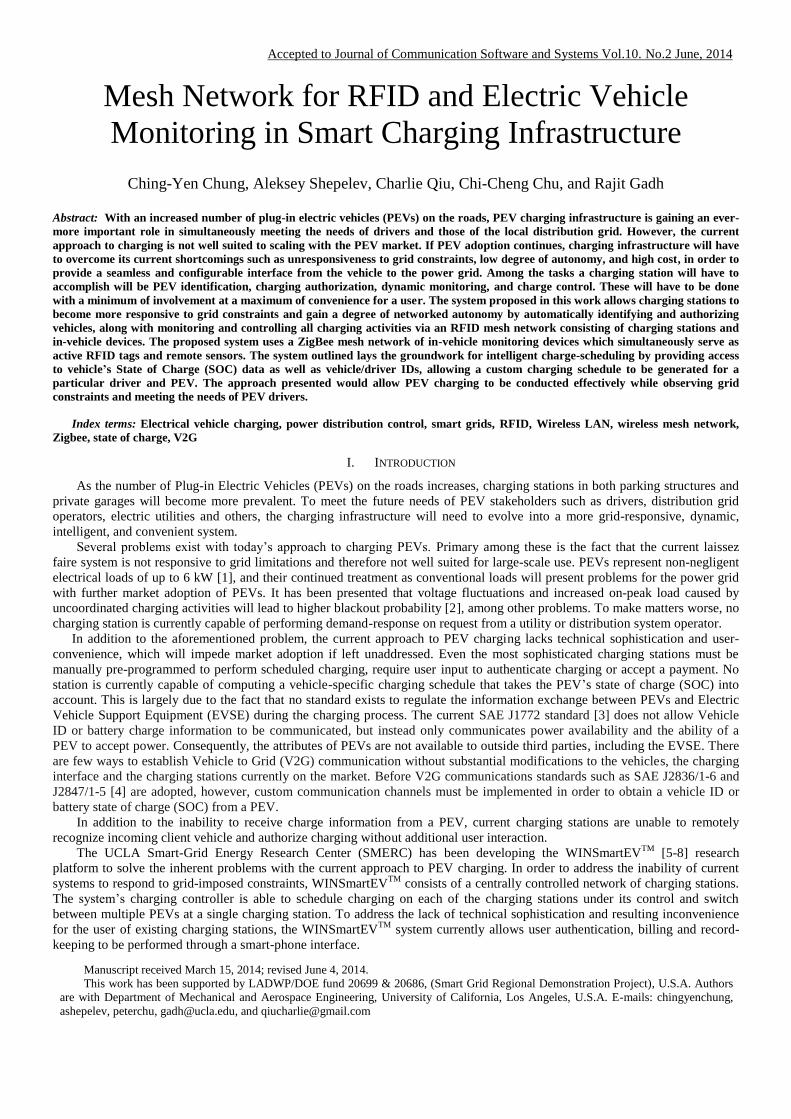
An approaching or departing PEV is recognized by the coordinator using the Received Signal Strength Indication (RSSI)
from the VMMs. Fig. 10 shows the firmware flow of the ZigBee coordinator.
Figure 10. ZigBee coordinator firmware flow [13]
C. Charging Authentication with RFID
Several processes are involved in PEV charging authentication via RFID , including ZigBee MAC address retrieval, user
authorization, and PEV plug-in status detection. Fig. 11 shows a flowchart of the authentication process.

Accepted to Journal of Communication Software and Systems Vol.10. No.2 June, 2014
Figure 11. Charging authentication process using RFID [13]
New PEV arrivals are checked periodically. The server sends out the “rgst” command to check if new tag IDs have been
registered after RFID reader initialization. The “stat” command is later sent out to identify which charging station a newly
arrived PEV is plugged into. If the tag ID corresponds to an authorized user account in the database, the command to enable
charging is sent out to begin PEV charging. All commands are in the following text-based format:
comd[command][channel][parameter]. Details of the command and return values are summarized in Table II.
TABLE II. COMMANDS OF THE CHARGING STATION
Command Description and Example
rgst Return all registered ZigBee MAC address
comdrgst0000
[return]:
rgst01[MAC address][approach/leave/stay]
rgst02[MAC address][approach/leave/stay]
stat Charging station status request
comdstat0100
request channel 1 status
[return]:
duty0150rely0101plug0101stat0100
The aggregate charging server uses EV plug-in status detection to identify the presence of a PEV at a charging station and
to associate the vehicle’s ID with a particular charging receptacle. The PEV plug-in status is monitored on the pilot signal
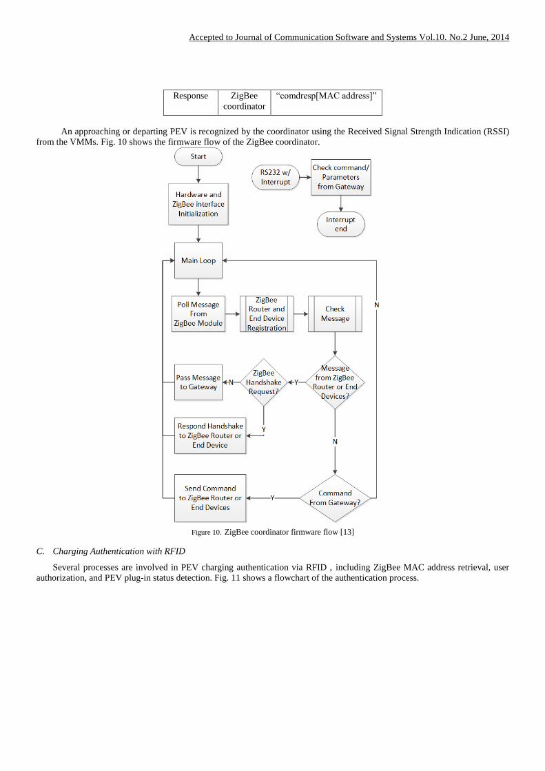
generator/monitor circuit by detecting pilot signal voltage levels set by the PEV. The pilot signal generator circuit is shown in
Fig. 12.
Accepted to Journal of Communication Software and Systems Vol.10. No.2 June, 2014
Figure 12. Implementation of the control unit: (1) Pilot Signal Generator (2) Pilot Signal Monitor (3) 555 counter. (4) Relay Driver. (5)
Schmitt Trigger. (6) Unit Gain Buffer. (7) Inverting Amplifier. (8 )Inverting LPF [13]
The pilot signal generator consists of a Pulse Width Modulation (PWM) signal generator and a Schmitt trigger-based
amplifier. APWM signal is produced, amplified, and transmitted to the PEV. The PEV clips the PWM amplitude, and the
modified signal is watched by the pilot-signal monitor residing on the same circuit. The monitor consists of a de-amplifier and
low-pass filter that produces a DC voltage within AD converter range.
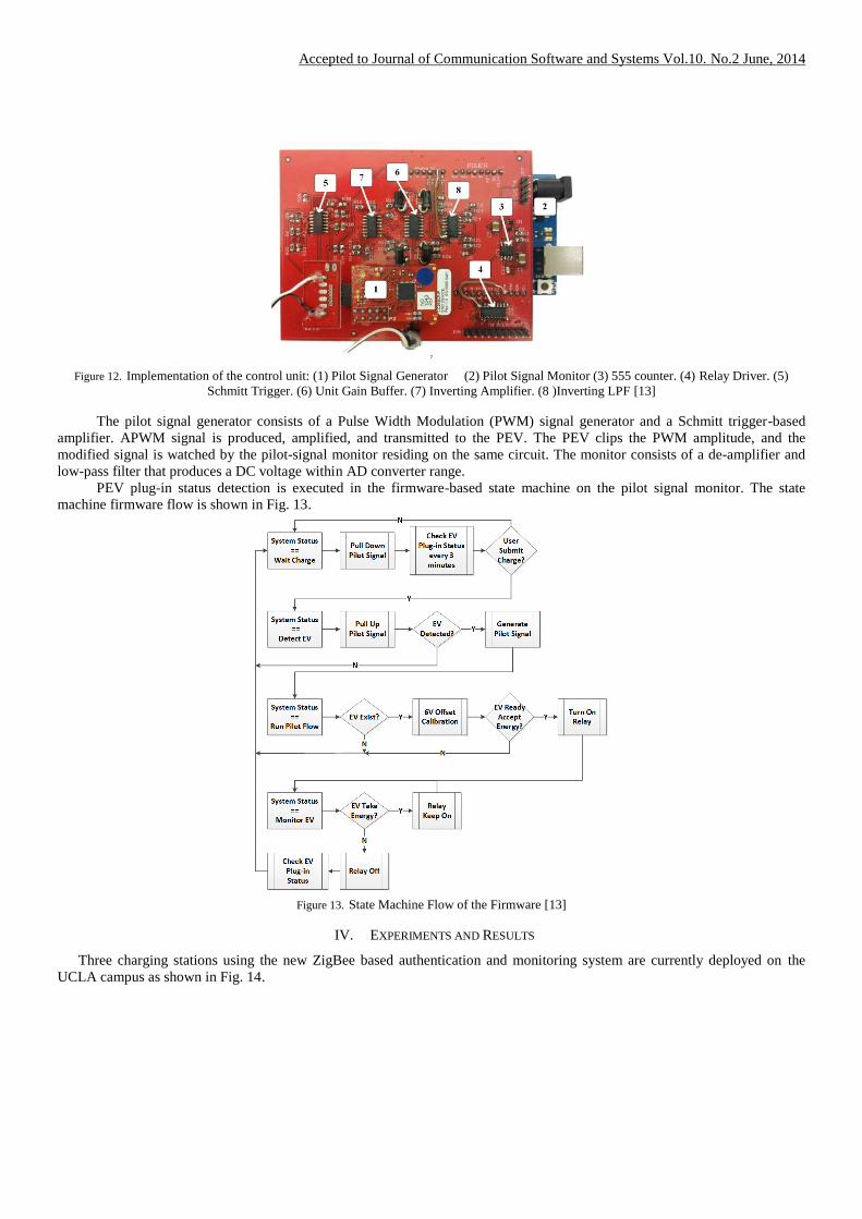
PEV plug-in status detection is executed in the firmware-based state machine on the pilot signal monitor. The state
machine firmware flow is shown in Fig. 13.
Figure 13. State Machine Flow of the Firmware [13]
IV. EXPERIMENTS AND RESULTS
Three charging stations using the new ZigBee based authentication and monitoring system are currently deployed on the
UCLA campus as shown in Fig. 14.
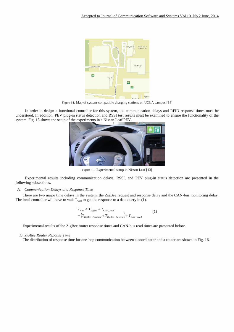
Accepted to Journal of Communication Software and Systems Vol.10. No.2 June, 2014
Figure 14. Map of system-compatible charging stations on UCLA campus [14]
In order to design a functional controller for this system, the communication delays and RFID response times must be
understood. In addition, PEV plug-in status detection and RSSI test results must be examined to ensure the functionality of the
system. Fig. 15 shows the setup of the experiments in a Nissan Leaf PEV.
Figure 15. Experimental setup in Nissan Leaf [13]
Experimental results including communication delays, RSSI, and PEV plug-in status detection are presented in the
following subsections.
A. Communication Delays and Response Time
There are two major time delays in the system: the ZigBee request and response delay and the CAN-bus monitoring delay.
The local controller will have to wait Twait to get the response to a data query in (1).
readCANverseZigBeeForwardZigBee
readCANZigBeewait
TTT
TTT
_Re__
_
(1)
Experimental results of the ZigBee router response times and CAN-bus read times are presented below.
1) ZigBee Router Reponse Time
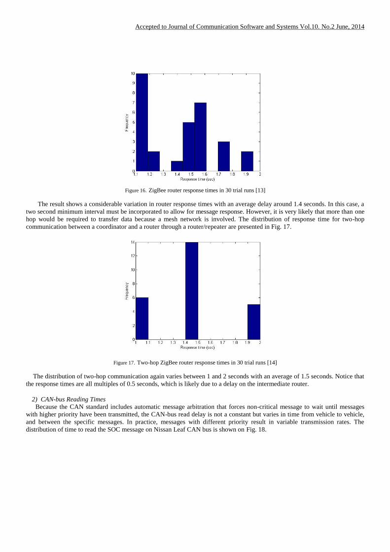
The distribution of response time for one-hop communication between a coordinator and a router are shown in Fig. 16.
Accepted to Journal of Communication Software and Systems Vol.10. No.2 June, 2014
Figure 16. ZigBee router response times in 30 trial runs [13]
The result shows a considerable variation in router response times with an average delay around 1.4 seconds. In this case, a
two second minimum interval must be incorporated to allow for message response. However, it is very likely that more than one
hop would be required to transfer data because a mesh network is involved. The distribution of response time for two-hop
communication between a coordinator and a router through a router/repeater are presented in Fig. 17.
Figure 17. Two-hop ZigBee router response times in 30 trial runs [14]
The distribution of two-hop communication again varies between 1 and 2 seconds with an average of 1.5 seconds. Notice that
the response times are all multiples of 0.5 seconds, which is likely due to a delay on the intermediate router.
2) CAN-bus Reading Times
Because the CAN standard includes automatic message arbitration that forces non-critical message to wait until messages
with higher priority have been transmitted, the CAN-bus read delay is not a constant but varies in time from vehicle to vehicle,
and between the specific messages. In practice, messages with different priority result in variable transmission rates. The
distribution of time to read the SOC message on Nissan Leaf CAN bus is shown on Fig. 18.

Accepted to Journal of Communication Software and Systems Vol.10. No.2 June, 2014
Figure 18. Nissan Leaf CAN bus reading times for 100 trial runs [14]
3) Request Interval
In section IV A., the maximum time for a two-hop response is 2 seconds, which means TZigBee has maximum value of 2
seconds. Considering TCAN_read is with maximum value of 0.1 second, Twait will have to be greater than 2.1 seconds per equation
(1). As a result, 2.1 second minimum waiting interval must be incorporated on the local controller. Therefore, an interval much
larger than 2.1 seconds needs to be incorporated for detecting an approaching PEV. Taking 3G communication delay presented
in [12] into account, the maximum round trip time of 3G is around 5 seconds, which means the server will need to wait 7.1
seconds to receive a response to a data request.
B. PEV Plug-in Status Detection
As per J1772 specification, the duty cycle of the pilot signal indicates available current to the PEV. To ensure the system
works at varying duty cycles, the DC-converted pilot signal was measured for two distinct PEV states: PEV disconnected and
PEV charging. Fig. 19 shows the results of A/D values v.s. duty cycle of pilot signal.
Figure 19. A/D Value v.s. Duty Cycle of Pilot Signal [13]
The DC values measured at the A/D converter are clearly distinguishable in these two cases and have good linearity. The
resolution is more than sufficient to detect the PEV’s plug-in status even when the duty cycle is around 10%, which indicates a
6A charge current, or the minimum current set by J1772 specification. The average value of these two cases is set to be the
threshold value for PEV plug-in status detection.
C. Approaching and Leaving Detemination
The RSSI is used to identify an approaching or departing PEV to and from a charging station. Fig. 20 shows the results of
RSSI vs. distance between the charging station and the PEV.

Accepted to Journal of Communication Software and Systems Vol.10. No.2 June, 2014
Figure 20. RSSI v.s. Distance between two charging station and the PEV [13]
When the PEV is within 50 meters of the charging station, the RSSI has a sudden jump from -89 dBm to -77dBm, which
means the PEV is likely to be detected in this range. Notice that there is another jump in RSSI when the PEV approaches within
20 meters, which implies that RSSI would be an appropriate metric for PEV approaching identification.
In most cases, the accepted speed limit in parking lot is 5 mph, which means a PEV approaches a charging station by 4.5
meters every 2 seconds. Assuming that the PEV parks 5 meters away from the charging station, after a PEV is detected at a
distance of 50 meters, the station will have a maximum of 10 handshakes to determine whether the PEV is approaching or
leaving.
D. Collaboration between Server and Stations
The RFID authentication and authorization control scheme involves collaboration between a master controller (server) and a
local controller (ZigBee coordinator). In the 3G case, we measure status retrieval TRoundTrip distributions of three charging
stations in different locations at UCLA in second, third, fourth charts in Fig. 21. As a baseline the first chart in Fig. 21 shows
round trip status retrieval via Ethernet connection.
Figure 21. Status Retrieval Round Trip Time
The experiments show that T3G is not a constant offset from the Ethernet case but a distribution probability with two peaks
measured in its distribution. In order to accelerate the performance of the system, the local controller will need to be modified to
push data to the master controller. Instead of the server periodically sending “rgst” commands to retrieve new tag IDs from the
ZigBee coordinator, the coordinator will push newly detected tag IDs to the database. Assuming the 3G uplink time is half of
round trip time, the interval of new tag ID detection can be shortened by half. In addition, the traffic between the server and the
station can also be reduced.
The local controller inside the charging station sends the trigger signal on change of PEV plug-in status. Once a new PEV
plug-in status is detected, the local controller pushes the status and corresponding tag ID to the database. If the tag ID matches
an authorized user account in the database, the command to begin PEV charging is sent.
Accepted to Journal of Communication Software and Systems Vol.10. No.2 June, 2014
E. Exception Handling
When more than two PEVs arrive at the same charging station around the same time, the charging station may not have a way
to associate their IDs with the corresponding outlets. In this case, the server needs an exception handling process to handle the
charging sessions.
If the arriving PEVs have different on-board charger size, the charging station will be able to associate the IDs with outlets
due to differences in charging current. However, if PEVs have same size on board chargers, the server will not be able to
associate the IDs with their respective electrical outlets at the start of charging. The server will still be able to associate the
charging sessions with IDs and outlets when the PEVs leave by detecting PEV’s RSSI. If the PEVs are fully charged before they
leave, the server will associate the IDs and outlets by SOC when PEVs are fully charged. If the PEVs with same size on board
chargers arrive and leave around the same time without fully charged, there is no need to distinguish the charging session
because their drivers will be billed for the same energy consumption
V. CONCLUSION
A convenient method for charge authorization and monitoring is provided by the ZigBee-based system proposed above. An
approach utilizing a remote identification tag and charging station-based reader allows authorization/identification and charge-
monitoring capability to be added to the existing WINSmartEVTM
charging infrastructure without excessive modification to the
PEV or the charging station. Plug-in VMM modules allow PEVs to be made easily compatible with the system while retaining
compliance with the J1772 standard. Use of a mesh network allows a robust connection to be maintained between charging
stations and PEVs in a real world environment subject to signal blocking conditions. Charge-monitoring capability allows a
controller to access a PEV’s state of charge and facilitates generation of charging schedules tailored to a particular vehicle and
driver.
The aforementioned improvements described in this work bring WINSmartEVTM
infrastructure closer to an economical and
user friendly smart charging technology that enhances the stability and reliability of the local grid while meeting the
convenience needs of PEV drivers.
VI. ACKNOWLEDGEMENT
This work has been sponsored in part by a grant from the LADWP/DOE fund 20699 & 20686, (Smart Grid Regional
Demonstration Project). This material is based upon work supported by the United States Department of Energy under Award
Number DE-OE000012 and the Los Angeles Department of Water and Power. Neither the United States Government nor any
agency thereof, the Los Angeles Department of Water and Power, nor any of their employees make any warranty, express or
implied, or assumes any legal liability or responsibility for the accuracy, completeness, or usefulness of any information,
apparatus, product, or process disclosed, or represents that its use would not infringe privately owned rights.
Reference herein to any specific commercial product, process, or service by trade name, trademark, manufacturer, or
otherwise does not necessarily constitute or imply its endorsement, recommendation, or favoring by the United States
Government or any agency thereof. The views and opinions of authors expressed herein do not necessarily state or reflect those
of the United States government or any agency thereof.
REFERENCES
[1] S. Hadley and A. Tsvetkova: “Potential impacts of plug-in hybrid electric vehicles on regional power generation”, Oak Ridge National
Laboratory, Tech. Rep., 2008.
[2] S. Deilami, A. Masoum, P. Moses, and M. Masoum: “Real-time coordination of plug-in electric vehicle charging in smart grids to
minimize power losses and improve voltage profile”, IEEE Trans. Smart Grid, vol. 2, no. 3, Sept. 2011, p.p. 456-467.
[3] “SAE Electric Vehicle and Plug in Hybrid Electric Vehicle Conductive Charge Coupler,” SAE International Surface Vehicle
Recommended Practice. (http://standards.sae.org/j1772_201210//) [03/11/2014]
[4] SAE International Standards for Electric Vehicle (http://topics.sae.org/electric-vehicles/standards/) [03/11/2014]
[5] Rajit Gadh et al.: “Smart electric vehicle (ev) charging and grid integration apparatus and methods”, US Patent, PCT International Patent,
Ser. No. US20130179061A1, WO2011156776A2, WO2011156776A3, PCT/US2011/040077, US13/693, Jun. 10, 2010.
[6] Rajit Gadh et al.: “Intelligent electric vehicle charging system”, US Patent, PCT International Patent, Ser. No. WO2013019989A2,
WO2013019989A3, PCT/US2012/049393 (2 August, 2011)
[7] Rajit Gadh et al.: ” Network based management for multiplexed electric vehicle charging”, US Patent, PCT International Patent, Ser. No.
US20130154561A1, US13/691,709, Nov. 30, 2011.
[8] C. Chung, P. Chu, R. Gadh: “Design of Smart Charging Infrastructure Hardware And Firmware Design of The Various Current
Multiplexing Charging System“, Seventh Global Conference on Power Control and Optimization PCO2013, Prague, Aug. 25-27, 2013.
[9] R. Lowenthal, D. Baxter, H. Bhade, P. Mandal: "Network-controlled charging system for electric vehicles", US Patent US7956570B2,
Jun. 7, 2011.
[10] D. Baxter, H. Bhade, R. Lowenthal, P. Mandal: "Network-controlled charging system for electric vehicles through use of a remote server",
US Patent US8138715B2, Mar. 20, 2012.
[11] X. Su, C. Chu, B.S. Prabhu, and R. Gadh: “On the Identification Device Management and Data Capture via WinRFID Edge-Server”,
IEEE Systems Journal, 1(2), Dec 2007, p.p. 95-104.

Accepted to Journal of Communication Software and Systems Vol.10. No.2 June, 2014
[12] C. Chung, J. Chynoweth, C. Qiu, C. Chu, R. Gadh: "Design of Fast Response Smart Electric Vehicle Charging Infrastructure", IEEE
Green Energy and Systems Conference, IGESC 2013, Long Beach, U.S.A., Nov. 25, 2013.
[13] C. Chung, A. Shepelev, C. Qiu, C. Chu, R. Gadh: “Design of RFID Mesh Network for Electric Vehicle Smart Charging Infrastructure”,
2013 IEEE International Conference on RFID Technologies and Applications, Johor Bahru, Malaysia, Sept. 4 – 5, 2013.
[14] A. Shepelev, C. Chung, C. Chu, R. Gadh: "Mesh Network Design for Smart Charging Infrastructure and Electric Vehicle Remote
Monitoring", International Conference on ICT Convergence 2013, Jeju, Korea, Oct. 14-16, 2013.
BIOGRAPHIES
Ching-Yen Chung received his PhD in the Department of Mechanical Engineering, University of California, Los
Angeles in 2014. He received his BS and MS degrees in Mechanical Engineering from National Taiwan University in
Taiwan in 2002 and 2004. He had worked for the LITE-ON IT Corporation, an optical disc drive manufacturer, for five
years. He received the university fellowship from UCLA graduate division in 2009 and 2012. He received the best paper
bronze award in IEEE RFID TA conference in 2013. He is currently developing the architecture for smart grid in
WINMEC (Wireless Internet for Mobile Enterprise Consortium) Lab conducted by Professor Rajit Gadh.
Aleksey Shepelev received his BS in Mechanical Engineering from UC Berkeley and his MS in Mechanical
Engineering from UCLA. He has worked to develop smart-charging and monitorning solutions for future PEV charging
architecture under the direction of Dr. Rajit Gadh. He co-authored a paper that received the best paper bronze award in
IEEE RFID TA conference in 2013.
Charlie Qiu is presently a RESEARCHER at the Henry Samueli School of Engineering and Applied Science at
University of California at Los Angeles. He has over 10 years of experience in RESEARCH AND DEVELOPMENT of
software architectures, frameworks and solutions and has delivered multiple project solutions and software packages to
the industry globally.
Chi-Cheng Chu received his PhD from University of Wisconsin – Madison on 2001 and BS form National Taiwan
University on 1990. Dr. Chu is currently a project lead at Henry Samueli School of Engineering and Applied Science at
University of California at Los Angeles. He is also the forum convener at UCLA WINMEC consortium. He has 2
patents attributed under his name and published more than 40 papers in professional engineering and scientific journals,
books, and conference proceedings. He received one Best Paper Award in Excellence for Applied Research at 2004
Wireless Telecommunications Symposium.
Rajit Gadh is a Professor at the Henry Samueli School of Engineering and Applied Science at UCLA, and the Founding
Director of the UCLA Smart Grid Energy Research Center (SMERC) and the Wireless Internet for Mobile Enterprise
Consortium (WINMEC). He has over 150 papers in journals, conferences and technical magazines. He has a Doctorate
degree from Carnegie Mellon University (CMU), a Masters from Cornell University and a Bachelor's degree from IIT
Kanpur. He has won several awards from NSF, SAE, IEEE, ASME, AT&T, Engineering Education Foundation,
William Wong Fellowship award from University of Hong-Kong, ALCOA Science Support Scholar.