mesh geometry compression for mobile...
TRANSCRIPT
Mesh Geometry Compression for Mobile GraphicsJongseok Lee
Sungyul ChoeSamsung Electronics
Seungyong LeePOSTECH
Abstract—This paper presents a compression scheme for meshgeometry, which is suitable for mobile graphics. The main focus isto enable real-time decoding of compressed vertex positions whileproviding reasonable compression ratios. Our scheme is basedon local quantization of vertex positions with mesh partitioning.To prevent visual seams along the partitioning boundaries, weconstrain the locally quantized cells of all mesh partitions tohave the same size and aligned local axes. We propose a meshpartitioning algorithm to minimize the size of locally quantizedcells, which relates to the distortion of a restored mesh. Vertexcoordinates are stored in main memory and transmitted tographics hardware for rendering in the quantized form, savingmemory space and system bus bandwidth. Decoding operationis combined with model geometry transformation, and the onlyoverhead to restore vertex positions is one matrix multiplicationfor each mesh partition.
Index Terms—Mesh compression, Geometry encoding, Mobilegraphics, Local quantization, Mesh partitioning.
I. INTRODUCTION
Recent mobile devices, such as mobil phones, PDAs, andhand-held game players, are equipped with quite decent fea-tures of computing power, storage, graphics, and network. Es-pecially, for mobile graphics, API standards such as OpenGLES and JSR-184 have been proposed [8], and the graphicsperformance has been drastically improved with developmentof mobile GPUs. However, compared to desktop PC graphics,mobile graphics is still constrained by limited resources oflow computing powers, small amounts of memory, and lowbandwidths. In addition, while mobile devices are usuallypowered by batteries, battery technology has not caught upwith the energy requirement of 3D graphics processing.
Data compression can provide an excellent solution to helpovercome these limitations. Obviously, compressed graphicsdata enable us to better utilize storage space and networkbandwidth. Furthermore, by decoding compressed data on-the-fly on graphics hardware [11], we can reduce memoryaccess and data transmission through the system bus, whichsaves power consumption. However, to be suitable for mobilegraphics, a compression technique should be simple enoughnot to impose a big overhead on the low computing power.
In this paper, we propose a simple and effective compressiontechnique for mesh geometry, which can be used for mobilegraphics in practice. The main design objective is real-timeon-the-fly decoding of vertex positions on graphics hardware.Such property enables the compressed form to be used for bothstoring the vertex positions of a mesh in main memory andtransmitting to graphics hardware for rendering. As a result,main memory space and system bus bandwidth required formesh geometry can be reduced in a rendering system.
To fulfill the objective, we use local quantization of vertexpositions with mesh partitioning. However, straightforward lo-cal quantization that processes each mesh partition separatelysuffers from visual seams along the partitioning boundariesof the restored mesh. To prevent the problem, we quantizeall mesh partitions in a coherent way to have the same-sizedand axis-aligned quantized cells. Then, the distortion of therestored mesh relates with the size of the quantized cells andwe propose a mesh partitioning algorithm to minimize the size.
The setting of our experiments is to quantize a 32-bitfloating point vertex coordinate into an 8-bit integer, which isthe smallest data size supported in a mobile graphics library.Local quantization incurs encoding overhead for boundingcube information and duplicated vertices. However, experi-mental results show that the data reduction ratios are still over70%. The distortions of the restored meshes are comparableto 11-bit global quantization of vertex coordinates, which isclose to 12-bit global quantization that is considered enoughfor representing the geometry of moderate-sized meshes inmesh compression [1], [7].
II. RELATED WORK
Mesh compression has been an active research area ingraphics. A comprehensive review of mesh compression tech-niques, which is not within the scope of this paper, can befound in excellent survey papers [1], [7].
Although previous mesh compression algorithms offer goodperformance in compression ratio, their encoding and decod-ing processes are rather complicated and can impose muchoverhead on the relatively low computing power of mobilehardware. More importantly, most of them sequentially tra-verse mesh elements for encoding, which prohibits paralleldecoding of encoded elements on graphics hardware. Conse-quently, previous algorithms cannot be directly adopted formesh compression on mobile devices.
Calver [2] described the basic principles for various quan-tization methods of vertex geometry which allow real-timedecoding with programmable vertex shaders. He mentionedthat local quantization can be used for vertex geometry to ob-tain better compression rate-distortion. However, he presentedno solution for the problem of visual seams and no specifictechnique to partition a given mesh for local quantization.
Purnomo et al. [9] refine the idea of Calver and allocatedifferent numbers of bits for the components of vertex at-tributes, such as positions, normals, and texture coordinates,to minimize the image-space error. At rendering time, com-pressed vertex data, which have been packed into fixed 96 bits,

are transmitted to a programmable vertex shader and restoredon-the-fly. However, in terms of vertex geometry compression,their technique uses global quantization, which provides worsecompression rate-distortion than local quantization.
In contrast to [2], in this paper, we provide effectivesolutions to handle visual seams and mesh partitioning forlocal quantization. Compared to [9], in addition to the dif-ference of using local quantization, our technique requires noprogrammable vertex shader because the decoding operationcan be incorporated into the standard geometry transformation,which makes it applicable to a wide range of mobile graphicsplatforms.
III. BASIC IDEA
In this paper, we only consider compression of mesh ge-ometry. We assume that mesh connectivity is represented inan adequate form (e.g., triangle strips), which is supported inmobile graphics API standards, such as JSR-184 [8].
To restore vertex geometry in real time on a mobile device, acompression algorithm should satisfy the following properties;• The decoding process is simple enough for real-time
performance.• The decoding operations of vertex positions have no de-
pendency among each other to allow parallel processing.• Encoded data are represented in a fixed-size format,
which matches with the data channel size between CPUand graphics hardware.
A simple solution to satisfy these requirements is thequantization of vertex positions. Original vertex positions,represented by 32-bit floating point numbers, can be encodedwith fewer bits by truncating least significant bits. We caneasily restore the original positions from the quantized onesby simple additions and multiplications. In addition, there isno dependency among quantized vertex positions.
In compression of irregular meshes with reasonable sizes,12-bit global quantization is assumed to introduce no strongvisual artifacts and used as a preprocessing step before geom-etry encoding [1], [7]. However, the use of 12-bit quantizedpositions can cause unnecessary bitwise operations or wasteof bandwidth because most graphics APIs support only fixed-sized data channels (e.g., 8, 16, and 32 bits). On the otherhand, if we globally quantize vertex positions with 8 bits, wemay have severe distortions of mesh geometry (see Fig. 7(a)).
To resolve such a problem, Calver [2] described a localquantization method. A mesh is divided into several sub-meshes and each sub-mesh is independently quantized. Then,the distortion of the restored mesh is reduced because the sizeof a bounding cube, which is the range of quantization, de-creases. As a result, 8-bit local quantization of mesh geometrycan provide better accuracy for restored vertex positions thanglobal quantization (see Fig. 7(b)). However, in this case, therestored mesh contains a critical problem, i.e., visual seamsalong the sub-mesh boundaries, as shown in Fig. III(b). Calver[2] did not provide any solution to handle the problem.
The main cause of the visual seam problem is that sharedboundary vertices of sub-meshes should be encoded more than
(a) (b) (c)Fig. 1. (a) Rendering of a horse model. (b) and (c) show zoom-ins of thered rectangle in (a); (b) Visual seams from straightforward local quantization.(c) Visual seams have been resolved by our method.
(a) analysis (b) our solutionFig. 2. (a) A black vertex shared by two sub-meshes is restored onto thegreen and red positions due to the difference of locally quantized cells. (b)The restored positions from two sub-meshes have become the same due tothe alignment of locally quantized cells.
once. Sub-meshes are disjoint subsets of mesh faces and aboundary vertex of a sub-mesh also belongs to one or moreother sub-meshes, except at the mesh boundary. When sub-meshes are separately encoded, a boundary vertex v sharedamong k sub-meshes is encoded k times, once for each sub-mesh, with different local quantization. At decoding time, arestored vertex position is the center of a quantized cell. Therestored positions of v in the k sub-meshes do not match eachother if the corresponding locally quantized cells of the sub-meshes are not aligned. See Fig. III(a) for illustration.
The basic idea of our solution for the visual seam problemis to align the locally quantized cells of sub-meshes sharingboundary vertices. As illustrated in Fig. III(b), if the locallyquantized cells are aligned, the restored positions of a sharedvertex will be the same among the sub-meshes. This con-straint of aligned quantized cells should hold for every pairof sub-meshes sharing a boundary vertex. Consequently, theconstraint propagates through the adjacency of sub-meshes,and the locally quantized cells of all sub-meshes should havethe same size and aligned axes. In this paper, we use the largestbounding cube of sub-meshes to determine the cell size andaxes of the aligned local quantization, which is then appliedto all sub-meshes. Fig. III(c) shows that the rendering resultfrom our local quantization method does not contain any visualseams.
IV. ENCODING PROCESS
The encoding process consists of two parts; mesh partition-ing, which divides an input mesh into several sub-meshes, andlocal quantization of vertex positions, which uses the meshpartitioning result.
A. Mesh partitioningWith quantization of vertex positions, the distortion of a
restored mesh from the original is dominated by the size ofquantized cells. As described in Sec. III, in our approach, thesize of locally quantized cells is determined by the largestbounding cube of mesh partitions. Hence, to minimize thedistortion, the largest bounding cube should be made as smallas possible.
We adapt the mesh partitioning framework based on Lloyd’salgorithm [6], which has been successfully used for meshsegmentation [10], [3]. After initial partitioning has beenobtained with a given number of partitions, the partitioningresult is iteratively updated by repeating two steps; seed re-computation and region growing. In the seed re-computationstep, the seed triangles are repositioned at the centers ofpartitions for the next update. In the region growing step, facesare added to partitions in the increasing order of distances fromthe nearest seed faces.
For initial partitioning, we use the hierarchical face clustermerging approach [5]. At the beginning, each face is a singlepartition. We iteratively merge two neighbor partitions into oneuntil the number of partitions is reduced to the desired number.To select the merged pair of partitions at each iteration, weuse the cost function defined by
F (Ci, Cj) = max{xij , yij , zij}, (1)
where xij , yij , and zij are respectively the x, y, and z sizes ofthe axis aligned bounding cube containing the two partitions,Ci and Cj . By minimizing F (Ci, Cj), we can reduce thebounding cube sizes of resulting mesh partitions.
For seed-recomputation and region growing, we use L∞metric to define the distance function. To reposition the seed ofa mesh partition, we first compute the center of the boundingcube of the partition, which can be considered as the L∞center of the partition. Although we can use the center as thenew seed of the partition, we select the nearest face to thecenter as the new seed face because we use the adjacency offaces in region growing for efficiency. In region growing, thedistance of a face f from the seed face of a partition C isdefined by
F (f, C) = max{δx, δy, δz}, (2)
where δx is the maximum of the x-distances of three verticesof f from the center of the seed face of C. δy and δz aredefined similarly.
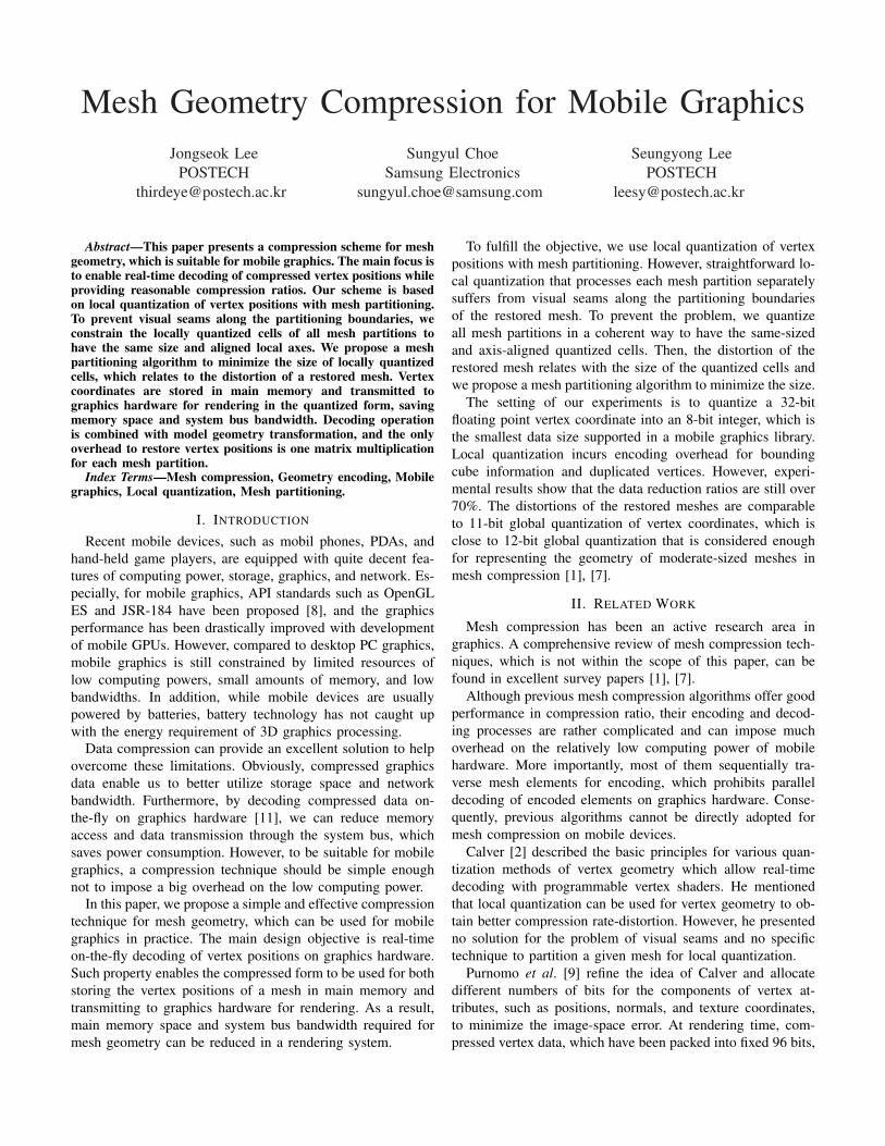
In mesh segmentation techniques [10], [3], it has beendemonstrated that the result of Lloyd’s algorithm partitionsa given mesh into almost equal-sized sub-meshes, where thesize is measured in the adopted distance function. Similarly,with L∞ metric, we can expect that the sub-meshes resultingfrom Lloyd’s algorithm have almost same sizes of boundingcubes because a L∞ sphere in 3D is a cube. As a result, thelargest bounding cube of mesh partitions can be made as smallas possible for a given number of partitions. Fig. IV-A showsexamples of the final partitioning result.
B. Local quantizationIn this paper, we use 8-bit quantization for vertex coordi-
nates. The steps for local quantization can be summarized asfollows;
Fig. 3. Mesh partitioning results
1) Calculate the bounding cube for each mesh partition and findthe largest x, y, and z bounding cube sizes among all partitions.
2) Calculate (Cx, Cy, Cz), the x, y, and z sizes of the quantizedcell, by dividing the largest x, y, and z bounding cube sizesby (28 − 1), respectively.
3) Quantize all vertex positions by dividing original vertex coor-dinates by the quantized cell size (Cx, Cy, Cz) and truncatingthe fractional values.
4) For each partition, find the minimum quantized coordinatesfor the x, y, and z axes, and keep the values as the offsets(Ox, Oy, Oz). Then, subtract (Ox, Oy, Oz) from the quantizedcoordinates of vertices, obtaining the final quantized coordi-nates (Px, Py, Pz) in the range of [0, 255].
5) Save the size of the quantized cell, offsets for partitions, andquantized vertex positions.
Note that for calculating the size of the quantized cell, weuse (28 − 1), instead of 28, to guarantee that the quantizedvertex coordinates after offsetting fall in the range of [0, 255].
C. File structure
After local quantization, to restore vertex positions, weneed the size of the quantized cell, offsets for partitions, andquantized vertex positions. The size of the quantized cell isstored only once for a mesh and represented by three 32-bit floating point numbers. The offsets for a mesh partitioncorrespond to the quantized coordinates of the origin of thebounding cube of the partition. To represent the offsets, we use16 to 32-bit integers depending on the mesh size. Since weare using 8-bit local quantization, a quantized vertex positionrequires 24 bits, i.e., three 8-bit unsigned integers. In addition,we should record the number of partitions and the number ofvertices in each partition. These numbers are represented by16 to 32-bit integers depending on the mesh size. Fig. 4 showsthe file structure that contains encoded mesh geometry.
There are two kinds of storage overhead incurred by en-coding with local quantization. One is the header overhead,which corresponds to the data in the mesh header and partitionheaders in Fig. 4. The other is the vertex overhead. Asmentioned in Sec. III, the boundary vertices shared among sub-meshes should be duplicated when they are locally quantizedwith different offsets. Hence, in the encoded mesh geometry,there are more quantized vertex positions than the number ofvertices.
V. DECODING PROCESS
When we render a mesh with encoded geometry, we firstrestore the quantized cell size (Cx, Cy, Cz) from the mesh

/GUJ�)GQOGVT[�(KNG
0HVK�+HDGHU
3DUWLWLRQ�+HDGHU
9HUWH[3RVLWLRQV
3DUWLWLRQ��+HDGHU
9HUWH[3RVLWLRQV
�
/GUJ�*GCFGT
&[ &\ &] ��RI�SDUWLWLRQV
+HDGHU +HDGHU 3RVLWLRQV +HDGHU 3RVLWLRQV
��E\WHV ��E\WHV �E\WHV ����E\WHV
2CTVKVKQP�*GCFGT
2[ 2\ 2] � RI YHUWLFHV2[ 2\ 2] ��RI�YHUWLFHV
����E\WHV ����E\WHV ���E\WHV ����E\WHV
8GTVGZ�2QUKVKQP
3[ 3\ 3]
��E\WH ��E\WH ��E\WH
Fig. 4. File structure for encoded mesh geometry: C, O, and P denote thequantized cell size, offset value, and vertex coordinate, respectively.
header. Then, each partition of the mesh is rendered with thefollowing procedure;
1) Restore the offset values (Ox, Oy, Oz) from the partitionheader.
2) Calculate a 4× 4 decoding matrix
Md =
Cx 0 0 Cx ·Ox
0 Cy 0 Cy ·Oy
0 0 Cz Cz ·Oz
0 0 0 1
. (3)
3) Multiply matrix Md by the geometry transformationmatrix, e.g., the model-view matrix in OpenGL.
4) Render the polygons in the partition.In the decoding process, vertex geometry data are transmit-
ted from main memory to graphics hardware in the encodedform, i.e., an 8-bit integer for a vertex coordinate. Whenwe render a polygon, the vertex positions are automaticallyrestored through the geometry transformation matrix whichhas been modified by the decoding matrix Md. Note that Md
is the composition of two matrices, one for adding offsetsto locally quantized vertex coordinates in [0, 255] and theother for multiplying the quantized cell size by the quantizedcoordinates after offsetting to obtain 32-bit floating pointcoordinates.
Our decoding process is nicely incorporated into the stan-dard rendering pipeline. As a result, at rendering time, theonly major overhead is one matrix multiplication per a parti-tion, which can be considered negligible. Although boundaryvertices are duplicated among partitions, the number of ren-dered polygons does not change and the number of verticesprocessed for rendering remains the same.
VI. EXPERIMENTAL RESULTS
We have implemented and tested our algorithm using avariety versions of Khronos OpenGL graphics APIs [8], suchas OpenGL 1.x, OpenGL 2.x, and OpenGL ES 2.x emulator. InOpenGL 1.x and OpenGL 2.x implementations, the decodingmatrix Md is formed and multiplied by the model-view matrixbefore rendering each sub-mesh. For OpenGL ES 2.x emulator,Md is formed and used when we set up a vertex shader fora sub-mesh. Fig. 5 shows models used in our experiments.
In the experiments, we measure the reduction ratio forvertex geometry data. We also count the number of duplicated
Fig. 5. Models used in our experiments. From the top left in the clockwiseorder, children, dancer, feline, filigree, horse, and squirrel.
Distortion Data Reduction Ratio Vertex Overhead
463
Distortion Data�Reduction�Ratio Vertex�Overhead
366338
222
72.9 71.9 70.3 67.9
7.7 11.7 17.2 24.7
32 64 128 256��RCTVKVKQPU
Fig. 6. Compression results with different numbers of partitions for dancermodel. Distortions are shown in the unit of 10−6.
vertices along the boundaries of mesh partitions. That is,
Data Reduction Ratio =
(1− compressed data
uncompressed data
)× 100
V ertex Overhead =# of duplicated vertices
# of vertices× 100
The distortion of a mesh restored from encoded geometryis measured from the original mesh in the average L2 normusing the Metro tool [4].
Fig. 6 shows the distortions, data reduction ratios, andvertex overheads for increasing numbers of partitions withthe dancer model. When the number of partitions becomeslarger, the data reduction ratio decreases because we need tostore more partition headers and the vertex overhead increases.In contrast, the distortion of the restored mesh is reducedwith more partitions because the bounding cubes of partitionsbecome smaller, which increases the accuracy of quantization.As we can expect, such tendency appeared for all models inour experiments.
Table I shows the distortions of restored meshes withdifferent quantization methods. As shown in Fig. 6, the dis-tortion from our local quantization varies with the number ofpartitions. In Table I, we use the number of partitions whichprovides 70% (+0.1) data reduction ratio. Table I shows thatthe distortion of 8-bit local quantization is quite less than thatof 8-bit global quantization for every model. In addition, therestored quality of 8-bit local quantization is better than orsimilar to 11-bit global quantization in most cases, except theSquirrel model which is the smallest.
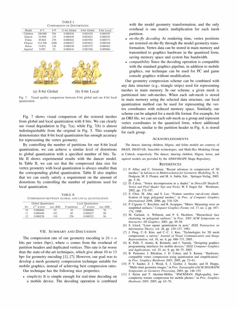
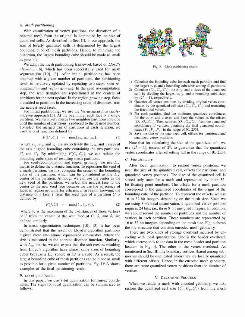
TABLE ICOMPARISON OF DISTORTIONS
Model # V # P 11-bit Global 8-bit Global 8-bit LocalChildren 100,000 564 0.000436 0.003429 0.000395Dancer 24,998 135 0.000449 0.003622 0.000293Feline 49,864 270 0.000442 0.003583 0.000373
Filigree 514,300 2480 0.000452 0.003642 0.000160Horse 19,851 128 0.000430 0.003375 0.000462
Squirrel 9,995 52 0.000416 0.003360 0.000966
(a) 8-bit Global (b) 8-bit LocalFig. 7. Visual quality comparison between 8-bit global and our 8-bit localquantization.
Fig. 7 shows visual comparison of the restored meshesfrom global and local quantization with 8 bits. We can clearlysee visual degradation in Fig. 7(a), while Fig. 7(b) is almostindistinguishable from the original in Fig. 5. This exampledemonstrates that 8-bit local quantization has enough accuracyfor representing the vertex geometry.
By controlling the number of partitions for our 8-bit localquantization, we can achieve a similar level of distortionsto global quantization with a specified number of bits. Ta-ble II shows experimental results with the dancer model.In Table II, we can see that the compressed data size forvertex geometry with local quantization is always smaller thanthe corresponding global quantization. Table II also impliesthat we can easily satisfy a requirement on the amount ofdistortions by controlling the number of partitions used forlocal quantization.
TABLE IICOMPARISON BETWEEN GLOBAL AND LOCAL QUANTIZATION
Global Quantization Local Quantizationb/v L2 d-error size (KB) # partitions L2 d-error size (KB)10 0.000884 92 10 0.000840 7611 0.000449 101 40 0.000427 8012 0.000228 110 256 0.000222 94
VII. SUMMARY AND DISCUSSION
The compression rate of our geometry encoding is 24 + αbits per vertex (bpv), where α comes from the overhead ofpartition headers and duplicated vertices. This rate is far worsethan the state-of-the-art techniques, which give about 10 to 13bpv for geometry encoding [1], [7]. However, our goal was todevelop a mesh geometry compression technique suitable formobile graphics, instead of achieving best compression rates.
Our technique has the following nice properties;• simplicity It is simple enough for real-time decoding on
a mobile device. The decoding operation is combined
with the model geometry transformation, and the onlyoverhead is one matrix multiplication for each meshpartition.
• on-the-fly decoding At rendering time, vertex positionsare restored on-the-fly through the model geometry trans-formation. Vertex data can be stored in main memory andtransmitted to graphics hardware in the quantized form,saving memory space and system bus bandwidth.
• compatibility Since the decoding operation is compatiblewith the standard graphics pipeline, in addition to mobilegraphics, our technique can be used for PC and gameconsole graphics without modification.
Our geometry compression scheme can be combined withany data structure (e.g., triangle strips) used for representingmeshes in main memory. In our scheme, a given mesh ispartitioned into sub-meshes. When each sub-mesh is storedin main memory using the selected data structure, our localquantization method can be used for representing the ver-tex coordinates with reduced memory space. Similarly, ourscheme can be adapted for a mesh file format. For example, foran OBJ file, we can set each sub-mesh as a group and representvertex coordinates in the quantized form, where additionalinformation, similar to the partition header in Fig. 4, is storedfor each group.
ACKNOWLEDGMENTS
The dancer, dancing children, filigree, and feline models are courtesy ofIMATI, IMATI-GE, SensAble technologies, and Multi-Res Modeling Groupat Caltech, respectively. The dancer, dancing children, filigree, horse, andsquirrel models are provided by the AIM@SHAPE Shape Repository.
REFERENCES
[1] P. Alliez and C. Gotsman, “Recent advances in compression of 3Dmeshes,” in Advances in Multiresolution for Geometric Modelling, N. A.Dodgson, M. S. Floater, and M. A. Sabin, Eds. Springer-Verlag, 2005,pp. 3–26.
[2] D. Calver, “Vertex decompression in a shader,” in Direct3D ShaderX:Vertex and Pixel Shader Tips and Tricks, W. F. Engel, Ed. Wordware,2002, pp. 172–187.
[3] S. Choe, M. Ahn, and S. Lee, “Feature sensitive out-of-core charti-fication of large polygonal meshes,” in Proc. of Computer GraphicsInternational 2006, 2006, pp. 518–529.
[4] P. Cignoni, C. Rocchini, and R. Scopigno, “Metro: Measuring error onsimplified surfaces,” Computer Graphics Forum, vol. 17, no. 2, pp. 167–174, 1998.
[5] M. Garland, A. Willmott, and P. S. Heckbert, “Hierarchical faceclustering on polygonal surfaces,” in Proc. 2001 ACM Symposium onInteractive 3D Graphics, 2001, pp. 49–58.
[6] S. Lloyd, “Least square quantization in pcm,” IEEE Transaction onInformation Theory, vol. 28, pp. 129–137, 1982.
[7] J. Peng, C.-S. Kim, and C.-C. J. Kuo, “Technologies for 3D meshcompression: a survey,” Journal of Visual Communication and ImageRepresentation, vol. 16, no. 6, pp. 688–733, 2005.
[8] K. Pulli, T. Aarnio, K. Roimela, and J. Vaarala, “Designing graphicsprogramming interfaces for mobile devices,” IEEE Computer Graphicsand Applications, vol. 25, no. 8, pp. 66–75, 2005.
[9] B. Purnomo, J. Bilodeau, J. D. Cohen, and S. Kumar, “Hardware-compatible vertex compression using quantization and simplification,”in Proc. Graphics Hardware 2005, 2005, pp. 53–61.
[10] P. V. Sander, Z. J. Wood, S. J. Gortler, J. Snyder, and H. Hoppe,“Multi-chart geometry images,” in Proc. Eurographics/ACM SIGGRAPHSymposium on Geometry Processing, 2003, pp. 146–155.
[11] J. Strom and T. Akenine-Moller, “iPACKMAN: High-quality, low-complexity texture compression for mobile phones,” in Proc. GraphicsHardware 2005, 2005, pp. 63–70.