membrane reformer for large scale production of · pdf filein the large scale production of...
TRANSCRIPT
Membrane reformer for large scale production of hydrogen
Y.C. van Delft
M. Saric D.F. Meyer A. de Groot
Presented at the 2nd European Process Intensification Conference, Venice, Italy,
14-17 June 2009
ECN-M--10-004 January 2010

GPE-EPIC 2nd International Congress on Green Process Engineering 2nd European Process Intensification Conference 14-17 june 2009 - Venice (Italy)
TOWARDS THE APPLICATION OF PALLADIUM MEMBRANE REACTORS IN THE LARGE SCALE PRODUCTION OF HYDROGEN
Y.C. VAN DELFT, M. SARIC, D.F. MEYER, J.P. OVERBEEK, A. DE GROOT, J.W. DIJKSTRA, D.
JANSEN
♦ Energy research Centre of the Netherlands ECN P.O. Box 1, 1755 ZG Petten THE NETHERLANDS e-mail : [email protected]
Abstract. Palladium membrane reactors have been identified as a promising option for hydrogen production in future power production systems and industrial chemical production processes. This paper gives an overview of the results and current status of the palladium membrane reactor development at ECN for large-scale hydrogen production. Dense tubular Pd alloy membranes with a high hydrogen permeance have been made on ceramic supports with electroless plating on a 1m2 scale. Application of a Pd membrane and a commercial catalyst in membrane reactor experiments have shown that it is possible to shift the methane conversion beyond chemical equilibrium by means of hydrogen withdrawal. A computer model of the palladium membrane reformer was developed and has been successfully used to evaluate the impact of main operating and design parameters on the reactor performance.
Key-words. Palladium membrane reactor, hydrogen production, CO2 capture
INTRODUCTION
A sustainable use of fossil fuels in the future will undoubtedly make use of concepts where the
energy content of the fossil fuel is efficiently transferred to hydrogen. The driving force for these concepts is the possibility of capturing CO2 elegantly while using the favourable thermodynamics to increase the efficiency of hydrogen production significantly. In ECN’s vision palladium membrane reactors will play a key role in future decarbonisation of fossil fuels. Combining reaction and separation using membrane reactors will offer numerous advantages for hydrogen production both in future power production systems and in industrial chemical production processes. The application of hydrogen selective membranes for the removal of hydrogen from reforming and shift reactions gives higher conversion of these equilibrium reactions at lower temperatures while elegantly CO2 can be captured under high pressure or chemical products can be obtained cost-effectively 1 .
The Energy Research Centre of the Netherlands ECN works on the development of palladium membrane reactors for energy efficient industrial hydrogen production and power generation. Important research topics are the development of thinner and cheaper palladium membranes with higher permeation rates, customized catalysts, which are active at low temperatures and resistant to coke formation, and the design of a feasible large scale membrane reactor and hydrogen production process. The objective is to have a pilot membrane reactor unit, which can deliver 5 Nm3/h hydrogen, operational in 2009. An overview of the results and current status of the hydrogen membrane reactor development for large-scale hydrogen production is presented.
PALLADIUM MEMBRANE DEVELOPMENT AND TESTING
The most common types of Pd-based membranes are self-supporting metals foils with thicknesses of 25-100 µm. These membranes have the disadvantages that they are expensive with a low hydrogen flux. The performance can be improved if their thickness can be reduced. The thinner metal

layer, however, has lower mechanical strength than the thick metallic membrane. In order to meet the challenge of attaining both high selectivity and good mechanical strength, metallic membranes have been deposited on strong supports. ECN has chosen for the supported thin membrane system based on the ECN ceramic fabrication technology (tubular supports) to facilitate hydrogen flow. The metal alloy is applied on this tubular structure by sequential electroless plating followed by alloying, because this procedure can be scaled up and industrialized and showed to be the most cost-effective technique2. The manufacturing process of ECN PdAg membranes contains the following steps:
• Fabrication of porous support tube with an appropriate porous structure • Application of Pd seeds on the support, activation of the support • Sequential electroless plating of a Pd and a Ag layer with an appropriate thickness to reach a
PdAg ratio of 70/30 wt% • Heat treatment for alloying PdAg
By optimising the electroless plating technique it is possible to manufacture membrane layers
(Pd/30%Ag) with a thickness of 3 to 5 micron on commercially available ceramic supports. Using the above described procedure membrane tubes with a length of 0.6 to 0.85 meter and an outer diameter of 14 mm can be prepared reproducibly on a regular basis. In Figure 1a a photograph is given of these membranes. For sealing and joining the PdAg ceramic composite membranes to metal module end plates a new graphite sealing technique has been developed and patented by ECN3. This low cost (3.5 Euro/piece) carbon compression sealing was successfully tested for 14 mm outer diameter ceramic tubes at 100-500ºC and 1-60 bar (see Figure 1b).
Figure 1. Set of PdAg membrane tubes with a length of 0.6 meter (a) and a membrane with the low cost carbon compression
sealing (b).
The membranes have been used for single gas permeance tests at different temperatures and for the separation of hydrogen from reformate gas, using a bench scale test system that can operate up to 500ºC and 65 bar feed pressure with a membrane area of about 50 cm2. Hydrogen permeation measurements have shown that after initial activation very high hydrogen permeances of 50-100 m3/m2hbar0.5 can be obtained with sufficient permselectivities. The permeation results in Figure 2 show a decrease in permselectivity at high feed pressures due to a leak flow through the sealing and defects in the membrane. Tests with simulated reformate gas gave lower selectivities due to lower hydrogen permeances caused by the poisonous CO in the reformate gas4.

0
25
50
75
100
0,0 10,0 20,0 30,0 40,0 50,0 60,0 70,0
Feed pressure [bara]
H2 p
erm
eanc
e [m
3 /m2 hb
ar0.
5 ]
0
250
500
750
1000
H2/N
2 sel
ectiv
ity
B36PdAg0504 650°C
B36PdAg12 650°C
PdAgB10 5 x2 12 500°C
Figure 2. Hydrogen permeance (closed symbols) and H2/N2 permselectivity (open symbols) vs feed pressure for different PdAg
membranes.
The membrane has been on stream for more than 100 days using different feed gases and its
performance is shown in Figure 3. It shows that the highest hydrogen permeance is obtained with single gas measurements as was expected. During gas separation measurements with a reformate mixture the hydrogen permeance decreases with a factor 4-5 due to absorption of other molecules like CO on the PdAg surface. The hydrogen permeance decreases even more when subsequently methane and water is fed to the membrane reactor. This is caused by the fact that in the first part of the reactor no hydrogen is available and therefore no hydrogen passes through this part of the membrane, giving a smaller effective membrane area.
1,0E-06
1,0E-05
1,0E-04
1,0E-03
1,0E-02
0 20 40 60 80 100
time [days]
H2 p
erm
eanc
e [m
ol/m
2 sPa0.
5 ]
reformate
H2 550C H2 500CH2 400C
reformate
reformate
CH4/H2O
Cat inserted
H2 550C
Figure 3. Hydrogen permeance vs. time on stream (T=400-550°C, Pfeed= 40-50 bar).
CATALYST SCREENING
In membrane reactors a customized catalyst is required for reforming of methane, which should be active at low temperatures and resistant to coke formation under the carbon-rich membrane reactor conditions. In addition, catalyst costs should not exceed membrane costs. Prior to actually testing the performance of the membrane reactor, different catalysts have been tested under simulated membrane reactor gas conditions. Among the catalysts screened, are noble metal catalysts on various supports and a reference nickel-based catalyst. More information on the catalyst development can be found in 5. A commercial catalyst has been used for screening and testing purposes and is referred to as catalyst X1.

Figure 3 shows that during 280 h on stream at 773 K, the reference nickel catalyst and a ruthenium-based catalyst showed significant deactivation under the simulated membrane reforming conditions. The promoted noble-metal catalyst and the commercial catalyst did not show severe deactivation and were selected for application in the membrane reactor.
0%
5%
10%
15%
20%
0 48 96 144 192 240 288
Time [h]
CH
4 con
vers
ion
Rh/CZAX1Ru/CMZNi/Al2O3
Figure 4. Catalyst stability under simulated membrane reformer conditions (2.7% CH4, 14.3% H2O, 5.0% CO2, 0.6% CO; 500°C,
3.5 bar).
MEMBRANE REACTOR TESTING
Membrane reactor experiments have been performed in a single tube membrane reactor with a 17.4 cm long PdAg membrane with a diameter of 1.4 cm that was placed in a catalyst bed using a commercial low temperature reforming catalyst (see Figure 5b). The reactor is placed in an electrically heated oven. Figure 5 presents the results of one-tube membrane reactor reforming tests in which the feed flow has been varied. A preheated feed stream consisting of a CH4/H2O mixture is supplied to the single tube membrane reactor consisting of a membrane tube placed in a catalyst bed. The nitrogen sweep flow is introduced in co-current mode to prevent back permeation of hydrogen. It can be seen that, especially at low feed flow rates, permeation shifts the equilibrium to considerably higher conversions, and beyond the chemical equilibrium. For practical application of membrane reactors higher conversions are required than those obtained in the experiments presented here. Membrane reactor modelling shows that this is due to the low membrane surface area/feed flow ratio used, so for higher conversions longer membranes or lower feed flow rates are to be used.
0%
25%
50%
75%
100%
0,0 1,0 2,0 3,0 4,0 5,0
CH4 feed flow [nl/min]
CH
4 con
vers
ion
MR
FBR
Thermo
Feed
Quartz frit
Quartz wool
Catalyst
Support
Mesh
Quartz wool
Sealing
Reactor
Membrane
Sealing
Figure 5. (a) Methane conversion vs feed flow with a membrane reactor (MR), a fixed bed reactor (FBR) and the calculated
equilibrium conversion (Thermo) (650ºC, 11 bar, feed: CH4 /H2O=1/3), (b) simple sketch of the reactor.
MEMBRANE REACTOR MODELLING AND DESIGN
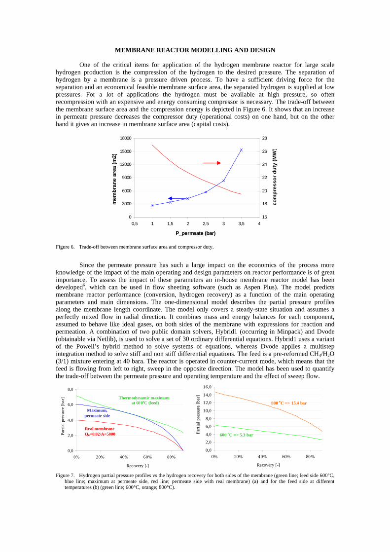
One of the critical items for application of the hydrogen membrane reactor for large scale hydrogen production is the compression of the hydrogen to the desired pressure. The separation of hydrogen by a membrane is a pressure driven process. To have a sufficient driving force for the separation and an economical feasible membrane surface area, the separated hydrogen is supplied at low pressures. For a lot of applications the hydrogen must be available at high pressure, so often recompression with an expensive and energy consuming compressor is necessary. The trade-off between the membrane surface area and the compression energy is depicted in Figure 6. It shows that an increase in permeate pressure decreases the compressor duty (operational costs) on one hand, but on the other hand it gives an increase in membrane surface area (capital costs).
0
3000
6000
9000
12000
15000
18000
0,5 1 1,5 2 2,5 3 3,5 4
P_permeate (bar)
mem
bran
e ar
ea (m
2)
16
18
20
22
24
26
28
com
pres
sor d
uty
(MW
)
Figure 6. Trade-off between membrane surface area and compressor duty.
Since the permeate pressure has such a large impact on the economics of the process more
knowledge of the impact of the main operating and design parameters on reactor performance is of great importance. To assess the impact of these parameters an in-house membrane reactor model has been developed6, which can be used in flow sheeting software (such as Aspen Plus). The model predicts membrane reactor performance (conversion, hydrogen recovery) as a function of the main operating parameters and main dimensions. The one-dimensional model describes the partial pressure profiles along the membrane length coordinate. The model only covers a steady-state situation and assumes a perfectly mixed flow in radial direction. It combines mass and energy balances for each component, assumed to behave like ideal gases, on both sides of the membrane with expressions for reaction and permeation. A combination of two public domain solvers, Hybrid1 (occurring in Minpack) and Dvode (obtainable via Netlib), is used to solve a set of 30 ordinary differential equations. Hybrid1 uses a variant of the Powell’s hybrid method to solve systems of equations, whereas Dvode applies a multistep integration method to solve stiff and non stiff differential equations. The feed is a pre-reformed CH4/H2O (3/1) mixture entering at 40 bara. The reactor is operated in counter-current mode, which means that the feed is flowing from left to right, sweep in the opposite direction. The model has been used to quantify the trade-off between the permeate pressure and operating temperature and the effect of sweep flow.
0,0
2,0
4,0
6,0
8,0
10,0
12,0
14,0
16,0
0% 20% 40% 60% 80%
Recovery [-]
Part
ial p
ress
ure
[bar
]
800 oC => 15.4 bar
600 oC => 5.3 bar
0,0
2,0
4,0
6,0
8,0
0% 20% 40% 60% 80%
Recovery [-]
Part
ial p
ress
ure
[bar
] Thermodynamic maximum at 600oC (feed)
Maximum, permeate side
Real membrane Q0=0.02/A=5000
Figure 7. Hydrogen partial pressure profiles vs the hydrogen recovery for both sides of the membrane (green line; feed side 600°C, blue line; maximum at permeate side, red line; permeate side with real membrane) (a) and for the feed side at different temperatures (b) (green line; 600°C, orange; 800°C).

Figure 7a shows the partial pressure profile of hydrogen at both sides of the membrane in the membrane reformer as a function of the hydrogen recovery at 600°C. It can be seen that there is a maximum hydrogen partial pressure at the permeate side and therefore a maximum permeate pressure to have a sufficient driving force for separation. With a realistic membrane surface area (A) and membrane permeance (Q0) the hydrogen partial pressures/permeate pressure must even be lower than the maximum case. When the temperature increases to 800°C the hydrogen partial pressure on the feed side increases and therefore a higher permeate pressure (15.4 in stead of 5.3 bar) can be used (see Figure 7b). Unfortunately a higher reactor temperature means also an increase in energy and lower system efficiency. The reactor design should therefore be focused on obtaining the highest permeate pressure at the lowest reactor temperature.
CONCLUSION
Palladium membrane reactors have been identified as a promising option for hydrogen production in future power production systems and industrial chemical production processes. For this purpose an R&D programme on the development of palladium membrane reactors hydrogen membrane reactors is being carried out at ECN, which focuses on thinner and cheaper palladium membranes with higher permeation rates, customized catalysts and the design of a feasible large scale membrane reformer.
Dense tubular Pd alloy membranes with a high hydrogen permeance have been made on ceramic supports with electroless plating on a 1m2 scale. Permeation and gas separation measurements have shown that next to scaling-up of the fabrication of thin defect free Pd composite membranes also the sealing between the ceramic tube and the fixation in a metallic tube sheet remains a critical item for the hydrogen membrane reactor development. Two noble metal catalysts, an in-house developed and a commercial catalyst with sufficient stability and activity under membrane reactor conditions were found and selected for application in the membrane reformer. It was shown that methane conversions well beyond the thermodynamic limits could be reached during steam reforming at 650°C and 11 bar in the membrane reformer. A computer model of the palladium membrane reformer was developed and has been used successfully to evaluate the impact of main operating and design parameters on the reactor performance.
ACKNOWLEDGEMENT
The authors gratefully acknowledge the financial support of the Dutch Ministry of Economic Affairs (EZ), EOS and CATO programmes of the work presented.
REFERENCES
1 Jansen, D., P.P.A.C. Pex, J.W. Dijkstra and S.C.A. Kluiters (2004). Membrane reactors: Key technology for production of de-carbonised energy carriers. Proceedings of the 7th conference on greenhouse gas control technologies GHGT-7, September 5-9, Vancouver, Canada.
2 Pex, P.P.A.C., Y.C. van Delft, L.A. Correia, H.M. van Veen, D. Jansen and J.W. Dijkstra (2004). Palladium alloy membranes for energy efficient membrane reactors. Proceedings of the 8th International Conference on Inorganic Membranes ICIM8, USA, July 18-22, Cincinnati, Ohio.
3 Rusting, F., G. de Jong, P.P.A.C. Pex, J.A.J. Peters (2001). Sealing socket and method for arranging a sealing socket to a tube. EP 1128118 [EP 1128118].
4 Pex, P.P.A.C., Y.C. van Delft, L.A. Correia, H.M. van Veen, D. Jansen and J.W. Dijkstra (2004b). Membranes for hydrogen production with CO2 capture. Proceedings of the 7th conference on greenhouse gas control technologies GHGT-7, September 5-9, Vancouver, Canada.
5 van Beurden, P., H.A.J. van Dijk, Y.C. van Delft, J.W. Dijkstra, R.W. van den Brink, P.P.A.C. Pex and D. Jansen (2006). Catalysts for Hydrogen Production in Membrane Reformers. GHGT-8, 8th International Conference on Greenhouse Gas Control Technologies, 19 - 22 June 2006, Trondheim, Norway.
6 van Delft, Y.C. and P.P.A.C. Pex (2003). Membranes for hydrogen production. Proceedings of the 1st European Hydrogen Energy Conference, September 2-5, Grenoble, France.

Energy research Centre of the Netherlands
psp-09-027
ECN P.O. Box 1, 1755 ZG PettenThe NetherlandsE: [email protected]: +31 (0)224 568178
www.ecn.nl
Y.C. van Delft, M. Sarić, D. F. Meyer, A. de Groot
Membrane reformer for large scale production of hydrogen
We gratefully acknowledge our partners for their contribution in this project and the Dutch Ministry
of Economic Affairs for the fi nancial support within the EOS LT programme.
BackgroundThe (petro) chemical industry in the Netherlands is responsible for one sixth
of the total energy use. A substantial part is used to produce industrial
hydrogen. This takes place in huge refor mer units where methane reacts
with steam to become hydrogen and carbon monoxide. One promising new
concept, which maximizes the energy effi ciency of SMR (steam methane re-
forming), is the hydrogen membrane reformer (H2MR).
H2MR is basically a membrane as-
sisted reformer that not only drives
reactions beyond traditional equi-
librium levels but also enables CO2
to be captured under high pressure
in large scale power production
plants.
ObjectiveDevelopment of a H
2MR which delivers 5 Nm3/h hydrogen.
Applications in the Netherlands:
Large scale hydrogen production in the ammonia process •Power generation with integrated CO •
2 capture
Small scale on-site hydrogen supply •Dehydrogenations •
Potential energy savings in NL is 24 PJ/y.
For large scale hydrogen production for the ammonia synthesis, savings can
be 7% compared to the conventional process with an estimated payback
time from 1.3 to 5.7 years.
Hydrogen selective membranesThe critical enabling technology for H
2MR is the hydrogen selective mem-
brane. ECN has developed the technology to apply a very thin layer of Pd
on a ceramic support tube to enable low cost and reliable hydrogen separa-
tion. Currently, membranes can be produced which have a lifetime of several
thousands of hours under different conditions at temperatures up to 450ºC.
Figure 2 Cross section 4-5 μm Pd membrane and 13-tube module
Bench scale MR performanceCH •
4/H
20 = 3, T=530-590°C, Pf=25-42 bara
stable operation for 40 days •max. CH •
4 conversion 98 %
high H •2 single gas permeance (116 m3/m2hbar0.5 at 600ºC)
max. H •2/CH
4 selectivity 1000
Figure 3: Catalyst in annulus arrangement Figure 4 Thermodynamic and measured CH4 conversion
MR modelling1-D isothermal MR model shows good comparison with bench scale MR •experiments.
Figure 5 Comparison CH4 conversion (line –model, dot – experiment)
Future workConfi rm overall performance of new pilot membrane reformer design, •which has large similarities with the standard 5 Nm3/h reformer from
HyGear for on-site hydrogen production.
Validation of available design models. •Study operational aspects (e.g. heat management, start-up/cooling down, •dynamics) for both pilot H
2MR.
Update of technical economic evaluations. •Increase the catalyst and membrane lifetime at high T. •
0 1 0 2 0 3 0 4 0 5 0
2 0
3 0
4 0
5 0
6 0
7 0
8 0
9 0
1 0 0
CH
4 con
vers
ion
[%]
d u ra t io n [d a y s ]
M R e x p th e rm o
Max. increase in CH4 conversion 72 %
Long duration test
Permeate
Sweep
Retentate
Sealing
Reactor
Membrane
Sealing
Mesh
Feed
Support
Quartz frit
Quartz wool
Catalyst
Quartz wool
1 1 0 1 0 00
2 0
4 0
6 0
8 0
1 0 0
CH
4 con
vers
ion
[%]
L /S [m3/m2 h ]
WHSV=0.691 [h-1]
WHSV=0.346 [h-1]
WHSV=0.346 [h-1]
Pf=38 barT=500 ºC
Figure 1: The H2MR concept
reactor shell