membrane distillation and applications for water
TRANSCRIPT

Membrane Distillation and Applications for Water Purification in Thermal Cogeneration- A Pre-study
Chuanfeng Liu and Andrew Martin


Membrane Distillation and Applications for Water Purification in Thermal Cogeneration - A
Prestudy
Membrandestillering och tillampningar for vattenrening i kraftvarmeverk - Forstudie
Chuanfeng Liu and Andrew Martin
M4-401
VARMEFORSK Service AB 101 53 STOCKHOLM ■ Tel 08-677 25 80
Februari 2005ISSN 0282-3772


VARMEFORSK
AbstractThe objective of the present investigation is to explore the feasibility of membrane distillation (MD) as a complimentary or replacement technology for water purification processes in thermal cogeneration plants. This report contains background information on MD, select experimental results, and a case study of industrial applications. Results show that current MD technology features similar energy consumption levels and higher specific costs as compared to reverse osmosis. Prospects for improvement in the near future are judged to be positive regarding these and other aspects.
i


VARMEFORSK
Sammanfattning
Kostnadseffektiv, palitlig och energisnal vattenreningsteknik ar en viktig del i moderna kraftvarmeverk. Avsaltat vatten behovs som spadvatten i fjarrvarmenat samt som processvatten i pannor och turbinanlaggningar. Dessutom har det blivit aktuellt med rening och atervinning av rokgaskondensat. Idag finns det flera lampliga tekniker sasom omvand osmos (RO) och elektroavjonisering (EDI). Membrandestillering (MD) ar en ny lovande teknik i sammanhanget. Denna teknik utnyttjar partialtryckdifferenser for att rena vatten med hjalp av hydrofoba membran. Processen kan drivas av fjarrvarme eller lagtemperaturanga och ar darmed attraktiv i kombination med kraftvarmeproduktion. Denna forstudie fokuseras pa membrandestillering som en ny vattenreningsteknik i kraftvarmeverk. Resultaten kommer att ligga till grund for eventuellt fortsatt forskning som exempelvis kan omfatta pilotstudier. Till malgrupperna hor miljotekniker och driftoperatorer med intresse for ny teknik.
Forstudien omfattar en litteraturstudie, teori gallande mass- och varmetransport samt uppskalning av experimentella resultat. Data fran en testanlaggning som ags av Xzero AB och som finns pa KTH har anvants. Den experimentella renvattenproduktionen lag under den teoretiska maximala grans en vilket visar att det finns potential for forbattringar vad galler MD-modulens design. En fallstudie med ett system som producerar 10 m3 renvatten/h valdes for att belysa kommersiella aspekter. Studien visar att MD ar en lovande alternativ till RO i befintliga eller nya anlaggningar. De basta alternativen ar da varme fran fjarrvarmeframledningen eller lagtemperaturanga (2-3 bar, 200°C) utnyttjas. Det specifika energibehovet for MD ar enligt foljande: 4,0-5,0 kWh varme/m3 producerat renvatten och 1,5-4,0 kWh el/m3 renvatten. Aven om det totala energibehovet ar storre jamfort med RO, kan forbattringar i processen reducera eller eliminera denna nackdel. Elforbrukningen ar huvudsakligen kopplad till MD- anlaggningens hoga interna vattenrecirkulering, som kan minimeras i framtiden. Darmed visar MD tillfredstallande energiprestanda i forhallande till dagens teknik. De specifika kostnaderna ligger kring 10-14 SEK/m3 renvatten for de mest sannolika konfigurationerna. MD:s nuvarande stallning ar darmed nagot svag ekonomiskt jamfort med RO, dock bor man vaga in respektive tekniks utvecklingsgrad i en mer rattvis jamforelse.
Forstudiens lovande resultat motiverar fortsatt forskning. Pilotforsok rekommenderas for att ytterligare utvardera teknikens potential, framforallt nar det galler vattenkvalitet och ekonomi. Grundlaggande undersokningar med mass- och varmetransport i verkliga moduler foreslas, eftersom det finns utrymme for okat utbyte och/eller minskad membranyta. Med fortsatt teknikutveckling och -optimering bor MD kunna utvecklas till en mer konkurrenskraftig teknik.
Nyckelord: membrandestillering; vattenteknik; spadvatten; rokgaskondensat;spillvarme.
iii


VARMEFORSK
SummaryCost-effective, reliable, and energy efficient water treatment systems are an integral part of modern cogeneration facilities. Demineralized water is required for make-up water in district heating networks and in boilers. In addition, increasing attention has been paid to the treatment of flue gas condensate for possible recycling. A number of membrane technologies like reverse osmosis (RO) and electrodeionization (EDI) have been developed for the above applications. Besides these methods, membrane distillation (MD) is promising technology in this context. MD utilizes differences in vapor pressure to purify water via a hydrophobic membrane. The process can utilize district heat supply temperatures or low-grade steam, thus making it attractive for cogeneration applications. This investigation consists of a pre-study to evaluate the viability of membrane distillation as a new water treatment technology in cogeneration plants. Results obtained from the study will be used as an input to follow-on research, which may include the construction of a pilot plant. Target groups for this study include environmental engineers with particular interest in emerging water purification technologies.
Specific elements of this work include a literature survey, theoretical considerations of heat and mass transfer, and scale-up of experimental results. Data obtained from the test facility owned by Xzero AB and located at KTH was employed for this purpose. Actual water production was found to be lower than the theoretical maximum, illustrating the potential for improvements in MD module design. A case study considering a 10 m3 pure water/hr system is explored to shed light on commercial-scale aspects. Results show that MD is a promising alternative to RO in existing or new treatment facilities. The most favorable results were obtained for alternatives where either the district heat supply line or low-grade steam (2-3 bar, 200°C) are available. Specific energy consumption ranges are as follows: 4.0-5.0 kWh/m3 thermal; and 1.5-4.0 kWh/m3 electrical. The relatively high electricity consumption is linked primarily to high recirculation rates versus relative low water production in batch mode. Although the combined energy consumption is higher than RO, future process improvements can be employed to offset or eliminate this disadvantage. MD thus demonstrates satisfactory energy performance compared to existing technologies. Specific costs lie in the range of 10-14 SEK/m3 for the most likely MD system scenarios. These results indicate that MD is presently more expensive than RO, although this comparison should be weighed against the level of development for each respective technology.
These promising results suggest that follow-on research is justified. Pilot plant trials are recommended in order to fully assess the potential of this technology, especially with regards to water quality issues and economic viability. Fundamental investigations considering heat and mass transfer in real membrane modules are also suggested, since there is potential for enhancing pure water production and minimizing membrane area. With continued research and development the possibility of commercializing MD technology in the near-term will become even more likely.
Keywords: membrane distillation; water treatment; make-up water; flue gas condensate; low-grade heat utilization.
v


VARMEFORSK
Table of contents1. INTRODUCTION.......................................................................................................................................1
1.1 Description of the research area....................................................................................................................31.2 The purpose of the research assignment and its role within the research area....................... 3
2. MEMBRANE DISTILLATION WATER PURIFICATION TECHNOLOGY............................... 5
2.1 Background..............................................................................................................................................................52.2 Numerical Model describing AGMD process............................................................................................ 62.3 Experimental study of AGMD.........................................................................................................92.4 Experimental results.......................................................................................................................................... 11
3.INTEGRATED MEMBRANE DISTILLATION WITH THERMAL COGENERATION......... 13
3.1 Introduction: Parameters for case study............................................................................................... 133.2 MD unit connection alternatives................................................................................................................ 15
4. COST ANALYSIS.................................................................................................................................... 20
4.1 Key information and assumptions................................................................................................................. 204.2 Costs, Alternative 1..........................................................................................................................................204.3 Costs, Alternative 2..................................................................................................................... 214.4 Costs, Alternative 3..........................................................................................................................................224.5 Cost calculation results................................................................................................................................. 24
5. CONCLUSIONS AND FUTURE WORK............................................................................................25
6. ACKNOWLEDGEMENT..........................................................................................................................26
vii

VARMEFORSK
Appendices
A WATER QUALITY ANALYSIS REPORT FROM KEMISKA STATIONEN AB
B NON-IDEAL BEHAVIOR OF MD
C HEAT BALANCE AT SITE CONDITION
D LITERATURE REFERENCES
viii

VARMEFORSK
1. Introduction
Thermal cogeneration plants require purified or treated water for a number of processes. The selection of water treatment technology is dependent upon the final water quality along with the volume of water to be treated. A brief overview of current practices is listed below:
Feedwater/make-up water treatment in district heating networks: Water quality should be relatively high in order to avoid corrosion in piping and heat exchangers. Treatment steps include filtration, demineralization (reverse osmosis, ion exchange), deaeration, and pH adjustment via addition of NaOH [1].
Make-up water purification, steam cycle: Metallurgical constraints place a relatively high demand on water quality. A number of processes can be used depending on the particular requirements, including chemical treatment/lime softening, filtration, carbon adsorption, reverse osmosis (RO), and ion exchange resin polishing [2]. The amount of water to be treated depends upon the size of the plant; for example, the Orebro Cogeneration Facility with a fuel capacity of about 500 MW requires 45 000 m3/yr for its boilers [3].
Condensate treatment, flue gas condensation: Wastewater treatment is more complicated and is highly dependent upon the fuel characteristics. The possible presence of heavy metal compounds requires precipitation/flocculation and clarification. Filtration and chemical treatment is required prior to discharge to receiving water [4].
Although the above methods are well established and generally effective, there is still room for improvement regarding availability, economy, and enhanced water purity. Technologies of particular interest include advanced membranes in reverse osmosis (RO) and electrodeionization (EDI) [5].
Beyond these methods, membrane distillation is a promising alternative or complementary technology in water treatment systems of thermal cogeneration facilities. Membrane distillation (MD) is a hybrid process that employs specially designed hydrophobic membranes for the unit operation, and mass transport is driven by differences in vapor pressure [6]. Temperature levels are such that low-grade heat sources (e.g. district heat) may be used to supply the required energy to the process. Unlike other membrane processes, MD does not require high pressures and is not limited by the osmotic pressure. In addition MD differs from other distillation processes in that vacuum pressures and/or high temperatures are not necessarily required.
In short, an MD unit consists of heating and cooling loops connected to a module containing the membranes (which are usually arranged in a series of vertical channels). Raw water is heated and supplied to the hot side, while purified water is collected on the cold side after evaporation through the membrane. Figure 1 shows a schematic diagram of the MD process at the membrane level.
1

VARMEFORSK
Membrane Condensate
Figure 1. Schematic of membrane distillation process, Xzero AB
Water is purified via the following steps [7]:
• Heat is transported from the bulk fluid to the membrane surface, and nonvolatile components diffuse from the membrane surface to the bulk
• Water in the hot containment section evaporates• Water vapor diffuses through the membrane• Water vapor diffuses through the gap, from the membrane surface to the
condensate wall• Water vapor condenses on the condensate wall• Heat is transported through the condensate wall to the coolant
2

VARMEFORSK
Advantages of MD:
• 100% (theoretical) rejection of ions, macromolecules, colloids, cells, and other non-volatiles
• Lower operating temperatures than conventional distillation• Lower operating pressure than conventional pressure-driven membrane
separation processes• Low sensitivity to variations in process variables (e.g. pH and salts [8])• Good to excellent mechanical properties and chemical resistance• Potentially lower capital costs as compared to RO
Disadvantages of MD:
• High energy intensity (although energy, i.e. heat, is usually low grade)• Low yield in non-batch mode; high recirculation rates in batch mode• Sensitive to surfactants• Volatiles cannot be completely separated (degassing or other methods required,
however, volatiles may be captured in the air space which is then vented off)• Not yet commercially available for power plant applications
1.1 Description of the research areaWithin the Varmeforsk framework, water treatment issues have been studied primarily in the context of flue gas condensation [e.g. 10-17]. Here, RO has been the primary focus [10-11]. One ongoing Varmeforsk investigation, Avancerad rening av rokgaskondensat [16] is exploring aspects related to clogging or deterioration of membranes in RO systems. New strategies for pre-treatment are of particular interest, and tests will be conducted in pilot scale equipment. Another Varmeforsk investigation, Ny vattenreningsteknik for energianlaggningar - Det europeiska vattendirektivets praktiska konsekvenser for varmeverken [17] considers new water treatment methods in the context of modified European regulations. Research on MD technologies appears to be a good complement to these studies.
1.2 The purpose of the research assignment and its role within the research area
This investigation is divided into two parts. Part 1 (the present work) consists of a prestudy to evaluate the viability of membrane distillation as a new water treatment technology in thermal cogeneration plants. Specific goals include the following:
• Literature survey of existing and future water treatment technologies in the present context
• Identification of specific applications for cogeneration facilities• Mass and energy balance analysis• Dimensioning of membrane distillation equipment• Economic analysis of installation and operation and maintenance costs
3

VARMEFORSK
Part 2 (to be proposed) will focus on experimental investigations (pilot plant trials) where MD’s performance and applicability for make-up water production is evaluated. Parametric variations for typical raw water and/or flue gas condensate will be considered in detail. Water quality issues are anticipated to comprise a significant element of follow-on work.
4

VARMEFORSK
2. Membrane distillation water purification technology
2.1 BackgroundMembrane distillation (MD) is a novel water purification process being investigated worldwide as a low cost, energy saving alternative to conventional separation processes, such as distillation. The benefits of MD compared to other more popular separation processes are the following: (1) 100% (theoretical) rejection of ions, macromolecules, colloids, cells, and other non-volatiles, (2) lower operating temperatures than conventional distillation, (3) lower operating pressure than conventional pressure-driven membrane separation processes, (4) reduced chemical interaction between membrane mechanical property requirements, and (5) reduced vapor spaces compared to conventional distillation processes [19]. This thermally driven process employs a hydrophobic microporous membrane to support a vapor-liquid interface. If a temperature difference is maintained across the membrane, a vapor pressure difference occurs. As a result, liquid (usually water) evaporates at the hot interface, crosses the membrane in the vapor phase and condenses at the cold side, giving rise to a net transmembrane water flux.
A variety of methods may be employed to impose this vapor pressure difference, and in general there are four kinds of MD system configurations (Figure 2) e. g. direct contact membrane distillation (DCMD), air gap membrane distillation (AGMD), sweep gas membrane distillation (SGMD) and vacuum membrane distillation (VMD).
Liquidtir gapsolution solution
j L
1 '
i L
'
Liquidesolution 0
DCMD AGMD
solution Sweep gas solution Vaccum
i L
'
i i
'
Membrane
SGMD VMD
a) DCMD: The permeate side of the membrane may consist of acondensing fluid in direct contact with the membrane
b) AGMD: A condensing surface separated from the membrane by an air gap (AGMD)
c) SGMD: A condensing surface separated from the membrane by a sweeping gas
d) VMD: Acondensing surface separated from the membrane by a vacuum gap.
Figure 2. Common configurations of membrane distillation [19]
5

VARMEFORSK
DCMD and AGMD are the most popular methods, but one of the problems with DCMD is the relatively low efficiency of heat utilization. A large portion of the heat supplied to the feed solution is lost by conduction through the membrane. Another reason why DCMD is unsuitable for water treatment applications is the need to use pure water for cooling.
In the present work, air gap membrane distillation (AGMD) alone is investigated. The principle advantage of AGMD against other configurations of membrane distillation arises from the possibility of condensing the permeate vapors on a cold surface rather than directly in a cold liquid. In this configuration, the mass transfer steps involve movement within the liquid feed toward the membrane surface, evaporation at the membrane interface and transport of the vapor through the membrane pores and air gap prior to condensation [20].
The most important advantage of the MD process is that it does not need to operate at high temperature as compared to the traditional distillation process, nor are high pressures required as compared to reverse osmosis. Thus low-grade heat (theoretically temperatures in the range from 30 to 70°C) can be employed to drive the MD process. Such temperatures are available from waste heat streams in the power plant or can be obtained from small-scale cogeneration units.
2.2 Numerical Model describing AGMD process
The mathematical model presented by Jonsson et al. [21] is considered for the present study. This model considers one-dimensional, steady state heat and mass transport through a hydrophobic membrane. A summary of this model is given below:
6

VARMEFORSK
membrane Condensing wall
XHot solution
I
Air gap
VaporPore ---------- ►
Coolant
1 b: the thickness of membrane
L: the length of air gap
Figure 3. Schematic representation of the membrane distillation module
As shown in Figure 3. the hot solution flows in the x direction and some mass is lost in the z direction due to evaporation. At steady state the molar flux, TV, of a vapor diffusing through a stagnant air gap is described as [7]:
TV = - CDl-x
(1)
where C is the molar concentration and I) is the diffusion coefficient for the water vapor-air mixture. Although there is a slight effect on the molar flux, the simultaneous mass transfer most directly affects the rate of heat transfer. In this case, the sensible heat, E, includes two terms encompassing conductive and diffusive contributions:
JTE = -t—+Tvc/r-rj (2)
where k is the effective thermal conductivity, Cp is the heat capacity and /', is the absolute temperature of coolant. Differential equations (2) and (3) are solved in the region of membrane and the air gap. The factors C' * 1) and air conductivity Tra;r are obtained according to two empirically derived relations valid for water vapor-air mixtures at around 40°C:
C*D = 6.3*10" Vr (3)
^=i.5*io"Vr (4)
7

VARMEFORSK
The effective thermal conductivity coefficient k for the membrane region is assumed to be obtained from standard porous media relations [22], i.e.
k = kair *^ + kmem&rane (1 -^) (5)
where <f> and kmembrane are the membrane porosity and thermal conductivity. It is possible to obtain explicit expressions for molar and energy fluxes when the above relations are substituted into Equations (4) and (5). Although these expressions have no exact analytical solutions, there are two empirical equations that yield sufficiently accurate values, i.e.:
# = 6.3*10* i n-5 * _ 1 - V*ln(-----^)
& /#*VTj+L/^K 1 - vand
E =1.5*10 -3*(Th - z;)
(b//*^*vzr)+L
. *i+1.4,*in(1zV^)* b/(r*r-El)
1 - V/ , bW}+(L^1
where
1 (6)
(7)
Y =k
^k,(8)
and k and kair should be evaluated at Th. In the above, Vc is mole fraction of water vaporat the condensate surface and Vh is the mole fraction of water vapor at the evaporation surface. The mass flux equation is obtained from the molar flux equation:
Q = 4.1*10-3 *-------- pi-------- ;= * ln(1——)b w*VTi+L/^TT 1 - Vh
(9)
Equation (9) is the formula used in theoretical calculations. In these calculations Th and Tc are the average bulk temperature for hot and cold sides:
Th
T;
T + Th,in h,out
2T' n + T
2
(10)
(11)
8

VARMEFORSK
2.3 Experimental study of AGMD
The MD module being tested in our laboratory was first developed by the Swedish National Development Co. f Statsforetag', now defunct). The company decided to design a membrane distillation plastic cassette for seawater desalination systems and initiate testing under real-life conditions. The cassettes are designed so that they can be stacked together to form modules of varying size. Each cassette consists of injection molded plastic frames containing two parallel membranes, feed and exit channels for the warm water, and two condensing walls. By interconnecting the cassettes, channels for the cooling water are formed between the condensing walls of adjacent cassettes.
This module has been improved to produce ultrapure water suitable for the semiconductor industry (here purity requirements are similar to those for current high pressure boilers and other related equipment). Tests conducted at Sandia National Laboratories in 1998 [28] demonstrated that MD generally performed equally to RO in terms of water quality with a variety of feedstocks (including nonpotable city water). From March 2003 until now, Xzero AB and Department of Energy Technology, KTH have cooperated in running tests with this facility. The current facility is comprised of one membrane module which consists ten cassettes, and the total membrane area is around 2.3 m2 Roughly 10000 h of operation time have been logged with the original equipment (earlier testing was performed in Karlstad). The membrane material is PTFE with a porosity of 80% and thickness of 0.2 pm. The width of air gap of AGMD is 2 mm. The membrane module is made up of nine feed channels and nine permeate channels, and the size of module is 63 cm wide and 73 cm high with a stack thickness of 17.5 cm. A photograph of the membrane module is shown in Figure 4.
Figure 4. AGMD membrane distillation module, Xzero AB (stack thickness is 35 cm in photo)

VARMEFORSK
The experimental flow diagram can be seen in Figure 5. When running the experiment, two taps are used to measure the water flow rate from cold and hot sides. During the experimental period, the pilot plant was operated in three kinds of flow conditions, e.g. 1.36 nri/h, 2.04 m7h, and 2.72 m7h. For simplicity identical flow rates were maintained for both hot and cold streams.
In the pilot plant the feedstock (tap water mixed with table salt) is contained in a 1000 1 tank equipped with three electrical heating elements. Pumps maintain the flow rates to the desired levels. On the cold side, an expansion tank is used to accommodate the expansion of heated cooling water.
Tap water from EGI lab hall is used to cool the cold side through a heat exchanger, so the cold side water is in a closed system. In the summer time, the tap water temperature is very stable and around 25°C, and the cold side temperature can be maintained in the range of 19-25°C. In the hot and cold water pipes and water tank, the temperature of hot/cold water was recorded before entering the MD module, and data is then transferred via a PLC to a computer. The entire experimental setup can be displayed on the computer screen, and the pilot plant is operated by Citect Runtime via PLC connection/control system. With this one can start/shut down and operate the pilot plant easily (remote operation and data acquisition is also possible).
Figure 5. The experimental flow diagram in Pilot plant ofXzero at KTH

VARMEFORSK
2.4 Experimental results
When conducting the experiments, there are several data that are obtained, i.e. pure water production, temperature of cold and hot sides, conductivity of pure water, TDS (total dissolved solids), pH, etc. Measurements related to water quality provide qualitative information as to the expected performance of the unit; more rigorous testing is beyond the scope of this study. TDS is measured with a TDS indicator, pH is measured with pH indicator paper, and pure water conductivity is measured with conductivity sensor. Measurement equipment is shown in Table 1. The pure water production is calculated by timing the volume of water tilling a graduated cylinder.
Parameter Measurement method/equipmentConductivity YOKAGAWA 402TDS HANNA TDS indicatorPH pH test paperHardness Hardness Test Paper
Table 1. Measurement method or equipment in Xzero Test Facility
The measurements are conducted twice per day (three measurements per data type). Recent tests have shown that the conductivity of the pure water produced by the Xzero module is around 1.5 pS/cm at steady state, irregardless of feedstock salt concentration (which ranged from 300-1100 ppm). The pH value of the produced water is around 6.5- 7.0. The TDS value is always under detection limits (4 mg/1). Detailed water analyses were performed in the early 1990's under similar conditions (see Appendix A for these results).
1.36 m3/h (5.0 GPM)
2.04 m3/h (7.5 GPM)
2.72 m3/h (10.0 GPM)
Theoretical results (unadj)
Theoretical results (adj)
Estimated results
0 20 40 60 80 100Hot water temperature (°C)
11

VARMEFORSK
Figure 6 shows a plot of pure water production as a function of hot water temperature for the three internal recirculation flow rates tested. The performance improved at higher flow rates, when the temperature drop in the streamwise direction is lowest. Comparisons to theoretical results are also included. ‘Unadjusted’ theoretical results refer to predictions obtained from the procedure outlined in section 2.2. Significant discrepancies can be seen between this relationship and the experimental data. An attempt was made to modify theoretical predictions by accounting for heat losses and temperature polarization effects (see Appendix B for more details). This prediction, denoted ‘adjusted’ in Figure 10, appears to match experimental values at temperatures under 80°C. However performance is overpredicted at higher temperatures, even with these factors under consideration. Thus a simple linear extrapolation has been employed to predict performance beyond the range of experimental data, up to temperatures of 95°C.
12

VARMEFORSK
3.Integrated membrane distillation with thermal cogeneration
3.1 Introduction: Parameters for case study
In order to illustrate how an MD water purification system could be employed, data from relevant cogeneration facilities has been acquired for a case study. One good example is the Orebro Cogeneration Facility, a biomass-fired unit (wood chips and peat fuels) with an installed capacity of 131 MWe and 325 MWdh [24]. A flue gas condensate unit was installed in 2002. Table 2 shows the characteristics of the condensate. The unit also includes an extensive condensate treatment system that enables the production of purified make-up water from the condensate (hence avoiding the need to purchase raw water). As shown in Figure 7, there are several steps to clean the flue gas condensate, i.e. vibration screen, UF, softening, and RO. The hue gas condensate is first treated by blowing air to drive off carbon dioxide and then is dosed with NaOH to increase pH. The permeate how rate from the RO unit is 20 m7h. and conductivity ranges from 2-5 pS/cm. Aherwards the permeate from RO system proceeds to the ion exchange bed to be purified to meet boiler feed water standards. The boiler make-up water demand is 5-30 nT/h and water quality requirement is shown in Table 3.
Parameter Flue gas condensate characteristicsTemperature (°C) 57-60Flow rate (m3/h) 30PH 3.5Organic content (%) 0.1NH; content (mg/1) 100-200
Table 2. Condensate characteristics in Orebro Power [24]
13

VARMEFORSK
Watertank
Stack gasand then for use as boiler feedwater
Softening
lOOumOC&+air
Reject to stripperNH^ stopper
Lamella Cleaned water to heatingpumps and then to the river ’"Svartan”Lfeavy metal
reduction
Sludge for use
Sydkraft Mala\&me/N3
Figure 7. Flue gas condensate cleaning system [24]
Conductivity (gS/cm) <0.1Silica (gg/1) <5Na (gg/l) <5O, ,gg/l) <5
Table 3. Feed water requirement of high pressure boiler [24]
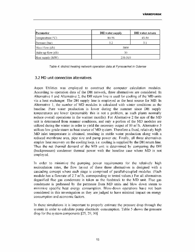
In this system the most logical application of membrane distillation is as an alternative to the RO unit. Assuming that the water quality produced by the MD unit meets or exceeds that obtained from the RO unit, the essential issues of comparison include energy needs and economic aspects related to a system producing 10 nT/h of demineralized water (i.e. one-half the nominal capacity of the Orebro Cogeneration Facility). Predicted MD unit performance is obtained from appropriate scale-up of experimental data for a single module, as outlined in the previous section. The Fynsvserket cogeneration facility in Odense is considered with regards to typical heat sources and sinks for northern European applications. Operation data is listed in Table 4. Operations vary according to the seasonal needs for district heating.
It should be noted that the coolant temperatures considered in this case study are somewhat higher than those tested in the Xzero pilot facility. This has been accounted for via the numerical model presented in the previous section. (MD performance is not very sensitive to cold-side temperatures so long as the dewpoint temperature is maintained.)
14
VARMEFORSK
Parameter DH water supply DH water return
Temperature (°C) 80-96 45-50
Pressure (bar) 3.2 3.1
Mass Flow (t/h) 5800
Make up flow (t/h) 30
Heat supply (MW) 235-310
Table 4: district heating network operation data at Fynsv&rket in Odense
3.2 MD unit connection alternatives
Aspen Utilities was employed to construct the computer calculation modules. According to operation data of the DH network, three alternatives are considered. In Alternative 1 and Alternative 2, the DH return line is used for cooling of the MD units via a heat exchanger. The DH supply line is employed as the heat source for MD. In Alternative 1, the number of MD modules is calculated with winter conditions as the baseline. Pure water production is lower during the summer since DH supply temperatures are lower (presumably this is not a problem, as such plants normally reduce overall operations in the warmer months). For Alternative 2 the size of the MD unit is determined from summer conditions, and only a portion of the MD modules are utilized during the winter in order to yield the necessary output of 10 m3/h. Alternative 3 utilizes low grade steam as heat source of MD system. Therefore a fixed, relatively high MD inlet temperature is obtained, resulting in stable water production along with a reduced membrane area, pipe size and pump power etc. Finally, all three alternatives employ heat recovery on the cooling loop, i.e. cooling is supplied by the DH return line. Thus the net thermal demand of the MD unit is determined by comparing the DH (backpressure) condenser thermal power with the baseline case where MD is not employed.
In order to minimize the pumping power requirements for the relatively high recirculation rates, the flow layout of these three alternatives is designed with a cascading concept where each stage is comprised of parallel-coupled modules. (Each module has a flowrate of 2.7 m3/h, corresponding to tested values.) For all alternatives degasified flue gas condensate is taken as the feedstock to the MD unit. Flue gas condensate is preheated by the permeate from MD units and blow down steam to minimize specific heat energy consumption. Blow-down operations have not been considered in this investigation as they are judged to have minimal impact on energy consumption and economic factors.
In these simulations it is important to properly estimate the pressure drop through the system in order to calculate pump electricity consumption. Table 5 shows the pressure drop for the system components [25, 29, 30].
15

VARMEFORSK
System equipment Pressure drop, barMD module stage 0.1Heat exchanger 0.08Piping 0.04Valve and other components 0.1Total pressure drop 0.32
Table 5: Pressure drop of system components
Alternative 1. Fixed MD modules variable pure water production
The details of this alternative are shown in Figure 8. A total of 10 cascading stages have been selected for this design, where each stage contains around 30 modules. Winter operation has been selected as the design condition for determining the number of modules required for the desired production of 10 nT/h.
Concentrate blowdown
Make up water ME 1
MD 1-10: MD stage numberPH: Hot side pumpPC: cold side pumpHE: Hot side heat exchangerCE: Cold side heat exchangerME: make-up water heat exchanger
—► Pure water
Figure 8. Connection of fixed number of MD units with DH network
Simulation results are shown in Table 6, and detailed heat/mass balance results are contained in Appendix C.
16

VARMEFORSK
Parameter Winter case Summer case
DH temperature (°C) 97 81MD hot side temperature (°C) 91 76MD cold side temperature (°C) 55 50Water output (m3/h) 10.1 5.2Specific thennal energy consumption (kWh/m3) 4.0 4.0Pumping power (kW) 20 19
Specific electricity consumption (kWh/m3) 2.0 1.9Membrane area (nr) 828 828
Table 6: Simulation results of Alternative 1
Alternative 2. Variable MD modules with variable pure water production
This configuration resembles Alternative 1, however the size of the MD unit is determined from summer conditions, and only a portion of the MD modules are utilized during the winter in order to yield the necessary output of 10 nT/h. Data contained in Table 7 show that the total membrane area increases by about 100 % given these conditions.
Parameter Winter case Summer case
DH temperature (°C) 97 81MD hot side inlet temperature (°C) 91 76MD cold side inlet temperature (°C) 55 50
Water output (m3/h) 10.1 10.1Specific thennal energy consumption
(kWh/m3) 4.0 4.0
Pumping power (kW) 20 40
Specific electricity consumption (kWh/m3) 2.0 4.0
Membrane area (m2) 828 1656
Table 7: Simulation results of Alternative 2
Alternative 3, Low grade steam utilization
Since MD unit performance increases linearly with temperature, it is of interest to explore an option utilizing a higher temperature source to study the influence on membrane area. Here, low grade steam (2-3 bar, 200°C) is assumed to be available in sufficient quantities to provide heat at a level of 95°C. Figure 9 shows the layout of this alternative. The steam is supplied to an auxiliary heater, and condensate is returned to the condenser.
17

VARMEFORSK
Figure 9. Connection of fixed number of MD units with an auxiliary heater
As shown in Table 8, the benefits of utilizing low grade steam include a significant reduction in membrane area as well as lowered pumping power. These gains must be weighed against the added cost and complexity of a new steam line.
Items Winter case Summer case
MD hot side inlet temperature (°C) 95 95MD cold side inlet temperature (°C) 55 50
Water output (m3/h) 10 10Specific thermal energy consumption
(kWh/m3) 5.0 5.0
Pumping power (kW) 15 15Specific electricity consumption
(kWh/m3) 1.5 1.5
Membrane area ( m2) 660 660
Table 8: Simulation results with auxiliary heater (Alternative 3)
18

VARMEFORSK
Comparison of Specific Energy Consumption
The above results show the trade-off between thermal energy and electricity as the source temperature is raised. Clearly the size of the MD unit is large as the hot-side temperature is reduced, and this is especially apparent in comparing Alternative 2 to the other options. As indicated previously, the thermal energy demand is computed from the difference in DH condenser thermal power with and without an MD unit. While heat recovery is assumed on the cooling loop, the possibility of including the permeate in a broader energy balance has not been considered. Hence the specific thermal energy consumption may actually be lower than reported. Electricity demand is linked to relatively high hot-side and cold-side recirculation rates, each roughly one order of magnitude higher than the pure water production rate. However, Alternatives 1 and 2 show specific electricity values roughly at the same level for comparable RO systems. Recirculation rates can be reduced further by a combination of optimized process layout as well as improved MD module design (this would also have an impact on thermal requirements and cost). Hence it is fair to say that the cases studied herein suggest that membrane distillation demonstrates satisfactory energy performance given the fact that the technology is not fully commercialized.
19

VARMEFORSK
4. Cost analysis
4.1 Key information and assumptions
The following economic analysis considers the capital and operating costs directly related to the membrane distillation unit, including all necessary connections. Costs related to pretreatment equipment have not been included. The following information and assumptions have been employed [25]:
• Cogeneration facility operated 8000 h/yr.• Demineralized water production is 10 nT/h (nominally).• Heat sources/sinks are described in previous chapter.• The net present value and internal rate of return is 7 %.• Membrane lifetime is 5 yr, other equipment lifetime is 15 yr.• Combined unforeseen expenses (i.e. margin of safety) and gross profit is 50%.• The annual maintenance cost is 5% of the installed cost.• Membrane price is 290 SEK/m2• Electricity price is 0.5 SEK/kWh, and heat energy price is 0.4 SEK/kWh (taxes
excluded).• Construction price is 350 SEK/hour.• Cost of control system for MD unit is 90 000 SEK• The lifetime of steam line in Alternative 3 is 20 years.• System heat losses are 5%.• Required steam flow rate (5-10 kg/s) does not significantly impact plant
operations.• Costs related to increased space demands not included. (Alternatives 1 and 2
require about 300 m2 of additional space, while Alternative 3 requires an additional 200 m2)
• Variable cost includes membrane removal and replacement at five year intervals.
4.2 Costs, Alternative 1
Table 9 contains a summary of the major costs associated with this alternative. Some comments on this information: •
• 'MD modules cost' represents the cost to construct the MD module, excluding membranes.
• The main water pipes in hot and cold sides are DN-150.• Control system purchased from Citect and includes necessary programming.• 'Others' includes a level switch valve.• Construction costs obtained from Carl or AB [25].
20

VARMEFORSK
Item Quantity Unit Cost Net Cost (MSEK)Membrane 828 m2 290 SEK/m2 0.24
MD modules 360 5000 SEK 1.8Heat Exchangers PH1 10 40000 SEK 0.4Heat Exchangers PH2 10 30000 SEK 0.3Pump 20 30000 0.6Water tank 1 20000 0.02
Piping 500 m 600 SEK/m 0.3Valves 100 2000 0.2Temperature Indicators 25 2300 0.06Pressure indicators 20 2800 0.06
Security system 4 5000 0.02Control system 0.02Construction 800 h 350 SEK/h 0.28Others 0.3Subtotal 4.650% margin of error/profit 2.3Total investment 6.9
Table 9. Investment table of Alternative 1
Annual costs are summarized in Table 10.
Item Quantity Unit CostNet cost (MSEK)
Pump electricity160 MWh 500 SEK/MWh
0.08
Heat energy 336 MWh 400 SEK/MWh 0.13Maintenance cost 0.05Variable cost 0.07
Total annual cost 0.33
Table 10. Annual cost of Alternative 1
4.3 Costs, Alternative 2
21

VARMEFORSK
Table 11 contains a summary of the major costs associated with this alternative, and annual costs are listed in Table 12.
Item Quantity Unit CostNet Cost (MSEK)
Membrane 1656 m2 290 SEK/m2 0.48
MD modules 600 5000 SEK 3.0Heat Exchangers PH1 10 60000 SEK 0.6Heat Exchangers PH2 10 50000 SEK 0.5Pump 20 40000 0.8Water tank 1 20000 0.03
Piping 500 m 600 SEK/m 0.3Valves 100 2000 0.2Temperature Indicators 25 2300 0.06Pressure indicators 20 2800 0.06
Security system 4 5000 0.02Control system 0.02Construction 800 h 350 SEK/h 0.28Others 0.3Subtotal 6.6550% margin of error/profit 3.37Total investment 9.98
Table 11. Investment table of Alternative 2
Item Quantity Unit CostNet cost (MSEK)
Pump electricity200 MWh 500 SEK/MWh
0.1
Heat energy 336 MWh 400 SEK/MWh 0.13Maintenance cost 0.06
Variable cost 0.11
Total annual cost 0.4
Table 12. Annual cost table of Alternative 2
4.4 Costs, Alternative 3
Table 13 contains a summary of the major costs associated with this alternative. Some comments on this information:
22

VARMEFORSK
• A steam line is used to heat the hot-side feedstock up to 95 °C.• Steam parameters: Pressure 2-3 bar, Temperature 200 °C, Flow rate: 5-10 kg/s.• Condensed steam leads to condenser (i.e. heat is recovered).• The steam line cost includes control system.• Steam line price obtained from Swedpower AB[26].
Item Quantity Unit Cost Net Cost (MSEK)Membrane 660 m2 290 SEK/m2 0.2
MD module 287 5000 1.4Steam line including control system 100m 1.0Heat Exchangers PH1 10 20000 SEK 0.2Heat Exchangers PH2 10 20000 SEK 0.2Pump 20 12000 SEK 0.24
Water tank 1 20000 0.02Piping 400 m 500 SEK/m 0.2Valves 50 2000 0.1
Temperature indicators 10 2300 0.02Pressure indicators 10 2800 0.03Others 0.45Security system 4 5000 0.02Control system 0.03Construction 600 h 350 SEK/h 0.21Subtotal 4.3250% margin of error/profit 2.16Total investment 6.48
Table 13: Investment table of Alternative 3
Annual costs are summarized in Table 14.
Item Quantity Unit Cost Net cost (MSEK)
Pump electricity120 MWh 500 SEK/MWh
0.06
Heat energy 420 MWh 400 SEK/MWh 0.17Steam line Maintenance cost 0.03
Maintenance cost 0.04
Variable cost 0.05
Total annual cost 0.35
Table 14: Annual cost table of Alternative 3
23

VARMEFORSK
4.5 Cost calculation results
The capital costs of purified water production can be estimated based on the above data (fifteen-year operational span), and these results are summarized in Table 15. Utilizing the higher temperature heat source shows the best performance, even if the cost to install a steam line is included. At present the specific water cost for an RO system with same capacity is around 4 SEK/m3 [27]. All estimates compare fairly well to reverse osmosis systems, especially if one considers the potential for technology improvement with this young technology.
Specific water costs, low end estimate
(SEK/m3)
Specific water costs, high end estimate including 50%
uncertainty/profit (SEK/m3)Alternative 1 10 14Alternative 2 14 19Alternative 3 10 12
Table 15. Specific capital cost comparison of the three alternatives
24

VARMEFORSK
5. Conclusions and future work
This investigation shows that membrane distillation is a promising technology for demineralized water production in thermal cogeneration plants. Experimental trials conducted to date indicate that this technology meets minimum requirements regarding proof-of-concept and water quality. Data obtained from relevant experimental trials was scaled up to illustrate the performance of a 10 m3/h unit supplied with heat either from the district heat supply line or low-grade steam. Heat and mass balance calculations show that the specific thermal and electricity demands lie around 4.0-5.0 kWh/m3 and 1.5-4.0 kWh/m3, respectively. Although the combined energy consumption is higher than reverse osmosis, the ability to recover heat coupled to expected improvements in process and component design make MD a competitive alternative. Economic estimates place the cost of demineralized water production in the range of 10-14 SEK/m3 for the most likely scenarios; this level lies above RO but is nonetheless positive given the early stage of development of MD technology.
These results suggest that follow-on studies are of merit, especially for applications where the raw water quality is much lower than that studied in the present investigation. Desalination is clearly one promising area that deserves more attention. For cogeneration applications, the construction and testing of a pilot plant with a capacity of at least 1 m3/h is suggested. Pilot plant trials will allow for a more detailed evaluation of this technology under actual operating conditions (especially at higher temperature levels which could not be tested in the present experimental facility). Specific aspects related to water quality issues and long-term performance, which were largely beyond the scope of the present investigation, can be readily addressed in these tests. Options for commercialization, including more detailed economic analyses, should also be considered. Finally there is a clear need to conduct in-depth fundamental heat and mass transfer studies on actual membrane modules in order to further optimize the process.
25

vArmeforsk
6. Acknowledgement
This research was sponsored by Varmeforsk AB. The authors wish to thank all members of the reference group - Mats Westermark, Barbara Goldschmidt, Jinying Yan, Karol Daucik, and Jorgen Peter Jensen - for their guidance and assistance in this project. Aapo Saask and Henrik Dolfe (Xzero AB) are thanked for their help in supplying important cost data as well as cooperation with their test facility. Per Almqvist and Torsten Fransson (KTH) provided valuable comments on the manuscript. Finally, Carl-Uno Lindin (Sydkraft Malarvarme AB) is thanked for hosting a visit to the Orebro Cogeneration Facility.
26

VARMEFORSK
Appendices
A Water quality analysis report from KeMiska Stationen AB, Dated April 4,1991
JAMFORELSE AV ANALYSRESULTAT
PARAMETER KRANVATTEN RENAT VATTEN TJANLIGT FRAN VATTENVERK
FARG 5 <5 <15 I
TURBIDITET 0.4 0.2 <0.5
LUKT INGEN TYDLIG INGEN
B0TTEN5ATS INGEN INGEN INGEN
KONDUKTIVITET 16.2 0.6 SAKNAS VARDE
COD-Mn 2 <1 <4
_________________ 7.8 7.2 7.5 - 9.0
AMMONIUM-N <0.1 <0.1 <0.4
totalhArdhet 3.9 0 <15
KALCIUM 25 0 20 - 60
MAGNESIUM 1.9 0 <30
NATRIUM 9.2 0.07 <100
KALIUM 2.3 0.5 <20
JARN <0.05 <0.05 <0.10
MANGAN <0.02 <0.02 <0.05
ALKALINITET 50 1 >60
KLORID 11 0.3 <100
FLUORID 0.2 <0.1 0.8 - 1.2
SULFAT 39 <1 <100
NITRAT-N <0.5 <0.5 <5
NITRIT-N 0.003 0.002 <0.005
FOSFAT-P <0.05 <0.05 <0.20
ALUMINIUM 0.04 0.03 <0.10
HOPPAR <0.02 <0.02 <0.05I
1

VARMEFORSK
JAMFORELSE AV ANALYSRESULTAT
PARAMETER SALTVATTENRAVATTEN
1RENAT VATTEN TJANLIGT FRAN
VATTENVERK
FARG 15 5 <15
TURBIDITET 1.4 0.7 | <0.5
LUKT INGEN BRANT INGEN
BOTTENSATS SPAR INGEN INGEN
KONDUKTIVITET 281 7.8 SAKNAS VARDE
COD-Mn 6 (74) <4
pH 7.8 4.6 7.5 - 9.0
AMMQNIUM-N <0.1 <0.1 <0.4
totalhArdhet 22.4 0.4 <15
KALCIUM 44 1.9 20 - 60
MAGNESIUM 70 0.7 <30
NATRIUM 500 2.8 <100
KALIUM 27 0.3 <20
JARN <0.05 <0.05 <0.10
MANGAM <0.02 <0.02 <0.05
ALKALINITET 69 0 >60
klorid 970 9 <100
FLUORID 0.3 <0.1 0.8 - 1.2
SULFAT 165 <1 <100
NITRAT-N 0.6 <0.5 <5
NITRIT-N 0.006 0.005 <0.005
FOSFAT-P <0.05 <0.05 <0.20
ALUMINIUM 0.12 <0.02 <0.10
KOPPAR <0.02 0.03 <0.05
2

VARMEFORSK
JAMFORELSE AV ANALYSRESULTAT
PARAMETER SOTVATTENrAvatten
RENAT VATTEN TJANLIGT FRAN VATTENVERJK
FARG 30 10 <15
TURBIDITET 13 0.5 <0.5
LUKT SVAG OBEST BRANT INGEN
BOTTEHSATS TAML STOR INGEN INGEN
KONDUKTIVITET 34.6 4 . 5 SAKNAS VARDE
COD-Mn 12 (12) <4
PH 8.5 7.7 7.5 - 9.0
AMMOHIUM-N <0.1 <0.1 <0.4
totalhArdhet 6.9 0.4 <15
KALCIUM 38 2.0 20 - 60
MAGNESIUM 7.0 0.4 <30
NATRIUM .14 4,6 <100
KALIUM 4.3 0.5 <20
JARN 0.22 <0 - 05 <0.10
MANGAN 0.08 0.03 <0.05
ALKALINITET 111 8 >60
KLORID 62 9 <100
FLUORIC 0.3 <0.1 0.8 - 1.2
SULFAT 41 <1 <100
NITRAT-N <0.5 <0.5 <5
NITRIT-N 0.010 <0.002 <0.005
FOSFAT-P <0.05 <0.05 <0.20
ALUMINIUM 0.09 <0.02 <0.10
KOPPAR <0.02 <0.02 <0.05
3

VARMEFORSK
B Non-ideal behavior of MDThere are three major heat and mass transfer inefficiencies in MD, i.e. temperature polarization across the membrane, mass transfer resistance to vapor flow through the membrane due to the presence of trapped air in the pores, and conductive heat losses through the membrane [19]. More information on these losses are provided below, and other details can be found in Chuangfeng [31]:
B.1 Temperature polarization effectsHeat is transferred across the membrane through two primary pathways: latent heat of evaporation, together with convective transport in vapor phase, and conduction heat transfer through the membrane. Thermal boundary layers develop as a result of these resistances, ultimately limiting mass transfer [32]. One way to quantify these effects is via the so-called temperature polarization coefficient, TPC [32]:
TPC =T - TA m1 A m2
T - T1b\ 1 b 2
(1)
where Tmi is the interfacial feed temperature, Tm2 the interfacial permeate temperature, TbI the bulk feed temperature, and Tb2 is the bulk permeate temperature. This value represents the ratio of the actual driving force to the overall driving force. A schematic drawing of temperature polarization in MD is shown in Figure A1. Since the evaporation and condensation rates depend on the interfacial temperatures (not the bulk temperatures), and because the partial vapor pressure driving force is mainly a function of temperature, it is desired that the difference between Tm1 and Tm2 should be as high
as possible [33]. In other words, the TPC should be as close to unity as possible. However, in practice, the TPC value is lower than unity and varies between 0.2 and0.9[34], depending on the membrane module configuration. Results from Phattaranawik et al. [35] show that a TPC of about 0.4 is suitable for the present case (PTFE membrane, thickness of 0.2 pm). Higher coefficients are possible via enhanced turbulence [36], although tradeoffs with pressure drop and reduced surface areas must be properly accounted for.
4

VARMEFORSK
Vapour flowAir Gap
Condensate wall
Temperature
Coolant
Solute
VapourPressure
MembraneFigure At. Profile diagram of air gap membrane distillation
B.2 Resistance to mass transfer through the membrane in MD
Vapor transported through membrane pores encounter resistance from trapped air/gases and via the tortuosity of the pore structure [38]. Several approaches to overcome these resistances have been studied in the last twenty years. In the early 1980s, Schneider and van Gassel (1984) introduced the idea of degasification of the working fluids in DCMD systems to reduce the partial pressure of air in the membrane pores. Membrane properties such as porosity, pore size, tortuosity, and membrane thickness are most important factors to dictate the resistance to mass transfer through micorpores in MD [36]. Furthermore, studies have shown that the relationships between the membrane properties (not only the properties by themselves) as well as membrane conditions (e g., compaction, wetting, etc.) are important for efficient operation. Therefore, selection of an appropriate membrane that poses the least resistance to mass transfer is crucial.
5

VARMEFORSK
B.3 Conductive heat loss through the membrane
It is impossible to completely control the conductive heat loss through the membrane because of the tradeoff between a thick membrane for better heat insulation and a thin membrane for reduced mass flow resistance in the membrane [34]. One possible solution is to increase the porosity of the membrane, since the air in the pores of membrane has better insulation properties than the polymeric material of the membrane. (Increased porosity also increases the available surface area for evaporation.) However, microporous membranes with porosities of 80% and even higher already exist, and further improvement may only be achieved when nanotubetechnology matures [39]. Alternative materials for membrane are also not expected to improve the process because of the strict requirement for hydrophobicity and relatively similar heat conductivities of most hydrophobic polymers [40].
4
Coolant
3
____1
3---->__
2
Hot Solution
1. Distillate channel2. Membrane3. Ridges4. Condensing wall
Figure A2. The ridge arrangement
Module construction also plays an important role in conductive losses. As illustrated in Figure A2, ridges used to support the membrane offer a pathway for heat transfer and block a portion of the membrane surface area for mass transfer. The latter was accounted for by an effective area coefficient, 4c//. defined as the unblocked membrane area divided by the actual membrane area. A value of Aeff = 0.9 was assumed for the present study.
6

VARMEFORSK
C Heat balance at site condition
C.1 Alternative 1
District heating water
DH water inlet temperature DH water mass flow DH water inlet pressure DH water temperature after CE (1-10)DH water temperature before condenser DH water temperature after condenser DH water temperature after HE (1-10)DH water pressure
MD unit characteristics
Hot side water inlet temperature per stageHot side water outlet temperature per stageHot side water pressureCold side water inlet temperature per stageCold side water outlet temperature per stageMD process water flow rateHot side heat demand per stageCold side heat recovered per stage
Permeate flow rateNet thermal power delivered by DHcondenser*Pump power Membrane area
Winter case Summer case
°C 50 45m3/h 5800 5800bar 3.2 3.2°C 51 46°C 51 46°C 97 81°C 96 80bar 3.3 3.3
°C 91.0 76.0°C 84.0 71.0bar 1.34 1.34°C 55 50°C 60 55kg/s 22 22kW 656 369kW 644 366
m3/h 10.1 5.1
kW 40 20
kW 20 19m2 880 880
*as compared to baseline case without MD unit
7

vArmeforsk
C.2 Alternative 2
District heating waterWinter case
DH water inlet temperature °C 50DH water mass flow m3/h 5800DH water inlet pressure bar 3.2DH water temperature after CE (1-10) °C 51DH water temperature before condenser °C 51DH water temperature after condenser °C 97DH water temperature after HE (1-10) °C 96DH water pressure bar 3.3
MD unit characteristics
Hot side water inlet temperature per stage °C 91.0Hot side water outlet temperature per stage °C 84.0Hot side water pressure bar 1.34Cold side water inlet temperature per stage °C 55Cold side water outlet temperature per stage °C 60MD process water flow rate kg/s 22Hot side heat demand per stage kW 656Cold side heat recovered per stage kW 644
Permeate flow rate m3/h 10.1Net thermal power delivered by DH condenser* kW 40
Pump power kW 20Membrane area
*as compared to baseline case without MD
m2 880
unit
Summer case
4558003.246 46 80.5 803.3
76.071.0 1.34 50 55 44 643 640
10.1
40
401656
8

VARMEFORSK
C.3 Alternative 3
District heating water
DH water inlet temperature DH water mass flow DH water inlet pressure DH water temperature after CE (1-10)DH water temperature before condenser DH water temperature after condenser DH water pressure
MD unit characteristics
Hot side water temperature inletHot side water temperature outletHot side water pressureCold side water inlet temperature per stageCold side water outlet temperature per stageMD process water flow rateHot side heat demand per stageCold side heat recovered per stage
Permeate flow rateNet thermal power delivered by DHcondenser*Pump power Membrane area
Winter time Summer time
°C 50 45m3/h 5800 5800bar 3.2 3.2°C 51 21°C 51 21°C 96 81bar 3.3 3.3
°C 95 95°C 86 86bar 1.34 1.34°C 55 50°C 60 55kg/s 18 18kW 841 836kW 828 830
m3/h 10 10
kW 50 50
kW 15 15m2 660 660
*as compared to baseline case without MD unit
9

VARMEFORSK
D Literature references
[1] A review of European and North American water treatment practices, 1996 N8.[2] RE-129 Advanced water treatment for the power generation Industry, Business
communications company, Inc., December 15, 2003.[3] Personal communication. Fredrik Axby, Carl Bro Energikonsult AB, February 25,
2004.[4] The Spittelau thermal waste treatment plant, Ing. Willibald Stern, Dr. Philipp
Krobath.[5] Feed Water Treatment for Industrial Boilers & Power plants, New Logic Research
Inc, June 2003.[6] M. Celere, C. Gostoli, The heat and mass transfer phenomena in somotic
membrane distillation, Journal of Desalination, 147(2002) 133-138.[7] A. S. Jonsson, R. Wimmersted and A.C. Harrysson, Membrane Distillation- A
Theoretical Study of Evaporation Through Microporous Membranes, Desalination, 56 (1985) 237-249.
[8] L. Martinez, F. G. Florido-Diaz, Theoretical and experimental studies on desalination using membrane distillation, Desalination 139 (2001) 373-379.
[9] K. Schneider and T. J. Van Gassel, Chem. Ing. Tech, No 7, 56 (1984) 514-521[10] Barbara Goldschmidt, ‘Nyttiggorande av Kondensat fran rokgaskondensering’,
Varmefrosk rapport 568 (1996).[11] Fredrik Axby, ’Avsaltning av varmet rokgaskondensat med membranteknik’,
varemeforsk rapport 643 (1998).[12] Fredrik Axby, Jan-Olof Gustafsson, Johan Nystrom, och Kent Johansson, ‘Studie
av rokgaskondensering for biobransleeldade kraftvaremeanlaggningar ’,Varmeforsk rapport 719 (2001).
[13] Lena Sundquist, Charlotte Dejfors, och Lars Wrangensten, ’Rening av kondensat fran rokgaskondenseringsanlaggningar vid samforbranning av avfallsbranslen. Uppfoljning av utslapp’, Varmefrosk rapport 767 (2002).
[14] Fredrik Axby, ’Rokgaskondensering; Fordelning av emissioner melland gas och kondensat’, Varmefrosk rapport 792 (2002).
[15] Barbara Goldschmidt och Magnus Nordling, ’Materialva vid rokgaskondensering’ Varmeforsk rapport 800 (2003).
[16] Varmeforsk ongoing project, M4-302, ’Avancerad rening av rokgaskondesat’,Carl Bro Energikonsult.
[17] Varmeforsk ongoing project, M4-324 , ’Ny vattenreningsteknik for energianlaggningar-Det europeiska vattendirektivets praktiska konsekvenser’,Carl Bro Energikonsult.
[18] Dr. Jie Zhang, Study Notes for CPE 214- Process Services, Part 4. Boiler Feed water Treatment.
10

VARMEFORSK
[19] Kevin W. Lawson, Douglas R. Lloyd, Review of Membrane Distillation, Journal of Membrane Science, 1997.
[20] S. Bouguecha, R. Chouikh et al, Numerical study of the coupled heat and mass transfer in membrane distillation, Magazine of Desalination.
[21] A.-S. Jonsson, R. Wimmerstedt, A.-C. Harrysson, Membrane Distillation - A Theoretical Study of Evaporation through microporous membrane, Desalination,56 (1985) 237-249.
[22] A. Bejan, Convective Heat Transfer, 2nd edition, Wiley, 1995[23] Power plant operation data in Orebro, Sydkraft AB.[24] Personal communication. Carl-Uno Lindin, Sydkraft AB.[25] Personal communication. Henrik Dolfe, Xzero AB, Stockholm.[26] Personal communication. Jonas Forsman, Swedpower AB, Sweden[27] E8 series Reverse Osmosis Machine Spec Sheet, GE Water & Process
Technology, 2002.[28] R.P. Donovan and D. J. Morrison, Evaluation of membrane distillation(MDU)
prototypes for use in semiconductor manufacturing, Sandia National laboratories (1998).
[29] Personal communication. Maria Eriksson, Tranter PHE AB, Sweden.[30] Pipe pressure drop calculator, http://www.carf-engineering.com/.[31] Chuanfeng Liu, Poly generation of Electricity, Heat and Ultra pure water for
Semiconductor Industry, Master thesis report, Department of Energy Technology, Royal Institute of Technology, Sweden, 2004.
[32] G.C. Starti, C. Gostoli, S. Matuli, Low energy cost desalination process using hydrophobic membranes, Desalination 56 (1985), 277.
[33] Tzahi Y, Cath, V. Dean Adams, Amy E. Childress, 2004.[34] Burgoyne, M. M. Vahdati, Direct contact membrane distillation-review, sep. Sci
Technology, 35 (2000) 1257.[35] J. Phattaranawik, R, Jiraratananon, A. G. Fane, Heat transport and membrane
distillaiton coefficients in direct contact membrane distillation, Journal of Membrane Science 212 (2003) 177-193.
[36] K. W. Lawson, D. R. Lloyd, Membrane distillation, Module design and performance evaluation using vacuum membrane distillation, J. Membr. Sci. 120 (1996) 111.
[37] L. Martinez- Diez, M.I. Vazquez-Gonzalez, Study of membrane distillation using channel spaces, J. Membra. Sci. 144(1998) 45.
[38] A.G. Fane, R.W. Schofield, Cj.D. Fell, the efficient use of energy in membrane distillation, Desalination 64 (1987) 231.
[39] S.B. Sinnott, Computational Studies of Carbon Nanotube-based membranes and New Materials Eighth Foresight Conference on Molecular Nanotechnology, Bethesda, Maryland, 3-5 November 2000.
[40] Maksym N. Chernyshov, G. Wytze Meinderma, Andre B. de Haan, Modelling temperature and salt concentration distribution in membrane distillation feed channel, Desalination 157 (2003) 315-324.
11

vArmeforsk
12

VARMEFORSK
Varmeforsk AB 101 53 Stockholm
29 October 2004
STATEMENT ON QUALITY ASSURANCE
The undersigned hereby certifies that the report 'Membrane Distillation and Applications for Water Purification in Thermal Cogeneration - A Prestudy' meets generally accepted quality guidelines for engineering research. These guidelines have been checked within the framework of an internal review process conducted by Tekn. Lie. Per Almqvist and the undersigned.
Prof. Torsten H. Fransson Director, KTH Energy Center
KTH - Stockholm. Energicenter, Brinellv. 60. SE-100 44 Stockholm, Sweden tel +46(8) 790 74 75, fax +46(8) 20 41 61, e-mail: ftansson@enetgy klh.se
13

RAPPORTFORTECKNINGForteckning over tidigare publicerade rapporter, kan bestallas hos Varmeforsk.Telefax: 08-677 25 35Telefon: 08-677 27 54 http://www.varmeforsk.seSiffrorna mom parentes anger forskmngsgrupp/program:
1 = Material- och kemiteknik2 = Miljo- och forbranningsteknik3 = Anlaggningsteknik6 = Tillampad forbranningsteknik
844 Forbranningsfbrhallanden vid omblandning i branslebaddar pa rorlig rost vid eldning av biobransle och sameldning med naturbranslen - etapp 1; Fbrsok i en kail anlaggningJurgen Jacoby, Asa Rodin november 2003 E2-003 (6)
845 Robust instrumentering Anders Wikdecember 2003 M9-829 (1)
846 Avvattning av aska franblandbranslen;Erfarenheter och resultat fran Tekninska Verken i Linkoping Ulf Carlsson, Anders Fredriksson, Inge Lindahl, Anna Arevius, Rolf Sjoblom december 2003 A9-835 (3)
847 Lagtemperaturkorrosion i pannor med SNCRBarbara Goldschmidtjanuari 2004 M4-218 (1)
848 Anvandning av energiaskor som fillermaterial vid betongtillverkning Hillevi Sundblomjanuari 2004 Q4-219 (10)
849 Forutsattningar for att askor kommer till anvandning i vagarErik Karrman, Denis Van Moeddaert, Henrik Bjurstrom, Magnus Berg, Bo Svedbergjanuari 2004 Q4-207 (10)
7 = Torkning av biobransle8 = Skogsindustriella programme!9 = Processtyming10= Miljoriktig anvandning av askor
850 Roterugn for bedomning av sintringbenagenhetJenny Larfeldt, Frank Zintl januari 2004 F4-208 (2)
851 Rening av baddmaterialFrank Zintl, Birgitta Stromberg, Jenny Larfeldt, Henrik Broden, Peter Sjovall januari 2004 F4-217 (2)
852 Pannsand som fillermaterial forfj arrvarmerorgravarRoger Pettersson, Pascal Suer, Jan Rogbeckjanuari 2004 Q4-220 (10)
853 Energieffektivisering av anlaggningar for stoftrening med slangfilterLars Eriksson, Karin Wikman, Magnus Bergjanuari 2004 A4-310 (3)
854 Experimentell studie av inverkan av trapulvers storleksfordelning pa forbranningsegenskaper Christian Fredrikssonjanuari 2004 F4-211 (2)
855 Askor och rotslam som tackskikt for gruvavfallMattias Backstrom, Inger Johansson januari 2004 Q4-146 (10)
856 En forenklad testmetodik for kvalitetssakring - etapp 1Henrik Bjurstrom, Magnus Berg, Maria Aim, Pascal Suer, Karsten Hakansson januari 2004 Q4-148 (10)
857 Databas inom delprogrammet ”Miljoriktig anvandning av askor”Henrik Bjurstrom, Camilla Rydstrand, Magnus Berg, Karin Wikman januari 2004 Q4-211 (10)
858 Naturliga koldmedierFramtida varmepumpar for fjarrvarme Paul Ingvarsson, Ingela Steen Ronnermark, Marcus Eriksson januari 2004 A4-303 (3)
859 Kvavgasbubbling i expansionskarl och lagertankar for spadvattenFredrik Wilgotson, Helen Hansson januari 2004 M4-214 (1)
860 Kallmodellstudie av en branslebadd pa en rorlig rostEtapp 1 - Parameterstudie av samspelet mellan rost-/pusherrorelser och branslebaddHenrik Broden, Jenny Larfeldt mars 2004 F4-310 (2)
861 Erfarenheter av samforbranning och kvalitetssakring av verksamhetsavfall i Sverige och EuropaElisabet Blom, Annika Ekvall, Lennart Gustavsson, Kerstin Robertsson, Jan-Olov Sundqvistapril 2004 F4-213 (2)
862 Anvandning av askor fran forbranning med returpapperslam inom gruvindustrin Erik Nordstrom, Mattias Holmstrom, Tomas Sandstromapril 2004 Q4-103 (10)
863 Z-phase in 9-12% Cr Steels Hilmar Danielsson, John Haldapril 2004 M4-313 (1)
864 Overhettarkorrosion - battre utnyttjande av projektresultatOlle Nystrom, Anders Kjork, Thomas Ehrstedtapril 2004 M4-211 (1)
865 Kontinuerlig styrning av matning och rosthastighet for en smaskalig forbranningsrostNader Padban, Erik Ramstrom, JennyLarfeldt och Niklas Bergeapril 2004 P4-309 (9)
866 Vagledning for klassificering av forbranningsrester enligt AvfallsforordningenPeter Adler, Jan-Erik Haglund, Rolf Sjoblommaj 2004 Q4-142 (10)
867 Kvalitetskriterier for bottenaskor till vag- och anlaggningsbyggnadEtapp 1 - inventering av provningsmetoder och funktionskrav Bo von Bahr, Annika Ekvall, Bjorn Schouenborgmaj 2004 Q4-143 (10)
868 Moderna panndata inom samforbranning Ola Thorsonmaj 2004 A4-217 (3)
869 Returbranslen - kopplingen mellan bransleberedning, forbranningsutrustning och askkvalitetMarianne Gyllenhammar, Inge Johansson juni 2004 A4-301 (3)
870 Flygaska i geotekniska anlaggningar Etapp 1 - inventering/tillganglighet Josef Macsik, Bo Svedberg, Stina Lenstromer, Thomas Nilssonjuli 2004 Q4-107 (10)
871 Utvardering av bark for rening av vatten vid biobransleeldade anlaggningar Christina Hansson, Helen Hansson och Soren Hanssonjuli 2004 M4-217 (1)
872 Arealer for skogsgodsling med traaska och torvaska pa organogena jordar i SverigeBjorn Hanellaugusti 2004 Q4-213 (10)
873 Modifierad sur konduktivitet Annika Stalenheimaugusti 2004 M4-203 (1)
874 Krypskador i svetsar av X 20 CrMoV 12 1 stal; Etapp 2Jan Storesund, Kjeld Borggreen, Weilin Zang, Henrik Nilsson, Ake Samuelson september 2004 M4-306 (1)

875 Funktion av allmetallseparatorer for avfallsbranslenJurgen Jacoby, Lars Wrangensten september 2004 A4-324 (3)
876 Pelletering med skogsbransle och Salix som ravaraLars Martinsson, Stefan Osterberg september 2004 A4-313 (3)
877 Larmsanering genom korrelationsanalys Tord Bergquist, Jonas Ahnlund, Bjorn Johansson, Lennart Gardman, Martin Rabergseptember 2004 P4-312 (9)
878 Sotningsmetodernas effektivitet och konsekvenser pa forbrannings- anlaggningar for olika typer av branslen Anders Eklund, Asa Rodinoktober 2004 A4-327 (3)
879 Miljoriktlinjer for nyttiggorande av askor i anlaggningsbyggande -del 1Karsten Hakansson, Ola Wik, David Bendz, Helena Helgesson, Bo Lind oktober 2004 Q4-104 (10)
880 Langsamupplosande askpellets - enjamforande studie av olika alternativ Maryam Mahmoudkhani, Hans Theliander oktober 2004 Q4-139 (10)
881 Torkning av biobranslen med spillvarme Inge Johansson, Sara Larsson, Olle Wennbergoktober 2004 A4-312 (3)
882 Bayesian networks applied to process diagnosticsBjorn Widarsson, Christer Karlsson, Thomas D. Nielsen, Finn V. Jensen, Erik Dahlqvistoktober 2004 P4-303 (9)
883 Lambdabaserad reglering -Borvardesoptimering och utvardering Mikael Svensson, Peter Brodin oktober 2004 P4-306 (9)
884 Sugpyrometern - en analys avinstrumentet och rad till anvandare Elisabet Blom, Peter Nyqvist, Dan Loyd oktober 2004 P4-305 (9)
885 Handbok for livslangdsarbete med energianlaggningarUtgava 2 Jan Storesundoktober 2004 A9-850/A4-209 (3)
886 Metodik for modellering av forbranningsrost med systemidentifiering, svart- och gralademodellerAstrid Lundgren, Jonas Sjoberg, Erik Ramstrom, Fredrik Sunnerstam oktober 2004 P4-301 (3)
887 Korrosion i avfallsforbrannings- anlaggningarAnnika Stalenheim, Pamela Henderson november 2004 M4-311 (1)
888 Fullskaleforsok med Hyttsand som badd-material i 12 MW avfallseldad BFB-panna Anders Eklund, Marcus Ohman november 2004 F4-319 (2)
889 Kvalitetssakring av automatiska emissionsmatsystem - analys och langtidsutvarderingHenrik Harnevie, Magnus Andersson,Lennart Gustavssonnovember 2004 F4-301 (2)
890 Effekten av fluidiseringshastighet och kornstorlek pa agglomereringsrisk vid biobransleeldning i FB-pannorMorgan Eriksson, Karin Wikman, MagnusBerg och Marcus Ohmannovember 2004 F4-305 (2)
891 Rokgaskondensering med varmepumpFredrik Axby, Camilla Pettersson november 2004 A4-316 (3)
892 Karaktarisering av gassensorer for matning av oforbranda amnen i nar- varmecentralerDavid Eskilsson och Marie Ronnback november 2004 F4-316 (2)
893 Basta mojliga overvakning av vatten- kemin i anlaggningar med angturbin Mats Hellmannovember 2004 M4-322 (1)

894 Praktiska konsekvenser for for- branningsanlaggningar vid inforandet av Vattendirektivet - Nya renings- tekniker och forbattringsatgarder vid utslapp till vattenFredrik Axby och Christina Hansson november 2004 M4-324 (1)
895 Avancerad rening av rokgaskondensat Fredrik Axby, Osten Ekengren, Jan-Erik Bjurhemnovember 2004 M4-302 (1)
896 Tidig detektering av utmattningssprickor genomoforstorande provning, OFP Mattias Broddegarddecember 2004 M4-305 (1)
897 Modellbaserade overvakningsfunktioner for sakrare och effektivare drift av fjarr- styrda anlaggningarThomas Bjorklund och Martin Raberg december 2004 P4-315 (3)
898 Produktionsplanering under osakerhet - Simulatorbaserad produktions- planering av medelstora kraftvarme- anlaggningarDaniel Haggstahl och Erik Dotzauer december 2004 P4-311 (3)
899 Indikation av forbranningssituationengenom bildanalys av rostens eldstad Anna Persson, Johan Helgesson december 2004 P4-319 (3)
900 Smaskalig kraftvarme medparallellkopplade tandemturbiner Pontus Steinwall, Urban Norstrom, Camilla Pettersson och Erik Osterlin december 2004 A4-321 (3)
901 Fosfatkemiprocesser i panntuber Magnus Nordlingdecember 2004 M4-309 (1)
902 Materialval vid rokgaskondenseringMagnus Nordling, Gunnar Bergman, Gustaf Back, Karin Jacobsson, Helen Pahverk, Stefanie Romhild december 2004 M4-303 (1)
903 Rosterovervakning med bildanalys Elisabet Blom, Bengt Gustafsson, Magnus Olssondecember 2004 P4-317 (3)
904 Biobranslebaserade energikombinat med tillverkning av drivmedel Barbara Goldschmidtjanuari 2005 A4-406 (3)
905 Materialegenskaper hos turbinskovlar av nickelbaslegeringen IN792 efter lang drifttidFredrik Karlssonjanuari 2005 M4-310 (1)
906 Observer-Based Fuel Control UsingOxygen Measurement - A study based on a first-principles model of a pulverized coal fired Benson Boiler Palle Andersen, Jan Dimon Bendtsen, Jan Henrik Mortensen, Rene Just Nielsen, Tom Sendergaard Pedersen januari 2005 P4-318 (3)
907 Betydelsen av jamnarebransle- fordelning av fastbransle till fluidbaddpannaJohan Helgesson, Christer Andersson, Anna Helgesson, Marcus Svanberg januari 2005 F4-335 (2)
908 Minskade utslapp av CO och NOX genom dosering av ammoniumsulfat i forbranningsrummetHakan Kassman, Christer Andersson, Jonas Carlsson, Ulf Bjorklund, Birgitta Strombergfebruari 2005 F4-313 (2)
909 Membrane Distillation and Applications
for Water Purification in Thermal Cogeneration - A Pre-study Chuanfeng Liu and Andrew Martin februari 2005 M4-401 (1)


IVjrmefdrt* ar rti organ for
indvstrrHmwrrkan iopm vgrme- toknmk f(Mtknmg och Iftvrcklir-g. Forskningiprogniinirict ar tillimpnmgsinrlktal och fokuKra’: pi energi- och protcHindwftrl- crw behov och problem
Bakom Varnrnfofsk stir fbljande huvydma«v
1 Elfors*• iveoska EJa’rvarmrfdrenlfige'i• SkogBlndustrln• &vr>g Irdustrt
VAR-MEFOBSK secvice ab
ioi 53 Sloclboim
Tel 08-677 as to Fa* 08-67715 35
FVvRtv.vtfrrtM/ortlt.M
Bfitdllninj ov Cryrtulnrj Fax OB6T71S&