research article flux enhancement in membrane distillation...
TRANSCRIPT

Research ArticleFlux Enhancement in Membrane DistillationUsing Nanofiber Membranes
T. JilíIek,1,2 M. Komárek,2 J. Chaloupek,2 and T. Lederer2
1MemBrain s.r.o, Pod Vinicı 87, 47127 Straz pod Ralskem, Czech Republic2Technical University of Liberec, Studentska 1402/2, 46117 Liberec 1, Czech Republic
Correspondence should be addressed to T. Jirıcek; [email protected]
Received 1 March 2016; Accepted 8 May 2016
Academic Editor: Niranjan Patra
Copyright © 2016 T. Jirıcek et al.This is an open access article distributed under the Creative Commons Attribution License, whichpermits unrestricted use, distribution, and reproduction in any medium, provided the original work is properly cited.
Membrane distillation (MD) is an emerging separation technology, whose largest application potential lies in the desalination ofhighly concentrated solutions, which are out of the scope of reverse osmosis. Despite many attractive features, this technology isstill awaiting large industrial application.Themain reason is the lack of commercially available membranes with fluxes comparableto reverse osmosis. MD is a thermal separation process driven by a partial vapour pressure difference. Flux, distillate purity,and thermal efficiency are always in conflict, all three being strictly connected with pore size, membrane hydrophobicity, andthickness.The world has not seen the ideal membrane yet, but nanofibers may offer a solution to these contradictory requirements.Membranes of electrospun PVDF were tested under various conditions on a direct contact (DCMD) unit, in order to determinethe optimum conditions for maximum flux. In addition, their performance was compared to commonly available PTFE, PE, andPES membranes. It was confirmed that thinner membranes have higher fluxes and a lower distillate purity and also higher energylosses via conduction across the membrane. As both mass and heat transfer are connected, it is best to develop new membraneswith a target application in mind, for the specific membrane module and operational conditions.
1. Introduction
As sources of fresh water are becoming scarcer, new pos-sibilities of sea and brackish water desalination are beinginvestigated. Traditional technologies like reverse osmosisstill cover most of the demand due to the high capacity, butissues like brine disposal and energy consumption need tobe addressed in order to keep the need for desalination sus-tainable. Investigation of membrane distillation has gainedpopularity in recent years. Driven by temperature ratherthan pressure gradient, MD can concentrate feed solutions totheir saturation point without a significant flux decline. Theprocess can be driven by low grade waste heat, including solarand geothermal energy [1].
Indeed, membrane distillation is still waiting for its largeindustrial application, mainly because of the unavailabilityof proper hydrophobic membranes with high fluxes andlow heat losses. MD performance is strongly influenced bythe structure of the membrane, such as thickness, porosity,and pore size distribution. Such a membrane is required
to provide an interface for the feed and distillate, whileproviding a resistance for them tomix.The optimum balancemust be found between the conflicting requirements of highfluxes (thin membranes and large pores), low heat losses(thick membranes and small pores), and distillate purity(high liquid entry pressure and high contact angle).
(i) Membrane thickness plays a rather complicated role.Some authors state that the effect of membrane thick-ness is not completely clear [1]; others have found theoptimumbetween 30 and 60𝜇m[2].Membraneswithlow thickness have less resistance to mass transport,while they suffer frompoor heat efficiency due to tem-perature polarization and conduction losses acrossthe membrane [3].
(ii) Pore size is critical for MD performance. Porousmembranes do not exhibit a single pore size; ratherthey have a pore size distribution, ideally narrowwitha sharp peak. Larger pores cause higher fluxes butalso bear a danger of pore wetting. Several large pores
Hindawi Publishing CorporationJournal of NanomaterialsVolume 2016, Article ID 9327431, 7 pageshttp://dx.doi.org/10.1155/2016/9327431

2 Journal of Nanomaterials
can completely destroy the membrane performanceby letting salty feed enter the distillate.The commonlyused pore size ranges from 0.1 to 1 𝜇m [4].
(iii) Hydrophobicity and optimummembrane pore size areclosely connected. Hydrophobic polymers, such asPVDF, PP, and PTFE, aremost commonly used. PTFEhas the best hydrophobic properties but it is difficultto process; hence most research on membranes hasbeen carried out on PVDF [1].
(iv) In addition, not only pore size but also membraneporosity dictates flux and heat efficiency. Air inside thepores has a thermal conductivity smaller by order ofmagnitude than the polymeric film.
Nanotechnology has a significant potential in desalination byMD by providing a layer with unusual properties. Nanofibersare typically created by an electrostatic field from a poly-mer solution by electrospinning [5, 6]. Various functionalmaterials can be incorporated into the nanofibers duringthe electrospinning to enhance desired attributes, such ascatalytic [7], biocidal [8, 9], or hydrophobic properties [10].
As recent papers covering electrospun nanofiber mem-branes [11, 12] declare high porosity and hydrophobicity,highly desirable properties for MD membranes, this papercovers an experimental comparison of nonwoven nanofibermembranes made from PVDF with commonly available filmmembranes, with the aim to investigate how flux and energyefficiency can be maximized. Previously published data withregard to membrane performance [13] have been confirmedand have been expanded with a comparison between variousnanofiber membranes. None of the nanofiber membranesdiscussed in this paper have been altered by the introduc-tion of hydrophobic additives to the polymer solution orby plasma treatment, as fluoropolymers themselves haveexcellent hydrophobicity and chemical resistance.
2. Theory
Theflux across themembrane inDCMD is driven by a vapourpressure difference and can be represented simply by
𝑁 = 𝐶Δ𝑝, (1)
where 𝐶 is the membrane permeability and Δ𝑝 is thedifference of partial vapour pressure between the hot feedand cold distillate and for pure water can be calculated usingAntoine’s equation. In this work it is assumed that the actualΔ𝑝 corresponds with Δ𝑇 between the feed and distillate,neglecting the effect of temperature polarization. At highersalinities, the actual feed vapour pressure is influenced by theactivity ofwater 𝑎
𝑤, andnegative fluxes can occur atΔ𝑇 = 0∘C
due to the osmotic gradient [13].Mass transport has the same direction as the conduction
and convection of heat. The energy efficiency is the ratio ofthe efficient heat flux caused by the vapour flux and the totalheat flux across the membrane and is calculated by
𝐸 =𝑁Δ𝐻𝐴
𝑚𝐶𝑝Δ𝑇, (2)
Table 1: List of the tested membranes.
Membranename Lamination Polymer thermal
conductivity (W m−1 K−1)PTFE — 0.25PE — 0.43PES — 0.15NanoPVDF03 2 sides 0.19NanoPVDF04 1 side 0.19NanoPVDF06 1 side 0.19
where𝑁 is flux, Δ𝐻 is the enthalpy of condensation, 𝐴 is theeffective membrane area, 𝑚 is the mass flowrate along themembrane, 𝐶
𝑝is the heat capacity, and Δ𝑇 is the temper-
ature difference at the inlet and outlet of the module. Heatloss through the membrane can be reduced by optimizingmembrane thickness, porosity, and thermal conductivity.
3. Materials and Methods
3.1. Membranes. Commercially available membranes aremainly made of PP, PTFE, PVDF, and PE [14]. Two kinds ofmembranes were tested in this study: commercial polymericfilm membranes made from PTFE, PE, and PES and PVDFnanofiber membranes, supported from one or two sides by abicomponent PP/PE 70/30 spunbond. The properties of themembranes are summarized in Table 1.
The PVDF nanofiber layers were prepared by continuousneedleless electrospinning process. PVDF Solef 1015 waspurchased from the “Solvay-Specialty Polymers Co.” anddissolved in N,N-Dimethylformamide from Sigma-Aldrich.The solution was electrospun using the Nanospider� (CZ),equipped with a 0.2mm wire electrode and a movingapplicator head. The voltage was set in the range of 50 to70 kV and the distance between the electrodes was constantly175mm. Relative humidity was kept under 40% to mini-mize the formation of bead defects. Production speed wasvaried according to the desired nanofiber sheet thickness.The nanofibers were collected on a nonadhesive paper sub-strate and laminated on a Meyer (DE) flatbed laminator at1.5mmin−1, using a pressure of 10N cm−2 at 135∘C.
3.2. DCMD Setup. The membrane performance was testedon a bench scale DCMD experimental setup, built arounda flat sheet membrane module from Aquastill (NL), with arather large effective membrane area of 0.05m2 (Figure 1).The tests of membrane permeability were carried out withdemineralised water in both circuits. The retention tests haddemineralised water in the distillate circuit, and sodiumchloride solution in the feed, ranging from0 to 100 g kg−1.Thecirculation was countercurrent with a horizontal position ofthe MD module, hot feed on the bottom, and cold distillateon top. The recirculation was powered by a peristaltic pumpwith a two-way rotation head, with a crossflow velocity ofbetween 45 and 85mm s−1. The effect of feed concentrationon flux and membrane retention was measured at 85mm s−1.In all of the experiments the logarithmic mean temperature

Journal of Nanomaterials 3
Feed vessel
ScaleScale Peristaltic pumpPeristaltic pump
Heat exchanger Heat exchanger
TIR
TIR
02
TIR03
TIR04
01
DCMDmodule
Distillate vesselT01 T02
Figure 1: Schematic MD setup.
Table 2: Membrane properties.
Membrane name Thickness (𝜇m) Mean pore size(𝜇m)
Maximum poresize (𝜇m) LEP (bar) Bubble point
pressure (bar) Contact angle
PTFE 72.1 0.22 0.276 9 2.320 136PE 82.1 0.34 0.741 3 0.885 120PES 72.5 0.55 0.620 2.9 1.303 131NanoPVDF03 13.9 1.77 2.155 <0.64 0.297 123NanoPVDF04 15.5 1.07 1.364 <0.65 0.469 135NanoPVDF06 22.6 0.92 1.060 <0.66 0.601 129
difference (LMTD) was kept constant at 10∘C, with the feedinlet temperature set to 60∘C by a Julabo F12 hot bath anda cooling water circuit. Temperatures were measured byfour thermocouples in the inlet and outlet pipes. The fluxwas calculated from the difference of mass on the feed anddistillateA&DEK-12Ki scales.The electrical conductivitywasmeasured by WTW TetraCon probes connected to WTWMutli9430 andWTWMulti350i. Retention was calculated as=1 − 𝑐
𝑑/𝑐𝑓, where 𝑐
𝑓is the feed concentration and 𝑐
𝑑is the
distillate concentration. Data analysis was performed usingGraphPad Prism 6 and Microsoft Excel.
3.3. Porometry. POROMETER 3G by Quantachrome wasused to measure the bubble point pressure and the maximumand average pore diameter, by using a wet-dry flow methodwith a wetting liquid Porefil. Water was used as a wettingliquid to estimate the liquid entry pressure (LEP), which isthe pressure at which water wets the membrane pores.
3.4. Contact Angle. The contact angle was measured byOptical Tensiometer THETA QC from Attension, usingdemineralisedwater.This device automatically carries out theimage analysis on the drop and gives the average of the rightand left angle.
3.5. Membrane Structure andThickness. Membrane structureand thickness were studied on a Tescan Vega3SB (CZ) highvacuum scanning electron microscope at an accelerationvoltage of 30.0 kV. All of the samples were coated with a 5 nmthick layer of gold/palladium using a sputter coater (Quorum
Technologies, England). The cross section thicknesses of themembranes were obtained by cutting the membranes with asharp razor, imaging the cut by SEM. Image analysis softwarefrom Tescan was used to measure the nanofiber diametersand cross section thickness of the membrane.
4. Results and Discussion
4.1. Membrane Characterisation. The testedmembranes werecharacterised in order to explain the differences in theirMD performance. The relevant parameters are summarizedbelow (Table 2). The most obvious difference between thestandard film membranes and the nanofiber layers is themembrane thickness, the latter being much thinner. Also,the pore size distribution is quite different, interestingly withthe nonwoven membranes seeming to have larger pores.Nonwoven layers do not have pores as such but the porometerassumes unitary tubular pores.
Two parameters characterise membrane hydrophobicity,contact angle, and LEP.
(i) Considering that PTFE membranes are renowned fortheir superb hydrophobicity, it is a great achievementto find that PVDF layers have their contact angle inthe same range.
(ii) However, when it comes to LEP, nanofiber layerscannot sustain a pressure of more than 0.64 bar,whereas water was able to penetrate PTFE pores onlyafter 9 bar was applied. As no posttreatment wasused on the laminated layers (e.g., CF
4plasma), it

4 Journal of Nanomaterials
(a)
(b)
Figure 2: Cross section of membranes ((a) PTFE 1000x, PE 1000x, and PES 500x and (b) NanoPVDF03 2000x, NanoPVDF04 2000x, andNanoPVDF06 2000x).
is suggested that the lamination step compromisedotherwise excellent PVDF hydrophobicity.
A cross section of the membranes with the measurement oftheir thickness is shown in Figure 2. The film membranes inFigure 2(a) show compression from a razor cut. Figure 2(b)shows the nanofiber membranes. NanoPVDF03 has a sup-porting spunbond from both sides, whereas NanoPVDF04and NanoPVDF06 have it only from one side.
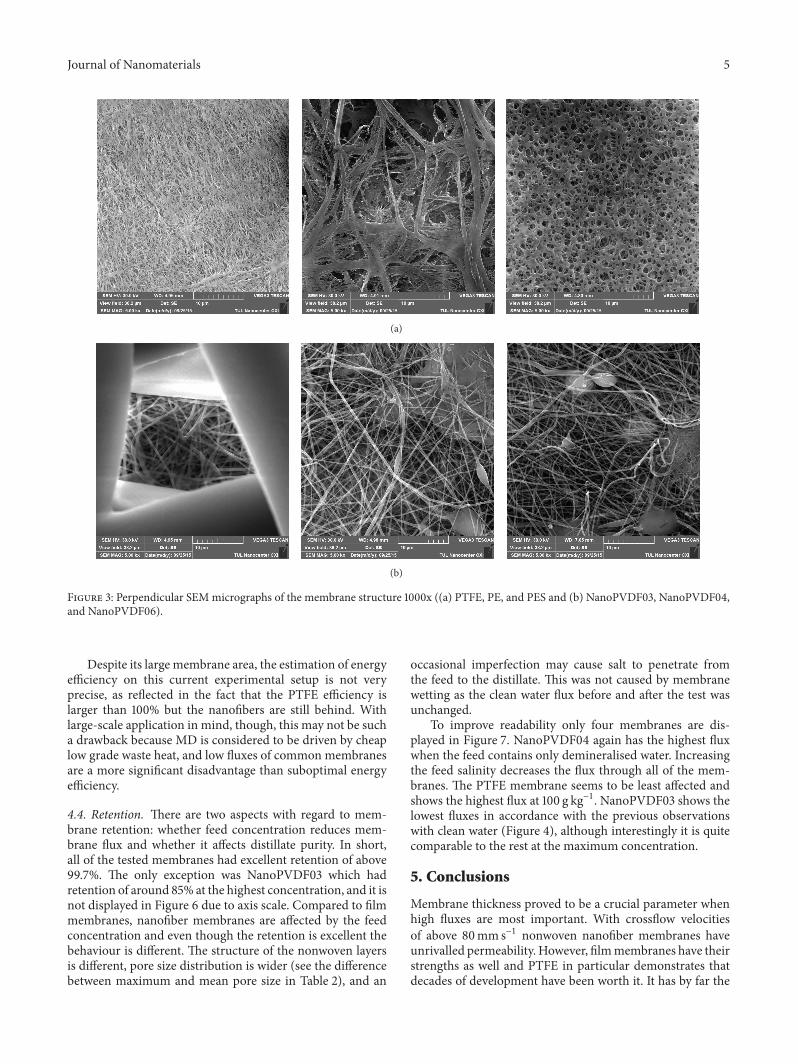
The film membranes have different structures from eachother (Figure 3). PTFE has the finest structure, PE has ratherlarge shapes, and PES has small circular pores.The nanofibershave a similar look, and in all cases the PVDF fiber diameterwas around 200 nm. The structure is not uniform, withoccasional polymer drops or fusing caused by nonevaporatedsolvent.
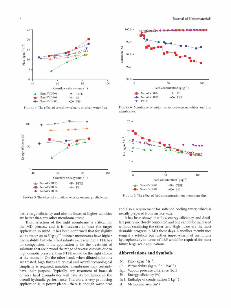
4.2. Flux. Figure 4 shows the effect of crossflow velocityon demineralised water flux. All of the nanofiber mem-branes respond better to an increase in crossflow velocity.NanoPVDF04 with one-side lamination shows the highestfluxes thanks to its small thickness, even though thinner
membranes should suffer more from temperature polariza-tion. Larger pores do not contribute to flux increase, as poresize beyond 0.3 𝜇m should not have a significant effect [15].
Two-side lamination spoils the membrane performance.NanoPVDF03 has the same thickness as NanoPVDF04 butthe fluxes are significantly smaller at all crossflow velocities.The effect of crossflow velocity is smaller on the film mem-branes, and at smaller flowrates their fluxes are comparableto the better nanofiber membranes.
4.3. Energy Efficiency. Energy efficiency should increase withhigher crossflow velocities (Figure 5), as the effective heat ofcondensation increases with flux, whereas the lossy heat ofconduction remains about the same.This is stated because thedriving force was set according to LMTD, which accounts forall four inlet and outlet temperatures and not only for the feedand distillateΔ𝑇.There is a clear difference between the thickfilm and thin nonwoven membranes, the latter having muchworse energy efficiency. The thermal conductivity of PTFE isabout the same as PVDF but thanks to the PTFE thicknessand superb hydrophobicity, it is assumed that only vapour ispresent in the membrane pores and heat losses are negligible.
Journal of Nanomaterials 5
(a)
(b)
Figure 3: Perpendicular SEMmicrographs of the membrane structure 1000x ((a) PTFE, PE, and PES and (b) NanoPVDF03, NanoPVDF04,and NanoPVDF06).
Despite its large membrane area, the estimation of energyefficiency on this current experimental setup is not veryprecise, as reflected in the fact that the PTFE efficiency islarger than 100% but the nanofibers are still behind. Withlarge-scale application in mind, though, this may not be sucha drawback because MD is considered to be driven by cheaplow grade waste heat, and low fluxes of common membranesare a more significant disadvantage than suboptimal energyefficiency.
4.4. Retention. There are two aspects with regard to mem-brane retention: whether feed concentration reduces mem-brane flux and whether it affects distillate purity. In short,all of the tested membranes had excellent retention of above99.7%. The only exception was NanoPVDF03 which hadretention of around 85% at the highest concentration, and it isnot displayed in Figure 6 due to axis scale. Compared to filmmembranes, nanofiber membranes are affected by the feedconcentration and even though the retention is excellent thebehaviour is different. The structure of the nonwoven layersis different, pore size distribution is wider (see the differencebetween maximum and mean pore size in Table 2), and an
occasional imperfection may cause salt to penetrate fromthe feed to the distillate. This was not caused by membranewetting as the clean water flux before and after the test wasunchanged.
To improve readability only four membranes are dis-played in Figure 7. NanoPVDF04 again has the highest fluxwhen the feed contains only demineralised water. Increasingthe feed salinity decreases the flux through all of the mem-branes. The PTFE membrane seems to be least affected andshows the highest flux at 100 g kg−1. NanoPVDF03 shows thelowest fluxes in accordance with the previous observationswith clean water (Figure 4), although interestingly it is quitecomparable to the rest at the maximum concentration.
5. Conclusions
Membrane thickness proved to be a crucial parameter whenhigh fluxes are most important. With crossflow velocitiesof above 80mm s−1 nonwoven nanofiber membranes haveunrivalled permeability. However, filmmembranes have theirstrengths as well and PTFE in particular demonstrates thatdecades of development have been worth it. It has by far the
6 Journal of Nanomaterials
PEPES
NanoPVDF03NanoPVDF04NanoPVDF06
PTFE
60 80 10040Crossflow velocity (mm s−1)
0
5
10
15
20
25
Flux
(kg m
−2
h−1)
Figure 4: The effect of crossflow velocity on clean water flux.
0
50
100
Ener
gy effi
cien
cy (%
)
60 80 10040
PENanoPVDF03NanoPVDF04NanoPVDF06
PTFE
Crossflow velocity (mm s−1)
Figure 5: The effect of crossflow velocity on energy efficiency.
best energy efficiency and also its fluxes at higher salinitiesare better than any other membrane tested.
Thus, selection of the right membrane is critical forthe MD process, and it is necessary to bear the targetapplication in mind. It has been confirmed that for slightlysaline water up to 50 g kg−1 thinner membranes have higherpermeability, but when feed salinity increases then PTFE hasno competition. If the application is for the treatment ofsolutions that are beyond the range of reverse osmosis due tohigh osmotic pressure, then PTFE would be the right choiceat the moment. On the other hand, when diluted solutionsare treated, high fluxes are crucial and overall technologicalsimplicity is required; nanofiber membranes may certainlyhave their purpose. Typically, any treatment of brackishor very hard groundwater will have its bottleneck in theoverall hydraulic performance. Therefore, a very promisingapplication is in power plants—there is enough waste heat
Feed concentration (g kg−1)
PESPENanoPVDF04
NanoPVDF06PTFE
50 100099.6
99.7
99.8
99.9
100.0
Rete
ntio
n (%
)
Figure 6: Membrane retention varies between nanofiber and filmmembranes.
PESNanoPVDF03NanoPVDF04
PTFE
0
5
10
15
20
25Fl
ux (k
g m−2
h−1)
50 1000Feed concentration (g kg−1)
Figure 7: The effect of feed concentration on membrane flux.
and also a requirement for softened cooling water, which isusually prepared from surface water.
It has been shown that flux, energy efficiency, and distil-late purity are closely connected and one cannot be increasedwithout sacrificing the other two. High fluxes are the mostdesirable progress in MD these days. Nanofiber membranessuggest a solution but further improvement of membranehydrophobicity in terms of LEP would be required for mostfuture large-scale applications.
Abbreviations and Symbols
𝑁: Flux (kgm−2 h−1)𝐶: Permeability (kgm−2 h−1 bar−1)Δ𝑝: Vapour pressure difference (bar)𝐸: Energy efficiency (%)Δ𝐻: Enthalpy of condensation (J kg−1)𝐴: Membrane area (m2)

Journal of Nanomaterials 7
𝑚: Mass flowrate (kg s−1)𝐶𝑝: Heat capacity at constant pressure
(J kg−1 K−1)Δ𝑇: Temperature difference (∘C)LMTD: Logarithmic mean temperature difference
(∘C)𝑎𝑤: Activity of water (1)𝑅: Retention (%)𝐶𝑓: Feed concentration (g kg−1)𝐶𝑑: Distillate concentration (g kg−1)
LEP: Liquid entry pressure (bar)DCMD: Direct contact membrane distillationMD: Membrane distillationPTFE: PolytetrafluoroethylenePE: PolyethylenePES: PolyethersulfonePP: PolypropylenePVDF: Polyvinylidene fluoride.
Competing Interests
The authors declare that there is no conflict of interestsregarding the publication of this paper.
Acknowledgments
The presented results were achieved in the framework ofthe project LO1418 “Progressive Development of MembraneInnovation Centre,” supported by the program NPU I Min-istry of Education, Youth and Sports of the Czech Republic,using the infrastructure of theMembrane Innovation Centre.The research was also supported by the Ministry of Edu-cation, Youth and Sports in the framework of the targetedsupport of the “National Programme for Sustainability I”LO 1201 and the OPR&DI project “Centre for Nanomateri-als, Advanced Technologies and Innovation,” CZ.1.05/2.1.00/01.0005. The authors would also like to thank Bart Nelemansof Aquastill for providing the film PTFE, PES, and PEmembranes.
References
[1] E. Drioli, A. Ali, and F. Macedonio, “Membrane distillation:recent developments and perspectives,” Desalination, vol. 356,pp. 56–84, 2015.
[2] F. Lagana, G. Barbieri, and E. Drioli, “Direct contact membranedistillation: modelling and concentration experiments,” Journalof Membrane Science, vol. 166, no. 1, pp. 1–11, 2000.
[3] S. Al-Obaidani, E. Curcio, F. Macedonio, G. Di Profio, H. Al-Hinai, and E. Drioli, “Potential of membrane distillation inseawater desalination: thermal efficiency, sensitivity study andcost estimation,” Journal ofMembrane Science, vol. 323, no. 1, pp.85–98, 2008.
[4] A. Alkhudhiri, N. Darwish, and N. Hilal, “Membrane distilla-tion: a comprehensive review,” Desalination, vol. 287, pp. 2–18,2012.
[5] D. Lukas, A. Sarkar, L. Martinova et al., “Physical principles ofelectrospinning (electrospinning as a nano-scale technology ofthe twenty-first century),” Textile Progress, vol. 41, no. 2, pp. 59–140, 2009.
[6] F. Yener and O. Jirsak, “Comparison between the needle androller electrospinning of polyvinylbutyral,” Journal of Nanoma-terials, vol. 2012, Article ID 839317, 6 pages, 2012.
[7] C. Basheer, “Nanofiber-membrane-supported TiO2as a catalyst
for oxidation of benzene to phenol,” Journal of Chemistry, vol.2013, Article ID 562305, 7 pages, 2013.
[8] A. Haider, S. Kwak, K. C. Gupta, and I.-K. Kang, “Antibacterialactivity and cytocompatibility of PLGA/CuO hybrid nanofiberscaffolds prepared by electrospinning,” Journal of Nanomateri-als, vol. 2015, Article ID 832762, 10 pages, 2015.
[9] F. Yalcinkaya, M. Komarek, D. Lubasova, F. Sanetrnik, and J.Maryska, “Preparation of antibacterial nanofibre/nanoparticlecovered composite yarns,” Journal of Nanomaterials, vol. 2016,Article ID 7565972, 7 pages, 2016.
[10] N. Nuraje, W. S. Khan, Y. Lei, M. Ceylan, and R. Asmatulu,“Superhydrophobic electrospun nanofibers,” Journal of Materi-als Chemistry A, vol. 1, no. 6, pp. 1929–1946, 2013.
[11] A. Razmjou, E. Arifin, G. Dong, J. Mansouri, and V.Chen, “Superhydrophobicmodification of TiO
2nanocomposite
PVDF membranes for applications in membrane distillation,”Journal of Membrane Science, vol. 415-416, pp. 850–863, 2012.
[12] C. Yang, X.-M. Li, J. Gilron et al., “CF4 plasma-modified super-hydrophobic PVDF membranes for direct contact membranedistillation,” Journal of Membrane Science, vol. 456, pp. 155–161,2014.
[13] L. Eykens, I. Hitsov, K. De Sitter et al., “Influence of membranethickness and process conditions on direct contact membranedistillation at different salinities,” Journal of Membrane Science,vol. 498, pp. 353–364, 2016.
[14] B. L. Pangarkar, M. G. Sane, and M. Guddad, “Reverse osmosisand membrane distillation for desalination of groundwater: areview,” ISRN Materials Science, vol. 2011, Article ID 523124, 9pages, 2011.
[15] M. I. Ali, E. K. Summers, H. A. Arafat, and J. H. Lienhard V,“Effects of membrane properties on water production cost insmall scale membrane distillation systems,” Desalination, vol.306, pp. 60–71, 2012.

Submit your manuscripts athttp://www.hindawi.com
ScientificaHindawi Publishing Corporationhttp://www.hindawi.com Volume 2014
CorrosionInternational Journal of
Hindawi Publishing Corporationhttp://www.hindawi.com Volume 2014
Polymer ScienceInternational Journal of
Hindawi Publishing Corporationhttp://www.hindawi.com Volume 2014
Hindawi Publishing Corporationhttp://www.hindawi.com Volume 2014
CeramicsJournal of
Hindawi Publishing Corporationhttp://www.hindawi.com Volume 2014
CompositesJournal of
NanoparticlesJournal of
Hindawi Publishing Corporationhttp://www.hindawi.com Volume 2014
Hindawi Publishing Corporationhttp://www.hindawi.com Volume 2014
International Journal of
Biomaterials
Hindawi Publishing Corporationhttp://www.hindawi.com Volume 2014
NanoscienceJournal of
TextilesHindawi Publishing Corporation http://www.hindawi.com Volume 2014
Journal of
NanotechnologyHindawi Publishing Corporationhttp://www.hindawi.com Volume 2014
Journal of
CrystallographyJournal of
Hindawi Publishing Corporationhttp://www.hindawi.com Volume 2014
The Scientific World JournalHindawi Publishing Corporation http://www.hindawi.com Volume 2014
Hindawi Publishing Corporationhttp://www.hindawi.com Volume 2014
CoatingsJournal of
Advances in
Materials Science and EngineeringHindawi Publishing Corporationhttp://www.hindawi.com Volume 2014
Smart Materials Research
Hindawi Publishing Corporationhttp://www.hindawi.com Volume 2014
Hindawi Publishing Corporationhttp://www.hindawi.com Volume 2014
MetallurgyJournal of
Hindawi Publishing Corporationhttp://www.hindawi.com Volume 2014
BioMed Research International
MaterialsJournal of
Hindawi Publishing Corporationhttp://www.hindawi.com Volume 2014
Nano
materials
Hindawi Publishing Corporationhttp://www.hindawi.com Volume 2014
Journal ofNanomaterials