member of the ams group
TRANSCRIPT

CMOSIS / AWAIBA
is now
Member of the
ams Group
The technical content of this CMOSIS / AWAIBA document is still valid.
Contact information:
Headquarters:
ams AG
Tobelbaderstrasse 30
8141 Premstaetten, Austria
Tel: +43 (0) 3136 500 0
e-Mail: [email protected]
Please visit our website at www.ams.com

MityCAM-C8000 – MityViewer Quick Start Guide
1 Critical Link, LLC PHONE 315.425.4045 6712 Brooklawn Pkwy FAX 315.425.4048
Syracuse, NY 13211 www.CriticalLink.com
The MityCAM-C8000 MityViewer Quick Start Guide will guide you through the software installation process
and the steps to acquire your first image with the MityViewer application.
Contents 1 Revision History ....................................................................................................................................................... 2
2 Interface Options ..................................................................................................................................................... 2
2.1 Setup USB/RNDIS PC Adapter ........................................................................................................................... 2
2.2 Gigabit Ethernet Enabled MityCAM Setup ......................................................................................................... 3
3 Install MityViewer Software ..................................................................................................................................... 4
4 Acquire First Image .................................................................................................................................................. 8
4.1 Launch MityViewer ........................................................................................................................................... 8
4.2 MityViewer ....................................................................................................................................................... 9
4.3 Launch Log Viewer ............................................................................................................................................ 9
4.4 Connecting to Camera .....................................................................................................................................10
4.5 Sensor Configuration and Calibration ...............................................................................................................13
4.5.1 Mirroring .................................................................................................................................... 13
4.5.2 Gain/Offset ................................................................................................................................. 13
4.5.3 Registers..................................................................................................................................... 13
4.5.4 GPIO .......................................................................................................................................... 13
4.6 CMV Snapshot Control .....................................................................................................................................15
4.6.1 Background Subtraction ............................................................................................................. 15
4.6.2 Test Pattern ................................................................................................................................ 15
4.6.3 Number of Frames ...................................................................................................................... 15
4.6.4 Timing........................................................................................................................................ 15
4.6.5 ROI ............................................................................................................................................ 15
4.6.6 Stop Capture, Image Info and Start Capture ................................................................................ 15
4.7 Acquire Image .................................................................................................................................................17
4.8 Display Image ..................................................................................................................................................18
5 Saving Image Data to File ........................................................................................................................................19
6 Select / Change ROI ................................................................................................................................................20
7 Stream Image Data to PC / Laptop ..........................................................................................................................21
8 Stream Image Data to Internal Memory ..................................................................................................................22

MityCAM-C8000 – MityViewer Quick Start Guide
2 Critical Link, LLC PHONE 315.425.4045 6712 Brooklawn Pkwy FAX 315.425.4048
Syracuse, NY 13211 www.CriticalLink.com
9 Record / Playback Images to / from disk .................................................................................................................23
10 Image Statistics.......................................................................................................................................................24
10.1 Image Statistics Dialog .....................................................................................................................................24
10.2 Plot Statistics ...................................................................................................................................................24
10.3 Important notes related to the Noise Statistic Plug-in ......................................................................................26
Mean by Rows ......................................................................................................................................... 26
Mean by Cols ........................................................................................................................................... 26
Standard Deviation by Column ................................................................................................................ 26
Standard Deviation by Row ..................................................................................................................... 26
FFT .......................................................................................................................................................... 27
Comments ................................................................................................................................................ 27
10.4 Peak Finder Dialog ...........................................................................................................................................28
1 Revision History
Revision Date Notes
Draft 8/14/2014 Draft Release
1.0 8/22/2014 Initial 1.0 Release
1.1 2/10/2015 Added additional feature descriptions
1.2 3/12/2015 Added section on noise statistics and peak detect
1.3 4/06/2015 Added section on Playback/Record
2 Interface Options
2.1 Setup USB/RNDIS PC Adapter
All MityCAM-C8000 models feature the option to send image data over the USB 2.0 interface of the camera.
This communication occurs over a USB 2.0 Remote Network Driver Interface Specification (RNDIS) to a PC.
The camera is already configured to have an IP address of 10.1.47.2 for this interface and the PC should
configure its corresponding RNDIS USB Gadget address to be 10.1.47.1.
This device should have been configured using the Hardware Setup Guide that was included with the
MityCAM. If this has not been performed yet, then please follow the steps outlined in that guide.
In addition to image capture with the MityViewer application the USB interface allows SSH access to the
camera for configuration and debug activities.

MityCAM-C8000 – MityViewer Quick Start Guide
3 Critical Link, LLC PHONE 315.425.4045 6712 Brooklawn Pkwy FAX 315.425.4048
Syracuse, NY 13211 www.CriticalLink.com
2.2 Gigabit Ethernet Enabled MityCAM Setup
For MityCAM-C8000 cameras that feature the Gigabit Ethernet interface type configuration of the USB/RNDIS
interface is not recommended for image capture as the Ethernet interface offers superior frame rate capabilities.
Each MityCAM is pre-configured to obtain an IP address from a DHCP server running on a network. If directly
connecting to a PC a DHCP server would need to be run on the PC or the camera must be configured to use a
static IP address instead. Please contact your Critical Link account representative for further details about how
to make such modifications.
Once the camera and the PC are connected to the same DHCP enabled network no other configuration is
necessary to communicate using the MityViewer application, once installed on the PC, Section 3.

MityCAM-C8000 – MityViewer Quick Start Guide
4 Critical Link, LLC PHONE 315.425.4045 6712 Brooklawn Pkwy FAX 315.425.4048
Syracuse, NY 13211 www.CriticalLink.com
3 Install MityViewer Software The MityViewer is a Windows PC application which lets you setup and configure the CMV8000 sensor/camera
as well as acquire and display image data. Follow the steps below to install the MityViewer application on your
PC.
Installing the application on your computer will create shortcuts to start it under the standard menus
(StartProgramsCritical LinkMityCCD on a Windows based computer). During the installation, you will
be able to select which plugin elements you wish to install. Some of the plugins are designed for factory and/or
development use and will require keys to install. The default set should be adequate for the majority of users.
1. Select the application (MityViewer_setup_2_X_X.exe) from the CD / DVD and then follow the prompts

MityCAM-C8000 – MityViewer Quick Start Guide
5 Critical Link, LLC PHONE 315.425.4045 6712 Brooklawn Pkwy FAX 315.425.4048
Syracuse, NY 13211 www.CriticalLink.com
Figure 1: Software License Information
Figure 2: All components are selected by default
MityCAM-C8000 – MityViewer Quick Start Guide
6 Critical Link, LLC PHONE 315.425.4045 6712 Brooklawn Pkwy FAX 315.425.4048
Syracuse, NY 13211 www.CriticalLink.com
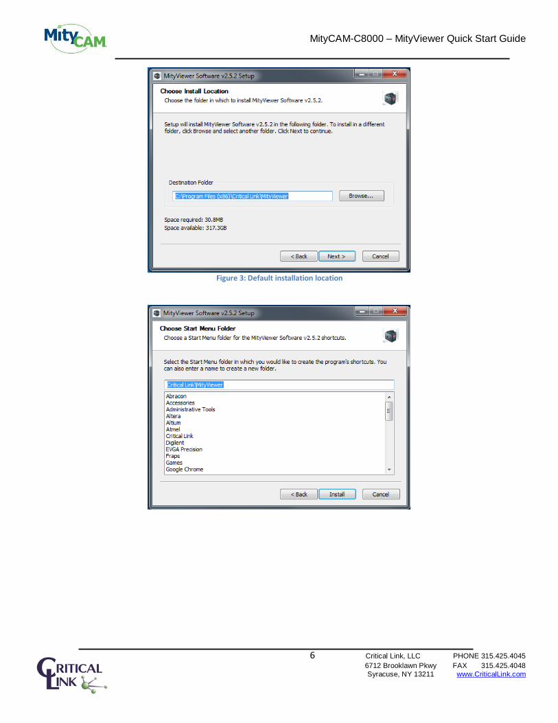
Figure 3: Default installation location

MityCAM-C8000 – MityViewer Quick Start Guide
7 Critical Link, LLC PHONE 315.425.4045 6712 Brooklawn Pkwy FAX 315.425.4048
Syracuse, NY 13211 www.CriticalLink.com

MityCAM-C8000 – MityViewer Quick Start Guide
8 Critical Link, LLC PHONE 315.425.4045 6712 Brooklawn Pkwy FAX 315.425.4048
Syracuse, NY 13211 www.CriticalLink.com
4 Acquire First Image This section discusses the steps needed to connect to the camera, launch the MityViewer software and acquire
the first image.
4.1 Launch MityViewer Launch the MityViewer software by going to the Windows Start menu and typing MityViewer. The program
will start and the desktop will appear (Windows 7). Alternatively you can also find the application in your start
menu under StartProgramsCritical LinkMityViewer.
MityCAM-C8000 – MityViewer Quick Start Guide
9 Critical Link, LLC PHONE 315.425.4045 6712 Brooklawn Pkwy FAX 315.425.4048
Syracuse, NY 13211 www.CriticalLink.com
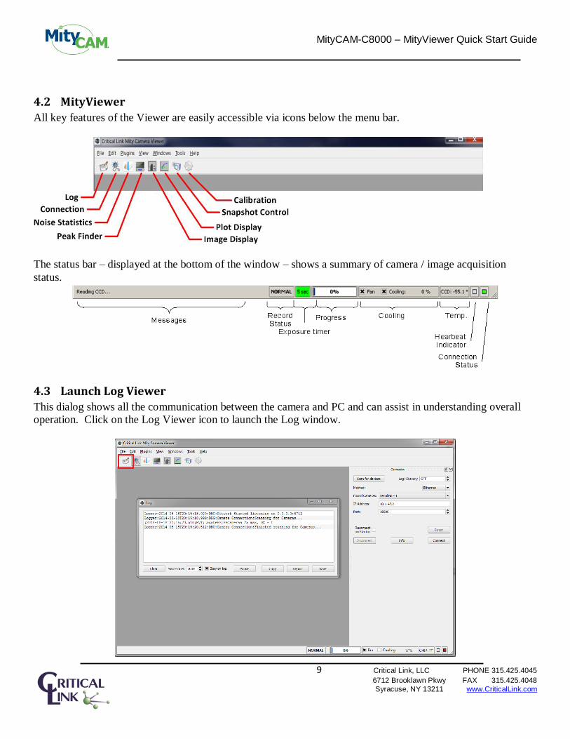
4.2 MityViewer
All key features of the Viewer are easily accessible via icons below the menu bar.
The status bar – displayed at the bottom of the window – shows a summary of camera / image acquisition
status.
4.3 Launch Log Viewer
This dialog shows all the communication between the camera and PC and can assist in understanding overall
operation. Click on the Log Viewer icon to launch the Log window.

MityCAM-C8000 – MityViewer Quick Start Guide
10 Critical Link, LLC PHONE 315.425.4045 6712 Brooklawn Pkwy FAX 315.425.4048
Syracuse, NY 13211 www.CriticalLink.com
4.4 Connecting to Camera
1. Attach USB Cable (for RNDIS USB Gadget) from the PC to the camera if not already done
2. Turn power on to the camera and you should immediately hear the fan turn on. Note, it takes the camera
approximately 20 seconds to boot-up from a power-on cycle so you may need to wait 20 ~ 45 seconds to
connect successfully. You should see a green status LED through the fan grill on the rear of the camera
if it is running and “ready”.
3. If the connection dialog is not open, then select the connection icon form menu bar
4. Select Ethernet as the communication method
5. Select Scan for devices button
6. Wait for a few seconds and the camera S/N should appear on the Found Cameras drop down list. If the
Found Cameras drop down list is empty, then select Scan for devices again. If you have multiple
cameras on your network, then all Found Cameras should appear in this drop down list.
7. Select the camera based on S/N. A printed label with S/N may be found on the back of the camera.

MityCAM-C8000 – MityViewer Quick Start Guide
11 Critical Link, LLC PHONE 315.425.4045 6712 Brooklawn Pkwy FAX 315.425.4048
Syracuse, NY 13211 www.CriticalLink.com
8. Select Connect button and observe display on Log Viewer. If the connect fails initially, then select the
Connect button a second time.
9. Once the camera has successfully connected, then two green indicators will appear on the bottom right
of the status bar. The right-most green indicator indicates connection to the camera. The indicator next
to the left most indicator flashes green and indicates receipt of a periodic heartbeat message from the
camera. A message indicating that the Camera Connection Established also appears on the bottom
left.
MityCAM-C8000 – MityViewer Quick Start Guide
12 Critical Link, LLC PHONE 315.425.4045 6712 Brooklawn Pkwy FAX 315.425.4048
Syracuse, NY 13211 www.CriticalLink.com
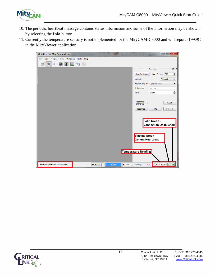
10. The periodic heartbeat message contains status information and some of the information may be shown
by selecting the Info button.
11. Currently the temperature sensory is not implemented for the MityCAM-C8000 and will report -199.9C
in the MityViewer application.

MityCAM-C8000 – MityViewer Quick Start Guide
13 Critical Link, LLC PHONE 315.425.4045 6712 Brooklawn Pkwy FAX 315.425.4048
Syracuse, NY 13211 www.CriticalLink.com
4.5 Sensor Configuration and Calibration
1. Select the CMV Calibration icon to display the Calibration Control Panel.
4.5.1 Mirroring 1. If desired you can mirror the image over both the horizontal and vertical axes.
4.5.2 Gain/Offset
All settings in the Gain/Offset section directly manipulate the sensors registers.
1. The programmable gain amplifier, PGA, can be set to one of 5 values; 1.0, 1.33 (default), 2, 3 and 4.
2. ADC Gain can be set to a value between 0 and 64 with 32 being the default.
3. Offset is a digital bias on the data and can be set to a value between 0 and 2047 with 444 being the
default.
4.5.3 Registers 1. If necessary it is possible to read and write registers within the MityCAM-C8000 camera itself through
the Peek and Poke buttons. Note that it is possible to damage or cause the MityCAM-C8000 to become
inoperable using this feature. An address or data must be provided in hex format.
4.5.4 GPIO 1. The GPIO section of the CMV calibration tool allows the configuration of the 4 GPIOs accessible on the
rear side of the camera. Please contact your Critical Link representative if a GPIO interface cable is
needed as one is not included.

MityCAM-C8000 – MityViewer Quick Start Guide
14 Critical Link, LLC PHONE 315.425.4045 6712 Brooklawn Pkwy FAX 315.425.4048
Syracuse, NY 13211 www.CriticalLink.com
Figure 4: CMV Calibration

MityCAM-C8000 – MityViewer Quick Start Guide
15 Critical Link, LLC PHONE 315.425.4045 6712 Brooklawn Pkwy FAX 315.425.4048
Syracuse, NY 13211 www.CriticalLink.com
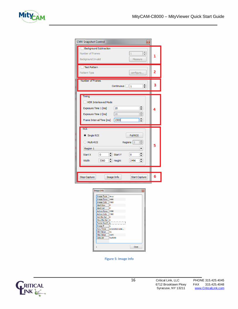
4.6 CMV Snapshot Control Select the CMV Snapshot Control icon to display the Snapshot Control Panel.
4.6.1 Background Subtraction 1. Number of Frames sets the number of frames that will be averaged together
2. Measure captures the specified number of background frames
To view the corrected image using the background subtraction select the Source -> Corrected Area option in the
Snapshot Display.
4.6.2 Test Pattern 1. The Test Pattern feature is not yet implemented for the MityCAM-C8000 camera.
4.6.3 Number of Frames 1. The Number of Frames option sets either the total number of frames captured upon press of the Start
Capture button if the Continuous check box is unchecked.
2. If the Continuous check box is selected then the number of frames cannot be set as the camera will
capture frames and transmit them to MityViewer as quickly as possible.
4.6.4 Timing 1. When HDR Interleaved Mode each row of camera data will be captured at alternating exposure times
based on Exposure Time 1 and Exposure Time 2.
2. Exposure Time 1 is used for all rows of data when HDR Interleaved Mode is not enabled.
3. Exposure Time 2 is only available in HDR interleaved mode.
4. The Frame Interval Time [ms] is the amount of time between two subsequent frame captures.
4.6.5 ROI 1. Please reference Section 0 for details about using the ROI options.
4.6.6 Stop Capture, Image Info and Start Capture 1. Stop Capture causes the camera to stop sending image data to MityViewer. This should be used prior to
changing any settings in the Snapshot Control panel.
2. Start Capture causes the camera to begin sending camera data using the settings specified in the
Snapshot Control panel.
3. Image Info displays the settings used for the last image captured.
MityCAM-C8000 – MityViewer Quick Start Guide
16 Critical Link, LLC PHONE 315.425.4045 6712 Brooklawn Pkwy FAX 315.425.4048
Syracuse, NY 13211 www.CriticalLink.com
Figure 5: Image Info

MityCAM-C8000 – MityViewer Quick Start Guide
17 Critical Link, LLC PHONE 315.425.4045 6712 Brooklawn Pkwy FAX 315.425.4048
Syracuse, NY 13211 www.CriticalLink.com
4.7 Acquire Image 1. Select the snapshot icon to display the Snapshot Control Panel.
2. Set Number of Frames to 1 and keep the Continuous check box unchecked.
3. Set Exposure Time to 20 ms.
4. Set Frame Interval Time to 1500 ms.
5. Set Single ROI. The width should be 3360 and the height should be 2496.
6. Select Start Capture.

MityCAM-C8000 – MityViewer Quick Start Guide
18 Critical Link, LLC PHONE 315.425.4045 6712 Brooklawn Pkwy FAX 315.425.4048
Syracuse, NY 13211 www.CriticalLink.com
4.8 Display Image 1. To view the Image Data, load a Snapshot Display. Click on the FileNewSnapshot Display menu.
2. Select the Raw Image as the Source Snapshot Display.
3. Select Scale Color to Data checkbox.
4. An image should appear on the Snapshot Display control panel.
5. Adjust the lens iris and focus and select Start Capture on the Snapshot Control panel.
6. You may also select Continuous on the Snapshot Control panel followed by Start Capture to
continuously acquire images. Select Stop Capture to stop acquisition. Note, don’t make any changes to
the Exposure Time or Frame Interval Time during continuous acquisition.

MityCAM-C8000 – MityViewer Quick Start Guide
19 Critical Link, LLC PHONE 315.425.4045 6712 Brooklawn Pkwy FAX 315.425.4048
Syracuse, NY 13211 www.CriticalLink.com
5 Saving Image Data to File 1. You may save an image data as a CSV, TIFF or binary CDI format.
2. Select File Save and a dialog will prompt you for the file type.
3. The file may be analyzed at a later time using MS Excel or another application.

MityCAM-C8000 – MityViewer Quick Start Guide
20 Critical Link, LLC PHONE 315.425.4045 6712 Brooklawn Pkwy FAX 315.425.4048
Syracuse, NY 13211 www.CriticalLink.com
6 Select / Change ROI The ability to set the ROI for the MityCAM-C8000 can be found in the Snapshot Control settings dialog,
Section 4.6.
By default, the Region of Interest (ROI) is set to the maximum size of the sensor and only a single region.
CMV8000: 0,0 – 2496, 3360
You may also select multiple Regions of Interest. Up to a total of 8 different ROI regions may be set in the
MityViewer application. Each region has a specified Start X, Start Y, Width and Height.
1. Use the Regions box to set the number of regions from 2 to 8
2. For each Region that is enabled a set of settings will be available which can be set by changing the
Region N drop down menu.
3. For each Region a Start X, Start Y, Width and Height may be specified.
You may change the ROI by modifying the Start Row / Column and End Row / Column in the CIS Snapshot
Control dialog. Note the following rules for changing the ROI:
Total Bytes = Width x Height x 2
Total Bytes = N x BL
N must be an integer number
BL must be evenly divisible by 8
32K <= BL < 64K
The simplest way is to use regions that are multiples of 16K pixels (e.g. 16x1024) or are less than 32K
pixels in size
MityCAM-C8000 – MityViewer Quick Start Guide
21 Critical Link, LLC PHONE 315.425.4045 6712 Brooklawn Pkwy FAX 315.425.4048
Syracuse, NY 13211 www.CriticalLink.com
7 Stream Image Data to PC / Laptop 1. To view the Image Data, load a Snapshot Display. Click on the FileNewSnapshot Display menu.
2. Select the Raw Image as the Source Snapshot Display.
3. Select Scale Color to Data checkbox
4. Setup Exposure Time in the Snapshot Control panel
5. Setup Frame Interval Time in the Snapshot Control panel. Ensure that the Frame Interval Time is at
least 1500 ms for CMV8000 sensor (full ROI)
6. Select Continuous on the Snapshot Control panel
7. Select Start Capture to continuously acquire images.
8. Select Stop Capture to stop acquisition. Note, don’t make any changes to the Exposure Time or
Frame Interval Time during acquisition

MityCAM-C8000 – MityViewer Quick Start Guide
22 Critical Link, LLC PHONE 315.425.4045 6712 Brooklawn Pkwy FAX 315.425.4048
Syracuse, NY 13211 www.CriticalLink.com
8 Stream Image Data to Internal Memory 1. To view the Image Data, load a Snapshot Display. Click on the FileNewSnapshot Display menu.
2. Select the Raw Image as the Source Snapshot Display.
3. Select Scale Color to Data checkbox
4. Setup Exposure Time in the Snapshot Control panel
5. Setup Frame Interval Time in the Snapshot Control panel. The Frame Interval Time can be set to
any value greater than 1000 ms for CMV8000 sensor (full ROI)
6. Unselect Continuous on the Snapshot Control panel
7. Select Number of Frames to be greater than 1 (maximum is 20)
8. Select Start Capture to continuously acquire images.
9. Acquisition will stop after the number of frames has been acquired. The image data is captured at 20
frames/sec rate (Frame Interval = 1000 ms) and sent to the PC at a slower rate

MityCAM-C8000 – MityViewer Quick Start Guide
23 Critical Link, LLC PHONE 315.425.4045 6712 Brooklawn Pkwy FAX 315.425.4048
Syracuse, NY 13211 www.CriticalLink.com
9 Record / Playback Images to / from disk 1. The MityViewer can be configured to stream received images to disk by using the Playback / Record
dialog accessible via the main window View menu.
2. The Playback / Record dialog supports recording TIFF files as well as a custom format named CDI
(continuous data inject). Select the desired format using the menu option next to the file select button,
.
3. Select the file select button to choose a record file name that will contain meta-data information needed
for playback. The location of this file also will include the image files stored to disk during a record
session. If an existing recording is selected (for playback, or to overwrite), the number of images in the
record session will be shown.
4. To start recording, press the record button, . The dialog will prompt you if you will be
overwriting an existing record set. Each image acquired is saved to disk before being passed to the rest
of the application for processing.
5. To stop recording, press the stop button, .
6. To playback a record set, press the play button, . Images played back are injected as if they came
from the camera DLL (before any application processing). During playback, the play button will
change to a pause button, .
7. To stop playback, click the stop button.

MityCAM-C8000 – MityViewer Quick Start Guide
24 Critical Link, LLC PHONE 315.425.4045 6712 Brooklawn Pkwy FAX 315.425.4048
Syracuse, NY 13211 www.CriticalLink.com
10 Image Statistics
10.1 Image Statistics Dialog
The Image Noise Statistics dialog is shown using its icon on the toolbar. When the Enable box is checked,
this dialog will compute image statistics on every acquired image. When acquiring images at high frame rates,
you may need to disable this dialog to achieve the desired throughput (depending on your PC’s CPU). The
dialog computes the image mean pixel value, the noise (std deviation) value, and shows how many pixels fall
outside of 1,2,3, and 4 sigma from the noise value as a percentage. The nominal values for these percentages
(based on a Gaussian distribution) are shown to the right of the values). You can reduce the size of the
considered area by adjusting the X Margin and Y Margin controls. These values are applied to both edges of
the X or Y limits. The noise computation is a multi-pass operation. First it does a sliding window average (using
the Window setting for the size of the window) across a row. Any pixel who’s value is more than Peak Cutoff
counts above the average is discarded for the computation and the average of its one-away neighbors is used for
the computation (the actual pixel data is untouched). Once this peak shearing operation is done, the line mean is
computed and used to derive the noise figure. The running average noise and mean values are displayed next to
the image mean and noise fields. Pressing the Reset Averages button clears the running average.
10.2 Plot Statistics The Image Noise Statistics dialog can compute image statistics suitable for plotting using the plot display
window. Clicking the Generate button will compute the following data sets:

MityCAM-C8000 – MityViewer Quick Start Guide
25 Critical Link, LLC PHONE 315.425.4045 6712 Brooklawn Pkwy FAX 315.425.4048
Syracuse, NY 13211 www.CriticalLink.com
StdDev by Row StdDev for each pixel in a row
StdDev by Column StdDev for each pixel in a column
Mean by Row Mean value across a row
Mean by Column Mean value along a column
Data by Row Image data in a given row
Data by Column Image data in a given column
FFT by Row FFT [1024 bin] of the data in a row
Histogram Image histogram.
Checking the Auto box will cause the dialog to compute image plot statistics for every image acquired. You
may find this is too much for your CPU to handle.

MityCAM-C8000 – MityViewer Quick Start Guide
26 Critical Link, LLC PHONE 315.425.4045 6712 Brooklawn Pkwy FAX 315.425.4048
Syracuse, NY 13211 www.CriticalLink.com
10.3 Important notes related to the Noise Statistic Plug-in
This plug-in was primarily developed to support internal testing of a number CCDs and CMOS arrays. The
plug-n is available for customer use, but please note the following limitations, caveats, and definitions.
All of the statistics a developed using a local Area Mean matrix developed from the input image, X, and the
specified kernel size of the noise statistics dialog. The equation for the Area Mean matrix is given by:
𝐴𝑟𝑒𝑎𝑀𝑒𝑎𝑛𝑟𝑜𝑤,𝑐𝑜𝑙 =∑ ∑ 𝑋𝑖,𝑗
𝑐𝑜𝑙+𝑘𝑒𝑟𝑛𝑒𝑙𝑠𝑖𝑧𝑒𝑗=𝑐𝑜𝑙−𝑘𝑒𝑟𝑛𝑒𝑙𝑠𝑖𝑧𝑒
𝑟𝑜𝑤+𝑘𝑒𝑟𝑛𝑒𝑙𝑠𝑖𝑧𝑒𝑖=𝑟𝑜𝑤−𝑘𝑒𝑟𝑛𝑒𝑙𝑠𝑖𝑧𝑒
(2𝑥𝑘𝑒𝑟𝑛𝑒𝑙𝑠𝑖𝑧𝑒 + 1)2
For the edge cases of pixels within the kernel size at the top, bottom, left or right edge of the image, the Area
Mean is computed using the kernel that fits within the image bounds. This means that the Area Mean matrix
edge pixels are duplicated up to an offset of the kernel size.
Mean by Rows
The mean by rows option accepts a row number as a parameter. When this option is selected, a plot of ranging
from col = 0 to the number of columns – 1 is generated from the Area Mean matrix using the requested row.
Mean by Cols The mean by cols option accepts a column number as a parameter. When this option is selected, a plot of
ranging from row = 0 to the number of rows – 1 is generated using the requested column.
Standard Deviation by Column
The “StdDev by Column” option accepts a column number as a parameter, but this parameter is not used. You
should get the same plot for any column selected. When this option is selected, a plot of ranging from row = 0
to the number of rows – 1 is generated from the following:
𝑆𝑡𝑑𝐶𝑜𝑙𝑠𝑟𝑜𝑤 = √∑ (𝑋𝑟𝑜𝑤,𝑐𝑜𝑙 − 𝐴𝑟𝑒𝑎𝑀𝑒𝑎𝑛𝑟𝑜𝑤,𝑐𝑜𝑙)2𝐶𝑂𝐿𝑆−10
𝑐𝑜𝑙=10
𝐶𝑂𝐿𝑆 − 20
Standard Deviation by Row
The “StdDev by Row” option accepts a row number as a parameter, but this parameter is not used. You should
get the same plot for any row selected. When this option is selected, a plot of ranging from col = 0 to the
number of columns – 1 is generated from the following equation:

MityCAM-C8000 – MityViewer Quick Start Guide
27 Critical Link, LLC PHONE 315.425.4045 6712 Brooklawn Pkwy FAX 315.425.4048
Syracuse, NY 13211 www.CriticalLink.com
𝑆𝑡𝑑𝑅𝑜𝑤𝑠𝑐𝑜𝑙 =√∑ (𝑋𝑟𝑜𝑤,𝑐𝑜𝑙 − 𝐴𝑟𝑒𝑎𝑀𝑒𝑎𝑛𝑟𝑜𝑤,𝑐𝑜𝑙)
2𝑅𝑂𝑊𝑆−1𝑟𝑜𝑤=0
𝑅𝑂𝑊𝑆
FFT
The FFT option accepts a row number as a parameter. A 1024 FFT is computed using the left most pixels along
the row selected. If the number of columns available is less than 1024, then the FFT is zero padded. The data is
displayed in dB (20*log10(magnitude)) scale. This was originally intended to detect periodic noise components
in the data. It has not been modified to accommodate larger FPAs that have more than 1024 columns.
Comments Some of the statistics operations exclude the outer left/right of the FPA. This was due to several legacy CCD
sensors generating “special” columns that needed to be excluded for statistical analysis (e.g., several sensors
generate optical and/or electrical dark columns that corrupt the statistics of optically active pixels). There were
also some CCDs that included a bias on the first pixel due to how double correlated sampling was performing in
the analog circuitry.
The results of our Noise Statistics plug in is used for several automated test procedures, so modification of the
algorithms is possible but will require parameterization in order to maintain current functionality for legacy
sensors.

MityCAM-C8000 – MityViewer Quick Start Guide
28 Critical Link, LLC PHONE 315.425.4045 6712 Brooklawn Pkwy FAX 315.425.4048
Syracuse, NY 13211 www.CriticalLink.com
10.4 Peak Finder Dialog
The Peak Finder dialog can be used to examine a row in an image to find the peak values. Click the icon
in the toolbar to open this dialog.
Figure 6 Peak Finder Dialog
Use the Row control to select which row to find peaks on (or select “Ave” to average all the rows in the image
[its one down from “0”]). The Number of Peaks control limits the number of peaks extracted. Only pixels
whose value exceeds the threshold are considered in the peak processing. The Pixel value shown is interpolated
using a centroid algorithm and thus is a floating point pixel equivalent. The Value shown is the pixel value of
the peak from the image (not interpolated).
If the Auto button is checked the peaks are located for every image acquired, otherwise click the Compute
button to populate the table.