mega process bpmn edition en
DESCRIPTION
guía para usar megaTRANSCRIPT

MEGA Process (BPMN)User Guide

MEGA 2009 SP5
1st Edition (March 2011)
Information in this document is subject to change and does not represent a commitment on the part of MEGAInternational.
No part of this document may be reproduced, translated or transmitted in any form or by any means withoutthe express written permission of MEGA International.
© MEGA International, Paris, 1996 - 2010
All rights reserved.
MEGA Process (BPMN) and MEGA are registered trademarks of MEGA International.
Windows is a registered trademark of Microsoft Corporation.
The other trademarks mentioned in this document belong to their respective owners.

CONTENTS
Contents . . . . . . . . . . . . . . . . . . . . . . . . . . . . . . . . . . . . . . . . . . . . . . . . . . . . . . . 3
Introduction . . . . . . . . . . . . . . . . . . . . . . . . . . . . . . . . . . . . . . . . . . . . . . . . . . . 7
Why Model the Activity of My Enterprise? . . . . . . . . . . . . . . . . . . . . . . . . . . . . . . . . . . . . .7Explaining how your enterprise operates . . . . . . . . . . . . . . . . . . . . . . . . . . . . . . . . . . .8Considering changes in the organization. . . . . . . . . . . . . . . . . . . . . . . . . . . . . . . . . . . .8Defining IT requirements . . . . . . . . . . . . . . . . . . . . . . . . . . . . . . . . . . . . . . . . . . . . . .8Specifying interactions with partners . . . . . . . . . . . . . . . . . . . . . . . . . . . . . . . . . . . . . .8
Modeling with MEGA Process BPMN Edition . . . . . . . . . . . . . . . . . . . . . . . . . . . . . . . . . . . .8Describing processes . . . . . . . . . . . . . . . . . . . . . . . . . . . . . . . . . . . . . . . . . . . . . . . . .8Producing documents . . . . . . . . . . . . . . . . . . . . . . . . . . . . . . . . . . . . . . . . . . . . . . . . .9Producing an Intranet site. . . . . . . . . . . . . . . . . . . . . . . . . . . . . . . . . . . . . . . . . . . . . .9Upgrading and maintaining your processes . . . . . . . . . . . . . . . . . . . . . . . . . . . . . . . . . .9
Conventions Used in the Guide. . . . . . . . . . . . . . . . . . . . . . . . . . . . . . . . . . . . . . . . . . . . 10Presentation of this Guide . . . . . . . . . . . . . . . . . . . . . . . . . . . . . . . . . . . . . . . . . . . . . . . 11
Organizational Processes . . . . . . . . . . . . . . . . . . . . . . . . . . . . . . . . . . . . . . . . . 13
Example Overview . . . . . . . . . . . . . . . . . . . . . . . . . . . . . . . . . . . . . . . . . . . . . . . . . . . . . 14Defining an Operation . . . . . . . . . . . . . . . . . . . . . . . . . . . . . . . . . . . . . . . . . . . . . . . . . . 18Conditioning a Sequence Flow . . . . . . . . . . . . . . . . . . . . . . . . . . . . . . . . . . . . . . . . . . . . 19
Creating a Sequence Flow . . . . . . . . . . . . . . . . . . . . . . . . . . . . . . . . . . . . . . . . . . . . . . .19Moving Sequence Flows . . . . . . . . . . . . . . . . . . . . . . . . . . . . . . . . . . . . . . . . . . . . . . . .19Defining a Condition on a Sequence Flow . . . . . . . . . . . . . . . . . . . . . . . . . . . . . . . . . . . .19
Defining Message Flows . . . . . . . . . . . . . . . . . . . . . . . . . . . . . . . . . . . . . . . . . . . . . . . . . 21Defining Message Flow Content . . . . . . . . . . . . . . . . . . . . . . . . . . . . . . . . . . . . . . . . . . .21Creating a Message Flow With Content . . . . . . . . . . . . . . . . . . . . . . . . . . . . . . . . . . . . . .22
3

4
Contents
Using an Organizational Process. . . . . . . . . . . . . . . . . . . . . . . . . . . . . . . . . . . . . . . . . . .23Using an Existing Organizational Process . . . . . . . . . . . . . . . . . . . . . . . . . . . . . . . . . . . . 23Accessing an Organizational Process Diagram . . . . . . . . . . . . . . . . . . . . . . . . . . . . . . . . 24
Using Data Objects . . . . . . . . . . . . . . . . . . . . . . . . . . . . . . . . . . . . . . . . . . . . . . . . . . . . .26Creating a Data Object . . . . . . . . . . . . . . . . . . . . . . . . . . . . . . . . . . . . . . . . . . . . . . . . 26Associating a data object with a sequence . . . . . . . . . . . . . . . . . . . . . . . . . . . . . . . . . . . 27Using Data Stores . . . . . . . . . . . . . . . . . . . . . . . . . . . . . . . . . . . . . . . . . . . . . . . . . . . . 27
Using Gateways. . . . . . . . . . . . . . . . . . . . . . . . . . . . . . . . . . . . . . . . . . . . . . . . . . . . . . . .29Placing a Process in its Context . . . . . . . . . . . . . . . . . . . . . . . . . . . . . . . . . . . . . . . . . . .30
Creating an Organizational Process in a Diagram . . . . . . . . . . . . . . . . . . . . . . . . . . . . . . 31Calling an Organizational Process in an Operation . . . . . . . . . . . . . . . . . . . . . . . . . . . . . . 31Initializing an Organizational Process Diagram . . . . . . . . . . . . . . . . . . . . . . . . . . . . . . . . 32
Defining Process Events . . . . . . . . . . . . . . . . . . . . . . . . . . . . . . . . . . . . . . . . . . . . . . . . .33Creating an event . . . . . . . . . . . . . . . . . . . . . . . . . . . . . . . . . . . . . . . . . . . . . . . . . . . . 33Connecting Events to Sequence Flows . . . . . . . . . . . . . . . . . . . . . . . . . . . . . . . . . . . . . . 35Accessing Preceding or Succeeding Processes. . . . . . . . . . . . . . . . . . . . . . . . . . . . . . . . . 37Attaching an Event to a Process . . . . . . . . . . . . . . . . . . . . . . . . . . . . . . . . . . . . . . . . . . 38
Using Participants . . . . . . . . . . . . . . . . . . . . . . . . . . . . . . . . . . . . . . . . . . . . . . . . . . . . . .39Creating an Org-Unit Participant . . . . . . . . . . . . . . . . . . . . . . . . . . . . . . . . . . . . . . . . . . 40Assigning Several Org-Units to a Participant. . . . . . . . . . . . . . . . . . . . . . . . . . . . . . . . . . 40
Improving Presentation . . . . . . . . . . . . . . . . . . . . . . . . . . . . . . . . . . . . . . . . . . . . . . . . .43Adding Notes to Objects . . . . . . . . . . . . . . . . . . . . . . . . . . . . . . . . . . . . . . . . . . . . . . . 43Modifying Object Shapes . . . . . . . . . . . . . . . . . . . . . . . . . . . . . . . . . . . . . . . . . . . . . . . 44Modifying Object Name Presentation . . . . . . . . . . . . . . . . . . . . . . . . . . . . . . . . . . . . . . . 45Formatting Links. . . . . . . . . . . . . . . . . . . . . . . . . . . . . . . . . . . . . . . . . . . . . . . . . . . . . 46Changing Fonts. . . . . . . . . . . . . . . . . . . . . . . . . . . . . . . . . . . . . . . . . . . . . . . . . . . . . . 46Refining Flowchart Appearance . . . . . . . . . . . . . . . . . . . . . . . . . . . . . . . . . . . . . . . . . . . 46
Business Processes . . . . . . . . . . . . . . . . . . . . . . . . . . . . . . . . . . . . . . . . . . . . . 49
Creating a Business Process . . . . . . . . . . . . . . . . . . . . . . . . . . . . . . . . . . . . . . . . . . . . . .50Creating a Business Process Diagram . . . . . . . . . . . . . . . . . . . . . . . . . . . . . . . . . . . . . . 50
Representing Product Offerings . . . . . . . . . . . . . . . . . . . . . . . . . . . . . . . . . . . . . . . . . . .51Defining Offerings . . . . . . . . . . . . . . . . . . . . . . . . . . . . . . . . . . . . . . . . . . . . . . . . . . . . 51
Representing Process Contextualization . . . . . . . . . . . . . . . . . . . . . . . . . . . . . . . . . . . .53Defining a Contextualization. . . . . . . . . . . . . . . . . . . . . . . . . . . . . . . . . . . . . . . . . . . . . 53
Creating a contextualization. . . . . . . . . . . . . . . . . . . . . . . . . . . . . . . . . . . . . . . . . . . 54Defining context . . . . . . . . . . . . . . . . . . . . . . . . . . . . . . . . . . . . . . . . . . . . . . . . . . . 54
MEGA Process (BPMN)

Contents
Functional Processes . . . . . . . . . . . . . . . . . . . . . . . . . . . . . . . . . . . . . . . . . . . . 55
Creating a Functional Process . . . . . . . . . . . . . . . . . . . . . . . . . . . . . . . . . . . . . . . . . . . . 56Representing a Functional Process . . . . . . . . . . . . . . . . . . . . . . . . . . . . . . . . . . . . . . . . 57
System Processes. . . . . . . . . . . . . . . . . . . . . . . . . . . . . . . . . . . . . . . . . . . . . . . 61
Managing a System Process . . . . . . . . . . . . . . . . . . . . . . . . . . . . . . . . . . . . . . . . . . . . . . 62Creating a System Process . . . . . . . . . . . . . . . . . . . . . . . . . . . . . . . . . . . . . . . . . . . . . .62Connecting a System Process to an Organizational Process . . . . . . . . . . . . . . . . . . . . . . . .62Creating a System Process Diagram . . . . . . . . . . . . . . . . . . . . . . . . . . . . . . . . . . . . . . . .63
Example . . . . . . . . . . . . . . . . . . . . . . . . . . . . . . . . . . . . . . . . . . . . . . . . . . . . . . . . .64 Tasks . . . . . . . . . . . . . . . . . . . . . . . . . . . . . . . . . . . . . . . . . . . . . . . . . . . . . . . . . . . . . . . 65
Creating a task in a system process . . . . . . . . . . . . . . . . . . . . . . . . . . . . . . . . . . . . . .65 Sequence Flows, Events and Message Flows. . . . . . . . . . . . . . . . . . . . . . . . . . . . . . . . . 66
Sequence flows . . . . . . . . . . . . . . . . . . . . . . . . . . . . . . . . . . . . . . . . . . . . . . . . . . . .66Events . . . . . . . . . . . . . . . . . . . . . . . . . . . . . . . . . . . . . . . . . . . . . . . . . . . . . . . . . .66Message flows . . . . . . . . . . . . . . . . . . . . . . . . . . . . . . . . . . . . . . . . . . . . . . . . . . . . .67
Gateways . . . . . . . . . . . . . . . . . . . . . . . . . . . . . . . . . . . . . . . . . . . . . . . . . . . . . . . . . . . . 68Processing Step Output Gateways . . . . . . . . . . . . . . . . . . . . . . . . . . . . . . . . . . . . . . . . .68Processing Step Input Gateways . . . . . . . . . . . . . . . . . . . . . . . . . . . . . . . . . . . . . . . . . .68Creating a Gateway . . . . . . . . . . . . . . . . . . . . . . . . . . . . . . . . . . . . . . . . . . . . . . . . . . .69Modifying a Gateway . . . . . . . . . . . . . . . . . . . . . . . . . . . . . . . . . . . . . . . . . . . . . . . . . .69
Creating a System Process Participant. . . . . . . . . . . . . . . . . . . . . . . . . . . . . . . . . . . . . . 70Specifying System Process Behavior . . . . . . . . . . . . . . . . . . . . . . . . . . . . . . . . . . . . . . . 71
Compensation description. . . . . . . . . . . . . . . . . . . . . . . . . . . . . . . . . . . . . . . . . . . . .71
Organizational Charts. . . . . . . . . . . . . . . . . . . . . . . . . . . . . . . . . . . . . . . . . . . . 73
Creating an Organizational Chart . . . . . . . . . . . . . . . . . . . . . . . . . . . . . . . . . . . . . . . . . . 74Drawing an Organizational Chart . . . . . . . . . . . . . . . . . . . . . . . . . . . . . . . . . . . . . . . . . . 75
Querying objects . . . . . . . . . . . . . . . . . . . . . . . . . . . . . . . . . . . . . . . . . . . . . . . . . . .75Specifying the properties of an org-unit . . . . . . . . . . . . . . . . . . . . . . . . . . . . . . . . . . .77
Glossary . . . . . . . . . . . . . . . . . . . . . . . . . . . . . . . . . . . . . . . . . . . . . . . . . . . . . . 79
5

6
Contents
MEGA Process (BPMN)

INTRODUCTION
MEGA Process BPMN Edition is software edited by MEGA International toassist:
• Organizers in improving and redesigning enterprise business processes.• Quality engineers describing the business processes of their
organization.It enables:
• Description of the detailed organization of operations during execution of organizational processes, and the participation of each of the enterprise org-units in these processes.
• Description of product or service offerings proposed by enterprise business processes.
• Description of enterprise value chains.• Description of the enterprise organizational chart.• Detailing of information system requirements involved in these
application business processes. It is then possible to draw a map of the enterprise organization and information system (in conjunction with MEGA Architecture).
Why Model the Activity of My Enterprise?Because business modeling helps you:
• Explain how your enterprise operates.• Consider changes in the organization.• Defining IT requirements.• Specify collaborations with partners.
7

8
Introduction
Explaining how your enterprise operatesA diagram explaining a business process can provide a better understanding of howan enterprise operates in cases such as:
• When a person is hired.• When a person’s duties change.• When instructions are not fully understood.
The standard organizational chart provides you with only an overview showing theorganizational unit hierarchy, without explaining how the enterprise functions. Aprocess diagram helps you better understand how your enterprise operates.
Considering changes in the organizationManagement must improve processes in an enterprise in order to eliminateweaknesses. Management can go further by transforming certain processes so thatthey become key competitive advantages for the enterprise.Formally defining processes is a way to highlight those areas needing improvement.
Defining IT requirementsProcess descriptions can be supplemented by details of IT means required,functionalities to be implemented, applications or services used.
• The functionalities (which may or may not be IT) required to execute each operation.
• The applications used.• Other material or human resources required to carry out the process.
Specifying interactions with partnersInteractions with partners of the enterprise should be precisely defined to enableautomation of exchanges between the business processes of the enterprise andthose of its partners as part of an e-business or EAI (Enterprise ApplicationIntegration) project.
Modeling with MEGA Process BPMN EditionThe powerful graphics tools of MEGA Process BPMN Edition allow you to easilyprovide a detailed description of your organization.
Describing processesYou can write comments for each process element directly from the diagram. Thisoffers several advantages:
• Describing individual elements is easier and faster than describing the complete process.
• Reports can be built automatically.• Easy retrieval of process descriptions for insertion into other processes. • The volume of text is significantly reduced.
MEGA Process (BPMN)

Introduction
Producing documentsDocuments are automatically generated from the elements entered when describingthe diagram.
• The general structure is independent of the writer.• Documents are generated automatically.• Documents have a standard layout and consistent style.• Descriptions are automatically reused in the different documents.• Document consistency is assured.
☺ You can modify the layout and formatting of documents generated by MEGA Process BPMN Edition and create new ones. See the MEGA Publisher guide.
Producing an Intranet siteMEGA Process BPMN Edition allows you to automatically generate an Intranetsite describing the processes used in the enterprise.
Upgrading and maintaining your processesAs your organization evolves, so do your processes.MEGA Process BPMN Edition allows you to make your changes in one location,and have them propagated to all processes involving those elements. This allows:
• Rapid access to the elements that you want to modify.• Easy analysis of the impact of modifying an object in one process on
other processes containing that object.• Automatic regeneration of all documents concerned.
This User Guide is designed to help you quickly discover the power of MEGAProcess BPMN Edition.
9

10
Introduction
CONVENTIONS USED IN THE GUIDE
Remark on the preceding points.
Definition of terms used in this guide.
☺ A tip that may simplify things.
Compatibility with previous versions.
Things you must not do.
Commands are presented in this way: File > Open.The names of MEGA products and technical modules are presented in this way:MEGA.
Very important remark to avoid errors during an operation.
MEGA Process (BPMN)

IntroductionPresentation of this Guide
PRESENTATION OF THIS GUIDE
The Quick Start Guide presented how to create your first diagram with MEGA. This guide presents how to take advantage of this initial modeling to describe yourorganization and improve its operation.
"Organizational Processes", page 13 explains how to improve operation of the organizational process described in the Quick Start guide. It also presents how to complete and integrate it with other processes of your organization. Process descriptions can be completed by specifying the information system components they require. "Business Processes", page 49 presents how to specify enterprise product and service offerings, and the breakdown of the processes producing these."Functional Processes", page 55 describes representation of enterprise value chains in terms of activities. It enables freeing from the existing organization to imagine new organization solutions for your processes."System Processes", page 61 enables description of the IT process required for implementation of an organizational process by sequencing of the tasks executed."Organizational Charts", page 73 describes how to create an enterprise organizational chart and how to define responsibilities of persons and org-units."Glossary", page 79, summarizes definitions of the main concepts covered in this guide.
This guide is complemented by the Quick Start Guide guide, which will help youcreate your first diagram with MEGA.It is also complemented by the MEGA Common Features guide, which presentsfunctions common to all MEGA products, as well as by Online Help, accessible bypressing key <F1>, which opens context-sensitive help in each MEGA ProcessBPMN Edition dialog box.More advanced technical functions are described in the MEGA Publisher userguide.
11

12
Introduction
MEGA Process (BPMN)

1
ORGANIZATIONAL PROCESSES
This chapter describes how to use MEGA Process BPMN Edition functions to improve businessprocess efficiency.
This presentation is based on the example of purchase request processing introduced in the MEGAProcess BPMN Edition Quick Start guide. Organization of this business process is modified to takeaccount of evolutions aimed at improving its efficiency.
"Example Overview", page 14"Defining an Operation", page 18"Conditioning a Sequence Flow", page 19"Defining Message Flows", page 21"Using an Organizational Process", page 23"Using Data Objects", page 26"Using Gateways", page 29"Placing a Process in its Context", page 30"Defining Process Events", page 33"Using Participants", page 39"Improving Presentation", page 43
13
14
1
EXAMPLE OVERVIEW
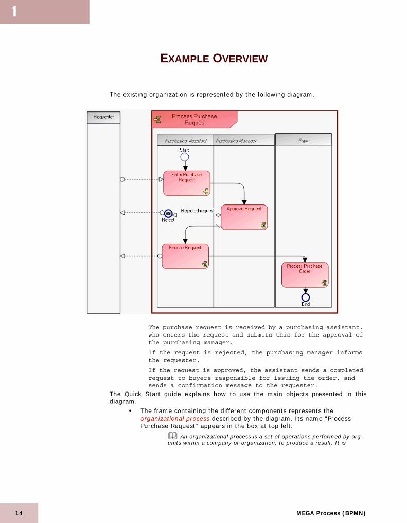
The existing organization is represented by the following diagram.
The purchase request is received by a purchasing assistant, who enters the request and submits this for the approval of the purchasing manager.
If the request is rejected, the purchasing manager informs the requester.
If the request is approved, the assistant sends a completed request to buyers responsible for issuing the order, and sends a confirmation message to the requester.
The Quick Start guide explains how to use the main objects presented in thisdiagram.
• The frame containing the different components represents the organizational process described by the diagram. Its name "Process Purchase Request" appears in the box at top left.
An organizational process is a set of operations performed by org-units within a company or organization, to produce a result. It is
MEGA Process (BPMN)

Organizational ProcessesExample Overview
depicted as a sequence of operations, controlled by events and conditions.
• The participants in execution of this process are org-units. They are represented in columns for reasons of diagram readability.
An org-unit represents a person or group of persons participating in the processes or information system of the enterprise. An org-unit can be internal or external to the enterprise. An internal org-unit is an organizational element of enterprise structure such as a management, department, or job function. It is defined at a level depending on the degree of detail to be provided on the organization (as org-unit type). Example: financial management, sales management, marketing department, account manager. An external organization unit is an organization that exchanges flows with the enterprise. Example: customer, supplier, government office.
A participant (org-unit) enables representation of org-units assigned to execution of a group of operations of a process.
See"Using Participants", page 39 for more details on assignment of org-units to participants in the process.
• The different steps in this process are operations. Organization of these steps is described by sequence flows.
An operation is an elementary step in an organizational process executed by an org-unit. It cannot be broken down. An operation can be industrial (manufacturing a component), logistical (receiving a delivery), or can involve information processing (entering an order).
• Message flows enable representation of data or information circulating between a process and the exterior.
A message flow is information flowing within an enterprise or exchanged between the enterprise and its business environment. A message flow can carry a content.
Evolutions in the business process concern improvement of the following points:
• The time taken to process the request, by reducing the number of purchase requests submitted for purchasing manager approval.
• Profitability, by reorganizing order processing. • Pooling business processes, by considering use contexts. • Flexibility, by identifying org-units involved in the process and their
replacements on critical operations.
15
16
1
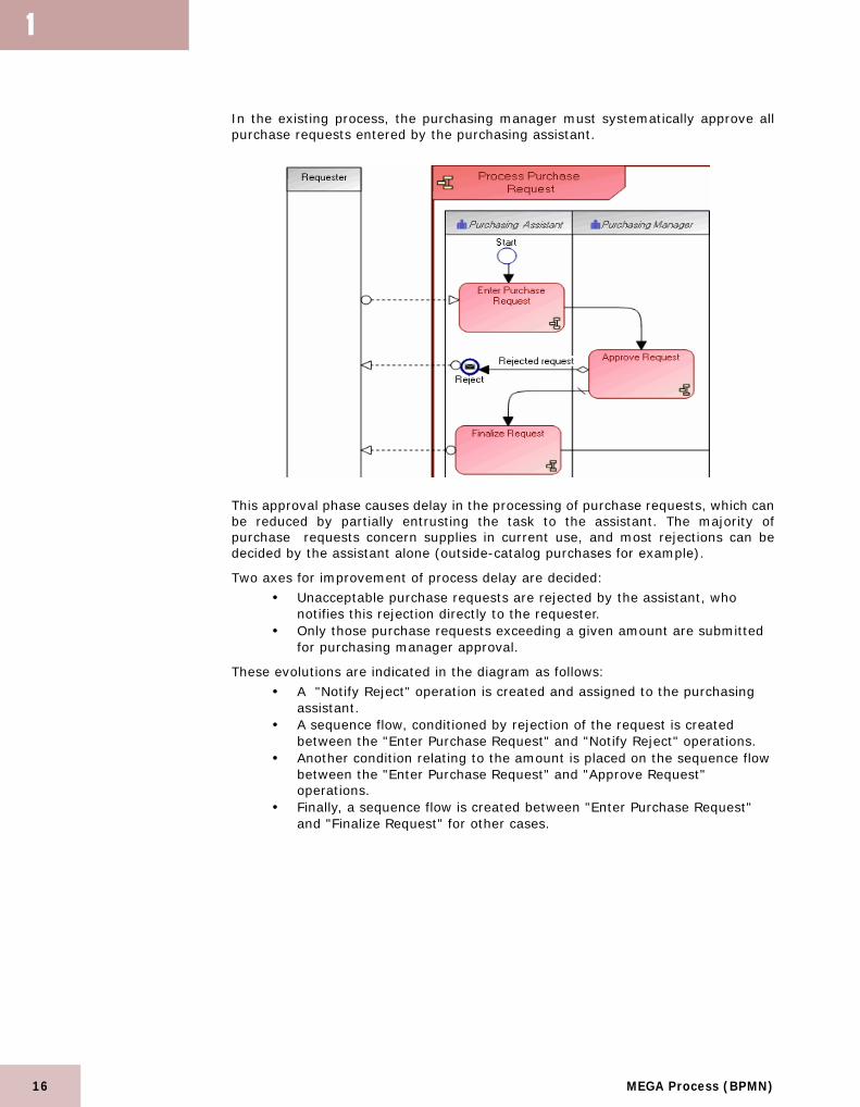
In the existing process, the purchasing manager must systematically approve allpurchase requests entered by the purchasing assistant.
This approval phase causes delay in the processing of purchase requests, which canbe reduced by partially entrusting the task to the assistant. The majority ofpurchase requests concern supplies in current use, and most rejections can bedecided by the assistant alone (outside-catalog purchases for example).
Two axes for improvement of process delay are decided:
• Unacceptable purchase requests are rejected by the assistant, who notifies this rejection directly to the requester.
• Only those purchase requests exceeding a given amount are submitted for purchasing manager approval.
These evolutions are indicated in the diagram as follows:
• A "Notify Reject" operation is created and assigned to the purchasing assistant.
• A sequence flow, conditioned by rejection of the request is created between the "Enter Purchase Request" and "Notify Reject" operations.
• Another condition relating to the amount is placed on the sequence flow between the "Enter Purchase Request" and "Approve Request" operations.
• Finally, a sequence flow is created between "Enter Purchase Request" and "Finalize Request" for other cases.
MEGA Process (BPMN)

Organizational ProcessesExample Overview
In the organizational process diagram, modifications are indicated below bynumbers.
To implement these modifications, you will:
• (1) Create an operation.• (2) Move a sequence flow.• (3) Create a sequence flow and define a condition.• (4) Define a default sequence flow.
Points described here are also presented in the Quick Start guide.
17

18
1
DEFINING AN OPERATION
An operation is a step in a process.
An operation is an elementary step in an organizational process executed by an org-unit. It cannot be broken down. An operation can be industrial (manufacturing a component), logistical (receiving a delivery), or can involve information processing (entering an order).
You will create an operation and connect it to the org-unit responsible for itsexecution.
To create an operation:
1. Click the Operation button and click in the diagram within the shape of the participant responsible for its execution, the "Purchasing Assistant".The Create Operation dialog box opens.
2. Enter the name of the operation in the Name text box, for example “Notify Reject”.
3. Click the OK button.The operation appears in the diagram.
For more information on properties of processes and operations, see "Specifying System Process Behavior" in "System Processes".
MEGA Process (BPMN)

Organizational ProcessesConditioning a Sequence Flow
CONDITIONING A SEQUENCE FLOW
A sequence flow is a directional link that represents chronological organization ofthe different processing steps.
A sequence flow is used to show the order in which steps of a process will be performed. Each sequence flow has only one source and only one target.
Creating a Sequence FlowTo create a sequence flow:
1. Click the Sequence Flow button.
2. Click the first object representing the start step, for example the "Enter Purchase Request" operation and, holding the mouse button down, draw a line to the object representing the next step, in this case the "Notify Reject" operation.
Moving Sequence FlowsYou may need to change the predecessor or successor of a sequence flow. Forexample, you can specify the "Notify Reject" operation as successor of the "ApproveRequest", replacing the "End" event.
To move a sequence flow:1. Click the sequence flow:.
The two link ends are marked with red squares.2. Holding the <Shift> key down, position the mouse on the red square at
the end you wish to move.A reel appears when you are correctly positioned on the link end.
3. Still holding the <Shift> key down, click the square and, holding the mouse button down, move it to its new predecessor or successor before releasing the mouse button.The link appears in its new position in the diagram.
Defining a Condition on a Sequence FlowTo define a condition on a sequence flow, for example on a sequence flow betweenoperations "Enter Purchase Request" and "Notify Reject" :
1. Right-click the sequence flow between the "Enter Purchase Request" and "Notify Reject" operations and in the pop-up menu that appears, select Properties.
19

20
1
2. In the dialog box that appears, select the Characteristics tab.
3. Click the arrow at the right of the Sequence Type box.4. Select "Conditioned" in the drop-down list.5. Enter the conditioning expression in the Predicate text box.6. Click OK.
The text associated with the condition appears on the link which thentakes form .
In the same way you can describe the condition relating to the amount of therequest associated with the sequence flow to the "Approve Request" operation.
Defining a default condition on a sequence flowIf several conditioned sequence flows are from the same operation, you can specifythat one of these should be used as default. For example, having completed the"Enter Purchase Request" operation, the assistant always executes the "FinalizeRequest" operation, except if the request is not acceptable and is below a givenamount.
To define that a sequence flow is used by default:1. Right-click the sequence flow between "Enter Purchase Request" and
"Finalize Request" operations and in the pop-up menu that appears, select Properties.
2. In the dialog box that appears, select the Characteristics tab.3. Click the arrow at the right of the Sequence Type box.4. Select Default in the drop-down list.5. Complete the Predicate text box if you wish to add a comment.6. Click OK.
The link then takes form .
MEGA Process (BPMN)

Organizational ProcessesDefining Message Flows
DEFINING MESSAGE FLOWS
The content of message flows exchanged with the exterior can be specified.
Defining Message Flow ContentYou will specify the content of message flows exchanged between the "ProcessPurchase Request" process and the exterior.
A message flow is information flowing within an enterprise or exchanged between the enterprise and its business environment. A message flow can carry a content.
To define content of a message flow:1. Right-click the message flow and select Properties.
The properties dialog box opens.2. Select the Characteristics tab.3. Click the arrow at the right of the Content text box and select List
Content in the drop-down list.The list of contents of the library appears in the dialog box.
21

22
1
4. Select the name of the content, for example "Purchase Request" and click OK.
A content can be used by several message flows, since it is not associated with a sender or recipient.
The name of the content appears in the diagram.
Creating a Message Flow With ContentYou can specify the content of message flows exchanged between a process and itsenvironment directly at flow creation.
A message flow is information flowing within an enterprise or exchanged between the enterprise and its business environment. A message flow can carry a content.
To create a message flow and its content:1. In the diagram insert toolbar, click the Message Flow button arrow,
option Message Flow With Content.
2. Click the first object representing the start step, and, holding the mouse button down, draw a line to the object representing the next step.The Creation of Message Flow With Content dialog box opens.
3. In the Content drop-down list, select the content you wish to associate with the flow. The message flow and its content are displayed in the diagram.
You can associate several contents to the message flow; see paragraph "Defining Message Flow Content".
MEGA Process (BPMN)

Organizational ProcessesUsing an Organizational Process
USING AN ORGANIZATIONAL PROCESS
An organizational process is a set of operations performed by org-units within acompany or organization, to produce a result. It is depicted as a sequence ofoperations, controlled by events and conditions.In the initial "Process Purchase Request" process, the "Process Purchase Order"operation is executed by a buyer.
In the new organization, "Process Purchase Order" becomes an organizationalprocess in which the Purchasing Manager is involved for:
• Restocking.• Supplier contract negotiation.
The diagram takes a new form.
Using an Existing Organizational Process To more closely detail behavior of a processing step such as an operation, you mustreplace it by an organizational process.
23

24
1
To use an existing organizational process:
1. Click the Organizational Process button and click in the diagram
outside the frame of the described process. The Add Organizational Process dialog box opens.
2. Click the arrow at the right of the Organizational Process text box and select List Organizational Process in the drop-down list.The list of organizational processes in the library appears in a dialog box.
3. Select the organizational process that interests you, for example "Process Purchase Order".
4. Click the OK button.5. Click the Finish button in the Add Organizational Process dialog box.
The organizational process appears in the diagram.In this context, you can move the "Buyer" participant to position it outside the"Process Purchase Order" frame. The "Process Purchase Order" business processremains positioned within this participant.
Accessing an Organizational Process DiagramTo access an organizational process diagram:
1. Right-click the process, in this case "Process Purchase Order", to open its pop-up menu.
2. Select Organizational Process Diagram.
The diagram opens in a new window.
If the process does not have a diagram, you can create it by clicking New in its pop-up menu.
MEGA Process (BPMN)

Organizational ProcessesUsing an Organizational Process
The "Process Purchase Order" organizational process diagram is shown below.
The purchase request is analyzed by the purchasing manager, who checks productavailability and requests that the product be made available.The purchasing manager also checks stock, and if this is insufficient, requests abuyer to send a supplier order.Finally, based on current contracts, the buyers send orders to suppliers.
25

26
1
USING DATA OBJECTS
In an organizational process diagram, a data object can be used to represent thefact that data or objects (correspondence, raw materials, finished products, etc.)are in stock awaiting use. In the example of the "Process Purchase Order" process, data relating to stock isrepresented by the "Stock Data" data object.
A data object is used to explain how documents, data, and other objects are used and updated during the process. A data object can represent an electronic document, or any other type of object, electronic or physical.
Creating a Data ObjectTo create a data object:
1. In the diagram insert toolbar, click the Data Object button
2. Click in the diagram to position the object.The Create Data Object dialog box appears.
3. Click the arrow at the right of the Content text box and select List Content in the drop-down list.The list of contents of the library appears in the dialog box.
4. Select the content, "Contract Data", and click OK.
A content can be used by several data objects.
5. Enter Data Object State if required.
By default the data object carries the same name as its content. The state appears between brackets.
6. Click OK.The data object appears in the diagram.
MEGA Process (BPMN)

Organizational ProcessesUsing Data Objects
Information necessary for execution of operations can be consulted or updated inthe data objects.
To indicate that information was obtained from a data object, for example that stockdata used by the "Analyze Purchase Request" operation was obtained from the"Stock Data" data object:
1. Click the reel in the insert toolbar.
2. Click the data object , for example "Stock Data" and, holding the mouse button down, draw a link to the operation.
Associating a data object with a sequenceYou can also specify that the content of a data object is sent at sequencing of twooperations, for example, a shared object "Purchase Request" can be sent betweenthe operations "Enter Purchase Request" and "Finalize Request".
A data object is used to explain how documents, data, and other objects are used and updated during the process. A data object can represent an electronic document, or any other type of object, electronic or physical.
To simultaneously create a sequence flow and a data object:1. Click the Sequence Flow button arrow, option Sequence Flow With
Data Object.
2. Click the operation representing the start step, and, holding the mouse button down, draw a line to the operation representing the next step.The Creation of Sequence Flow With Data Object dialog box opens.
3. In the Content drop-down list, select the content you wish to associate with the flow. The sequence flow and its content are displayed in the diagram.
Using Data StoresObjects that are shared, supplied or used in processing can be stored in a data store.
A data store provides a mechanism to update or consult data that will persist beyond the scope of the current process. It enables storage of input message flows, and their retransmission via one or several output message flows.
27

28
1
In the example of the "Process Purchase Order" process, data relating to suppliersis represented by the "Supplier Data" data store.
To create a data store:
1. In the insert toolbar, click the Data Store button.
2. Click in the diagram to position the object.The Add Data Store dialog box appears.
3. Enter the name of the data store.4. Click OK.
You can specify the content of message flows exchanged between the data storeand the process by creating message flows in your diagram.
For more details on message flows, see paragraph "Defining message flows".
A message flow is information flowing within an enterprise or exchanged between the enterprise and its business environment. A message flow can carry a content.
MEGA Process (BPMN)

Organizational ProcessesUsing Gateways
USING GATEWAYS
The following example presents a case in which processing progress is conditioned:following analysis of a purchase request, the process either ends, or an order is sentto a supplier.
To specify that several processing steps are accessible following a particularprocessing step, you can use a gateway.
Gateways are modeling elements that are used to control how sequence flows interact as they converge and diverge within a process.
Conversely, you can also use a gateway to indicate that a particular processing step is available from several processing steps of a process.
For more information on gateways, see "Gateways", page 68.
29

30
1
PLACING A PROCESS IN ITS CONTEXT
The "Process Purchase Request" and "Process Purchase Order" processes complywith the general process of standard purchasing, operation of which is described bythe following diagram:
Purchase requests are processed by the purchasing department. If the request isrejected, a notification is sent to the requester, otherwise the validated request isprocessed within the framework of the "Process Purchase Order" process.If stock level drops below a minimum level, an order is sent to the supplier andproducts are received by the logistics department.When available, the product is made available to the requester by the logisticsdepartment.
MEGA Process (BPMN)

Organizational ProcessesPlacing a Process in its Context
Creating an Organizational Process in a DiagramTo create a process from a process diagram that is already open:
1. Click the Organizational Process button in the diagram objects toolbar
2. Click within the frame of the described organizational process and within the frame of the participant responsible for this process.The Add Organizational Process dialog box opens.
3. Enter the organizational process name.4. Click Finish.
The new process appears in the diagram.
Calling an Organizational Process in an OperationYou can create an operation that calls an organizational process. This functionalityenables, for example, replacement of the process called by another process withoutdisturbing description of the main process.
To create an operation that calls an organizational process:
1. Select the Operation button and select Organizational Process Call.
2. Click in the diagram within the shape of the participant responsible for its execution.The Creation of Organizational Process Call dialog box opens.
3. In theOrganizational Process box, enter the name of the process called, for example "Process Purchase Request", that could be replaced by "Process Urgent Purchase Request".
By default, the operation carries the same name as the organization process called.
4. Click the OK button.The operation appears in the diagram with the name of the organizationalprocess.
31

32
1
Initializing an Organizational Process DiagramIf you create the diagram of an organizational process in a particular context, suchas "Make Available" in the example, and you selected the Diagram initializationoption before clicking Create in the organizational process diagram creationwindow, the new diagram that opens will be as follows.
The diagram is initialized with:
• A participant representing the recipient of message flows exchanged by the process with the exterior.
• The message flows themselves as described in the different use contexts of the described process.
• An event of intermediate type for each sequence flow triggering or triggered by the process.
• An end event for each sequence flow, triggered by the process, leading to another end event.
MEGA Process (BPMN)

Organizational ProcessesDefining Process Events
DEFINING PROCESS EVENTS
The events enabling representation of facts occurring during process execution.
An event represents a fact occurring during execution of a process, for example a new contract concluded with a supplier. An event marks the impact on process progress of a phenomenon internal or external to the process. There are different natures of events: start events, catch events, throw events and end events.
Events can be used:
• Within a process to define facts internal to the process.• Outside a process to describe causes and effects of events of the process
depending on its use context.The different event types are presented in this section.
Creating an eventTo create an event:
1. Click the Event button in the insert toolbar.2. Click in the diagram.
The Create Event dialog box opens.3. Enter the name you wish to give the event.
You can directly click the Finish button of the wizard. A catching event without type is created.
4. Select the nature of new event.
By default, the nature is Catching.
5. Click Next and select the type of event you wish to create.
By default the type is None.
6. Click Finish.The new event appears in the diagram. The shape of the event respectsconventions linked to its type and nature.
You can directly create the most frequently used events: 1. Click the Events button in the toolbar and select from the predefined
events that which interest you.
2. Click in the diagram.The new event appears in the diagram.
33

34
1
Event naturesThe nature of the event enables specification of its position in the processing.
• Start: start of the processing sequence• Catching: awaiting an event (arrival of a message, signal, etc.) before
continuation of processing• Throwing: triggering an event (message, signal, etc.) and continuation
of processing• End: end of the processing sequence
Event typesEvent type enables specification of what will trigger the event and what will betriggered by the event.
• None: the trigger is not specified, generally at the start or end of a process
• Message: the event is receiving or sending messages• Timer: the event is triggered by a timer• Error: the event is triggered by errors or throws errors that cause
interrupt of the process• Cancel: the event reacts to cancelled process steps or triggers
cancellation• Compensation: the event handles or triggers compensation of a failed
process• Conditional: the event is triggered by a condition• Link: the event is used to connect two sections of a process• Signal: the event waits for a signal or throws a signal. One signal
thrown can be caught multiple times• Terminate: the event indicates that all process steps should be
immediately ended without compensation or event processing• Multiple: the event has multiple triggers• Escalation : the event is triggered by an error or throws a non-critical
error
MEGA Process (BPMN)

Organizational ProcessesDefining Process Events
Event type and nature combinationsThe following table presents valid combinations of event type and nature.
Connecting Events to Sequence FlowsIn a given context, a process can be connected to another process by a sequenceflow.
In the example above, the "Process Purchase Request" process precedes the "Process Purchase Order" process.
35

36
1
When this latter process is described by a diagram, the process that precedes it canbe shown.
In the diagram that describes the "Process Purchase Order" process, the "Process Purchase Request" process that precedes it is shown.
Showing external processes.
To do this, it is necessary to specify the event involved in the sequence flow:1. Right-click the sequence flow and select Properties.
The properties dialog box opens.2. In the Characteristics tab, consider the Triggering Event and
Triggered Event sections.
From this dialog box, it is possible to open diagrams containing these events via the pop-up menu of the process that owns them (Owner Element).
MEGA Process (BPMN)

Organizational ProcessesDefining Process Events
3. In the Triggered Event section, click the Connect button.The Select Query dialog box opens.
4. Click Possible Triggered Event.The list displayed proposes start events or catching events of thesuccessor process.
The successor process is generally triggered at its start and normally has only a single start event. This start event is therefore generally the event that interests you.
5. Select the event corresponding to the sequence flow.6. Click OK.
If you open the organizational process diagram containing this event, you can viewthe process that precedes it. You can similarly select the triggering event of the previous process. In this case,end events or throw events from the preceding process will be proposed.
Accessing Preceding or Succeeding ProcessesIn the organization of the standard purchase process, the "Process Purchase Order"organizational process is activated after processing of the purchase request, anditself activates the "Make Available" process. To show, at events level, the processes preceding and succeeding the describedprocess, you must:
• Specify the sequence flows in which the events are involved. • Activate the views enabling access to context-sensitive information.
To activate the context-sensitive view:
1. Click the Views and Details button in the diagram toolbar.
2. Select the View External Processes check box.3. Click OK.
37

38
1
Attaching an Event to a ProcessTo attach an event to a process:
1. Click the event and hold the mouse button down.2. Position the event on the border of the process.
The border of the process is highlighted.
To detach the event from the process border:
Right-click the event and select Detach.
MEGA Process (BPMN)
Organizational ProcessesUsing Participants
USING PARTICIPANTS
A participant enables:
• Assignment of a group of operations to one or to several enterprise org-units.
• Representation of a unit external to the process with which the process communicates by means of message flows.
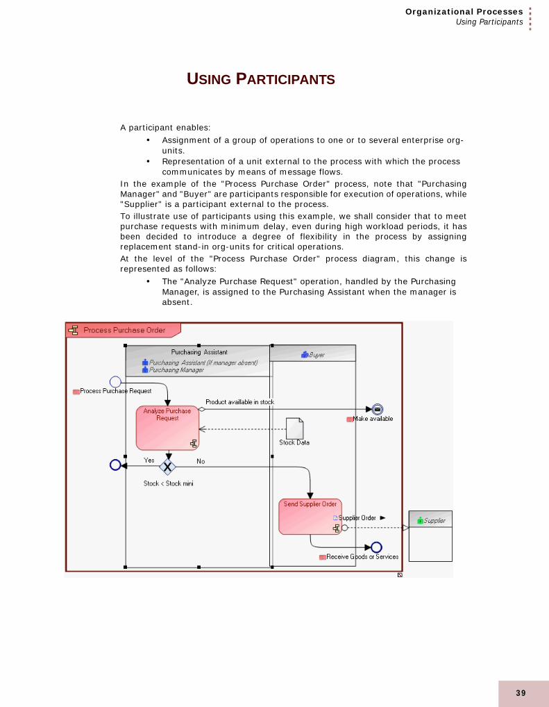
In the example of the "Process Purchase Order" process, note that "PurchasingManager" and "Buyer" are participants responsible for execution of operations, while"Supplier" is a participant external to the process.To illustrate use of participants using this example, we shall consider that to meetpurchase requests with minimum delay, even during high workload periods, it hasbeen decided to introduce a degree of flexibility in the process by assigningreplacement stand-in org-units for critical operations.At the level of the "Process Purchase Order" process diagram, this change isrepresented as follows:
• The "Analyze Purchase Request" operation, handled by the Purchasing Manager, is assigned to the Purchasing Assistant when the manager is absent.
39

40
1
Creating an Org-Unit ParticipantTo create an org-unit from a new participant:
1. Click the arrow on the right of the Participant button in the insert toolbar, and in the drop-down list select Participant (Org-Unit).
2. Click in the diagram workspace within the organizational process frame. The Create Participant (Org-Unit) - Assignments dialog box opens.
3. To create an org-unit from this participant, enter the name of the new org-unit in the Org-Unit text box.
4. Indicate the name of the participant if you wish to specify the org-unit role in the process.
5. Click the Finish button.The participant is positioned in the diagram. If you have not specified aname, it will carry the name of the assigned org-unit.
☺ To hide the name of the participant, open its pop-up menu and select Shapes and Details. In the tree on the left, click the "Short Name" folder, then in the Content tab, clear the Short Name check box.
Assigning Several Org-Units to a ParticipantOrg-units, either new or already created, can be assigned to participants of aprocess.
To assign an org-unit to a participant:1. Right-click in the grey title bar of the participant.
MEGA Process (BPMN)

Organizational ProcessesUsing Participants
2. Open the pop-up menu of the "Purchasing Manager" participant in the example and select Properties.
The properties dialog box opens.3. In the Characteristics tab, Assignment section, click the Connect
button.The query dialog box opens.
4. Select Org-Unit and click Find. The list of existing org-units is displayed.
5. Select the org-unit you wish to assign to the "Purchasing Assistant" participant in the example, and click OK.A new assignment appears in the properties dialog box of the participant.
6. Click Close.Names of assigned org-units appear in the title bar of the participant withthe name of the participant.
To condition participation of an org-unit:1. Open the participant properties dialog box.2. In the Characteristics tab, select the line of the actor of which you wish
to condition assignment.
41

42
1
3. Click in the Conditioning column.
4. Enter the text of the condition.5. Click Close to close the participant properties dialog box.
The text of the condition appears between brackets alongside the nameof the org-unit in the participant title bar.
MEGA Process (BPMN)

Organizational ProcessesImproving Presentation
IMPROVING PRESENTATION
Adding Notes to ObjectsYou can add notes in a diagram and connect these to an object.
To create a note and connect it to an object (for example an operation):
1. Click the Note button.
2. Click in the diagram.The Add Note dialog box opens.
3. Indicate the Name and Type of the note.
The note Name is automatically generated by MEGA and does not haveany special meaning.You can choose different types of note: "Correction", "Documentation","Improvement", "Example", "Question", "Remark", etc.
4. Select for example "Remark" type and enter your note in the text box.
5. Click the Link button and connect the note to the operation.
43
44
1
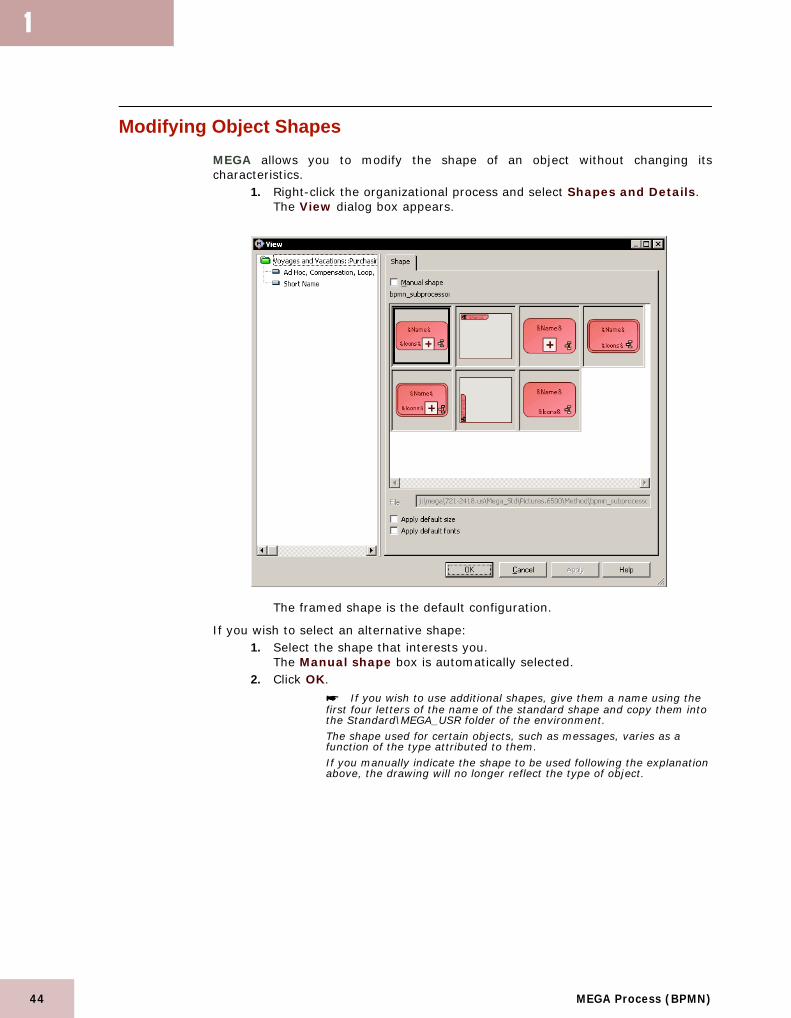
Modifying Object ShapesMEGA allows you to modify the shape of an object without changing itscharacteristics.
1. Right-click the organizational process and select Shapes and Details.The View dialog box appears.
The framed shape is the default configuration.
If you wish to select an alternative shape: 1. Select the shape that interests you.
The Manual shape box is automatically selected.2. Click OK.
If you wish to use additional shapes, give them a name using the first four letters of the name of the standard shape and copy them into the Standard\MEGA_USR folder of the environment.The shape used for certain objects, such as messages, varies as a function of the type attributed to them. If you manually indicate the shape to be used following the explanation above, the drawing will no longer reflect the type of object.
MEGA Process (BPMN)

Organizational ProcessesImproving Presentation
Modifying Object Name PresentationMEGA enables modification of presentation of character strings associated with theobject shape. You can for example display the predicate of a sequence flow onseveral lines.
To modify presentation of character strings associated with the object shape.1. Right-click the object and select Shapes and Details.
The View dialog box appears.2. At the left of the View dialog box, select the character string of which you
wish to modify presentation.The View dialog box is updated.
3. In the Content tab, confirm that the check box on the right of character string name is selected.
If this box is not selected, the name will be masked in the diagram.
4. Select the Font tab.The View dialog box is updated to present all available display options.
45

46
1
5. Select the options that interest you.6. Click OK.
Formatting LinksThe "Edit" toolbar at the right of the diagram enables formatting of links.
If this toolbar is not displayed by default:1. Select View > Toolbars > Edit.
This toolbar now appears on your workspace. 2. Select each link then click the button corresponding to the desired line
style (simple, orthogonal, curved, double):
☺ You can also select a link, hold down the <Ctrl> key, and then move this link. A "nail" now appears on the link allowing you to give it the desired form.
3. Save and close your diagram.
Changing FontsTo configure the font of the text displayed.
1. Select the text.2. In the menu bar, select Format > Font.
A dialog box appears. You can select another font or font size in this dialog box.
Refining Flowchart AppearanceMEGA allows you to add graphics to improve the appearance of your flowchart. Inthe diagram:
1. Click the Basic Drawing Object button
The dialog box proposing different standard shapes opens.
MEGA Process (BPMN)

Organizational ProcessesImproving Presentation
2. Select the Shape.A window similar to that below appears.
3. In the folder in which you installed MEGA, open sub-folder MEGA_STD\Pictures.6500\Art.
4. Select a shape and click Open. The shape then appears in the drawing.
☺ You can create your own custom shapes or use images from other software. For more information on creating new shapes, see the online help or the Advanced guide.
47

48
1
MEGA Process (BPMN)

2
BUSINESS PROCESSES
This chapter presents how to describe products or services supplied by processes of the enterpriseto its customers.
The business process diagram enables representation of product or service offerings proposed bythe enterprise to each of its markets, as well as the processes that produce these.
MEGA enables creation and definition of enterprise business processes.
"Creating a Business Process", page 50"Representing Product Offerings", page 51"Representing Process Contextualization", page 53
49

50
2
CREATING A BUSINESS PROCESS
To create a business process from the navigator:
A business process represents a system that offers products or services to an internal or external client of the company or organization. At the higher levels, a business process represents a structure and a categorization of the business. It can be broken down into other processes. The link with organizational processes will describe the real implementation of the business process in the organization. A business process can also be detailed by a functional view.
1. Right-click the current library. 2. Select New > Business Process.
The Create Business Process dialog box appears.3. Enter the name of the business process in the Name box.
4. Click OK.The business process is created and added to the list of business processes.
The OK button is grayed if the Name box is not completed.
In MEGA, business processes are described by diagrams.
Creating a Business Process DiagramTo create a business process diagram:
1. Right-click the business process name and select New > Diagram.
2. In the dialog box that opens, select "Business Process Diagram and click the Create button.The diagram window opens.
MEGA Process (BPMN)
Business ProcessesRepresenting Product Offerings
REPRESENTING PRODUCT OFFERINGS
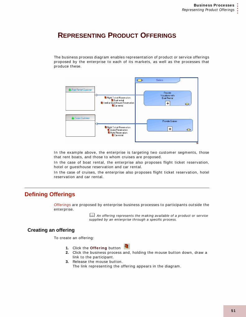
The business process diagram enables representation of product or service offeringsproposed by the enterprise to each of its markets, as well as the processes thatproduce these.
In the example above, the enterprise is targeting two customer segments, thosethat rent boats, and those to whom cruises are proposed.In the case of boat rental, the enterprise also proposes flight ticket reservation,hotel or guesthouse reservation and car rental.In the case of cruises, the enterprise also proposes flight ticket reservation, hotelreservation and car rental.
Defining OfferingsOfferings are proposed by enterprise business processes to participants outside theenterprise.
An offering represents the making available of a product or service supplied by an enterprise through a specific process.
Creating an offeringTo create an offering:
1. Click the Offering button 2. Click the business process and, holding the mouse button down, draw a
link to the participant. 3. Release the mouse button.
The link representing the offering appears in the diagram.
51

52
2
Defining offering productsA product represents commodities offered for sale, either goods or
merchandise produced as the result of manufacturing, or a service, ie. work done by one person or group that benefits another.
To specify detail of offerings of products:1. Right-click the offering and select Properties.
The properties dialog box opens.2. Select the Characteristics tab.3. Click the New button in the Products section and enter the name of the
product in the field that appears.4. Select the name of the product, then click OK.
The name of the product appears in the diagram.
A product can be broken down into component products from its properties dialog box or from the navigator.
Initializing the business process diagramIf you create the diagram of a business process in a particular context, such as"Provide Vacations with Boat Rental" in the example, and you selected the Diagraminitialization option before clicking Create in the business process diagramcreation window, the new diagram that opens will be as follows.
The diagram is initialized with:
• A participant representing the recipient of products exchanged by the process with the exterior.
• The products themselves, described by message flows and with contents corresponding to the products of service offers associated with the described process.
• A start event and an end event.
MEGA Process (BPMN)
Business ProcessesRepresenting Process Contextualization
REPRESENTING PROCESS CONTEXTUALIZATION
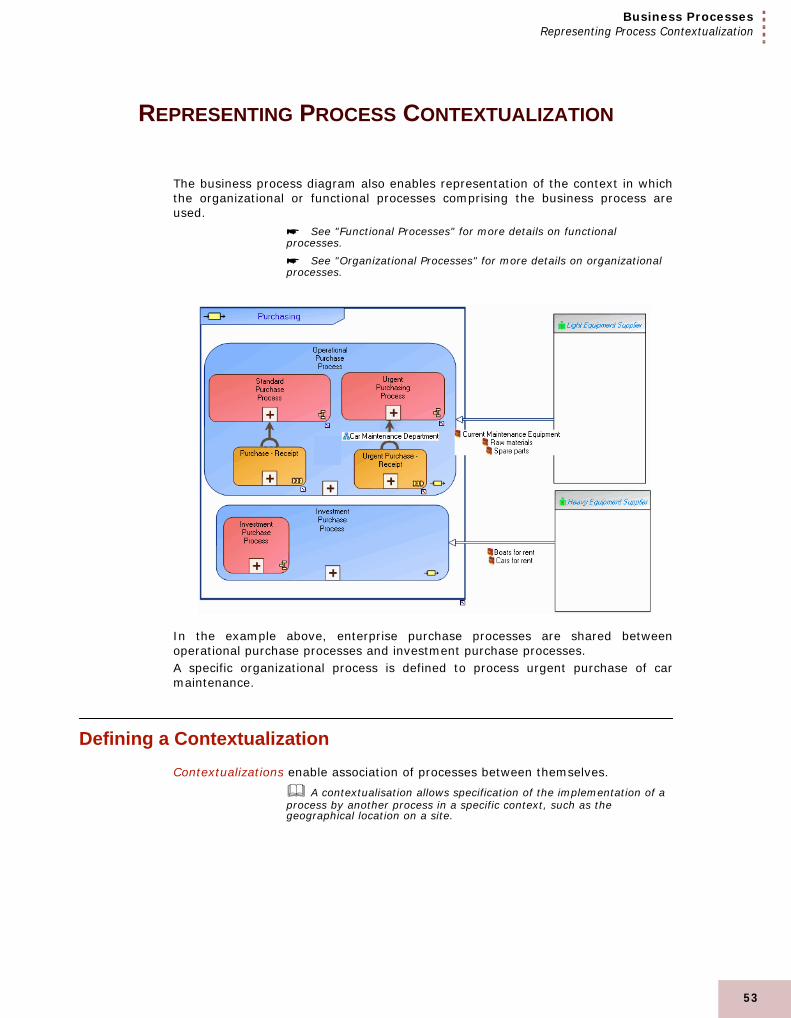
The business process diagram also enables representation of the context in whichthe organizational or functional processes comprising the business process areused.
See "Functional Processes" for more details on functional processes.
See "Organizational Processes" for more details on organizational processes.
In the example above, enterprise purchase processes are shared betweenoperational purchase processes and investment purchase processes.A specific organizational process is defined to process urgent purchase of carmaintenance.
Defining a ContextualizationContextualizations enable association of processes between themselves.
A contextualisation allows specification of the implementation of a process by another process in a specific context, such as the geographical location on a site.
53

54
2
Creating a contextualizationTo create a contextualization:
1. Click the Contextualization button 2. Click the process to be implemented and, holding the mouse button
down, draw a link to the process describing implementation. Release the mouse button.The link representing the contextualization appears in the diagram.
Defining contextTo specify the context in which a process implements another process:
1. Right-click the contextualization and select Properties.The properties dialog box opens.
2. Select the Characteristics tab.3. Click the Connect button in the Implementation Context section.4. Enter the context type, org-unit or site, in the dialog box that opens.5. Click the Find button.6. In the list that appears, select the org-units or sites concerned and click
OK.7. Click the Close button.
The implementation contexts appear in the diagram.
MEGA Process (BPMN)

3
FUNCTIONAL PROCESSES
This chapter presents why and how to describe value chains of the enterprise in the form offunctional processes.
When an enterprise operates out of numerous geographical locations, organization of businessprocess operations can vary significantly between regions.
It is therefore useful to have a summary view, independent of organizational structure, to representsteps in the value chain connected to enterprise business and common to all organizational variants.
A functional representation of the value chain also facilitates improvement in enterprise operation.
When the operation of each organizational process is represented, this enables local optimization ofeach process as explained in the previous chapter.
This structure however remains partitioned by existing organizational structures. More significantchanges require a broader view of the value chain, independent of organization. This global view isrepresented by the functional process diagram.
MEGA enables the creation and description of enterprise value chains.
"Creating a Functional Process", page 56"Representing a Functional Process", page 57
55

56
3
CREATING A FUNCTIONAL PROCESS
To create a functional process from the navigator:1. Right-click the current library. 2. Select New > Functional Process.
The Create Functional Process dialog box appears.3. Enter the name of the functional process in the Name box.
4. Click Finish.The functional process is created and added to the list of functional processes in themenu tree.
The Finish button is grayed if the Name box is not completed.
MEGA Process (BPMN)
Functional ProcessesRepresenting a Functional Process
REPRESENTING A FUNCTIONAL PROCESS
Highlighting organizational choicesEach enterprise has activities related to its business that must be performedwhatever the organization in place. These activities can be purchasing, sales, salesadministration, manufacturing, etc.Defining their organization consists of assigning these activities to the org-units thatwill perform them.We can distinguish between:
• Processes relating to the business of the enterprise: these are difficult to change unless the enterprise decides to totally review its business.
• Processing depending on organizational choices.
Diversity of variantsMost variants of a process are the result of organizational choices such as givingpreference to urgent orders, special processing for large or export orders, etc.It is necessary to overcome this diversity in order to move on to a new set ofvariants, for example processing orders via telephone or the Internet. Representinga business process in terms of activities gives a unique representation of the valuechain, highlighting what must be done irrespective of organization choices.
Number of stepsCertain steps in an organizational process are exclusively linked to the chosenorganization. In such cases, it is useful to check whether these steps provide anyreal added value to clients or only concern the way things are done.Delivery times can also be reduced by restructuring the order of these steps.To highlight possible improvements, you can represent a value chain by flowsexchanged between enterprise activities.
A functional activity is a step in a process. This step represents the contribution of a business line to the process value chain.
57

58
3
The following diagram presents a functional process example:
"Purchase-Receipt" functional diagram
The purchase request is recorded and must then be approved. The requester isinformed of approval or rejection of the request. If the request is validated, ananalysis of the required order is carried out. If stock is lower than a given threshold, an order is prepared and sent to the supplierfor resupply.If the product is available, or as soon as it is received from the supplier, it is madeavailable to the requester.
MEGA Process (BPMN)

Functional ProcessesRepresenting a Functional Process
In this diagram, the business functions concerned are represented in columns.
A business function is a skill or grouping of skills of interest for the enterprise.
In the organization previously presented, three org-units: purchasing assistant,purchasing manager and buyer, systematically participate to execute the first foursteps: record and approve the request, analyze and send the order.Optimization of the "Process Purchase Request" organizational process has savedone step: when the total amount of the order is not large, the purchasing assistantis authorized to approve or reject the purchase order.In the case of urgent orders, you can again save steps by authorizing the purchasingassistant to send the order when the amount is not significant.We obtain the following functional process for processing of urgent orders:
"Urgent Purchase-Receipt" functional diagram
The first step consists of analyzing the purchase request. If the total amount islarge, normal processing is carried out.Otherwise, the availability request and a restock request are sent, if necessary. Therest of the functional process is identical to the normal case: when the order hasbeen received, it is made available to the requester.
59

60
3
We can define a new organizational process for processing of urgent purchaserequests, in which responsibilities of the purchasing assistant are extended.
"Process Urgent Purchase Request" Organizational Process
The purchasing assistant begins by analyzing the purchase request. If the amountis large, the normal process purchase request process is implemented. If theproduct is in stock, the assistant sends the make available request.If not, the assistant sends a purchase order to the supplier. The rest of theprocessing is carried out within the framework of the normal "Process PurchaseRequest" organizational process.To analyze the purchase request and send the order, the purchasing assistantrequires data on stock levels. He will have access to the "Equipment Purchasing"application. This new variation of the organizational process enables faster processing for urgentorders. It demands higher qualifications of the purchasing assistant who has moreresponsibilities.
You can show systems used by operations by selecting "System
used" in the window opened from the "Views and Details" button .
A system used during the execution of a step of a process represents what is necessary to realize this step. It can be an application or an IT service, or any other non IT resource, or more generally a functionality.
MEGA Process (BPMN)

4
SYSTEM PROCESSES
MEGA allows you to model the IT system process implemented when using an organizationalprocess. This description is made in a BPMN model detailing the sequence flow of tasks performedwhen executing the application in the particular context.
The BPMN (Business Process Modeling Notation) specification was created to formalize graphicalrepresentation of IT and business processes, offering notation easily used by all participantsconcerned.
The points covered are:
"Managing a System Process", page 62"Tasks", page 65"Sequence Flows, Events and Message Flows", page 66"Gateways", page 68"Processing Step Input Gateways", page 68"Creating a System Process Participant", page 70
61

62
4
MANAGING A SYSTEM PROCESS
A system process represents automated execution of an organizational process.
The system process diagram uses notation proposed by BPMN standard.
Creating a System Process You can create a system process from the navigator or from an organizationalprocess diagram.
A system process is the executable representation of a process. The elements that formalize a system process are the following: the events of the workflow, the tasks to be carried out during the processing, the algorithmic elements used to specify the way in which the tasks follow each other, the information flows exchanged with the participants.
To create a system process from an organizational process diagram:1. Click the Views and Details button in the diagram toolbar.2. Select the Implementation Contexts check box.3. Click OK.
The Contextualization and System Process buttons appear
in the insert toolbar.
4. Click the System Process button in the diagram insert toolbar.5. Click in the diagram where you wish to position the system process.
The Add System Process dialog box opens.6. In the System Process box, enter the name you wish to give your
process.7. Click Finish.
Connecting a System Process to an Organizational ProcessTo specify that an organizational process is implemented by a system process in agiven context, you must create a contextualization link between the two objects.
A contextualisation allows specification of the implementation of a process by another process in a specific context, such as the geographical location on a site.
MEGA Process (BPMN)

System ProcessesManaging a System Process
For example, the "Process Urgent Purchase Request" organizational process isimplemented by the "Analyze Purchase Request" to assure speed and efficiency ofprocessing.
To create a connection between an organizational process and a system processfrom an organizational process diagram:
1. Click the Views and Details button in the diagram toolbar.2. Select the Implementation Contexts check box.3. Click OK.
The Contextualization and System Process buttons appear
in the insert toolbar.
4. Click the Contextualization button in the insert toolbar.
5. Click the organizational process and, holding the mouse button down, drag the cursor to the system process and release the mouse button.The contextualization appears in the diagram.
Creating a System Process DiagramThe system process algorithm can be expressed by sequencing of tasks anddecisions.
63

64
4
ExampleThe diagram below represents purchase request processing.
• A product search is carried out from the referenced products repository.• If the product is new, search for a supplier and comparative study of
prices is carried out. An order is then sent and the process ends.• If the product is referenced, stock is analyzed.• If stock is sufficient, a "Make available" request is activated and the
process ends.• If stock is less than minimum stock, an order is sent to the supplier and
the process ends.
To create a system process diagram:1. Right-click the system process name and select New > Diagram.2. In the window that opens, select System Process Diagram, confirm
that the Diagram initialization check box is selected and click the Create button.The system process diagram window opens.
MEGA Process (BPMN)

System ProcessesTasks
TASKS
Tasks correspond to process steps.
A task is an elementary step that is included within a system process. A task is used when the work in the system process is not broken down to a finer level of the process. Generally, an end-user and/or an IT service are used to perform the task when it is executed.
Creating a task in a system processTo create a task:
1. In the diagram insert toolbar, click the Task button then click in
the diagram.2. Enter the task name and click OK.
The task appears in the diagram.
65

66
4
SEQUENCE FLOWS, EVENTS AND MESSAGE FLOWS
Sequence flowsOrganization of tasks in the system process is represented by sequence flowsbetween tasks.
A sequence flow is used to show the order in which steps of a process will be performed. Each sequence flow has only one source and only one target.
EventsEvents represent facts occurring during process execution.
An event represents a fact occurring during execution of a process, for example a new contract concluded with a supplier. An event marks the impact on process progress of a phenomenon internal or external to the process. There are different natures of events: start events, catch events, throw events and end events.
An example is the start or end of the system process.
Start
Final
The event can also be sending or receiving a message flow.
MEGA Process (BPMN)

System ProcessesSequence Flows, Events and Message Flows
Message flowsMessage flows represent exchanges between the system process and the exterior.
A message flow is information flowing within an enterprise or exchanged between the enterprise and its business environment. A message flow can carry a content.
A message flow can be linked to an event of message type.
67

68
4
GATEWAYS
Complying with BPMN standard, several gateway types are proposed in the diagraminsert toolbar.
Gateways are modeling elements that are used to control how sequence flows interact as they converge and diverge within a process.
To better understand the main use cases, we distinguish output gateways of aprocessing step from input gateways.
Processing Step Output GatewaysIn the case of an Exclusive gateway, only one output branch can be selected fromthose available. The branch can be selected as a function of the Data available forthe process, or of the Events occurring during its execution.
In the case of a Parallel gateway, all output branches are processedsimultaneously.
In the case of a Complex gateway, one or several output branches can be selectedfrom those available.
A Complex gateway represents a combination of those above.
When the gateway has been created, its type can be modified in its properties dialogbox.
At output of a step, a gateway represents a point of divergence of sequence flowsof a process.
Processing Step Input GatewaysAt input of a step, a gateway represents a point of convergence of sequence flowsof a process.
In the case of an Exclusive gateway, the process step is triggered when one ofthese branches is active.
MEGA Process (BPMN)

System ProcessesGateways
In the case of a Parallel gateway, all input branches are processed simultaneously.
Creating a GatewayTo create a gateway:
1. Click the arrow at the right of the Gateway button in the diagram insert toolbar and select the gateway type you wish to create.
2. Click in the diagram.The gateway appears in the diagram with shape appropriate to its type.
Modifying a GatewayTo modify a gateway:
1. Right-click the gateway and select Properties.The properties dialog box opens.
2. In the Characteristics tab, modify the name or type of the gateway.3. Click OK.
To display the name of a gateway, masked by default, see "Modifying Object NamePresentation", page 45.
69

70
4
CREATING A SYSTEM PROCESS PARTICIPANT
In a system process diagram, a participant enables grouping of tasks assigned toan application or service.
To create a participant:1. In the diagram insert toolbar, click the arrow at the right of the
Participant button
2. In the list proposed, select for example Application Participant and click in the diagram.The participant creation dialog box appears.
3. Click the arrow at the right of the Application box, and select List Application.
4. Click Finish.The participant created appears in the diagram with a header containingthe name of the assigned application.
To place a participant with assignment as yet unknown, select the Participant icon.
To assign a task to a participant:
place the task within the frame of the participant.
MEGA Process (BPMN)

System ProcessesSpecifying System Process Behavior
SPECIFYING SYSTEM PROCESS BEHAVIOR
Complying with BPMN standard, a sub-process can have different behaviors.
To describe for example that a system process is executed by a loop:1. Right-click the process and select Properties.
The properties dialog box opens.2. In the Characteristics tab, click the arrow at the right of the Loop box.
A list of loop types appears.3. Select the loop type corresponding to process behavior.4. Click OK.
Shape of the process is modified to display the symbol of the loop.
Behaviors proposed are:
• Transaction: a Transaction is a set of coordinated activities leading to a consistent, and verifiable outcome.
• Loop: a loop is a process step that is repeated as long as a condition is true. • "Do While": the condition is evaluated before the first execution.• "Do Until": the condition is evaluated after the first execution. In this
case, the process step is executed at least once.The predicate enables specification of the loop execution condition.
• Ad Hoc: steps of an ad hoc process are not controlled or sequenced in a particular order. Their performance is determined by the performers of the process.
• Multiple: the process is repeated a number of times that is evaluated only once before it is performed.
• Compensation: a compensation defines the set of activities that are performed during the roll-back of a transaction to compensate for activities that were performed during the normal flow of the process.
Compensation descriptionCompensation is caused by an event occurring during process execution. This eventis placed at the edge of the interrupted process. It can be moved along the edge ofthe process.
71

72
4
To free the event from the process, use the detach command in its pop-up menu.
This event can trigger a compensation operation.
For reasons of consistency and simplification, the compensation link is represented in MEGA by a sequence flow. BPMN standard proposes a specific link.
MEGA Process (BPMN)

5
ORGANIZATIONAL CHARTS
MEGA enables representation of enterprise structure It indicates the hierarchy of org-units in theenterprise, specifies the persons that play the role of these org-units, and shows at which site theorg-unit is located.
"Creating an Organizational Chart", page 74"Drawing an Organizational Chart", page 75
73

74
5
CREATING AN ORGANIZATIONAL CHART
MEGA Process allows you to design your organizational charts using the same toolsand methods as applied to processes.MEGA Process organizational charts contain the following descriptive objects:
• Org-Units, which are generally elements defining the enterprise structure, such as Sales Department.
• Persons such as Ms. Brown, Mr. Smith, etc.• Sites that are geographical locations pivotal to the organization, such as
headquarters, plants, etc.
To create an organizational chart:1. In the workspace, select the Main Objects navigation window.
The Main Objects window is accessed by selecting View > Navigation Windows > Main Objects.
2. Right-click an org-unit and select New > Diagram.
3. In the diagram creation wizard, click Org-Unit Organizational Chart then Create.
The corresponding organizational chart opens. It is automatically initialized with thecomponent org-units of the described org-unit.
MEGA Process (BPMN)

Organizational ChartsDrawing an Organizational Chart
DRAWING AN ORGANIZATIONAL CHART
An organizational chart provides an overview of the enterprise structure. Theobjects described in an organizational chart are:
• Org-Units.• Persons.• Sites.
Querying objectsCreate, for example, the "Shipping Department" organizational chart.
To simultaneously add all the org-units involved in your processes that were notautomatically inserted at diagram initialization:
1. In the diagram objects toolbar, click button then click in the
diagram.2. In the Add Org-Unit dialog box, Select Query in the drop-down list.3. In the dialog box that appears, click the Find button.
The result dialog box appears.4. Select the org-units "Stock Manager", "Finished Products Storage",
"Sales Management", "Stock Management" and "Transportation Service" holding down the <Ctrl> key.
☺ When you click on an object while holding down the <Ctrl> key, you add it to the list of selected objects if it was not previously selected, or you remove it from the selection if it was.
75

76
5
5. Drag-and-drop the selected objects from the result dialog box into the diagram.
You may keep your search results in order to reuse them later. To do this, click button Keep result in new window.
☺ To exit org-unit creation mode, click the Esc button.
Rearrange your organizational chart so that it looks like this:
☺ You can select several objects in the diagram. To do this, hold down the <Shift> key while clicking on each object you wish to select. You can also use the mouse to drag a rectangle around the desired objects.You can assign the same size to several objects by selecting them and then applying the Make Same Size command in the Drawing menu. Follow the same steps to align objects: from the Drawing menu, select Align object. Note that the last object selected is used as the reference.If you perform an action that you want to cancel, select Edit > Cancel.
6. You will now add the sites where the org-units are located.
A site is the geographical location of an organization. Examples: Boston subsidiary, Seattle plant, and more generally the headquarters, subsidiaries, plants, warehouses, etc.
7. Double-click the Site button in the toolbar and successively add the sites "Subsidiary", "Sales Office" and "Warehouse".
8. Draw the links between these objects.Note that certain links might already exist.
MEGA Process (BPMN)

Organizational ChartsDrawing an Organizational Chart
When you create a link between two org-units, always drag from the org-unit higherin the hierarchy down to the subordinate. Once the link is drawn, an arrowheadindicates the direction of the hierarchy.
☺ The name of the org-unit connected to a person is considered as the job title of that person and is used in the document modification history.
You can also add persons using the Person button.
A person holds a position in an organization. He or she is designated by name. Example: Mr. Smith.
If the Person button does not appear in the toolbar, add it by selecting it in the Views window.
Specifying the properties of an org-unitTo specify the properties of an org-unit:
1. Right-click the org-unit.2. Select Properties.
☺ When an org-unit appears in a diagram, you can describe it with a new organizational chart using its pop-up menu.
77

78
5
3. In the Org-Unit-Type list box, select the org-unit type.
There are several types of org-unit:
• A "Manager" org-unit (for example, Sales Manager).• A "Generic" org-unit: a role to be played during a project (for example,
Writer).• A "Structure" org-unit (for example, Sales Management).• A "Function" org-unit (for example, Sales Engineer).
You can also specify its details (company name, e-mail address, telephone number, etc.).
MEGA Process (BPMN)

6
GLOSSARY
application An application is a set of software tools coherentfrom a software development viewpoint.
business function A business function is a skill or grouping of skillsof interest for the enterprise.
business process A business process represents a system thatoffers products or services to an internal orexternal client of the company or organization. Atthe higher levels, a business process representsa structure and a categorization of the business.It can be broken down into other processes. Thelink with organizational processes will describethe real implementation of the business processin the organization. A business process can alsobe detailed by a functional view.
constraint A constraint is represented by a check or abusiness rule that must be applied duringprocessing.
content A content designates the content of a messageflow or message, independently of its structure.A content may be used by several message flowsor messages, since it is not associated with asender or with a recipient.
contextualization A contextualisation allows specification of theimplementation of a process by another processin a specific context, such as the geographicallocation on a site.
dashboard A dashboard enables preparation of a list ofobjectives and indicators required formanagement of an enterprise business process,application or org-unit such as a service.
79

80
6
data object A data object is used to explain how documents,data, and other objects are used and updatedduring the process. A data object can representan electronic document, or any other type ofobject, electronic or physical.
data store A data store provides a mechanism to update orconsult data that will persist beyond the scope ofthe current process. It enables storage of inputmessage flows, and their retransmission via oneor several output message flows.
diagram A diagram is used to store drawings such asflowcharts and organizational charts produced bythe graphic tool.
event An event represents a fact occurring duringexecution of a process, for example a newcontract concluded with a supplier. An eventmarks the impact on process progress of aphenomenon internal or external to the process.There are different natures of events: startevents, catch events, throw events and endevents.
external org-unit An external org-unit is an organization thatexchanges flows with the enterprise. Example:customer, supplier, government office.
functional activity A functional activity is a step in a process. Thisstep represents the contribution of a businessline to the process value chain.
functional process A functional process is a value chain providingresults as goods or services, to an internal orexternal client of the enterprise or organization.This value chain is described as a sequence ofactivities.
gateway Gateways are modeling elements that are used tocontrol how sequence flows interact as theyconverge and diverge within a process.
issue An issue is an event preventing achievement offixed objectives for which a solution must befound.
IT service An IT service is a component of an applicationthat is available to the end user of theapplication.
MEGA Process (BPMN)

Glossary
junction A junction is a grouping point for severalbranches of the processing flow. It specifies thatcompletion of one of the grouped processingprocedures is awaited before continuing.
keyword A keyword is a classifying description whichpermits characterization of objects. A keywordcan be connected to any object.
message flow A message flow is information flowing within anenterprise or exchanged between the enterpriseand its business environment. A message flowcan carry a content.
objective An objective is a goal that a company/organization wants to achieve, or is the target setby a business process or an operation. Anobjective allows you to highlight the features in aprocess or operation that require improvement.
offering An offering represents the making available of aproduct or service supplied by an enterprisethrough a specific process.
operation An operation is an elementary step in anorganizational process executed by an org-unit.It cannot be broken down. An operation can beindustrial (manufacturing a component),logistical (receiving a delivery), or can involveinformation processing (entering an order).
organizational process An organizational process is a set of operationsperformed by org-units within a company ororganization, to produce a result. It is depicted asa sequence of operations, controlled by eventsand conditions.
org-unit An org-unit represents a person or group ofpersons participating in the processes orinformation system of the enterprise. An org-unitcan be internal or external to the enterprise. Aninternal org-unit is an organizational element ofenterprise structure such as a management,department, or job function. It is defined at alevel depending on the degree of detail to beprovided on the organization (as org-unit type).Example: financial management, salesmanagement, marketing department, accountmanager. An external organization unit is anorganization that exchanges flows with theenterprise. Example: customer, supplier,government office.
81

82
6
parallelism A parallelism is the simultaneous processing ofthe different parts of a business process.
participant A participant defines a partition of the actions ofa process that will be assigned to a same agent.
participant (org-unit) A participant (org-unit) enables representation oforg-units assigned to execution of a group ofoperations of a process.
person A person holds a position in an organization. Heor she is designated by name. Example: Mr.Smith.
product A product represents commodities offered forsale, either goods or merchandise produced asthe result of manufacturing, or a service, ie. workdone by one person or group that benefitsanother.
project A project is a part of a system whose study isentrusted to the same team.
sequence flow A sequence flow is used to show the order inwhich steps of a process will be performed. Eachsequence flow has only one source and only onetarget.
site A site is the geographical location of anorganization. Examples: Boston subsidiary,Seattle plant, and more generally theheadquarters, subsidiaries, plants, warehouses,etc.
MEGA Process (BPMN)

Glossary
system process A system process is the executablerepresentation of a process. The elements thatformalize a system process are the following: theevents of the workflow, the tasks to be carriedout during the processing, the algorithmicelements used to specify the way in which thetasks follow each other, the information flowsexchanged with the participants.
system used A system used during the execution of a step ofa process represents what is necessary to realizethis step. It can be an application or an ITservice, or any other non IT resource, or moregenerally a functionality.
task A task is an elementary step that is includedwithin a system process. A task is used when thework in the system process is not broken down toa finer level of the process. Generally, an end-user and/or an IT service are used to perform thetask when it is executed.
83

84
6
MEGA Process (BPMN)

INDEX
A
Ad Hocprocess . . . . . . . . . . . . . . . . . . . . . . . . . . . 71
adding notesobject . . . . . . . . . . . . . . . . . . . . . . . . . . . . 43
applicationsystem used . . . . . . . . . . . . . . . . . . . . . . . . 60
assignmentorg-unit . . . . . . . . . . . . . . . . . . . . . . . . . . . 40participant . . . . . . . . . . . . . . . . . . . . . . . . . 40
B
BPMN activityactivity (functional) . . . . . . . . . . . . . . . . . . . 57functional process . . . . . . . . . . . . . . . . . . . . 57operation . . . . . . . . . . . . . . . . . . . . . . . . . . 18task. . . . . . . . . . . . . . . . . . . . . . . . . . . . . . 65
business functionfunctional process . . . . . . . . . . . . . . . . . . . . 59
business processcontextualization. . . . . . . . . . . . . . . . . . . . . 53
business process diagram. . . . . . . . . . . . . . . 50
C
cancelevent type . . . . . . . . . . . . . . . . . . . . . . . . . 34
catchingevent nature . . . . . . . . . . . . . . . . . . . . . . . 34
compensationevent type . . . . . . . . . . . . . . . . . . . . . . . . 34process. . . . . . . . . . . . . . . . . . . . . . . . . . . 71
conditionalevent type . . . . . . . . . . . . . . . . . . . . . . . . 34
conditionedsequence flow . . . . . . . . . . . . . . . . . . . . . . 19
contentmessage flow . . . . . . . . . . . . . . . . . . . . . . 21
contextualizationbusiness process . . . . . . . . . . . . . . . . . . . . 53functional process . . . . . . . . . . . . . . . . . . . 53organizational process . . . . . . . . . . . . . . . . 53process. . . . . . . . . . . . . . . . . . . . . . . . . . . 53system process . . . . . . . . . . . . . . . . . . . . . 62
correctionnote . . . . . . . . . . . . . . . . . . . . . . . . . . . . . 43
D
data objectorganizational process . . . . . . . . . . . . . . . . 26
data storeorganizational process . . . . . . . . . . . . . . . . 27
defaultsequence flow . . . . . . . . . . . . . . . . . . . . . . 20shape . . . . . . . . . . . . . . . . . . . . . . . . . . . . 44
85

86
Index
E
endevent nature . . . . . . . . . . . . . . . . . . . . . . . 34
errorevent type . . . . . . . . . . . . . . . . . . . . . . . . . 34
escalationevent type . . . . . . . . . . . . . . . . . . . . . . . . . 34
eventevent nature
. . . . . . . . . . . . . . . . . . . . . . . . . . . . . . 34event type . . . . . . . . . . . . . . . . . . . . . . . . . 34organizational process . . . . . . . . . . . . . . . . . 33system process. . . . . . . . . . . . . . . . . . . . . . 66
event naturecatching. . . . . . . . . . . . . . . . . . . . . . . . . . . 34combination . . . . . . . . . . . . . . . . . . . . . . . . 35end . . . . . . . . . . . . . . . . . . . . . . . . . . . . . . 34start . . . . . . . . . . . . . . . . . . . . . . . . . . . . . 34throwing . . . . . . . . . . . . . . . . . . . . . . . . . . 34
event typecancel . . . . . . . . . . . . . . . . . . . . . . . . . . . . 34combinations . . . . . . . . . . . . . . . . . . . . . . . 35compensation. . . . . . . . . . . . . . . . . . . . . . . 34conditional . . . . . . . . . . . . . . . . . . . . . . . . . 34error . . . . . . . . . . . . . . . . . . . . . . . . . . . . . 34escalation . . . . . . . . . . . . . . . . . . . . . . . . . 34link . . . . . . . . . . . . . . . . . . . . . . . . . . . . . . 34message . . . . . . . . . . . . . . . . . . . . . . . . . . 34multiple . . . . . . . . . . . . . . . . . . . . . . . . . . . 34none . . . . . . . . . . . . . . . . . . . . . . . . . . . . . 34signal . . . . . . . . . . . . . . . . . . . . . . . . . . . . 34terminate. . . . . . . . . . . . . . . . . . . . . . . . . . 34timer . . . . . . . . . . . . . . . . . . . . . . . . . . . . . 34
F
foldershape . . . . . . . . . . . . . . . . . . . . . . . . . . . . 44
fonttext. . . . . . . . . . . . . . . . . . . . . . . . . . . . . . 46
function. . . . . . . . . . . . . . . . . . . . . . . . . . . . . 78functional
process . . . . . . . . . . . . . . . . . . . . . . . . . . . 56functional process
activity . . . . . . . . . . . . . . . . . . . . . . . . . . . 57business function . . . . . . . . . . . . . . . . . . . . 59value chain . . . . . . . . . . . . . . . . . . . . . . . . 56
functional process diagram . . . . . . . . . . . . . .58functionality
system used . . . . . . . . . . . . . . . . . . . . . . . .60
G
gateway. . . . . . . . . . . . . . . . . . . . . . . . . . . . .29example . . . . . . . . . . . . . . . . . . . . . . . . . . .29organizational process . . . . . . . . . . . . . . . . .29system process . . . . . . . . . . . . . . . . . . . . . .68
genericorg-unit . . . . . . . . . . . . . . . . . . . . . . . . . . .78
I
improvementnote. . . . . . . . . . . . . . . . . . . . . . . . . . . . . .43
improvingpresentation . . . . . . . . . . . . . . . . . . . . . . . .43
insertingshape. . . . . . . . . . . . . . . . . . . . . . . . . . . . .46
IT servicesystem used . . . . . . . . . . . . . . . . . . . . . . . .60
L
linkevent type . . . . . . . . . . . . . . . . . . . . . . . . .34formatting . . . . . . . . . . . . . . . . . . . . . . . . .46
loadingshape. . . . . . . . . . . . . . . . . . . . . . . . . . . . .46
locationshape. . . . . . . . . . . . . . . . . . . . . . . . . . . . .44
loopsystem process . . . . . . . . . . . . . . . . . . . . . .71
MEGA Process (BPMN)

Index
M
manualshape . . . . . . . . . . . . . . . . . . . . . . . . . . . . 44
messageevent type . . . . . . . . . . . . . . . . . . . . . . . . . 34
message flowcontent . . . . . . . . . . . . . . . . . . . . . . . . . . . 21organizational process . . . . . . . . . . . . . . . . . 21system process . . . . . . . . . . . . . . . . . . . . . . 67
multipleevent type . . . . . . . . . . . . . . . . . . . . . . . . . 34process . . . . . . . . . . . . . . . . . . . . . . . . . . . 71
N
notenote type . . . . . . . . . . . . . . . . . . . . . . . . . . 43
O
objectadding notes. . . . . . . . . . . . . . . . . . . . . . . . 43
offeringcreating . . . . . . . . . . . . . . . . . . . . . . . . . . . 51product . . . . . . . . . . . . . . . . . . . . . . . . . . . 52
operationcreating . . . . . . . . . . . . . . . . . . . . . . . . . . . 18organizational process . . . . . . . . . . . . . . . . . 18
organizational chart . . . . . . . . . . . . . . . . . . . 73drawing . . . . . . . . . . . . . . . . . . . . . . . . . . . 75
organizational processadd in diagram . . . . . . . . . . . . . . . . . . . . . . 31data object . . . . . . . . . . . . . . . . . . . . . . . . . 26data store . . . . . . . . . . . . . . . . . . . . . . . . . 27event . . . . . . . . . . . . . . . . . . . . . . . . . . . . . 33example. . . . . . . . . . . . . . . . . . . . . . . . . . . 14gateway . . . . . . . . . . . . . . . . . . . . . . . . . . . 29message flow . . . . . . . . . . . . . . . . . . . . . . . 21operation . . . . . . . . . . . . . . . . . . . . . . . . . . 18organizational process diagram. . . . . . . . . . . 24sequence flow. . . . . . . . . . . . . . . . . . . . . . . 19
organizational process diagram . . . . . . . . . . 24org-unit
assignment. . . . . . . . . . . . . . . . . . . . . . . . . 40generic. . . . . . . . . . . . . . . . . . . . . . . . . . . . 78
participant . . . . . . . . . . . . . . . . . . . . . . . . 40responsible . . . . . . . . . . . . . . . . . . . . . . . . 78structure. . . . . . . . . . . . . . . . . . . . . . . . . . 78type . . . . . . . . . . . . . . . . . . . . . . . . . . . . . 77
P
participantassignment . . . . . . . . . . . . . . . . . . . . . . . . 40org-unit . . . . . . . . . . . . . . . . . . . . . . . . . . 40process. . . . . . . . . . . . . . . . . . . . . . . . . . . 39system process . . . . . . . . . . . . . . . . . . . . . 70task . . . . . . . . . . . . . . . . . . . . . . . . . . . . . 70
presentationimproving . . . . . . . . . . . . . . . . . . . . . . . . . 43
processAd Hoc . . . . . . . . . . . . . . . . . . . . . . . . . . . 71compensation . . . . . . . . . . . . . . . . . . . . . . 71contextualization . . . . . . . . . . . . . . . . . . . . 53functional . . . . . . . . . . . . . . . . . . . . . . . . . 56loop . . . . . . . . . . . . . . . . . . . . . . . . . . . . . 71multiple . . . . . . . . . . . . . . . . . . . . . . . . . . 71organizational . . . . . . . . . . . . . . . . . . . . . . 14participant . . . . . . . . . . . . . . . . . . . . . . . . 39transaction . . . . . . . . . . . . . . . . . . . . . . . . 71viewing external processes . . . . . . . . . . . . . 37
productcreating . . . . . . . . . . . . . . . . . . . . . . . . . . 52offering. . . . . . . . . . . . . . . . . . . . . . . . . . . 52
Q
questionnote . . . . . . . . . . . . . . . . . . . . . . . . . . . . . 43
R
remarknote . . . . . . . . . . . . . . . . . . . . . . . . . . . . . 43
resourcesystem used . . . . . . . . . . . . . . . . . . . . . . . 60
responsibleorg-unit . . . . . . . . . . . . . . . . . . . . . . . . . . 78
87

88
Index
rowstyle . . . . . . . . . . . . . . . . . . . . . . . . . . . . . 46
S
sequence flowconditioned . . . . . . . . . . . . . . . . . . . . . . . . 19conditioning . . . . . . . . . . . . . . . . . . . . . . . . 19creating . . . . . . . . . . . . . . . . . . . . . . . . . . . 19default. . . . . . . . . . . . . . . . . . . . . . . . . . . . 20moving . . . . . . . . . . . . . . . . . . . . . . . . . . . 19organizational process . . . . . . . . . . . . . . . . . 19sequence flow . . . . . . . . . . . . . . . . . . . . . . 19system process. . . . . . . . . . . . . . . . . . . . . . 66
shapedefault. . . . . . . . . . . . . . . . . . . . . . . . . . . . 44folder . . . . . . . . . . . . . . . . . . . . . . . . . . . . 44inserting . . . . . . . . . . . . . . . . . . . . . . . . . . 46manual . . . . . . . . . . . . . . . . . . . . . . . . . . . 44modifying. . . . . . . . . . . . . . . . . . . . . . . 44, 45
signalevent type . . . . . . . . . . . . . . . . . . . . . . . . . 34
startevent nature . . . . . . . . . . . . . . . . . . . . . . . 34
structureorg-unit . . . . . . . . . . . . . . . . . . . . . . . . . . . 78
stylerow . . . . . . . . . . . . . . . . . . . . . . . . . . . . . . 46
system processcontextualization . . . . . . . . . . . . . . . . . . . . 62creating . . . . . . . . . . . . . . . . . . . . . . . . . . . 62event. . . . . . . . . . . . . . . . . . . . . . . . . . . . . 66gateway. . . . . . . . . . . . . . . . . . . . . . . . . . . 68message flow . . . . . . . . . . . . . . . . . . . . . . . 67sequence flow . . . . . . . . . . . . . . . . . . . . . . 66task . . . . . . . . . . . . . . . . . . . . . . . . . . . . . 65
system process diagram. . . . . . . . . . . . . . . . 62system used
display. . . . . . . . . . . . . . . . . . . . . . . . . . . . 60
T
taskparticipant . . . . . . . . . . . . . . . . . . . . . . . . . 70system process. . . . . . . . . . . . . . . . . . . . . . 65
terminateevent type . . . . . . . . . . . . . . . . . . . . . . . . . 34
textfont . . . . . . . . . . . . . . . . . . . . . . . . . . . . . .46
throwingevent nature . . . . . . . . . . . . . . . . . . . . . . . .34
timerevent type . . . . . . . . . . . . . . . . . . . . . . . . .34
transactionprocess . . . . . . . . . . . . . . . . . . . . . . . . . . .71
typeorg-unit
properties . . . . . . . . . . . . . . . . . . . . . . .77
V
value chain . . . . . . . . . . . . . . . . . . . . . . . . . .57creating . . . . . . . . . . . . . . . . . . . . . . . . . . .56functional process . . . . . . . . . . . . . . . . . . . .56
W
warningnote. . . . . . . . . . . . . . . . . . . . . . . . . . . . . .43
MEGA Process (BPMN)