medium & large marine engine installation manual · medium & large marine engine...
TRANSCRIPT
MEDIUM & LARGE MARINE ENGINEINSTALLATION MANUAL
July 2011Pub. No. 98CAB-71000


CONTENTS
Chapter 1 OUTLINE OF ENGINE INSTALLATION
1. Foreword ············································································································································1
2. General Information·······················································································································4
2.1 About this Installation Manual·············································································································4
2.2 Careful Installation Plan·····················································································································4
2.3 Emission Regulations Certified Engines ····························································································4
2.4 Classification Society··························································································································5
2.5 Liability of Engine Maintenance··········································································································5
2.6 Engine Performance Test ···················································································································5
3. Environment of Marine Engine·································································································6
3.1 Marine Engine and Its Environment ···································································································6
3.2 Measuring Output ·······························································································································6
3.3 Engine Performance···························································································································6
3.4 Propeller Selection ·····························································································································6
3.4.1 CPP (Controllable Pitch Propeller) ································································································6
3.4.2 FPP (Fixed Pitch Propeller) ···········································································································7
4. Propeller Matching ·························································································································8
5. Operating Environment················································································································9
5.1 World Operating Temperature ············································································································9
6. General Information about Classification·············································································9
6.1 Classified Engine and Range of Use··································································································9
6.2 Special Rules for Different Operational Conditions ············································································9
6.3 Type Approval ·····································································································································10
6.4 Procedure for Classification (Product Oriented)·················································································10
6.5 IMO (International Maritime Organization) ·························································································10
7. Concept of Propulsion System Design················································································11
7.1 Marine Gears, Various Types ·············································································································11
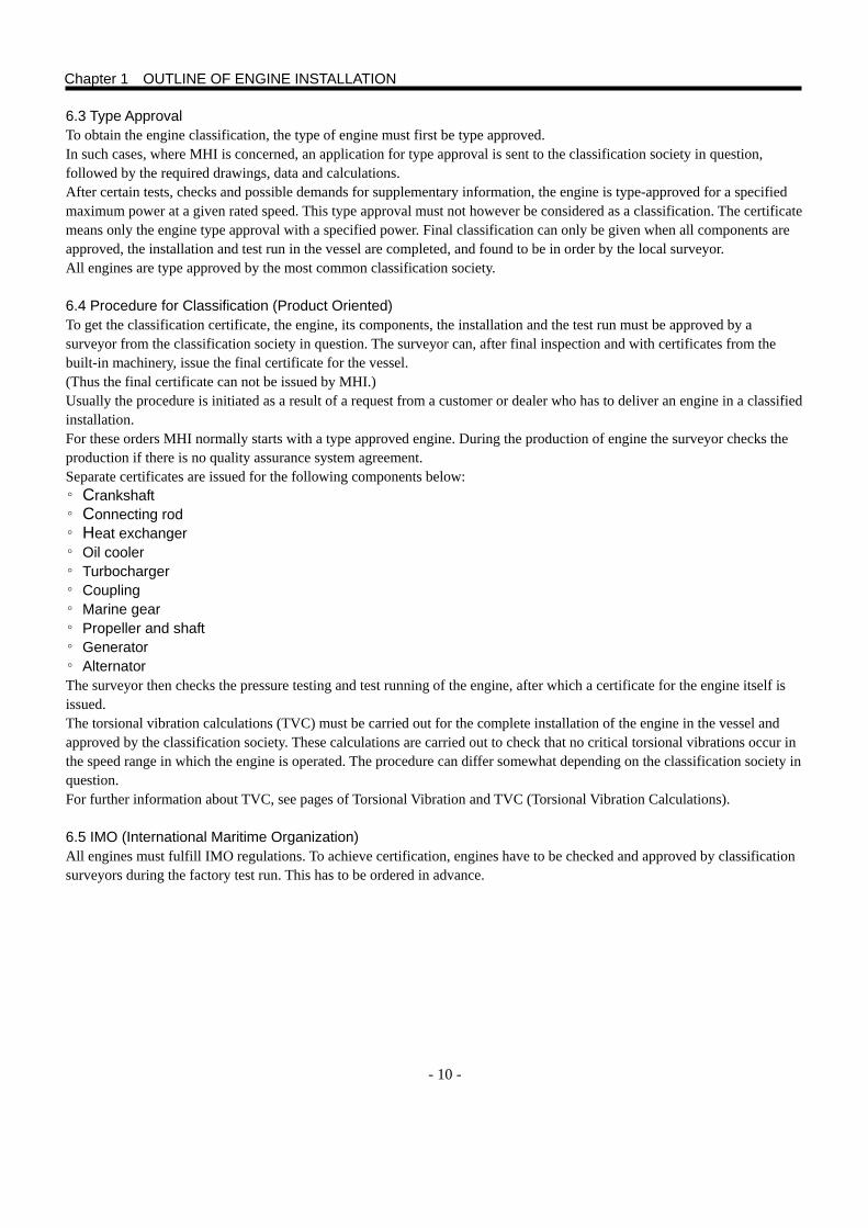
7.1.1 Engine-Marine Gear Direct Coaxial Drive Type···········································································11
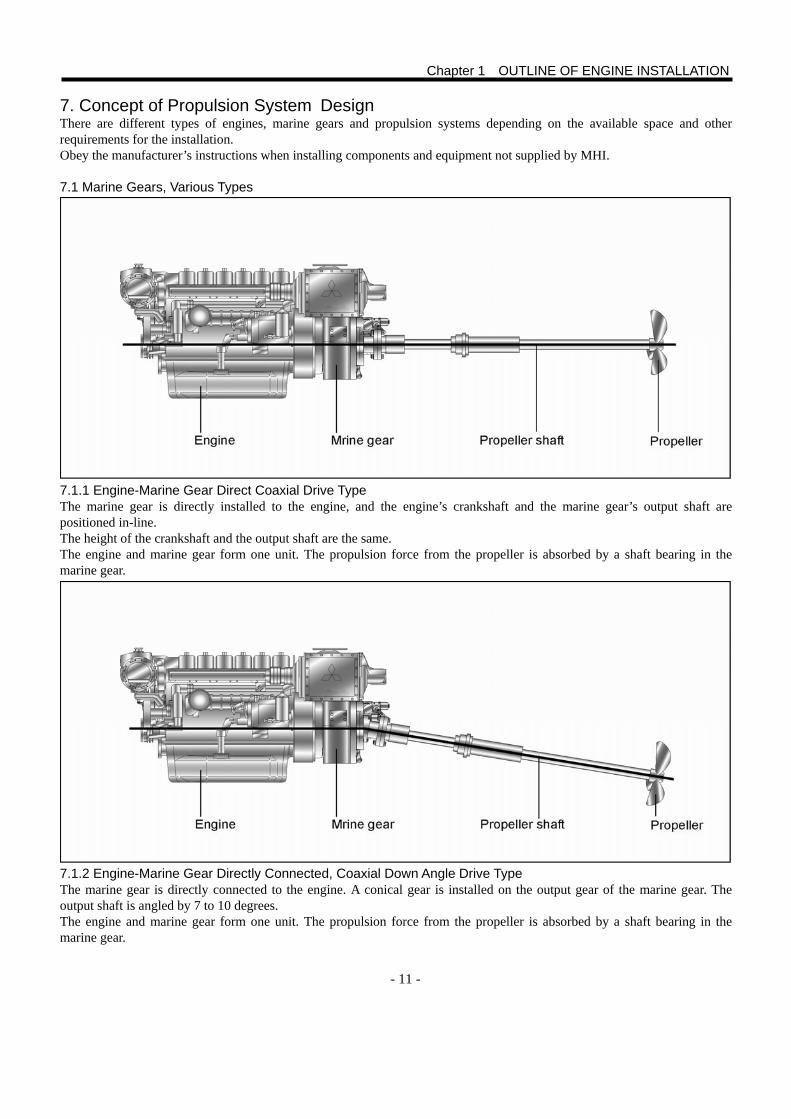
7.1.2 Engine-Marine Gear Directly Connected, Coaxial Down Angle Drive Type ································11
7.1.3 Engine-Marine Gear Directly Connected, Drop Center Parallel Drive Type································12
7.1.4 Engine-Marine Gear Directly Connected, Drop Center Down Angle Drive Type·························12
7.1.5 Separately Positioned Marine Gear, Drop Center Parallel Drive Type ········································13
7.1.6 Separately Positioned Marine Gear, U (V) Shape Drive Type·····················································13
7.2 Other Propulsion Systems··················································································································14
7.2.1 Controllable Pitch Propeller ·········································································································14
7.2.2 Water Jet Drive ····························································································································14
8. Torsional Vibration and TVC (Torsional Vibration Calculations)································15
8.1 Torsional Vibration ······························································································································15
8.2 Torsional Vibration Approvals ·············································································································15
8.3 Torsional Vibration Analysis Data ·······································································································16
9. Arrangement and Planning·········································································································17
9.1 Selection of Engine·····························································································································17
9.2 Selection of Reduction Ratio ··············································································································19
10. Fundamentals of Engine···········································································································20
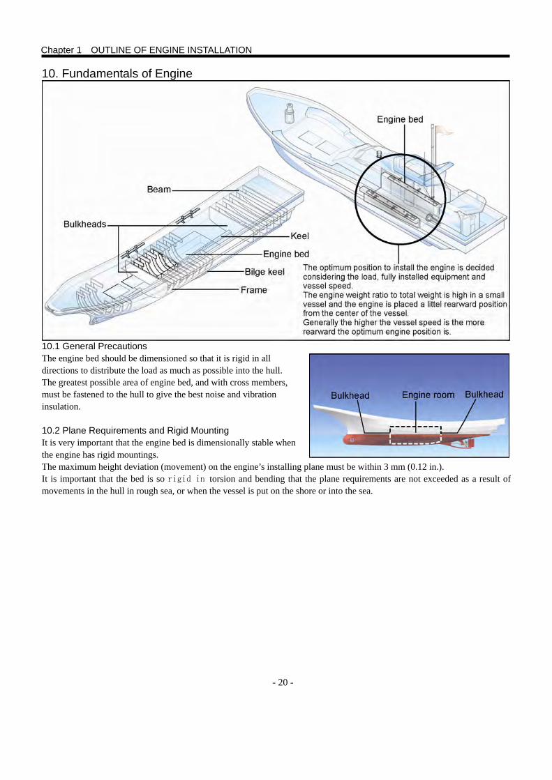
10.1 General Precautions ························································································································20
10.2 Plane Requirements and Rigid Mounting·························································································20
10.3 Engine Bed ·······································································································································21
10.4 Engine Mounting Type······················································································································21
10.5 Rigidity of Engine Bed ······················································································································22
10.6 Installing Angle of Inclination ············································································································22
10.7 Sorts of Engine Bed··························································································································23
10.8 Type of Engine Mounting··················································································································25
10.9 Heat Expansion of Bracket ···············································································································26
11. Propeller Shaft System··············································································································27
11.1 Propeller Shaft and Bearing··············································································································27
11.2 Stern Tube·········································································································································28
11.3 Bearing Wear Standard·····················································································································28
Chapter 2 CENTERING OF SHAFTS
1. Centering Procedure·····················································································································29
1.1 Centering Procedure with Leveling Line·····························································································29
1.2 Centering Procedure with Laser Beam ······························································································31
Chapter 3 INSTALLATION OF ENGINE
1. Size of Engine, Engine Bed and Engine Room································································33
1.1 Size of Engine and Engine Bed··········································································································33
1.2 Size of Engine Room··························································································································33
2. Verification of Engine Room Carry-in Entrance Size and Protection of Engine Room Devices·······································································································································34
2.1 Engine Room Carry-In Entrance Size ································································································34
2.2 Protection of Engine Room·················································································································34
3. Engine Installation··························································································································35
3.1 Check of Lifting Attachment and Devices ···························································································35
4. Provisional Positioning on Engine Bed·················································································36
4.1 Provisional Positioning ·······················································································································36
4.2 Preparation of Adjusting Bolt Block ····································································································36
5. Center on Land and Center of Floatation ············································································37
5.1 Hull Deformation·································································································································37
5.2 Key point of Hull Deformation and Centering in Floating Condition ···················································37
6. Centering Procedure·····················································································································38
7. Check and Adjustment of Centering ······················································································39
7.1 Procedure ···········································································································································39
7.2 Centering Procedure Including an Intermediate Shaft ·······································································41
8. Fixing After Centering ···················································································································42
8.1 Fixing to Engine Bed ··························································································································42
8.2 Flange Fixing ······································································································································43
9. Centering of Front End Equipment················································ 44
9.1 Adjusting and Fixing of Side Power Take Off (PTO) ········································ 44
10. Deflection·········································································································································45
10.1 Deflection of Crankshaft Arm············································································································45
10.2 Deflection Measurement (Procedure When the Measurement Is Required.) ··································45
10.3 Correction Standard··························································································································45
10.4 Cause of Deflection ··························································································································45
11. Protection of Each System after Installation ···································· 46
11.1 Protection of Exhaust System···········································································································46
11.2 Protection of Front Equipment and Rotating Part·············································································46
11.3 Protection of Electrical System ·········································································································46
11.4 Protection of Seawater System ········································································································46
11.5 Separately Installed Equipment ········································································································46
Chapter 4 FUEL SYSTEM
1. Outline···················································································································································47
2. Fuel General···········································································································································47
2.1 Fuel Properties and Composition Affecting the Engine Trouble·························································47
2.2 Flash Point··········································································································································47
2.3 Distillation Characteristics ··················································································································47
2.4 Pour Point (PP)···································································································································47
2.5 Cloud Point (CP)·································································································································47
2.6 Cold Filter Plugging Point (CFPP) ·····································································································47
2.7 Carbon Residue (10% Residual Oil)···································································································48
2.8 Cetane Number ··································································································································48
2.9 Cetane Index ······································································································································48
2.10 Kinetic Viscosity································································································································48
2.11 Sulfur (High Sulfur Content Fuel)······································································································49
2.12 Desulfurized Diesel Fuel, Ultra-Low Sulfur Diesel Fuel ···································································49
2.13 Water Content···································································································································49
2.14 Sediment···········································································································································49
2.15 Ash····················································································································································49
2.16 Copper Plate Corrosion Test ············································································································49
2.17 Coking···············································································································································49
2.18 Aromatics ··········································································································································50
2.19 Asphaltene········································································································································50
2.20 Impurities ··········································································································································50
2.21 Lubrication Performance of Fuel (Indicated by the Wear Trace Diameter in HFRR Wear Tester)···50
2.22 BDF: Bio-Diesel Fuel (Fatty Acid Methyl Ester: FAME)····································································50
2.23 Vanadium, Nickel and Sodium··········································································································50
2.24 Salt Content ······································································································································50
3. MHI Recommended Fuel for Engine ·····················································································51
3.1 Fuel Oil (A: JIS K2205) Sold in Japanese Market ··············································································51
3.2 Low Quality Diesel Fuels in Foreign Countries ··················································································51
3.3 Fuel Quality and Lubrication Oil Quality ·····························································································52
4. Selection of Fuel System Equipment and Piping·····························································54
4.1 Notice to the Fuel Piping Work ···········································································································54
4.2 Fuel Tank ············································································································································55
4.3 Example of Standard Fuel System ·····································································································55
4.4 Additional Installation of Fuel Primary Filter and Fuel-Water Separator·············································56
4.5 Function and Construction of Fuel-Water Separator ··········································································56
5. Lubrication Oil Dilution ·················································································································58
5.1 Dilution Caused by the Fuel Leak from Plunger in Fuel Pump ··························································58
5.2 Dilution Caused by Defective Combustion or Faulty Spray from Injection Nozzle·····························58
Chapter 5 COOLING SYSTEM 1. Outline ·················································································································································59
2. Cooling Passage·····························································································································60
2.1 M(P)TA Type Engine ·······················································································································60
2.2 M(P)TK Type Engine·······················································································································61
3. Seawater Cooling ···························································································································62
4. External Cooling······························································································································63
5. Expansion Tank ·······························································································································65
6. Mitsubishi genuine long life coolant (GLASSY and PG GLASSY) is recommended to use in the MHI diesel engine. ···························································································66
7. Required Performance of Coolant Used for Engine Jacket Water ··························66
8. Required Performance and Quality of Water Used in Coolant ··································66 9. Requirement to Coolant for Stable Antirust and Anti-Corrosion Performance for
Long-Hour Engine Operation································································································67
10. Quality Characteristics of Antifreeze Consisting Mainly of Ethylene Glycol or Propylene Glycol ························································································································67
11. Concentration of Coolant to be Used (in the Case of GLASSY and PG GLASSY Coolants)········································································································································68
12. Precautions to Use MHI Genuine Long Life Coolant: GLASSY and PG GLASSY····································································································69
13. Freezing Temperature of Ethylene Glycol and Propylene Glycol ··························69
Chapter 6 LUBRICATION SYSTEM
1. Outline ·················································································································································73
2. Property···············································································································································73
2.1 Performance Requirement ·················································································································73
2.2 Recommended Viscosity ····················································································································73
2.3 Additive ···············································································································································75
3. Recommended Lubricating Oil ·································································································76
3.1 API CF Class ······································································································································76
3.2 CH-4 Class ·········································································································································76
3.3 Property Standard·······························································································································76
4. Lubrication Oil Deterioration······································································································78
4.1 Factor··················································································································································78
4.1.1 Lubrication Oil ······························································································································78
4.1.2 Contaminant·································································································································78
4.1.3 Oxygen·········································································································································78
4.1.4 Fuel ··············································································································································78
4.2 Effect···················································································································································79
4.2.1 Viscosity ·······································································································································79
4.2.2 Basic Number·······························································································································79
4.2.3 Acid Number·································································································································79
4.2.4 Moisture ·······································································································································79
4.2.5 Flash Point ···································································································································80
4.2.6 Insoluble Matter ···························································································································80
4.3 Service Limit ·······································································································································80
5. Change Interval ·······························································································································80
5.1 Standard Interval·································································································································80
6. Separated Lubrication System ·································································································81
6.1 Priming Pump ·····································································································································81
6.2 Lubrication Oil Heater·························································································································81
Chapter 7 RIGGING
1.Exhaust System································································································································83
1.1 Types of Exhausting Device ···············································································································83
1.2 Dry Type Exhaust Line························································································································84
1.2.1 Condensed Water and Draining Cock ·························································································85
1.2.2 Position of Exhaust Port···············································································································86
1.3 Wet Type Exhaust Line·······················································································································87
1.3.1 Exhaust Line Capacity (Size and Dimensions)············································································87
1.4 Exhaust Flow Resistance Pressure····································································································88
1.5 Acceptable Exhaust Flow Resistance·································································································88
2. Breather Pipe····································································································································89
2.1 Air Bleeding of Crankcase ··················································································································89
2.2 Piping··················································································································································90
3. Starting Device·································································································································91
3.1 Types of Starting Devices ···················································································································91
3.2 Electric starter·····································································································································91
3.3 Air Starter ············································································································································93
3.3.1 Standard Compressed Air Starter ································································································93
3.3.2 Conducting Pipe···························································································································93
3.3.3 Starter Air Tank·····························································································································93
4. Electrical System ····························································································································94
4.1 Electrical Equipment···························································································································94
4.2 Battery ················································································································································94
4.2.1 Capacity ·······································································································································94
4.2.2 Battery Connection ······················································································································95
4.3 Danger of Explosion ···························································································································96
4.4 Charging Condition·····························································································································96
5. Characteristics of Diesel Engine Sound···············································································97
5.1 Engine Sound Source·························································································································97
5.1.1 Combustion Sound ······················································································································97
5.1.2 Mechanical Noise·························································································································97
5.1.3 Inlet Note······································································································································97
5.1.4 Exhaust Note································································································································98
5.1.5 Flow Sound (Excluding Inlet and Exhaust Note) ·········································································98
5.1.6 Others (Structural Sound) ············································································································98
6. Ventilation of Engine Room········································································································99
6.1 Engine Performance···························································································································99
6.2 For the Engine Room Ventilation, Satisfy the Condition Below··························································99
6.3 Engine Output Power and Air Temperature for Combustion ······························································99
6.4 Engine Output Power at an Altitude Higher Than 0 m········································································100
6.5 Function of Inlet and Exhaust Openings ····························································································100
6.6 Size of Air Inlet Opening and Duct······································································································101 6.7 Circuit Pipe or Duct for Inlet and Exhaust ··························································································101 6.8 Engine Room Temperature·················································································································101
7. Front Power Take Off (PTO)······································································································102
7.1 Types of PTO······································································································································102
7.2 Small Power Take Off from Crankshaft Center Pulley········································································103
7.3 PTO from the Front Face of Crankshaft ·····························································································105
7.3.1 Centering to Engine ·····················································································································105
7.3.2 Axial Thrust Force on Crankshaft·································································································105
7.3.3 Allowable Power to Be Taken Off·································································································105
7.4 Torsional Vibration ······························································································································106

8. Rudder House Control (Control Levers) ··············································································107
8.1 Control of Engine and Marine Gear····································································································107
8.2 Installation of Control Cable ···············································································································107
8.3 Twin Lever Type··································································································································108
8.4 Single Lever Type·······························································································································108
8.5 Adjusting and Fixing ···························································································································108
9. Hydraulic Steering System·········································································································109
9.1 Hydraulic Flow ····································································································································109
9.2 Types of Steering Systems ·················································································································109
Chapter 8 SEA TRIAL AND DELIVERRY
1. Inspection of Components and Check of Valves and Switches ································111
1.1 Inspection of Components··················································································································111
1.2 Check of Valve and Switches ·············································································································111
2. Preparation for Operation and Verification with Trial Operation································112
2.1 Starting Procedure······························································································································112
2.2 Engine Warm-Up Operation ···············································································································113
2.3 Check of Marine Gear Operation········································································································114
3. Sea Trial Test····································································································································115
3.1 Cruising Test ·······································································································································115
4. Delivery and Instruction on Delivery ······················································································116
4.1 Delivery···············································································································································116
4.2 Warranty Information and Service Certificate of the Product ·····························································116
4.3 Service Contract ·································································································································116
4.4 Engine Limit Sealing···························································································································116
4.5 Instruction for Handling the Engine ····································································································116
4.6 Spare Parts and Tools·························································································································116

- 1 -
1. Foreword This installation manual contains the information you will need to install your Mitsubishi diesel engines correctly. Check that you have the correct installation manual. This manual uses the term [MHI] for the abbreviation of [Mitsubishi Heavy Industries, Ltd.]
Read the Safety Precautions and General Information in this installation manual carefully before servicing or operating the engine. IMPORTANT The following special warning symbols are found in this manual. Also you will find these symbols on the engine. WARNING indicates a potentially hazardous situation which, if not avoided, could result in death or serious injury. Be
sure to obey the instructions. CAUTION indicates a potentially hazardous situation which, if not avoided, may result in minor or moderate injury. NOTE: indicates important information to facilitate work processes or operation. Below is a list of the risks that you must always be aware of and the safety measures you must always carry out.
Plan in advance so that you have enough room for safe installation and (future) dismounting. Plan the engine compartment including other rooms for inspection and servicing to be safe and easy for the work. Make sure it is not possible to come into contact with rotating components, hot surfaces or sharp edges when inspecting and servicing the engine.
Ensure that all equipment such as pump drives and compressors has protective covers. Stop the engine and turn off the power at the main switch (breaker) before starting work on the electrical system. Keep the switches in the OFF position during the work, and set up a warning notice not to operate the machine at the controlling, operating and steering points.
Do not work on a running engine. However, some works such as adjustments are allowed on a running engine if it is absolutely necessary. Approaching an engine that is running is dangerous. Loose clothing or long hair can be tangled with rotating parts, and may result in a serious injury.
Take precautions to avoid hot surfaces (exhaust pipes, turbochargers, inlet air manifolds and others), hot lubrication oil and water during engine running and immediately after the stopping.
Reinstall all protective parts removed during service operations before starting work on the engine.
Ensure that the warning or information decals on the product are always visible. Replace a decal if it is damaged or illegible.
Be sure to install the air cleaner or pre-cleaner to the engine. Never start the engine without installing the air cleaner or pre-cleaner. The rotating compressor parts in the turbocharger can cause serious personal injury. Also the operation without air cleaner or-pre-cleaner will cause damage to the compressor, piston rings and cylinder liners.

- 2 -
Never use a flammable starting aid such as ether spray into the air intake. Use of such products could result in an explosion in the air inlet pipe and may cause personal injury.
Never open the filler cap for the engine coolant when the engine is hot. Steam or hot engine coolant can be ejected by the pressure in the cooling system. Open the filler cap slowly and release coolant system pressure progressively, if the filler cap or drain cock must be opened, or if a plug or engine coolant pipe must be removed on a hot engine.
Hot oil can cause burns. Avoid skin contact with hot oil. Ensure that the oil system is depressurized before starting working on it. Never start or run the engine without the oil filler cap in place because of the risk of oil being ejected.
If the boat is in the water, stop the engine and close the bottom valve before starting operations on the cooling system.
Start the engine only in an area that is well ventilated. Exhaust gas is toxic. Do not breathe in. When operating in an enclosed area, use exhaust extraction to lead the exhaust and crankcase gases away from the place of work.
Always wear protective goggles if there is a risk of splinters, grinding sparks and splashes from acid or other chemicals. Or you may loose your eye sight.
Avoid skin contact with oil. Long term or repeated skin contact with oil can lead to the loss of natural oils from the skin. This leads to irritation, dry skin, eczema and other skin problems. Old oil is more dangerous to your health than new oil. Wear protective gloves and avoid oil-soaked clothes and rags. Wash hands regularly, especially before meals. Use protective skin creams to help clean and to stop dry skin.
Most chemicals intended for the product (engine and marine gear oils, glycol in coolant, gasoline and diesel fuel), or such chemicals used in the workshop as solvents are harmful to your health. Read the instructions on the packaging carefully. Always obey the protective measures (using a protective mask, goggles, gloves etc.). Make sure that other personnel are not unknowingly exposed to harmful substances, in the air that they breathe for example. Ensure that ventilation is good. Dispose of used and excess chemicals as instructed.
Be careful when tracing leaks in the fuel system and when testing injectors. Wear protective goggles. The jet from an injector is under very high pressure and fuel can penetrate deep into tissue, causing serious injury with a risk of blood poisoning.
All fuels and many chemicals are flammable. Keep away from naked flames or sparks. Gasoline, some solvents and hydrogen from batteries in the correct proportions with air are very flammable and explosive. Do not smoke! Maintain good ventilation and take necessary safety measures before welding or grinding in the vicinity. Always keep a fire extinguisher accessible in the workplace.
Store oil- and fuel-soaked rags, old fuel and oil filters properly. Oil-soaked rags can, in certain circumstances, ignite spontaneously. Old fuel and old filters are environmentally harmful. Carry them with used lubrication oil, contaminated fuel and solvents to a proper refuse station and dispose of them as environmentally harmful material.
Chapter 1 OUTLINE OF ENGINE INSTALLATION
- 3 -
Ensure that the battery compartment is designed according to current safety standards. Never allow an open flame or electric sparks near the batter area. Never smoke near the batteries. The battery discharge hydrogen gas during charging and the gas and air mixture is explosive. This gas is easily ignited and highly explosive. Incorrect connection of the battery can cause sparks sufficient to cause an explosion and damage the battery. Do not lean over the battery when charging the battery or operating the engine.
Always ensure that the plus (positive) and minus (negative) battery leads are correctly installed on the corresponding terminal posts on the battery. Incorrect installation can result in serious damage to the electrical equipment. Pay special attentions to install the electric leads to electronic controllers for the correct wiring. Refer to the wiring diagrams.
Always wear protective goggles when charging and handling batteries. The battery electrolyte contains extremely corrosive sulfuric acid. If this electrolyte comes in contact with the skin, immediately wash with soap and plenty of water. If the electrolyte comes in contact with an eye, flush immediately with plenty of water and seek medical advice.
Stop the engine before adjusting the marine gear.
Use the lifting eyes fitted on the engine or marine gear when lifting. Check the capacity of the lifting equipment and ensure the capacity enough to lift the engine and marine gear. (The weight of marine gear and other equipment are sometimes included in the engine weight.)
To ensure safe lifting and avoid damage to components installed on the engine, us an adjustable lifting beam. Hitch all chains and cables in parallel to each other and square to the engine as far as possible.
If extra equipment is installed and the center of gravity is shifted, prepare a proper lifting device and keep the correct balance for lifting.
Do not perform the work on an engine suspended with a hoist.
Never work alone when installing heavy components, even when using secure lifting equipment such as lockable block and lifting jig. Most lifting devices require two people. One handles the lifting device and the other keeps watch on components not to get caught and damaged.
The components in the electrical system and fuel system used in marine engines are designed and manufactured to minimize risks of fire and explosion. Do not operate the engine in an environment with a possibility of explosion.
Always use fuels recommended by MHI. Refer to the Operation and Maintenance Manual. Use of a low quality fuel can be the cause of engine failure. On a diesel engine low quality fuel can cause the fuel control rack to stick causing the engine to over-speed with resulting risk of damaging the engine and personal injury. Low quality fuel can also lead to higher maintenance costs.
Never operate the engine by controlling the fuel rack manually. This will lead to over-speeding of the engine and engine and/or generator will be damaged. Parts thrown from the over-speeding engine and generator can lead to personal injury.
Chapter 1 OUTLINE OF ENGINE INSTALLATION
- 4 -
2. General Information 2.1 About this Installation Manual This manual is intended as a guide for the installation of marine engines for inboard use. This manual is not comprehensive and does not cover every possible installation. This manual is to be regarded as recommendations and guide lines by MHI. These recommendations are the results of time-proven experiences of practical engine installations all over the world. However, departures from recommended procedures are sometimes inevitable or preferable. In those cases, MHI will be glad to offer assistance in finding a solution of installation procedure for the customer’s requirement. It is solely the installer’s responsibility to ensure the smooth and complete installation work. The work must be in a good order, use approved material and accessories, and comply with the rules and regulations. This installation manual has been published for professionals and qualified personnel. Therefore the persons using this manual are assumed to have the basic knowledge of marine drive systems and be able to perform the related mechanical and electrical work. MHI continuously improves its products and reserves the right to make changes. All the information contained in this manual is based on the product data available at the time of editorial work. Notification of any important modifications to the product will be made in Service Bulletins. 2.2 Careful Installation Plan Great care must be taken in the installation of engine and components. The care will bring the satisfactory result. Always make sure that the correct specifications, drawings and any other data are available before starting the work. Be sure to check before starting the work. This will allow the correct planning and installation from the start. Plan the engine room so that the routine service operation is easy to perform including the parts replacement job. Utilize the engine’s Service Manual and the drawings showing dimensions. It is very important when installing the engine that no dust or other foreign substances get into the fuel, cooling intake and turbocharger systems. Or the engine will be suffered from seizure or failure. For this reason, the systems must be covered. Clean supply lines and hoses before connecting them to the engine. Remove the protective engine plug only when making a connection to an external system. 2.3 Emission Regulations Certified Engines The manufacturer of engines certified for national and local environment registration pledges that this registration is met by both new and currently operational engines. The product must compare with the example approved for certification purpose. So that MHI, as a manufacturer, can pledge that currently operational engines meet environmental regulations, the following must be obeyed for the installation. ○ Adjustment of injection timing, and inspection and repair of fuel injection pump, fuel injection nozzle and turbocharger
must always be performed by an approved MHI workshop. ○ Installation of exhaust pipes and intake ducts for the engine compartment must be carefully planned. If the ventilation
capacity is insufficient, exhaust gas components may be affected. ○ Never break the seals which set the fuel injection amount. CAUTION Use only MHI genuine parts. Using of non-genuine parts will mean that MHI will no longer take responsibility for the engine meeting the certified design. All damages and costs caused by the use of non-genuine replacement parts will not be covered by MHI.
Chapter 1 OUTLINE OF ENGINE INSTALLATION
- 5 -
2.4 Classification Society Vessels for commercial activities must be approved by the classification society or by the navigation authority for the vessel’s registered country. 2.5 Liability of Engine Maintenance The engine consists of many components working together. One component deviated from its technical specification can cause a drastic increase in the environmental impact and damage to the engine. It is therefore the absolute requirement to adjust the systems properly and to use MHI genuine parts. Certain systems such as components in the fuel system may require special expertise and special testing equipment. Some components are sealed at the factory for the prevention of failure and accident or environmental reasons. Never work on sealed components except for the case worked on by authorized personnel. Most chemical products damage the environment if used incorrectly. MHI recommends the use of biodegrading degreasing agents for cleaning engine components, unless otherwise indicated in the manual. Take special care when working on board to ensure that oil and waste are stored as environment destructive material and not accidentally pumped into the environment with bilge water. 2.6 Engine Performance Test MHI is glad to perform the open engine performance test at the customer’s request. This is held in the factory and customers can participate in the test run.
Before sea trial, all systems are tested by the shipyard and MHI or its dealer as a collaborative work. When these test are performed and approved by the parties, the vessel is ready for the sea trial.
In the sea trial, the engine performance, propeller matching, vessel maneuverability and others are tested. The vessel systems must be approved by the all parties in all items.
Vessels are classified by use, and all systems and function must be tested and approved by a local surveyor. If extra equipment is installed, it must satisfy the classification rules. Some equipment have type approval document which means the equipment can have the classification certificate.
All the classification rules are made to provide a safe sailing for on board personnel and to prevent accidents which can lead to negative environmental effects.
Normally vessels with classification signs are safer and have classification surveyors check the vessel regularly.
Chapter 1 OUTLINE OF ENGINE INSTALLATION
- 6 -
3. Environment of Marine Engine 3.1 Marine Engine and Its Environment Marine engines, like engines for cars and trucks, are rated according to the specification. The output is indicated in kW, usually at the maximum engine speed. Most engines will produce their rated power under the conditions specified in the power output standard after a proper running-in period. The output tolerances for line produced engines are usually 5% according to ISO standards.
3.2 Measuring Output The engine power output is usually taken out from the flywheel. And losses occur in transmission and propeller shaft bearings before the power reaches the propeller. The amount of these losses is approximately 4 to 6 %. All major marine engine manufacturers indicate the engine power according to ISO 3046. It means the gross crankshaft output power (excluding marine gear). 3.3 Engine Performance Engine output is affected by a number of different factors. The main factors are atmospheric pressure, ambient temperature, humidity, fuel thermal value, fuel temperature and back pressure. Deviations from normal values affect the engine differently. Diesel engines use a large amount of air for combustion. If the mass flow of the air is reduced, the first sign is black smoke. The effect of this sign is especially noticeable at acceleration or under a high load where the engine produces a high torque. When the mass flow decreases substantially a diesel engine will lose the power. The engine cannot generate the required torque when the decrease of air flow is significant. It is important to keep the exhaust back-pressure at a low level. The power losses caused by back-pressure are directly proportional to the increase of back-pressure, which also increases the exhaust temperature. Thermal value of fuel differs according to the market, and affects the engine output. Environmental-friendly fuel, which is compulsory in some markets, has a low thermal value. Engine output may be reduced by approximately 8 % compared with the fuel specified in the ISO standard. 3.4 Propeller Selection A naval architect, marine engineer or other qualified person should select the propeller. The required engine performance data to select the propeller is available in the technical literature. The important factor to select a propeller is the correct data of engine speed. However, it is advisable to reduce the pitch to some degree to cope with varying weather conditions and marine growth. There are two types of propeller systems: CPP; controllable pitch propeller and FPP; fixed pitch propeller.
3.4.1 CPP (Controllable Pitch Propeller) From the view point of engine, this type of propeller has an advantage to prevent the engine from overloading. Some PPT systems allow the independent propeller pitch and engine speed. In those cases a slow engine speed with a too large pitch is concerned. This is because of the CPP system tendency to become an over pitch. The situation leads to a premature wear of engine parts. In a correctly designed CCP electronic device, the propeller load is controlled to prevent the engine speed from being decreased. In general the CCP system gives a quick maneuverability and is normally used in ferries and cargo vessels with many maneuvers in a day or in vessels operating under a wide variety of load conditions.
Chapter 1 OUTLINE OF ENGINE INSTALLATION

- 7 -
3.4.2 FPP (Fixed Pitch Propeller) The characteristic of the FPP system is reduced loads during acceleration. When the vessel reaches its nominal speed, the load returns to the designed and specified value. When using the FPP, it is important to make a proper design of the propeller to avoid a constant overload of the engine. In the first sea trial, the engine speed should be higher than the nominal speed by 3 to 5% at the maximum loading. The engine speed will fall down when the vessel hull is fouled and the bottom paint is worn out. When the vessel is sailing against a strong wind, the speed is reduced and the engine load is increased. A properly designed propeller and smooth acceleration will protect the engine from overload. If the engine speed is below the nominal value during the first sea trial, this will lead to the premature wear of engine parts in the future. And results will be the frequent necessity of inspections and overhauling. FFP is the most common propeller system due to the simple construction and a small number of moving parts. The FFP system is used in all types of vessels.
Chapter 1 OUTLINE OF ENGINE INSTALLATION
- 8 -
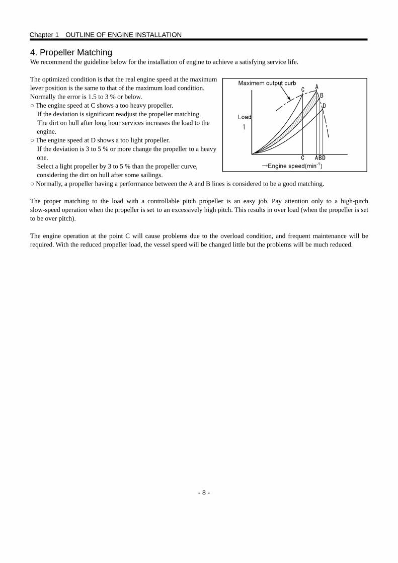
4. Propeller Matching We recommend the guideline below for the installation of engine to achieve a satisfying service life. The optimized condition is that the real engine speed at the maximum lever position is the same to that of the maximum load condition. Normally the error is 1.5 to 3 % or below. ○ The engine speed at C shows a too heavy propeller.
If the deviation is significant readjust the propeller matching. The dirt on hull after long hour services increases the load to the engine.
○ The engine speed at D shows a too light propeller. If the deviation is 3 to 5 % or more change the propeller to a heavy one. Select a light propeller by 3 to 5 % than the propeller curve, considering the dirt on hull after some sailings.
○ Normally, a propeller having a performance between the A and B lines is considered to be a good matching. The proper matching to the load with a controllable pitch propeller is an easy job. Pay attention only to a high-pitch slow-speed operation when the propeller is set to an excessively high pitch. This results in over load (when the propeller is set to be over pitch). The engine operation at the point C will cause problems due to the overload condition, and frequent maintenance will be required. With the reduced propeller load, the vessel speed will be changed little but the problems will be much reduced.
Chapter 1 OUTLINE OF ENGINE INSTALLATION
- 9 -
5. Operating Environment 5.1 World Operating Temperature Seawater temperature Design seawater temperature is according to classification societies and is normally 32℃ (90℉). Environmental temperature The lowest ambient temperatures in the world for the consideration of engine installation are shown below. The world is divided into the following temperature zones: A North Europe: 35 ℃ B South Europe: 40 ℃ C Scandinavian countries and UK: 30 ℃ D North America, Canada, Central and South America, Parts of Asia: 40 ℃ E Africa, Middle and Far East, Australia and the South Pacific countries: 50 ℃ The temperatures specified for various parts of the world are base on the average of the highest monthly shaded ambient temperatures recorded over a number of years. It is the responsibility of the ship yard / customer to ensure that the cooling system specification is suitable for the area where the application is operated. However, no matter how the cooling tests are carried out under the various conditions, it does not guarantee that occasional overheating of machines in service will not occur. Considering hotter weather than that of the average or recent abnormal weather, it is advisable that the cooling systems are designed with some margins. 6. General Information about Classification The classification procedures are outlined below. The procedures are changed from time to time by the classification societies. The classification procedure was originated for the purpose of introducing similar and comparable rules and regulations for among other things, the production and maintenance of ships, their machinery and equipment. As a result of these rules and regulations, “safety at sea” was improved and better documentations were introduced for insurance matters. The government authorities in most countries concerned with maritime matters have authorized the classification societies to handle these rules and audit the ships. NOTE: This installation manual does not give full information concerning to the classification. Please contact an authorized classification society for the complete information. 6.1 Classified Engine and Range of Use An engine with equipment that is used in a classified vessel must be approved by the classification society which handles matters relating to ships seaworthiness. The rules apply to the propulsion engine, auxiliary engine, power take of, reverse gear, shaft, propeller and others. This means that if the installation needs to be classified, it must be stated clearly when addressing the inquiry and quotation request to MHI. 6.2 Special Rules for Different Operational Conditions The classification societies have, in general, different rules relating to the following: Varying shipping conditions
e.g.: 1 Shipping in tropical water, 2 Coastal shipping, 3 Ocean shipping, 4 Operation in ice (several different classes) Type of load
e.g.: 1 Passenger shipping, 2 Tanker shipping, 3 Freezer shipping Type of manning e.g.: 1 Unmanned machine room, 2 Manned machine room These rules are adapted so that each vessel can be assured to function faultlessly in the area or type of operation for which it is approved.
Chapter 1 OUTLINE OF ENGINE INSTALLATION
- 10 -
6.3 Type Approval To obtain the engine classification, the type of engine must first be type approved. In such cases, where MHI is concerned, an application for type approval is sent to the classification society in question, followed by the required drawings, data and calculations. After certain tests, checks and possible demands for supplementary information, the engine is type-approved for a specified maximum power at a given rated speed. This type approval must not however be considered as a classification. The certificate means only the engine type approval with a specified power. Final classification can only be given when all components are approved, the installation and test run in the vessel are completed, and found to be in order by the local surveyor. All engines are type approved by the most common classification society. 6.4 Procedure for Classification (Product Oriented) To get the classification certificate, the engine, its components, the installation and the test run must be approved by a surveyor from the classification society in question. The surveyor can, after final inspection and with certificates from the built-in machinery, issue the final certificate for the vessel. (Thus the final certificate can not be issued by MHI.) Usually the procedure is initiated as a result of a request from a customer or dealer who has to deliver an engine in a classified installation. For these orders MHI normally starts with a type approved engine. During the production of engine the surveyor checks the production if there is no quality assurance system agreement. Separate certificates are issued for the following components below: ◦ Crankshaft ◦ Connecting rod ◦ Heat exchanger ◦ Oil cooler ◦ Turbocharger ◦ Coupling ◦ Marine gear ◦ Propeller and shaft ◦ Generator ◦ Alternator The surveyor then checks the pressure testing and test running of the engine, after which a certificate for the engine itself is issued. The torsional vibration calculations (TVC) must be carried out for the complete installation of the engine in the vessel and approved by the classification society. These calculations are carried out to check that no critical torsional vibrations occur in the speed range in which the engine is operated. The procedure can differ somewhat depending on the classification society in question. For further information about TVC, see pages of Torsional Vibration and TVC (Torsional Vibration Calculations).
6.5 IMO (International Maritime Organization) All engines must fulfill IMO regulations. To achieve certification, engines have to be checked and approved by classification surveyors during the factory test run. This has to be ordered in advance.
Chapter 1 OUTLINE OF ENGINE INSTALLATION
- 11 -
7. Concept of Propulsion System Design There are different types of engines, marine gears and propulsion systems depending on the available space and other requirements for the installation. Obey the manufacturer’s instructions when installing components and equipment not supplied by MHI. 7.1 Marine Gears, Various Types 7.1.1 Engine-Marine Gear Direct Coaxial Drive Type The marine gear is directly installed to the engine, and the engine’s crankshaft and the marine gear’s output shaft are positioned in-line. The height of the crankshaft and the output shaft are the same. The engine and marine gear form one unit. The propulsion force from the propeller is absorbed by a shaft bearing in the marine gear. 7.1.2 Engine-Marine Gear Directly Connected, Coaxial Down Angle Drive Type The marine gear is directly connected to the engine. A conical gear is installed on the output gear of the marine gear. The output shaft is angled by 7 to 10 degrees. The engine and marine gear form one unit. The propulsion force from the propeller is absorbed by a shaft bearing in the marine gear.
Chapter 1 OUTLINE OF ENGINE INSTALLATION
- 12 -
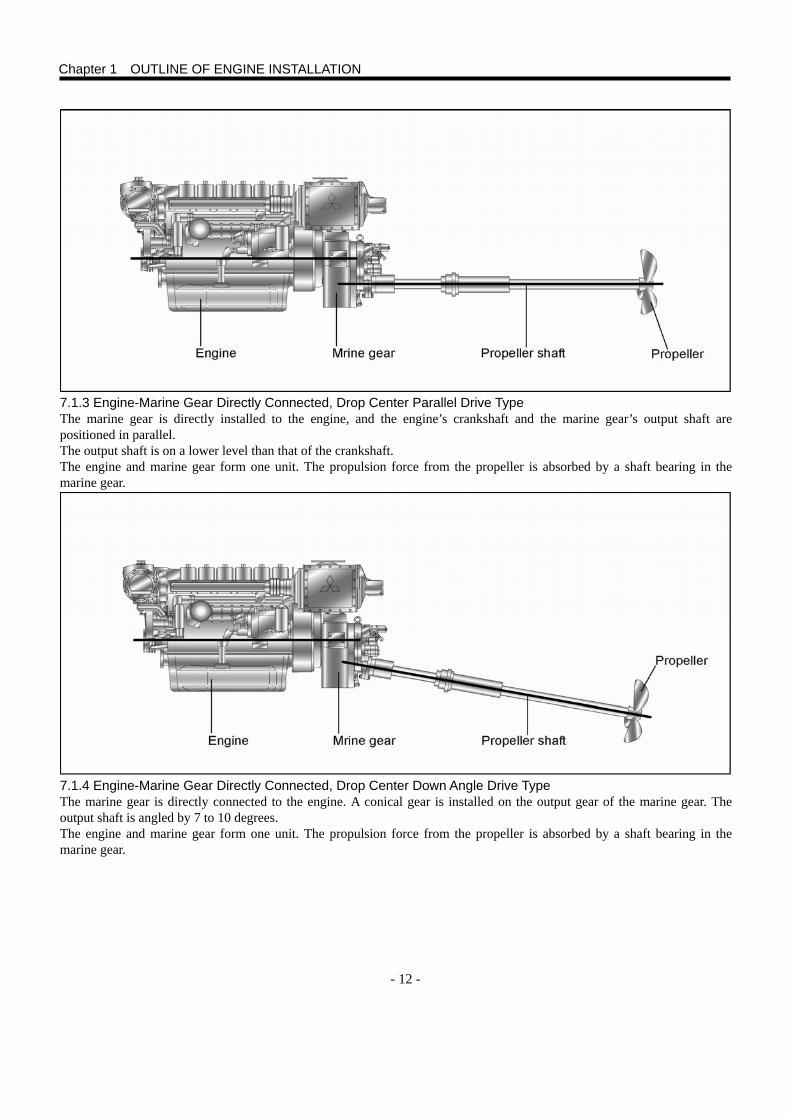
7.1.3 Engine-Marine Gear Directly Connected, Drop Center Parallel Drive Type The marine gear is directly installed to the engine, and the engine’s crankshaft and the marine gear’s output shaft are positioned in parallel. The output shaft is on a lower level than that of the crankshaft. The engine and marine gear form one unit. The propulsion force from the propeller is absorbed by a shaft bearing in the marine gear. 7.1.4 Engine-Marine Gear Directly Connected, Drop Center Down Angle Drive Type The marine gear is directly connected to the engine. A conical gear is installed on the output gear of the marine gear. The output shaft is angled by 7 to 10 degrees. The engine and marine gear form one unit. The propulsion force from the propeller is absorbed by a shaft bearing in the marine gear.
Chapter 1 OUTLINE OF ENGINE INSTALLATION
- 13 -
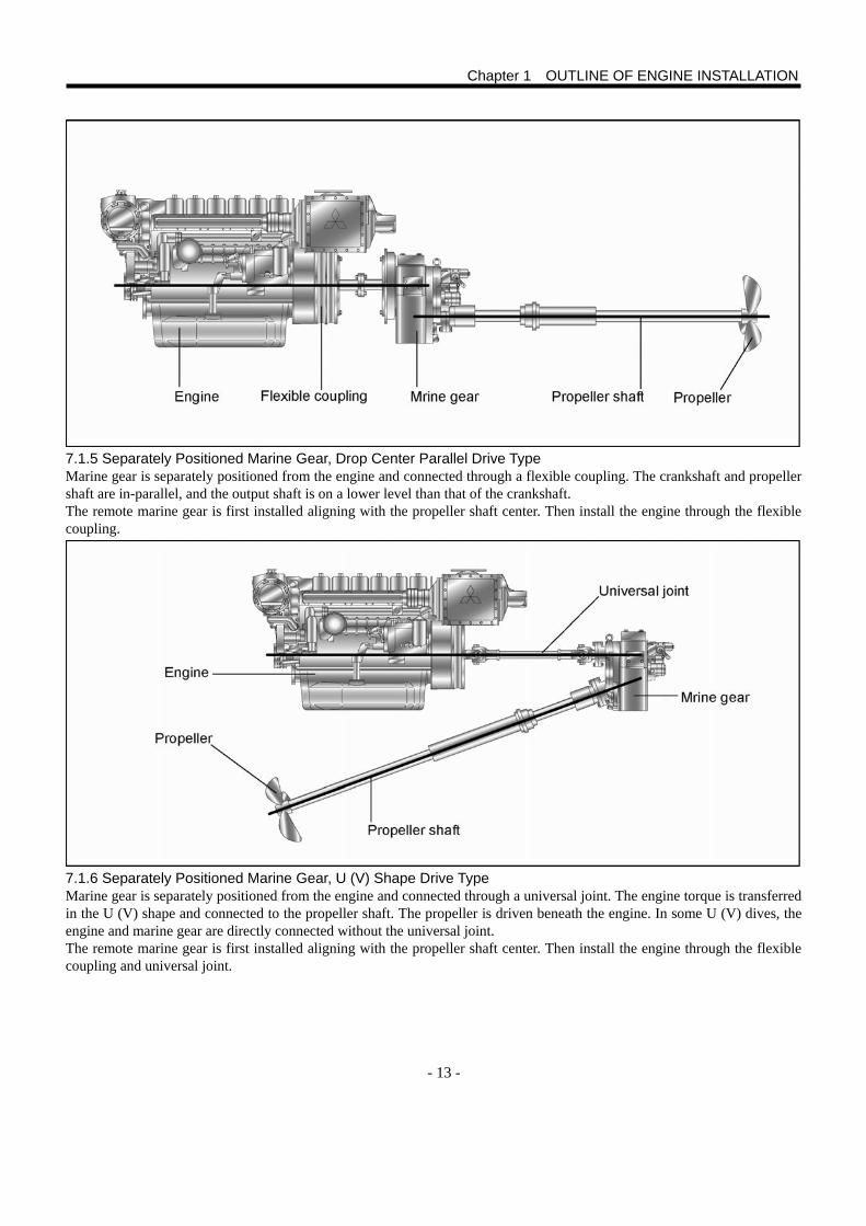
7.1.5 Separately Positioned Marine Gear, Drop Center Parallel Drive Type Marine gear is separately positioned from the engine and connected through a flexible coupling. The crankshaft and propeller shaft are in-parallel, and the output shaft is on a lower level than that of the crankshaft. The remote marine gear is first installed aligning with the propeller shaft center. Then install the engine through the flexible coupling. 7.1.6 Separately Positioned Marine Gear, U (V) Shape Drive Type Marine gear is separately positioned from the engine and connected through a universal joint. The engine torque is transferred in the U (V) shape and connected to the propeller shaft. The propeller is driven beneath the engine. In some U (V) dives, the engine and marine gear are directly connected without the universal joint. The remote marine gear is first installed aligning with the propeller shaft center. Then install the engine through the flexible coupling and universal joint.
Chapter 1 OUTLINE OF ENGINE INSTALLATION
- 14 -
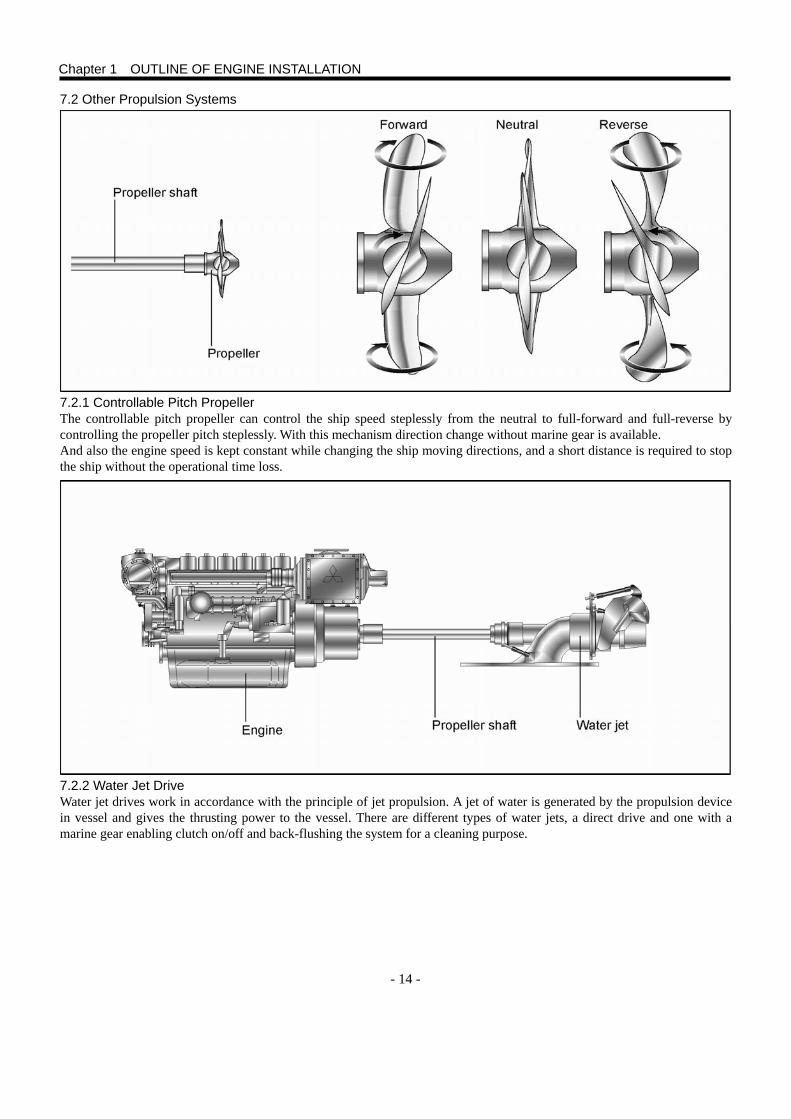
7.2 Other Propulsion Systems 7.2.1 Controllable Pitch Propeller The controllable pitch propeller can control the ship speed steplessly from the neutral to full-forward and full-reverse by controlling the propeller pitch steplessly. With this mechanism direction change without marine gear is available. And also the engine speed is kept constant while changing the ship moving directions, and a short distance is required to stop the ship without the operational time loss. 7.2.2 Water Jet Drive Water jet drives work in accordance with the principle of jet propulsion. A jet of water is generated by the propulsion device in vessel and gives the thrusting power to the vessel. There are different types of water jets, a direct drive and one with a marine gear enabling clutch on/off and back-flushing the system for a cleaning purpose.
Chapter 1 OUTLINE OF ENGINE INSTALLATION
- 15 -
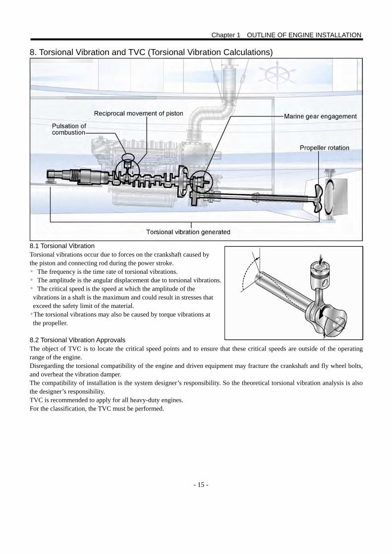
8. Torsional Vibration and TVC (Torsional Vibration Calculations) 8.1 Torsional Vibration Torsional vibrations occur due to forces on the crankshaft caused by the piston and connecting rod during the power stroke. ◦ The frequency is the time rate of torsional vibrations. ◦ The amplitude is the angular displacement due to torsional vibrations. ◦ The critical speed is the speed at which the amplitude of the vibrations in a shaft is the maximum and could result in stresses that exceed the safety limit of the material. ◦The torsional vibrations may also be caused by torque vibrations at the propeller.
8.2 Torsional Vibration Approvals The object of TVC is to locate the critical speed points and to ensure that these critical speeds are outside of the operating range of the engine. Disregarding the torsional compatibility of the engine and driven equipment may fracture the crankshaft and fly wheel bolts, and overheat the vibration damper. The compatibility of installation is the system designer’s responsibility. So the theoretical torsional vibration analysis is also the designer’s responsibility. TVC is recommended to apply for all heavy-duty engines. For the classification, the TVC must be performed.
Chapter 1 OUTLINE OF ENGINE INSTALLATION
- 16 -
8.3 Torsional Vibration Analysis Data MHI will do the torsional analysis on receipt of the necessary details from the customer. The following technical data are required to perform the analysis. ○ Operating speed range; lowest to highest speeds ○ Maximum power output ○ Detailed drawing of rotating components ○ Inertia moments of rotating components and their locations ○ The general layout drawing is needed for a complicated installation For the purpose of TVC, most of the drive line manufacturers provide shaft drawings with moments of inertia and their positions on the shaft. The drive package consisting of engine, flexible coupling and marine gear supplied by MHI is constructed as one unit and has the lowest possible torsional vibration level in terms of a standard propeller system. MHI conducts the TVC if other combinations are to be used. Incorrectly selected components in the drive package can result in abnormally high stress in the engine crankshaft.
Chapter 1 OUTLINE OF ENGINE INSTALLATION
- 17 -
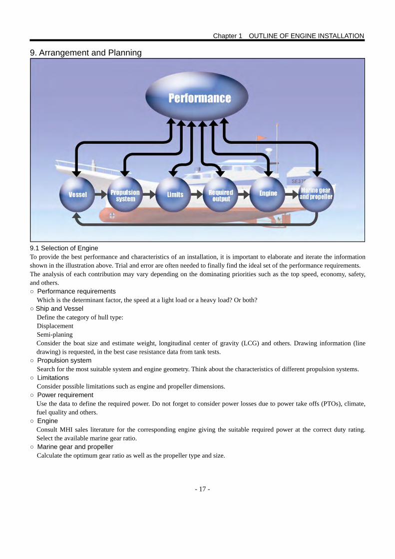
9. Arrangement and Planning 9.1 Selection of Engine To provide the best performance and characteristics of an installation, it is important to elaborate and iterate the information shown in the illustration above. Trial and error are often needed to finally find the ideal set of the performance requirements. The analysis of each contribution may vary depending on the dominating priorities such as the top speed, economy, safety, and others. ○ Performance requirements
Which is the determinant factor, the speed at a light load or a heavy load? Or both? ○ Ship and Vessel
Define the category of hull type: Displacement Semi-planing Consider the boat size and estimate weight, longitudinal center of gravity (LCG) and others. Drawing information (line drawing) is requested, in the best case resistance data from tank tests.
○ Propulsion system Search for the most suitable system and engine geometry. Think about the characteristics of different propulsion systems.
○ Limitations Consider possible limitations such as engine and propeller dimensions.
○ Power requirement Use the data to define the required power. Do not forget to consider power losses due to power take offs (PTOs), climate, fuel quality and others.
○ Engine Consult MHI sales literature for the corresponding engine giving the suitable required power at the correct duty rating. Select the available marine gear ratio.
○ Marine gear and propeller Calculate the optimum gear ratio as well as the propeller type and size.
Chapter 1 OUTLINE OF ENGINE INSTALLATION
- 18 -
Plan the engine room so as not to restrain the engine servicing work. Refer to the maintenance manuals and make sure that all filter replacement, oil change and other servicing measures can be carried out normally. Also ensure the installation and removing of the engine. Before starting any installation work, make sure that up-to-date dimensional drawings for the engine and its equipment are used. Dimensional drawings provide all the necessary measures for installation, such as the distance from the center of the crankshaft to the engine brackets (marine gear brackets) and to the center line of the propeller shaft. NOTE: Do not use the small silhouette drawings on leaflets and brochures for the installation job. The engine and drive line should be installed in such a way as to minimize the noise and vibrations, in other words air noise and body noise (vibrations). Vibrations from the engine and propeller are transmitted through the suspension and engine bed to the hull. Other channels are through the exhaust pipe, coolant pipes, fuel pipes, cables and control cables. Pressure shocks from the propeller are transmitted through the water into the hull. Pulsation force on the propeller goes into the hull through the support brackets, bearings and seals. If the propeller is at a large angle this pulsating pressure and force can be considerable. Use of an incorrect propeller can result in cavitation, which also causes noise and vibration. Tosional vibrations from correctly selected components in the drive package are often negligible. NOTE: Always consider international and local requirements and regulations. ○ Engine room layout
Use only updated and approved dimensional drawings. Study the drawings carefully. Consider the engine’s movements when running and the accessibility for servicing and repair. For the twin-engine twin-shaft installation, the distance between the engines should be sufficient to allow an easy access for inspection and service work.
○ Selection of engine mounting type Select the appropriate type of engine suspension based on the comfort requirements, type of use and engine/marine gear arrangement. The engines are mainly mounted by fixed mounting or elastic mounting type. In the fixed system, the engine and marine gear are directly bolted to the engine bed. While in the elastic system, the engine and marine gear are installed on flexible mounts. Select a shaft system depending on the type of coupling (fixed or elastic), shaft support, stuffing box and others.
○ Fuel system Determine the type of fuel system. Select the use of fuel hoses or fuel pipes. And consider the classification rules. Decide where to place the extra water separated from fuel filters and plan for the routing of fuel hoses and pipes, fuel filter and venting hoses, shut-off devices and others. Fuel feed and return hoses or pipes must be dimensioned correctly.
○ Cooling system Determine the type of cooling system. Select where to place seawater intake, seawater filter, keel cooler and others. Plan the routing and dimensions of water pipes.
○ Exhaust system Determine the type of exhaust system. Plan the installation of the exhaust line components, such as silencer and exhaust pipe.
○ Starting system Select starting system suitable for the intended type of use. MHI offers electric and air starting systems.
○ Electrical system Plan the routing cables and .check the length of instrument cable harnesses. Decide where to place the fuse box and main switch.
CAUTION Avoid joints and cable connections where there is a risk of moisture or water. Do not make any joints or connections behind fixed bulkheads or similar where the access becomes difficult after finishing the vessel.
Chapter 1 OUTLINE OF ENGINE INSTALLATION
- 19 -
○ Electrochemical corrosion
The potential problem of galvanic and stray current corrosion must be considered when planning the electrical installation and selecting the equipment to be used. Plan the protected anodes.
○ Air supply, ventilation and soundproofing Carefully study the size of sufficient duct area. And pay attention to optimize the design of air inlet. Plan the routing of the ducts (hoses) for the engine’s air consumption and ventilation so that they do not impede the installation of batteries, fuel tank and others. Sound insulation of the engine room is very important. To keep the sound level as low as possible, sufficient space for sound proofing material must also be planned for. A condition for good sound insulation is a sealed engine room with ducts as the only openings.
○ Control and monitoring systems Plan the routing of control cables, steering systems, and others allowing the accessibility for servicing and replacement. Place the cables as short in length, having few bends and large curbs as possible, when using mechanical control cables. As a result the cable operation is smooth, and the risk of cable breakage and other troubles is reduced. If the vessel has an electronic control system, it is very important to define all signals between the engine and the control system. All the parties must have the interface concept in common and know the type of signals transmitted and received. This must be stated in the order acknowledgement to the ship yard. No undefined signals are to be found later on.
○ PTO In order to operate miscellaneous small auxiliary apparatus, PTO can be fitted to an additional pulley. If greater output is needed, a mechanical PTO can be fitted at the front end of crankshaft. The outputs permitted from the PTOs are described in Engine Data and Drawing.
9.2 Selection of Reduction Ratio The propeller shaft usually has lower speed than the engine. Usually this can be done by the marine gear speed reduction. As a rule, a large ratio should be selected for all vessels. Then the propeller diameter is also relatively enlarged to gain a higher thrust in the applicable speed range. A check must always be done that the design has sufficient space for the propeller.
Chapter 1 OUTLINE OF ENGINE INSTALLATION
- 20 -
10. Fundamentals of Engine 10.1 General Precautions The engine bed should be dimensioned so that it is rigid in all directions to distribute the load as much as possible into the hull. The greatest possible area of engine bed, and with cross members, must be fastened to the hull to give the best noise and vibration insulation. 10.2 Plane Requirements and Rigid Mounting It is very important that the engine bed is dimensionally stable when the engine has rigid mountings. The maximum height deviation (movement) on the engine’s installing plane must be within 3 mm (0.12 in.). It is important that the bed is so rigid in torsion and bending that the plane requirements are not exceeded as a result of movements in the hull in rough sea, or when the vessel is put on the shore or into the sea.
Chapter 1 OUTLINE OF ENGINE INSTALLATION
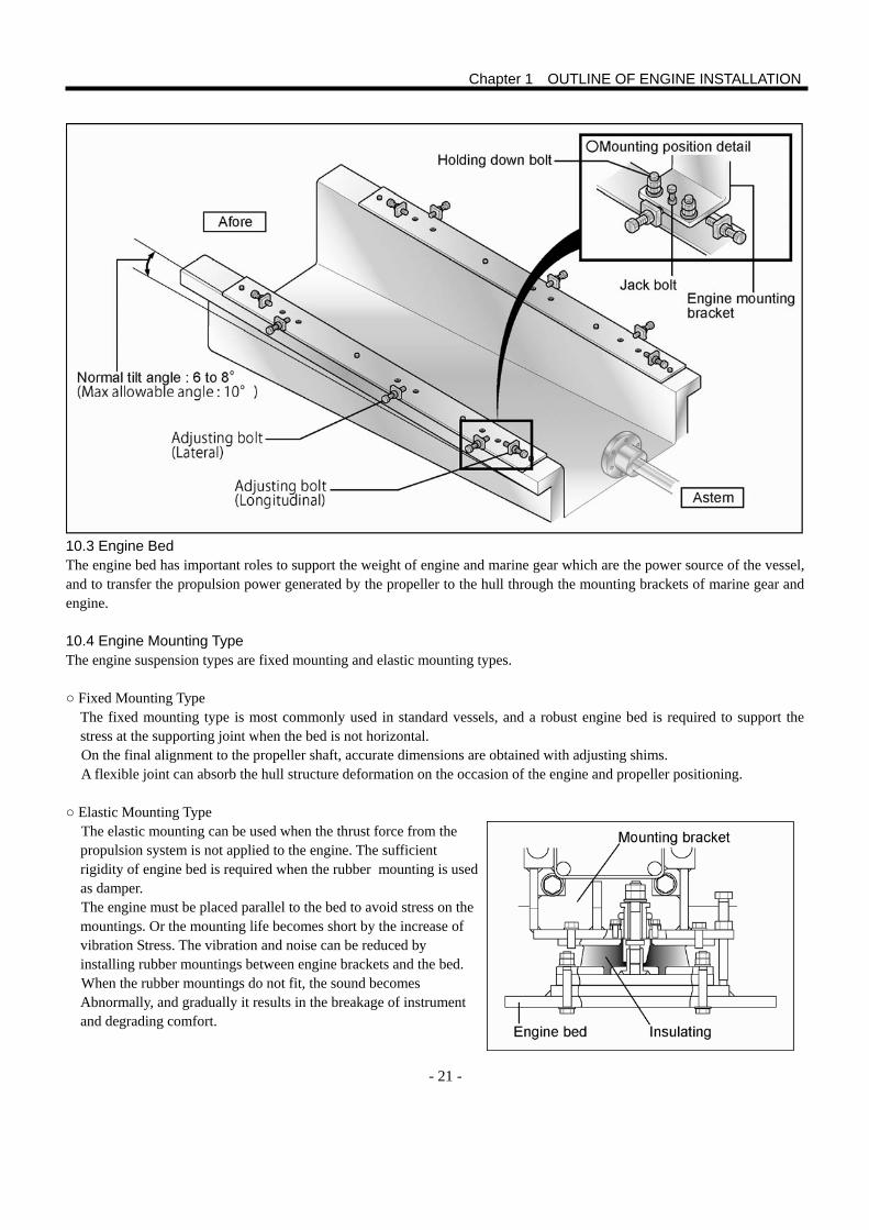
- 21 -
10.3 Engine Bed The engine bed has important roles to support the weight of engine and marine gear which are the power source of the vessel, and to transfer the propulsion power generated by the propeller to the hull through the mounting brackets of marine gear and engine. 10.4 Engine Mounting Type The engine suspension types are fixed mounting and elastic mounting types. ○ Fixed Mounting Type
The fixed mounting type is most commonly used in standard vessels, and a robust engine bed is required to support the stress at the supporting joint when the bed is not horizontal. On the final alignment to the propeller shaft, accurate dimensions are obtained with adjusting shims. A flexible joint can absorb the hull structure deformation on the occasion of the engine and propeller positioning.
○ Elastic Mounting Type
The elastic mounting can be used when the thrust force from the propulsion system is not applied to the engine. The sufficient rigidity of engine bed is required when the rubber mounting is used as damper. The engine must be placed parallel to the bed to avoid stress on the mountings. Or the mounting life becomes short by the increase of vibration Stress. The vibration and noise can be reduced by installing rubber mountings between engine brackets and the bed. When the rubber mountings do not fit, the sound becomes Abnormally, and gradually it results in the breakage of instrument and degrading comfort.
Chapter 1 OUTLINE OF ENGINE INSTALLATION
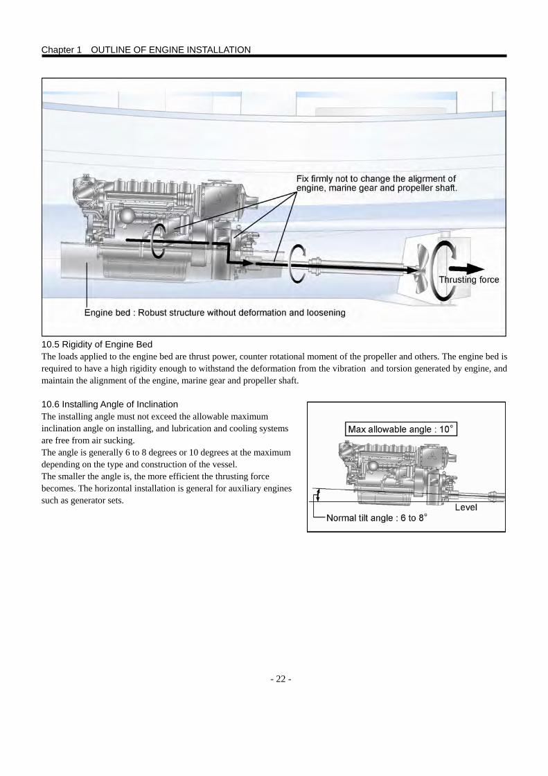
- 22 -
10.5 Rigidity of Engine Bed The loads applied to the engine bed are thrust power, counter rotational moment of the propeller and others. The engine bed is required to have a high rigidity enough to withstand the deformation from the vibration and torsion generated by engine, and maintain the alignment of the engine, marine gear and propeller shaft.
10.6 Installing Angle of Inclination The installing angle must not exceed the allowable maximum inclination angle on installing, and lubrication and cooling systems are free from air sucking. The angle is generally 6 to 8 degrees or 10 degrees at the maximum depending on the type and construction of the vessel. The smaller the angle is, the more efficient the thrusting force becomes. The horizontal installation is general for auxiliary engines such as generator sets.
Chapter 1 OUTLINE OF ENGINE INSTALLATION
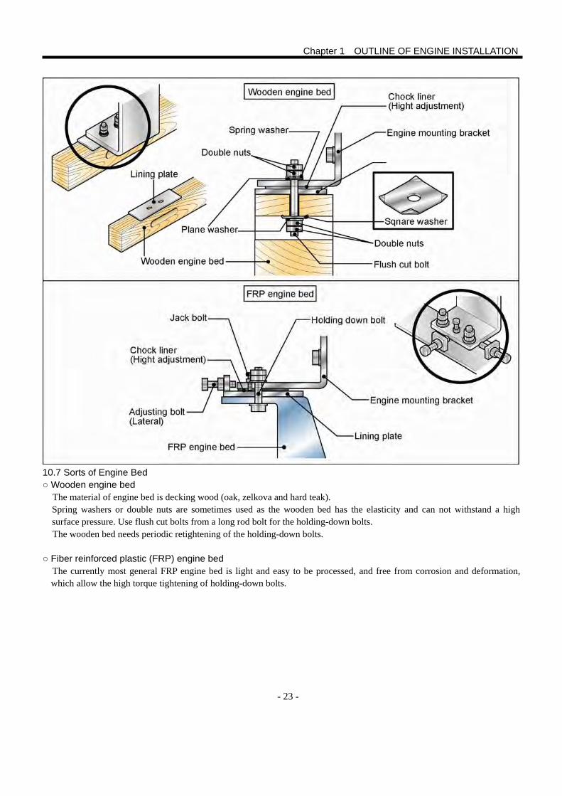
- 23 -
10.7 Sorts of Engine Bed ○ Wooden engine bed
The material of engine bed is decking wood (oak, zelkova and hard teak). Spring washers or double nuts are sometimes used as the wooden bed has the elasticity and can not withstand a high surface pressure. Use flush cut bolts from a long rod bolt for the holding-down bolts. The wooden bed needs periodic retightening of the holding-down bolts.
○ Fiber reinforced plastic (FRP) engine bed
The currently most general FRP engine bed is light and easy to be processed, and free from corrosion and deformation, which allow the high torque tightening of holding-down bolts.
Chapter 1 OUTLINE OF ENGINE INSTALLATION
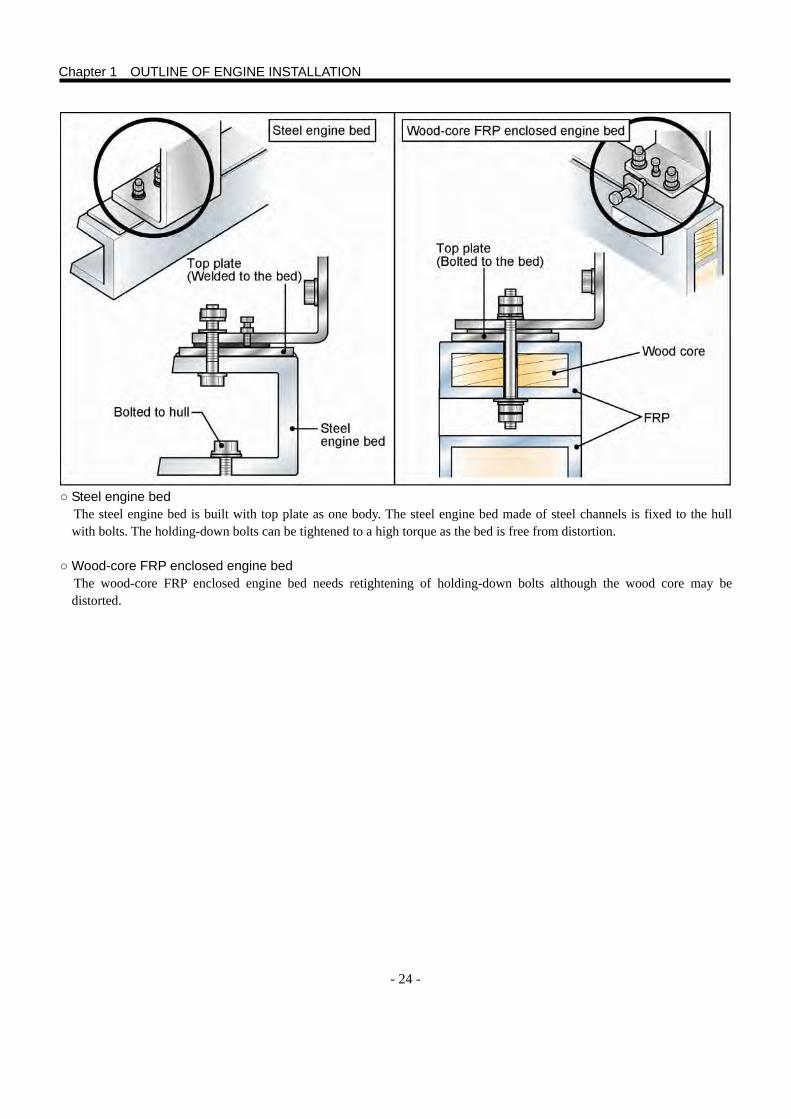
- 24 -
○ Steel engine bed
The steel engine bed is built with top plate as one body. The steel engine bed made of steel channels is fixed to the hull with bolts. The holding-down bolts can be tightened to a high torque as the bed is free from distortion.
○ Wood-core FRP enclosed engine bed
The wood-core FRP enclosed engine bed needs retightening of holding-down bolts although the wood core may be distorted.
Chapter 1 OUTLINE OF ENGINE INSTALLATION
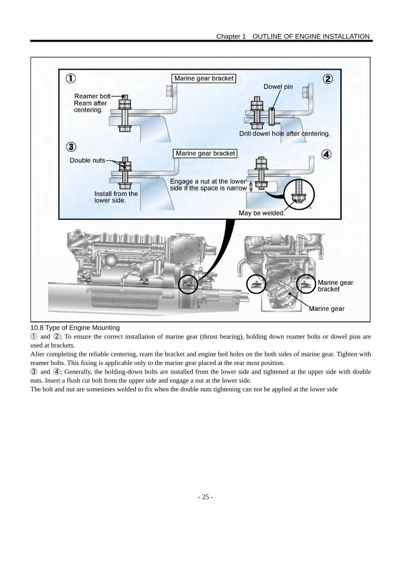
- 25 -
10.8 Type of Engine Mounting ① and ②; To ensure the correct installation of marine gear (thrust bearing), holding down reamer bolts or dowel pins are used at brackets. After completing the reliable centering, ream the bracket and engine bed holes on the both sides of marine gear. Tighten with reamer bolts. This fixing is applicable only to the marine gear placed at the rear most position. ③ and ④; Generally, the holding-down bolts are installed from the lower side and tightened at the upper side with double nuts. Insert a flush cut bolt from the upper side and engage a nut at the lower side. The bolt and nut are sometimes welded to fix when the double nuts tightening can not be applied at the lower side
Chapter 1 OUTLINE OF ENGINE INSTALLATION
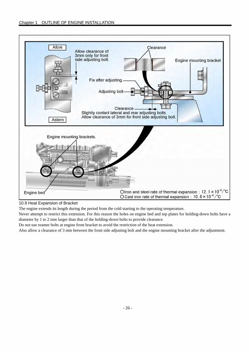
- 26 -
10.9 Heat Expansion of Bracket The engine extends its length during the period from the cold starting to the operating temperature. Never attempt to restrict this extension. For this reason the holes on engine bed and top plates for holding-down bolts have a diameter by 1 to 2 mm larger than that of the holding-down bolts to provide clearance. Do not use reamer bolts at engine front bracket to avoid the restriction of the heat extension. Also allow a clearance of 3 mm between the front side adjusting bolt and the engine mounting bracket after the adjustment.
Chapter 1 OUTLINE OF ENGINE INSTALLATION
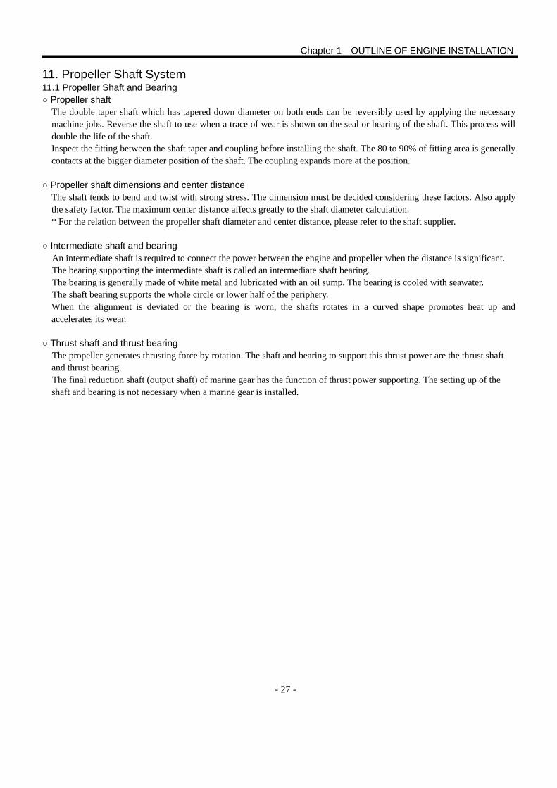
- 27 -
11. Propeller Shaft System 11.1 Propeller Shaft and Bearing ○ Propeller shaft The double taper shaft which has tapered down diameter on both ends can be reversibly used by applying the necessary
machine jobs. Reverse the shaft to use when a trace of wear is shown on the seal or bearing of the shaft. This process will double the life of the shaft. Inspect the fitting between the shaft taper and coupling before installing the shaft. The 80 to 90% of fitting area is generally contacts at the bigger diameter position of the shaft. The coupling expands more at the position.
○ Propeller shaft dimensions and center distance The shaft tends to bend and twist with strong stress. The dimension must be decided considering these factors. Also apply the safety factor. The maximum center distance affects greatly to the shaft diameter calculation.
* For the relation between the propeller shaft diameter and center distance, please refer to the shaft supplier.
○ Intermediate shaft and bearing An intermediate shaft is required to connect the power between the engine and propeller when the distance is significant. The bearing supporting the intermediate shaft is called an intermediate shaft bearing. The bearing is generally made of white metal and lubricated with an oil sump. The bearing is cooled with seawater. The shaft bearing supports the whole circle or lower half of the periphery. When the alignment is deviated or the bearing is worn, the shafts rotates in a curved shape promotes heat up and accelerates its wear.
○ Thrust shaft and thrust bearing The propeller generates thrusting force by rotation. The shaft and bearing to support this thrust power are the thrust shaft and thrust bearing. The final reduction shaft (output shaft) of marine gear has the function of thrust power supporting. The setting up of the shaft and bearing is not necessary when a marine gear is installed.
Chapter 1 OUTLINE OF ENGINE INSTALLATION
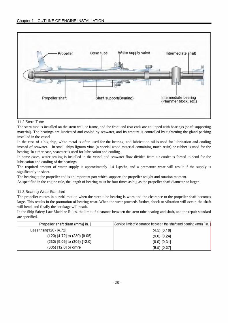
- 28 -
11.2 Stern Tube The stern tube is installed on the stern wall or frame, and the front and rear ends are equipped with bearings (shaft supporting material). The bearings are lubricated and cooled by seawater, and its amount is controlled by tightening the gland packing installed in the vessel. In the case of a big ship, white metal is often used for the bearing, and lubrication oil is used for lubrication and cooling instead of seawater. In small ships lignum vitae (a special wood material containing much resin) or rubber is used for the bearing. In either case, seawater is used for lubrication and cooling. In some cases, water sealing is installed in the vessel and seawater flow divided from air cooler is forced to send for the lubrication and cooling of the bearings. The required amount of water supply is approximately 1.4 L/ps·hr, and a premature wear will result if the supply is significantly in short. The bearing at the propeller end is an important part which supports the propeller weight and rotation moment. As specified in the engine rule, the length of bearing must be four times as big as the propeller shaft diameter or larger. 11.3 Bearing Wear Standard The propeller rotates in a swirl motion when the stern tube bearing is worn and the clearance to the propeller shaft becomes large. This results in the promotion of bearing wear. When the wear proceeds further, shock or vibration will occur, the shaft will bend, and finally the breakage will result. In the Ship Safety Law Machine Rules, the limit of clearance between the stern tube bearing and shaft, and the repair standard are specified.
Chapter 1 OUTLINE OF ENGINE INSTALLATION
- 29 -
1. Centering Procedure 1.1 Centering Procedure with Leveling Line The leveling line centering procedure is briefly described below. 1 Place a leveling line through the stern tube (inside of the vessel) with a guide stick. 2 Open a hole in the center of a wood piece, place the line end of outside of the vessel through the hole and fix the line not to
become loose. Attach the piece at the end of stern tube outside of the vessel. Wind the other end of the line around a bent nail, and stretch the line from the outside end of the stern tube through the center of tube to the bow side bulkhead.
3 Measure the line position in the tube with an inner compass. 4 Tap the bent nail with hammer to finely adjust the line to be at the center of the tube.
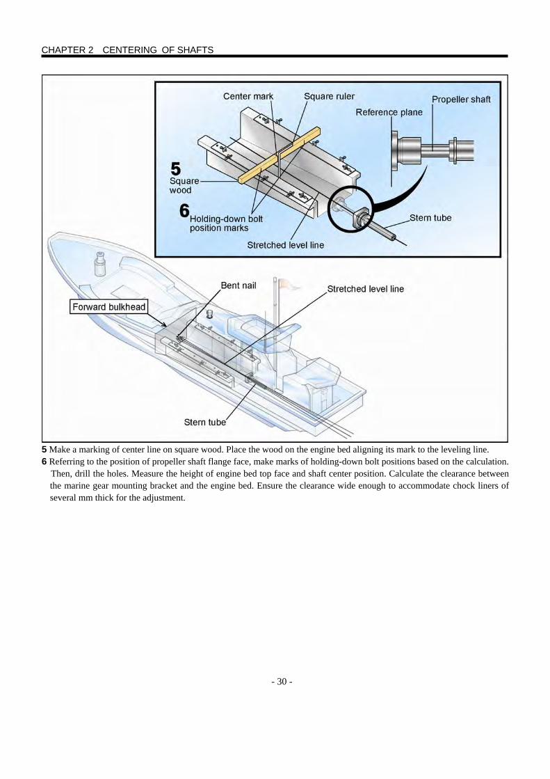
- 30 -
5 Make a marking of center line on square wood. Place the wood on the engine bed aligning its mark to the leveling line. 6 Referring to the position of propeller shaft flange face, make marks of holding-down bolt positions based on the calculation. Then, drill the holes. Measure the height of engine bed top face and shaft center position. Calculate the clearance between
the marine gear mounting bracket and the engine bed. Ensure the clearance wide enough to accommodate chock liners of several mm thick for the adjustment.
CHAPTER 2 CENTERING OF SHAFTS
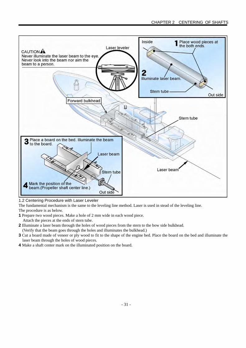
- 31 -
1.2 Centering Procedure with Laser Leveler The fundamental mechanism is the same to the leveling line method. Laser is used in stead of the leveling line. The procedure is as below. 1 Prepare two wood pieces. Make a hole of 2 mm wide in each wood piece. Attach the pieces at the ends of stern tube. 2 Illuminate a laser beam through the holes of wood pieces from the stern to the bow side bulkhead.
(Verify that the beam goes through the holes and illuminates the bulkhead.) 3 Cut a board made of veneer or ply wood to fit to the shape of the engine bed. Place the board on the bed and illuminate the
laser beam through the holes of wood pieces. 4 Make a shaft center mark on the illuminated position on the board.
CHAPTER 2 CENTERING OF SHAFTS
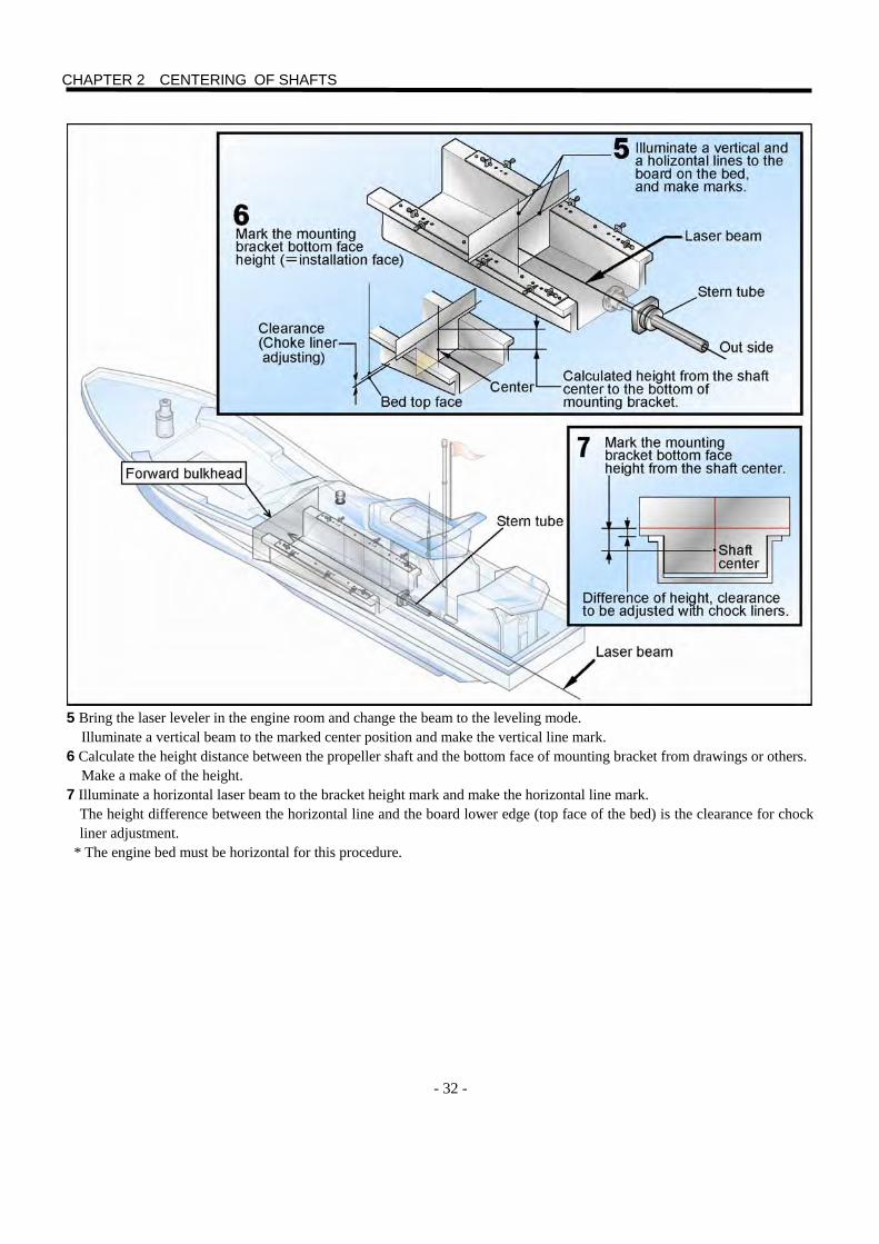
- 32 -
5 Bring the laser leveler in the engine room and change the beam to the leveling mode. Illuminate a vertical beam to the marked center position and make the vertical line mark. 6 Calculate the height distance between the propeller shaft and the bottom face of mounting bracket from drawings or others. Make a make of the height. 7 Illuminate a horizontal laser beam to the bracket height mark and make the horizontal line mark.
The height difference between the horizontal line and the board lower edge (top face of the bed) is the clearance for chock liner adjustment.
* The engine bed must be horizontal for this procedure.
CHAPTER 2 CENTERING OF SHAFTS
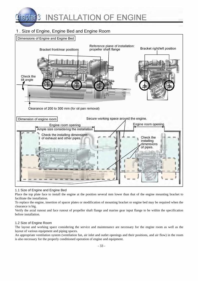
- 33 -
1. Size of Engine, Engine Bed and Engine Room 1.1 Size of Engine and Engine Bed Place the top plate face to install the engine at the position several mm lower than that of the engine mounting bracket to facilitate the installation. To replace the engine, insertion of spacer plates or modification of mounting bracket or engine bed may be required when the clearance is big. Verify the axial runout and face runout of propeller shaft flange and marine gear input flange to be within the specification before installation.
1.2 Size of Engine Room The layout and working space considering the service and maintenance are necessary for the engine room as well as the layout of various equipment and piping spaces. An appropriate ventilation system (ventilation fan, air inlet and outlet openings and their positions, and air flow) in the room is also necessary for the properly conditioned operation of engine and equipment.
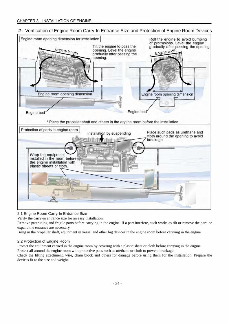
- 34 -
2.Verification of Engine Room Carry-In Entrance Size and Protection of Engine Room Devices 2.1 Engine Room Carry-In Entrance Size Verify the carry-in entrance size for an easy installation. Remove protruding and fragile parts before carrying in the engine. If a part interfere, such works as tilt or remove the part, or expand the entrance are necessary. Bring in the propeller shaft, equipment in vessel and other big devices in the engine room before carrying in the engine. 2.2 Protection of Engine Room Protect the equipment carried in the engine room by covering with a plastic sheet or cloth before carrying in the engine. Protect all around the engine room with protective pads such as urethane or cloth to prevent breakage. Check the lifting attachment, wire, chain block and others for damage before using them for the installation. Prepare the devices fit to the size and weight.
CHAPTER 3 INSTALLATION OF ENGINE
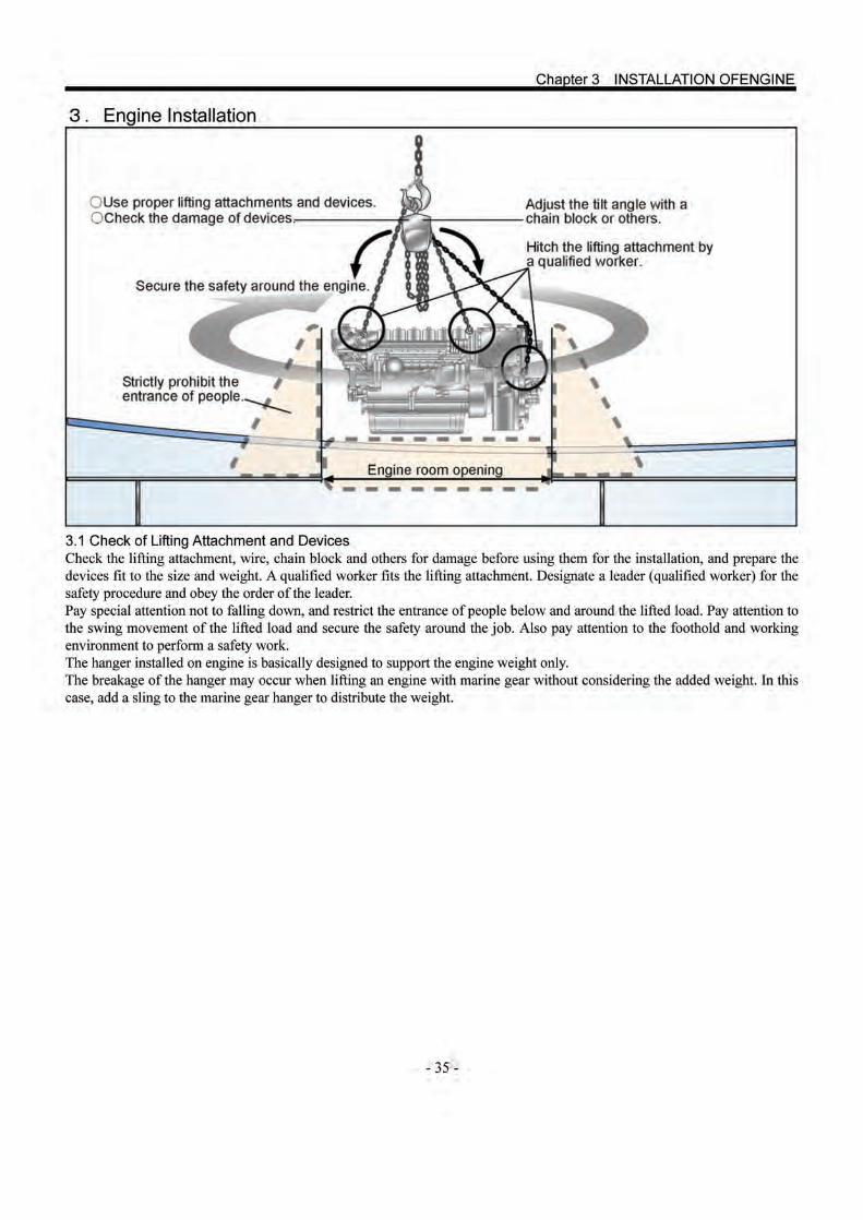

- 36 -
4.Provisional Positioning on Engine Bed 4.1 Provisional Positioning Check the lifting attachment and lifting positions before lifting the engine. Prevent water and oil from dripping before lean the engine to install. Prepare drip pans and wipe off the spill immediately after dripping. Slowly carry in the engine under the supervision of the leader. Place the engine provisionally near the holding-down bolts. 4.2 Preparation of Adjusting Bolt Block Remove the lifting attachment after placing the engine. Weld the adjusting bolt blocks for front/rear and right /left adjustment after verifying the adjusting clearance. Pay attention to the grounding position and spatter fly-off. Usually the engine is directly positioned on the top plate of engine bed in the case of a new vessel. In the case of engine replacement, spacers (steel plates) are inserted for the height adjustment to mount the new engine.
Chapter 3 INSTALLATION OF ENGINE
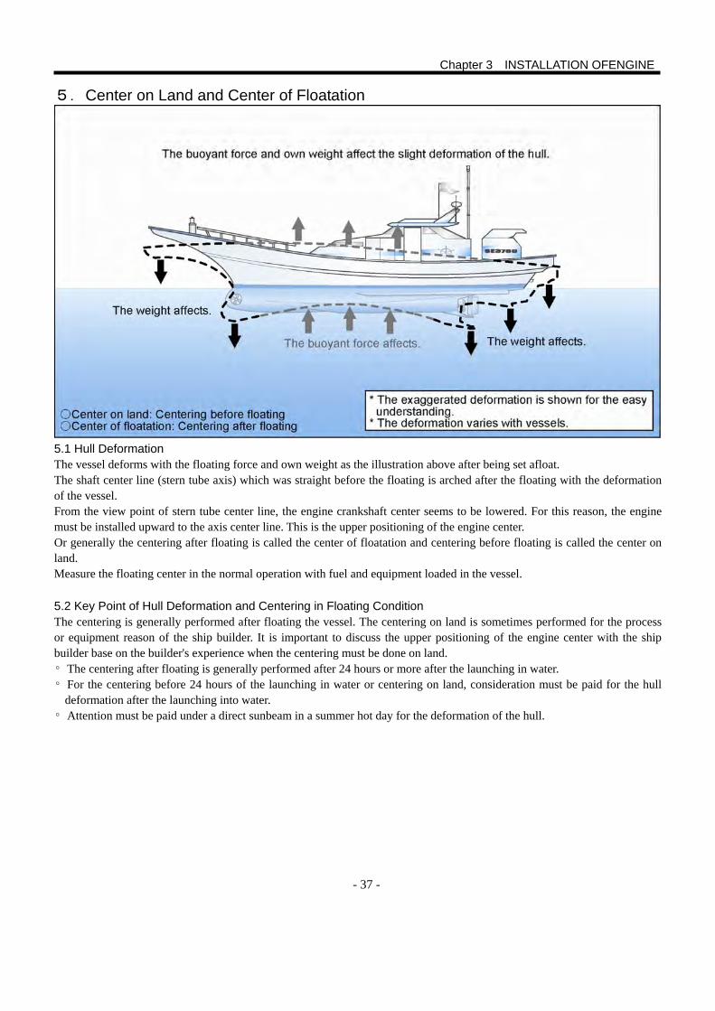
- 37 -
5.Center on Land and Center of Floatation 5.1 Hull Deformation The vessel deforms with the floating force and own weight as the illustration above after being set afloat. The shaft center line (stern tube axis) which was straight before the floating is arched after the floating with the deformation of the vessel. From the view point of stern tube center line, the engine crankshaft center seems to be lowered. For this reason, the engine must be installed upward to the axis center line. This is the upper positioning of the engine center. Or generally the centering after floating is called the center of floatation and centering before floating is called the center on land. Measure the floating center in the normal operation with fuel and equipment loaded in the vessel. 5.2 Key Point of Hull Deformation and Centering in Floating Condition The centering is generally performed after floating the vessel. The centering on land is sometimes performed for the process or equipment reason of the ship builder. It is important to discuss the upper positioning of the engine center with the ship builder base on the builder's experience when the centering must be done on land. ◦ The centering after floating is generally performed after 24 hours or more after the launching in water. ◦ For the centering before 24 hours of the launching in water or centering on land, consideration must be paid for the hull
deformation after the launching into water. ◦ Attention must be paid under a direct sunbeam in a summer hot day for the deformation of the hull.
Chapter 3 INSTALLATION OFENGINE
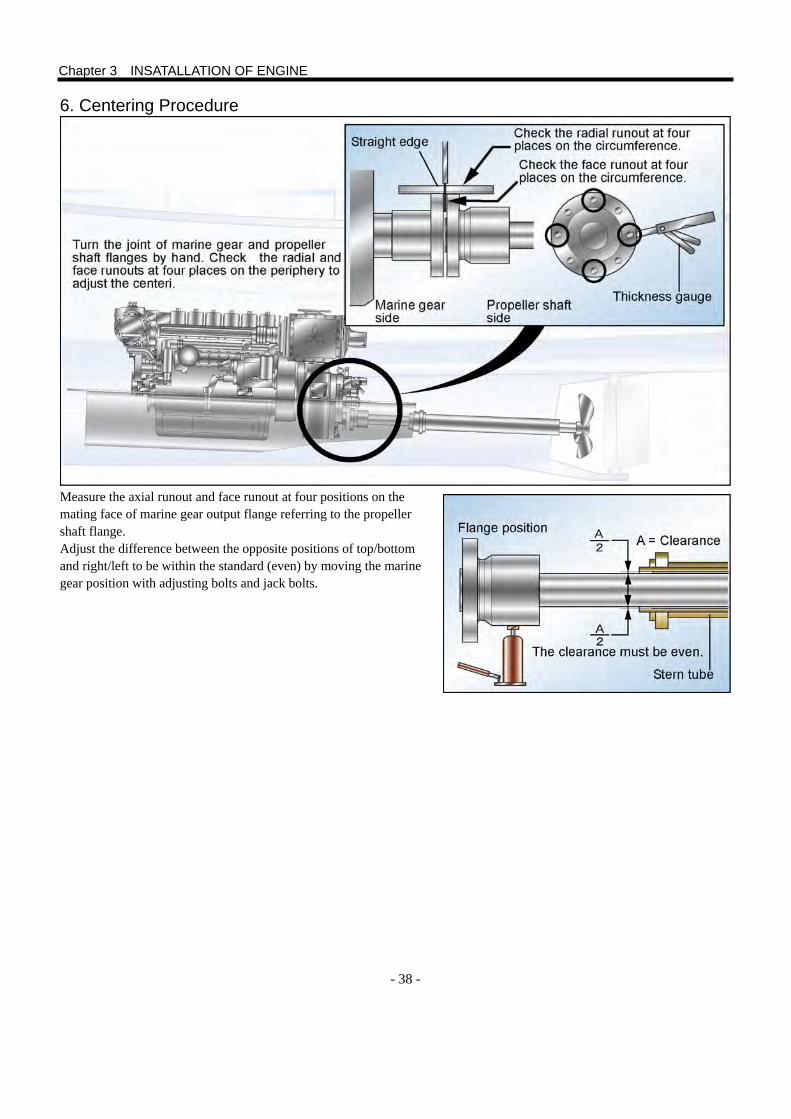
- 38 -
6. Centering Procedure Measure the axial runout and face runout at four positions on the mating face of marine gear output flange referring to the propeller shaft flange. Adjust the difference between the opposite positions of top/bottom and right/left to be within the standard (even) by moving the marine gear position with adjusting bolts and jack bolts.
Chapter 3 INSATALLATION OF ENGINE
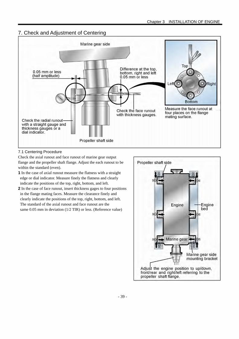
- 39 -
7. Check and Adjustment of Centering
7.1 Centering Procedure Check the axial runout and face runout of marine gear output flange and the propeller shaft flange. Adjust the each runout to be within the standard (even). 1 In the case of axial runout measure the flatness with a straight edge or dial indicator. Measure finely the flatness and clearly indicate the positions of the top, right, bottom, and left.
2 In the case of face runout, insert thickness gages to four positions in the flange mating faces. Measure the clearance finely and clearly indicate the positions of the top, right, bottom, and left. The standard of the axial runout and face runout are the same 0.05 mm in deviation (1/2 TIR) or less. (Reference value)
Chapter 3 INSTALLATION OF ENGINE
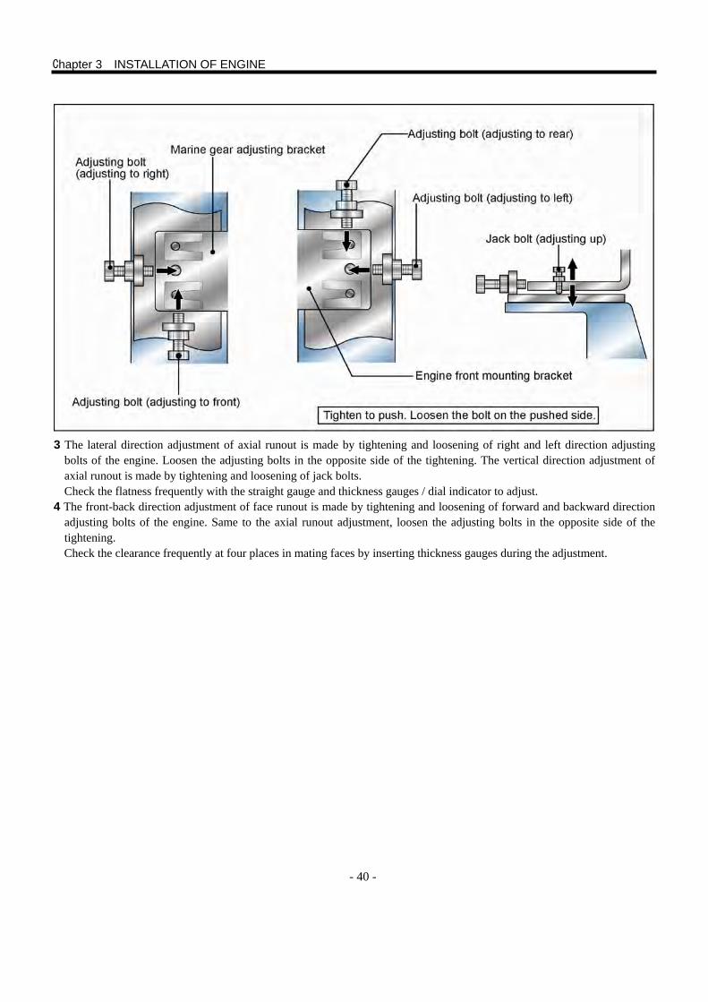
- 40 -
3 The lateral direction adjustment of axial runout is made by tightening and loosening of right and left direction adjusting
bolts of the engine. Loosen the adjusting bolts in the opposite side of the tightening. The vertical direction adjustment of axial runout is made by tightening and loosening of jack bolts. Check the flatness frequently with the straight gauge and thickness gauges / dial indicator to adjust.
4 The front-back direction adjustment of face runout is made by tightening and loosening of forward and backward direction adjusting bolts of the engine. Same to the axial runout adjustment, loosen the adjusting bolts in the opposite side of the tightening. Check the clearance frequently at four places in mating faces by inserting thickness gauges during the adjustment.
Chapter 3 INSTALLATION OF ENGINE
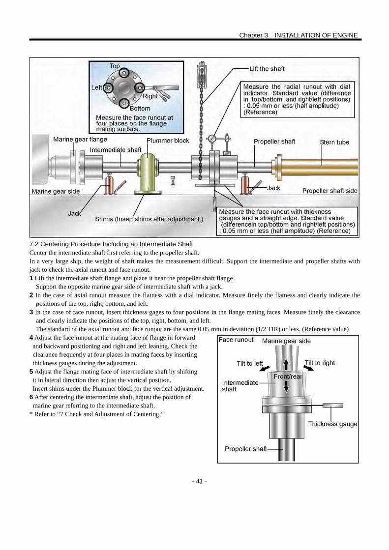
- 41 -
7.2 Centering Procedure Including an Intermediate Shaft Center the intermediate shaft first referring to the propeller shaft. In a very large ship, the weight of shaft makes the measurement difficult. Support the intermediate and propeller shafts with jack to check the axial runout and face runout. 1 Lift the intermediate shaft flange and place it near the propeller shaft flange.
Support the opposite marine gear side of intermediate shaft with a jack. 2 In the case of axial runout measure the flatness with a dial indicator. Measure finely the flatness and clearly indicate the
positions of the top, right, bottom, and left. 3 In the case of face runout, insert thickness gages to four positions in the flange mating faces. Measure finely the clearance
and clearly indicate the positions of the top, right, bottom, and left. The standard of the axial runout and face runout are the same 0.05 mm in deviation (1/2 TIR) or less. (Reference value)
4 Adjust the face runout at the mating face of flange in forward and backward positioning and right and left leaning. Check the clearance frequently at four places in mating faces by inserting thickness gauges during the adjustment.
5 Adjust the flange mating face of intermediate shaft by shifting it in lateral direction then adjust the vertical position. Insert shims under the Plummer block for the vertical adjustment.
6 After centering the intermediate shaft, adjust the position of marine gear referring to the intermediate shaft.
* Refer to “7 Check and Adjustment of Centering.”
Chapter 3 INSTALLATION OF ENGINE
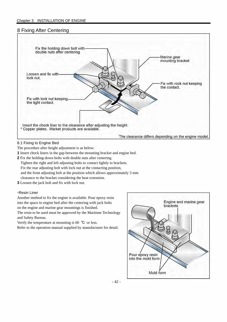
- 42 -
8 Fixing After Centering
8.1 Fixing to Engine Bed The procedure after height adjustment is as below: 1 Insert chock liners in the gap between the mounting bracket and engine bed. 2 Fix the holding-down bolts with double nuts after centering.
Tighten the right and left adjusting bolts to contact lightly to brackets. Fix the rear adjusting bolt with lock nut at the contacting position, and the front adjusting bolt at the position which allows approximately 3 mm clearance to the bracket considering the heat extension.
3 Loosen the jack bolt and fix with lock nut. ◦Resin Liner Another method to fix the engine is available. Pour epoxy resin into the space to engine bed after the centering with jack bolts on the engine and marine gear mountings is finished. The resin to be used must be approved by the Maritime Technology and Safety Bureau. Verify the temperature at mounting is 60 ℃ or less. Refer to the operation manual supplied by manufacturer for detail.
Chapter 3 INSTALLATION OF ENGINE
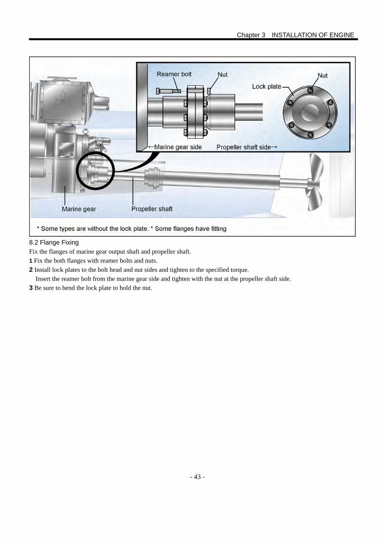
- 43 -
8.2 Flange Fixing Fix the flanges of marine gear output shaft and propeller shaft. 1 Fix the both flanges with reamer bolts and nuts. 2 Install lock plates to the bolt head and nut sides and tighten to the specified torque. Insert the reamer bolt from the marine gear side and tighten with the nut at the propeller shaft side. 3 Be sure to bend the lock plate to hold the nut.
Chapter 3 INSTALLATION OF ENGINE
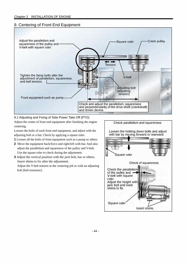
- 44 -
9. Centering of Front End Equipment 9.1 Adjusting and Fixing of Side Power Take Off (PTO) Adjust the center of front end equipment after finishing the engine centering. Loosen the bolts of each front end equipment, and adjust with the adjusting bolt or a bar. Check by applying a square ruler. 1 Loosen all the bolts of front equipment such as a pump or others. 2 Move the equipment back/force and right/left with bar. And also
adjust the parallelism and squareness of the pulley and V-belt. Use the square ruler to check during the adjustment.
3 Adjust the vertical position with the jack bolt, bar or others. Insert shims to fix after the adjustment. Adjust the V-belt tension in the centering job or with an adjusting bolt (belt tensioner).
Chapter 3 INSTALLATION OF ENGINE
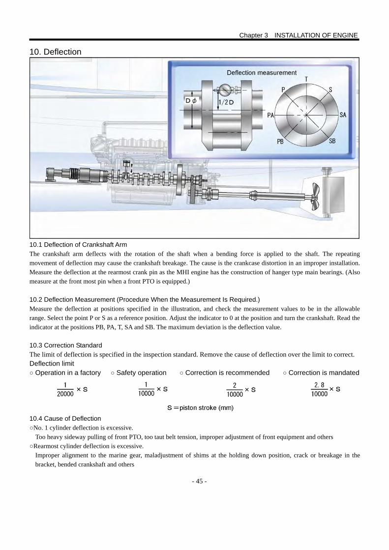
- 45 -
10. Deflection 10.1 Deflection of Crankshaft Arm The crankshaft arm deflects with the rotation of the shaft when a bending force is applied to the shaft. The repeating movement of deflection may cause the crankshaft breakage. The cause is the crankcase distortion in an improper installation. Measure the deflection at the rearmost crank pin as the MHI engine has the construction of hanger type main bearings. (Also measure at the front most pin when a front PTO is equipped.) 10.2 Deflection Measurement (Procedure When the Measurement Is Required.) Measure the deflection at positions specified in the illustration, and check the measurement values to be in the allowable range. Select the point P or S as a reference position. Adjust the indicator to 0 at the position and turn the crankshaft. Read the indicator at the positions PB, PA, T, SA and SB. The maximum deviation is the deflection value. 10.3 Correction Standard The limit of deflection is specified in the inspection standard. Remove the cause of deflection over the limit to correct. Deflection limit ○ Operation in a factory ○ Safety operation ○ Correction is recommended ○ Correction is mandated
10.4 Cause of Deflection ○No. 1 cylinder deflection is excessive.
Too heavy sideway pulling of front PTO, too taut belt tension, improper adjustment of front equipment and others ○Rearmost cylinder deflection is excessive.
Improper alignment to the marine gear, maladjustment of shims at the holding down position, crack or breakage in the bracket, bended crankshaft and others
Chapter 3 INSTALLATION OF ENGINE
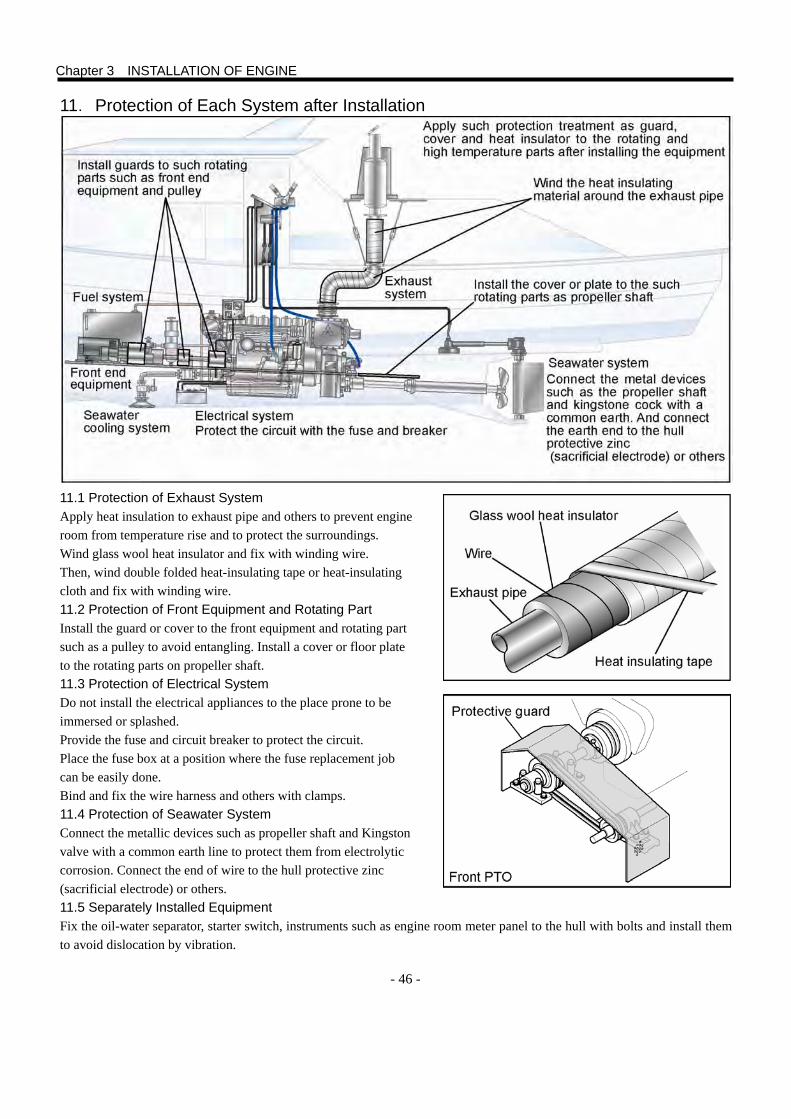
- 46 -
11.Protection of Each System after Installation 11.1 Protection of Exhaust System Apply heat insulation to exhaust pipe and others to prevent engine room from temperature rise and to protect the surroundings. Wind glass wool heat insulator and fix with winding wire. Then, wind double folded heat-insulating tape or heat-insulating cloth and fix with winding wire. 11.2 Protection of Front Equipment and Rotating Part Install the guard or cover to the front equipment and rotating part such as a pulley to avoid entangling. Install a cover or floor plate to the rotating parts on propeller shaft. 11.3 Protection of Electrical System Do not install the electrical appliances to the place prone to be immersed or splashed. Provide the fuse and circuit breaker to protect the circuit. Place the fuse box at a position where the fuse replacement job can be easily done. Bind and fix the wire harness and others with clamps. 11.4 Protection of Seawater System Connect the metallic devices such as propeller shaft and Kingston valve with a common earth line to protect them from electrolytic corrosion. Connect the end of wire to the hull protective zinc (sacrificial electrode) or others. 11.5 Separately Installed Equipment Fix the oil-water separator, starter switch, instruments such as engine room meter panel to the hull with bolts and install them to avoid dislocation by vibration.
Chapter 3 INSTALLATION OF ENGINE
- 47 -
1. Outline The fuel cost takes the most part of engine operational cost. And the fuel property affects largely the engine performance and life. Also many components composing the fuel system, besides the engine mounted ones, are installed in an engine room. The proper knowledge of function and construction of these components is essential for the planning of installation.
2. Fuel General 2.1 Fuel Properties and Composition Affecting the Engine Trouble If the fuel properties are designated by maritime emission regulations in each country, obey the regulations. Even in this case, make sure the required performance specified for the degradation of lubricity caused by the reduction of fuel sulfur content.
A low grade fuel is often used for marine engines when the emission regulation is not applied. In this case, the use of a fuel having MHI recommended properties is specified. Especially in the maritime market, low grade fuel with high sulfur contents is widely used. Consideration is necessary for the sulfur content and the fuel quality to be used. If the sulfur content is 0.2% or more, use the fuel which conforms to the [Limit of Fuel Property] on P53.
2.2 Flash Point The flash point is a temperature where the fuel vapor ignites when an open flame or fire is applied. It is an indication of volatility for the safety handling of the fuel. It also indicates the light distillates and, however, is not directly related to the engine performance.
2.3 Distillation Characteristics A low initial boiling point temperature shows the inclusion of light oil which results in the increase thermal load on piston and valve mechanism caused by the ignition retard, after burning and detonation (diesel knock). A high temperature of 90 % distillate temperature shows the inclusion of heavy oil which results in the wear of cylinder liner and piston ring caused by the retarded combustion, incomplete combustion and increased amount of soot.
2.4 Pour Point (PP) The fuel stops its flowing by its own weight when its temperature is lowered to an extent. The flow stopping temperature is the pour point and shown in a integer multiple number of 2.5 ℃. When the temperature of fuel becomes the pour point or lower, the gravitational supply of fuel from a main tank or a daily tank stops or becomes insufficient. A fuel with its pour point temperature is higher than the ambient temperature results in a difficulty of starting or loaded operation.
2.5 Cloud Point (CP) Wax is an indispensable component to ensure the cetane number. The CP is a temperature where wax starts to crystallize (to appear as cloud or mist) as the wax is dissolved in the fuel in a room temperature. At the CP temperature the crystal is not yet solid wax, and will not cause the filter clogging. For this reason, the filter clogging management referring the CP is a safe way.
2.6 Cold Filter Plugging Point (CFPP) From an international view point for the effective utilization of oil resources, the production of middle distillate has been increased, and the flow improver, which retards the crystallization of wax to prevent the filter from plugging, is begun to be used. In this trend of heavier diesel fuel, the CFPP is newly specified to avoid the troubles in a low temperature. Generally the FPP temperature is approximately 3 ℃ lower than the CP temperature.
- 48 -
2.7 Carbon Residue (10% Residual Oil) The carbon residue is shown as a weight ratio of the remained dried carbon and the original fuel after evaporating 90 % of the fuel and thermally decomposing the remaining 10 %. This includes the carbon originally mixed. The fuel oil (A: JIS K2205) in Japan contains less carbon residue compared with diesel fuel in foreign countries. To cope with the oil resource depletion, the grade of the fuel has been yearly degrading and the carbon residue has been increasing. Significant amount of the carbon residue degrades the exhaust smoke, causes deposits in the injection nozzle and combustion chamber, and can result in the piston ring seizure. Especially, the solid carbon mixed in fuel causes nozzle orifice clogging or wear, and fuel filter clogging in an short period of time. The mixing of deposits such as soot into lubrication oil rapidly degrades the oil, and an early replacement of the oil is required.
2.8 Cetane Number The cetane number is an indication of the self-ignition tendency of the fuel. In the case of diesel fuel, the spontaneously igniting temperature in the raised fuel temperature is lower than that of gasoline. In the case of diesel engine in which the fuel is ignited with compressed heat of air, the cetane number, which indicates the self-ignition performance, is the most important property among many other properties. The cetane number is assessed with an anti-knocking standard fuel in the comparative test. The standard fuel is a mixture of cetane (cetane number: 100) which has rather high anti-knocking property, and hepta methyl nonan (cetane number: 15) of low knocking property. The volume ratio of the mixture which shows the same anti-knock performance with the test fuel is specified as the cetane number of the test fuel. If the cetane number is low, evaporating constituent in the fuel is high and the compression temperature is lowered by the high evaporation. This results in a poor ignitability, worsened startability in a cold temperature and increased amount of white smoke in a low idling operation.
2.9 Cetane Index In contrast to the measured cetane number, the cetane index is calculated from the distillation temperature and API specific gravity of the fuel. The measurement of the cetane number requires a high cost to request the comparison test of combustion characteristic to a specialized institute. For this reason, fuel suppliers tend to avoid the measurement of cetane number for the low priced diesel fuels. As a result, the fuel oil (A: JIS K2205) for the Japanese market uses the cetane index instead of the cetane number. The cetane index is calculated from the 50% distillate temperature and the specific gravity. Use the new calculation formula of JIS K2208-1996 or ISO 4264-1995 which shows a close value to the catane number. The old calculation formula of JIS K2204-1992 or ASTM D976-1966 is sometimes used. Pay attention not to use these formulae as the result is far from the cetane number (higher than the cetane number).
2.10 Kinetic Viscosity The viscosity, which shows a resistance to the fuel flow, has a close relation to the fuel splay and affects the combustion performance. When the kinetic viscosity is very high, the fuel filteration is degraded and the air bleeding in fuel system becomes difficult. When the viscosity is low, a lubrication defect may occur at the sliding faces between the plunger and barrel in injection pump or between the nozzle needle and holder in injection nozzle which are lubricated by the fuel.
Chapter 4 FUEL SYSTEM
- 49 -
2.11 Sulfur (High Sulfur Content Fuel) Sulfur dioxide formed in the combustion of sulfur content reacts with moisture in exhaust gas during an engine low-load operation and forms sulfuric acid which corrodes the cylinder liners, piston rings and nozzle tips. When the lubrication oil oxidization is progressed and the base number to neutralize the oil is reduced, the shafts and bearings will be corroded. And in the high-load operation, sulfur oxides formed in the combustion generates insoluble sludge and the incomplete fuel combustion generates soot. The sludge and soot mixed in the lubrication oil accumulate in the piston ring grooves and around the exhaust valves as the combustion deposit with fuel impurities. This results in the seizure of piston ring, defective sliding of exhaust valve or exhaust gas blow-by intruding between the valve and valve seat ring. In the fuel properties, especially the sulfur content largely affects the life of lubrication oil. It is recommended to analyze the lubrication oil and to know the degrading condition of the oil. The fuel with high sulfur content generates much amount of sulfur dioxide (sulfurous acid gas) in the combustion. Lubrication oil having a high total basic number with high neutralizing capability is needed against the sulfur dioxide mixing into the lubrication oil. The 0.2 % sulfur content of the used fuel is a threshold of quality grade of recommended engine lubrication oil.
2.12 Desulfurized Diesel Fuel, Ultra-Low Sulfur Diesel Fuel The lubrication performance of diesel fuel is degraded with desulfurization, and the plunger wear in fuel injection system and others will be affected. Especially in a precision-make high-pressure injection system such as a common rail system the durability will largely be affected. For this reason, when a low sulfur content fuel (0.2 weight % sulfur or less) is used in the MHI engine, the result of lubrication performance test with the high frequency reciprocating rig (HFRR) must show that the wear trace diameter of steel balls is 460 μm or less.
2.13 Water Content The water content in fuel causes wear and corrosion of the fuel injection system parts, sticking of the sliding faces in fuel pump and nozzle, and break of the spring in a short period caused by small corrosion cavities on the spring surface. When the water content is much, the oil-water separator may be over flowed and the passing-through water will cause defects such as filter element premature clogging. For this reason, the procurement of clean fuel and consideration of storing and piping for the fuel are required. In some cases, the space in fuel tank and piping, allowed the condensation of vapor in air.
2.14 Sediment The fuel, which was carried in a contaminated tank truck after a low grade oil delivery of the truck or stored in a contaminated fuel tank, causes the wear of injection system parts, injection nozzle stick and premature clogging of fuel filter. Un-burnt sediment forms sludge and rapidly contaminates the lubrication oil.
2.15 Ash Ash consists of metals and other contaminants. It forms the gray-brown deposit on the combustion system parts such as pistons and valves as it is an incombustible substance. For this reason, ash accelerates the sliding face wear of piston ring, cylinder liner, inlet valve and turbocharger. It also wears the sliding faces of injection system.
2.16 Copper Plate Corrosion Test The copper corrosion test indicates the corrosion behavior of the fuel against copper, brass and bronze. The corrosion behavior is based on the corrosive sulfur contained in the fuel. The discoloration of copper plate after the test is compared to the standard colors of copper plate corrosion. The color number is used as an indication of the corrosive behavior of the fuel. 2.17 Coking Thermal cracking test of the fuel is made for evaluation. A fuel which contains much tar or dry carbide tends to cause the seizure of fuel nozzle and the carbon deposit in combustion chamber.
Chapter 4 FUEL SYSTEM
- 50 -
2.18 Aromatics Aromatics are poor in ignitability, and cause the starting trouble and white smoke. The aromatics are components which have a characteristic fume called aroma. Aromatics are one of the causes of low cetane number, and may cause the valve stem sticking by retarding the combustion and increasing the exhaust temperature. Reclaimed light oil is of aromatics and one of materials used in low grade diesel fuels. When a fuel has a high specific gravity and low cetane number, it is thought to contain much amount of aromatics. 2.19 Asphaltene Asphaltene is a component of asphalt and a blackish brown solid or semisolid containing much sulfur, oxygen and nitrogen. It is flame resistant and tends to produce unburned carbon and soot. This results in the increase of combustion chamber deposit, and the wear of piston rings and liners. This can also be a cause of sticking of the fuel injection pump plunger and the fuel injection nozzle. A much amount of asphaltene causes the fuel filter clogging. Sometimes it contains heavy metals such as vanadium and nickel. The distillated fuel does not contain the asphaltene, but a fuel mixed with low grade oil sometimes contains it. 2.20 Impurities Miniaturized rust generated in the outer fuel system and others become impurities. When the impurities go through the fuel filter and entered the combustion chamber, scuffing of piston ring and cylinder liner may occur in some very extreme cases. 2.21 Lubrication Performance of Fuel (Indicated by the Wear Trace Diameter in HFRR Wear Tester) The lubrication performance is indicated by the wear scar diameter (measured mean wear scar diameter: MWSD) in μm unit. The trace is generated by contacting the test disk and test steel ball immersed in a fuel of 60 ℃ in the controlled condition of the high frequency reciprocating rig (HFRR). After the humidity correction of wear diameter in the standard vapor pressure condition of 1.4 kPa (10.5 mmHg), the wear scar diameter is used for the indication of lubrication performance of the fuel. 2.22 BDF: Bio-Diesel Fuel (Fatty Acid Methyl Ester: FAME) This is a plant-derived fuel to reduce the oil consumption and carbon dioxide generation. The use of the fuel mixed with the conventional diesel fuel is spreading for a low level of the adverse effect to engines. Currently, 5 % mixture in diesel fuel is accepted in Japan and foreign countries, and the use is already in practical use. The accepted fuel to mix is the bio-diesel fuel which satisfies the FAME 100% standard. It must comply with the quality standards such as EN14214 in EU, ASTM D6751 in US or JIS K2390 in Japan. With the mixing of bio-diesel fuel, such problems as water resulted from oxidation degradation, corrosion of metal and rubber, higher cold filter plugging point or impurity inclusion cause by material or processing may occur. Also the variety of material affects differently. It is essential to know the material and mixed percentage of BDF to cope with a problem. When the mixing rate is high, add diesel fuel to dilute the BDF and consume with out delay to avoid a prolonged period of storage. 2.23 Vanadium, Nickel and Sodium If these substances are included in the fuel, high temperature parts around combustion chamber corrode in a short period. Especially it will cause a rapid wear of exhaust valve and seat ring, exhaust gas leak out, defective sealing of injection nozzle and contamination of turbocharger. The distillated fuel does not contain the metals, but a fuel mixed with low grade oil sometimes contains them. However the level of content is negligible and MHI does not specify the limit value. 2.24 Salt Content In the case of salt inclusion in fuel, sodium, which is the main constituent of salt and highly corrosive, breaks the springs of fuel injection pump and fuel injection nozzle. Also, it wears the plunge and barrel of injection pump, and can be a cause of sludge accumulation in the piton ring groove. With a cause during the fuel storage, salt can enter the fuel from environment.
Chapter 4 FUEL SYSTEM
- 51 -
3. MHI Recommended Fuel for Engine (1) [Recommended fuel standard] on P52 shows the recommended fuel standard in each country for the engines not to be
controlled by the exhaust regulations. Fuels complying with the standard can be used for MHI large size diesel engines. (2) [Limit of fuel property] on P53 shows the limit value of properties for the fuel of MHI large size diesel engines.
The properties of fuel must satisfy the values in table. The lower the price of fuel is, the lower the quality is. Many properties do not meet the requirements, and the consideration of troubles is needed.
3.1 Fuel Oil (A: JIS K2205) Sold in Japanese Market (1) The fuel oil (A: JIS K2205) is sold in Japanese market only. It is not available in foreign countries.
The category 1 of JIS K2205 is proper for the fuel oil A. And the JIS does not specify the cetane number and others. For other property items, the required quality standards are not sufficient for the fuel of MHI diesel engines. And the quality values specified in JIS K2206 over the MHI recommended values. However, the fuel oil A of many renowned brands distributed in Japan may satisfy the MHI recommended values. So, refer to the MHI [Limit of fuel property] on P53 to select a fuel oil A for the MHI large size engine.
(2) The fuel oil (A: JIS K2205) consists of a marine diesel fuel with controlled cetane number, and a boiler fuel without cetane number controlling. If a boiler fuel without cetane number controlling is used in a diesel engine, highly irritating white or blue smoke is exhausted at the engine starting because of its low cetane number. In some cases the starting failure will occur, and the defective combustion results in such troubles as premature wear of the piston ring and cylinder liner. Use only the marine diesel fuel which the cetane number properly controlled. Also when the fuel oil (A: JIS K 2205) for marine engine is used in Japan, the installation of a dedicated fuel filter is required. If a filter for diesel fuel is used, it must be replaced in a shorter period.
(3) In a district where the temperature difference is significant between summer and winter, select a proper fuel for the ambient temperature paying attention to the cold filter plugging point and the pour point. In a cold weather district a fuel oil A containing aromatic component rich light oil, kerosene or others to lower the pour point is sometimes sold. Never use these kinds of fuels. Or the stem seizure of exhaust valve, needle valve seizure of injection nozzle and other troubles will result from the defective combustion caused by the low cetane number and poor self ignition characteristic.
3.2 Low Quality Diesel Fuels in Foreign Countries (1) In a maritime market in the countries where exhaust emission regulations are not applied, low quality diesel fuels, which
can not satisfy the MHI [Limit of fuel property] on P53, are sometimes distributed. Pay attention that the use of a fuel with low cetane number, high aromatics content, high carbon residue and high sulfur content and others may result in the engine troubles. Use the fuel of marine diesel fuel which satisfies the [Limit of fuel property] on P53 for MHI engines. The engine operated overseas requires a fuel filter element for diesel fuel.
(2) In a district where the temperature difference is significant between summer and winter, select a proper fuel for the ambient temperature paying attention to the cold filter plugging point and the pour point. In a cold weather district light oil containing much aromatics, or diesel fuel containing jet fuel and others to lower the pour point is sometimes sold. Never use these fuels. Or the stem seizure of exhaust valve, needle valve seizure of injection nozzle and other troubles will result from the defective combustion caused by the low cetane number and poor self ignition characteristic.
Chapter 4 FUEL SYSTEM
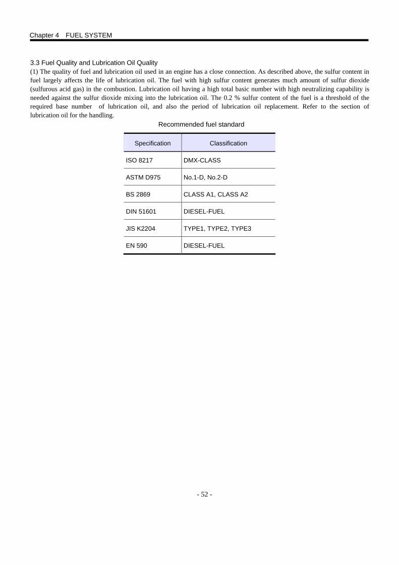
- 52 -
3.3 Fuel Quality and Lubrication Oil Quality (1) The quality of fuel and lubrication oil used in an engine has a close connection. As described above, the sulfur content in fuel largely affects the life of lubrication oil. The fuel with high sulfur content generates much amount of sulfur dioxide (sulfurous acid gas) in the combustion. Lubrication oil having a high total basic number with high neutralizing capability is needed against the sulfur dioxide mixing into the lubrication oil. The 0.2 % sulfur content of the fuel is a threshold of the required base number of lubrication oil, and also the period of lubrication oil replacement. Refer to the section of lubrication oil for the handling.
Recommended fuel standard
Specification Classification
ISO 8217 DMX-CLASS
ASTM D975 No.1-D, No.2-D
BS 2869 CLASS A1, CLASS A2
DIN 51601 DIESEL-FUEL
JIS K2204 TYPE1, TYPE2, TYPE3
EN 590 DIESEL-FUEL
Chapter 4 FUEL SYSTEM
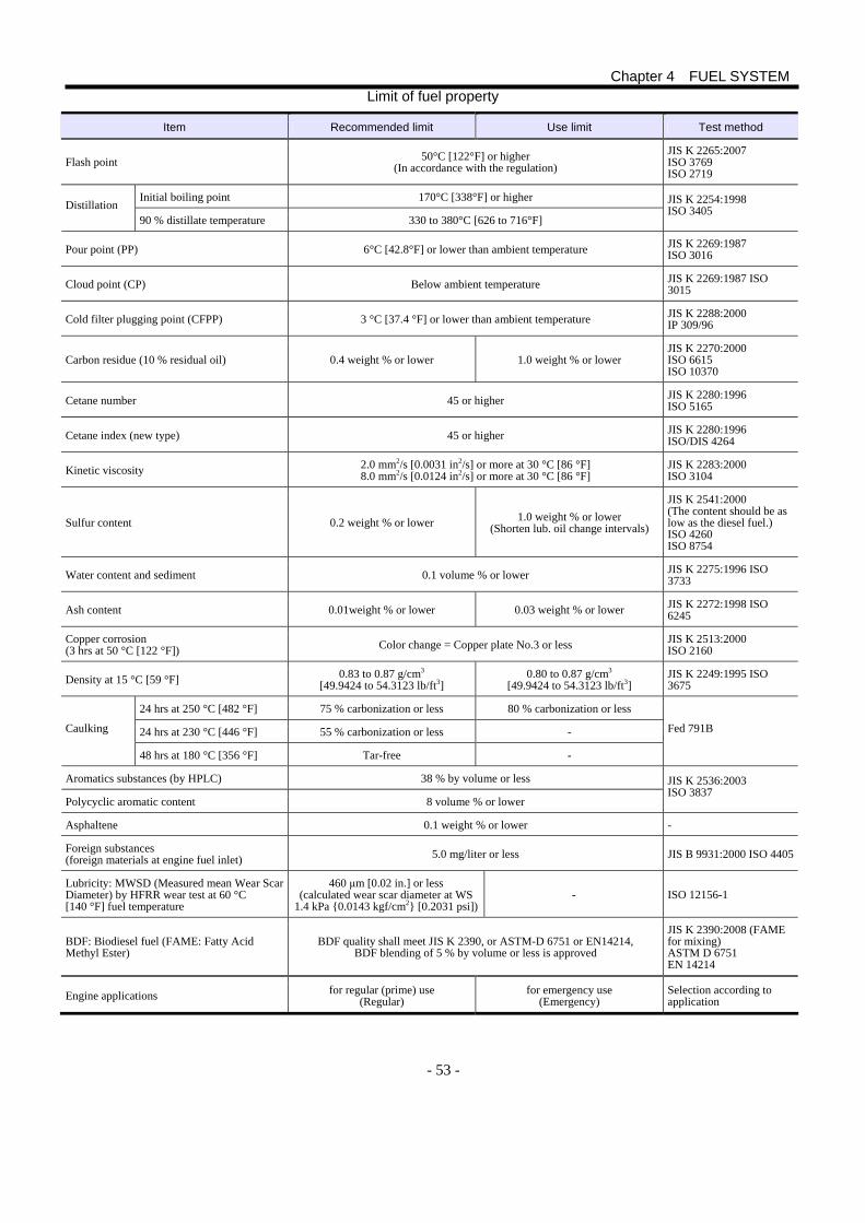
- 53 -
Limit of fuel property
Item Recommended limit Use limit Test method
Flash point 50°C [122°F] or higher (In accordance with the regulation)
JIS K 2265:2007 ISO 3769 ISO 2719
Initial boiling point 170°C [338°F] or higher Distillation
90 % distillate temperature 330 to 380°C [626 to 716°F]
JIS K 2254:1998 ISO 3405
Pour point (PP) 6°C [42.8°F] or lower than ambient temperature JIS K 2269:1987 ISO 3016
Cloud point (CP) Below ambient temperature JIS K 2269:1987 ISO 3015
Cold filter plugging point (CFPP) 3 °C [37.4 °F] or lower than ambient temperature JIS K 2288:2000 IP 309/96
Carbon residue (10 % residual oil) 0.4 weight % or lower 1.0 weight % or lower JIS K 2270:2000 ISO 6615 ISO 10370
Cetane number 45 or higher JIS K 2280:1996 ISO 5165
Cetane index (new type) 45 or higher JIS K 2280:1996 ISO/DIS 4264
Kinetic viscosity 2.0 mm2/s [0.0031 in2/s] or more at 30 °C [86 °F] 8.0 mm2/s [0.0124 in2/s] or more at 30 °C [86 °F]
JIS K 2283:2000 ISO 3104
Sulfur content 0.2 weight % or lower 1.0 weight % or lower (Shorten lub. oil change intervals)
JIS K 2541:2000 (The content should be as low as the diesel fuel.) ISO 4260 ISO 8754
Water content and sediment 0.1 volume % or lower JIS K 2275:1996 ISO 3733
Ash content 0.01weight % or lower 0.03 weight % or lower JIS K 2272:1998 ISO 6245
Copper corrosion (3 hrs at 50 °C [122 °F]) Color change = Copper plate No.3 or less JIS K 2513:2000
ISO 2160
Density at 15 °C [59 °F] 0.83 to 0.87 g/cm3 [49.9424 to 54.3123 lb/ft3]
0.80 to 0.87 g/cm3 [49.9424 to 54.3123 lb/ft3]
JIS K 2249:1995 ISO 3675
24 hrs at 250 °C [482 °F] 75 % carbonization or less 80 % carbonization or less
24 hrs at 230 °C [446 °F] 55 % carbonization or less - Caulking
48 hrs at 180 °C [356 °F] Tar-free -
Fed 791B
Aromatics substances (by HPLC) 38 % by volume or less
Polycyclic aromatic content 8 volume % or lower
JIS K 2536:2003 ISO 3837
Asphaltene 0.1 weight % or lower -
Foreign substances (foreign materials at engine fuel inlet) 5.0 mg/liter or less JIS B 9931:2000 ISO 4405
Lubricity: MWSD (Measured mean Wear Scar Diameter) by HFRR wear test at 60 °C [140 °F] fuel temperature
460 μm [0.02 in.] or less (calculated wear scar diameter at WS
1.4 kPa {0.0143 kgf/cm2} [0.2031 psi])- ISO 12156-1
BDF: Biodiesel fuel (FAME: Fatty Acid Methyl Ester)
BDF quality shall meet JIS K 2390, or ASTM-D 6751 or EN14214, BDF blending of 5 % by volume or less is approved
JIS K 2390:2008 (FAME for mixing) ASTM D 6751 EN 14214
Engine applications for regular (prime) use (Regular)
for emergency use (Emergency)
Selection according to application
Chapter 4 FUEL SYSTEM
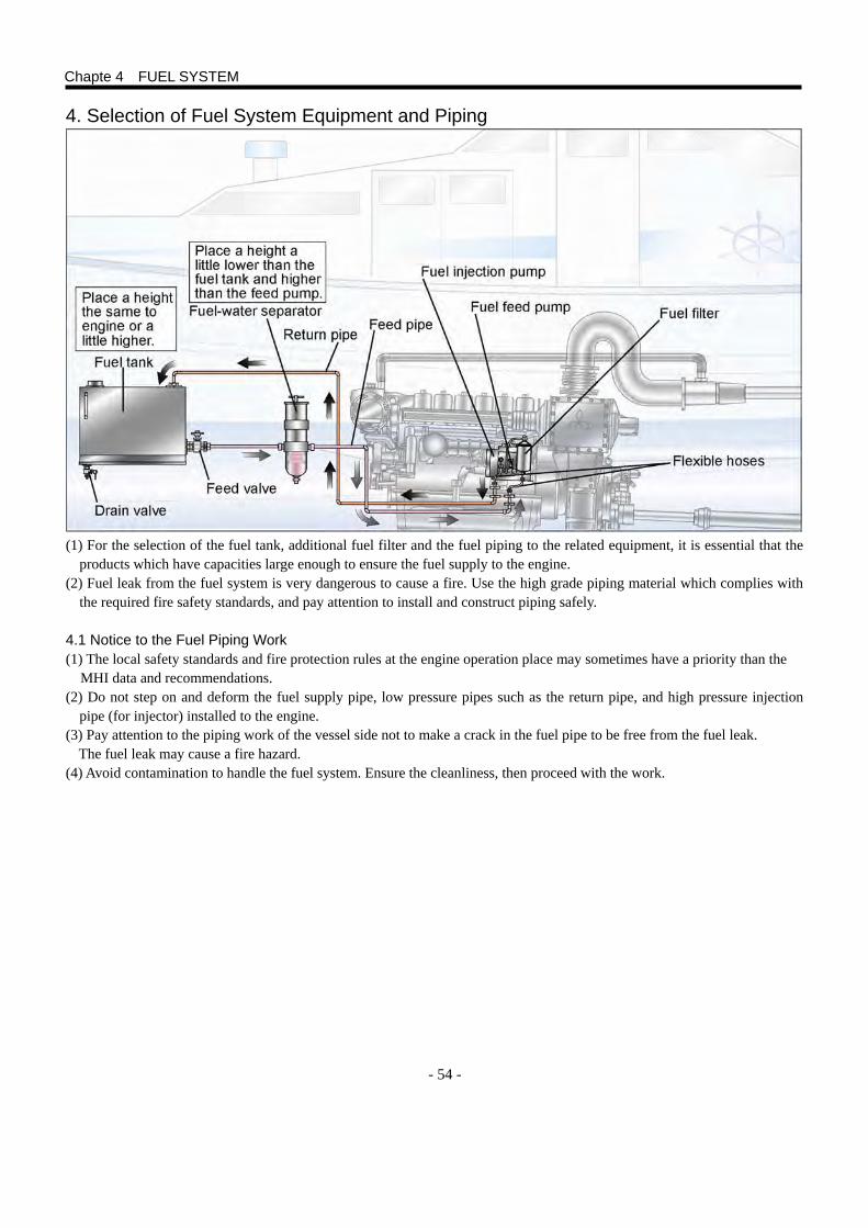
- 54 -
4. Selection of Fuel System Equipment and Piping
(1) For the selection of the fuel tank, additional fuel filter and the fuel piping to the related equipment, it is essential that the products which have capacities large enough to ensure the fuel supply to the engine.
(2) Fuel leak from the fuel system is very dangerous to cause a fire. Use the high grade piping material which complies with the required fire safety standards, and pay attention to install and construct piping safely.
4.1 Notice to the Fuel Piping Work (1) The local safety standards and fire protection rules at the engine operation place may sometimes have a priority than the MHI data and recommendations. (2) Do not step on and deform the fuel supply pipe, low pressure pipes such as the return pipe, and high pressure injection
pipe (for injector) installed to the engine. (3) Pay attention to the piping work of the vessel side not to make a crack in the fuel pipe to be free from the fuel leak.
The fuel leak may cause a fire hazard. (4) Avoid contamination to handle the fuel system. Ensure the cleanliness, then proceed with the work.
Chapte 4 FUEL SYSTEM
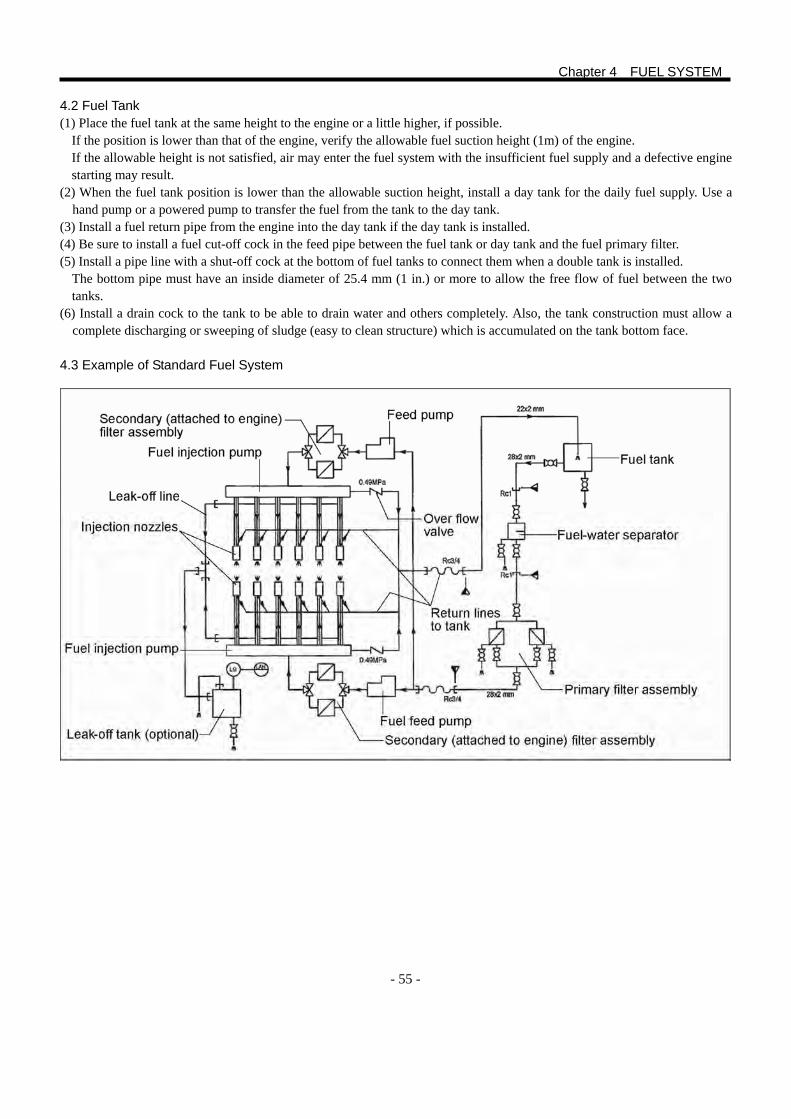
- 55 -
4.2 Fuel Tank (1) Place the fuel tank at the same height to the engine or a little higher, if possible.
If the position is lower than that of the engine, verify the allowable fuel suction height (1m) of the engine. If the allowable height is not satisfied, air may enter the fuel system with the insufficient fuel supply and a defective engine starting may result.
(2) When the fuel tank position is lower than the allowable suction height, install a day tank for the daily fuel supply. Use a hand pump or a powered pump to transfer the fuel from the tank to the day tank.
(3) Install a fuel return pipe from the engine into the day tank if the day tank is installed. (4) Be sure to install a fuel cut-off cock in the feed pipe between the fuel tank or day tank and the fuel primary filter. (5) Install a pipe line with a shut-off cock at the bottom of fuel tanks to connect them when a double tank is installed.
The bottom pipe must have an inside diameter of 25.4 mm (1 in.) or more to allow the free flow of fuel between the two tanks.
(6) Install a drain cock to the tank to be able to drain water and others completely. Also, the tank construction must allow a complete discharging or sweeping of sludge (easy to clean structure) which is accumulated on the tank bottom face.
4.3 Example of Standard Fuel System
Chapter 4 FUEL SYSTEM
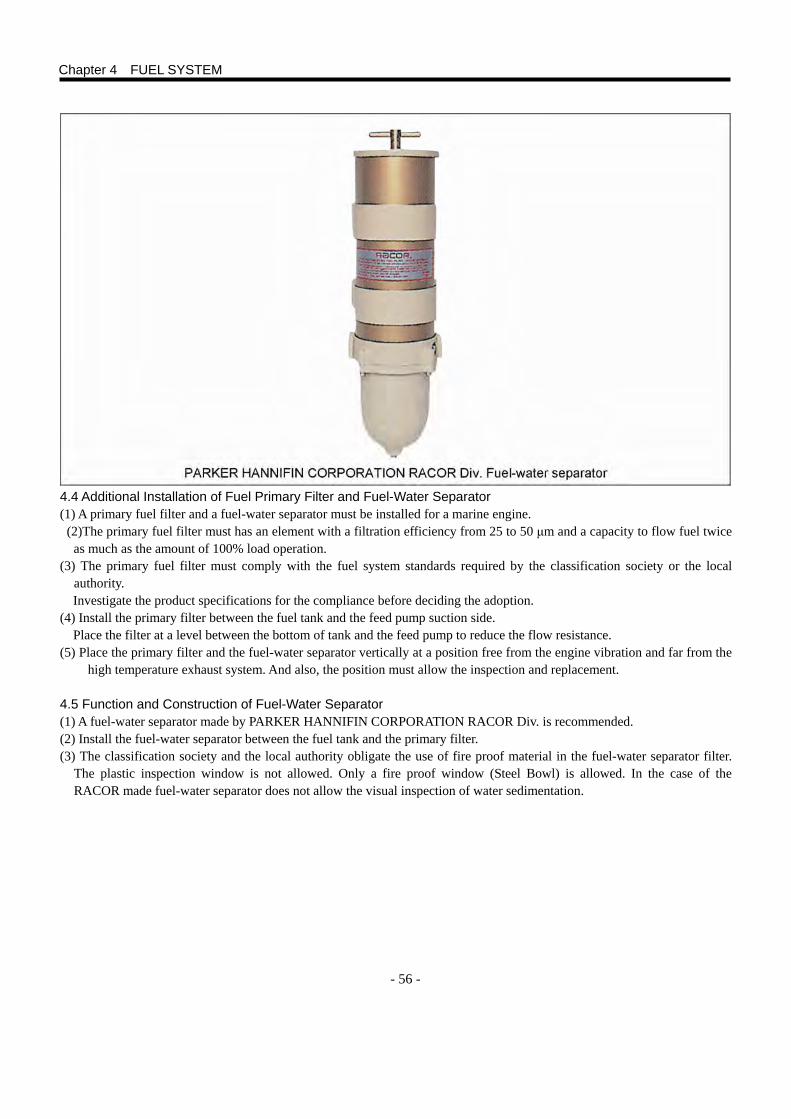
- 56 -
4.4 Additional Installation of Fuel Primary Filter and Fuel-Water Separator (1) A primary fuel filter and a fuel-water separator must be installed for a marine engine. (2)The primary fuel filter must has an element with a filtration efficiency from 25 to 50 μm and a capacity to flow fuel twice
as much as the amount of 100% load operation. (3) The primary fuel filter must comply with the fuel system standards required by the classification society or the local
authority. Investigate the product specifications for the compliance before deciding the adoption.
(4) Install the primary filter between the fuel tank and the feed pump suction side. Place the filter at a level between the bottom of tank and the feed pump to reduce the flow resistance.
(5) Place the primary filter and the fuel-water separator vertically at a position free from the engine vibration and far from the high temperature exhaust system. And also, the position must allow the inspection and replacement.
4.5 Function and Construction of Fuel-Water Separator (1) A fuel-water separator made by PARKER HANNIFIN CORPORATION RACOR Div. is recommended. (2) Install the fuel-water separator between the fuel tank and the primary filter. (3) The classification society and the local authority obligate the use of fire proof material in the fuel-water separator filter.
The plastic inspection window is not allowed. Only a fire proof window (Steel Bowl) is allowed. In the case of the RACOR made fuel-water separator does not allow the visual inspection of water sedimentation.
Chapter 4 FUEL SYSTEM
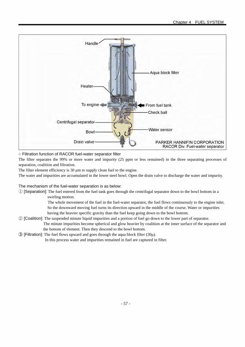
- 57 -
○ Filtration function of RACOR fuel-water separator filter The filter separates the 99% or more water and impurity (25 ppm or less remained) in the three separating processes of separation, coalition and filtration. The filter element efficiency is 30 μm to supply clean fuel to the engine. The water and impurities are accumulated in the lower steel bowl. Open the drain valve to discharge the water and impurity.
The mechanism of the fuel-water separation is as below: ① [Separation]: The fuel entered from the fuel tank goes through the centrifugal separator down to the bowl bottom in a swirling motion.
The whole movement of the fuel in the fuel-water separator, the fuel flows continuously to the engine inlet. So the downward moving fuel turns its direction upward in the middle of the course. Water or impurities having the heavier specific gravity than the fuel keep going down to the bowl bottom.
② [Coalition]: The suspended minute liquid impurities and a portion of fuel go down to the lower part of separator. The minute impurities become spherical and glow heavier by coalition at the inner surface of the separator and the bottom of element. Then they descend to the bowl bottom.
③ [Filtration]: The fuel flows upward and goes through the aqua block filter (30μ). In this process water and impurities remained in fuel are captured in filter.
Chapter 4 FUEL SYSTEM
- 58 -
5. Lubrication Oil Dilution The viscosity of the fuel is 1/40 of that of the lubrication oil. When the fuel is mixed with the lubrication oil, the viscosity of lubrication oil is decreased. With the decrease of lubrication oil viscosity, the oil film formation on each sliding face in engine becomes defective. Such sliding faces on piston rings and bearings are subjected to the defective lubrication. Pay attention to the dilution, which causes the abnormal wear and seizure, and may result in a serious accident. The causes of the mixing of fuel in lubrication oil are thought to be as follows:
5.1 Dilution Caused by the Fuel Leak from Plunger in Fuel Pump (1) During the engine operation, the clearance between plunger and barrel is sealed with fuel film, and the whole amount of
compressed fuel is discharged from the plunger to the injection nozzle. However, when the fuel temperature is excessively high, or a low viscosity fuel is used, the fuel film becomes extremely thin. The fuel leaks through the clearance between the plunger and barrel, and drips down to the cam chamber of fuel pump. Then the fuel goes down to the oil pan, and dilutes the lubrication oil. In a cold district, when the low cetane number fuel oil A mixed with a light oil to lower the pour point, as described before, is used for a prolonged time of low-idling,, the fuel leak amount tends to be significant.
(2) Pay attention to the height of fuel tank when planning its installation. The maximum head drop from the fuel plane to the fuel pump and the negative head drop are specified for MHI engines. If the fuel tank is installed at a position higher than the specification, a static pressure is applied to the plunger chamber by the head drop from the fuel plane. When the engine is left un-operated, the fuel may leak through the clearance between the plunger and barrel with the elapse of the time, drip down to the cam chamber of fuel pump and dilute the lubrication oil.
5.2 Dilution Caused by Defective Combustion or Faulty Spray from Injection Nozzle (1) In a cold district, the cooling water temperature in the water jacket around the cylinder line is low. In this condition, if a
low cetane number fuel is used, the dilution may occur when a prolonged time no-load low-idling operation is made. The un-burnt fuel moves down to the lubrication oil as the fuel can not burnt completely.
(2) In case of the use of low quality crud fuel containing much carbon residue, the hard combustion product accumulates around the nozzle orifice, and the fuel spray is disturbed. This may results in the production of un-burnt fuel caused by the degraded combustion. Also, a foreign substance may be caught at the needle seat of nozzle tip and cause a defective sealing. This also results in the lubrication oil dilution by the un-burnt fuel with the incomplete combustion resulted from the spray failure. A portion of the un-burnt fuel is discharged through the exhaust port. The remaining un-burnt fuel goes through the clearance on the cylinder and gets mixed with the lubrication oil in the oil pan. This phenomenon is often seen in the light load operations.
Chapter 4 FUEL SYSTEM
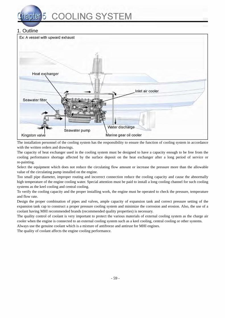
- 59 -
1. Outline
The installation personnel of the cooling system has the responsibility to ensure the function of cooling system in accordance with the written orders and drawings. The capacity of heat exchanger used in the cooling system must be designed to have a capacity enough to be free from the cooling performance shortage affected by the surface deposit on the heat exchanger after a long period of service or re-painting. Select the equipment which does not reduce the circulating flow amount or increase the pressure more than the allowable value of the circulating pump installed on the engine. Too small pipe diameter, improper routing and incorrect connection reduce the cooling capacity and cause the abnormally high temperature of the engine cooling water. Special attention must be paid to install a long cooling channel for such cooling systems as the keel cooling and central cooling. To verify the cooling capacity and the proper installing work, the engine must be operated to check the pressure, temperature and flow rate. Design the proper combination of pipes and valves, ample capacity of expansion tank and correct pressure setting of the expansion tank cap to construct a proper pressure cooling system and minimize the corrosion and erosion. Also, the use of a coolant having MHI recommended brands (recommended quality properties) is necessary. The quality control of coolant is very important to protect the various materials of external cooling system as the charge air cooler when the engine is connected to an external cooling system such as a keel cooling, central cooling or other systems. Always use the genuine coolant which is a mixture of antifreeze and antirust for MHI engines. The quality of coolant affects the engine cooling performance.
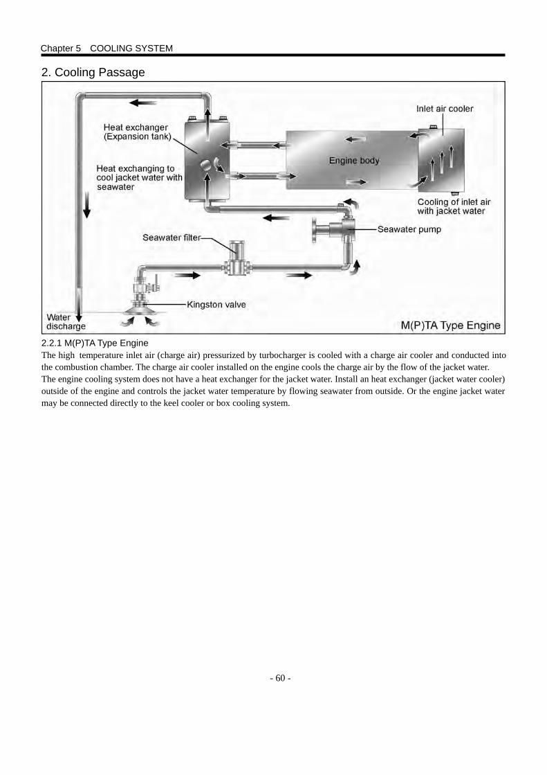
- 60 -
2. Cooling Passage
2.2.1 M(P)TA Type Engine The high temperature inlet air (charge air) pressurized by turbocharger is cooled with a charge air cooler and conducted into the combustion chamber. The charge air cooler installed on the engine cools the charge air by the flow of the jacket water. The engine cooling system does not have a heat exchanger for the jacket water. Install an heat exchanger (jacket water cooler) outside of the engine and controls the jacket water temperature by flowing seawater from outside. Or the engine jacket water may be connected directly to the keel cooler or box cooling system.
Chapter 5 COOLING SYSTEM
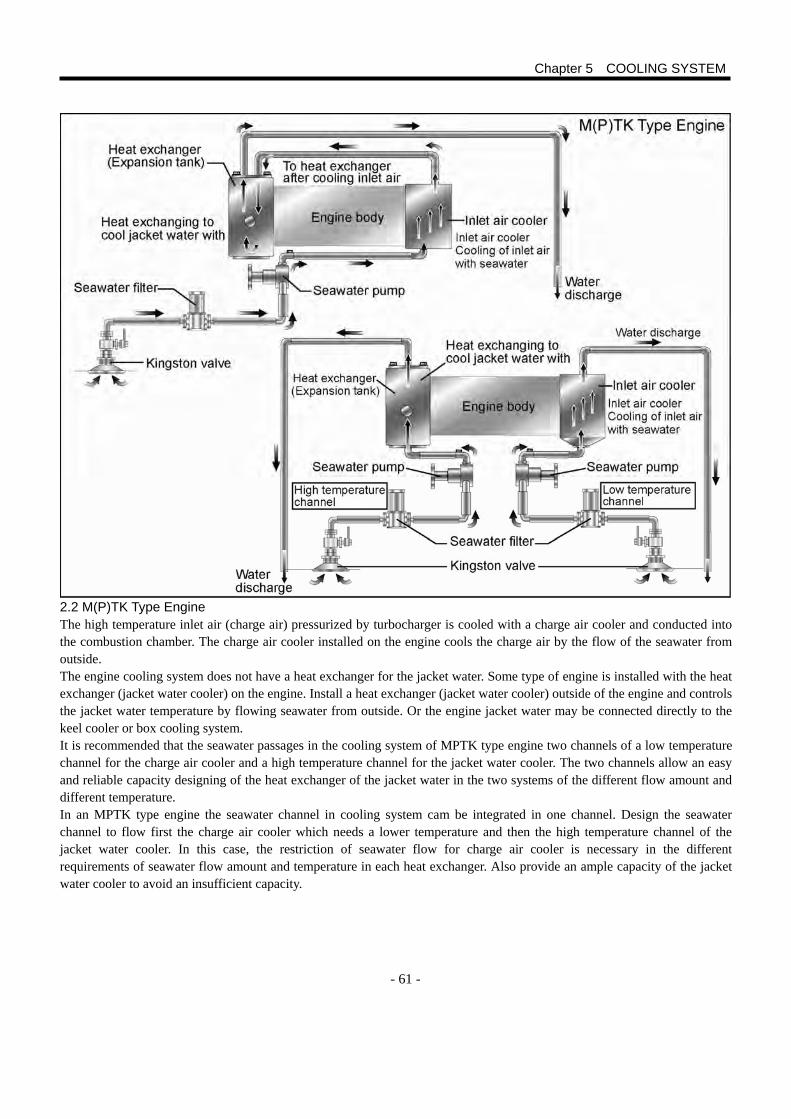
- 61 -
2.2 M(P)TK Type Engine The high temperature inlet air (charge air) pressurized by turbocharger is cooled with a charge air cooler and conducted into the combustion chamber. The charge air cooler installed on the engine cools the charge air by the flow of the seawater from outside. The engine cooling system does not have a heat exchanger for the jacket water. Some type of engine is installed with the heat exchanger (jacket water cooler) on the engine. Install a heat exchanger (jacket water cooler) outside of the engine and controls the jacket water temperature by flowing seawater from outside. Or the engine jacket water may be connected directly to the keel cooler or box cooling system. It is recommended that the seawater passages in the cooling system of MPTK type engine two channels of a low temperature channel for the charge air cooler and a high temperature channel for the jacket water cooler. The two channels allow an easy and reliable capacity designing of the heat exchanger of the jacket water in the two systems of the different flow amount and different temperature. In an MPTK type engine the seawater channel in cooling system cam be integrated in one channel. Design the seawater channel to flow first the charge air cooler which needs a lower temperature and then the high temperature channel of the jacket water cooler. In this case, the restriction of seawater flow for charge air cooler is necessary in the different requirements of seawater flow amount and temperature in each heat exchanger. Also provide an ample capacity of the jacket water cooler to avoid an insufficient capacity.
Chapter 5 COOLING SYSTEM
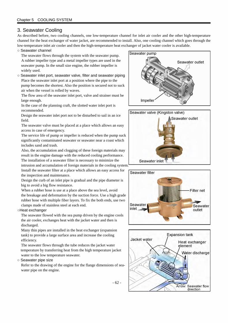
- 62 -
3. Seawater Cooling As described before, two cooling channels, one low-temperature channel for inlet air cooler and the other high-temperature channel for the heat exchanger of water jacket, are recommended to install. Also, one cooling channel which goes through the low-temperature inlet air cooler and then the high-temperature heat exchanger of jacket water cooler is available. ○ Seawater channel The seawater flows through the system with the seawater pump.
A rubber impeller type and a metal impeller types are used in the seawater pump. In the small size engine, the rubber impeller is widely used.
○ Seawater inlet port, seawater valve, filter and seawater piping Place the seawater inlet port at a position where the pipe to the pump becomes the shortest. Also the position is secured not to suck air when the vessel is rolled by waves. The flow area of the seawater inlet port, valve and strainer must be large enough. In the case of the planning craft, the slotted water inlet port is recommended.
Design the seawater inlet port not to be disturbed to sail in an ice field. The seawater valve must be placed at a place which allows an easy access in case of emergency. The service life of pump or impeller is reduced when the pump suck significantly contaminated seawater or seawater near a coast which includes sand and trash. Also, the accumulation and clogging of these foreign materials may result in the engine damage with the reduced cooling performance.
The installation of a seawater filter is necessary to minimize the intrusion and accumulation of foreign materials in the cooling system. Install the seawater filter at a place which allows an easy access for the inspection and maintenance. Design the curb of an inlet pipe is gradual and the pipe diameter is big to avoid a big flow resistance. When a rubber hose is use at a place above the sea level, avoid the breakage and deformation by the suction force. Use a high grade rubber hose with multiple fiber layers. To fix the both ends, use two clamps made of stainless steel at each end.
○Heat exchanger The seawater flowed with the sea pump driven by the engine cools
the air cooler, exchanges heat with the jacket water and then is discharged.
Many thin pipes are installed in the heat exchanger (expansion tank) to provide a large surface area and increase the cooling efficiency.
The seawater flows through the tube reduces the jacket water temperature by transferring heat from the high temperature jacket water to the low temperature seawater.
○ Seawater pipe size Refer to the drawing of the engine for the flange dimensions of sea- water pipe on the engine.
Chapter 5 COOLING SYSTEM
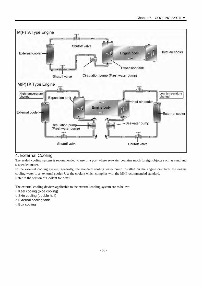
- 63 -
4. External Cooling The sealed cooling system is recommended to use in a port where seawater contains much foreign objects such as sand and suspended mater. In the external cooling system, generally, the standard cooling water pump installed on the engine circulates the engine cooling water to an external cooler. Use the coolant which complies with the MHI recommended standard. Refer to the section of Coolant for detail.
The external cooling devices applicable to the external cooling system are as below: ○ Keel cooling (pipe cooling) ○ Skin cooling (double hull) ○ External cooling tank ○ Box cooling
Chapter 5 COOLING SYSTEM

- 64 -
○ Keel cooling (pipe cooling) The jacket water, generally, is circulated in the cooling pipes of the
keel cooler with the cooling water pump installed on the engine. The cooling pipes are installed outside the hull bottom and the
pipes contact with much amount of seawater. As a result, the heat transfer efficiency is high.
○ Skin cooling (double hull) The jacket water is circulated in the cooling area of the keel cooler
as the keel cooling system with the cooling water pump installed on the engine. The circulating passages are designed to be separated with plates and to flow the coolant smoothly.
In either case, the maximum temperature of the water jacket is defined by the size of the keel cooler.
In other words, the heat transfer efficiency depends mainly on the cooling water temperature, heat transfer area and others.
Chapter5 COOLING SYSTEM
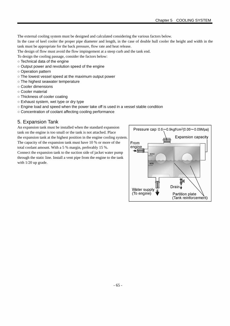
- 65 -
The external cooling system must be designed and calculated considering the various factors below. In the case of keel cooler the proper pipe diameter and length, in the case of double hull cooler the height and width in the tank must be appropriate for the back pressure, flow rate and heat release. The design of flow must avoid the flow impingement at a steep curb and the tank end. To design the cooling passage, consider the factors below: ○ Technical data of the engine ○ Output power and revolution speed of the engine ○ Operation pattern ○ The lowest vessel speed at the maximum output power ○ The highest seawater temperature ○ Cooler dimensions ○ Cooler material ○ Thickness of cooler coating ○ Exhaust system, wet type or dry type ○ Engine load and speed when the power take off is used in a vessel stable condition ○ Concentration of coolant affecting cooling performance
5. Expansion Tank An expansion tank must be installed when the standard expansion tank on the engine is too small or the tank is not attached. Place the expansion tank at the highest position in the engine cooling system. The capacity of the expansion tank must have 10 % or more of the total coolant amount. With a 5 % margin, preferably 15 %. Connect the expansion tank to the suction side of jacket water pump through the static line. Install a vent pipe from the engine to the tank with 1/20 up grade.
Chapter 5 COOLING SYSTEM
- 66 -
6. Mitsubishi genuine long life coolant (GLASSY and PG GLASSY) is recommended to
use in the MHI diesel engine. [Hereinafter the Mitsubishi genuine long life coolant (GLASSY and PG GLASSY) is referred to as the genuine LLC.] (1) A low-price cheap coolant will consume its antirust additive and lower the durability and rust protection when it is used in
the MHI engine used in a severe condition. As a result, replacement of parts and much amount of maintenance cost for heat exchanger clogging, water leak, charge air cooler rust, cylinder liner cavitation erosion and others will be the result.
(2) The genuine LLC is a coolant developed exclusively for the MHI engines. It prevents the cooling system from part corrosion and cavitation erosion and coolant from freezing.
(3) The genuine LLC consists of special antirust/anti-corrosion additives and ethylene glycol or propylene glycol. The ethylene glycol increases viscosity and prevents the cylinder line from cavitation erosion. Moreover, it forms a corrosion protective film to protect the film from peeling caused by the repeating cylinder liner impacts and resist the acceleration of cavitation erosion. (The corrosion of surface film accelerates the peeling by impact pressure. The LLC is effective to protect the film.)
(4) The genuine LLC contains long-life organic acid salts and mineral antirust/anti-corrosion additives without containing various troublesome antirust/anti-corrosion additives such as amine, nitrite salt, borate salt and silicate. It keeps strong antirust/anti-corrosion effects during a prolonged period of time under a severe load condition. The additives are hear and acid resistant and prevent the cooling system from leaking and clogging caused by corrosion.
(5) GLASSY is toxic as the base contains ethylene glycol. The discharge of the waste coolant to river is prohibited. However it does not form the carcinogenic nitrosamine as it does not contain nitrite salt.
(6) PG GLASSY affects very slightly on the human body, and is applicable to the engine used in food industry equipment. It can be called as an environment-friendly coolant as it does not contains toxic chemicals.
7. Required Performance of Coolant Used for Engine Jacket Water. (1) Coolant must be a mixture of water, antirust agent and antifreeze solution. (2) Water, antirust agent and antifreeze solution must have qualities comply with MHI standards. (3) The coolant is required to have functions below. ○ Proper heat exchange capability and amount ○ Sufficient anti-rust function for cast iron, copper, copper alloy, aluminum and solder. ○ Sufficient anti-erosion function against cavitation ○ Margins to the freezing and boiling temperatures ○ Free from sludge and scale deposit ○ Having no-attacking effect to non-metal materials such as rubber hose and water seal 8. Required Performance and Quality of Water Used in Coolant (1) Rust will always be produced after a high temperature condition of cooling water if only water is used as a coolant.
Coolant containing only water can not be permitted. (2) Distilled water or ion-exchange water can be used to make a coolant, however do not use the distilled water or
ion-exchanged water only to be used as a coolant. The metal corrosion of cupper metal in the cooling system will be accelerated. Be sure to mix the antirust agent and antifreeze solution.
(3)Use the water for coolant which satisfies the standards in the table below. Never use such hard water as river water because it will cause rust and radiator clogging. In Japan, use tap water to make the mixture.
Chapter 5 COOLING SYSTEM
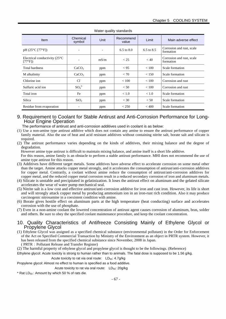
- 67 -
Water quality standards
Item Chemical symbol Unit Recommend
value Limit Main adverse effect
pH (25°C [77°F]) - - 6.5 to 8.0 6.5 to 8.5 Corrosion and rust, scale formation
Electrical conductivity (25°C [77°F]) - mS/m < 25 < 40 Corrosion and rust, scale
formation
Total hardness CaCO3 ppm < 95 < 100 Scale formation
M alkalinity CaCO3 ppm < 70 < 150 Scale formation
Chlorine ion Cl- ppm < 100 < 100 Corrosion and rust
Sulfuric acid ion SO42- ppm < 50 < 100 Corrosion and rust
Total iron Fe ppm < 1.0 < 1.0 Scale formation
Silica SiO2 ppm < 30 < 50 Scale formation
Residue from evaporation - ppm < 250 < 400 Scale formation
9. Requirement to Coolant for Stable Antirust and Anti-Corrosion Performance for Long-
Hour Engine Operation The performance of antirust and anti-corrosion additives used in coolant is as below:
(1) Use a non-amine type antirust additive which does not contain any amine to ensure the antirust performance of copper family material. Also the use of heat and acid resistant additives without containing nitrite salt, borate salt and silicate is required.
(2) The antirust performance varies depending on the kinds of additives, their mixing balance and the degree of degradation.
However amine type antirust is difficult to maintain mixing balance, and amine itself is a short life additive. For this reason, amine family is an obstacle to perform a stable antirust performance. MHI does not recommend the use of amine type antirust for this reason.
(3) Additives have different target metals. Some additives have adverse effect to accelerate corrosion on some metal other than the target. Amine attacks copper metal strongly, and it accelerates the consumption of antirust/anti-corrosion additives for copper metal. Contrarily, a coolant without amine reduce the consumption of antirust/anti-corrosion additives for copper metal, and the reduced copper metal corrosion result in a reduced secondary corrosion of iron and aluminum metals.
(4) Silicate is unstable and precipitated in gelatinization. It loses the antirust effect on aluminum and the gelated silicate accelerates the wear of water pump mechanical seal.
(5) Nitrite salt is a low cost and effective antirust/anti-corrosion additive for iron and cast iron. However, its life is short and will strongly attack copper metal by producing ammonium ion in an iron-rust rich condition. Also it may produce carcinogenic nitrosamine in a coexistent condition with amine.
(6) Borate gives hostile effect on aluminum parts at the high temperature (heat conducting) surface and accelerates corrosion with the use of phosphate.
(7) Even in a non-amine coolant the lowered concentration of antirust agent causes corrosion of aluminum, bras, solder and others. Be sure to obey the specified coolant maintenance procedure, and keep the coolant concentration.
10. Quality Characteristics of Antifreeze Consisting Mainly of Ethylene Glycol or
Propylene Glycol (1) Ethylene Glycol was assigned as a specified chemical substance (environmental pollutant) in the Order for Enforcement
of the Act on Specified Commercial Transaction by Ministry of the Environment as an object in PRTR system. However, it has been released from the specified chemical substance since November, 2008 in Japan. ( PRTR:Pollutant Release and Transfer Register)
(2) The harmful property of ethylene glycol and propylene glycol is thought to be the followings. (Reference) Ethylene glycol: Acute toxicity is strong to human rather than to animals. The fatal dose is supposed to be 1.56 g/kg. Acute toxicity to rat via oral route: LD50: 4.7g/kg Propylene glycol: Almost no effect to human is specified as a food additive.
Acute toxicity to rat via oral route: LD50: 20g/kg * Rat LD50 : Amount by which 50 % of rats die.
Chapter 5 COOLING SYSTEM
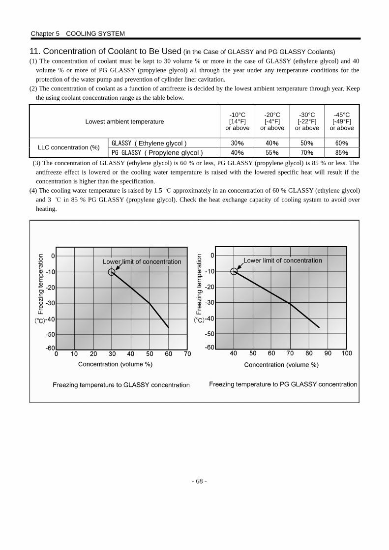
- 68 -
11. Concentration of Coolant to Be Used (in the Case of GLASSY and PG GLASSY Coolants) (1) The concentration of coolant must be kept to 30 volume % or more in the case of GLASSY (ethylene glycol) and 40
volume % or more of PG GLASSY (propylene glycol) all through the year under any temperature conditions for the protection of the water pump and prevention of cylinder liner cavitation.
(2) The concentration of coolant as a function of antifreeze is decided by the lowest ambient temperature through year. Keep the using coolant concentration range as the table below.
(3) The concentration of GLASSY (ethylene glycol) is 60 % or less, PG GLASSY (propylene glycol) is 85 % or less. The antifreeze effect is lowered or the cooling water temperature is raised with the lowered specific heat will result if the concentration is higher than the specification.
(4) The cooling water temperature is raised by 1.5 ℃ approximately in an concentration of 60 % GLASSY (ethylene glycol) and 3 ℃ in 85 % PG GLASSY (propylene glycol). Check the heat exchange capacity of cooling system to avoid over heating.
Lowest ambient temperature
-10°C [14°F]
or above
-20°C [-4°F]
or above
-30°C [-22°F]
or above
-45°C [-49°F]
or above
GLASSY ( Ethylene glycol ) 30% 40% 50% 60% LLC concentration (%) PG GLASSY ( Propylene glycol ) 40% 55% 70% 85%
Chapter 5 COOLING SYSTEM
- 69 -
12. Precautions to Use MHI Genuine Long Life Coolant: GLASSY and PG GLASSY (1) Pour the genuine LLC after washing thoroughly inside of the cooling system. The consumption of additives is
accelerated and they can not work fully if rust or scale remains in the cooling system. Be sure to repair the leak in the cooling system before using the coolant, if necessary.
(2) Use tap water as dilution water in Japan. (3) Pour in the required amount of genuine LLC first. Then fill with dilution water. Start the engine to circulate fully in the
cooling system. Bleed air thoroughly from the cooling system. (4) Never add water only when the coolant becomes low level. The concentration will be lowered.
Be sure to blend the same concentration of coolant as initially poured GLASSY, and add the blend. (5) Dilute GLASSY in the range of 30 to 60 volume % or PG GLASSY 40 to 85 % and use the cooling water as the coolant.
The concentration of ethylene glycol in GLASSY is 91 weight %. The concentration of propylene glycol is 65 weight %.
(6) Replace the genuine LLC two years after pouring or 8000 service hours, whichever comes first. (7) Do not mix the genuine LLC with other brand antirust, antifreeze or coolant or the performance of the LLC is impaired.
13. Freezing Temperature of Ethylene Glycol and Propylene Glycol The freezing temperature of ethylene glycol and propylene glycol depend on the concentration of mixture. However, the concentration of weight % to the freezing temperature is almost the same when considering the concentration in weight ratio (%). Use a refractometer to maintain the concentration to be 30 to 60 % when a long life coolant other than the genuine one is inevitably used. Refer to the operation manual of the refractometer when you use one.
The environmental temperature is between -10 ℃ to -45 ℃ in this case.
Chapter 5 COOLING SYSTEM
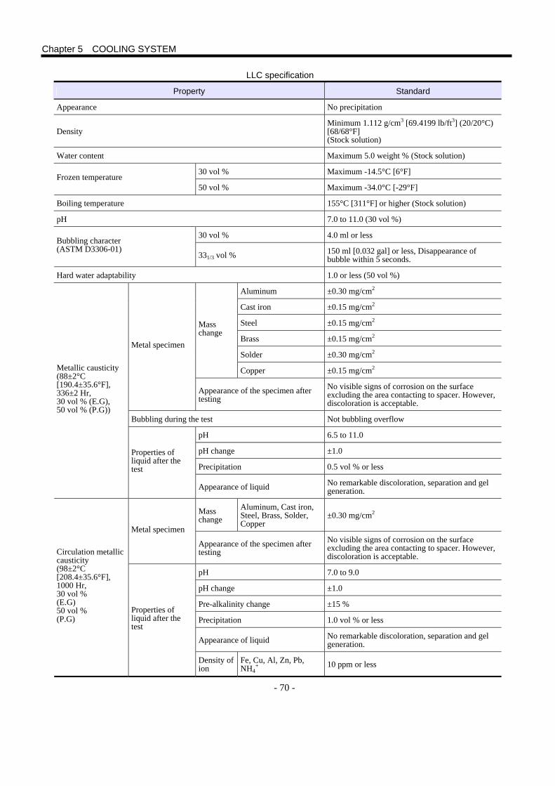
- 70 -
LLC specification
Property Standard
Appearance No precipitation
Density Minimum 1.112 g/cm3 [69.4199 lb/ft3] (20/20°C) [68/68°F] (Stock solution)
Water content Maximum 5.0 weight % (Stock solution)
30 vol % Maximum -14.5°C [6°F] Frozen temperature
50 vol % Maximum -34.0°C [-29°F]
Boiling temperature 155°C [311°F] or higher (Stock solution)
pH 7.0 to 11.0 (30 vol %)
30 vol % 4.0 ml or less Bubbling character (ASTM D3306-01)
331/3 vol % 150 ml [0.032 gal] or less, Disappearance of bubble within 5 seconds.
Hard water adaptability 1.0 or less (50 vol %)
Aluminum ±0.30 mg/cm2
Cast iron ±0.15 mg/cm2
Steel ±0.15 mg/cm2
Brass ±0.15 mg/cm2
Solder ±0.30 mg/cm2
Mass change
Copper ±0.15 mg/cm2
Metal specimen
Appearance of the specimen after testing
No visible signs of corrosion on the surface excluding the area contacting to spacer. However, discoloration is acceptable.
Bubbling during the test Not bubbling overflow
pH 6.5 to 11.0
pH change ±1.0
Precipitation 0.5 vol % or less
Metallic causticity (88±2°C [190.4±35.6°F], 336±2 Hr, 30 vol % (E.G), 50 vol % (P.G))
Properties of liquid after the test
Appearance of liquid No remarkable discoloration, separation and gel generation.
Mass change
Aluminum, Cast iron, Steel, Brass, Solder, Copper
±0.30 mg/cm2
Metal specimen
Appearance of the specimen after testing
No visible signs of corrosion on the surface excluding the area contacting to spacer. However, discoloration is acceptable.
pH 7.0 to 9.0
pH change ±1.0
Pre-alkalinity change ±15 %
Precipitation 1.0 vol % or less
Appearance of liquid No remarkable discoloration, separation and gel generation.
Circulation metallic causticity (98±2°C [208.4±35.6°F], 1000 Hr, 30 vol % (E.G) 50 vol % (P.G)
Properties of liquid after the test
Density of ion
Fe, Cu, Al, Zn, Pb, NH4
+ 10 ppm or less
Chapter 5 COOLING SYSTEM
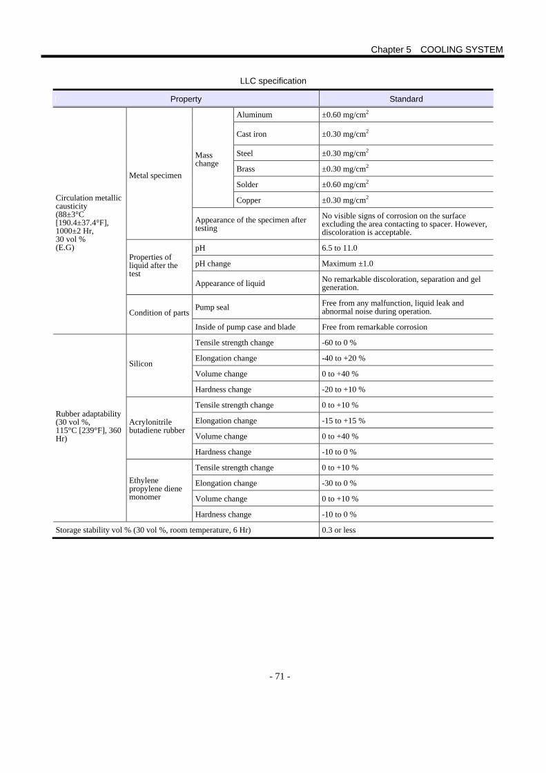
- 71 -
LLC specification
Property Standard
Aluminum ±0.60 mg/cm2
Cast iron ±0.30 mg/cm2
Steel ±0.30 mg/cm2
Brass ±0.30 mg/cm2
Solder ±0.60 mg/cm2
Mass change
Copper ±0.30 mg/cm2
Metal specimen
Appearance of the specimen after testing
No visible signs of corrosion on the surface excluding the area contacting to spacer. However, discoloration is acceptable.
pH 6.5 to 11.0
pH change Maximum ±1.0 Properties of liquid after the test
Appearance of liquid No remarkable discoloration, separation and gel generation.
Pump seal Free from any malfunction, liquid leak and abnormal noise during operation.
Circulation metallic causticity (88±3°C [190.4±37.4°F], 1000±2 Hr, 30 vol % (E.G)
Condition of parts
Inside of pump case and blade Free from remarkable corrosion
Tensile strength change -60 to 0 %
Elongation change -40 to +20 %
Volume change 0 to +40 % Silicon
Hardness change -20 to +10 %
Tensile strength change 0 to +10 %
Elongation change -15 to +15 %
Volume change 0 to +40 %
Acrylonitrile butadiene rubber
Hardness change -10 to 0 %
Tensile strength change 0 to +10 %
Elongation change -30 to 0 %
Volume change 0 to +10 %
Rubber adaptability (30 vol %, 115°C [239°F], 360 Hr)
Ethylene propylene diene monomer
Hardness change -10 to 0 %
Storage stability vol % (30 vol %, room temperature, 6 Hr) 0.3 or less
Chapter 5 COOLING SYSTEM

- 72 -

- 73 -
1. Outline Use MHI genuine lubrication oil. In a case when a lubrication oil other than the genuine one by necessity, check the oil grade and it must conform with the MHI quality standard. Sample the oil for analysis after engine operation to know the oil replacement interval. A defect in relation to lubrication oil will not be guaranteed when the lubrication oil does not satisfy the MHI standard. Engine lubrication oil not only retains oil film on sliding surfaces and gears to suppress wear, but also treats and cleans combustion products to prevent wear, oxidation, and corrosion. And, the lubrication oil, which works as coolant, removes heat from high-temperature portion to keep an appropriate temperature. Thus, the lubrication oil is extremely important for the functions and service life of engine and also it is an expendable part. 2. Property The properties of engine lubrication oil must meet strict conditions because it is exposed to high-temperature combustion gas, oxides of fuel, etc. during engine running. 2.1 Performance Requirement The lubrication oil used to engine must especially have the following capabilities. ○ Excellent cleaning and dispersion capabilities at high temperature to prevent contamination of sludge and soot inside the
engine Oxides such as sulfur compound produced with burning of sulfur contained in fuel are polymerized to form insoluble sludge. And, incomplete combustion of fuel forms soot. Lubrication oil exposed to high-temperature combustion gas changes into sludge, which is deposited at grooves of piston rings and around exhaust valves. The sludge causes piston ring sticking and breakage or defective sliding in exhaust valve. In addition, the exfoliated sludge is sandwiched between the valve and valve seat to cause combustion pressure leak. Dispersing sludge and soot to lubrication oil without depositing them inside the engine maintains the cleanliness of each part.
○ High acid-neutralizing capability in order to suppress oxidation by sulfur contained in fuel Fuel containing much sulfur forms much sulfur dioxide (sulfurous acid gas) when burned. And, the sulfur dioxide is mixed into lubrication oil. Therefore, lubrication oil must have high base number and high acid-neutralizing capability.
○ High-temperature oxidation stability to endure long-hour high temperature operation In cases such as long-hour, high-load continuous running, high-temperature lubrication oil bonds with oxygen easily and deteriorates rapidly. Then, in combination with sludge mixture, lubrication oil viscosity is extremely increased, which causes problems such as scuffing of piston and cylinder liner, and bearing corrosion.
○ Proper viscosity characteristics to keep the lubricity and , the low-temperature startability ○ Antirust capability sufficient to prevent the parts from rusting and corrosion by water
Antirust and anti-corrosion capability is achieved by forming oil films on engine parts and preventing metals from contacting such substances as corrosive components and soot.
○ Good antifoaming capability to prevent the lubrication oil from degradation with air inclusion 2.2 Recommended Viscosity The lubrication oil used in engine must maintain appropriate viscosity, in response to the temperature around installation site. Generally, the engine oil cooler uses cooling water to cool oil. When the output is enough to fully open the thermostat while the engine is running, oil-water temperature difference is between the oil temperature at oil cooler outlet and the cooling water temperature. The oil temperature cooled in the oil cooler is not cooler than the cooling water temperature, and the oil film thickness in bearing becomes thin as the kinetic viscosity becomes low in high load and high environmental temperature. The oil film formed in the clearance at bearing, between piston ring and cylinder liner, and at cam follower is an important component to generate resistance at the engine starting.
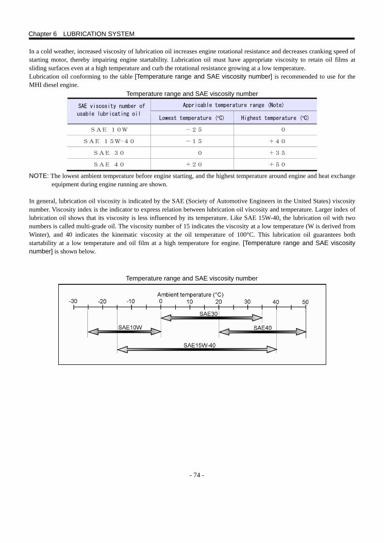
- 74 -
In a cold weather, increased viscosity of lubrication oil increases engine rotational resistance and decreases cranking speed of starting motor, thereby impairing engine startability. Lubrication oil must have appropriate viscosity to retain oil films at sliding surfaces even at a high temperature and curb the rotational resistance growing at a low temperature. Lubrication oil conforming to the table [Temperature range and SAE viscosity number] is recommended to use for the MHI diesel engine.
Temperature range and SAE viscosity number
Appricable temperature range (Note) SAE viscosity number of
usable lubricating oil Lowest temperature (ºC) Highest temperature (ºC)
SAE 10W -25 0
SAE 15W-40 -15 +40
SAE 30 0 +35
SAE 40 +20 +50
NOTE: The lowest ambient temperature before engine starting, and the highest temperature around engine and heat exchange equipment during engine running are shown.
In general, lubrication oil viscosity is indicated by the SAE (Society of Automotive Engineers in the United States) viscosity number. Viscosity index is the indicator to express relation between lubrication oil viscosity and temperature. Larger index of lubrication oil shows that its viscosity is less influenced by its temperature. Like SAE 15W-40, the lubrication oil with two numbers is called multi-grade oil. The viscosity number of 15 indicates the viscosity at a low temperature (W is derived from Winter), and 40 indicates the kinematic viscosity at the oil temperature of 100°C. This lubrication oil guarantees both startability at a low temperature and oil film at a high temperature for engine. [Temperature range and SAE viscosity number] is shown below.
Temperature range and SAE viscosity number
Chapter 6 LUBRICATION SYSTEM

- 75 -
2.3 Additive The lubrication oil used in engine requires various additives to realize the functions described below. The table shows the typical additives and their functions.
Major additives and functions
Additives Type (additive amount) Properties and functions Typical components
Antioxidant Alkylphenol
Organometallic salt
(0.1 to 1.0 %)
s Additive bonds with oxygen to prevent luberication oil from oxidizing
before oil is oxidized.
DBPC Zinc
dialkyl-thiophosphate
Detergent
dispersants
Organometallic salt imide
(Nitrogen type)
(0.5 to 3.0 %)
s Disperses soot or sludge formed withfuel combustion or dust into oil to
prevent them from depositing as solid
matter.
s Neutralizes acid of combustion
products to prevent sludge
formation.
Sulfonate-phenate of Ca,
Ba, Mg
or Ashless dispersant
Viscosity
index
improver
Polymer (0.5 to 1.0 %) s Added mineral oil to prevent
viscosity reduction at high
temperature.
s Defect: When large shear force is applied, polymer is cut into small
pieces to reduce viscosity of
luberication oil.
Polymethylmethacrylate
(PMA)
Polyolefin (OCP)
Pour-point
depressant
Polymer (0.05 to 0.5 %) s Prevents growth of hydrocarbon
crystals to maintain lubricating oil
flowability.
Polymethylmethacrylate
(PMA)
Alkylation aroma compound
Ethylene-vinyl acetate
copolymer
Antifoam Silicon polymer substance
(1.0 to 100 ppm)
s Quickly collapses foam which
promotes oxidation degradation of
lubricating oil.
Silicon oil
Ester oil
Chapter 6 LIBRICATION SYSTEM
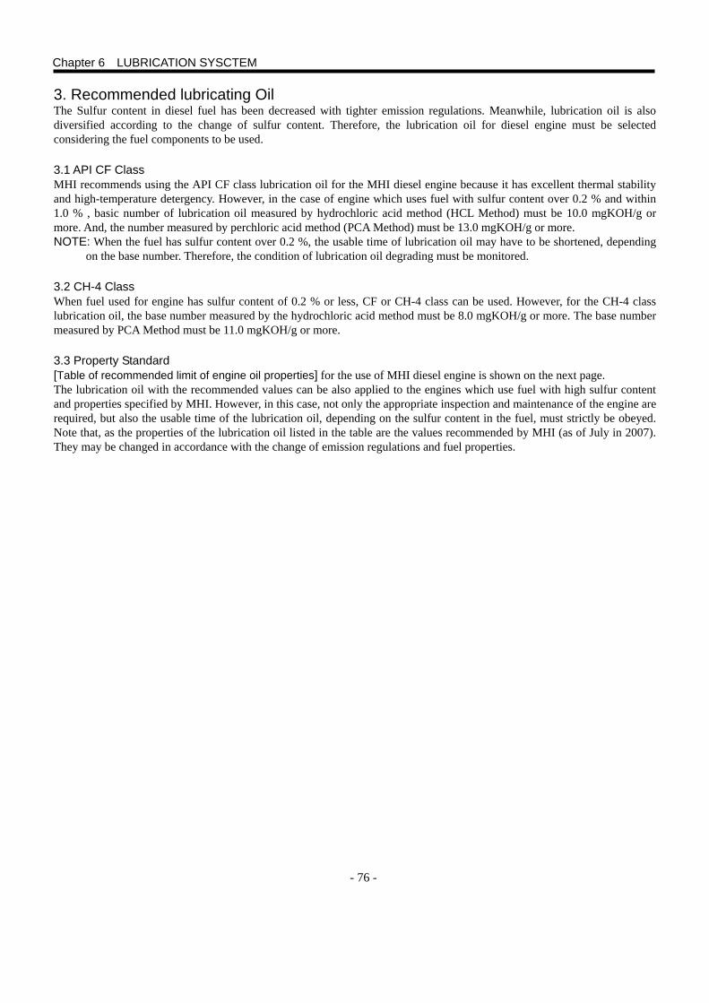
- 76 -
3. Recommended lubricating Oil The Sulfur content in diesel fuel has been decreased with tighter emission regulations. Meanwhile, lubrication oil is also diversified according to the change of sulfur content. Therefore, the lubrication oil for diesel engine must be selected considering the fuel components to be used.
3.1 API CF Class MHI recommends using the API CF class lubrication oil for the MHI diesel engine because it has excellent thermal stability and high-temperature detergency. However, in the case of engine which uses fuel with sulfur content over 0.2 % and within 1.0 % , basic number of lubrication oil measured by hydrochloric acid method (HCL Method) must be 10.0 mgKOH/g or more. And, the number measured by perchloric acid method (PCA Method) must be 13.0 mgKOH/g or more. NOTE: When the fuel has sulfur content over 0.2 %, the usable time of lubrication oil may have to be shortened, depending
on the base number. Therefore, the condition of lubrication oil degrading must be monitored.
3.2 CH-4 Class When fuel used for engine has sulfur content of 0.2 % or less, CF or CH-4 class can be used. However, for the CH-4 class lubrication oil, the base number measured by the hydrochloric acid method must be 8.0 mgKOH/g or more. The base number measured by PCA Method must be 11.0 mgKOH/g or more.
3.3 Property Standard [Table of recommended limit of engine oil properties] for the use of MHI diesel engine is shown on the next page. The lubrication oil with the recommended values can be also applied to the engines which use fuel with high sulfur content and properties specified by MHI. However, in this case, not only the appropriate inspection and maintenance of the engine are required, but also the usable time of the lubrication oil, depending on the sulfur content in the fuel, must strictly be obeyed. Note that, as the properties of the lubrication oil listed in the table are the values recommended by MHI (as of July in 2007). They may be changed in accordance with the change of emission regulations and fuel properties.
Chapter 6 LUBRICATION SYSCTEM
- 77 -
Table of recommended limit of engine oil properties
Item Unit Recommended limit Test method
API/JASO CF class *1 -
SAE viscosity - 15W-40 -
Color ASTM - L4.0 JIS K 2580 ISO 2049
Density 15°C [59°F] g/cm3 0.87 to 0.90
JIS K 2249 ISO 3675 ISO3838
ISO 649-4 ISO 91-1
40°C [104°F] 100 to 110 Kinetic Viscosity:
150°C [302°F] mm2/s
13.5 to 15.5
JIS K 2283 ISO 3107 ISO 2904
Viscosity - - JIS K 2283 ISO 3107 ISO 2904
Flash point °C [°F] 225 to 250 [437 to 482]
JIS K 2265 ISO 3679 ISO 2719 ISO 2592
1.0 weight % or lower 10 or higher (up to 13) Hydrochloric acid
method Sulfur contents of fuel
0.2 weight % or lower
mgKOH/g 8 or higher (up to 13)
1.0 weight % or lower 13 or higher (up to 16)
Base number
Perchloric acid method
Sulfur contents of fuel
0.2 weight % or lower
mgKOH/g 11 or higher (up to 16)
JIS K 2501 ISO 3771 ISO 6618 ISO 6619 ISO 7537
Acid number mgKOH/g 1.5 to 2.0
JIS K 2501 ISO 3771 ISO 6618 ISO 6619 ISO 7537
Sulfur content % 0.5 or less JIS K 2541 ISO 4260 ISO 8754
Sulfuric acid ash % 2.0 or lower JIS K 2272 ISO 3987 ISO 6245
Carbon residue content % 2.0 or lower JIS K 2270 ISO 10370 ISO 6615
High temperature shear viscosity 150°C[302°F] mP·aS 3.7 or higher JPI-5S-36-91
Pour point °C [°F] -25 [-13] or lower JIS K 2269 ISO 3015 ISO 3016
I 10/0
II 30/0 Forming test*2
III
mL
10/0
JIS K 2518 ISO 6247
300°C [572°F] 140 or lower Panel caulking test*3
325°C [617°F]
mg 300 or lower
FED791-3462
*1 It must be certified as API service classification CF by 2009. *2 Temperature of test I (24 °C [75.2 °F]), Temperature of test II (93.5 °C [200. 3°F]), Temperature of test III (24 °C [75.2 °F] after 93.5 °C [200.3 °F]) *3 Temperature of aluminum panel: 300 °C [572 °F] and 325 °C [617 °F] Temperature of engine oil: 100 °C [212 °F], Splatter time: 15 seconds, Downtime: 45 seconds, Test hour: 8 hours, the properties are the weight of solid deposit.
Chapter 6 LUBRICATION SYSTEM
- 78 -
4. Lubrication Oil Deterioration Contamination and deterioration of lubrication oil are not avoidable with the increase of operating hours. High load of engine-driven device and heat exchange equipment and high environmental temperature raise lubrication oil temperature to accelerate deterioration. Especially sulfur content in fuel affects the service life of lubrication oil significantly. 4.1 Factor In addition to the deterioration of lubrication oil itself, mixing with combustion products, oxygen, or foreign objects accelerates further the deterioration and contamination of lubrication oil. 4.1.1 Lubrication Oil The properties of base oil and additives are changed due to oxidation reaction and thermal decomposition or cut polymer molecules in viscosity index improver. In addition, the additive consumption leads to the deterioration of lubrication oil itself. 4.1.2 Contaminant Oxides mixed into the lubrication oil from combustion blow-by and cylinder liners, combustion products such as soot and unburned fuel, and dust that enters from air intake system lead to engine lubrication oil deterioration. Metallic powder caused by wear inside the engine acts as a catalyst of oxidation reaction to accelerate the deterioration together with the moisture contained in combustion blow-by. Sulfur contained in fuel is oxidized to form sulfur dioxide (SO2), which is bonded with moisture by catalyst such as metallic oxide to form the serious contaminant of sulfuric acid (H2SO4). And, nitrogen oxides formed by combustion is also included in the corrosive contaminants. 4.1.3 Oxygen Oxygen that remains unused in the fuel combustion, because excessive air is sucked into the diesel engine combustion chamber, is mixed into combustion blow-by to enter the crankcase. The oxygen that enters the crankcase oxidizes high-temperature lubrication oil. As the high-temperature oxidation degradation progresses, the oil viscosity increases by polymerization of oxides to form the sludge and varnish. The biggest factor in oxidation deterioration is the continuous use of high-temperature lubrication oil due to the long-hour, heavy-load continuous running of the engine. 4.1.4 Fuel Viscosity of fuel is approximately 1/40 of that of lubrication oil. The fuel mixing dilutes the lubrication oil to reduce its viscosity. The materials which dilute lubrication oil are limited, and dilution in engine only indicates the fuel mixture. Dilution factors are as follows: Injection pump
Generally, the injection pump has the plunger reciprocating in barrel to compress fuel to a high pressure. And, a narrow clearance of several microns is made between the plunger and barrel to lubricate them with fuel. When the engine is running, the clearance is sealed by fuel oil film formed with sliding movement of the plunger. Therefore, almost all the compressed fuel is pushed from the plunger into the injection line. However, the fuel oil film becomes extremely thin when the fuel temperature is excessively high, or the fuel has a low viscosity unsuitable for the temperature around engine is used. Then, the fuel may be leaked from the clearance to drip into the injection pump oil pan easily. Especially, kerosene (that MHI does not approve in principle) must not be used because it tends to cause the fuel leakage. Fuel may leak during engine stop, depending on the conditions. Generally, the plunger of the in-line type injection pump is positioned almost vertically. Therefore, the fuel which remained at a clearance between the plunger and barrel flows into pump oil pan gradually to be replaced with the fuel stored in the clearance at the upper part of plunger and barrel. The head between the fuel level of fuel tank and injection pump creates pressure at the fuel inlet of barrel. Large pressure applied to the pump fuel inlet during engine stopping period accelerates the fuel leakage from the clearance between plunger and barrel. In the engine equipped with the general in-line type injection pump, lubrication oil may be diluted because the pump is not equipped with a drain for leaked fuel. For less frequently running engines such as the generator set for stand-by use or emergency use, and fire pump set, the higher fuel level at fuel tank accelerates dilution. Therefore, in planning the installation, the tank height must be specified carefully. For the MHI engines, the maximum and negative heads between injection pump and tank fuel level are specified. Therefore, in planning the installation, refer to the chapter 4 [FUEL SYSTEM].
Chapter 6 LUBRICATION SYSTEM
- 79 -
Injection Nozzle
Solid combustion products such as carbon and sludge deposited on the injection nozzle hole may disturb the fuel splay to cause incomplete combustion, thereby producing unburned fuel. When the nozzle does not close tightly due to adhering solid matters, un-atomized fuel may drip directly without burning. In any case, some raw fuel that remained in the combustion chamber is discharged together with the exhaust gas from exhaust port. However, the other remaining fuel dissolves in the oil film at cylinder liner to mix with the lubrication oil in oil pan finally.
Operating Condition When the engine is running under a light load or no load for a long period of time, the combustion becomes unstable because combustion chamber remains in a low-temperature. Then, it is highly possible that the unburned fuel may be mixed into the lubrication oil to cause the dilution.
4.2 Effect This section describes the effect of lubrication oil deterioration caused by various factors in engine. 4.2.1 Viscosity Viscosity is one of the most basic and important performances of lubrication oil. The increase of viscosity caused by the polymerization of oil oxides and the mixing with soot and dust indicates the progress of contamination and deterioration of the lubrication oil. And, sludge formed in the process of deterioration deposits inside the engine, and clogs lubrication oil filter in the worst case. Sludge and varnish cause the poor lubrication and the low heat transfer to cause the piston ring sticking. Acidic matter formed by the oxidation corrodes bearings. As lubrication oil viscosity becomes low, oil film thickness required for sliding surface cannot be maintained at a high temperature in running. Then, poor lubrication accelerates the wear. When the dilution reduces lubrication oil viscosity considerably, the oil film is broken easily. Then, scuffing occurs on the piston and cylinder liner at the time of engine starting, which may lead to serious problems in the worst case. Experience shows that, when the kinematic viscosity of lubrication oil is reduced to 10 mm2/s or less while the engine is running, wear at the sliding surface and lubrication oil consumption increase extremely. 4.2.2 Basic Number When the detergent dispersant is sufficiently retained in the lubrication oil, the sulfur dioxide and sulfuric acid are neutralized to become harmless. However, the basic additive is consumed in neutralization to lose its alkalinity value, thereby accelerating the acidification of lubrication oil. As verified in an engine which uses fuel with sulfur content of 1 %, the depth of wear begins to increase rapidly when the base number in lubrication oil is below 2 mgKOH/g. In the case of the lubrication oil with basic detergent dispersant, the degree of the dispersant consumption can be estimated by the base number of lubrication oil. However, note that, in the case of the lubrication oil with the ashless type detergent dispersant added, the basic number does not necessarily indicate the remaining quantity of the dispersant. 4.2.3 Acid Number The acid number in lubrication oil begins to increase due to the mixing of acidic combustion products when the amount of basic additive decreases by neutralization. The increase in the acid number indicates buildup of oxide such as sulfur that remained un-neutralized, which leads to the corrosive wear at cylinder liner and bearing or the piston ring sticking. 4.2.4 Moisture Moisture is combined with the combustion product of sulfur dioxide to form sulfuric acid, which causes the severe corrosive wear and the poor lubrication at sliding surfaces inside engine. And, when a large amount of water is mixed into lubrication oil, the emulsion may block the oil filter.
Chapter 6 LUBRICATION SYSTEM
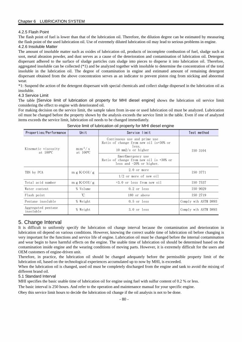
- 80 -
4.2.5 Flash Point The flash point of fuel is lower than that of the lubrication oil. Therefore, the dilution degree can be estimated by measuring the flash point of the used lubrication oil. Use of extremely diluted lubrication oil may lead to serious problems in engine. 4.2.6 Insoluble Matter The amount of insoluble matter such as oxides of lubrication oil, products of incomplete combustion of fuel, sludge such as soot, metal abrasion powder, and dust serves as a cause of the deterioration and contamination of lubrication oil. Detergent dispersant adhered to the surface of sludge particles cuts sludge into pieces to disperse it into lubrication oil. Therefore, aggregated insoluble can be collected (*1) and be analyzed together with insoluble to determine the concentration of the total insoluble in the lubrication oil. The degree of contamination in engine and estimated amount of remaining detergent dispersant obtained from the above concentration serves as an indicator to prevent piston ring from sticking and abnormal wear. *1: Suspend the action of the detergent dispersant with special chemicals and collect sludge dispersed in the lubrication oil as insoluble. 4.3 Service Limit The table [Service limit of lubrication oil property for MHI diesel engine] shows the lubrication oil service limit considering the effect to engine with deteriorated oil. For making decision on the service limit, the sample taken from in-use or used lubrication oil must be analyzed. Lubrication oil must be changed before the property shown by the analysis exceeds the service limit in the table. Even if one of analyzed items exceeds the service limit, lubrication oil needs to be changed immediately.
Service limit of lubrication oil property for MHI diesel engine
Properties/Performance Unit Service limit Test method
Continuous use and prime use iRatio of change from new oil is+30% or
less. 10 mm2/s or higher Kinematic viscosity
at 100ºC mm2/s at 100ºC
EmerEmergency use
iRatio of change from new oil is +30% or less and -20% or higher.
ISO 3104
2.0 or more TBN by PCA mgKOH/g
1/2 or more of new oil ISO 3771
Total acid number mgKOH/g +3.0 or less from new oil ISO 7537
Water content % Volume 0.2 or less ISO 9029
Flash point ℃ 180 or above ISO 2719
Pentane insoluble % Weight 0.5 or less Comply wih ASTM D893
Aggregated pentane insoluble
% Weight 3.0 or less Comply wih ASTM D893
5. Change Interval It is difficult to uniformly specify the lubrication oil change interval because the contamination and deterioration in lubrication oil depend on various conditions. However, knowing the correct usable time of lubrication oil before changing is very important for the functions and service life of engine. Lubrication oil must be changed before the internal contamination and wear begin to have harmful effects on the engine. The usable time of lubrication oil should be determined based on the contamination inside engine and the wearing conditions of moving parts. However, it is extremely difficult for the users and OEM customers of engine-driven unit. Therefore, in practice, the lubrication oil should be changed adequately before the permissible property limit of the lubrication oil, based on the technological experiences accumulated up to now by MHI, is exceeded. When the lubrication oil is changed, used oil must be completely discharged from the engine and tank to avoid the mixing of different brand oil. 5.1 Standard Interval MHI specifies the basic usable time of lubrication oil for engine using fuel with sulfur content of 0.2 % or less. The basic interval is 250 hours. And refer to the operation and maintenance manual for your specific engine. Obey this service limit hours to decide the lubrication oil change if the oil analysis is not to be done.
Chapter 6 LUBRICATION SYSTEM
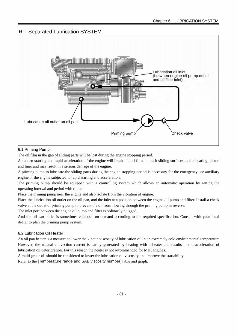
- 81 -
6.Separated Lubrication SYSTEM
6.1 Priming Pump The oil film in the gap of sliding parts will be lost during the engine stopping period. A sudden starting and rapid acceleration of the engine will break the oil films in such sliding surfaces as the bearing, piston and liner and may result in a serious damage of the engine. A priming pump to lubricate the sliding parts during the engine stopping period is necessary for the emergency use auxiliary engine or the engine subjected to rapid starting and acceleration. The priming pump should be equipped with a controlling system which allows an automatic operation by setting the operating interval and period with timer. Place the priming pump near the engine and also isolate from the vibration of engine. Place the lubrication oil outlet on the oil pan, and the inlet at a position between the engine oil pump and filter. Install a check valve at the outlet of priming pump to prevent the oil from flowing through the priming pump in reverse. The inlet port between the engine oil pump and filter is ordinarily plugged. And the oil pan outlet is sometimes equipped on demand according to the required specification. Consult with your local dealer to plan the priming pump system.
6.2 Lubrication Oil Heater An oil pan heater is a measure to lower the kinetic viscosity of lubrication oil in an extremely cold environmental temperature. However, the natural convection current is hardly generated by heating with a heater and results in the acceleration of lubrication oil deterioration. For this reason the heater is not recommended for MHI engines. A multi-grade oil should be considered to lower the lubrication oil viscosity and improve the startability. Refer to the [Temperature range and SAE viscosity number] table and graph.
Chapter 6 LUBRICATION SYSTEM

- 82 -
- 83 -
1. Exhaust System 1.1 Types of Exhausting Device The exhaust device in marine engine has two types. ○ Dry type exhaust line – heat insulation required ○ Wet type exhaust line
The dry type is usually used for marine engines.
The dry type is easy to maintain and has a long life with durability. The exhaust line requires a heat insulation treatment. The insulation is for the safety of personnel and avoids effect of exhaust temperature to the engine performance from the heat in the engine room as the exhaust pipe surface temperature is very high.
In the case of wet type exhaust system, the cooling water used for the engine heat exchange is sprayed into the exhaust line and cools the exhaust gas. The water is exhausted with the gas. The exhaust temperature is significantly lowered with the supplied water in the exhaust line. Elastic rubber hose can be used for the exhaust piping connector. Also, the wet type system does not require the insulation treatment as the heat radiation from the exhaust pipe is low. The key point to adopt the wet type exhaust system is a proper designing of the exhaust line to prevent the engine from the intrusion of cooling water such as seawater flowing backward. CAUTION The designing and construction must be proper so that the back pressure (resistance) of exhaust gas flow in the pipe may be the engine allowable value or lower. Refer to the specification sheet of each engine or the technical data for the value of allowable back pressure. Pay attention to the overheating of facility installed near the engine exhaust line. Construct the piping to prevent the exhaust gas from entering into the cabin.
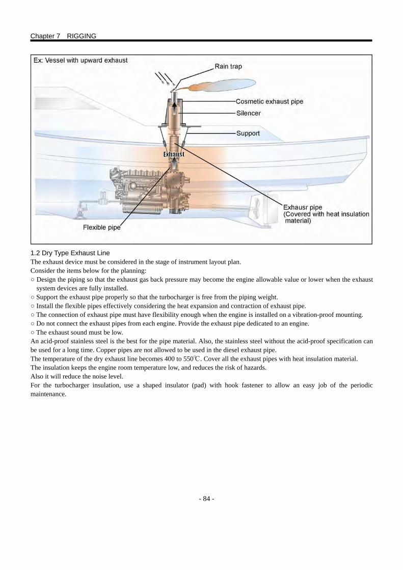
- 84 -
1.2 Dry Type Exhaust Line The exhaust device must be considered in the stage of instrument layout plan. Consider the items below for the planning: ○ Design the piping so that the exhaust gas back pressure may become the engine allowable value or lower when the exhaust
system devices are fully installed. ○ Support the exhaust pipe properly so that the turbocharger is free from the piping weight. ○ Install the flexible pipes effectively considering the heat expansion and contraction of exhaust pipe. ○ The connection of exhaust pipe must have flexibility enough when the engine is installed on a vibration-proof mounting. ○ Do not connect the exhaust pipes from each engine. Provide the exhaust pipe dedicated to an engine. ○ The exhaust sound must be low. An acid-proof stainless steel is the best for the pipe material. Also, the stainless steel without the acid-proof specification can be used for a long time. Copper pipes are not allowed to be used in the diesel exhaust pipe. The temperature of the dry exhaust line becomes 400 to 550℃. Cover all the exhaust pipes with heat insulation material. The insulation keeps the engine room temperature low, and reduces the risk of hazards. Also it will reduce the noise level. For the turbocharger insulation, use a shaped insulator (pad) with hook fastener to allow an easy job of the periodic maintenance.
Chapter 7 RIGGING
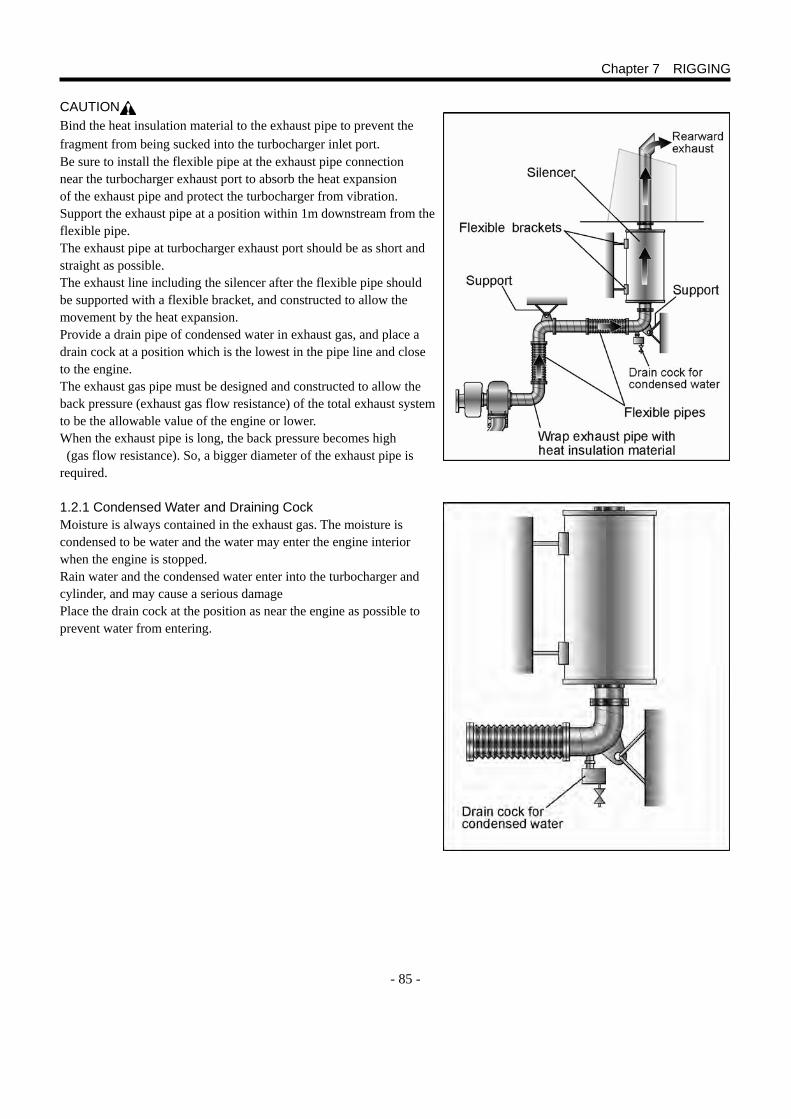
- 85 -
CAUTION Bind the heat insulation material to the exhaust pipe to prevent the fragment from being sucked into the turbocharger inlet port. Be sure to install the flexible pipe at the exhaust pipe connection near the turbocharger exhaust port to absorb the heat expansion of the exhaust pipe and protect the turbocharger from vibration. Support the exhaust pipe at a position within 1m downstream from the flexible pipe. The exhaust pipe at turbocharger exhaust port should be as short and straight as possible. The exhaust line including the silencer after the flexible pipe should be supported with a flexible bracket, and constructed to allow the movement by the heat expansion. Provide a drain pipe of condensed water in exhaust gas, and place a drain cock at a position which is the lowest in the pipe line and close to the engine. The exhaust gas pipe must be designed and constructed to allow the back pressure (exhaust gas flow resistance) of the total exhaust system to be the allowable value of the engine or lower. When the exhaust pipe is long, the back pressure becomes high (gas flow resistance). So, a bigger diameter of the exhaust pipe is required.
1.2.1 Condensed Water and Draining Cock Moisture is always contained in the exhaust gas. The moisture is condensed to be water and the water may enter the engine interior when the engine is stopped. Rain water and the condensed water enter into the turbocharger and cylinder, and may cause a serious damage Place the drain cock at the position as near the engine as possible to prevent water from entering.
Chapter 7 RIGGING
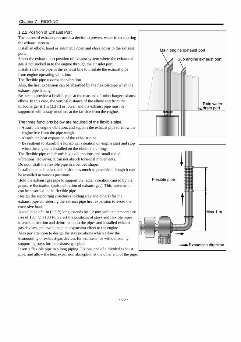
- 86 -
1.2.2 Position of Exhaust Port The outboard exhaust port needs a device to prevent water from entering the exhaust system. Install an elbow, hood or automatic open and close cover to the exhaust port. Select the exhaust port position of exhaust system where the exhausted gas is not sucked in to the engine through the air inlet port. Install a flexible pipe in the exhaust line to insulate the exhaust pipe from engine operating vibration. The flexible pipe absorbs the vibration. Also, the heat expansion can be absorbed by the flexible pipe when the exhaust pipe is long. Be sure to provide a flexible pipe at the rear end of turbocharger exhaust elbow. In this case, the vertical distance of the elbow end from the turbocharger is 1m (3.3 ft) or lower, and the exhaust pipe must be supported with a stay or others at the far side from the engine.
The three functions below are required of the flexible pipe. ○ Absorb the engine vibration, and support the exhaust pipe to allow the
engine free from the pipe weigh. ○ Absorb the heat expansion of the exhaust pipe. ○ Be resilient to absorb the horizontal vibration on engine start and stop
when the engine is installed on the elastic mountings. The flexible pipe can absorb big axial motions and small radial vibrations. However, it can not absorb torsional movements. Do not install the flexible pipe in a bended shape. Install the pipe in a vertical position as much as possible although it can be installed in various positions. Hold the exhaust gas pipe to support the radial vibration caused by the pressure fluctuation (pulse vibration of exhaust gas). This movement can be absorbed in the flexible pipe. Design the supporting structure (holding stay and others) for the exhaust pipe considering the exhaust pipe heat expansion to avoid the excessive load. A steel pipe of 1 m (3.3 ft) long extends by 1.2 mm with the temperature rise of 100 ℃ [108 F]. Select the positions of stays and flexible pipes to avoid distortion and deformation to the pipes and installed exhaust gas devises, and avoid the pipe expansion effect to the engine. Also pay attention to design the stay positions which allow the dismounting of exhaust gas devices for maintenance without adding supporting stays for the exhaust gas pipe. Insert a flexible pipe in a long piping. Fix one end of a divided exhaust pipe, and allow the heat expansion absorption at the other end of the pipe.
Chapter 7 RIGGING
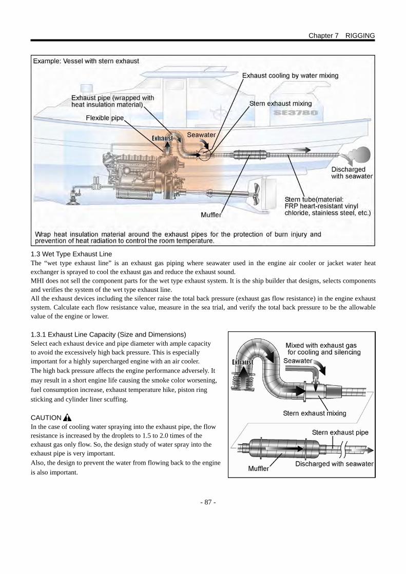
- 87 -
1.3 Wet Type Exhaust Line The “wet type exhaust line” is an exhaust gas piping where seawater used in the engine air cooler or jacket water heat exchanger is sprayed to cool the exhaust gas and reduce the exhaust sound. MHI does not sell the component parts for the wet type exhaust system. It is the ship builder that designs, selects components and verifies the system of the wet type exhaust line. All the exhaust devices including the silencer raise the total back pressure (exhaust gas flow resistance) in the engine exhaust system. Calculate each flow resistance value, measure in the sea trial, and verify the total back pressure to be the allowable value of the engine or lower. 1.3.1 Exhaust Line Capacity (Size and Dimensions) Select each exhaust device and pipe diameter with ample capacity to avoid the excessively high back pressure. This is especially important for a highly supercharged engine with an air cooler. The high back pressure affects the engine performance adversely. It may result in a short engine life causing the smoke color worsening, fuel consumption increase, exhaust temperature hike, piston ring sticking and cylinder liner scuffing.
CAUTION In the case of cooling water spraying into the exhaust pipe, the flow resistance is increased by the droplets to 1.5 to 2.0 times of the exhaust gas only flow. So, the design study of water spray into the exhaust pipe is very important. Also, the design to prevent the water from flowing back to the engine is also important.
Chapter 7 RIGGING
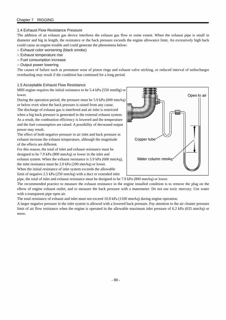
- 88 -
1.4 Exhaust Flow Resistance Pressure The addition of an exhaust gas device interferes the exhaust gas flow to some extent. When the exhaust pipe is small in diameter and big in length, the resistance or the back pressure exceeds the engine allowance limit. An excessively high back could cause an engine trouble and could generate the phenomena below: ○ Exhaust color worsening (black smoke) ○ Exhaust temperature rise ○ Fuel consumption increase ○ Output power lowering The causes of failure such as premature wear of piston rings and exhaust valve sticking, or reduced interval of turbocharger overhauling may result if the condition has continued for a long period.
1.5 Acceptable Exhaust Flow Resistance MHI engine requires the initial resistance to be 5.4 kPa (550 mmHg) or lower. During the operation period, the pressure must be 5.9 kPa (600 mmAq) or below even when the back pressure is raised from any cause. The discharge of exhaust gas is interfered and air inlet is restricted when a big back pressure is generated in the external exhaust system. As a result, the combustion efficiency is lowered and the temperature and the fuel consumption are raised. A possibility of decreased output power may result. The effect of both negative pressure in air inlet and back pressure in exhaust increase the exhaust temperature, although the magnitude of the effects are different. For this reason, the total of inlet and exhaust resistance must be designed to be 7.9 kPa (800 mmAq) or lower in the inlet and exhaust system. When the exhaust resistance is 5.9 kPa (600 mmAq), the inlet resistance must be 2.0 kPa (200 mmAq) or lower. When the initial resistance of inlet system exceeds the allowable limit of negative 2.5 kPa (250 mmAq) with a duct or extended inlet pipe, the total of inlet and exhaust resistance must be designed to be 7.9 kPa (800 mmAq) or lower. The recommended practice to measure the exhaust resistance in the engine installed condition is to remove the plug on the elbow of engine exhaust outlet, and to measure the back pressure with a manometer. Do not use toxic mercury. Use water with a transparent pipe open air. The total resistance of exhaust and inlet must not exceed 10.8 kPa (1100 mmAq) during engine operation. A larger negative pressure in the inlet system is allowed with a lowered back pressure. Pay attention to the air cleaner pressure limit of air flow resistance when the engine is operated in the allowable maximum inlet pressure of 6.2 kPa (635 mmAq) or more.
Chapter 7 RIGGING
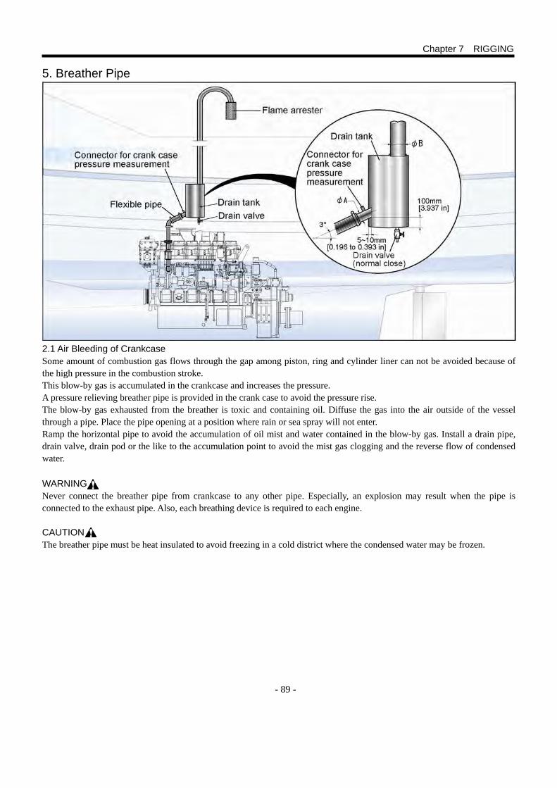
- 89 -
5. Breather Pipe 2.1 Air Bleeding of Crankcase Some amount of combustion gas flows through the gap among piston, ring and cylinder liner can not be avoided because of the high pressure in the combustion stroke. This blow-by gas is accumulated in the crankcase and increases the pressure. A pressure relieving breather pipe is provided in the crank case to avoid the pressure rise. The blow-by gas exhausted from the breather is toxic and containing oil. Diffuse the gas into the air outside of the vessel through a pipe. Place the pipe opening at a position where rain or sea spray will not enter. Ramp the horizontal pipe to avoid the accumulation of oil mist and water contained in the blow-by gas. Install a drain pipe, drain valve, drain pod or the like to the accumulation point to avoid the mist gas clogging and the reverse flow of condensed water. WARNING Never connect the breather pipe from crankcase to any other pipe. Especially, an explosion may result when the pipe is connected to the exhaust pipe. Also, each breathing device is required to each engine.
CAUTION The breather pipe must be heat insulated to avoid freezing in a cold district where the condensed water may be frozen.
Chapter 7 RIGGING
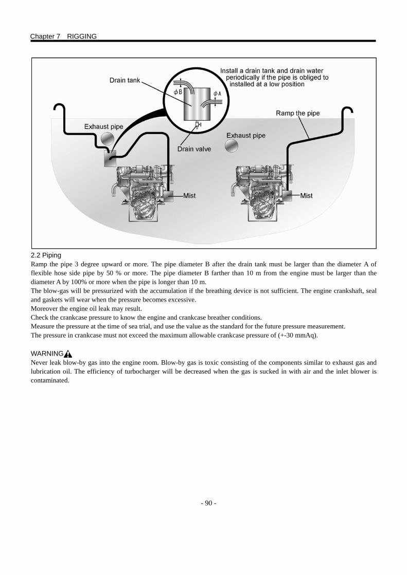
- 90 -
2.2 Piping Ramp the pipe 3 degree upward or more. The pipe diameter B after the drain tank must be larger than the diameter A of flexible hose side pipe by 50 % or more. The pipe diameter B farther than 10 m from the engine must be larger than the diameter A by 100% or more when the pipe is longer than 10 m. The blow-gas will be pressurized with the accumulation if the breathing device is not sufficient. The engine crankshaft, seal and gaskets will wear when the pressure becomes excessive. Moreover the engine oil leak may result. Check the crankcase pressure to know the engine and crankcase breather conditions. Measure the pressure at the time of sea trial, and use the value as the standard for the future pressure measurement. The pressure in crankcase must not exceed the maximum allowable crankcase pressure of (+-30 mmAq).
WARNING Never leak blow-by gas into the engine room. Blow-by gas is toxic consisting of the components similar to exhaust gas and lubrication oil. The efficiency of turbocharger will be decreased when the gas is sucked in with air and the inlet blower is contaminated.
Chapter 7 RIGGING
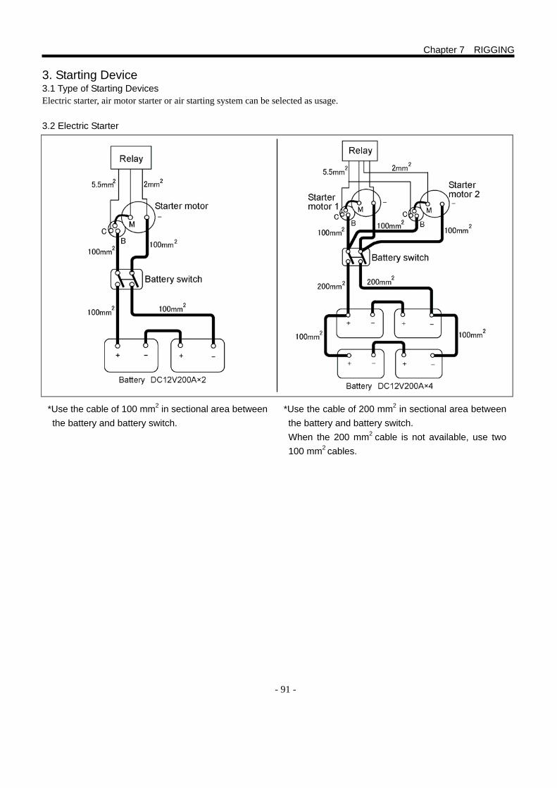
- 91 -
3. Starting Device 3.1 Type of Starting Devices Electric starter, air motor starter or air starting system can be selected as usage. 3.2 Electric Starter
Chapter 7 RIGGING
*Use the cable of 100 mm2 in sectional area between the battery and battery switch.
*Use the cable of 200 mm2 in sectional area between the battery and battery switch. When the 200 mm2 cable is not available, use two 100 mm2 cables.
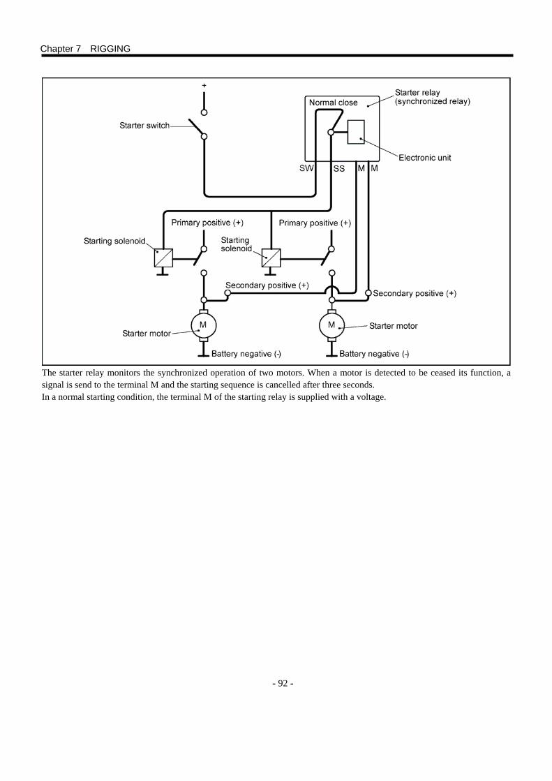
- 92 -
The starter relay monitors the synchronized operation of two motors. When a motor is detected to be ceased its function, a signal is send to the terminal M and the starting sequence is cancelled after three seconds. In a normal starting condition, the terminal M of the starting relay is supplied with a voltage.
Chapter 7 RIGGING
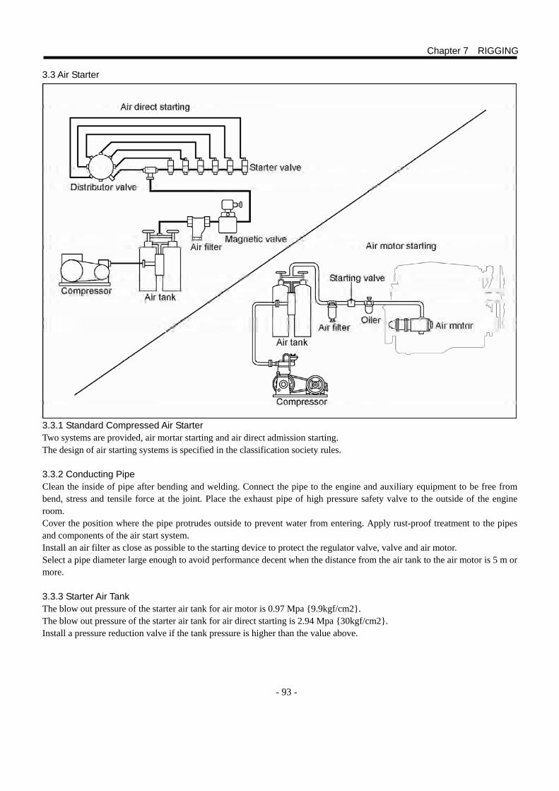
- 93 -
3.3 Air Starter 3.3.1 Standard Compressed Air Starter Two systems are provided, air mortar starting and air direct admission starting. The design of air starting systems is specified in the classification society rules. 3.3.2 Conducting Pipe Clean the inside of pipe after bending and welding. Connect the pipe to the engine and auxiliary equipment to be free from bend, stress and tensile force at the joint. Place the exhaust pipe of high pressure safety valve to the outside of the engine room. Cover the position where the pipe protrudes outside to prevent water from entering. Apply rust-proof treatment to the pipes and components of the air start system. Install an air filter as close as possible to the starting device to protect the regulator valve, valve and air motor. Select a pipe diameter large enough to avoid performance decent when the distance from the air tank to the air motor is 5 m or more. 3.3.3 Starter Air Tank The blow out pressure of the starter air tank for air motor is 0.97 Mpa {9.9kgf/cm2}. The blow out pressure of the starter air tank for air direct starting is 2.94 Mpa {30kgf/cm2}. Install a pressure reduction valve if the tank pressure is higher than the value above.
Chapter 7 RIGGING
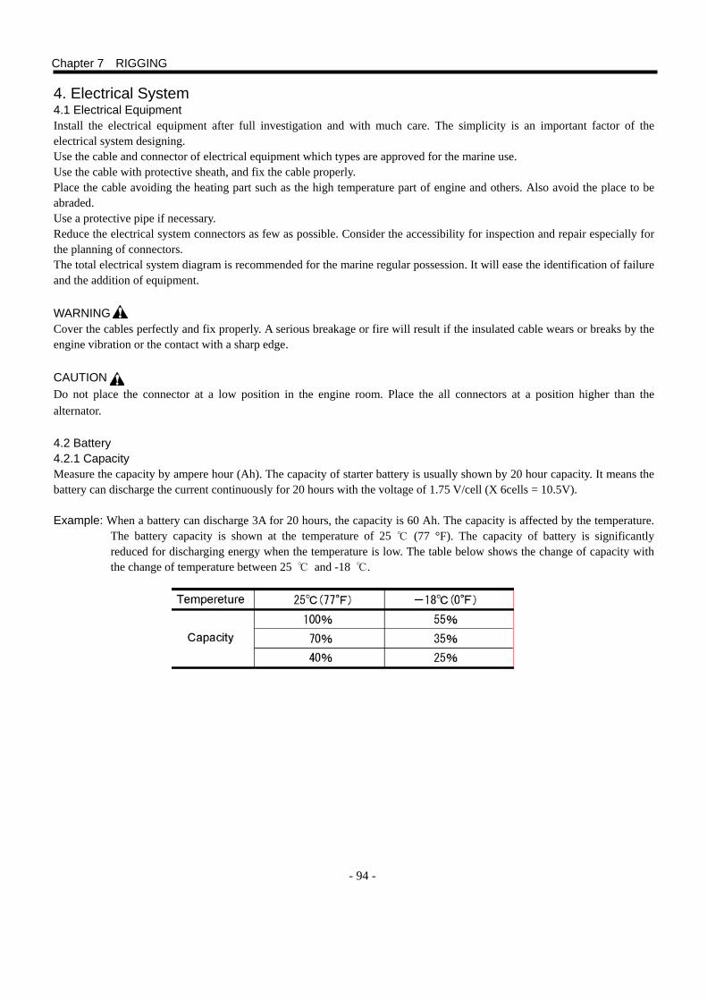
- 94 -
4. Electrical System 4.1 Electrical Equipment Install the electrical equipment after full investigation and with much care. The simplicity is an important factor of the electrical system designing. Use the cable and connector of electrical equipment which types are approved for the marine use. Use the cable with protective sheath, and fix the cable properly. Place the cable avoiding the heating part such as the high temperature part of engine and others. Also avoid the place to be abraded. Use a protective pipe if necessary. Reduce the electrical system connectors as few as possible. Consider the accessibility for inspection and repair especially for the planning of connectors. The total electrical system diagram is recommended for the marine regular possession. It will ease the identification of failure and the addition of equipment.
WARNING Cover the cables perfectly and fix properly. A serious breakage or fire will result if the insulated cable wears or breaks by the engine vibration or the contact with a sharp edge. CAUTION Do not place the connector at a low position in the engine room. Place the all connectors at a position higher than the alternator. 4.2 Battery 4.2.1 Capacity Measure the capacity by ampere hour (Ah). The capacity of starter battery is usually shown by 20 hour capacity. It means the battery can discharge the current continuously for 20 hours with the voltage of 1.75 V/cell (X 6cells = 10.5V). Example: When a battery can discharge 3A for 20 hours, the capacity is 60 Ah. The capacity is affected by the temperature.
The battery capacity is shown at the temperature of 25 ℃ (77 °F). The capacity of battery is significantly reduced for discharging energy when the temperature is low. The table below shows the change of capacity with the change of temperature between 25 ℃ and -18 ℃.
Chapter 7 RIGGING
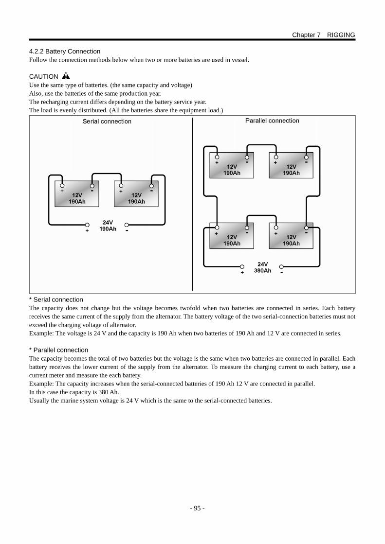
- 95 -
4.2.2 Battery Connection Follow the connection methods below when two or more batteries are used in vessel. CAUTION Use the same type of batteries. (the same capacity and voltage) Also, use the batteries of the same production year. The recharging current differs depending on the battery service year. The load is evenly distributed. (All the batteries share the equipment load.)
* Serial connection The capacity does not change but the voltage becomes twofold when two batteries are connected in series. Each battery receives the same current of the supply from the alternator. The battery voltage of the two serial-connection batteries must not exceed the charging voltage of alternator. Example: The voltage is 24 V and the capacity is 190 Ah when two batteries of 190 Ah and 12 V are connected in series. * Parallel connection The capacity becomes the total of two batteries but the voltage is the same when two batteries are connected in parallel. Each battery receives the lower current of the supply from the alternator. To measure the charging current to each battery, use a current meter and measure the each battery. Example: The capacity increases when the serial-connected batteries of 190 Ah 12 V are connected in parallel. In this case the capacity is 380 Ah. Usually the marine system voltage is 24 V which is the same to the serial-connected batteries.
Chapter 7 RIGGING
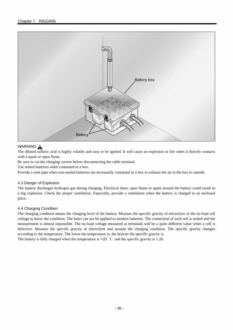
- 96 -
WARNING The diluted sulfuric acid is highly volatile and easy to be ignited. It will cause an explosion or fire when it directly contacts with a spark or open flame. Be sure to cut the charging current before disconnecting the cable terminal. Use sealed batteries when contained in a box. Provide a vent pipe when non-sealed batteries are necessarily contained in a box to exhaust the air in the box to outside.
4.3 Danger of Explosion The battery discharges hydrogen gas during charging. Electrical short, open flame or spark around the battery could result in a big explosion. Check the proper ventilation. Especially, provide a ventilation when the battery is charged in an enclosed place. 4.4 Charging Condition The charging condition means the charging level of the battery. Measure the specific gravity of electrolyte or the no-load cell voltage to know the condition. The latter can not be applied to modern batteries. The connection of each sell is sealed and the measurement is almost impossible. The no-load voltage measured at terminals will be a quite different value when a cell is defective. Measure the specific gravity of electrolyte and assume the charging condition. The specific gravity changes according to the temperature. The lower the temperature is, the heavier the specific gravity is. The battery is fully charged when the temperature is +25 ℃ and the specific gravity is 1.28.
Chapter 7 RIGGING
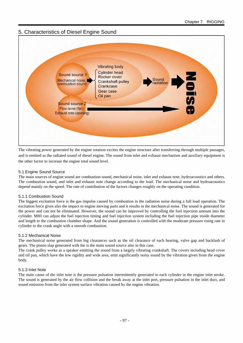
- 97 -
5. Characteristics of Diesel Engine Sound The excitation force generated by the engine rotation excites the engine structure through various pathways. The excited structure creates radiated sounds to our ears as diesel engine sound. The vibrating power generated by the engine rotation excites the engine structure after transferring through multiple passages, and is emitted as the radiated sound of diesel engine. The sound from inlet and exhaust mechanism and auxiliary equipment is the other factor to increase the engine total sound level. 5.1 Engine Sound Source The main sources of engine sound are combustion sound, mechanical noise, inlet and exhaust note, hydroacoustics and others. The combustion sound, and inlet and exhaust note change according to the load. The mechanical noise and hydroacoustics depend mainly on the speed. The rate of contribution of the factors changes roughly on the operating condition. 5.1.1 Combustion Sound The biggest excitation force is the gas impulse caused by combustion in the radiation noise during a full load operation. The excitation force gives also the impact to engine moving parts and it results in the mechanical noise. The sound is generated for the power and can not be eliminated. However, the sound can be improved by controlling the fuel injection amount into the cylinder. MHI can adjust the fuel injection timing and fuel injection system including the fuel injection pipe inside diameter and length to the combustion chamber shape. And the sound generation is controlled with the moderate pressure rising rate in cylinder to the crank angle with a smooth combustion. 5.1.2 Mechanical Noise The mechanical noise generated from big clearances such as the oil clearance of each bearing, valve gap and backlash of gears. The piston slap generated with the is the main sound source also in this case. The crank pulley works as a speaker emitting the sound from a largely vibrating crankshaft. The covers including head cover and oil pan, which have the low rigidity and wide area, emit significantly noisy sound by the vibration given from the engine body. 5.1.3 Inlet Note The main cause of the inlet note is the pressure pulsation intermittently generated in each cylinder in the engine inlet stroke. The sound is generated by the air flow collision and the break away at the inlet port, pressure pulsation in the inlet duct, and sound emission from the inlet system surface vibration caused by the engine vibration.
Chapter 7 RIGGING
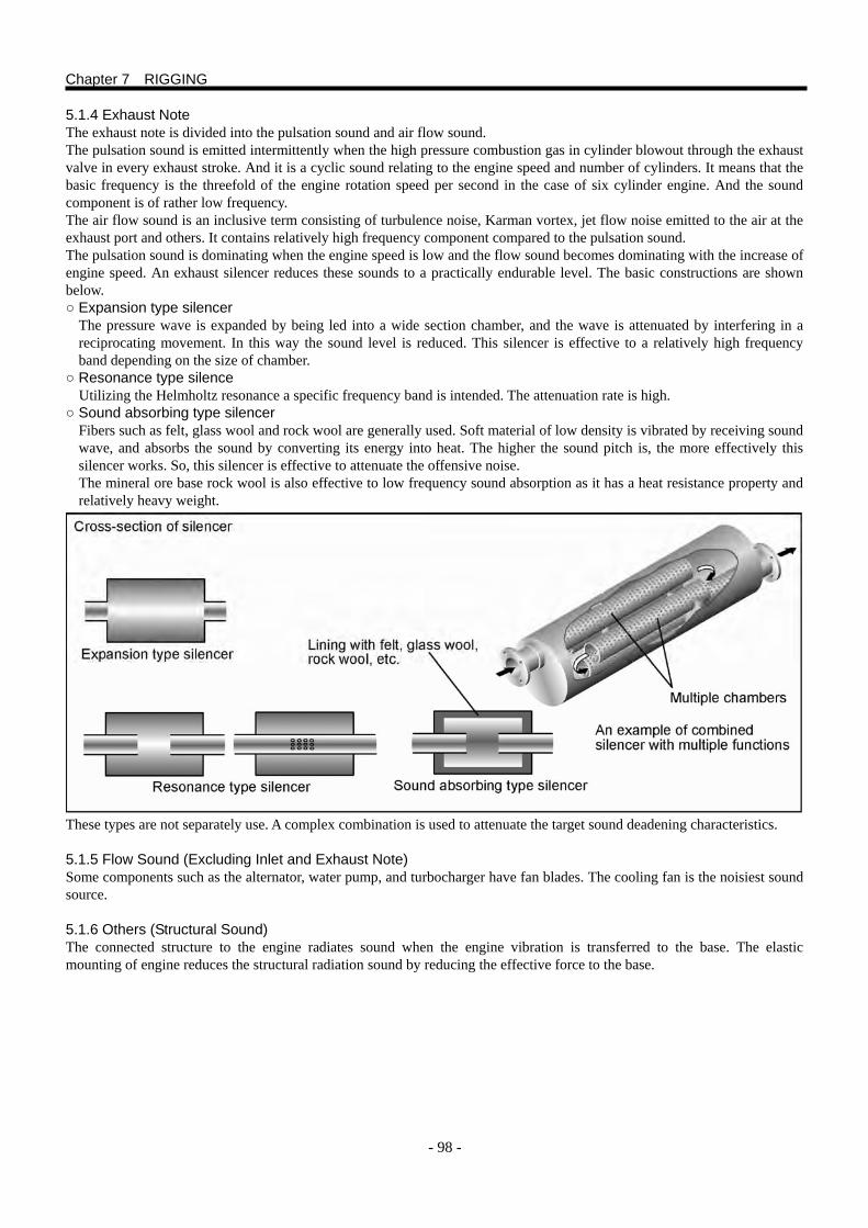
- 98 -
5.1.4 Exhaust Note The exhaust note is divided into the pulsation sound and air flow sound. The pulsation sound is emitted intermittently when the high pressure combustion gas in cylinder blowout through the exhaust valve in every exhaust stroke. And it is a cyclic sound relating to the engine speed and number of cylinders. It means that the basic frequency is the threefold of the engine rotation speed per second in the case of six cylinder engine. And the sound component is of rather low frequency. The air flow sound is an inclusive term consisting of turbulence noise, Karman vortex, jet flow noise emitted to the air at the exhaust port and others. It contains relatively high frequency component compared to the pulsation sound. The pulsation sound is dominating when the engine speed is low and the flow sound becomes dominating with the increase of engine speed. An exhaust silencer reduces these sounds to a practically endurable level. The basic constructions are shown below. ○ Expansion type silencer
The pressure wave is expanded by being led into a wide section chamber, and the wave is attenuated by interfering in a reciprocating movement. In this way the sound level is reduced. This silencer is effective to a relatively high frequency band depending on the size of chamber.
○ Resonance type silence Utilizing the Helmholtz resonance a specific frequency band is intended. The attenuation rate is high.
○ Sound absorbing type silencer Fibers such as felt, glass wool and rock wool are generally used. Soft material of low density is vibrated by receiving sound wave, and absorbs the sound by converting its energy into heat. The higher the sound pitch is, the more effectively this silencer works. So, this silencer is effective to attenuate the offensive noise. The mineral ore base rock wool is also effective to low frequency sound absorption as it has a heat resistance property and relatively heavy weight.
These types are not separately use. A complex combination is used to attenuate the target sound deadening characteristics. 5.1.5 Flow Sound (Excluding Inlet and Exhaust Note) Some components such as the alternator, water pump, and turbocharger have fan blades. The cooling fan is the noisiest sound source. 5.1.6 Others (Structural Sound) The connected structure to the engine radiates sound when the engine vibration is transferred to the base. The elastic mounting of engine reduces the structural radiation sound by reducing the effective force to the base.
Chapter 7 RIGGING
- 99 -
6. Ventilation of Engine Room 6.1 Engine Performance The engine output power varies depending on the engine working environment (working condition). Pay attention to the working environment because the durability of the engine is also affected as the power. The amount of air for combustion is reduced when the atmospheric pressure decreases and the air density is lowered. The increases of black smoke, exhaust gas temperature and fuel consumption are the result. The maximum torque of the engine is decreased as the output at a volume of fuel becomes low. Also pay attention to the turbocharger rotation speed limit as the speed is increased with the lower turbocharger exhaust pressure. When the environmental temperature becomes high, the exhaust temperature increases with the reduced air mass as the rise of air temperature for combustion. In the case of highly supercharged engine with air cooler, pay attention to the exhaust temperature as the temperature rises 1.5 to 2 times as high as that of inlet air temperature. The exhaust pressure of turbocharger (exhaust back pressure) increases when the flow resistance of pipe and exhaust muffler is increased. And, the turbocharger rotation speed is decreased as the pressure difference between the turbocharger inlet and exhaust is decreased. The amount of black smoke and exhaust temperature increases with the reduced amount of air for combustion. Then the increase of fuel consumption is the result. The diesel engine requires much amount of air for combustion. When the amount of air is not sufficient, black smoke appears first. Then the exhaust temperature rises, and the fuel consumption increases. This phenomenon is significant at the maximum torque operation. Provide the inlet and exhaust duct capacity to be enough, and inlet and exhaust resistances to be the allowable limit or below for the proper function, and satisfying performance and power of the engine. 6.2 For the Engine Room Ventilation, Satisfy the Condition Below: ○ Supply the air amount enough for the engine combustion. ○ Be sure to ventilate the engine room to keep the temperature in engine room in an allowable range. Supply air enough to
avid the pressure in the engine room to become a negative pressure. The ventilation is also important to keep the temperature of electric appliances and injection system of the engine at a low level, and to cool down the engine total body. Install ventilating facilities such as the air vent and ventilator which have an ample capacity for safety when personnel assignment is necessary. NOTE: Obey the local safety rules and legal requirements.
Also obey the proper classification society standards if necessary. 6.3 Engine Output Power and Air Temperature for Combustion The standard atmospheric condition at which MHI guarantees the indicated rate output is as below: Atmospheric temperature is 298 K (25 ℃), atmospheric pressure 100 kPa (1000 mbar), relative humidity 30 %, seawater temperature 305 K (32 ℃) and fuel temperature 313 K (40 ℃). These standards are specified in the international standard ISO-3046-1 and domestic JIS B 8002-1. The proper air supply for combustion and enough ventilation in the engine room are necessary to ensure the stable engine operation, keep the durability and reliability and gain the indicated rated output. Lower the load and operate the engine at a derated power from the maximum when the air temperature for combustion exceeds 35 ℃. In this case, keep the engine maximum power to be lower than the allowable power. In the case of propulsion engine, control the engine speed to be lower than the rating. In an condition where the atmospheric temperature is always 45 ℃ or higher, lower the rated load. Change the fuel rack set position of the fuel injection pump to reduce the fuel injection amount. Refer to a separately issued manual for details. CAUTION The heat load becomes high if the maximum output operation is kept without reducing the fuel injection amount in an environmental where the temperature is high. A high maintenance cost will be the result by the wear of piston, piston ring, cylinder liner and others, deterioration of lubrication oil, abnormally rapid wear of bearings, and others.
Chapter 7 RIGGING
- 100 -
6.4 Engine Output Power at an Altitude Higher Than 0 m Most of the marine engines are used at an altitude near 0 m. Some lakes have altitudes higher than 0m. Change of the rated power is not required when the engine is operated at an altitude of 1500 m or lower. If the altitude of operation area is higher than 1500 m, the change of the maximum output (reduction of fuel injection amount) is necessary. Refer to a separately issued manual for details. In some cases, the turbocharger capacity, injection nozzle specification, fuel injection timing and others are to be changed. 6.5 Function of Inlet and Exhaust Openings An ample size air inlet opening is necessary for the engine room to secure the amount of air for engine combustion. Ventilation is also necessary to change the room air to atmospheric air to exhaust a certain amount of heat emitted by engine in the engine room. The inlet and exhaust openings must work sufficiently even in a bad weather. Protect them from entering of rain water, wave splash and others. The compressor in turbocharger is sometimes corroded when sea splashes enter through the inlet opening. Pay attention, this may cause the breakage of wheel. Set apart the inlet and exhaust openings in the engine room as far as possible for a smooth air flow. The exhausted gas from the room is sucked into the room and the temperature will rise when the positions of inlet and exhaust openings are too close.
Chapter 7 RIGGING
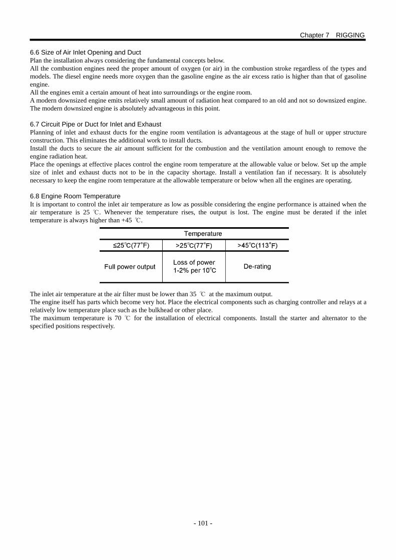
- 101 -
6.6 Size of Air Inlet Opening and Duct Plan the installation always considering the fundamental concepts below. All the combustion engines need the proper amount of oxygen (or air) in the combustion stroke regardless of the types and models. The diesel engine needs more oxygen than the gasoline engine as the air excess ratio is higher than that of gasoline engine. All the engines emit a certain amount of heat into surroundings or the engine room. A modern downsized engine emits relatively small amount of radiation heat compared to an old and not so downsized engine. The modern downsized engine is absolutely advantageous in this point. 6.7 Circuit Pipe or Duct for Inlet and Exhaust Planning of inlet and exhaust ducts for the engine room ventilation is advantageous at the stage of hull or upper structure construction. This eliminates the additional work to install ducts. Install the ducts to secure the air amount sufficient for the combustion and the ventilation amount enough to remove the engine radiation heat. Place the openings at effective places control the engine room temperature at the allowable value or below. Set up the ample size of inlet and exhaust ducts not to be in the capacity shortage. Install a ventilation fan if necessary. It is absolutely necessary to keep the engine room temperature at the allowable temperature or below when all the engines are operating. 6.8 Engine Room Temperature It is important to control the inlet air temperature as low as possible considering the engine performance is attained when the air temperature is 25 ℃. Whenever the temperature rises, the output is lost. The engine must be derated if the inlet temperature is always higher than +45 ℃. The inlet air temperature at the air filter must be lower than 35 ℃ at the maximum output. The engine itself has parts which become very hot. Place the electrical components such as charging controller and relays at a relatively low temperature place such as the bulkhead or other place. The maximum temperature is 70 ℃ for the installation of electrical components. Install the starter and alternator to the specified positions respectively.
Chapter 7 RIGGING
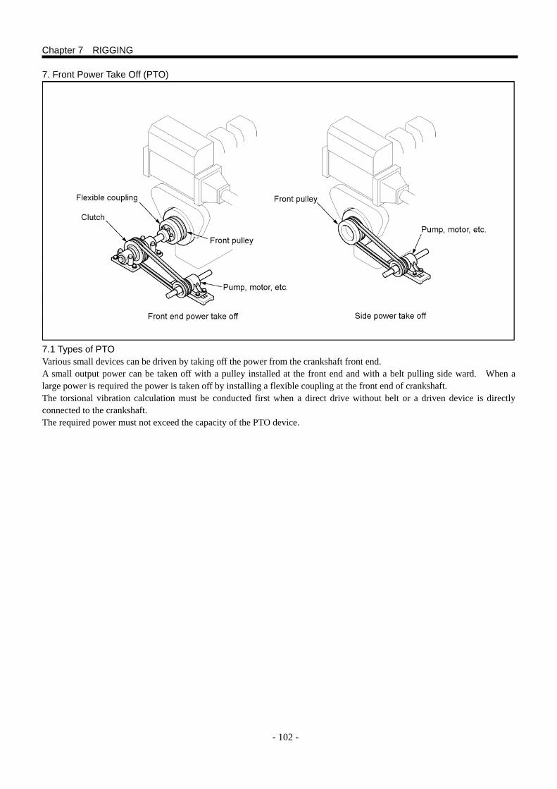
- 102 -
7. Front Power Take Off (PTO) 7.1 Types of PTO Various small devices can be driven by taking off the power from the crankshaft front end. A small output power can be taken off with a pulley installed at the front end and with a belt pulling side ward. When a large power is required the power is taken off by installing a flexible coupling at the front end of crankshaft. The torsional vibration calculation must be conducted first when a direct drive without belt or a driven device is directly connected to the crankshaft. The required power must not exceed the capacity of the PTO device.
Chapter 7 RIGGING
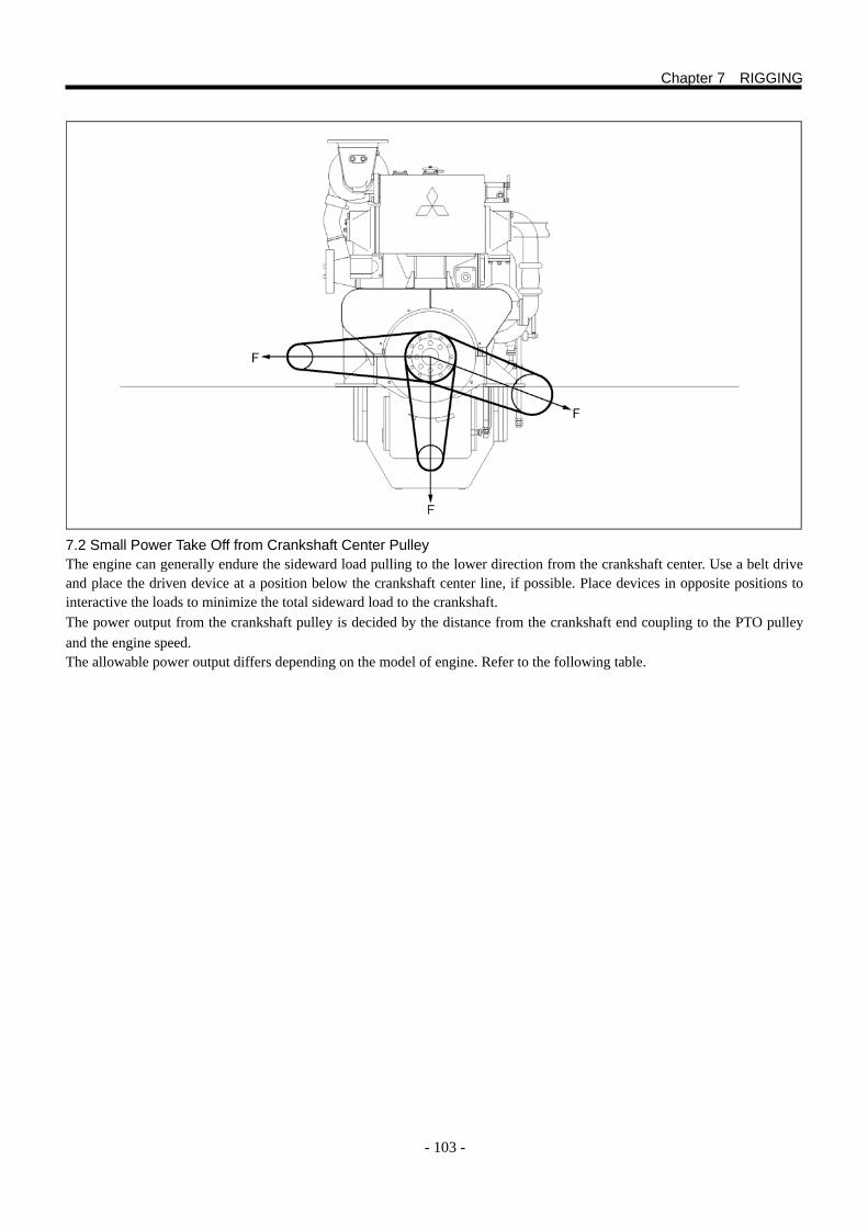
- 103 -
7.2 Small Power Take Off from Crankshaft Center Pulley The engine can generally endure the sideward load pulling to the lower direction from the crankshaft center. Use a belt drive and place the driven device at a position below the crankshaft center line, if possible. Place devices in opposite positions to interactive the loads to minimize the total sideward load to the crankshaft. The power output from the crankshaft pulley is decided by the distance from the crankshaft end coupling to the PTO pulley and the engine speed. The allowable power output differs depending on the model of engine. Refer to the following table.
Chapter 7 RIGGING
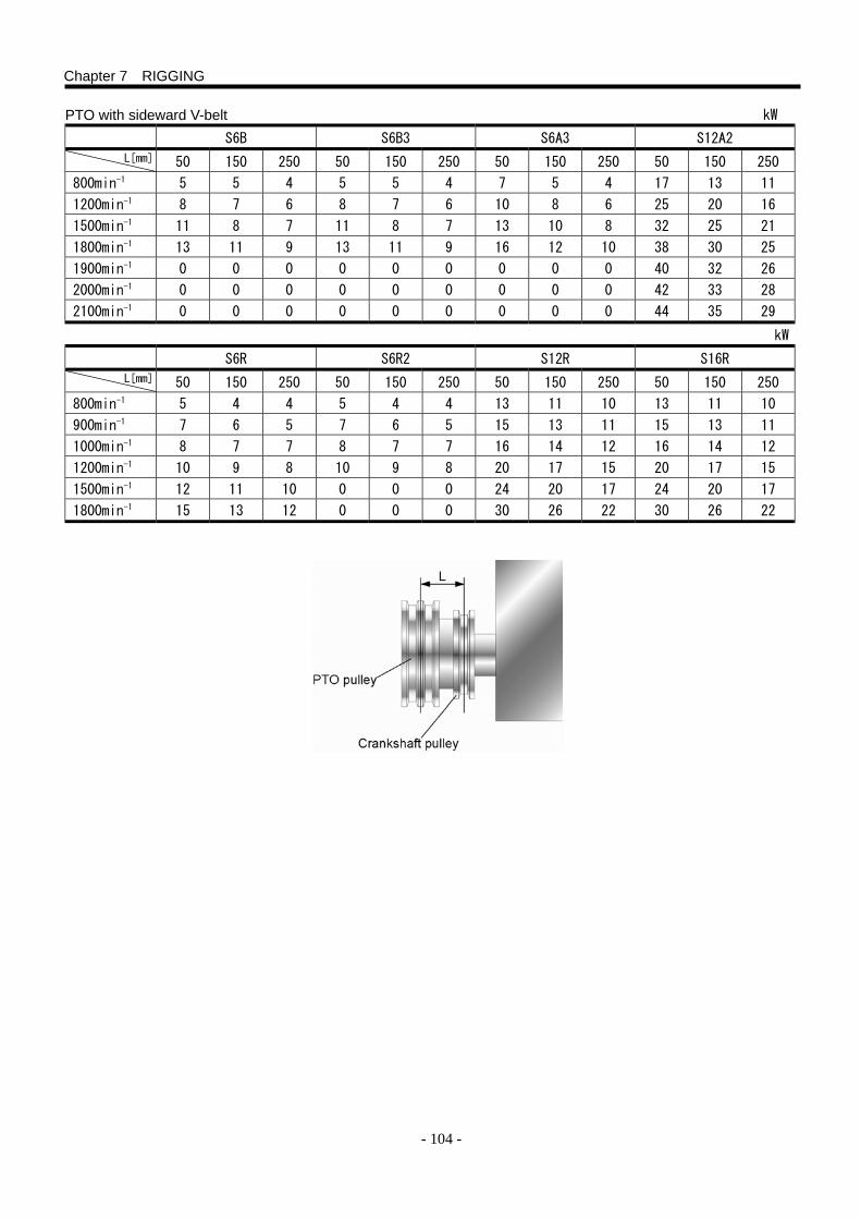
- 104 -
PTO with sideward V-belt kW S6B S6B3 S6A3 S12A2
50 150 250 50 150 250 50 150 250 50 150 250
800min-1 5 5 4 5 5 4 7 5 4 17 13 11
1200min-1 8 7 6 8 7 6 10 8 6 25 20 16
1500min-1 11 8 7 11 8 7 13 10 8 32 25 21
1800min-1 13 11 9 13 11 9 16 12 10 38 30 25
1900min-1 0 0 0 0 0 0 0 0 0 40 32 26
2000min-1 0 0 0 0 0 0 0 0 0 42 33 28
2100min-1 0 0 0 0 0 0 0 0 0 44 35 29
kW S6R S6R2 S12R S16R
50 150 250 50 150 250 50 150 250 50 150 250
800min-1 5 4 4 5 4 4 13 11 10 13 11 10
900min-1 7 6 5 7 6 5 15 13 11 15 13 11
1000min-1 8 7 7 8 7 7 16 14 12 16 14 12
1200min-1 10 9 8 10 9 8 20 17 15 20 17 15
1500min-1 12 11 10 0 0 0 24 20 17 24 20 17
1800min-1 15 13 12 0 0 0 30 26 22 30 26 22
Chapter 7 RIGGING
L[mm]
L[mm]
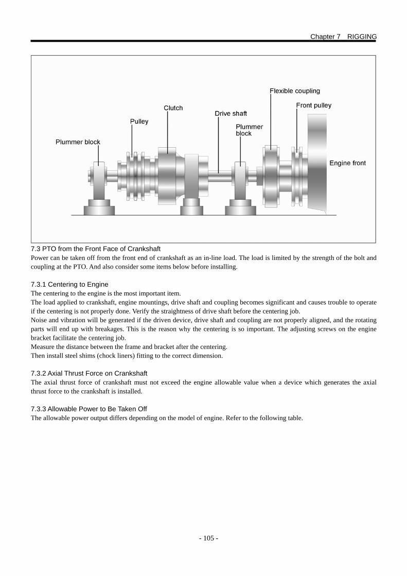
- 105 -
7.3 PTO from the Front Face of Crankshaft Power can be taken off from the front end of crankshaft as an in-line load. The load is limited by the strength of the bolt and coupling at the PTO. And also consider some items below before installing. 7.3.1 Centering to Engine The centering to the engine is the most important item. The load applied to crankshaft, engine mountings, drive shaft and coupling becomes significant and causes trouble to operate if the centering is not properly done. Verify the straightness of drive shaft before the centering job. Noise and vibration will be generated if the driven device, drive shaft and coupling are not properly aligned, and the rotating parts will end up with breakages. This is the reason why the centering is so important. The adjusting screws on the engine bracket facilitate the centering job. Measure the distance between the frame and bracket after the centering. Then install steel shims (chock liners) fitting to the correct dimension. 7.3.2 Axial Thrust Force on Crankshaft The axial thrust force of crankshaft must not exceed the engine allowable value when a device which generates the axial thrust force to the crankshaft is installed. 7.3.3 Allowable Power to Be Taken Off The allowable power output differs depending on the model of engine. Refer to the following table.
Chapter 7 RIGGING
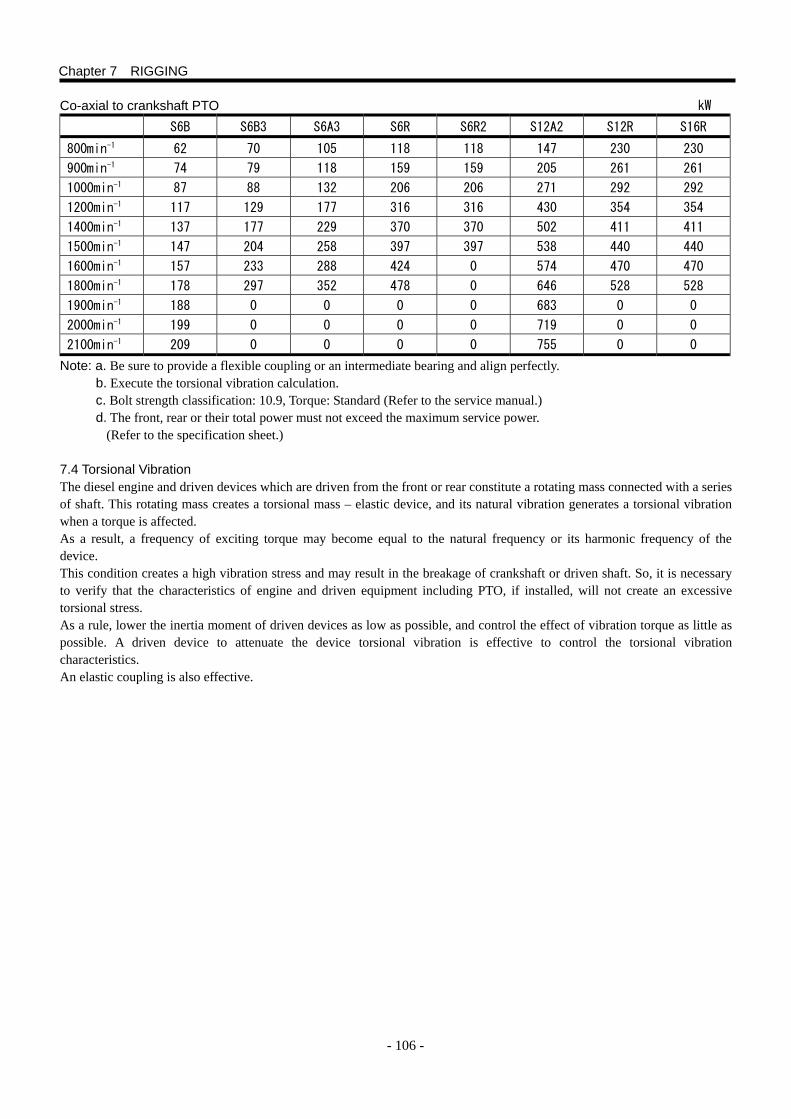
- 106 -
Co-axial to crankshaft PTO kW S6B S6B3 S6A3 S6R S6R2 S12A2 S12R S16R
800min-1 62 70 105 118 118 147 230 230
900min-1 74 79 118 159 159 205 261 261
1000min-1 87 88 132 206 206 271 292 292
1200min-1 117 129 177 316 316 430 354 354
1400min-1 137 177 229 370 370 502 411 411
1500min-1 147 204 258 397 397 538 440 440
1600min-1 157 233 288 424 0 574 470 470
1800min-1 178 297 352 478 0 646 528 528
1900min-1 188 0 0 0 0 683 0 0
2000min-1 199 0 0 0 0 719 0 0
2100min-1 209 0 0 0 0 755 0 0
Note: a. Be sure to provide a flexible coupling or an intermediate bearing and align perfectly. b. Execute the torsional vibration calculation. c. Bolt strength classification: 10.9, Torque: Standard (Refer to the service manual.) d. The front, rear or their total power must not exceed the maximum service power.
(Refer to the specification sheet.) 7.4 Torsional Vibration The diesel engine and driven devices which are driven from the front or rear constitute a rotating mass connected with a series of shaft. This rotating mass creates a torsional mass – elastic device, and its natural vibration generates a torsional vibration when a torque is affected. As a result, a frequency of exciting torque may become equal to the natural frequency or its harmonic frequency of the device. This condition creates a high vibration stress and may result in the breakage of crankshaft or driven shaft. So, it is necessary to verify that the characteristics of engine and driven equipment including PTO, if installed, will not create an excessive torsional stress. As a rule, lower the inertia moment of driven devices as low as possible, and control the effect of vibration torque as little as possible. A driven device to attenuate the device torsional vibration is effective to control the torsional vibration characteristics. An elastic coupling is also effective.
Chapter 7 RIGGING
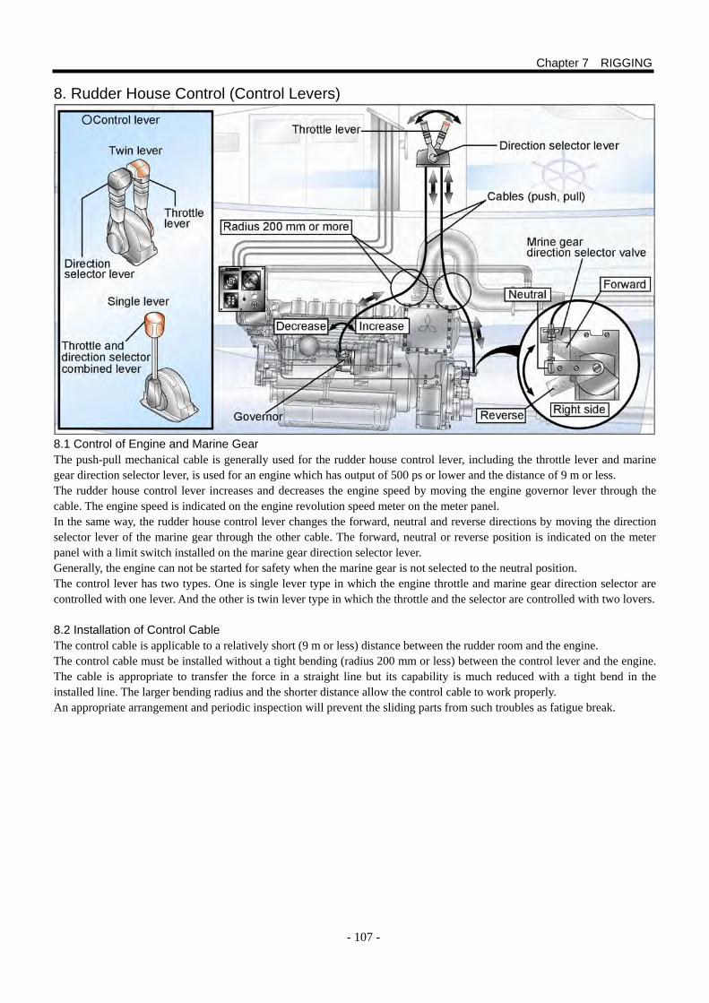
- 107 -
8. Rudder House Control (Control Levers) 8.1 Control of Engine and Marine Gear The push-pull mechanical cable is generally used for the rudder house control lever, including the throttle lever and marine gear direction selector lever, is used for an engine which has output of 500 ps or lower and the distance of 9 m or less. The rudder house control lever increases and decreases the engine speed by moving the engine governor lever through the cable. The engine speed is indicated on the engine revolution speed meter on the meter panel. In the same way, the rudder house control lever changes the forward, neutral and reverse directions by moving the direction selector lever of the marine gear through the other cable. The forward, neutral or reverse position is indicated on the meter panel with a limit switch installed on the marine gear direction selector lever. Generally, the engine can not be started for safety when the marine gear is not selected to the neutral position. The control lever has two types. One is single lever type in which the engine throttle and marine gear direction selector are controlled with one lever. And the other is twin lever type in which the throttle and the selector are controlled with two lovers. 8.2 Installation of Control Cable The control cable is applicable to a relatively short (9 m or less) distance between the rudder room and the engine. The control cable must be installed without a tight bending (radius 200 mm or less) between the control lever and the engine. The cable is appropriate to transfer the force in a straight line but its capability is much reduced with a tight bend in the installed line. The larger bending radius and the shorter distance allow the control cable to work properly. An appropriate arrangement and periodic inspection will prevent the sliding parts from such troubles as fatigue break.
Chapter 7 RIGGING
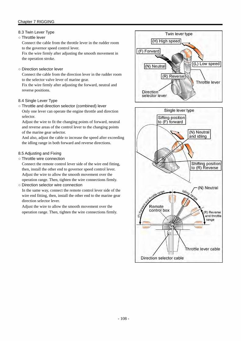
- 108 -
8.3 Twin Lever Type ○ Throttle lever
Connect the cable from the throttle lever in the rudder room to the governor speed control lever. Fix the wire firmly after adjusting the smooth movement in the operation stroke.
○ Direction selector lever
Connect the cable from the direction lever in the rudder room to the selector valve lever of marine gear. Fix the wire firmly after adjusting the forward, neutral and reverse positions.
8.4 Single Lever Type ○ Throttle and direction selector (combined) lever
Only one lever can operate the engine throttle and direction selector. Adjust the wire to fit the changing points of forward, neutral and reverse areas of the control lever to the changing points of the marine gear selector. And also, adjust the cable to increase the speed after exceeding the idling range in both forward and reverse directions.
8.5 Adjusting and Fixing ○ Throttle wire connection
Connect the remote control lever side of the wire end fitting, then, install the other end to governor speed control lever. Adjust the wire to allow the smooth movement over the operation range. Then, tighten the wire connections firmly.
○ Direction selector wire connection In the same way, connect the remote control lever side of the wire end fitting, then, install the other end to the marine gear direction selector lever. Adjust the wire to allow the smooth movement over the operation range. Then, tighten the wire connections firmly.
Chapter 7 RIGGING
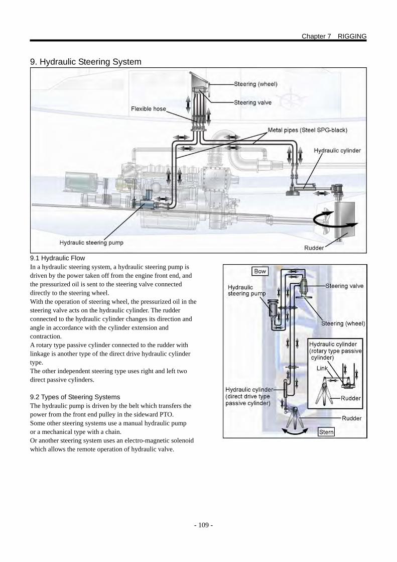
- 109 -
9. Hydraulic Steering System 9.1 Hydraulic Flow In a hydraulic steering system, a hydraulic steering pump is driven by the power taken off from the engine front end, and the pressurized oil is sent to the steering valve connected directly to the steering wheel. With the operation of steering wheel, the pressurized oil in the steering valve acts on the hydraulic cylinder. The rudder connected to the hydraulic cylinder changes its direction and angle in accordance with the cylinder extension and contraction. A rotary type passive cylinder connected to the rudder with linkage is another type of the direct drive hydraulic cylinder type. The other independent steering type uses right and left two direct passive cylinders. 9.2 Types of Steering Systems The hydraulic pump is driven by the belt which transfers the power from the front end pulley in the sideward PTO. Some other steering systems use a manual hydraulic pump or a mechanical type with a chain. Or another steering system uses an electro-magnetic solenoid which allows the remote operation of hydraulic valve.
Chapter 7 RIGGING

- 110 -
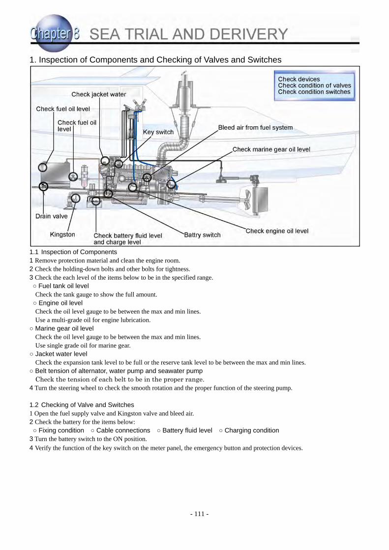
- 111 -
1. Inspection of Components and Checking of Valves and Switches 1.1 Inspection of Components 1 Remove protection material and clean the engine room. 2 Check the holding-down bolts and other bolts for tightness. 3 Check the each level of the items below to be in the specified range. ○ Fuel tank oil level Check the tank gauge to show the full amount. ○ Engine oil level Check the oil level gauge to be between the max and min lines. Use a multi-grade oil for engine lubrication.
○ Marine gear oil level Check the oil level gauge to be between the max and min lines. Use single grade oil for marine gear.
○ Jacket water level Check the expansion tank level to be full or the reserve tank level to be between the max and min lines.
○ Belt tension of alternator, water pump and seawater pump Check the tension of each belt to be in the proper range.
4 Turn the steering wheel to check the smooth rotation and the proper function of the steering pump.
1.2 Checking of Valve and Switches 1 Open the fuel supply valve and Kingston valve and bleed air. 2 Check the battery for the items below: ○ Fixing condition ○ Cable connections ○ Battery fluid level ○ Charging condition
3 Turn the battery switch to the ON position. 4 Verify the function of the key switch on the meter panel, the emergency button and protection devices.
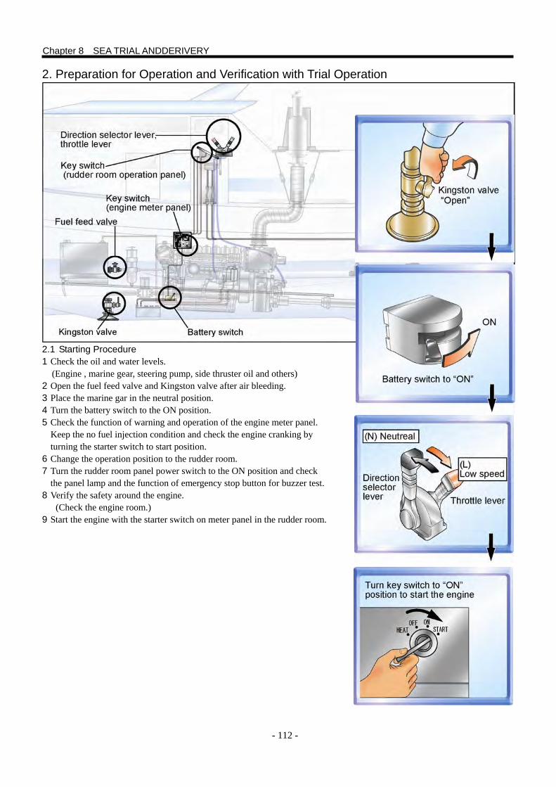
- 112 -
2. Preparation for Operation and Verification with Trial Operation 2.1 Starting Procedure 1 Check the oil and water levels.
(Engine , marine gear, steering pump, side thruster oil and others) 2 Open the fuel feed valve and Kingston valve after air bleeding. 3 Place the marine gar in the neutral position. 4 Turn the battery switch to the ON position. 5 Check the function of warning and operation of the engine meter panel.
Keep the no fuel injection condition and check the engine cranking by turning the starter switch to start position.
6 Change the operation position to the rudder room. 7 Turn the rudder room panel power switch to the ON position and check
the panel lamp and the function of emergency stop button for buzzer test. 8 Verify the safety around the engine.
(Check the engine room.) 9 Start the engine with the starter switch on meter panel in the rudder room.
Chapter 8 SEA TRIAL ANDDERIVERY
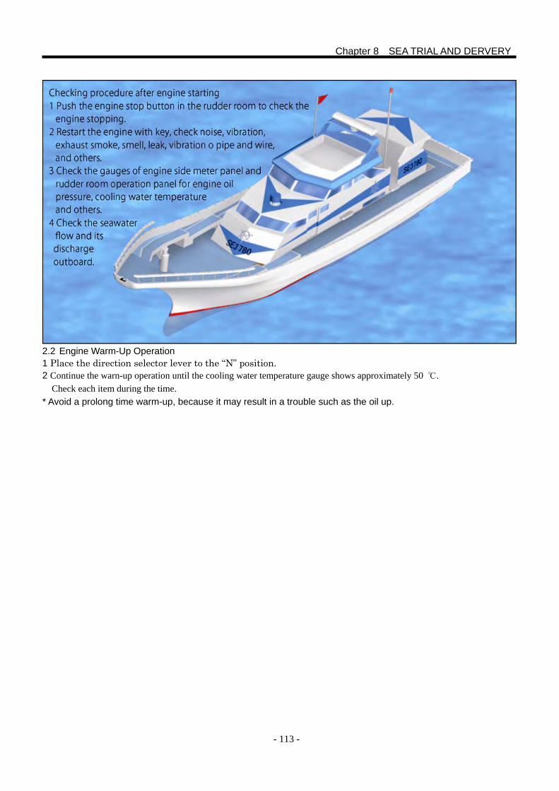
- 113 -
2.2 Engine Warm-Up Operation 1 Place the direction selector lever to the “N” position. 2 Continue the warn-up operation until the cooling water temperature gauge shows approximately 50 ℃.
Check each item during the time. * Avoid a prolong time warm-up, because it may result in a trouble such as the oil up.
Chapter 8 SEA TRIAL AND DERVERY
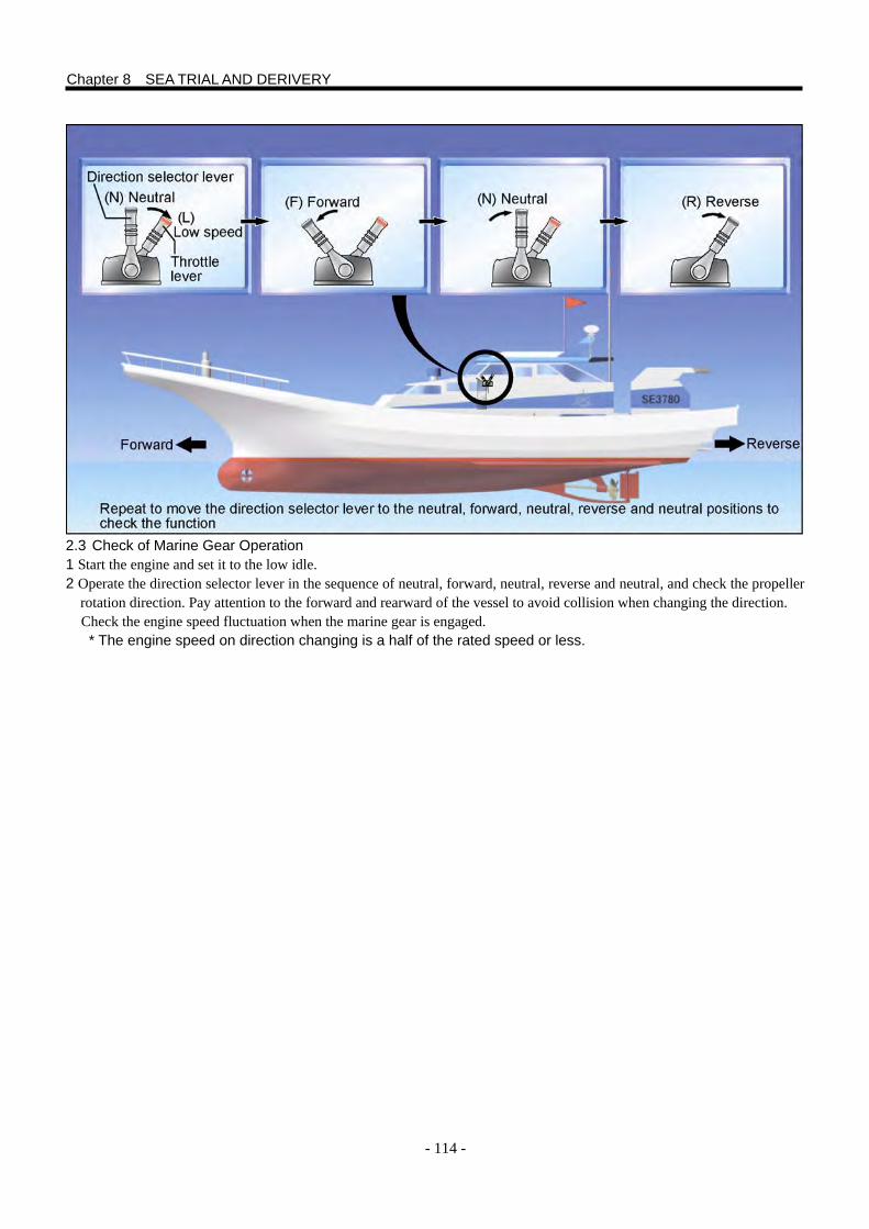
- 114 -
2.3 Check of Marine Gear Operation 1 Start the engine and set it to the low idle. 2 Operate the direction selector lever in the sequence of neutral, forward, neutral, reverse and neutral, and check the propeller
rotation direction. Pay attention to the forward and rearward of the vessel to avoid collision when changing the direction. Check the engine speed fluctuation when the marine gear is engaged. * The engine speed on direction changing is a half of the rated speed or less.
Chapter 8 SEA TRIAL AND DERIVERY
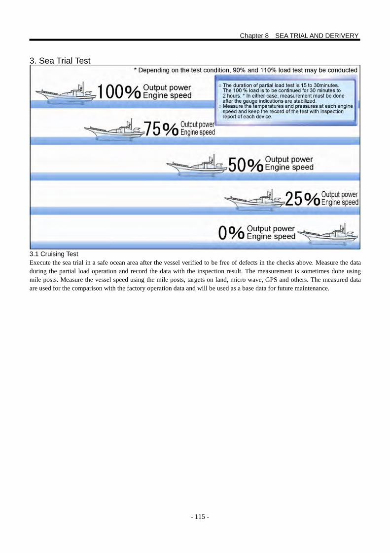
- 115 -
3. Sea Trial Test 3.1 Cruising Test Execute the sea trial in a safe ocean area after the vessel verified to be free of defects in the checks above. Measure the data during the partial load operation and record the data with the inspection result. The measurement is sometimes done using mile posts. Measure the vessel speed using the mile posts, targets on land, micro wave, GPS and others. The measured data are used for the comparison with the factory operation data and will be used as a base data for future maintenance.
Chapter 8 SEA TRIAL AND DERIVERY
- 116 -
4. Delivery and Instruction on Delivery 4.1 Delivery It is important to clarify the specification, take a close contact to the customer, ship builder and equipment manufactures from the time of submission of the drawings by reporting and confirming, in order to satisfy the contract conditions with the customer. It is obviously necessary to verify the performance in the sea trial and complete the all remained defects and modifications. However the delivery is completed only after the explanation about the operation manual, attached documents, service certificate warranty information and after-the-sale service are finished. 4.2 Warranty Information and Service Certificate of the Product The certificate is basically to guarantee the charge-free repair work on the troubles caused by the production responsibility which incurred within the twelve month after the installation of a new engine. As a condition the engine must be subjected to a charge–free inspection within 250 service hours after the delivery based on the service certificate. Also, the use of proper fuel, lubrication oil, and the engine being free from any tampering of seals and modifications affecting the performance are necessary. 4.3 Service Contract The number of customers who extends the intervals of daily maintenance and oil replacement or sometimes skips these items is increasing. The periodic maintenance service contract is recommended to the customers for the use of the engine in the best condition and no trouble. 4.4 Engine Limit Sealing The sealing is applied to limit the maximum speed and power within the range without trouble, provided the handling concerning to the quality and performance of the product is correct. This is a condition of the technical certification. Also the Regulations for Ship Machinery of Ship Safety Law and the Fishing Boat law obligate to install the limit sealing, and the penalty against the violation is also stipulated. The sealing must not be tampered. 4.5 Instruction for Handling the Engine Explain the instructions using the engine and operation manual until the customer understand satisfactory. Especially detailed explanation and real operation practice are necessary when the customer has no experience on the equipment and device. Explain how to use the parts manual and the contents of service certificate (warranty, charge-free inspection, service contact and others). And finally, have the customer’s put signature on the service certificate, and receive the duplicate of the certificate. 4.6 Spare Parts and Tools Always prepare spare parts and tools in the vessel. Check the quantity with the customer referring the list and hand over.
Chapter 8 SEA TRIAL AND DERIVERY


Pub. No. 98CAB-71000Printed in Japan

Pub. N
o. 98CA
B-71000
July2011
ME
DIU
M &
LAR
GE
MA
RIN
E E
NG
INE
INS
TALLA
TION
MA
NU
AL