mechanics of solids (me f211) - bits pilani
TRANSCRIPT

BITS Pilani K K Birla Goa Campus VIKAS CHAUDHARI
MECHANICS OF SOLIDS
(ME F211)

Vikas Chaudhari BITS Pilani, K K Birla Goa Campus
Mechanics of Solids
Chapter-8
Deflections due to Bending

Vikas Chaudhari BITS Pilani, K K Birla Goa Campus
Deflections due to Bending
Contents:
The moment curvature relation
Integration of moment curvature relation
Principle of Superposition
Load- deflection differential equation
Energy methods

Vikas Chaudhari BITS Pilani, K K Birla Goa Campus
Deflections due to Bending
The moment curvature relation
Deformation of an element of a beam subjected to bending moments Mb
The relation between curvature of neutral axis and bending moment is given by E is modulus of elasticity and Izz is moment
of inertia. Longitudinal dimension of the beam will be
in x direction. Bending will take place in xy plane about z
axis. Instead of symbol Izz for moment of inertia,
we use the abbreviation I.
0
1lim b
szz
Md
s ds EI

Vikas Chaudhari BITS Pilani, K K Birla Goa Campus
Deflections due to Bending
The moment curvature relation
Geometry of the neutral axis of a beam bent in the xy plane
Deflection of neutral axis from the knowledge of its curvature Slope of the neutral axis
Differential with arc length s.
tandv
dx
22
2
22
2
sec
cos
d v dx d
dx ds ds
d d v dx
ds dx ds

Vikas Chaudhari BITS Pilani, K K Birla Goa Campus
Deflections due to Bending
The moment curvature relation
Geometry of the neutral axis of a beam bent in the xy plane
From Figure
The curvature is
1 2
2
1cos
1
dx
dsdv dx
2 2
3 22
1
d d v dx
dsdv dx

Vikas Chaudhari BITS Pilani, K K Birla Goa Campus
Deflections due to Bending
The moment curvature relation
Above equation is nonlinear differential equation for determination of
v as a function of x2, if Mb is known.
When the slope angle is small, then dv/dx is small compared to unity
Equation 1 is called moment curvature relation
The term EI is referred as flexural rigidity or bending modulus.
2
2
d d v
ds dx
2 2
3 22
1
b b
zz
M Md d v dx
ds EI EIdv dx
2
2 ------- 1bMd v
dx EI

Vikas Chaudhari BITS Pilani, K K Birla Goa Campus
Deflections due to Bending
Integration of the moment curvature relation
Integration of moment curvature relation leads to the correct
deflection curve.
However suitable boundary conditions should be chosen to determine
the integration constants.
Figure shows the suitable boundary condition encountered in various
supports.

Vikas Chaudhari BITS Pilani, K K Birla Goa Campus
Deflections due to Bending
Problem: The simply supported beam of uniform cross section shown in figure is subjected to a concentrated load W. It is desired to obtained maximum slope and maximum deflection.
L = 3.70m a = b = 1.85m W = 1.8kN E = 11GPa I = 3.33 107mm4

Vikas Chaudhari BITS Pilani, K K Birla Goa Campus
Deflections due to Bending
Solution:
Singularity function method is used to find bending moment.
The maximum deflection is the point at which the slope is zero.
Therefore maximum deflection will be at x = L/2.
Maximum slope will be at x = 0 or at x = L.
Maximum Deflection vmax will be Maximum slope max will be
3
max 25.19
48x L
WLv v mm
EI
2
max
0
0.0042 0.2416
o
x
dv WLrad
dx EI

Vikas Chaudhari BITS Pilani, K K Birla Goa Campus
Deflections due to Bending
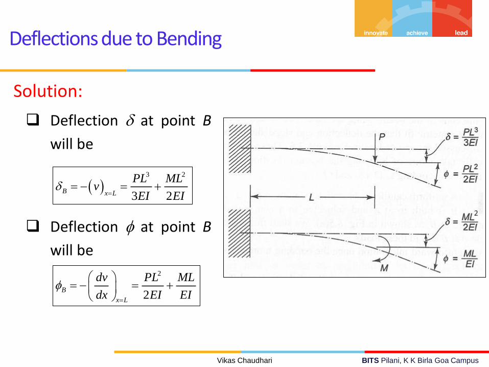
Problem: A uniform cantilever beam has bending modulus EI and length L. It is built in at A and subjected to a concentrated force P and moment M applied at B as shown in figure. Find deflection and slope at point B.
Vikas Chaudhari BITS Pilani, K K Birla Goa Campus
Deflections due to Bending
Solution:
Deflection at point B
will be
Deflection at point B
will be
3 2
3 2B x L
PL MLv
EI EI
2
2B
x L
dv PL ML
dx EI EI

Vikas Chaudhari BITS Pilani, K K Birla Goa Campus
Deflections due to Bending
Superposition
The total deflection is the sum of deflections due to individual
load (Mb)
The deflections in the standard cases are given in table 8.1. The
solution of the original problem then takes the form of a
superposition of these solutions.
Deflection of a beam is linearly proportional to the applied load
The linearity between curvature and deflection is based on
assumption that
Deflections are small
material is linearly elastic

Vikas Chaudhari BITS Pilani, K K Birla Goa Campus
Deflections due to Bending
Problem: The cantilever beam shown in figure carries a concentrated load P and end moment Mo applied at B as shown in figure. Find deflection at point C in terms of the constant bending modulus EI.

Vikas Chaudhari BITS Pilani, K K Birla Goa Campus
Deflections due to Bending
Solution:

Vikas Chaudhari BITS Pilani, K K Birla Goa Campus
Deflections due to Bending
The Load-Deflection Differential Equation
An alternative method to solve beam deflection problem.
The differential equations for force and moment equilibrium are
Therefore,
Using above equation and moment curvature relation, we obtained a single differential equation relating transvers load-intensity function q and transverse deflection v.
0 and 0bdMdVq V
dx dx
2
2
bd Mq
dx
2 2
2 2
d d vEI q
dx dx

Vikas Chaudhari BITS Pilani, K K Birla Goa Campus
Deflections due to Bending
Boundary Conditions
Figure shows the suitable boundary conditions corresponds to four
types of supports.

Vikas Chaudhari BITS Pilani, K K Birla Goa Campus
Deflections due to Bending
Problem
The beam shown in figure is built-in
at A and D and has an offset arm
welded to the beam at the point B
with a load W attached to the arm at
C. It is required to find the deflection
of the beam at the point B.

Vikas Chaudhari BITS Pilani, K K Birla Goa Campus
Deflections due to Bending
Solution
Load intensity
Boundary conditions
Load-deflection differential equation
2 13 3
3
WLq x L W x L
0 and 0 at 0 and dv
v x Ldx
4
4 2 13 3
3
d v LEI W x L x L
dx

Vikas Chaudhari BITS Pilani, K K Birla Goa Campus
Deflections due to Bending
Solution
By integrating previous equation
Boundary conditions gives four integration constants
22
1
1 2 3
33
3 2 2
x Ldv W L xx L c c x c
dx EI
33 2
2
1 2 3 4
33
6 6 6 2
x LW L x xv x L c c c x c
EI
1 2 3 4
8 4; ; 0
27 27c c L c c

Vikas Chaudhari BITS Pilani, K K Birla Goa Campus
Deflections due to Bending
Solution
By inserting boundary conditions in deflection equation
Deflection at point B, by setting x = L/3
2 3 3 29 9 43 3 2
27 2 2 3
Wv L x L x L x Lx
EI
3
3
14
2187B x L
WLv
EI

Vikas Chaudhari BITS Pilani, K K Birla Goa Campus
Deflections due to Bending
Castigliano’s Method to find the deflections Strain energy due to transverse loads
If total elastic energy in a system is expressed in terms of external loads Pi, the corresponding in-line deflections i are given by partial derivatives
2
2 22
2
2
1
2 2
1
2 2
2
xx x
b b
L A
b
L
U dxdydz dxdydzE
M y MU dxdydz dx y dydz
E I EI
MU dx
EI
i
i
U
P

Vikas Chaudhari BITS Pilani, K K Birla Goa Campus
Deflections due to Bending
Castigliano’s Method to find the deflections Important
If, we may wish to know deflection at a point where external
force is zero .
In such case a fictitious force Q is to be considered at that point.
Deflection at that point in the direction of Q is given by U/Q
and setting Q = 0.
Similarly slope is given by U
M

Vikas Chaudhari BITS Pilani, K K Birla Goa Campus
Deflections due to Bending
Castigliano’s Method to find the deflections Simplified equation
Deflection
Slope
0 0
2
2
L L
b b b bi
i i i
M M M MUdx dx
P EI P EI P
0 0
2
2
L L
b b b bi
i i i
M M M MUdx dx
M EI M EI M

Vikas Chaudhari BITS Pilani, K K Birla Goa Campus
Deflections due to Bending
Problem
Using Castigliano’s method, determine the slope and deflection at
point B (loading diagram is shown in figure below).

Vikas Chaudhari BITS Pilani, K K Birla Goa Campus
Deflections due to Bending
Solution
Bending moment = and
Deflection at point B will be
After solving above equation
0 0
2
2
L L
b b b bB
i
M M M MUdx dx
P EI P EI P
bM P L x M bML x
P
3 2
3 2B
PL ML
EI EI

Vikas Chaudhari BITS Pilani, K K Birla Goa Campus
Deflections due to Bending
Solution
Bending moment = and
Slope at point B will be
After solving above equation
bM P L x M 1bM
M
2
2B
PL ML
EI EI
0 0
2
2
L L
b b b bB
M M M MUdx dx
M EI M EI M

Vikas Chaudhari BITS Pilani, K K Birla Goa Campus
Deflections due to Bending
Problem
Using Castigliano’s method, determine the reaction at point A.
Take a = b = L/2

Vikas Chaudhari BITS Pilani, K K Birla Goa Campus
Deflections due to Bending
Solution
We know that deflection at point A is zero. Let’s find reaction at A.
Bending moment = and
Deflection at point A will be
1
b AM R x P x a b
A
Mx
R
0
0
L
b bA
A
M Mdx
EI R
2
0
10 ( )
2
L
A A
LR x Px x dx
EI

Vikas Chaudhari BITS Pilani, K K Birla Goa Campus
Deflections due to Bending
Solution
3
00
03 2 2
L L
A
x L dx LR P x x x
dx
3 350
3 48
AR L PL
5
16AR P

Vikas Chaudhari BITS Pilani, K K Birla Goa Campus
Deflections due to Bending
Problem
Using Castigliano’s method, determine horizontal deflection at point
A (consider deflection due to only bending moments).
313
192A
PL
EI ANS.

Vikas Chaudhari BITS Pilani, K K Birla Goa Campus
Deflections due to Bending
References
1. Introduction to Mechanics of Solids by S. H. Crandall et al
(In SI units), McGraw-Hill