mechanical systems existing conditions evaluation
TRANSCRIPT

Technical Report 3
Mechanical
Mechanical Systems ExistingConditions Evaluation
Author:
Tessa Bauman
technical consultant:
Laura Miller, Ph.D, P.E.
November 11, 2013

Tessa Bauman Twin Rivers Elementary/Intermediate
Contents
Executive Summary 2
Mechanical Systems Summary 3
Mechanical Systems Design Requirements 4
Design Objectives . . . . . . . . . . . . . . . . . . . . . . . . . . . . . . . . . . . . 4
Design Conditions . . . . . . . . . . . . . . . . . . . . . . . . . . . . . . . . . . . 4
Ventilation . . . . . . . . . . . . . . . . . . . . . . . . . . . . . . . . . . . . . . . . 5
Heating and Cooling Loads . . . . . . . . . . . . . . . . . . . . . . . . . . . . . . 7
Annual Energy Consumption & Cost Information . . . . . . . . . . . . . . . . . . 7
Energy Sources 9
Mechanical Operation and Schematics 10
Water Side . . . . . . . . . . . . . . . . . . . . . . . . . . . . . . . . . . . . . . . 10
Air Side . . . . . . . . . . . . . . . . . . . . . . . . . . . . . . . . . . . . . . . . . 12
Major Equipment Schedules . . . . . . . . . . . . . . . . . . . . . . . . . . . . . . 14
Mechanical System Space . . . . . . . . . . . . . . . . . . . . . . . . . . . . . . . 16
LEED Analysis 17
Overall Evaluation 18
References 19
Technical Report 3 Page 1

Tessa Bauman Twin Rivers Elementary/Intermediate
Executive Summary
The purpose of this report is to analyze and give a general overview of the mechanical systems
of Twin Rivers Elementary/Intermediate as they are designed and how they work. It is also
a general theme through out the report to search for interesting solutions for problems that
may arise within the design.
The design was done according to the correct codes and standards. There was no problems
found in comparison to ASHRAE standards 62.1 and 90.1. The building can handle the
appropriate loads. The robust thermal envelope negates loss of energy.
The building is aiming for LEED certification, Silver at the least. The building has many
sustainable features that can influence and inspire the generation that will come to learn
within those walls.
There is a possibility to further extract the site’s energy sources, such as waste heat
recovery, solar accessibility, and wind energy. There is also the acoustic problem that may
come from a glass enclosed mechanical room to consider in future analysis of Twin Rivers.
Technical Report 3 Page 2

Tessa Bauman Twin Rivers Elementary/Intermediate
Mechanical Systems Summary
The Twin Rivers Elementary/Intermediate School will house 800 students of the Mckeesport
Area School District. It is a two story building of 127,000 sq. ft. The Mechanical system
is designed to save 30% of energy when compared to ASHRAE standard 90.1-2007 require-
ments. ASHRAEs Advanced Energy Design Guide for K-12 School Buildings also had a
major impact on the design. The building has many different rooms with different functions,
including the following types of areas:
1. Cafeteria
2. Classroom
3. Computer Lab
4. Corridor
5. Gymnasium
6. Kitchen
7. Library
8. Mechanical & Electrical
9. Nurse’s area
10. Offices
11. Water Closets
The main heating and cooling will come from a geothermal system. This will be an earth
coupled water loop directly connected to water-to-air heat pumps. There will be 2 well fields
located slightly north of the building’s foundation. The earth coupled water loop will also be
connected to a chiller, serving air handling units, variable volume reheat boxes, and radiant
floor systems for the kindergarten, pre-school rooms, and library story room.
The ventilation system consists of 2 dedicated outside air systems (DOAS) which serve
the classrooms and most of the building. The library, cafeteria, gymnasium, and offices each
have individual air handling units (AHU). The library and office AHUs will have zone reheat
coils. The gym and cafeteria AHUs will consist of just a single zone.
Technical Report 3 Page 3

Tessa Bauman Twin Rivers Elementary/Intermediate
Mechanical Systems Design Requirements
Design Objectives
Twin Rivers Elementary/Intermediate was designed to be a state of the art educational
building. It is to be a example for other school districts in the area to follow. LEED
considerations heavily influenced the design. Once completed, the school is to be LEED
Silver certified. The HVAC design references the following standards:ASHRAE 15-2010,62-
2007,90.1-2007, and 55-2004,and uses ASHRAEs 2006 Advanced Energy Design Guide for
K-12 School Building as a guideline.
Design Conditions
Twin Rivers Elementary/Intermediate is in Mckeesport, PA. This is less than 20 miles from
downtown Pittsburgh, PA. This area is mostly a urban area. For this report, weather data
is taken from Pittsburgh. The climate that the school is located in is zone 5A according
to 90.1’s table B-1. Type A is considered to be very humid in the summers, where the
OA needs to be air conditioned to be considered comfortable. Table 1 is the Summer and
Winter outdoor design condtions. This is for degree days 3323 and 5356 respectively. Table
2 demonstrates the necessary design conditions of the indoor air.
Table 1: Design Exterior Temp
Table 2: Design Interior Temp and Relative Humidity
Technical Report 3 Page 4
Tessa Bauman Twin Rivers Elementary/Intermediate
Ventilation
Two DOAS’s, four AHU’s supply the building, one kitchen make-up air unit, and one fan coil
unit provide the building with the appropriate ventilation as required by ASHREA Standard
62.1.
The DOAS’s return air, including that from the restrooms and from the classrooms, is
used within the DOAS for heat recovery. It is then exhausted out of the system near the
outside air intake. Since restroom exhaust is considered a Class 2 exhaust, it is allowed to be
recirculated into the system. The AHU supplying the cafeteria and support area is placed
at least 18 feet away from the kitchen exhaust. This is more than the 15 feet required for a
Class 3 exhaust.
The Kitchen will have specific exhausts to the rooftop. Because of this, there is a kitchen
makeup air unit.
The DOASs will have disposable filters with MERV 13 minimum efficiency minimum as
rated by ASHRAE Test Standard 52-76. The supply filter is upstream of the enthalpy wheel
and the DX cooling coil. There is another filter on the exhaust side of the unit right before
the enthalpy wheel. Both the supply and reactivation air stream shall be completely filtered.
AHU-1,2,3, and 4 will have filters that are UL 900 listed, Class I or Class II. These must be
approved by local authorities.
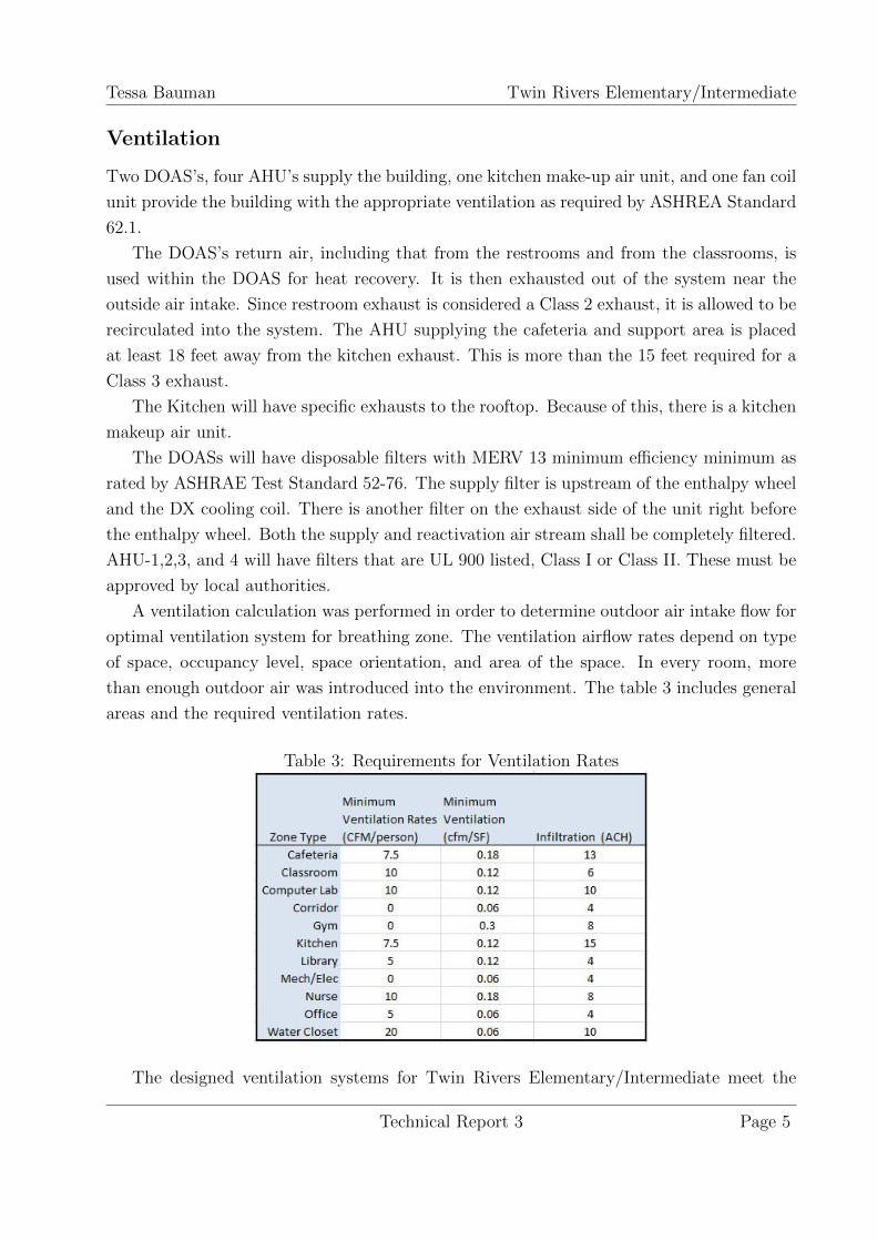
A ventilation calculation was performed in order to determine outdoor air intake flow for
optimal ventilation system for breathing zone. The ventilation airflow rates depend on type
of space, occupancy level, space orientation, and area of the space. In every room, more
than enough outdoor air was introduced into the environment. The table 3 includes general
areas and the required ventilation rates.
Table 3: Requirements for Ventilation Rates
The designed ventilation systems for Twin Rivers Elementary/Intermediate meet the
Technical Report 3 Page 5

Tessa Bauman Twin Rivers Elementary/Intermediate
requirements, as seen in table 4.
Table 4: Required Ventilation Rates vs. Designed Rates
Technical Report 3 Page 6

Tessa Bauman Twin Rivers Elementary/Intermediate
Heating and Cooling Loads
Twin Rivers Elementary/Intermediate is designed for 99.6% winter conditions due to the
lack of occupancy during the summer months. This means that most of the load is for
heating purposes.
A Load simulation was preformed in the TRANE Trace program. To do this, a block
load energy analysis was applied. Similar areas were formed into blocks for the entire school.
for example, a large grouping of classrooms are considered to be one block. Within Trace,
templates for different zone types were created. A block load analysis is for simplicity and
estimation. The mechanical engineers would create a more accurate model. However, The
designer’s load calculation is not available at this time.
The following graph is the load for each month of the year. February has the highest
average load due to extreme winter conditions. December and January do not have a high
load as it may be expected. This is because these months have school holidays that lessen
the load needed during those times. The peak heating load is 10,998 MBh. This is typical
for western Pennsylvania design conditions.
Annual Energy Consumption & Cost Information
Table 5 is the utility summary for the building. The annual cost for electricity and for gas is
almost $50,000. The gas consumption is minimal so the main utility cost is from electricity.
this is a normal estimate for a school building this size.
Technical Report 3 Page 7

Tessa Bauman Twin Rivers Elementary/Intermediate
Table 5: Monthly Utility Costs
Each year $47,985 is paid for utilities. However, the market discount rate decreases the
present value of future payments. If the payment for year 20, the final year of the life cycle
cost analysis, were to be paid today the utility cost would only be $7,133. This is a difference
of $40,852. View table 6 for more details.
Table 6: Annual Utility Costs
Technical Report 3 Page 8

Tessa Bauman Twin Rivers Elementary/Intermediate
Energy Sources
The Building uses available area around the school for a geothermal heat pump system. This
allows for less dependency on other utilities such as gas or electric.
Twin Rivers also uses a grey water system and collects storm water.
Since this is a educational building, the architects decided to tap in to the mechanical
system as a source of knowledge. The main mechanical room’s walls are mainly windows so
that students can educate themselves on the inner workings of the building.
There are a few energy sources that could possible be utilized. Wind turbines were in
earlier designs of this building. There may also be a better solution than the auxiliary boiler.
It may be possible to install a waste heat recovery system, thermal photovoltaic array, or
return to the wind turbine preliminary design.
Technical Report 3 Page 9
Tessa Bauman Twin Rivers Elementary/Intermediate
Mechanical Operation and Schematics
Water Side
Note: Water Temperature Measurement Device missing from diagrams, should be in next
to flow monitoring system after each set of pumps.
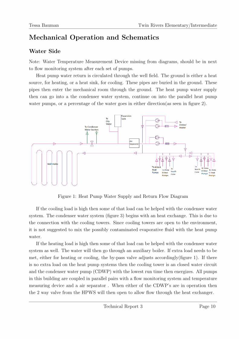
Heat pump water return is circulated through the well field. The ground is either a heat
source, for heating, or a heat sink, for cooling. These pipes are buried in the ground. These
pipes then enter the mechanical room through the ground. The heat pump water supply
then can go into a the condenser water system, continue on into the parallel heat pump
water pumps, or a percentage of the water goes in either direction(as seen in figure 2).
Figure 1: Heat Pump Water Supply and Return Flow Diagram
If the cooling load is high then some of that load can be helped with the condenser water
system. The condenser water system (figure 3) begins with an heat exchange. This is due to
the connection with the cooling towers. Since cooling towers are open to the environment,
it is not suggested to mix the possibly contaminated evaporative fluid with the heat pump
water.
If the heating load is high then some of that load can be helped with the condenser water
system as well. The water will then go through an auxiliary boiler. If extra load needs to be
met, either for heating or cooling, the by-pass valve adjusts accordingly(figure 1). If there
is no extra load on the heat pump systems then the cooling tower is an closed water circuit
and the condenser water pump (CDWP) with the lowest run time then energizes. All pumps
in this building are coupled in parallel pairs with a flow monitoring system and temperature
measuring device and a air separator . When either of the CDWP’s are in operation then
the 2 way valve from the HPWS will then open to allow flow through the heat exchanger.
Technical Report 3 Page 10

Tessa Bauman Twin Rivers Elementary/Intermediate
The condenser water is a solution of 30% poly glycol and the rest water. This is main-
tained through the Glycol Fill Station. If the solution is below 65◦ the boiler is activated
and by-pass valve is shut. If the temperature rises above 90 or drops below 60, an alarm will
sound. The system monitors the flow and temperature after the CDWPs.
Figure 2: Condenser Water Supply and Return Flow Diagram
In figure 2, The HPWS can bypass the Condenser water system. It then goes into an air
separater for equipment safety reasons. Two sets of two parallel water pumps are then in
series. One set of pumps is leading to the heat pump units in the individual rooms.
The room heat pumps are vertical units, like shown in figure 3. these are controlled
by zone thermostats. When the building is in unoccupied mode the unit will only cycle as
necessary to maintain a night time temperature set point.
Figure 3: Typical Room Heat Pump
Technical Report 3 Page 11
Tessa Bauman Twin Rivers Elementary/Intermediate
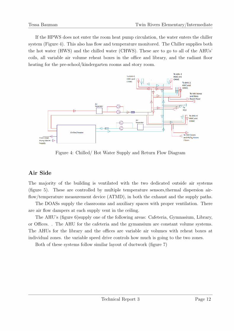
If the HPWS does not enter the room heat pump circulation, the water enters the chiller
system (Figure 4). This also has flow and temperature monitored. The Chiller supplies both
the hot water (HWS) and the chilled water (CHWS). These are to go to all of the AHUs’
coils, all variable air volume reheat boxes in the office and library, and the radiant floor
heating for the pre-school/kindergarten rooms and story room.
Figure 4: Chilled/ Hot Water Supply and Return Flow Diagram
Air Side
The majority of the building is ventilated with the two dedicated outside air systems
(figure 5). These are controlled by multiple temperature sensors,thermal dispersion air-
flow/temperature measurement device (ATMD), in both the exhaust and the supply paths.
The DOASs supply the classrooms and auxiliary spaces with proper ventilation. There
are air flow dampers at each supply vent in the ceiling.
The AHU’s (figure 6)supply one of the following areas: Cafeteria, Gymnasium, Library,
or Offices. . The AHU for the cafeteria and the gymansium are constant volume systems.
The AHUs for the library and the offices are variable air volumes with reheat boxes at
individual zones. the variable speed drive controls how much is going to the two zones.
Both of these systems follow similar layout of ductwork (figure 7)
Technical Report 3 Page 12

Tessa Bauman Twin Rivers Elementary/Intermediate
Figure 5: Typical DOAS Configuration
Figure 6: Typical AHU Configuration
Technical Report 3 Page 13

Tessa Bauman Twin Rivers Elementary/Intermediate
Figure 7: Typical Ventilation: Supply Air and Exhaust Air
Major Equipment Schedules
Table 7: Dedicated Outside Air System Schedule
Table 8: Air Handling Unit Schedule
Technical Report 3 Page 14

Tessa Bauman Twin Rivers Elementary/Intermediate
Table 9: Heat Pump Schedule
Table 10: Chiller/Heater Schedule
Table 11: Heat Exchanger Schedule
Table 12: Evaporative Fluid Cooler Schedule
Table 13: Auxiliary Boiler Schedule
Technical Report 3 Page 15

Tessa Bauman Twin Rivers Elementary/Intermediate
Table 14: Water Pump Schedule
Mechanical System Space
The Mechanical System take 1,282 square feet of usable space. There is a total of 4,437
square feet of both mechanical and electrical space. Some of the mechanical systems pass
through the electrical rooms.
However, since the main mechanical room is being presented educational for the students,
it can be argued that the space is not completely lost to the occupant. The main mechanical
room is viewable through the large curtain walls and LCD monitors are displayed outside of
the room with information about the systems. This feature may possibly cause disruption
if the room is not properly prepared acousticly.
Technical Report 3 Page 16

Tessa Bauman Twin Rivers Elementary/Intermediate
LEED Analysis
The project is projected to get either LEED Silver or Gold certification. The following points
are assumed to be obtained due to MEP systems once construction is completed early 2014.
• Water Use Reduction by 20%
• Grey Water Used for Irrigation
• Optimize energy Performance through geothermal source heat pump and well field
• Minimum IAQ Performance
• Direct-Digital HVAC control system provides optimum thermal comfort
Technical Report 3 Page 17

Tessa Bauman Twin Rivers Elementary/Intermediate
Overall Evaluation
The Twin Rivers Elementary/Intermediate is a well thought out design. This particular type
of HVAC design is becoming popular within the school sector of construction. Geothermal
source heat pump systems seem to be the best system for the environment and also have
a decently short time til the system starts to payback, 3-5 years. In comparison, a solar
thermal system may take anywhere from 7 to 15 years to start paying back. The ventilation
system seems to be efficient due to the lack of occupancy during months at a time. This
allows for the AHU for the offices to run at full capacity but allow other systems to reduce
the output.
Technical Report 3 Page 18

Tessa Bauman Twin Rivers Elementary/Intermediate
References
ASHRAE. Standard 62.1-2007, . Atlanta, GA. American Society of Heating Refrigeration
and Air Conditioning Engineers, Inc
ASHRAE. Stanard 90.1-2007, Atlanta, GA. American Society of Heating Refrigeration
and Air Conditioning Engineers, Inc.
Design by J C Pierce, Architects with help from the following engineering firms
• Phillips & Associates, Inc
• Loftus Engineers
• American Geosciences, Inc.
Technical Report 3 Page 19