mechanical scope for major items bhel and bidder … upload acc.pdf · 4.2 radial bearing and...
TRANSCRIPT

Sl.No Items vendor scope BHEL scope Remarks1
1.1 SRC Tube bundles √2
2.1ACC Steel Structure including steel truss on RCC column
√
2.2 Access Staircase √
2.3 Access Ladder √
2.4 Fan Screens √
2.5Anchorage and concrete embedded steel works
√
2.6 Condensate tank Steel structure √
2.7 Partition windwall between cell √
2.8 support steel structure for risers √
2.9 Windwall around ACC periphery √
2.102.10.1 Primer Paint √
2.10.2 Intermediate Paint √
2.10.3 Final paint √
3
3.1 Fan Stack/Bell √
3.2 Fan √
3.3 Gearbox √
3.4 Motor √
4
4.1Turbine Connection (Welded) incl. Transition piece(Hotbox)
√Terminal point shall be outlet of
Hotbox
4.2 Main Steam Duct (Including Risers) √
4.3 Steam Distribution Manifold √
4.4 Condensate Manifolds √
4.5Steam Balancing Line (from steam duct to Cond. Tank)
√
4.6 Blank Plate (for air tightness test) √
4.7 Expansion bellows √
4.8 Rupture Disc √
4.9 Safety Valve √ if applicable
4.10 Steam Isolating valve (on riser) √
4.11 Bypass Sparger √
4.12 Bypass Valve √
4.13 Vacuum Breaker valve √
4.14 Steam Duct support saddles √
4.15 Concrete duct supports √ Design by bidder
4.16 Embedments for Duct support √
4.17 Corrosion Protection System on Ducting4.17.1 Primer Paint √4.17.2 Intermediate Paint √4.17.3 Final paint √
55.1 Condensate piping
5.1.1From ACC Condensate Collecting lines to Condensate tank
√
5.1.2 From Drain Pot to Condensate Tank √
5.1.3 From Hotbox to Drain Pot √
5.1.4From Condensate Tank to Condensate Pumps √
5.1.5 From Duct to drain pot √5.2 Air Evacuation Piping
5.2.1From ACC Air take off line to Vacuum Equipment
√
5.3 Process Valves
5.3.1 On Condensate piping (if any) √
5.3.2 On Air Extraction piping (if any) √
5.4 Corrosion Protection System on piping5.4.1 Primer Paint √5.4.2 Intermediate Paint √5.4.3 Final paint √
66.1
6.1.1 Condensate Tank √
MECHANICAL SCOPE FOR MAJOR ITEMS BETWEEN BHEL AND BIDDER ANNEXURE‐IV.1‐1
Bundles
Steel Structure
Corrosion Protection System on Steel structure
Fan Drive
Ducting and Ducting auxiliaries
Piping and piping auxiliaries
AuxiliariesTank
Take off price to be included in Price offer
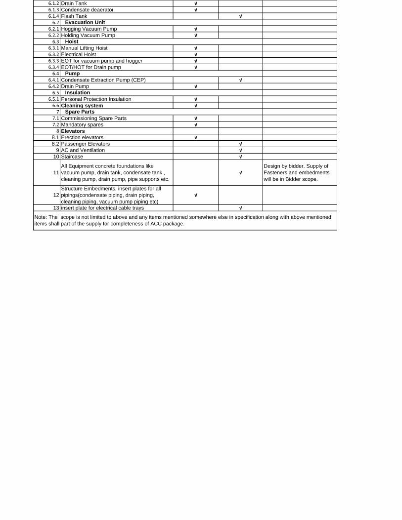
6.1.2 Drain Tank √6.1.3 Condensate deaerator √6.1.4 Flash Tank √6.2
6.2.1 Hogging Vacuum Pump √6.2.2 Holding Vacuum Pump √6.3
6.3.1 Manual Lifting Hoist √6.3.2 Electrical Hoist √6.3.3 EOT for vacuum pump and hogger √6.3.4 EOT/HOT for Drain pump √6.4
6.4.1 Condensate Extraction Pump (CEP) √6.4.2 Drain Pump √6.5
6.5.1 Personal Protection Insulation √6.6 Cleaning system √7
7.1 Commissioning Spare Parts √7.2 Mandatory spares √8 Elevators
8.1 Erection elevators √8.2 Passenger Elevators √
9 AC and Ventilation √10 Staircase √
11All Equipment concrete foundations like vacuum pump, drain tank, condensate tank , cleaning pump, drain pump, pipe supports etc.
√Design by bidder. Supply of Fasteners and embedments will be in Bidder scope.
12Structure Embedments, insert plates for all pipings(condensate piping, drain piping, cleaning piping, vacuum pump piping etc)
√
13 insert plate for electrical cable trays √
Hoist
Pump
Insulation
Note: The scope is not limited to above and any items mentioned somewhere else in specification along with above mentioned items shall part of the supply for completeness of ACC package.
Spare Parts
Evacuation Unit
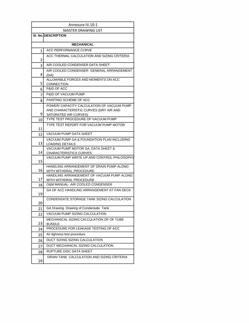
Sl. No. DESCRIPTION
1 ACC PERFORMANCE CURVE
2ACC THERMAL CALCULATION AND SIZING CRITERIA
3 AIR COOLED CONDENSER DATA SHEET
4AIR COOLED CONDENSER- GENERAL ARRANGEMENT (GA)
5ALLOWABLE FORCES AND MOMENTS ON ACC CONNECTION
6 P&ID OF ACC
7 P&ID OF VACUUM PUMP
8 PAINTING SCHEME OF ACC
9
POWER/ CAPACITY CALCULATION OF VACUUM PUMP AND CHARACTERISTIC CURVES (DRY AIR AND SATURATED AIR CURVES)
10 TYPE TEST PROCEDURE OF VACUUM PUMP
11TYPE TEST REPORT FOR VACUUM PUMP MOTOR
12 VACUUM PUMP DATA SHEET
13VACUUM PUMP GA & FOUNDATION PLAN INCLUDING LOADING DETAILS
14VACUUM PUMP MOTOR GA, DATA SHEET & CHARACTERISTICS CURVES
15VACUUM PUMP WRITE UP AND CONTROL PHILOSOPHY
16HANDLING ARRANGEMENT OF DRAIN PUMP ALONG WITH WITHDRAL PROCEDURE
17HANDLING ARRANGEMENT OF VACUUM PUMP ALONG WITH WITHDRAL PROCEDURE
18 O&M MANUAL- AIR COOLED CONDENSER
19GA OF ACC HANDLING ARRANGEMENT AT FAN DECK
20CONDENSATE STORAGE TANK SIZING CALCULATION
21 GA Drawing Drawing of Condensate Tank
22 VACUUM PUMP SIZING CALCULATION
23MECHANICAL SIZING CALCULATION OF OF TUBE BUNDLE
24 PROCEDURE FOR LEAKAGE TESTING OF ACC
25 Air tighness test procedure
26 DUCT SIZING SIZING CALCULATION
27 DUCT MECHANICAL SIZING CALCULATION
28 RUPTURE DISC DATA SHEET
29 DRAIN TANK CALCULATION AND SIZING CRITERIA
Annexure‐IV.10‐1
MASTER DRAWING LIST
MECHANICAL
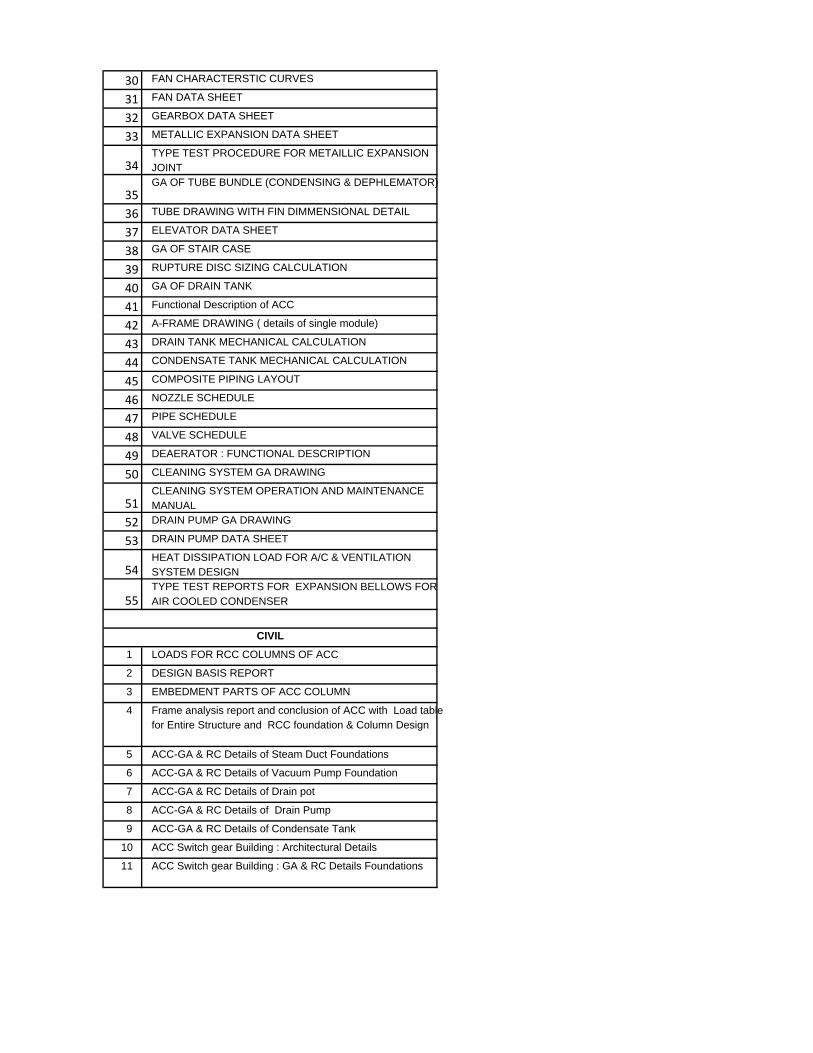
30 FAN CHARACTERSTIC CURVES
31 FAN DATA SHEET
32 GEARBOX DATA SHEET
33 METALLIC EXPANSION DATA SHEET
34TYPE TEST PROCEDURE FOR METAILLIC EXPANSION JOINT
35GA OF TUBE BUNDLE (CONDENSING & DEPHLEMATOR)
36 TUBE DRAWING WITH FIN DIMMENSIONAL DETAIL
37 ELEVATOR DATA SHEET
38 GA OF STAIR CASE
39 RUPTURE DISC SIZING CALCULATION
40 GA OF DRAIN TANK
41 Functional Description of ACC
42 A-FRAME DRAWING ( details of single module)
43 DRAIN TANK MECHANICAL CALCULATION
44 CONDENSATE TANK MECHANICAL CALCULATION
45 COMPOSITE PIPING LAYOUT
46 NOZZLE SCHEDULE
47 PIPE SCHEDULE
48 VALVE SCHEDULE
49 DEAERATOR : FUNCTIONAL DESCRIPTION
50 CLEANING SYSTEM GA DRAWING
51CLEANING SYSTEM OPERATION AND MAINTENANCE MANUAL
52 DRAIN PUMP GA DRAWING
53 DRAIN PUMP DATA SHEET
54HEAT DISSIPATION LOAD FOR A/C & VENTILATION SYSTEM DESIGN
55TYPE TEST REPORTS FOR EXPANSION BELLOWS FOR AIR COOLED CONDENSER
1 LOADS FOR RCC COLUMNS OF ACC
2 DESIGN BASIS REPORT
3 EMBEDMENT PARTS OF ACC COLUMN
4 Frame analysis report and conclusion of ACC with Load table for Entire Structure and RCC foundation & Column Design
5 ACC-GA & RC Details of Steam Duct Foundations
6 ACC-GA & RC Details of Vacuum Pump Foundation
7 ACC-GA & RC Details of Drain pot
8 ACC-GA & RC Details of Drain Pump
9 ACC-GA & RC Details of Condensate Tank
10 ACC Switch gear Building : Architectural Details
11 ACC Switch gear Building : GA & RC Details Foundations
CIVIL
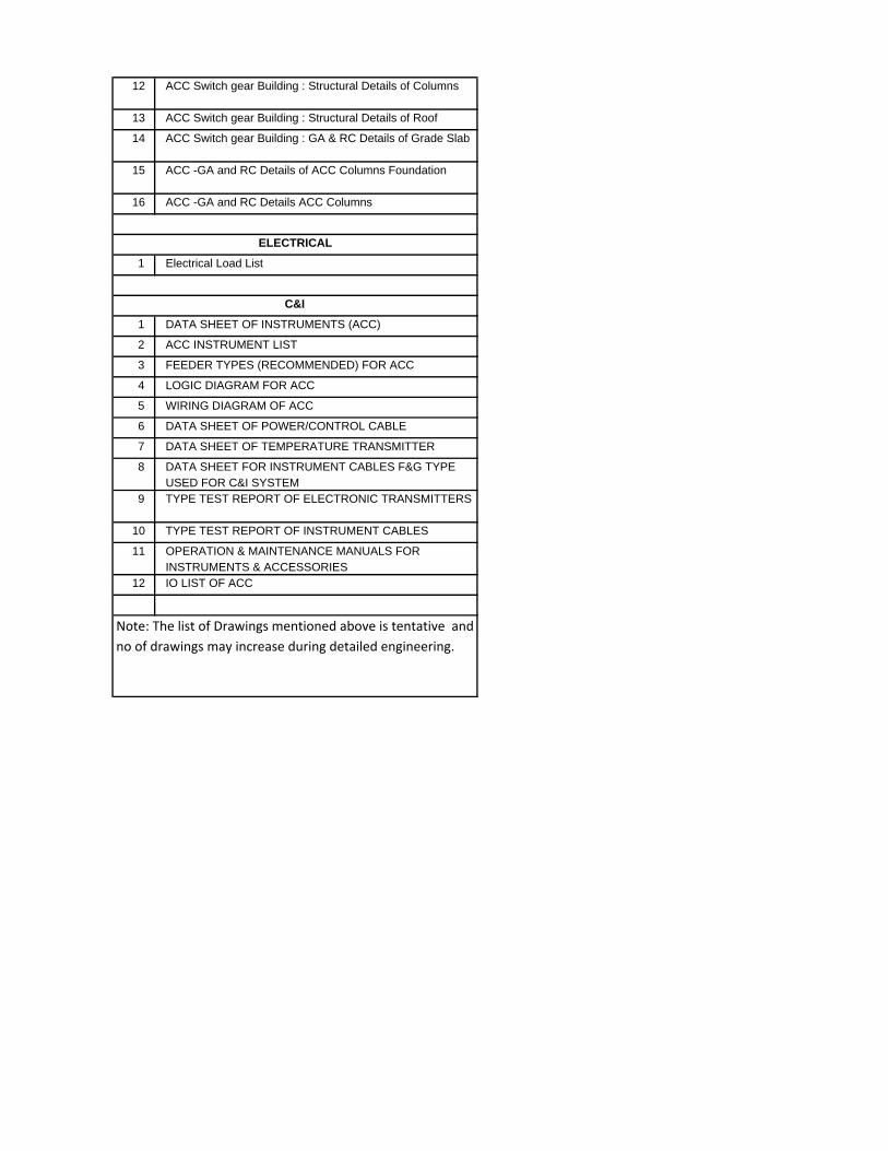
12 ACC Switch gear Building : Structural Details of Columns
13 ACC Switch gear Building : Structural Details of Roof
14 ACC Switch gear Building : GA & RC Details of Grade Slab
15 ACC -GA and RC Details of ACC Columns Foundation
16 ACC -GA and RC Details ACC Columns
1 Electrical Load List
1 DATA SHEET OF INSTRUMENTS (ACC)
2 ACC INSTRUMENT LIST
3 FEEDER TYPES (RECOMMENDED) FOR ACC
4 LOGIC DIAGRAM FOR ACC
5 WIRING DIAGRAM OF ACC
6 DATA SHEET OF POWER/CONTROL CABLE
7 DATA SHEET OF TEMPERATURE TRANSMITTER
8 DATA SHEET FOR INSTRUMENT CABLES F&G TYPE USED FOR C&I SYSTEM
9 TYPE TEST REPORT OF ELECTRONIC TRANSMITTERS
10 TYPE TEST REPORT OF INSTRUMENT CABLES
11 OPERATION & MAINTENANCE MANUALS FOR INSTRUMENTS & ACCESSORIES
12 IO LIST OF ACC
Note: The list of Drawings mentioned above is tentative and
no of drawings may increase during detailed engineering.
C&I
ELECTRICAL
Annexure‐IV.3‐1
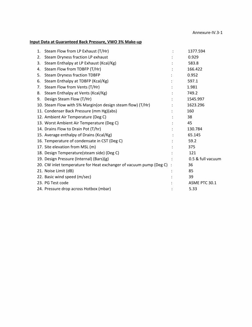
Input Data at Guaranteed Back Pressure, VWO 3% Make‐up
1. Steam Flow from LP Exhaust (T/Hr) : 1377.594
2. Steam Dryness fraction LP exhaust : 0.929
3. Steam Enthalpy at LP Exhaust (Kcal/Kg) : 583.8
4. Steam Flow from TDBFP (T/Hr) : 166.422
5. Steam Dryness fraction TDBFP : 0.952
6. Steam Enthalpy at TDBFP (Kcal/Kg) : 597.1
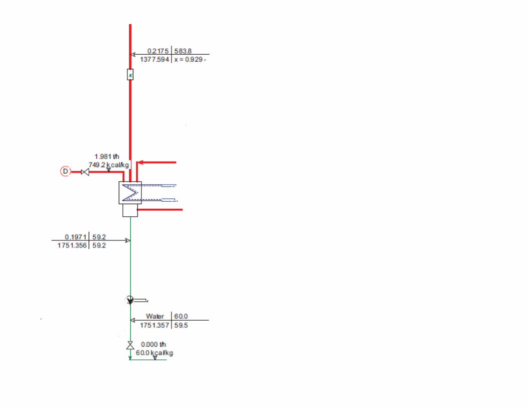
7. Steam Flow from Vents (T/Hr) : 1.981
8. Steam Enthalpy at Vents (Kcal/Kg) : 749.2
9. Design Steam Flow (T/Hr) : 1545.997
10. Steam Flow with 5% Margin(on design steam flow) (T/Hr) : 1623.296
11. Condenser Back Pressure (mm Hg)(abs) : 160
12. Ambient Air Temperature (Deg C) : 38
13. Worst Ambient Air Temperature (Deg C) : 45
14. Drains Flow to Drain Pot (T/hr) : 130.784 15. Average enthalpy of Drains (Kcal/Kg) : 65.145 16. Temperature of condensate in CST (Deg C) : 59.2
17. Site elevation from MSL (m) : 375
18. Design Temperature(steam side) (Deg C) : 121
19. Design Pressure (Internal) (Bars)(g) : 0.5 & full vacuum
20. CW inlet temperature for Heat exchanger of vacuum pump (Deg C) : 36
21. Noise Limit (dB) : 85
22. Basic wind speed (m/sec) : 39
23. PG Test code : ASME PTC 30.1
24. Pressure drop across Hotbox (mbar) : 5.33

List of Mandatory Spares for Air Cooled Condenser-3X800MW PATRATU STPS EXPANSION PHASE-ISl. No. Description Quantity Remarks
1
Main Turbine condenser vacuum pump complete assembly
including complete coupling 1 No
2 Tube Nest assembly of vacuum pump cooler 1 No
3Complete fan assembly (including
shafts,blades,bearings,hub,couplings,support etc)5 fan assemblies
4 Vacuum Pump for main turbine condenser
4.1
complete rotating assembly with impeller,rotor,shaft and
coupling 1 No
4.2 Radial Bearing and Thrust Bearing
1 set ( Requirement for one
pump)
4.3 Complete set of soft parts like gaskets,o‐rings etc. for cooler
2 sets (Requirement for two
pump)
4.5 Vacuum Pump motor 1 No
5 Measuring Instruments
5.1 Electronic Transmitters
5.1.1
Transmitters of all type,range and model no. (for
measurement of pressure, differential pressure
flow,level,vibration etc.)
10% or minimum 1 No.
whichever is more
1 pressure transmitter
2 Differential pressure transmitter
3 level transmitter
4 vibration transmitters
6
Interface modules at field ( between field transmitters &
DDCMIS) like Zener barrier,power supply isolator,isolator (as
applicable)etc. 10% of each type
7 Temperature elements
7.1 RTD's
10% of each type and length
or minimum 1 no whichever is
more
7.2 Thermocouples
10% of each type and length
or minimum 1 no whichever is
more
7.3 Thermowell for above application
10% of each type and length
or minimum 1 no whichever is
more
7.4 Temperature transmitters
10% or minimum 2 nos
whichever is more
8 Pneumatic control valve actuator assembly
10% or 1 Nos of each
type,model and
rating,whichever is more
9 Low Pressure piping
9.1 valve all sizes (population= all Units) 5% of the total population of
each type, size and class or
minimum 2 nos. of each type,
size & class whichever is more.
Note: 1) if there is one no valve
only of particular type, class and
size then only one no is required.
2) wherever valves are specified as
mandatory spares, complete valve
along with actuator and all other
accessories which are the part of
original supply shall also be
supplied.
Note:
The quantity column in the Mandatory spare list is for all three units. The quantity to be w orked out as follows:
1) Wherev er quantity has been specified as percentage (%), it shall mean percentage (%) of the total population of the item in the station
(project), unless specified otherwise and the fraction will be rounded off to the next higher whole number.
2) Where it is specified as "set" . it would mean the requirement for the single equipment/system and to be multiplied with total no. of such
equipment / system in the project to arrive at the quantity.
3) Wherever "set" is specified it would mean total number in one such equipment/system and shall be considered as quantity.
4) Wherever the quantities have been indicated for each type, size, thickness, material, radius, range etc. these shall cover all the items
supplied and installed and the break up for these shall be furnished in the bid.

MECHANICAL
Sl. No. Clause no. Check Point YES/ No Remarks
1 I.1 Confirmation of Scope of proposal
2 I.1 Ensured Additional requirements
3 I.1 Confirmation for supervision of Erection and Commissioning of ACC package.
4 II Confirmation that all project site details has been referred and sufficient.
5 III All requirements of funtional Guarantees are accepted?
6
III.1.2 a‐I and Annexure‐
IV.3‐1
ACC should be designed for guaranteed back pressure of 160 mmHg (abs) (parameters as per
annexure IV.3‐1) with 5% margin on design steam flow measured at 300 mm downstream of Ist
welding joint of turbine exhaust at Hotbox at valve wide open (VWO), 3 % make‐up (MU)
Condition considering pressure drop in Hot Box / ETD as per clause IV.3.5.
7 III.1.2 a‐ii
Unit Power Consumption of all unit auxiliaries shall be measured at motor terminal end as per
clause . Power meter for this shall be provided at the time of measurement during PG Test.
Vendor to confirm.
8 III.1.2 c) i Confirmation that Method for measurement of Noise as per specification
9 III.1.2 c) Category ‐3 test shall be carried out as per clause.
10 III.2
Value of Guaranteed Aux.liary Power Consumption at 160mm Hg condenser pressure is provided
along with the price bid.
11 III.2 Bidder shall provide suitable power meter for auxilairy power measurement
12 III.2.1 Confirmation that Condenser back pressure Acceptance test as per ASME PTC 30.1
13
IV.1 and Annexure‐IV.1‐
1 Signed and stamped copy of Annexure‐IV.1‐1 furnished.
14
Sl. No. 5.1.3 of
Annexure‐IV.1‐1
Piping from Hot Box to drain pot with all support and its structure as per of BHEL specification is in
vendor’s scope. Bidder to include the same and confirm.
15 IV.3.1
Pressure Drop across Hot Box considered 5.33 mbar and Confirmation that Design shall meet
requirments of HEI
16 IV.3.2
Thermal calculation for required area as per HEI and the total pressure drop with calculation is
furnished with bid.
17 IV.3.3 Frequency range of equipments shall be 47.5Hz to 51.5 Hz
18 IV.3.4
Guaranteed back pressure and guaranteed Auxiliary power consumption conditions shallconform to input Data/ Design data as per ANNEXURE-IV.3-1.
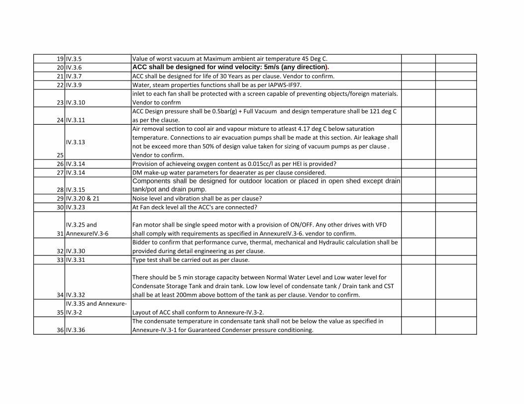
19 IV.3.5 Value of worst vacuum at Maximum ambient air temperature 45 Deg C.
20 IV.3.6 ACC shall be designed for wind velocity: 5m/s (any direction). 21 IV.3.7 ACC shall be designed for life of 30 Years as per clause. Vendor to confirm.
22 IV.3.9 Water, steam properties functions shall be as per IAPWS‐IF97.
23 IV.3.10
inlet to each fan shall be protected with a screen capable of preventing objects/foreign materials.
Vendor to confrm
24 IV.3.11
ACC Design pressure shall be 0.5bar(g) + Full Vacuum and design temperature shall be 121 deg C
as per the clause.
25
IV.3.13
Air removal section to cool air and vapour mixture to atleast 4.17 deg C below saturation
temperature. Connections to air evacuation pumps shall be made at this section. Air leakage shall
not be exceed more than 50% of design value taken for sizing of vacuum pumps as per clause .
Vendor to confirm.
26 IV.3.14 Provision of achieveing oxygen content as 0.015cc/l as per HEI is provided?
27 IV.3.14 DM make‐up water parameters for deaerater as per clause considered.
28 IV.3.15
Components shall be designed for outdoor location or placed in open shed except draintank/pot and drain pump.
29 IV.3.20 & 21 Noise level and vibration shall be as per clause?
30 IV.3.23 At Fan deck level all the ACC's are connected?
31
IV.3.25 and
AnnexureIV.3‐6
Fan motor shall be single speed motor with a provision of ON/OFF. Any other drives with VFD
shall comply with requirements as specified in AnnexureIV.3‐6. vendor to confirm.
32 IV.3.30
Bidder to confirm that performance curve, thermal, mechanical and Hydraulic calculation shall be
provided during detail engineering as per clause.
33 IV.3.31 Type test shall be carried out as per clause.
34 IV.3.32
There should be 5 min storage capacity between Normal Water Level and Low water level for
Condensate Storage Tank and drain tank. Low low level of condensate tank / Drain tank and CST
shall be at least 200mm above bottom of the tank as per clause. Vendor to confirm.
35
IV.3.35 and Annexure‐
IV.3‐2 Layout of ACC shall conform to Annexure‐IV.3‐2.
36 IV.3.36
The condensate temperature in condensate tank shall not be below the value as specified in
Annexure‐IV.3‐1 for Guaranteed Condenser pressure conditioning.
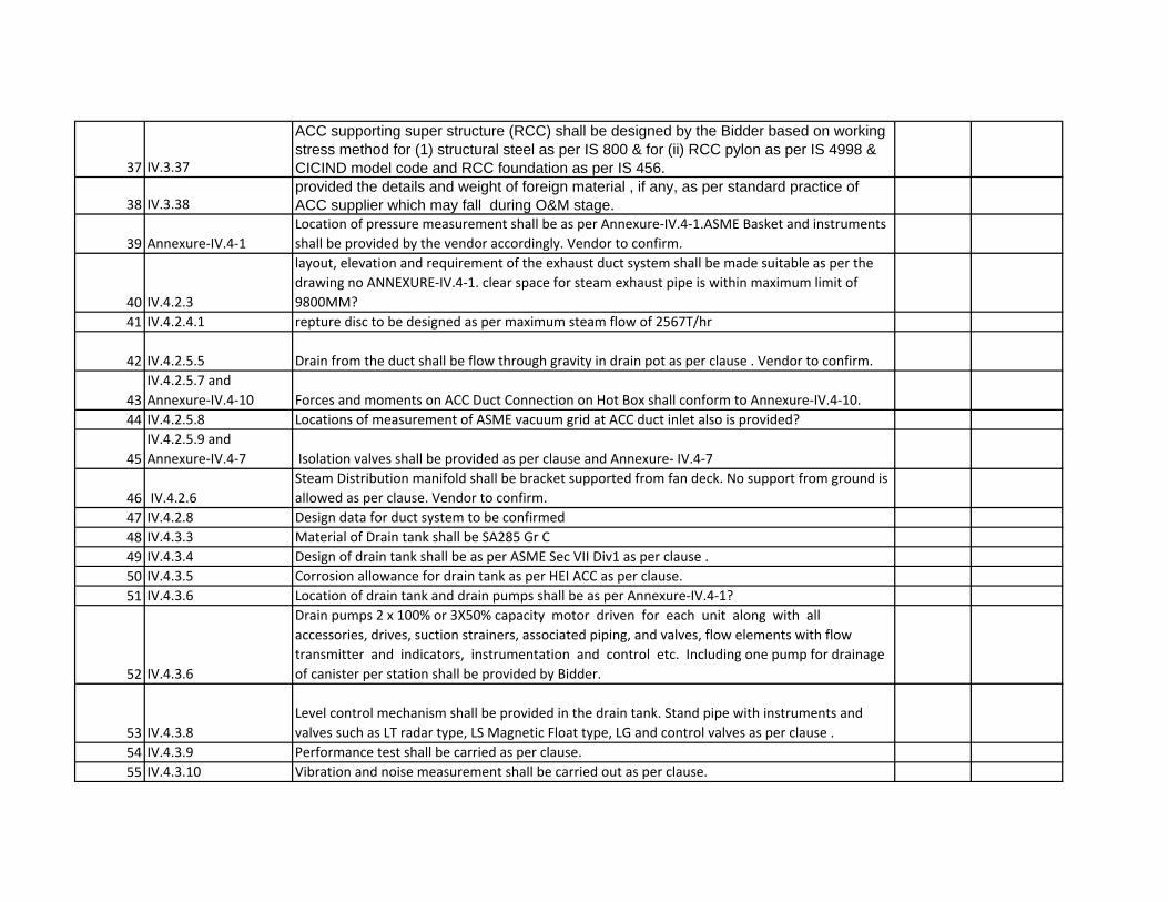
37 IV.3.37
ACC supporting super structure (RCC) shall be designed by the Bidder based on working stress method for (1) structural steel as per IS 800 & for (ii) RCC pylon as per IS 4998 & CICIND model code and RCC foundation as per IS 456.
38 IV.3.38provided the details and weight of foreign material , if any, as per standard practice of ACC supplier which may fall during O&M stage.
39 Annexure‐IV.4‐1
Location of pressure measurement shall be as per Annexure‐IV.4‐1.ASME Basket and instruments
shall be provided by the vendor accordingly. Vendor to confirm.
40 IV.4.2.3
layout, elevation and requirement of the exhaust duct system shall be made suitable as per the
drawing no ANNEXURE‐IV.4‐1. clear space for steam exhaust pipe is within maximum limit of
9800MM?
41 IV.4.2.4.1 repture disc to be designed as per maximum steam flow of 2567T/hr
42 IV.4.2.5.5 Drain from the duct shall be flow through gravity in drain pot as per clause . Vendor to confirm.
43
IV.4.2.5.7 and
Annexure‐IV.4‐10 Forces and moments on ACC Duct Connection on Hot Box shall conform to Annexure‐IV.4‐10.
44 IV.4.2.5.8 Locations of measurement of ASME vacuum grid at ACC duct inlet also is provided?
45
IV.4.2.5.9 and
Annexure‐IV.4‐7 Isolation valves shall be provided as per clause and Annexure‐ IV.4‐7
46 IV.4.2.6
Steam Distribution manifold shall be bracket supported from fan deck. No support from ground is
allowed as per clause. Vendor to confirm.
47 IV.4.2.8 Design data for duct system to be confirmed
48 IV.4.3.3 Material of Drain tank shall be SA285 Gr C
49 IV.4.3.4 Design of drain tank shall be as per ASME Sec VII Div1 as per clause .
50 IV.4.3.5 Corrosion allowance for drain tank as per HEI ACC as per clause.
51 IV.4.3.6 Location of drain tank and drain pumps shall be as per Annexure‐IV.4‐1?
52 IV.4.3.6
Drain pumps 2 x 100% or 3X50% capacity motor driven for each unit along with all
accessories, drives, suction strainers, associated piping, and valves, flow elements with flow
transmitter and indicators, instrumentation and control etc. Including one pump for drainage
of canister per station shall be provided by Bidder.
53 IV.4.3.8
Level control mechanism shall be provided in the drain tank. Stand pipe with instruments and
valves such as LT radar type, LS Magnetic Float type, LG and control valves as per clause .
54 IV.4.3.9 Performance test shall be carried as per clause.
55 IV.4.3.10 Vibration and noise measurement shall be carried out as per clause.
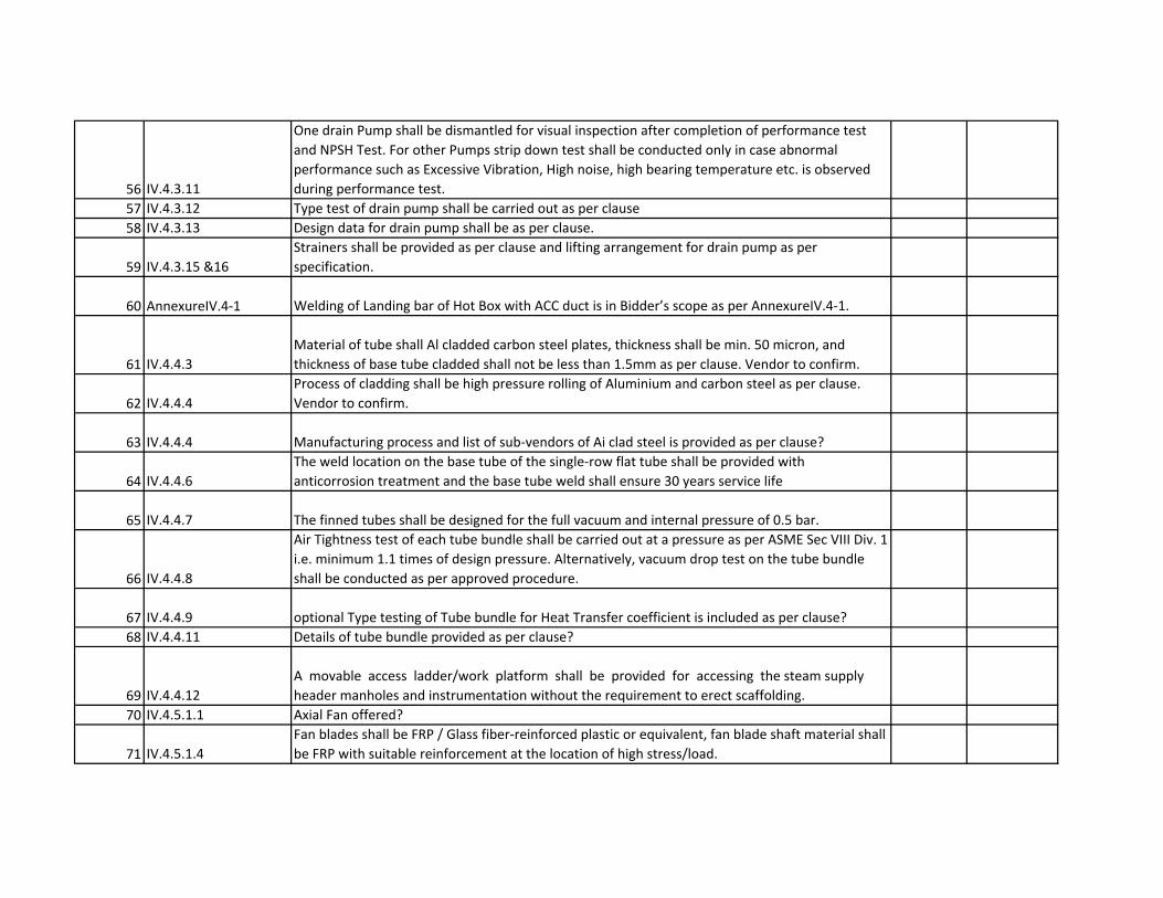
56 IV.4.3.11
One drain Pump shall be dismantled for visual inspection after completion of performance test
and NPSH Test. For other Pumps strip down test shall be conducted only in case abnormal
performance such as Excessive Vibration, High noise, high bearing temperature etc. is observed
during performance test.
57 IV.4.3.12 Type test of drain pump shall be carried out as per clause
58 IV.4.3.13 Design data for drain pump shall be as per clause.
59 IV.4.3.15 &16
Strainers shall be provided as per clause and lifting arrangement for drain pump as per
specification.
60 AnnexureIV.4‐1 Welding of Landing bar of Hot Box with ACC duct is in Bidder’s scope as per AnnexureIV.4‐1.
61 IV.4.4.3
Material of tube shall Al cladded carbon steel plates, thickness shall be min. 50 micron, and
thickness of base tube cladded shall not be less than 1.5mm as per clause. Vendor to confirm.
62 IV.4.4.4
Process of cladding shall be high pressure rolling of Aluminium and carbon steel as per clause.
Vendor to confirm.
63 IV.4.4.4 Manufacturing process and list of sub‐vendors of Ai clad steel is provided as per clause?
64 IV.4.4.6
The weld location on the base tube of the single‐row flat tube shall be provided with
anticorrosion treatment and the base tube weld shall ensure 30 years service life
65 IV.4.4.7 The finned tubes shall be designed for the full vacuum and internal pressure of 0.5 bar.
66 IV.4.4.8
Air Tightness test of each tube bundle shall be carried out at a pressure as per ASME Sec VIII Div. 1
i.e. minimum 1.1 times of design pressure. Alternatively, vacuum drop test on the tube bundle
shall be conducted as per approved procedure.
67 IV.4.4.9 optional Type testing of Tube bundle for Heat Transfer coefficient is included as per clause?
68 IV.4.4.11 Details of tube bundle provided as per clause?
69 IV.4.4.12
A movable access ladder/work platform shall be provided for accessing the steam supply
header manholes and instrumentation without the requirement to erect scaffolding.
70 IV.4.5.1.1 Axial Fan offered?
71 IV.4.5.1.4
Fan blades shall be FRP / Glass fiber‐reinforced plastic or equivalent, fan blade shaft material shall
be FRP with suitable reinforcement at the location of high stress/load.

72 IV.4.5.1.4
The bolts, nuts and washers for fixing of the fan blades on the hub shall be 1401 SAE grade or SS
A2 or equivalent or with higher grade and coupling piece shall be Aluminum.
73 IV.4.5.1.4
The fan hub material shall be carbon steel Hot dip galvanized or painted, the hub flange shall be
steel with polyurethane coating or galvanized, bushing and seal ring (if applicable) shall be as per
standard practice of Bidder and the bolts, nuts and washer for hub flange shall be steel grade 8.8
with galvanizing.
74 IV.4.5.1.4
The angle of fan blade shall be adjustable at standstill. Fan blade and hub assemblies shall be
designed to facilitate adjustment of blade pitch following installation and operation in the ACC.
Special tool for Fan blade fastening to be provided.
75 IV.4.5.1.7
Record of fan blade and hub assemblies must be maintained and communicated with theshipment of separate fan blades and hubs. Replacement fan blades shall bemanufactured in such a fashion as to be interchangeable, without adverse impacts tostatic balancing. the blades of fans shall be made in such a way that either all bladesor blades in pair shall be interchangeable with each other.
76 IV.4.5.1.8
Fan blade systems and operations will be designed so that there are no naturalfrequencies set up between the intended operations of the fans and the ACC structureitself.
77 IV.4.5.1.9 Fans shall be capable of operating at 110% of their design operating speeds.
78 IV.4.5.1.10
The inlet fan rings/ fan bells shall be fabricated from multi-segmented FRP and as perclause
79 IV.4.5.1.17
The fan blade shall be statically balanced in accordance with DIN ISO 1940 to meet thebalancing grade G 6.3.
80 IV.4.5.1.18
The fan hub shall be dynamically balanced at speeds at least equal to operating speed or statically balanced in accordance with DIN ISO 1940 to meet balancing grade G 6.3.
81 IV.4.5.1.20
optional Type test of Fan using scaled down model or full size model (applicable for theproject) for performance, noise and vibration at full speed, 110%, 75%, 50% and 25%speed shall be conducted as per procedure. The test of Fan shall be witnessed by BHEL
82 IV.4.5.1.21
performance test (including flow, pressure, noise, vibration & alignment etc.) offan/compressor as applicable shall be tested at site.
83 IV.4.5.2.1 Type of gear is Vertical shaft helical gear type with service facor as per clause?84 IV.4.5.2.2 Gearbox shall be designed as per AGMA.

85 IV.4.5.2.3
Gearbox and bearing (both sides) to operate for 100,000 hours before major repair orreplacement as per clause.
86 IV.4.5.2.5 The lube oil pump shall be provided as per clause.
87 IV.4.5.2.8
The gear box housing shall have provision for mounting of flanged mounted motor as perclause.
88 IV.4.5.2.15
Gear box shall have fan vibration switch measurement device and SPM nipple for localvibration measurement.
89 IV.4.5.2.16
Gear box shall have Dust proof breather filter, low oil level switch, Lube oil sight glass,Lube oil drain cock with drain hose connection, Fan reverse rotation backstop, Double oilshaft seals and dipstick assembly for oil level monitoring
90 IV.4.5.2.17
The transmission efficiency of the gearbox shall not be lower than 97%. The design life of gearbox
under the condition of full load and total speed shall not be less than 100,000 hours and the
gearbox shall use anti‐friction bearing with metal shield
91 IV.4.5.2.18 Performance testing of first gear box as per clause and its procedure?
92 IV.4.6.2
The condensate tank shall be mounted on a steel structure on higher elevation. The elevation of CST shall be suitably kept (approx. 15 M) in order to accommodateCEP’s. Also, the supporting structure for CST to be designed inline with Annexure-IV.3-2 of specification.
93 IV.4.6.3
Material of Condensate storage tank (CST)is specified as per Clause? (SA285GrC orequivalent)
94 IV.4.6.4 Condensate tank shall be designed as per ASME Sec VIII, Div1.95 IV.4.6.5 Corrosion allowance on CST is specified as per HEI?
96 IV.4.6.6
Bidder to provide all galleries, crawl beams, all around platforms, handrails, staircasenecessary for safe and efficient access to condensate storage tank for erection, operationand maintenance.
97 IV.4.6.7
Stand pipes with necessary instruments with water level gauges and isolation valves shallbe provided for condensate storage tank.
98 IV.4.6.8
Maximum oxygen content of condensate at the outlet of condensate storage tank shall be0.015 cc/litre as per HEI. To achieve the same proper deareation system for make-upwater and condensate shall be provided.
99 IV.4.6.9 Anti vortex baffling is provided at connections of suction of CEP?100 IV.4.7.1 Piping and fittings shall be as per ASME/ANSI B 31.1. 101 Annexure IV.4‐7 Material of Pipe and fittings shall be as per Annexure IV.4-7?102 Annexure IV.4‐7 Material of Valves shall be per Annexure IV.4-7?
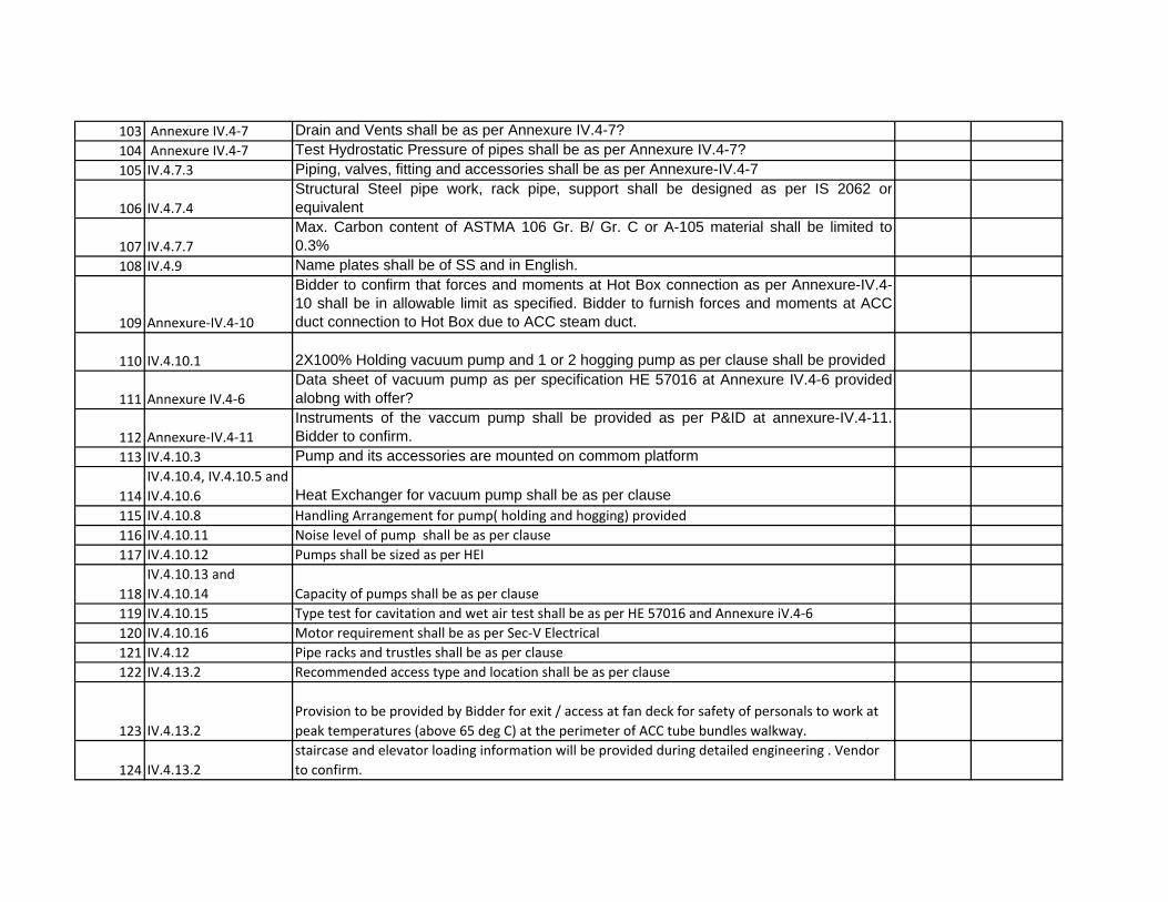
103 Annexure IV.4‐7 Drain and Vents shall be as per Annexure IV.4-7?104 Annexure IV.4‐7 Test Hydrostatic Pressure of pipes shall be as per Annexure IV.4-7?105 IV.4.7.3 Piping, valves, fitting and accessories shall be as per Annexure-IV.4-7
106 IV.4.7.4
Structural Steel pipe work, rack pipe, support shall be designed as per IS 2062 orequivalent
107 IV.4.7.7
Max. Carbon content of ASTMA 106 Gr. B/ Gr. C or A-105 material shall be limited to0.3%
108 IV.4.9 Name plates shall be of SS and in English.
109 Annexure‐IV.4‐10
Bidder to confirm that forces and moments at Hot Box connection as per Annexure-IV.4-10 shall be in allowable limit as specified. Bidder to furnish forces and moments at ACCduct connection to Hot Box due to ACC steam duct.
110 IV.4.10.1 2X100% Holding vacuum pump and 1 or 2 hogging pump as per clause shall be provided
111 Annexure IV.4‐6
Data sheet of vacuum pump as per specification HE 57016 at Annexure IV.4-6 providedalobng with offer?
112 Annexure‐IV.4‐11
Instruments of the vaccum pump shall be provided as per P&ID at annexure-IV.4-11.Bidder to confirm.
113 IV.4.10.3 Pump and its accessories are mounted on commom platform
114
IV.4.10.4, IV.4.10.5 and
IV.4.10.6 Heat Exchanger for vacuum pump shall be as per clause115 IV.4.10.8 Handling Arrangement for pump( holding and hogging) provided
116 IV.4.10.11 Noise level of pump shall be as per clause
117 IV.4.10.12 Pumps shall be sized as per HEI
118
IV.4.10.13 and
IV.4.10.14 Capacity of pumps shall be as per clause
119 IV.4.10.15 Type test for cavitation and wet air test shall be as per HE 57016 and Annexure iV.4‐6
120 IV.4.10.16 Motor requirement shall be as per Sec‐V Electrical
121 IV.4.12 Pipe racks and trustles shall be as per clause
122 IV.4.13.2 Recommended access type and location shall be as per clause
123 IV.4.13.2
Provision to be provided by Bidder for exit / access at fan deck for safety of personals to work at
peak temperatures (above 65 deg C) at the perimeter of ACC tube bundles walkway.
124 IV.4.13.2
staircase and elevator loading information will be provided during detailed engineering . Vendor
to confirm.
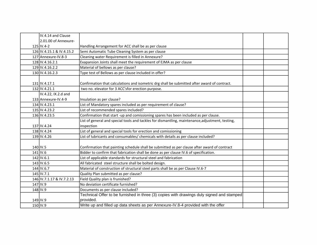
125
IV.4.14 and Clause
2.01.00 of Annexure‐
IV.4‐2 Handling Arrangement for ACC shall be as per clause
126 IV.4.15.1 & IV.4.15.2 Semi Automatic Tube Cleaning System as per clause
127 Annexure‐IV.8‐3 Cleaning water Requirement is filled in Annexure?
128 IV.4.16.2.1 Exapansion Joints shall meet the requirement of EJMA as per clause
129 IV.4.16.2.2 Material of bellows as per clause?
130 IV.4.16.2.3 Type test of Bellows as per clause included in offer?
131 IV.4.17.1 Confirmation that calculations and isometric drg shall be submitted after award of contract.
132 IV.4.21.1 two no. elevator for 3 ACC'sfor erection purpose.
133
IV.4.22, IX.2.d and
Annexure‐IV.4‐9 Insulation as per clause?
134 IV.4.23.1 List of Mandatory spares included as per requirement of clause?
135 IV.4.23.2 List of recommended spares included?
136 IV.4.23.5 Confirmation that start ‐up and comissioning spares has been included as per clause.
137 IV.4.24
List of general and special tools and tackles for dismantling, maintenance,adjustment, testing,
inspection
138 IV.4.24 List of general and special tools for erection and comissioning
139 IV.4.26 List of lubricants and consumables/ chemicals with details as per clause included?
140 IV.5 Confirmation that painting schedule shall be submitted as per clause after award of contract
141 IV.6 Bidder to confirm that fabrication shall be done as per clause IV.6 of specification.
142 IV.6.1 List of applicable standards for structural steel and fabrication
143 IV.6.5 All fabricated steel structure shall be bolted design.
144 IV.6.7 Material of construction of structural steel parts shall be as per Clause IV.6‐7
145 IV.7.1 Quality Plan submitted as per clause?
146 IV.7.1.17 & IV.7.2.13 Field Quality plan is frunished?
147 IV.9 No deviation certificate furnished?
148 IV.9 Documents as per clause included?
149 IV.9
Technical Offer to be furnished in three (3) copies with drawings duly signed and stampedprovided.
150 IV.9 Write up and filled up data sheets as per Annexure-IV.8-4 provided with the offer
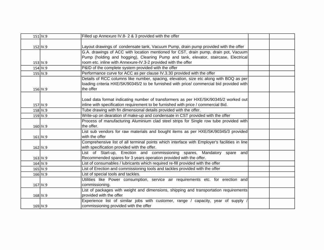
151 IV.9 Filled up Annexure IV.8- 2 & 3 provided with the offer
152 IV.9 Layout drawings of condensate tank, Vacuum Pump, drain pump provided with the offer
153 IV.9
G.A. drawings of ACC with location mentioned for CST, drain pump, drain pot, VacuumPump (holding and hogging), Cleaning Pump and tank, elevator, staircase, Electricalroom etc. inline with Annexure-IV.3-2 provided with the offer
154 IV.9 P&ID of the complete system provided with the offer155 IV.9 Performance curve for ACC as per clause IV.3.30 provided with the offer
156 IV.9
Details of RCC columns like number, spacing, elevation, size etc along with BOQ as perloading criteria HXE/SK/90345/2 to be furnished with price/ commercial bid provided withthe offer
157 IV.9
Load data format indicating number of transformers as per HXE/SK/90345/2 worked outinline with specification requirement to be furnished with price / commercial Bid.
158 IV.9 Tube drawing with fin dimensional details provided with the offer.159 IV.9 Write-up on dearation of make-up and condensate in CST provided with the offer
160 IV.9
Process of manufacturing Aluminium clad steel strips for Single row tube provided withthe offer.
161 IV.9
List sub vendors for raw materials and bought items as per HXE/SK/90345/3 providedwith the offer
162 IV.9
Comprehensive list of all terminal points which interface with Employer's facilities in linewith specification provided with the offer.
163 IV.9
List of Start-up, Erection and commissioning spares, Mandatory spare andRecommended spares for 3 years operation provided with the offer.
164 IV.9 List of consumables / lubricants which required re-fill provided with the offer165 IV.9 List of Erection and commissioning tools and tackles provided with the offer166 IV.9 List of special tools and tackles.
167 IV.9
Utilities like Power consumption, service air requirements etc. for erection andcommissioning.
168 IV.9
List of packages with weight and dimensions, shipping and transportation requirementsprovided with the offer
169 IV.9
Experience list of similar jobs with customer, range / capacity, year of supply /commissioning provided with the offer
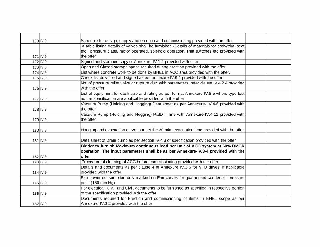
170 IV.9 Schedule for design, supply and erection and commissioning provided with the offer
171 IV.9
A table listing details of valves shall be furnished (Details of materials for body/trim, seatetc., pressure class, motor operated, solenoid operation, limit switches etc provided withthe offer
172 IV.9 Signed and stamped copy of Annexure-IV.1-1 provided with offer173 IV.9 Open and Closed storage space required during erection provided with the offer174 IV.9 List where concrete work to be done by BHEL in ACC area provided with the offer.175 IV.9 Check list duly filled and signed as per annexure IV.9-1 provided with the offer
176 IV.9
No. of pressure relief valve or rupture disc with parameters, refer clause IV.4.2.4 providedwith the offer
177 IV.9
List of equipment for each size and rating as per format Annexure-IV.8-5 where type testas per specification are applicable provided with the offer
178 IV.9
Vacuum Pump (Holding and Hogging) Data sheet as per Annexure- IV.4-6 provided withthe offer
179 IV.9
Vacuum Pump (Holding and Hogging) P&ID in line with Annexure-IV.4-11 provided withthe offer
180 IV.9 Hogging and evacuation curve to meet the 30 min. evacuation time provided with the offer
181 IV.9 Data sheet of Drain pump as per section IV.4.3 of specification provided with the offer
182 IV.9
Bidder to furnish Maximum continuous load per unit of ACC system at 60% BMCRoperation. The input parameters shall be as per Annexure-IV.3-4 provided with theoffer
183 IV.9 Procedure of cleaning of ACC before commissioning provided with the offer
184 IV.9
Details and documents as per clause 4 of Annexure IV.3-6 for VFD drives, if applicableprovided with the offer
185 IV.9
Fan power consumption duly marked on Fan curves for guaranteed condenser pressurepoint (160 mm Hg)
186 IV.9
For electrical, C & I and Civil, documents to be furnished as specified in respective portionof the specification provided with the offer
187 IV.9
Documents required for Erection and commissioning of items in BHEL scope as perAnnexure-IV.9-2 provided with the offer

188 IV.10
Documents, detail drawings as per clause IV.10 and clause XV.4 with minimum documents as per
Annexure XV‐1 shall be furnished by Bidder after award of contact.
189 Clasue VIII Terminal Points shall be as per the specication. Vendor to confirm.
190 IX Layout andd safety consideration shall be as per clause
191 X
Bidder to confirm that supervision of erection and commissioning shall be done by Bidder in
agreement with Clause X of specification.
192 X.1.5 Bidder to confirm the requirement of the clause
193 X.1.6, X.1.7 Bidder to confirm the requirement of the clause
194
X.1.8, X.1.9, X.1.10,
X.1.23 Bidder to confirm the requirement of the clause
195 XI
System cleaning and flushing shall confirm to clause XI of BHEL specification during
commissioning.
196 XII
Erection, commissioning, start‐up, trial operation, and Performance Testing shall confirm to
clause XII of BHEL specification
197
XIV.1 and Annexure‐
XIV.1‐1, X.1.4
Training as per clauses included in the offer. Details of training module as per clause XIV
furnished.
198
XIV.2 and Annexure‐
XIV.2‐1 3D modelling to be done as per clause
199 XV
Bidder to confirm the requirement specified as per clause XV of BHEL specification regarding
Project Monitoring Schedule.
200 XVI
Bidder to adhere the requirement of clause XVI (packing and transportation) as per BHEL
specification
201 Annexure‐IV.3‐5 Expected Steam/Water Quality during Normal Operation
202 Annexure‐IV.3‐2 Transformer and stringing arrangement as per Annexure. ACC shall be designed accordingly.
203 Annexure‐IV.5‐1 Painiting shall be as per Annexure.

CONTROL AND INSTRUMENTATION
Sl. No. Clause no. Check Point YES/ No Remarks
1 VI.1.1 Confirmation of Scope of Supply
2 VI.2 All System design parameters/requirements accepted?
3 VI.2.2 Acceptance of redundancy criteria including Dual and Triple Measurement scheme
4 VI.3.1 All requirements of cables accepted?
5 VI.3.2, VI.3.3 Specification of Junction box & Terminal blocks accepted?
6 VI.3.4 All requirements of conduits accepted?
7 VI.3.5 Requirement of cable trays routing acceptable?
8 VI.3.6 All requirements in specification of Instrumentation cable accepted?
9 VI.3.7
Confirmation of acceptance of instrumentation cable interconnection and
termination philosophy
10 VI.4 Confirmation to provide electronic transmitters with HART protocol
11 VI.4.1 Confirmation to provide Temperature Transmitters with all Temperature elements
12 VI.4.1
Confirmation to provide atleast one dual input transmitter for temperature
measurements used in trip/major interlock/protection.
13 VI.4.1 Confirmation to provide instruments as per the listed requirement.
14 VI.4.2 Specification for temperature measurements acceptable?
15 VI.4.3 Specification for pressure measurements acceptable?
16 VI.4.4 Specification for level measurements acceptable?
17 VI.4.6
Confirmation of acceptance of technical requirements for control valve, actuators &
accessories in Annexure VI.III
18 VI.4.6.5 Specification for Solenoid Valves acceptable?
19 VI.4.6.9
Confirmation of acceptance of technical requirements for Electric Actuators with Integral
Starters in Annexure VI.I
20 VI.4.7.1
Confirmation of acceptance of specification for Electronic Transmitters for Level
Measurement
21 VI.4.7.2 Confirmation of acceptance of specification for Guided Wave Radar type Level Transmitter
22 VI.4.7.3 confirmation of acceptance of specification of ultrasonic type level transmitter.
23 VI.4.7.4 confirmation of supply of HART hand held calibrator as per clause VI.4.7.4
24 VI.4.7.6 confirmationof acceptance of specification for process actuated switches .
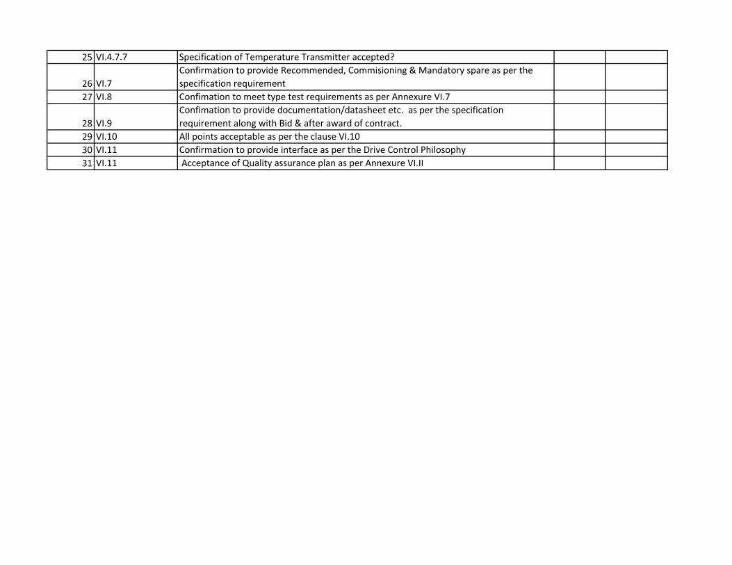
25 VI.4.7.7 Specification of Temperature Transmitter accepted?
26 VI.7
Confirmation to provide Recommended, Commisioning & Mandatory spare as per the
specification requirement
27 VI.8 Confimation to meet type test requirements as per Annexure VI.7
28 VI.9
Confimation to provide documentation/datasheet etc. as per the specification
requirement along with Bid & after award of contract.
29 VI.10 All points acceptable as per the clause VI.10
30 VI.11 Confirmation to provide interface as per the Drive Control Philosophy
31 VI.11 Acceptance of Quality assurance plan as per Annexure VI.II
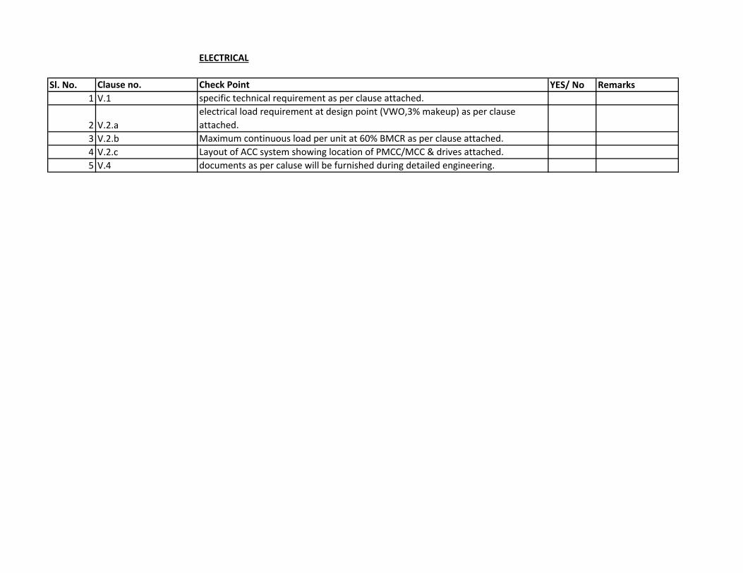
ELECTRICAL
Sl. No. Clause no. Check Point YES/ No Remarks
1 V.1 specific technical requirement as per clause attached.
2 V.2.a
electrical load requirement at design point (VWO,3% makeup) as per clause
attached.
3 V.2.b Maximum continuous load per unit at 60% BMCR as per clause attached.
4 V.2.c Layout of ACC system showing location of PMCC/MCC & drives attached.
5 V.4 documents as per caluse will be furnished during detailed engineering.

NTPC Patratu:3X800MW
Clarification No:10
BHEL Doc. Reference Description Bidder Query BHEL Reply
Annexure IV 1.1 Scope list Scope list to be updated considering all tender amendments/corrigendum issued till date.
Refer Sl. No.01 of amendment 08
Annexure IV 9.1 Check list Sr.No 1 ,Clause No.1.1
Confirmation on Scope of Proposal.
Whether the ‘Scope’ refers to Annexure IV 1.1? Please clarify.
Refer Sl. No.01 of amendment 08. Annexure IV.1‐1 is scope for major mechanical items only. refer “Note” in Annexure IV.1‐1 for better clarity.
Annexure IV 9.1 Check list Sr.No.2 Clause No.1.1
Ensured Additional requirement.
What Additional requirement? Please clarify.
Refer Cl.No I.1, Additional requirements, at page 04 of 121 of HE57070
Annexure IV 9.1 Check list Sr.No.31, Clause no.IV3.25, Annexure IV 3.6
……Any other Drives with VFD shall comply with requirements‐‐‐‐
Clarify whether motor has to be suitable for VFD drives or DOL.
Fan Motor shall be as per cl.No IV.3.25 of HE57070. However motors for other components and system may be given as per Annexure IV.3‐6.
Annexure IV 9.1 Check list Sr.No.49, Clause No. IV 4.3.6
Drain pumps 2 X 100% capacity…for each unit, including one number canister drainage pump per station shall be provided…..
Clarity required on type of Drain pump from Canister drain pump.
Refer Sl.No.11 of amendment 08
Annexure IV 9.1 Check list Sr.Nos.58, 59, 60 & 61.Clause Nos. IV 4.4.3, 4.4.4 & 4.4.6
Material of tube, manufacturing process, anti‐ corrosion treatment, etc.
Clarity required on material requirement, process of cladding and also on SRT testing.
No further clarification.
Annexure IV 9.1 Check list Sr.No.68, Clause No. IV 4.5.1.4
Fan blades shall be FRP or Glass fibre‐reinforced plastic or equivalent….
Any special coating required on Fan Blades?
No other special requirement.
Annexure IV 9.1 Check list Sr.No.80 & 84,Clause No.IV 4.5.2.2,4.5.2.15
Gearbox shall be designed as per AGMA. Gearbox shall have fan vibration switch measurement device and SPM nipple measurement for local vibration measurement.
Service Factor for gear box required. SPM is indicated then it will not be of Vibration switch. We have to provide Velometer or Vibration transducer‐‐‐Kindly confirm.
For service factor, refer cl. No IV.4.5.2.1 at page 33 of 121 of spec HE57070 Refer Sl. No.06 of amendment 08.
Quality of heat exchanger tubes.
We apply distinctive quality measures to ensure
No other special requirement.
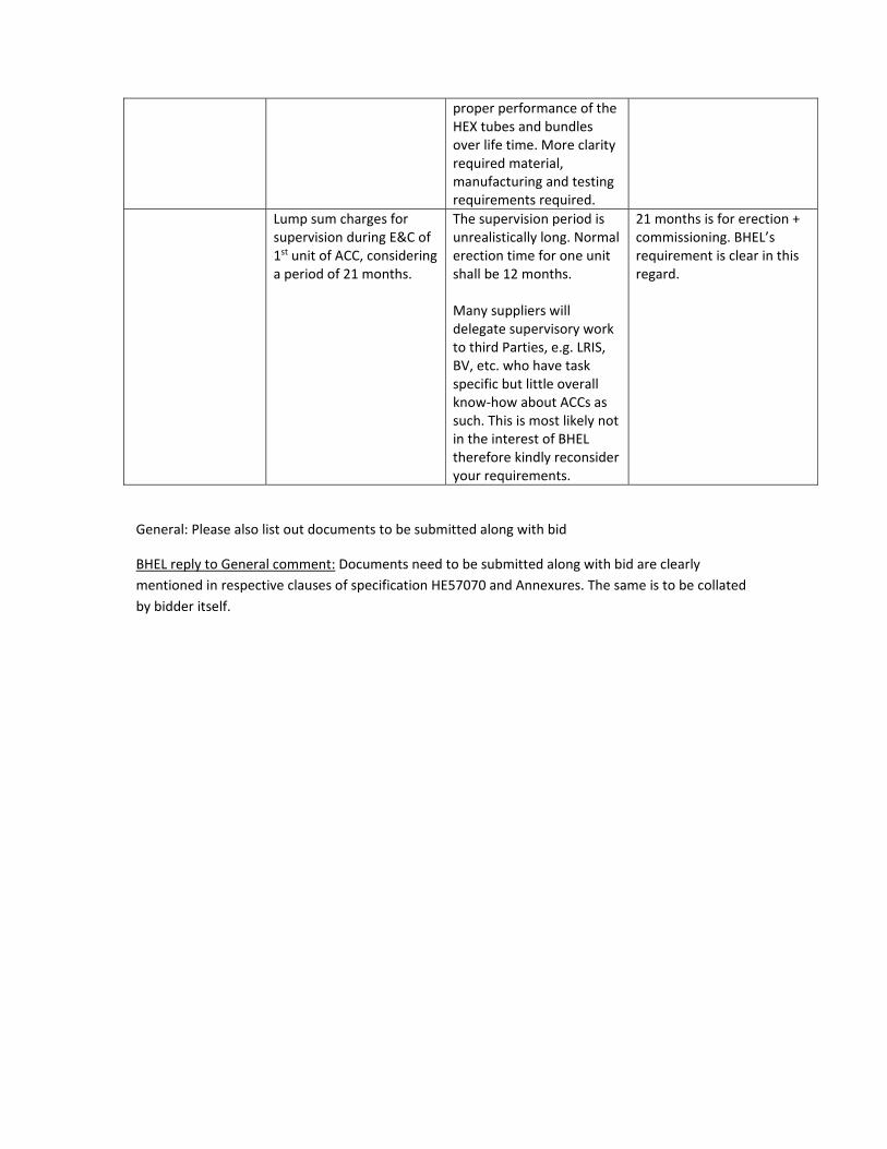
proper performance of the HEX tubes and bundles over life time. More clarity required material, manufacturing and testing requirements required.
Lump sum charges for supervision during E&C of 1st unit of ACC, considering a period of 21 months.
The supervision period is unrealistically long. Normal erection time for one unit shall be 12 months. Many suppliers will delegate supervisory work to third Parties, e.g. LRIS, BV, etc. who have task specific but little overall know‐how about ACCs as such. This is most likely not in the interest of BHEL therefore kindly reconsider your requirements.
21 months is for erection + commissioning. BHEL’s requirement is clear in this regard.
General: Please also list out documents to be submitted along with bid
BHEL reply to General comment: Documents need to be submitted along with bid are clearly
mentioned in respective clauses of specification HE57070 and Annexures. The same is to be collated
by bidder itself.