measuring solar signal in a radio telescope david christopher balding march 16, 2005 south carolina...
TRANSCRIPT

Measuring Solar SignalMeasuring Solar SignalIn A Radio TelescopeIn A Radio Telescope
David Christopher BaldingDavid Christopher BaldingMarch 16, 2005March 16, 2005
South Carolina Junior Academy of ScienceSouth Carolina Junior Academy of Science

How It All Came AboutHow It All Came About
Research project done in Research project done in Sophomore English Class Sophomore English Class on Apollo Missionson Apollo Missions
Met Dr. John Bernard who Met Dr. John Bernard who is a Radio Astronomer is a Radio Astronomer
Began interest in becoming Began interest in becoming a future astronaut a future astronaut
The Main PurposeThe Main Purpose
The purpose of this project were these The purpose of this project were these reasons:reasons:
To further my knowledge in Radio AstronomyTo further my knowledge in Radio Astronomy
To further my interest in spaceTo further my interest in space
To work toward becoming an astronaut To work toward becoming an astronaut
In the beginning…In the beginning…
First step was to put together a radio First step was to put together a radio astronomy station that could be used near astronomy station that could be used near my home in rural Pickens County, SCmy home in rural Pickens County, SC
The next step was to get inexpensive The next step was to get inexpensive receiving equipment to usereceiving equipment to use
Final step was to align the radio telescopeFinal step was to align the radio telescope
The ProcessThe Process
The following process was used in getting The following process was used in getting the radio telescope set up accurately:the radio telescope set up accurately:
Use a C-band setup and move the dish the Use a C-band setup and move the dish the latitude of the sun’s position, due Southlatitude of the sun’s position, due South
Run audio analysis software on a Run audio analysis software on a computer connected to the audio output of computer connected to the audio output of the receiverthe receiver
Main Application ProblemsMain Application Problems
With all the hardware and software running, this With all the hardware and software running, this was the received spectral data:was the received spectral data:
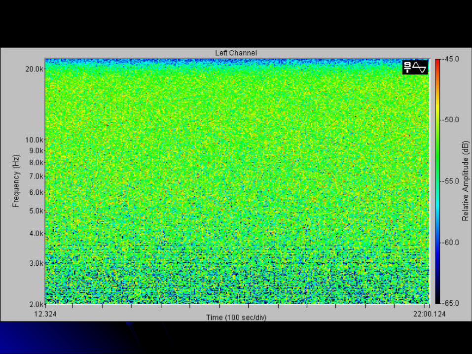

Application ProblemsApplication Problems
As one can see the relative amplitude of As one can see the relative amplitude of the solar signal did not increase or the solar signal did not increase or decrease as expecteddecrease as expected
The db level stayed constant around -52 The db level stayed constant around -52
These results presented problems with the These results presented problems with the experimentexperiment

SolutionSolutionAfter several reattempts and suggestions After several reattempts and suggestions
from my mentors it seemed that the AGC from my mentors it seemed that the AGC or auto gain control built into the receiver or auto gain control built into the receiver was causing the audio level to remain was causing the audio level to remain constantconstant
A custom built receiver with AGC circuit A custom built receiver with AGC circuit removed was triedremoved was tried

ResultsResults I received the same picture of data after reattempts.I received the same picture of data after reattempts.

Temporary SolutionTemporary Solution
Still had problems… The conclusion after Still had problems… The conclusion after several reattempts with the new receiver in several reattempts with the new receiver in line, was that the receiver was being line, was that the receiver was being overloaded with too much signaloverloaded with too much signal
As a temporary solution, two copper As a temporary solution, two copper probes were put inline between the probes were put inline between the receiver and the radio telescope receiver and the radio telescope connectors… letting the signal radiate…connectors… letting the signal radiate…

Success!!Success!!After the probes were put inline the below After the probes were put inline the below
signal/data was received:signal/data was received:


Fixed SolutionFixed Solution
As you can see the data shows an As you can see the data shows an increase in relative amplitude then a short increase in relative amplitude then a short peak, then finally a decrease.peak, then finally a decrease.
So to have a controlled variable, a project So to have a controlled variable, a project built variable attenuator was inserted.built variable attenuator was inserted.
This put attenuation inline just like the This put attenuation inline just like the probes did earlier.probes did earlier.
The following picture of data was received. The following picture of data was received.

Future WorkFuture WorkAfter the success of building, aligning, and After the success of building, aligning, and
testing a radio telescope, my plans are to do testing a radio telescope, my plans are to do the following:the following:Explore outer space using the radio Explore outer space using the radio
telescope to find other radio sourcestelescope to find other radio sources
To do a transit on Sagittarius A and compare To do a transit on Sagittarius A and compare and contrast data from it to the sunand contrast data from it to the sun
To promote interest in space to younger To promote interest in space to younger students in schoolstudents in school
Special ThanksSpecial Thanks
Special Thanks goes to:Special Thanks goes to:Doug FaganDoug FaganDr. John D BernardDr. John D BernardCrenshaw Satellite Television Crenshaw Satellite Television Carl LysterCarl LysterMrs. WatsonMrs. Watson