measurement of soil water content during three-dimensional axial-symmetric water flow
TRANSCRIPT

Measurement of Soil Water Content during Three-Dimensional Axial-SymmetricWater Flow
R. G. Kachanoski,* I. J. Van Wesenbeeck, P. Von Bertoldi, A. Ward, and C. Hamlen
ABSTRACTThe objective of this work was to develop a method of measuring
soil water content during three-dimensional axial-symmetric waterflow in a laboratory column. A small plexiglass box with a pair ofstraight and a pair of curved, parallel transmission lines was con-structed, packed with soil, saturated with water, and then left to dryout. Soil water content measurements using the time-domain reflec-tometry (TDK) method were made using both curved and straighttransmission lines. A large laboratory flow box was also constructedwith numerous curved TDR probes at different radial distances fromone vertical edge of the box. The box was packed with soil and thenwater was applied from a small surface disc source, (radius = 15mm) at the corner of the box. Soil water content was measuredduring the three-dimensional infiltration experiment. Measured soilwater contents were essentially identical (r2 = 0.98) for both thestraight and curved lines. The method gave soil water content as afunction of time for different radial distances from the point source,or the spatial distribution at different time intervals. The estimatedamounts of infiltrated water obtained by numerical integration ofsoil water content vs. radial distance at 1 and 1 h were within 3%of the measured infiltration amount. The method can be used to testand study the theory of three-dimensional axial-symmetric flow ofwater into soil.
ANUMBER OF STUDIES have examined three-dimen-sional infiltration because of its relevance to
many field situations such as trickle irrigation (Philip,1966; Philip, 1971; Raats, 1971; Brandt et al., 1971;Parlange, 1972). The mathematical expressions de-rived for axial-symmetric flow of water in soil havenot been thoroughly tested because of the difficulty inobtaining measurements of anything other than thelocation of the wetting front and the rate of infiltra-tion. The need for supplementing wetting-front ob-servations during axial-symmetric flow with measure-Dep. of Land Resource Science, University of Guelph, Guelph, On-tario, Canada NIG 2W1. Received 26 May 1989. Correspondingauthor.
Published in Soil Sci. Soc. Am. J. 54:645-649 (1990).
ments of either soil water content or matric potentialhas been expressed by Philip (1969). He indicated thatapproximate radial symmetry in the observed wettingfront does not necessarily imply the nonemergence ofasymmetries in flow (and thus water content) behindthe wetting front, due to gravity effects.
Bresler et al. (1971) measured soil-water-contentdistributions during infiltration from a point sourceinto a thin (40-mm) rectangular column of soil usingthe gamma attenuation method. However, flow wastwo dimensional (planar) not three dimensional.Clothier and Scotter (1982) and Clothier and Elrick(1985) measured soil-water-content distributionsalong the horizontal, diagonal, and vertical axes dur-ing constant-flux infiltration from a point source.They destructively sampled their flow columns anddetermined water content gravimetrically. Theirmethod gave good results but required a differenthand-packed column for each replication and time-step of interest and might be impractical for experi-ments with transient boundary conditions or where alarge number of time-steps are of interest. A methodof rapidly and nondestructively measuring soil-water-content distribution during three-dimensional axial-symmetric water flow is needed. Recently, Stephensand Heermann (1988) examined streamlines andequipotential lines during flow from a point source,using dyes and tensiometers installed in a laboratoryflow box similar to Clothier and Scotter (1982).
This paper presents a method for measuring soilwater content along a curved line of interest using amodification of the TDR method (Topp et al., 1980).
The TDR method of measuring volumetric soilwater content has been thoroughly discussed and ex-amined in the soil science and earth science literature(Topp et al., 1980, 1982; Dasberg and Dalton, 1985).The TDR technique provides a low-cost, accurate,rapid, and nondestructive method of measuring vol-umetric soil water content. The TDR water measure-ments are relatively unaffected by soil texture, density,
646 SOIL SCI. SOC. AM. J., VOL. 54, MAY-JUNE, 1990
temperature, or salt content. We used the TDRmethod to measure soil water content along a curvedline of interest. The method was used to measure soilwater content along different radial lines from the axisof flow symmetry (vertical) during three-dimensionalinfiltration of water from a surface source.
MATERIALS AND METHODSThe TDR determination of soil water content involves
measurement of the propagation of an electromagnetic wavein soil. A step voltage pulse is usually propagated along apair of straight parallel transmission rods or wires insertedinto the soil, which acts as a transmission line. The straightparallel rods or wires serve as conductors, and the soil be-tween the conductors is the dielectric medium. The rods orwires act as a wave guide and the signal propogates as aplane wave (Topp and Davis, 1985).
When tfee plane wave reaches the end of the transmissionlines, it is reflected back. The time interval between whenthe waver enters the soil and when it is reflected back canbe measured with an instrument such as a portable cabletester. Since the length of the straight parallel lines is known,the propagation velocity of the plane wave can then be cal-culated. The dielectric constant of the soil, which is pri-marily a function of soil water content (Topp et al., 1980),can be calculated from the propagation velocity. Thus, thesoil water content can be obtained from knowledge of thelength of the transmission line and a measurement of theplane-wave travel time.
To date, all published applications of the TDR methodhave used straight parallel transmission lines inserted intothe soil. However, the two parallel rods act as a wave guideand there is no theoretical requirement that they be straight.It has just been convenient to push two straight parallel rodsinto the soil. If the parallel line is curved, the plane waveshould still, theoretically, follow between the rods or wires,but the travel length would now be the arc length ratherthan the straight length between the beginning and end ofthe transmission lines. Thus, the average soil water contentalong the curved plane between the curved transmissionlines could be obtained by measuring the plane-wave traveltime and knowing the curved probe length.
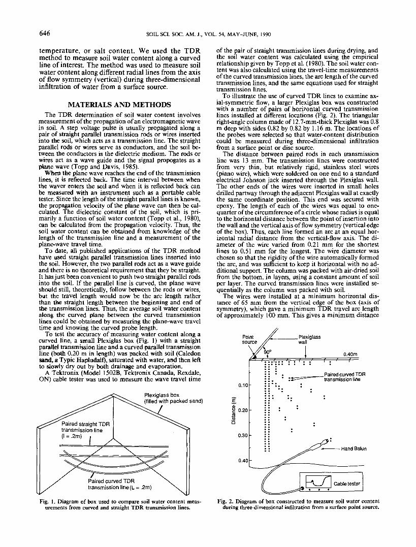
To test the accuracy of measuring water content along acurved line, a small Plexiglas box (Fig. 1) with a straightparallel transmission line and a curved parallel transmissionline (both 0.20 m in length) was packed with soil (Caledonsa»d, a Typic Hapludalf), saturated with water, and then leftto slowly dry out by both drainage and evaporation.
A Tektronix (Model 1502B, Tektronix Canada, Rexdale,ON) cable tester was used to measure the wave travel time
Plexiglass box(filled with packed sand)
Paired straight TDRtransmission line(I = .2m) .
Paired curved TDRtransmission line(L = .2m)
of the pair of straight transmission lines during drying, andthe soil water content was calculated using the empiricalrelationship given by Topp et al. (1980). The soil water con-tent was also calculated using the travel-time measurementsof the curved transmission lines, the arc length of the curvedtransmission lines, and the same equations used for straighttransmission lines.
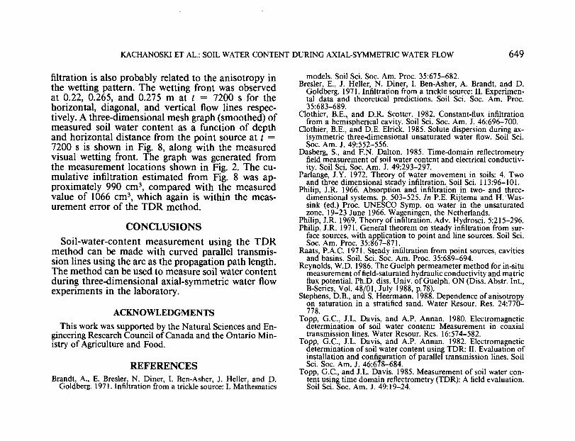
To illustrate the use of curved TDR lines to examine ax-ial-symmetric flow, a larger Plexiglas box was constructedwith a number of pairs of horizontal curved transmissionlines installed at different locations (Fig. 2). The triangularright-angle column made of 12.7-mm-thick Plexiglas was 0.8m deep with sides 0.82 by 0.82 by 1.16 m. The locations ofthe probes were selected so that water-content distributioncould be measured during three-dimensional infiltrationfrom a surface point or disc source.
The distance between paired rods in each transmissionline was 13 mm. The transmission lines were constructedfrom very thin, but relatively rigid, stainless steel wires(piano wire), which were soldered on one end to a standardelectrical Johnson jack inserted through the Plexiglas wall.The other ends of the wires were inserted in small holesdrilled partway through the adjacent Plexiglas wall at exactlythe same coordinate position. This end was secured withepoxy. The length of each of the wires was equal to one-quarter of the circumference of a circle whose radius is equalto the horizontal distance between the point of insertion intothe wall and the vertical axis of flow symmetry (vertical edgeof the box). Thus, each line formed an arc at an equal hor-izontal radial distance from the vertical-flow axis. The di-ameter of the wire varied from 0.21 mm for the shortestlines to 0.51 mm for the longest. The wire diameter waschosen so that the rigidity of the wire automatically formedthe arc, and was sufficient to keep it horizontal with no ad-ditional support. The column was packed with air-dried soilfrom the bottom, in layers, using a constant amount of soilper layer. The curved transmission lines were installed se-quentially as the column was packed with soil.
The wires were installed at a minimum horizontal dis-tance of 65 mm from the vertical edge of the box (axis ofsymmetry), which gave a minimum TDR travel arc lengthof approximately 100 mm. This gives a minimum distance
Plexiglasswall
0.40m
0.10
0.20
0.30
0.40
. Paired curved TDRtransmission line
Hand Balun
Fig. 1. Diagram of box used to compare soil water content meas-urements from curved and straight TDR transmission lines.
Fig. 2. Diagram of box constructed to measure soil water contentduring three-dimensional infiltration from a surface point source.

KACHANOSKI ET AL.: SOIL WATER CONTENT DURING AXIAL-SYMMETRIC WATER FLOW 647
along the diagonal, from a point source in the corner of thebox, of 92 mm.
The soil used was the C horizon of Caledon sand, whichhad been air dried, sieved through a 1-mm round-hole sieve,and mechanically mixed to maximize homogeneity. Theparticle-size distribution (Reynolds, 1986) is 1.0% clay, 6.7%silt, and 92.3% sand. The saturated hydraulic conductivityis approximately 8.8 X 1Q-6 m s'1 (Reynolds, 1986).
Water was supplied to the corner of the box from a smallquarter-circle source (r0 = 15 mm) maintained at a constantnegative pressure head \f/0 — — 0.10 m. The point source wasconstructed by stretching a fine nylon mesh over the end ofa cylinder with a quarter-circle cross-sectional shape. Thesource was maintained at a constant negative pressure headby attaching the cylinder to a Mariotte bottle, which wasalso used to determine the infiltration rate by monitoringthe change in weight of the bottle with time using an elec-tronic balance. The initial soil water content for the flowexperiment was 0, = 0.01 m3 m-3.
RESULTS AND DISCUSSIONThe calculated soil water contents using straight and
curved transmission lines are essentially identical (r2
= 0.98), indicating the TDK method can be used tomeasure soil water content along a curved line of in-terest with the same accuracy as along straight trans-mission lines (Fig. 3).
c £• .20
'S
.10
r2 = 0.98Slope = 0.98
.10 .20 .30
Water content (m3 m"3)curved probe
Fig. 3. Comparison of soil water content measurements from curvedand straight TDK transmission lines.
Vertical flow axis
Fig. 4. Application of curved time-domain reflectometry transmis-sion lines to measure water content during axial-symmetric flowin laboratory columns.
During axial-symmetric flow, hydraulic variablesincluding soil water content are symmetric along anyhori/ontal radial distance from the vertical flow axis.For a point source of water, this also implies a de-pendence of soil water content on the radial distanceto the point source. Thus, curved parallel transmis-sion lines set at an equal horizontal radial distancefrom a vertical flow axis can measure soil water con-tent in the correct geometry for axial-symmetric flowexperiments (Fig. 4). In addition, since flow is axial-symmetric, it is possible to work with one-quarter ofthe flow geometry and use water sources at the cornerof a box, in a manner similar to Clothier and Scotter(1982). The flow experiment was used to demonstratethe application of using curved TDK probes for meas-uring the spatial and temporal distributions of soilwater content during axial-symmetric water flow.
The infiltration rate was essentially constant at 1.42X 10⁻⁵ m3 s-1 (8.0 X 10⁻⁶ m $-') after approximately50 min (Fig. 5). Cumulative infiltration after 1 and 2h was 555 cm3 and 1066 cm3, respectively.
Measured soil water contents as a function of time,for three radial distances from the point source (cornerof the box) along the diagonal of the flow box, areshown in Fig. 6. The time that the visual wetting frontreached each of the measurement locations is also
2000 4000 6000Time (s)
Fig. 5. Measured cumulative infiltration using curved time-domainreflectometry transmission lines.
0.25 r
£~ 0.15c0)cooJj 0.10co
0.05
r = 0.092 Mr = 0.147M
0.184Minitial 6
Visual wetting frontI , , I
3000 6000
Time (s)9000 12000
Fig. 6. Measured soil water content as a function of time at differentradial distances along the diagonal, using curved time-domain re-flectometry transmission lines.

648 SOIL SCI. SOC. AM. J., VOL. 54, MAY-JUNE, 1990
shown in Fig. 6 and indicates good agreement withthe measured soil water contents using the curvedtransmission lines. The scatter in the measured soilwater contents around the hand-fitted line is attrib-uted to small errors in estimating wave travel timedirectly from the screen trace of the cable tester. Meas-urements were taken quickly in order to scan as manylocations as possible. The scatter in the measurementsis greater at smaller radial distances because the traveltime of the wave is shorter and any error in estimatedtravel time has a much greater effect in calculated soilwater contents. The measured changes in soil watercontents at a given location are generally smooth, in-dicating a rapid increase immediately after the arrivalof the wetting front (Fig. 6).
A problem was encountered with an overestimationof soil water contents at values less than about 0.06m3 nr3, and only measurements greater than this wereused in the analysis. The problem is not related to theuse of curved TDR lines, but appears to be a problemwith the TDR method in general at very low soil water
0.30 -
— 0.20
8oo5 0.10 -
oto
Visualwetting front
— t = 3600st = 7200s —*J
• gravimetric (final)o—o TDR, t = 3600sa—a TDR, t = 7200s
0.05 0.10 0.15 0.20 0.25 0.30
Radial distance (m)Fig. 7. Measured soil water content as a function of radial distance
along the diagonal at two times, using curved time-domain re-flectometry transmission lines.
Point source
contents. Close examination of the calibration curvebetween predicted (TDR) and actual soil water con-tents from Topp et al. (1982) indicates that the TDRmethod overestimates soil water contents for valuesless than about 0.06 m3 m-3. Topp et al. (1983) statethat the calibration curve has not been thoroughlytested at very low or high soil water contents. In gen-eral, the lack of usable measurements at very low soilwater contents is not a serious limitation. The soilwater content quickly rises above 0.06 m3 mr3 and, byusing the measurements of the wetting-front locationthe low soil-water-content values can be estimated asin Fig. 6.
Soil-water-content distributions as a function of ra-dial distance along the diagonal for time t = 3600 and7200 s are shown in Fig. 7. The visually measuredlocation of the wetting front was again used to ex-trapolate the soil-water-content estimates in the lowrange. The hand-fitted curves in Fig. 7 were extrapo-lated back to 0.32 m3 m-3 for r — 5 mm, which wasmeasured gravimetrically at the end of the experi-ment. The values of soil water content for small radialdistances changed very little at longer time intervals.
Cumulative infiltration was estimated numerically(Fig. 7) by assuming the soil-water-content distribu-tion along the diagonal (Fig. 7) was representative ofthe entire wetted region. The estimated cumulativeinfiltration was 540 cm3 and 1170 cm3, compared withthe measured values of 555 cm3 and 1066 cm3, for t= 3600 and 7200 s, respectively. The visual wettingfront indicated the total wetted volume of soil wasapproximately 3480 cm3 and 9740 cm3 for t = 3600and 7200 s, respectively. Thus, the difference betweenestimated and measured cumulative infiltration rep-resents an average error in measured soil water con-tent of approximately 0.005 to 0.01 m3 m^3, which isthe approximate resolution of the TDR method (Toppet al., 1982).
The overestimation of the calculated cumulative in-
0.20 cf^/
0.300.30
Fig. 8. Mesh diagram of measured soil water contents of the wetted region after 2 h of infiltration in the large-box experiment.
KACHANOSKI ET AL: SOIL WATER CONTENT DURING AXIAL-SYMMETRIC WATER FLOW 649
filtration is also probably related to the anisotropy inthe wetting pattern. The wetting front was observedat 0.22, 0.265, and 0.275 m at t = 7200 s for thehorizontal, diagonal, and vertical flow lines respec-tively. A three-dimensional mesh graph (smoothed) ofmeasured soil water content as a function of depthand horizontal distance from the point source at t =7200 s is shown in Fig. 8, along with the measuredvisual wetting front. The graph was generated fromthe measurement locations shown in Fig. 2. The cu-mulative infiltration estimated from Fig. 8 was ap-proximately 990 cm3, compared with the measuredvalue of 1066 cm3, which again is within the meas-urement error of the TDR method.
CONCLUSIONSSoil-water-content measurement using the TDR
method can be made with curved parallel transmis-sion lines using the arc as the propagation path length.The method can be used to measure soil water contentduring three-dimensional axial-symmetric water flowexperiments in the laboratory.
ACKNOWLEDGMENTSThis work was supported by the Natural Sciences and En-
gineering Research Council of Canada and the Ontario Min-istry of Agriculture and Food.