mdt2 - scotsman ice manuals...electrical voltage variations from voltage rating specified on...
TRANSCRIPT
INTRODUCTION
This manual provides the specifications and thestep-by-step procedures for the installation,start-up, operation, maintenance and cleaning for
the SCOTSMAN MDT2 counter top cubelet icedispenser.
NOTE: To retain the safety and performance builtinto this ice machine, it is important that installationand maintenance be conducted in the manneroutlined in this manual.
MDT2
May 2003Page 1
Table of Contents
SPECIFICATIONS · · · · · · · · · · · · · · · · · · · · · · · · · · · · · · · · · · · · · · · · · · · · · Page 2
CABINET DIAGRAMS · · · · · · · · · · · · · · · · · · · · · · · · · · · · · · · · · · · · · · · · · · · Page 3
GENERAL INFORMATION AND INSTALLATION · · · · · · · · · · · · · · · · · · · · · · · · · · · · · Page 4
ELECTRICAL CONNECTIONS · · · · · · · · · · · · · · · · · · · · · · · · · · · · · · · · · · · · · · Page 5
WATER SUPPLY AND DRAIN CONNECTIONS · · · · · · · · · · · · · · · · · · · · · · · · · · · · · Page 6
FINAL CHECK LIST · · · · · · · · · · · · · · · · · · · · · · · · · · · · · · · · · · · · · · · · · · · · Page 7
OPERATING INSTRUCTIONS · · · · · · · · · · · · · · · · · · · · · · · · · · · · · · · · · · · · · · Page 8
INITIAL START UP CONTINUED · · · · · · · · · · · · · · · · · · · · · · · · · · · · · · · · · · · · · Page 9
B Series · · · · · · · · · · · · · · · · · · · · · · · · · · · · · · · · · · · · · · · · · · · · · · · · · · Page 11
SETTING THE DISPENSING SELECTOR · · · · · · · · · · · · · · · · · · · · · · · · · · · · · · · · Page 12
PRINCIPLE OF OPERATION · · · · · · · · · · · · · · · · · · · · · · · · · · · · · · · · · · · · · · · Page 13
REFRIGERANT CIRCUIT · · · · · · · · · · · · · · · · · · · · · · · · · · · · · · · · · · · · · · · · · Page 14
MECHANICAL SYSTEM · · · · · · · · · · · · · · · · · · · · · · · · · · · · · · · · · · · · · · · · · · Page 15
COMPONENT DESCRIPTION · · · · · · · · · · · · · · · · · · · · · · · · · · · · · · · · · · · · · · Page 16
COMPONENT DESCRIPTION · · · · · · · · · · · · · · · · · · · · · · · · · · · · · · · · · · · · · · Page 17
COMPONENT DESCRIPTION · · · · · · · · · · · · · · · · · · · · · · · · · · · · · · · · · · · · · · Page 18
COMPONENT DESCRIPTION · · · · · · · · · · · · · · · · · · · · · · · · · · · · · · · · · · · · · · Page 19
SERVICE DIAGNOSIS · · · · · · · · · · · · · · · · · · · · · · · · · · · · · · · · · · · · · · · · · · · Page 20
SERVICE DIAGNOSIS · · · · · · · · · · · · · · · · · · · · · · · · · · · · · · · · · · · · · · · · · · · Page 21
MAINTENANCE AND CLEANING INSTRUCTION · · · · · · · · · · · · · · · · · · · · · · · · · · · · Page 22
CLEANING INSTRUCTIONS OF WATER SYSTEM · · · · · · · · · · · · · · · · · · · · · · · · · · · Page 23
REMOVAL AND REPLACEMENT · · · · · · · · · · · · · · · · · · · · · · · · · · · · · · · · · · · · · Page 24
TOP BEARING REPLACEMENT · · · · · · · · · · · · · · · · · · · · · · · · · · · · · · · · · · · · · Page 25
BEARING REPLACEMENT - CONTINUED · · · · · · · · · · · · · · · · · · · · · · · · · · · · · · · · Page 26
WATER SEAL · · · · · · · · · · · · · · · · · · · · · · · · · · · · · · · · · · · · · · · · · · · · · · · Page 27
SPECIFICATIONSMDT2C12:
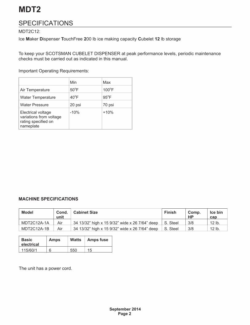
Ice Maker Dispenser TouchFree 200 lb ice making capacity Cubelet 12 lb storage
To keep your SCOTSMAN CUBELET DISPENSER at peak performance levels, periodic maintenancechecks must be carried out as indicated in this manual.
MACHINE SPECIFICATIONS
MDT2
September 2014Page 2
Model Cond.unit
Cabinet Size Finish Comp.HP
Ice bincap
MDT2C12A-1A Air 34 13/32” high x 15 9/32” wide x 26 7/64” deep S. Steel 3/8 12 lb.
MDT2C12A-1B Air 34 13/32” high x 15 9/32” wide x 26 7/64” deep S. Steel 3/8 12 lb.
Basicelectrical
Amps Watts Amps fuse
115/60/1 6 550 15
The unit has a power cord.
Important Operating Requirements:
Min Max
Air Temperature 50oF 100
oF
Water Temperature 40oF 95
oF
Water Pressure 20 psi 70 psi
Electrical voltagevariations from voltagerating specified onnameplate
-10% +10%

CABINET DIAGRAMS
MDT2
May 2002Page 3
GENERAL INFORMATION AND INSTALLATION
UNPACKING AND INSPECTION
1. Call your authorized SCOTSMAN Distributor orDealer for proper installation.
2. Visually inspect the exterior of the packing andskid. Any severe damage noted should be reportedto the delivering carrier and a concealed damageclaim form filled in subject to inspection of thecontents with the carrier’s representative present.
3. a) Cut and remove the plastic strip securing thecarton box to the skid.
b) Cut open the top of the carton and remove thepolystyrene protection sheet.
c) Pull out the polystyrene posts from the cornersand then remove the carton.
4. Retain foam pad for later use.
5. Remove the top and sides panels of the unit andinspect for any concealed damage. Notify carrier ofyour claim for the concealed damage as stated instep 2 above.
6. Remove all internal support packing andmasking tape.
7. Check that refrigerant lines do not rub against ortouch other lines or surfaces, and that the fanblades move freely.
8. Check that the compressor fits snugly onto all itsmounting pads.
9. Use clean damp cloth to wipe the surfacesoutside of the cabinet.
10. See data plate on the rear side of the unit andcheck that local main voltage corresponds with thevoltage specified on it.
CAUTION: Incorrect voltage supplied to the icemachine will void your parts replacement program.
11. Remove the manufacturer’s registration cardfrom the inside of the Users Manual and fill-in allparts including Model and Serial Number takenfrom the data plate. Forward the completedself-addressed registration card to SCOTSMANfactory.
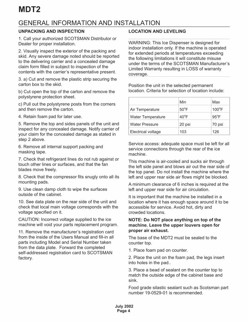
LOCATION AND LEVELING
WARNING: This Ice Dispenser is designed forindoor installation only. If the machine is operatedfor extended periods at temperatures exceedingthe following limitations it will constitute misuseunder the terms of the SCOTSMAN Manufacturer’sLimited Warranty resulting in LOSS of warrantycoverage.
Position the unit in the selected permanentlocation. Criteria for selection of location include:
Min Max
Air Temperature 50oF 100
oF
Water Temperature 40oF 95
oF
Water Pressure 20 psi 70 psi
Electrical voltage 103 126
Service access: adequate space must be left for allservice connections through the rear of the icemachine.
This machine is air-cooled and sucks air throughthe left side panel and blows air out the rear side ofthe top panel. Do not install the machine where theleft and upper rear side air flows might be blocked.
A minimum clearance of 6 inches is required at theleft and upper rear side for air circulation.
It is important that the machine be installed in alocation where it has enough space around it to beaccessible for service. Avoid hot, dirty andcrowded locations.
NOTE: Do NOT place anything on top of the
machine. Leave the upper louvers open for
proper air exhaust.
The base of the MDT2 must be sealed to thecounter top.
1. Place foam pad on counter.
2. Place the unit on the foam pad, the legs insertinto holes in the pad..
3. Place a bead of sealant on the counter top tomatch the outside edge of the cabinet base andsink.
Food grade silastic sealant such as Scotsman partnumber 19-0529-01 is recommended.
MDT2
July 2002Page 4
ELECTRICAL CONNECTIONSSee data plate for current requirements todetermine wire size to be used for electricalconnections. All SCOTSMAN ice machines requirea solid earth wire. This SCOTSMAN ice machine issupplied from the factory completely pre-wired andonly needs to be plugged into a nearby 115 voltoutlet.
Make sure that the ice machine is connected to itsown circuit and individually fused (see data platefor fuse size).
The maximum allowable voltage variation shouldnot exceed -10% and +10% of the data platerating. Low voltage can cause faulty functioningand may be responsible for serious damage to theoverload switch and motor windings.
NOTE: All external wiring should conform tonational, state and local standards and regulations.
Check voltage on the line and the ice machine’sdata plate before connecting the unit.
MDT2
May 2002Page 5
WATER SUPPLY AND DRAIN CONNECTIONS
GENERAL
When choosing the water supply for the ice flaker,consideration should be given to:
a) Length of run
b) Water clarity and purity
c) Adequate water supply pressure
Water is the most important single ingredient inproducing ice - these three items are veryimportant.
Low water pressure, below 20 psi may causemalfunction of the ice machine unit.
Water containing excessive minerals will tend toproduce scale build-up on the interior parts of thewater system while water that’s too soft (watercontains too few mineral salts), will produce a veryhard flaked ice.
PLUMBING CONNECTIONS MUST CONFORM
TO ALL APPLICABLE CODES
CONNECT TO POTABLE WATER ONLY
The model MDT2 is capable of having waterconnections through the bottom base or throughthe rear bottom side of the machine. In this secondcase it is necessary to remove the small panel atthe bottom rear.
WATER SUPPLY
Connect to the 3/4" male water inlet fitting, usingthe supplied fitting, to the cold water supply line. Ashut-off valve should be installed in an accessibleposition between the water supply line and theunit.
If the water contains a high level of impurities,consider installing a water filter or conditioner.
WATER DRAIN
The recommended drain tube is a copper, rigidplastic or reinforced flexible tubing (supplied) with.75" (19mm) I.D. which runs to an open trappedand vented drain. When the drain is a long run,allow1/4" drop per foot.
Note: Although soft, easily kinked vinyl tubing isnot recommended for a drain, a short length of ¾”ID vinyl tubing is required to connect a rigid draintube to the 20 mm (25/32”) fitting on the back ofthe MDT2.
Install a vertical open vent on the drain line highpoint at the drain connection to ensure gooddraining.
The ideal drain receptacle is a trapped and ventedfloor drain.
NOTE: The water supply and the water drain
must be installed to conform with the local
code. In some case a licensed plumber and/or
a plumbing permit is required.
MDT2
May 2002Page 6
FINAL CHECK LIST1. Is the unit in a room where the ambienttemperatures are within a minimum of 50°F even inwinter months?
2. Is there at least a 6" clearance around the unitfor proper air circulation?
3. Is the unit level?
4. Have all the electrical and plumbing connectionsbeen made, and is the water supply shut-off valveopen?
5. Has the voltage been tested and checkedagainst the data plate rating?
6. Has the water supply pressure been checked toensure a flowing water pressure of at least 20 psi.
7. Check all refrigerant lines and conduit lines toguard against vibrations and possible failure.
8. Has the unit been sealed to the counter top?
9. Has the owner/user been given the UsersManual and been instructed on the importance ofperiodic maintenance checks?
10. Has the Manufacturer’s registration card beenfilled in properly? Check the model and serialnumber against the serial plate and mail theregistration card to Scotsman.
11. Has the owner been given the name and thephone number of the authorized SCOTSMANService Agency serving them?
MDT2
May 2002Page 7

OPERATING INSTRUCTIONSINITIAL START UP
After having correctly installed the ice machine andcompleted the plumbing and electricalconnections, perform the following “Start-up”procedure.
Remove the control board inspection panel andcover to view the lights on the control board.
A. Open the water supply line shutoff valve andturn the main switch on the power supply line tothe ON position.
The GREEN LED will glow to signal that unit isunder power.
NOTE: Every time the unit is turned on after beingshut off for a period of time (electricallydisconnected) the 2
nd RED LED will blink for 3 minutes (Fig.1).
B. After 3 minutes have elapsed – the stand byperiod – the unit starts operating by activatingsystems in following sequence:
1. GEAR MOTOR
2. COMPRESSOR
3. FAN MOTOR – which is controlled by thecondenser temperature sensor. The probe iswithin the condenser fins.
4. 2nd
RED LED switches off (Fig. 2).
C. Two or three minutes after compressor start up;cubelet ice should begin dropping off the ice spoutinto the storage bin.
MDT2
May 2003Page 8
Fig 1
Bin fullBin empty
Reset button
Hi cond temp when Steady3 minute wait when Blinking No water
PowerAuger Motor when SteadyHi evap temp when Blinking
Fig 2
Bin fullBin empty
Reset button
No water
Power
Hi cond temp when Steady3 minute wait when Blinking
Auger Motor when SteadyHi evap temp when Blinking
Normally Off
BLINKING – 3 MIN.STAND-BY PERIOD
INITIAL START UP CONTINUED
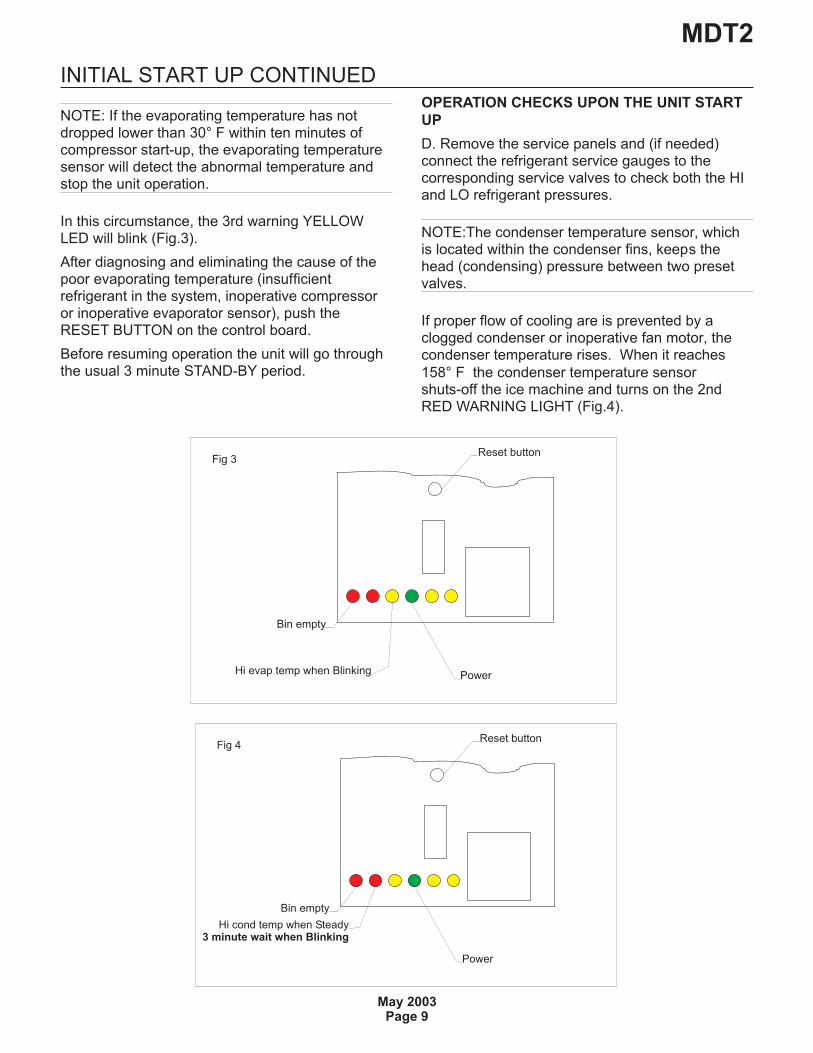
NOTE: If the evaporating temperature has notdropped lower than 30° F within ten minutes ofcompressor start-up, the evaporating temperaturesensor will detect the abnormal temperature andstop the unit operation.
In this circumstance, the 3rd warning YELLOWLED will blink (Fig.3).
After diagnosing and eliminating the cause of thepoor evaporating temperature (insufficientrefrigerant in the system, inoperative compressoror inoperative evaporator sensor), push theRESET BUTTON on the control board.
Before resuming operation the unit will go throughthe usual 3 minute STAND-BY period.
OPERATION CHECKS UPON THE UNIT START
UP
D. Remove the service panels and (if needed)connect the refrigerant service gauges to thecorresponding service valves to check both the HIand LO refrigerant pressures.
NOTE:The condenser temperature sensor, whichis located within the condenser fins, keeps thehead (condensing) pressure between two presetvalves.
If proper flow of cooling are is prevented by aclogged condenser or inoperative fan motor, thecondenser temperature rises. When it reaches
158° F the condenser temperature sensorshuts-off the ice machine and turns on the 2ndRED WARNING LIGHT (Fig.4).
MDT2
May 2003Page 9
Fig 3
Bin empty
Reset button
PowerHi evap temp when Blinking
Fig 4
Bin empty
Reset button
Power
Hi cond temp when Steady3 minute wait when Blinking
After diagnosing and fixing the cause of thetemperature rise, push the RESET BUTTON onthe control board.
Before resuming operation the unit will go throughthe usual 3 minute STAND-BY period.
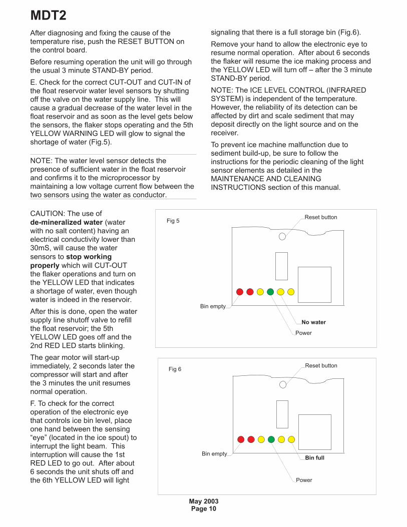
E. Check for the correct CUT-OUT and CUT-IN ofthe float reservoir water level sensors by shuttingoff the valve on the water supply line. This willcause a gradual decrease of the water level in thefloat reservoir and as soon as the level gets belowthe sensors, the flaker stops operating and the 5thYELLOW WARNING LED will glow to signal theshortage of water (Fig.5).
NOTE: The water level sensor detects thepresence of sufficient water in the float reservoirand confirms it to the microprocessor bymaintaining a low voltage current flow between thetwo sensors using the water as conductor.
CAUTION: The use of
de-mineralized water (waterwith no salt content) having anelectrical conductivity lower than30mS, will cause the water
sensors to stop working
properly which will CUT-OUTthe flaker operations and turn onthe YELLOW LED that indicatesa shortage of water, even thoughwater is indeed in the reservoir.
After this is done, open the watersupply line shutoff valve to refillthe float reservoir; the 5thYELLOW LED goes off and the2nd RED LED starts blinking.
The gear motor will start-upimmediately, 2 seconds later thecompressor will start and afterthe 3 minutes the unit resumesnormal operation.
F. To check for the correctoperation of the electronic eyethat controls ice bin level, placeone hand between the sensing“eye” (located in the ice spout) tointerrupt the light beam. Thisinterruption will cause the 1stRED LED to go out. After about6 seconds the unit shuts off andthe 6th YELLOW LED will light
signaling that there is a full storage bin (Fig.6).
Remove your hand to allow the electronic eye toresume normal operation. After about 6 secondsthe flaker will resume the ice making process andthe YELLOW LED will turn off – after the 3 minuteSTAND-BY period.
NOTE: The ICE LEVEL CONTROL (INFRAREDSYSTEM) is independent of the temperature.However, the reliability of its detection can beaffected by dirt and scale sediment that maydeposit directly on the light source and on thereceiver.
To prevent ice machine malfunction due tosediment build-up, be sure to follow theinstructions for the periodic cleaning of the lightsensor elements as detailed in theMAINTENANCE AND CLEANINGINSTRUCTIONS section of this manual.
MDT2
May 2003Page 10
Fig 5
Bin empty
Reset button
No water
Power
Fig 6
Bin fullBin empty
Reset button
Power
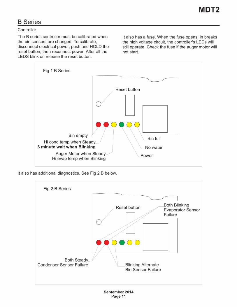
B SeriesController
The B series controller must be calibrated whenthe bin sensors are changed. To calibrate,disconnect electrical power, push and HOLD thereset button, then reconnect power. After all theLEDS blink on release the reset button.
It also has additional diagnostics. See Fig 2 B below.
MDT2
September 2014Page 11
Fig 1 B Series
Bin fullBin empty
Reset button
Hi cond temp when Steady3 minute wait when Blinking No water
PowerAuger Motor when SteadyHi evap temp when Blinking
Fig 2 B Series
Reset button
Both SteadyCondenser Sensor Failure Blinking Alternate
Bin Sensor Failure
Both BlinkingEvaporator SensorFailure
It also has a fuse. When the fuse opens, in breaksthe high voltage circuit, the controller's LEDs willstill operate. Check the fuse if the auger motor willnot start.
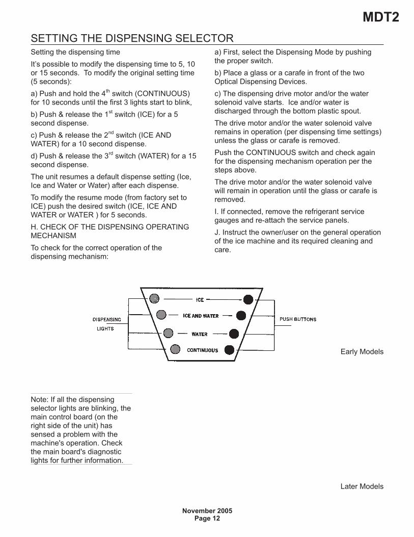
SETTING THE DISPENSING SELECTORSetting the dispensing time
It’s possible to modify the dispensing time to 5, 10or 15 seconds. To modify the original setting time(5 seconds):
a) Push and hold the 4th
switch (CONTINUOUS)for 10 seconds until the first 3 lights start to blink,
b) Push & release the 1st
switch (ICE) for a 5second dispense.
c) Push & release the 2nd
switch (ICE ANDWATER) for a 10 second dispense.
d) Push & release the 3rd
switch (WATER) for a 15second dispense.
The unit resumes a default dispense setting (Ice,Ice and Water or Water) after each dispense.
To modify the resume mode (from factory set toICE) push the desired switch (ICE, ICE ANDWATER or WATER ) for 5 seconds.
H. CHECK OF THE DISPENSING OPERATINGMECHANISM
To check for the correct operation of thedispensing mechanism:
a) First, select the Dispensing Mode by pushingthe proper switch.
b) Place a glass or a carafe in front of the twoOptical Dispensing Devices.
c) The dispensing drive motor and/or the watersolenoid valve starts. Ice and/or water isdischarged through the bottom plastic spout.
The drive motor and/or the water solenoid valveremains in operation (per dispensing time settings)unless the glass or carafe is removed.
Push the CONTINUOUS switch and check againfor the dispensing mechanism operation per thesteps above.
The drive motor and/or the water solenoid valvewill remain in operation until the glass or carafe isremoved.
I. If connected, remove the refrigerant servicegauges and re-attach the service panels.
J. Instruct the owner/user on the general operationof the ice machine and its required cleaning andcare.
MDT2
November 2005Page 12
Early Models
Later Models
Note: If all the dispensingselector lights are blinking, themain control board (on theright side of the unit) hassensed a problem with themachine's operation. Checkthe main board's diagnosticlights for further information.
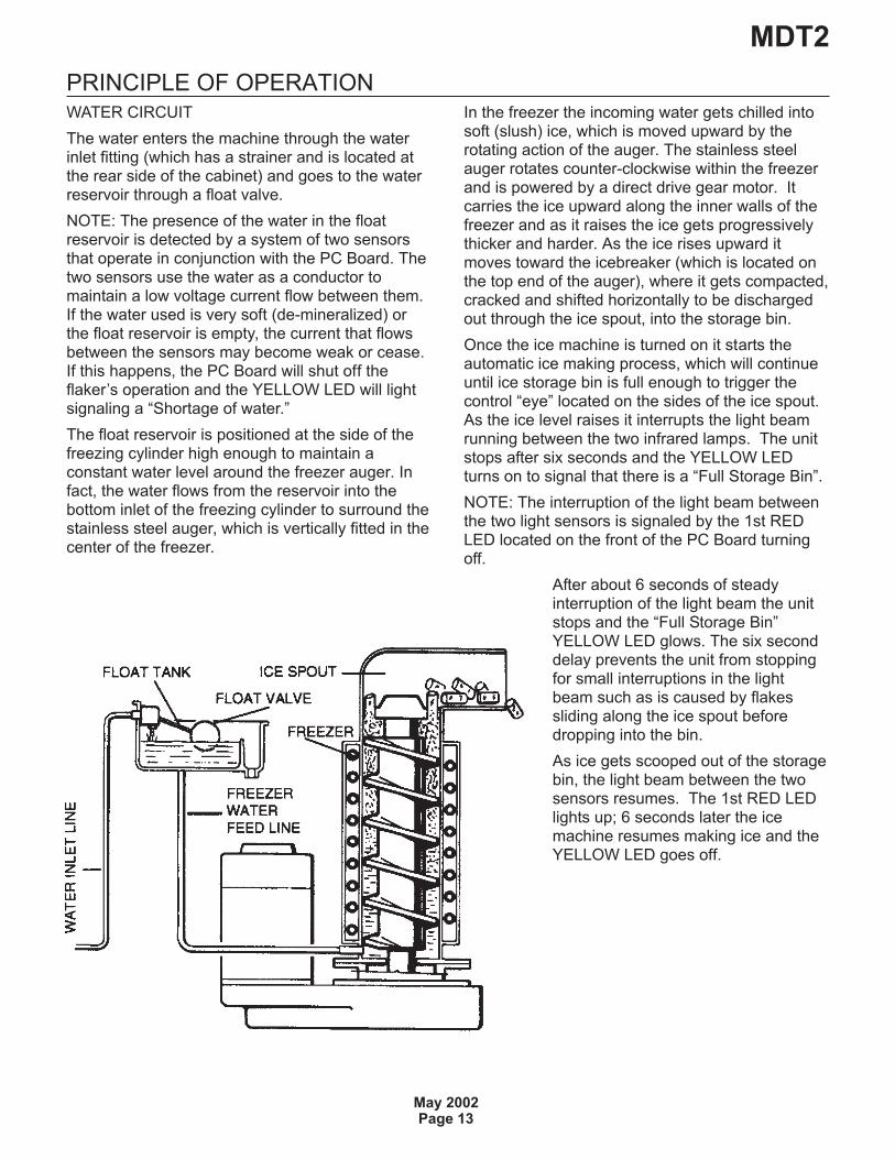
PRINCIPLE OF OPERATIONWATER CIRCUIT
The water enters the machine through the waterinlet fitting (which has a strainer and is located atthe rear side of the cabinet) and goes to the waterreservoir through a float valve.
NOTE: The presence of the water in the floatreservoir is detected by a system of two sensorsthat operate in conjunction with the PC Board. Thetwo sensors use the water as a conductor tomaintain a low voltage current flow between them.If the water used is very soft (de-mineralized) orthe float reservoir is empty, the current that flowsbetween the sensors may become weak or cease.If this happens, the PC Board will shut off theflaker’s operation and the YELLOW LED will lightsignaling a “Shortage of water.”
The float reservoir is positioned at the side of thefreezing cylinder high enough to maintain aconstant water level around the freezer auger. Infact, the water flows from the reservoir into thebottom inlet of the freezing cylinder to surround thestainless steel auger, which is vertically fitted in thecenter of the freezer.
In the freezer the incoming water gets chilled intosoft (slush) ice, which is moved upward by therotating action of the auger. The stainless steelauger rotates counter-clockwise within the freezerand is powered by a direct drive gear motor. Itcarries the ice upward along the inner walls of thefreezer and as it raises the ice gets progressivelythicker and harder. As the ice rises upward itmoves toward the icebreaker (which is located onthe top end of the auger), where it gets compacted,cracked and shifted horizontally to be dischargedout through the ice spout, into the storage bin.
Once the ice machine is turned on it starts theautomatic ice making process, which will continueuntil ice storage bin is full enough to trigger thecontrol “eye” located on the sides of the ice spout.As the ice level raises it interrupts the light beamrunning between the two infrared lamps. The unitstops after six seconds and the YELLOW LEDturns on to signal that there is a “Full Storage Bin”.
NOTE: The interruption of the light beam betweenthe two light sensors is signaled by the 1st REDLED located on the front of the PC Board turningoff.
After about 6 seconds of steadyinterruption of the light beam the unitstops and the “Full Storage Bin”YELLOW LED glows. The six seconddelay prevents the unit from stoppingfor small interruptions in the lightbeam such as is caused by flakessliding along the ice spout beforedropping into the bin.
As ice gets scooped out of the storagebin, the light beam between the twosensors resumes. The 1st RED LEDlights up; 6 seconds later the icemachine resumes making ice and theYELLOW LED goes off.
MDT2
May 2002Page 13
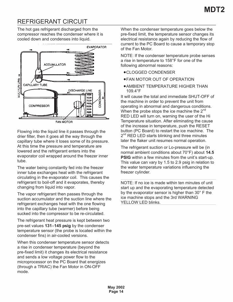
REFRIGERANT CIRCUITThe hot gas refrigerant discharged from thecompressor reaches the condenser where it iscooled down and condenses into liquid.
Flowing into the liquid line it passes through thedrier filter, then it goes all the way through thecapillary tube where it loses some of its pressure.At this time the pressure and temperature arelowered and the refrigerant enters into theevaporator coil wrapped around the freezer innertube.
The water being constantly fed into the freezerinner tube exchanges heat with the refrigerantcirculating in the evaporator coil. This causes therefrigerant to boil-off and it evaporates, therebychanging from liquid into vapor.
The vapor refrigerant then passes through thesuction accumulator and the suction line where therefrigerant exchanges heat with the one flowinginto the capillary tube (warmer) before beingsucked into the compressor to be re-circulated.
The refrigerant heat pressure is kept between two
pre-set values 131�145 psig by the condensertemperature sensor (the probe is located within thecondenser fins) in air-cooled versions.
When this condenser temperature sensor detectsa rise in condenser temperature (beyond thepre-fixed limit) it changes its electrical resistanceand sends a low voltage power flow to themicroprocessor on the PC Board that energizes(through a TRIAC) the Fan Motor in ON-OFFmode.
When the condenser temperature goes below thepre-fixed limit, the temperature sensor changes itselectrical resistance again by reducing the flow ofcurrent to the PC Board to cause a temporary stopof the Fan Motor.
NOTE: If the condenser temperature probe sensesa rise in temperature to 158°F for one of thefollowing abnormal reasons:
�CLOGGED CONDENSER
�FAN MOTOR OUT OF OPERATION
�AMBIENT TEMPERATURE HIGHER THAN109.4°F
It will cause the total and immediate SHUT-OFF ofthe machine in order to prevent the unit fromoperating in abnormal and dangerous conditions.When the probe stops the ice machine the 2
nd
RED LED will turn on, warning the user of the HiTemperature situation. After eliminating the causeof the increase in temperature, push the RESETbutton (PC Board) to restart the ice machine. The2
ndRED LED starts blinking and three minutes
later the flaker unit resumes normal operation.
The refrigerant suction or Lo-pressure will be (in
normal ambient conditions about 70°F) about 14.5
PSIG within a few minutes from the unit’s start-up.This value can vary by 1.5 to 2.9 psig in relation tothe water temperature variations influencing thefreezer cylinder.
NOTE: If no ice is made within ten minutes of unitstart up and the evaporating temperature detectedby the evaporator sensor is higher than 30° F theice machine stops and the 3rd WARNINGYELLOW LED blinks.
MDT2
May 2002Page 14

MECHANICAL SYSTEMThe mechanical system of the SCOTSMANNugget Ice Dispenser consists of a gear motorassembly that drives (through a ratchet coupling) aworn shaft or auger placed on its vertical axiswithin the freezing cylinder.
The gear motor is made of a single-phase electricmotor with a permanent capacitor. This motor isdirectly fitted in the gear case through which itdrives – in a counter clockwise rotation at a speedof 9.5 rpm – the freezer auger linked to it by theratchet coupling.
NOTE If the gear motor rotates in the wrongdirection (counter-clockwise) or is not rotating at allthe unit will stop immediately and the 3RDWARNING YELLOW LED will turn on showing theintervention of the Electromagnetic Safety Device -based on Hall Effect principle.
After diagnosing and eliminating the source of thefailure, restart the unit by pressing the RESETbutton or turn the power switch OFF and ON (Fig.7).
The RED LED will start blinking and after 3minutes the ice machine will resume normaloperations by running first the gear motor and thenthe compressor.
When the gear motor rotating speed is slowedbelow 1300 rpm - normal speed is 1400 rpm - theElectromagnetic Safety Device transmits anelectrical signal to the MICROPROCESSOR tostop the unit operation immediately (just as it doesfor the wrong rotation) and the 3rd YELLOWWARNING LED turns on. This is done to avoid
overloading the electrical and mechanicalcomponents of the entire Drive System and extendtheir durability.
NOTE: After diagnosing and eliminating the sourceof the gear motor slow rotation, restart the unit bypushing the RESET button to or turning the powerline main switch OFF and ON.
NOTE: Any time the machine stops with a problemthe front 4 LED’s start to blink.
REFRIGERANT METERING DEVICE:
�Capillary tube
OPERATING PRESSURES
(With 70°F ambient temperature)
�Discharge pressure: 130 to 145 psig
�Suction pressure: 14.5 psig
�REFRIGERANT CHARGE (R 134 A): 13 oz.
NOTE: Before charging the refrigerant systemalways check the type of refrigerant and quantityas specified on the individual ice machine dataplate.
The refrigerant charges indicated are relatives toaverages operating conditions.
MDT2
May 2003Page 15
Fig 7
Bin empty
Reset button
PowerAuger Motor when Steady
COMPONENT DESCRIPTIONA. EVAPORATOR TEMPERATURE SENSOR -BLUE 2 POLE CONNECTOR - MANUAL RESET
The evaporator sensor probe is inserted into itstube well, which is welded on the evaporator outletline. It detects the temperature of the refrigerant onthe way out of the evaporator and signals it bysupplying a low voltage current flow to the PCBoard microprocessor. According to the currentreceived, the microprocessor lets the ice machineto continue its operations or not. If within 10minutes of startup the evaporating temperaturedoes not go below 30°F the evaporator sensorsignals the microprocessor to stop the unitoperation immediately and causes the 3rdWARNING YELLOW LED to blink.
B. WATER LEVEL SENSOR - RED TWO POLECONNECTOR – AUTOMATIC RESET
This sensor system consists of two small stainlesssteel rods vertically fitted on the inner face of thereservoir cover and electrically connected to thelow voltage circuit of the PC Board. When thecover of the reservoir is positioned properly the tipsof both rods dip into the reservoir water and signalits presence by supplying power to the PC Board.
NOTE: In the event of shortage of water in thereservoir or if the water used is too soft(de-mineralized) to cause greater resistance to thecurrent flow (conductivity lower than 30mS) thissensor system causes the machine to shutoff toprotect it from running with an interrupted orinadequate water supply.
When this happens the 5th YELLOW LED will turnon warn that the ice machine is off and why.
C. CONDENSER TEMPERATURE SENSOR -BLACK TWO POLE CONNECTOR –MANUALRESET
The condenser temperature sensor probe (locatedwithin the condenser fins) detects condensertemperature variations and signals them bysupplying current, at low voltage, to the PCBOARD.
Current to the microprocessor on the PC Boardvaries and as it does the microprocessor supplies,through a TRIAC, power at a high voltage to thefan motor so that it can cool the condenser andreduce its temperature.
If the temperature rises to 158°F or above thecurrent sent to the microprocessor causes themachine to cease operation and turns on the 2ndRED WARNING LED.
NOTE: After fixing the problem that caused thehigh condenser temperature, press the RESETbutton or turn the power line main disconnectswitch OFF and ON to restart the unit after the shutdown.
The fan motor will cycle on an off to maintain thedischarge pressure.
D. GEAR MOTOR ROTATION AND SPEEDSENSOR - RED FOUR POLE CONNECTOR -MANUAL RESET
This safety device is housed on top of the DriveMotor and detects - based on the Hall Effectprinciple - the rotating speed and rotating directionof the drive Motor. Should the rotating speed dropbelow 1300 rpm the magnitude measured by thisdevice signals the microprocessor to stop the unitand turns on the 3rd YELLOW LED. The samereaction occurs when the drive motor rotates in thewrong direction (counterclockwise) or it doesn’trotate at all.
NOTE: After diagnosing and eliminating theproblem that caused the intervention of the safetydevice, press the RESET button or turn the powerline main disconnect switch OFF and ON to restartthe unit after the shut down.
MDT2
May 2002Page 16
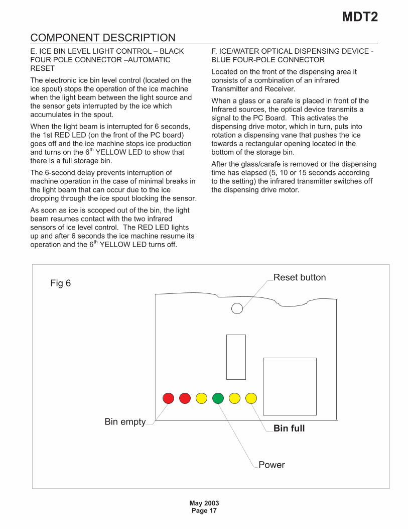
COMPONENT DESCRIPTIONE. ICE BIN LEVEL LIGHT CONTROL – BLACKFOUR POLE CONNECTOR –AUTOMATICRESET
The electronic ice bin level control (located on theice spout) stops the operation of the ice machinewhen the light beam between the light source andthe sensor gets interrupted by the ice whichaccumulates in the spout.
When the light beam is interrupted for 6 seconds,the 1st RED LED (on the front of the PC board)goes off and the ice machine stops ice productionand turns on the 6
thYELLOW LED to show that
there is a full storage bin.
The 6-second delay prevents interruption ofmachine operation in the case of minimal breaks inthe light beam that can occur due to the icedropping through the ice spout blocking the sensor.
As soon as ice is scooped out of the bin, the lightbeam resumes contact with the two infraredsensors of ice level control. The RED LED lightsup and after 6 seconds the ice machine resume itsoperation and the 6
thYELLOW LED turns off.
F. ICE/WATER OPTICAL DISPENSING DEVICE -BLUE FOUR-POLE CONNECTOR
Located on the front of the dispensing area itconsists of a combination of an infraredTransmitter and Receiver.
When a glass or a carafe is placed in front of theInfrared sources, the optical device transmits asignal to the PC Board. This activates thedispensing drive motor, which in turn, puts intorotation a dispensing vane that pushes the icetowards a rectangular opening located in thebottom of the storage bin.
After the glass/carafe is removed or the dispensingtime has elapsed (5, 10 or 15 seconds accordingto the setting) the infrared transmitter switches offthe dispensing drive motor.
MDT2
May 2003Page 17
Fig 6
Bin fullBin empty
Reset button
Power
COMPONENT DESCRIPTION
G. FRONT DISPENSING SELECTOR/DISPLAY -
BLACK SIX-POLE CONNECTOR
Placed in the upper front part of the dispensingarea it is used to select (varies by machine model):
a) Ice (first switch)
or
a) Ice (first switch)
b) Ice and water (second switch)
c) Water - not chilled - (third switch)
It is also possible to set up for “continuous”dispensing operation just by pushing the fourthswitch before or after the selection of thedispensed product.
Once completed the dispensing selector/displayresumes its original dispensing setting mode.
NOTE: It is possible to modify the original resumemode (default) by pushing the correspondingswitch for 5 seconds (all machines are factory setto the ICE dispensing mode).
It is also possible to modify the dispensing timecontrolled by the PC Board to 5, 10 or 15 secondsby:
a) Push and hold the 4th switch “continuous” forapproximately 10 seconds till the first 3 lights startto blink
b) Pushing the 1st switch (ICE) is equivalent to 5seconds.
Pushing the 2nd switch (ICE+WATER) isequivalent to 10 seconds.
Pushing the 3rd switch (WATER) is equivalent to15 seconds.
H. PC BOARD (Data processor)
The PC BOARD (in a plastic box on the right sideof the unit) consists of two separated printed circuitboards; one at high voltage and the other at lowvoltage, protected by three fuses, integrated with aRESET button. It also consists of six aligned LEDSmonitoring machine operation, input terminals forthe leads of the sensor probes as well as input andoutput terminals for the leads of the ice machineelectrical wires.
The PC BOARD is the brain of the system. Itrelays through its microprocessor, the signalsreceived from the sensors to control the operationof the different electrical components of the icemachine (compressor, gear motor, etc.) as well asthe dispensing of the ice and water.
The six LEDS on the front of the PC BOARDindicate the following:
RED LIGHT
- Empty storage bin
RED LIGHT
ON all the time
- Unit shut-off due to a Too high-condensingtemperature > 158°F
Blinking
- 3 minutes start up delay time
YELLOW LIGHT
ON all the time
- Unit shut-off due to the wrong rotation direction ofgear motor
- Unit shut-off due to the too lo speed of gearmotor
Blinking
- Unit shut-off due to a Too high-evaporating temp.
>-30°F after 10 min of operation
GREEN LIGHT
- Unit under electrical power
YELLOW LIGHT
- Unit shut-off due to a too lo-water level into floattank
YELLOW LIGHT
- Unit shut-off at full storage bin
BLINKING – 3 MINUTE STAND-BY PERIOD
MDT2
May 2002Page 18

COMPONENT DESCRIPTIONI. FLOAT RESERVOIR
The float reservoir consists of a plastic water panwhich has a float valve with a set screw on it. Thefloat valve modulates the incoming water flow tomaintain a constant water level in the reservoir thatcorresponds to the one in the freezing cylinder toensure proper ice formation and fluidity.
On the inside of the reservoir cover are two waterlevel sensors that detect the presence or shortageof water in the reservoir.
NOTE: It is very important to make sure that thecover on the reservoir is seated properly to enablethe sensors to efficiently control the water level toavoid undue shutoff.
J. FREEZING CYLINDER (EVAPORATOR)
The freezing cylinder is made of a stainless steelvertical tube. The cooling coil is wrapped aroundits exterior with the evaporating chamber. In itsinterior is the auger which rotates on a vertical axisthat is kept aligned by the top and bottombearings. A water seal system is located in thebottom part of the freezer and the ice breaker isfitted on top end.
The water constantly flows into the cylinder bottomand it freezes into ice when it comes into contactwith the cylinder inner walls. The ice is then liftedup by the rotating auger, compacted and forced outby the icebreaker.
K. ICE BREAKER
The icebreaker is made up of several rectangularopenings that the ice is forced to pass through. Byundergoing this process, the ice loses its excess ofwater content and drops into the bin in hard drybits of ice.
The icebreaker houses the top bearing, which ismade of two roller bearings, positioned towithstand the auger axial and radial loads. Thisbearing is lubricated with a food-grade,water-resistant grease.
NOTE: Check the conditions of both the lubricantgrease and the bearings every six months.
L. DRIVE GEAR MOTOR
This motor reducer is made of a single-phaseelectric motor with a permanent capacitor directlyfitted on a gearbox.
The drive motor rotor is kept aligned on its verticalaxis by two permanently lubricated ball bearings.
The gear case contains a train of three spur gears,the first of which is fiber to limit the noise level. Allthree gears are encased in case bearings and arecovered by lubricant grease (MOBILPLEX IP 44).
Two seal rings, one fitted on the rotor shaft and theother on the output shaft, keep the gear casesealed. However, the interior can be inspectedand serviced by unbolting the two halves of thealuminum gear case housing.
The gear reducer output shaft is connected to thefreezer auger by a ratchet coupling which is madeof two toothed halves that engage only if turned inthe correct direction (counter-clockwise).
M. FAN MOTOR (Air cooled version)
The fan motor is controlled through the PC Boardand the TRIAC by the condenser temperaturesensor. Normally it operates to draw cooling airthrough the condenser fins.
In a cold ambient situation, the fan motor can runintermittently as the condenser pressure must bekept between two corresponding head pressurevalues.
N. ICE DISPENSER DRIVE MOTOR
Located on the upper side of the storage bin, itturns the dispensing vane by a milled shaft insidethe round storage bin.
By rotating, the dispensing vane pushes the icetowards the bottom rectangular opening to forcethe nugget ice to go through the bottom outletspout.
O. STORAGE BIN
The storage bin is located in the front of the icemachine. It main purpose is to store the cubeletice produced by the evaporator until it reaches itsmaximum level. In its bottom is placed the icespout as well as the water drain hole.
Inside the ice spout opening is the water outlettube connected to the solenoid valve.
P. DISPENSING WATER SOLENOID VALVE
Energized and controlled by the PC Board, itallows a metered quantity of not chilled water to bedispensed through the same opening of the ice.
MDT2
May 2003Page 19
MDT2
May 2003Page 20
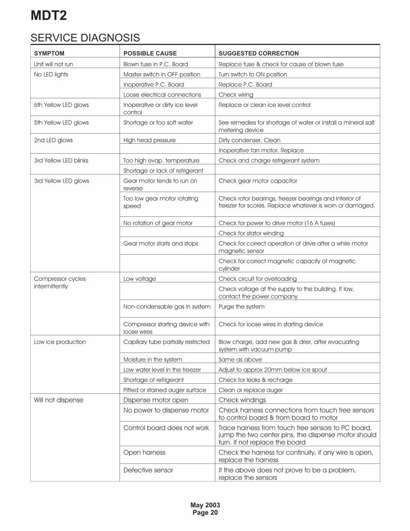
SERVICE DIAGNOSIS
SYMPTOM POSSIBLE CAUSE SUGGESTED CORRECTION
Unit will not run Blown fuse in P.C. Board Replace fuse & check for cause of blown fuse
No LED lights Master switch in OFF position Turn switch to ON position
Inoperative P.C. Board Replace P.C. Board
Loose electrical connections Check wiring
6th Yellow LED glows Inoperative or dirty ice level
control
Replace or clean ice level control
5th Yellow LED glows Shortage or too soft water See remedies for shortage of water or install a mineral salt
metering device
2nd LED glows High head pressure Dirty condenser. Clean
Inoperative fan motor. Replace
3rd Yellow LED blinks Too high evap. temperature Check and charge refrigerant system
Shortage or lack of refrigerant
3rd Yellow LED glows Gear motor tends to run on
reverse
Check gear motor capacitor
Too low gear motor rotating
speed
Check rotor bearings, freezer bearings and interior offreezer for scores. Replace whatever is worn or damaged.
No rotation of gear motor Check for power to drive motor (16 A fuses)
Check for stator winding
Gear motor starts and stops Check for correct operation of drive after a while motor
magnetic sensor
Check for correct magnetic capacity of magnetic
cylinder
Compressor cycles
intermittently
Low voltage Check circuit for overloading
Check voltage at the supply to the building. If low,
contact the power company
Non-condensable gas in system Purge the system
Compressor starting device with
loose wires
Check for loose wires in starting device
Low ice production Capillary tube partially restricted Blow charge, add new gas & drier, after evacuating
system with vacuum pump
Moisture in the system Same as above
Low water level in the freezer Adjust to approx 20mm below ice spout
Shortage of refrigerant Check for leaks & recharge
Pitted or stained auger surface Clean or replace auger
Will not dispense Dispense motor open Check windings
No power to dispense motor Check harness connections from touch free sensorsto control board & from board to motor
Control board does not work Trace harness from touch free sensors to PC board,jump the two center pins, the dispense motor shouldturn. If not replace the board
Open harness Check the harness for continuity, if any wire is open,replace the harness
Defective sensor If the above does not prove to be a problem,replace the sensors
SERVICE DIAGNOSIS
MDT2
May 2003Page 21
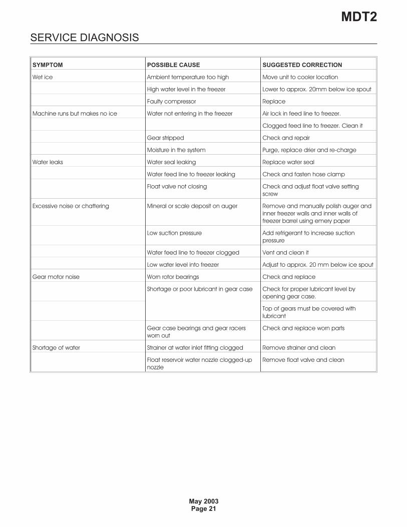
SYMPTOM POSSIBLE CAUSE SUGGESTED CORRECTION
Wet ice Ambient temperature too high Move unit to cooler location
High water level in the freezer Lower to approx. 20mm below ice spout
Faulty compressor Replace
Machine runs but makes no ice Water not entering in the freezer Air lock in feed line to freezer.
Clogged feed line to freezer. Clean it
Gear stripped Check and repair
Moisture in the system Purge, replace drier and re-charge
Water leaks Water seal leaking Replace water seal
Water feed line to freezer leaking Check and fasten hose clamp
Float valve not closing Check and adjust float valve setting
screw
Excessive noise or chattering Mineral or scale deposit on auger Remove and manually polish auger and
inner freezer walls and inner walls of
freezer barrel using emery paper
Low suction pressure Add refrigerant to increase suction
pressure
Water feed line to freezer clogged Vent and clean it
Low water level into freezer Adjust to approx. 20 mm below ice spout
Gear motor noise Worn rotor bearings Check and replace
Shortage or poor lubricant in gear case Check for proper lubricant level by
opening gear case.
Top of gears must be covered with
lubricant
Gear case bearings and gear racers
worn out
Check and replace worn parts
Shortage of water Strainer at water inlet fitting clogged Remove strainer and clean
Float reservoir water nozzle clogged-up
nozzle
Remove float valve and clean
MAINTENANCE AND CLEANING INSTRUCTIONA. GENERAL
The times and the procedures for maintenanceand cleaning are given as guides and are not to beconstrued as absolute or invariable. Cleaningespecially will vary depending upon local waterand ambient conditions and the ice volumeproduced. Each ice machine must be maintainedindividually, in accordance with its particularlocation requirements.
B. ice machine
The following maintenance should be scheduled atleast two times per year on these ice machines:
1. Check and clean the water line strainer or filter.
2. Remove the cover from the float reservoir – becareful to not damage the two water sensors –anddepress the float to make sure that a full stream ofwater enters the reservoir.
3. Check that the ice machine is level.
4. Check that the water level in the water reservoiris below the overflow but high enough that it doesnot run out of the spout opening.
NOTE: The float must stop the incoming water flowwhen the rubber housed in the setting screw isperpendicular to the water nozzle.
5. Clean the water system, water reservoir and theinterior of freezing cylinder using a solution ofSCOTSMAN Ice Machine Cleaner. Refer tosection C. CLEANING INSTRUCTIONS OFWATER SYSTEM for cleaning procedures andafter cleaning will indicate frequency andprocedure to be followed in local areas.
NOTE: Cleaning requirements vary according tothe local water conditions and individual useroperation.
6. If required, polish the two sensor rods securedto the float reservoir cover. Heavy scale sedimenton them can be removed with the help of a bit ofSCOTSMAN Cleaner plain.
7. With the ice machine and fan motor OFF cleancondenser using vacuum cleaner, whiskbroom ornon-metallic brush taking care to do not damagethe condenser temperature sensor.
8. Check for water leaks and tighten drain lineconnections. Pour water into the sink to be surethat drain line is open and clear.
9. Check the ice level control sensor to testshut-off. Put your hand between the light source
and the receiver on the upper side of the storagebin to cut off the light beam for at least 6 seconds.
This should cause the 1st RED LED on the front ofthe PC board to turn off and, 6 seconds later theice machine will cease operation and the 6thYELLOW LED will turn on. Once you remove yourhand the ice machine should resume normaloperation within a few seconds.
NOTE: The ice level control uses a device thatsenses light, therefore they must be kept cleanenough so they can “see”.
Every month clean/wipe the sensing “eyes” with aclean soft cloth.
10. Check for refrigerant leaks and for proper frostline, approx. 8 inches from the compressor.
When in doubt of refrigerant charge, connectrefrigerant gauges to corresponding Schrädervalves and check for correct refrigerant pressures.(See Operating Pressure on page 19 of thismanual).
11. Check that fan blades move freely and are nottouching any surfaces.
12. Remove the ice spout cover, loosen the boltsecuring the casting ice sweep and remove it; theninspect the top bearing. Wipe away existinggrease and apply a coating of food gradewaterproof grease (P/N F263612-00).
NOTE: Use of food-grade, waterproof grease tolubricate the top bearing is recommended.
13. Turn the ice-dispensing spout and remove it.Wash and sanitize it.
14. Remove the sink grill for washing andsanitizing.
MDT2
May 2003Page 22
CLEANING INSTRUCTIONS OF WATER SYSTEM1. Switch OFF the power supply to the MDT2.
2. Remove the top panel and the top cover of thestorage bin with the dispensing drive motor.
3. Remove all ice stored in the bin to prevent itfrom getting contaminated with the cleaningsolution.
4. Close the water shutoff valve on water line.
5. Remove the left side panel to gain access to thewater reservoir.
6. Remove the float reservoir cover and jump thetwo water level sensors with a piece of copperwire.
7. Remove the right service panel and loosen thedrain plug from the water purge tube to drain all ofwater our of the freezer. Then re-plug the purgetube.
CLEANING
8. Prepare the cleaning solution by diluting it in aplastic container with 2.1 quarts (2 liters) of warmwater (113°-122°F) with 7 ounces (0.2 liters) ofSCOTSMAN Ice Machine Cleaner.
WARNING: SCOTSMAN Ice Machine Cleanercontains Phosphoric and Hydroxyacetic acids.These compounds are corrosive and may causeburns if swallowed, DO NOT induce vomiting.Give large amounts of water or milk and call aPhysician immediately. In case of external contact,flush with water. KEEP OUT OF THE REACH OFCHILDREN
9. Pour the cleaning solution into the waterreservoir until it reaches the proper level.
10. After 15 minutes switch ON the Master switchto start the unit.
11. Wait till the machine starts to discharge ice,then continue to slowly pour the cleaning solutioninto the water reservoir taking care to maintain thelevel just below the overflow.
NOTE: The ice made with the cleaning solution isslushy and colored. It may also loose fluiditycreating some resistance in being elevated andextruded; this situation can be heard by thecreaking noise made by the ice.
If this should occur it is recommended that youstop the ice machine for few minutes in order toallow the ice in the freezer to partially melt.
12. When all of the cleaning solution has beenused up, open the water shutoff valve to allow newfresh water to flow into the reservoir. Let the unitcontinue to run until the ice resumes the normalcolor and hardness.
13. Stop the ice machine and pour warm water onthe ice deposited into the storage bin to melt it.
NOTE: DO NOT use ice produced with thecleaning solution. Be sure none remains in the bin.
SANITATION
14. Pour into the water reservoir locally approvedsanitizer mixed according to the directions for thatsanitizer. A possible saniziter can be obtained bymixing 1 ounce of liquid household bleach with 2gallons of warm water.
15. Leave the unit running for approx 10 minutesthen remove the copper wire used to jump the twosensors for the water level and place the coverback on the float reservoir.
NOTE: DO NOT use ice produced with thesanitizing solution.
16. With a sponge moistened with a sanitizingsolution, wipe clean all bin interior surfaces.
REMEMBER: To prevent the accumulation ofundesirable bacteria it is necessary to sanitize theinterior of the storage bin with an anti-algaedisinfectant solution.
MDT2
February 2012Page 23
REMOVAL AND REPLACEMENT
Bearings, Auger, Water Seal
Note: Metric tools are required for this procedure.
Disconnect electrical power.
1. Remove all panels and the sink assembly.
2. Remove the spout cover.
3. Use a 17mm socket to remove the top boltholding the ice sweep to the auger.
4. Use a 13mm socket to remove the four boltsholding the breaker to the auger.
5. Lift up to remove breaker.
To remove top bearing:
6. Remove snap ring from the top of the breaker.
7. Turn breaker over and using a ¾” punch or bolt,tap the bearing out from the bottom.
To remove auger:
8. After removing breaker, pull up on the auger toremove it.
To remove water seal or bottom bearing.
9. Remove bin cover.
10. Disconnect drain and water line from bin.
11. Remove nut holding bin to chassis.
12. Pull bin out of machine.
13. Remove screws holding air deflector to chassisand pull deflector out of the unit.
14. Remove screws holding reservoir to bulkheadpanel.
15. Remove screws holding bulkhead panel tochassis frame, push panel back several inches.
16. Use a 13 mm open end or box wrench andremove the three bolts holding the adapter stand tothe evaporator.
17. Lift evaporator up and off the stand.
18. Tap water seal and bottom bearing out of theevaporator from the top down.
To remove gear reducer.
1. Disconnect power leads and sensor wires frommotor.
2. Perform steps to remove bottom bearing.
3. Use a 10 mm socket or box wrench to removethe 5 bolts holding the gear reducer to the unit.
4. Remove the gear reducer from the unit.
Reverse all individual sections to reassemble
that section except for the top bearing and
water seal. See the next page.
MDT2
May 2003Page 24
TOP BEARING REPLACEMENT
Replacement of the top bearing
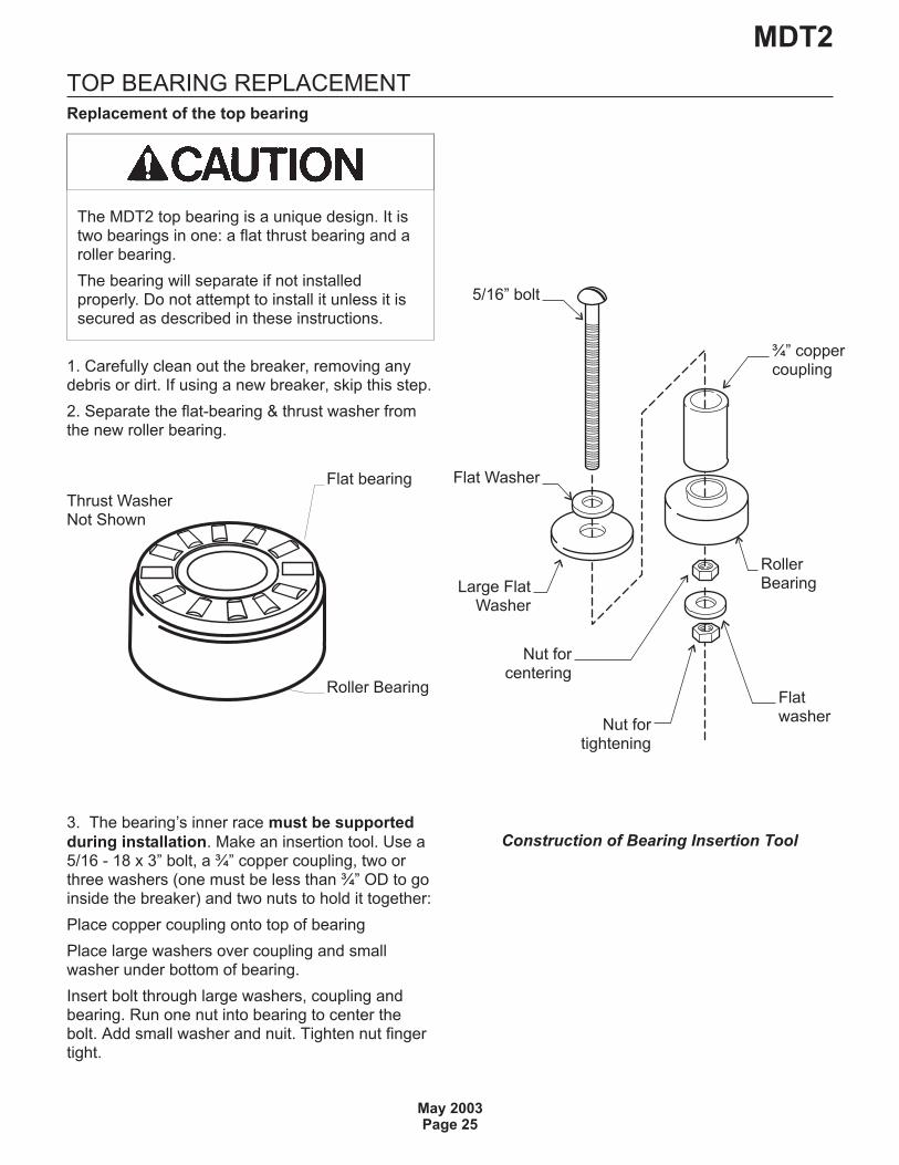
1. Carefully clean out the breaker, removing anydebris or dirt. If using a new breaker, skip this step.
2. Separate the flat-bearing & thrust washer fromthe new roller bearing.
3. The bearing’s inner race must be supported
during installation. Make an insertion tool. Use a5/16 - 18 x 3” bolt, a ¾” copper coupling, two orthree washers (one must be less than ¾” OD to goinside the breaker) and two nuts to hold it together:
Place copper coupling onto top of bearing
Place large washers over coupling and smallwasher under bottom of bearing.
Insert bolt through large washers, coupling andbearing. Run one nut into bearing to center thebolt. Add small washer and nuit. Tighten nut fingertight.
MDT2
May 2003Page 25
Flat bearing
Roller Bearing
Thrust WasherNot Shown
Construction of Bearing Insertion Tool
5/16” bolt
Flat Washer
¾” coppercoupling
RollerBearing
Nut forcentering
Flatwasher
Nut fortightening
Large FlatWasher
The MDT2 top bearing is a unique design. It istwo bearings in one: a flat thrust bearing and aroller bearing.
The bearing will separate if not installedproperly. Do not attempt to install it unless it issecured as described in these instructions.
BEARING REPLACEMENT - CONTINUED
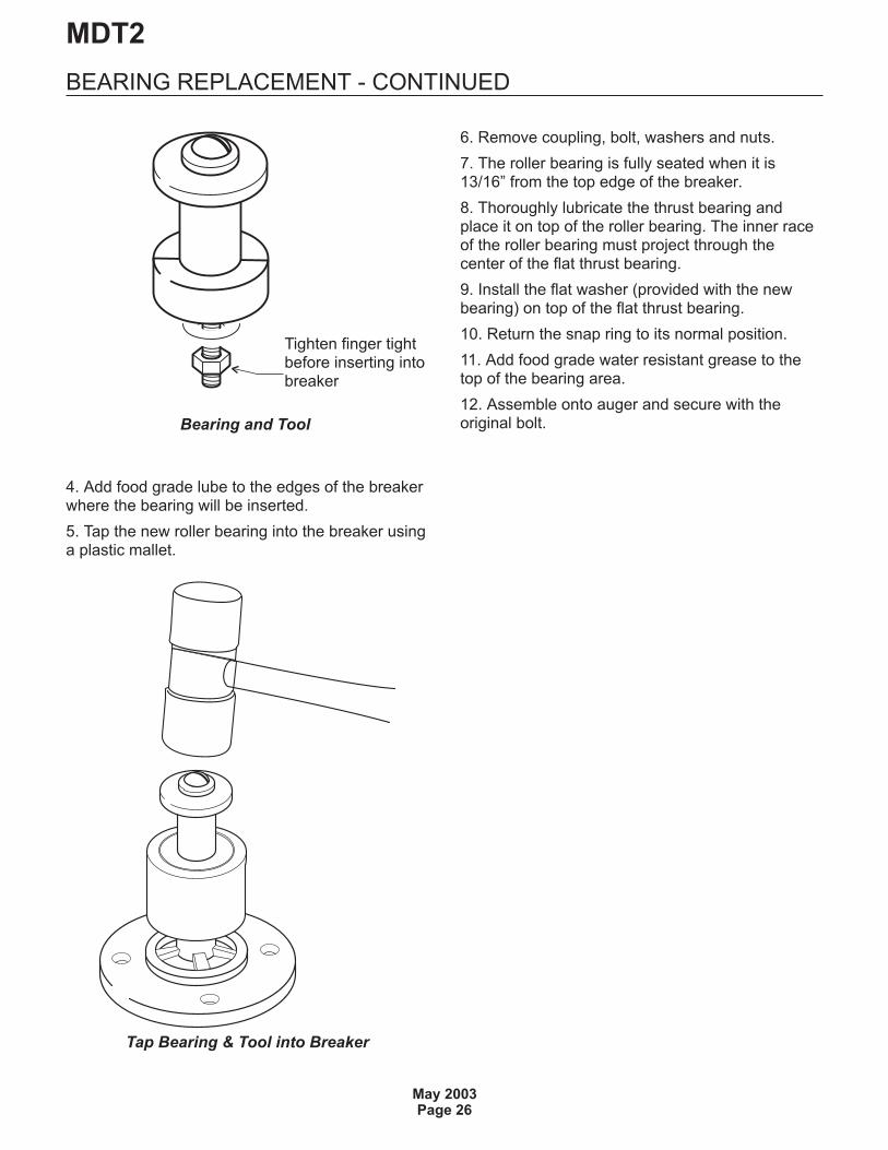
4. Add food grade lube to the edges of the breakerwhere the bearing will be inserted.
5. Tap the new roller bearing into the breaker usinga plastic mallet.
6. Remove coupling, bolt, washers and nuts.
7. The roller bearing is fully seated when it is13/16” from the top edge of the breaker.
8. Thoroughly lubricate the thrust bearing andplace it on top of the roller bearing. The inner raceof the roller bearing must project through thecenter of the flat thrust bearing.
9. Install the flat washer (provided with the newbearing) on top of the flat thrust bearing.
10. Return the snap ring to its normal position.
11. Add food grade water resistant grease to thetop of the bearing area.
12. Assemble onto auger and secure with theoriginal bolt.
MDT2
May 2003Page 26
Tap Bearing & Tool into Breaker
Bearing and Tool
Tighten finger tightbefore inserting intobreaker
WATER SEAL
Stationary Half
1. Insert new water seal into bottom of evaporator.
2. Insert new bearing under the water seal, push ortap both in until the bottom of the bearing is flush
3. Assemble adapter to evaporator. Tightening themounting bolts will correctly position the bottombearing and bottom seal.
Rotating Half
1. Remove old rotating half from the auger. Cleanthe mounting area.
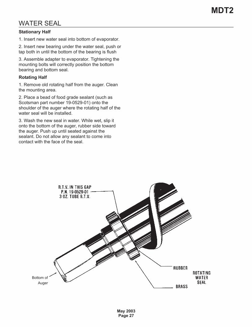
2. Place a bead of food grade sealant (such asScotsman part number 19-0529-01) onto theshoulder of the auger where the rotating half of thewater seal will be installed.
3. Wash the new seal in water. While wet, slip itonto the bottom of the auger, rubber side towardthe auger. Push up until seated against thesealant. Do not allow any sealant to come intocontact with the face of the seal.
MDT2
May 2003Page 27
Bottom of
Auger