mbw973-sf6 manual e v3.1
TRANSCRIPT
SF6 Analyzer 973
Operation Manual Version 973-SF6
V3.1
MBW Calibration Ltd. Seminarstrasse 57
CH-5430 Wettingen / Switzerland +41 56 437 28 30 Phone
+41 56 437 28 40 Fax [email protected] www.mbw.ch

MBW973-SF6_MANUAL_E_V3.1 i
Table of Contents
TABLE OF CONTENTS ...................................................................................... I
GENERAL .......................................................................................................... 1
SHORT DESCRIPTION ...................................................................................... 3
OPERATION....................................................................................................... 5 Front Panel without SO2 Option ................................................................................................. 5 Front Panel with SO2 Option ...................................................................................................... 5 Back Panel without SO2 Option ................................................................................................. 8 Back Panel with SO2 Option ...................................................................................................... 8
INITIAL SETUP ................................................................................................ 11 Preparation ............................................................................................................................... 11 Electrical Connection ............................................................................................................... 11 Connection of the Serial Interface ............................................................................................ 11 SF6 Gas Connection ................................................................................................................ 12 Evacuate the Sampling Tube ................................................................................................... 13 Evacuate the Internal Cylinder ................................................................................................. 14 SF6 Gas Connection to the Compartment ............................................................................... 15
MEASUREMENT OPTIONS ............................................................................. 17 Navigating the Menus .............................................................................................................. 17
MEASUREMENT .............................................................................................. 19 Measurement without SO2 Option ........................................................................................... 19 Termination of Measurement ................................................................................................... 20 Measurement with SO2 Option................................................................................................. 21 Termination of Measurement ................................................................................................... 22 Measuring Range Limitations .................................................................................................. 23 Alarm Messages ...................................................................................................................... 23 Measurement Aborted ............................................................................................................. 24 Measurement of Air or Nitrogen (N2) ....................................................................................... 24
DATA COLLECTION IN EXCEL ...................................................................... 25 RS-232 – USB Converter Installation ...................................................................................... 25 Data Collection over RS-232 with the Excel Protocol .............................................................. 26
SO2 MODULE ................................................................................................... 29 Replacement of SO2 Measurement Cell .................................................................................. 29 Activation of SO2 Measurement ............................................................................................... 30
ii MBW973-SF6_MANUAL_E_V3.1
TEST FUNCTIONS ........................................................................................... 32 Ice Test .................................................................................................................................... 32
ADDITIONAL SETTINGS ................................................................................. 37 Selection of Languages ........................................................................................................... 37 Selection of the indicated Parameters ..................................................................................... 38 Selection of Units ..................................................................................................................... 39 Changing Color ........................................................................................................................ 40 Storage of the Actual Settings ................................................................................................. 41 Restore Color Settings and Baud Rate .................................................................................... 42
MAINTENANCE ............................................................................................... 43 Touch Screen Calibration ........................................................................................................ 43 Mirror Cleaning ......................................................................................................................... 44 Exterior Cleaning ...................................................................................................................... 45
SPECIFICATIONS ............................................................................................ 47
MBW973-SF6_MANUAL_E_V3.1 1
General
This manual explains the function of the 973-SF6 Analyzer with and without the SO2 option. Throughout this manual the instrument will be called 973. This manual refers to instrument software versions 110525a and higher.
Should the 973 be used in any other way than that described in this user’s manual, or outside the limits described, the built-in safety pro-tection of the instrument may be compromised.
Vol SF6 % All descriptions in bold italic are related to the text on the front panel, the display and the back panel of the 973.
If you wish to use the instrument as quickly as possible, we recommend reading the chapters Initial Setup (page 11) and Measurement (page 19). Standard use of the instrument is ex-plained in these two chapters.

2 MBW973-SF6_MANUAL_E_V3.1
MBW973-SF6_MANUAL_E_V3.1 3
Short Description
Reliable Measurements in SF6 The 973 was specifically designed for measurement of humidity, SF6 purity and SO2 concentra-tion in gas insulated switchgear systems. Humidity measurement data is displayed in ppmv, ppmw and Frost/Dew Point at either gas compartment pressure or standard pressure. SF6 purity measurement is displayed directly in % Volume SF6. Both the humidity and purity measure-ments utilize accurate and reliable condensation techniques. SO2 concentration is measured with an electrochemical cell with results displayed in ppmv.
Gas Recovery and Pressure Measurement The 973 is equipped with a gas recovery system that stores the sampled gas during the meas-urement process in its internal storage cylinder. After completion of the measurement, the stored gas is pumped back into the original compartment or into another vessel. The compart-ment pressure is also measured.
Easy, Automated Measurement The 973 is equipped with a user configurable full color active matrix LCD with integrated touch screen. The 973 may be configured for measurement of Humidity and % Volume SF6 with either automatic or manually initiated Pump Back. Using the bi-directional RS-232 communications port, all measurement data may be easily transferred to a computer.
Calibration Users can easily check the 973 calibration at any time using the built-in Ice Test function, providing instant verification of system accuracy and integrity.
LCD Display with Touch Panel The 973 utilizes a full color active matrix liquid crystal display with an integral touch panel. It has a high contrast ratio and a wide viewing angle for easy readability. Data is displayed in large, easy to read fonts. Using the on screen function and menu keys, you can easily configure each line of the display and navigate the menus.
Versions equipped with the SO2 option will have alternative display and data line formats. Please refer to page 21 for further information on the measurement of SO2 concentration.
Connect and Go The system is supplied ready for immediate use.
973-SF6 with Standard Accessories • Transport Case • 6 m Stainless Steel armored PTFE tubing • SF6 coupling DN20 and DN8 • 3 m RS-232 cable incl. USB adapter with USB cable • 2.5 m power cable • Operation Manual • CD-ROM

4 MBW973-SF6_MANUAL_E_V3.1
MBW973-SF6_MANUAL_E_V3.1 5
Operation
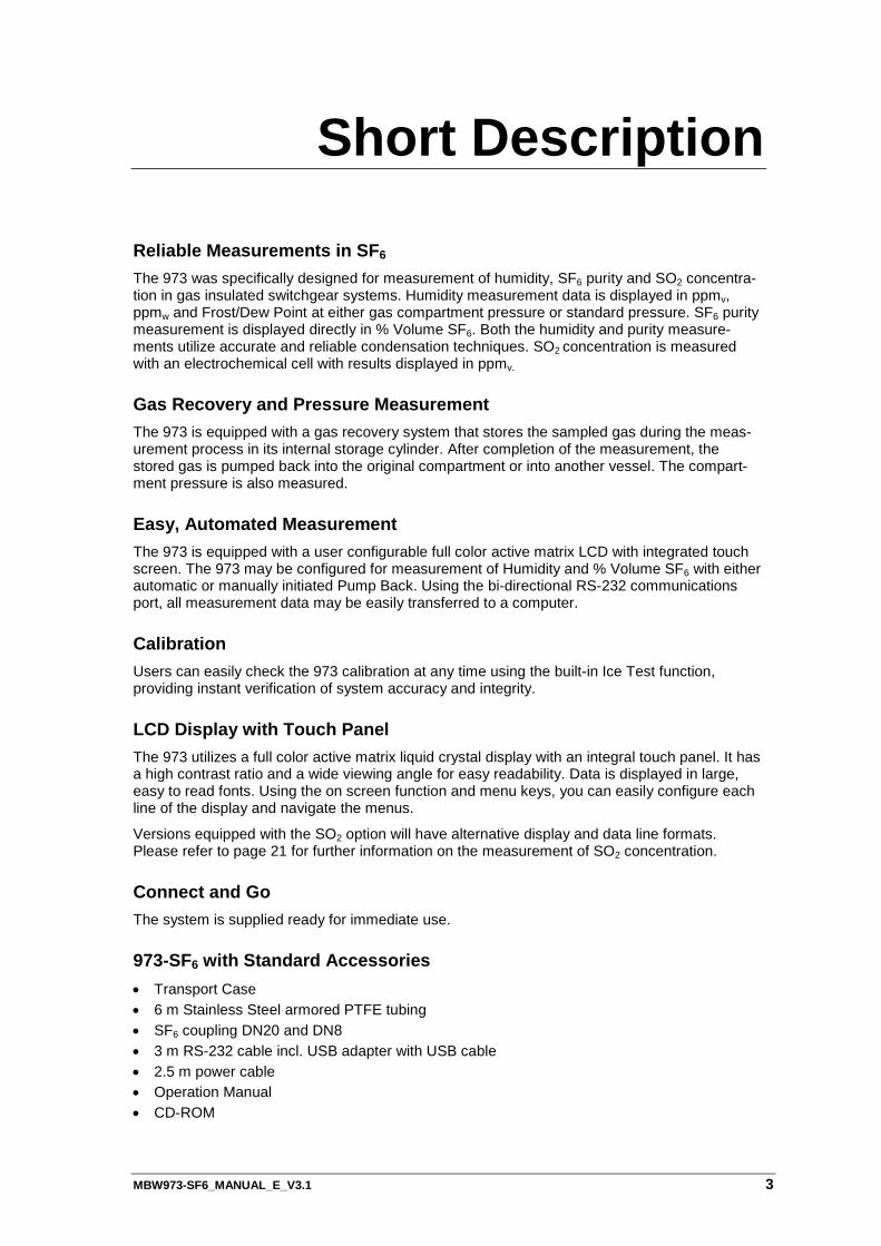
Front Panel without SO2 Option
Front Panel with SO2 Option
Status of Measurement Measuring Head
Keypad Menu Keys
Internal Cylinder Capacity
Fixed Function Keys
Touch Screen
Data Lines
6 MBW973-SF6_MANUAL_E_V3.1
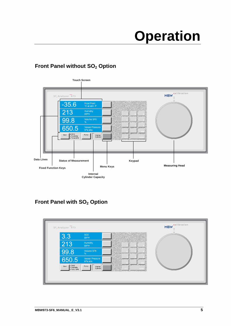
Data Lines The first four lines of the display are for numeric representation of the measured data. We refer to those first four lines as Data Lines. Numeric data lines contain the value to the left, with the parameter description and units to the right. The displayed parameters and units can be changed, but after a restart of the instrument, the values will be reset to the stored standard configuration.
Data Line 1 This line displays the measured Dew/Frost Point. The unit is °C at atmospheric pressure.
In the standard configuration, instruments equipped with the SO2 option show the SO2 concentration expressed in ppmv. The standard SO2 configuration is shown on the second display.
Data Line 2 This line displays the humidity content in either ppmv (parts per million by volume) or ppmw (parts per million by weight). Both units are pressure inde-pendent.
Data Line 3 This line displays the purity in % Volume SF6.
Data Line 4 This line indicates the current pressure of the gas compartment. The unit is kilo Pascal absolute pres-sure.
The data lines indicating the measured humidity and SO2 concentrations as well as the % Volume SF6 will only be displayed after completion of the measurement. Dur-ing the measurement only the current gas pressure of the measured compartment is indicated.
Fixed Function Keys and Status Line
Without SO2 Option
With SO2 Option
The bottom line of the display contains two fixed function keys. The measurement process is started by pressing the Start button. With the Pump button, pump back of stored gas in the internal cylinder can be activated manually. These function keys are not changeable and are always available. Additionally this line contains the status indication, which indi-cates the current operation mode. The level indica-tor of the internal cylinder indicates the current stor-age capacity. A 973 without the SO2 option will dis-play an X next to SO2 to indicate that the meas-urement of SO2 concentration is not available.
MBW973-SF6_MANUAL_E_V3.1 7
Menu Keys
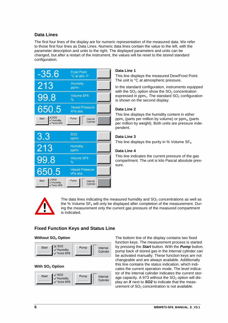
To the right side of the display is a column of menu keys. Each of these keys changes function as needed. Note that the bottom key in this column is different from the rest. The bottom key is used to cycle the upper keys through the various menu options. The text on the bottom key changes to indicate the cur-rently selected menu option. The text of the upper keys change based on the functions available in the menu.
Keypad
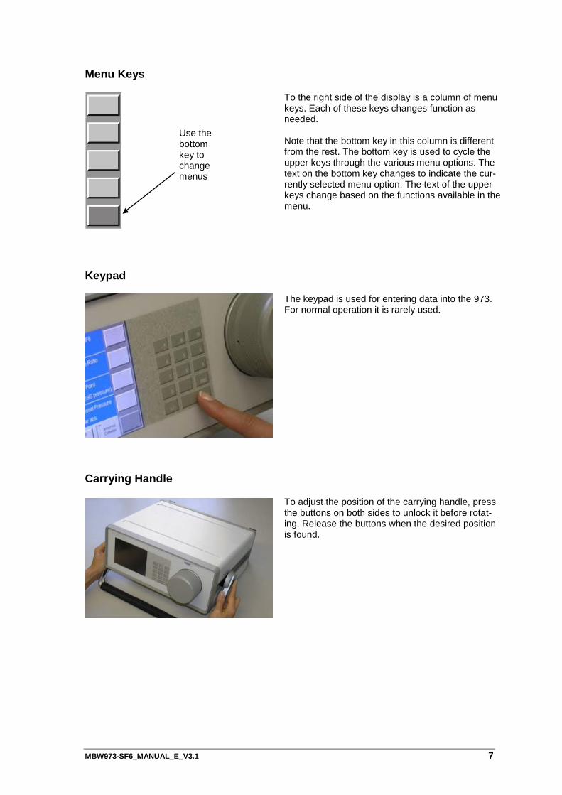
The keypad is used for entering data into the 973. For normal operation it is rarely used.
Carrying Handle
To adjust the position of the carrying handle, press the buttons on both sides to unlock it before rotat-ing. Release the buttons when the desired position is found.
Use the bottom key to change menus
8 MBW973-SF6_MANUAL_E_V3.1
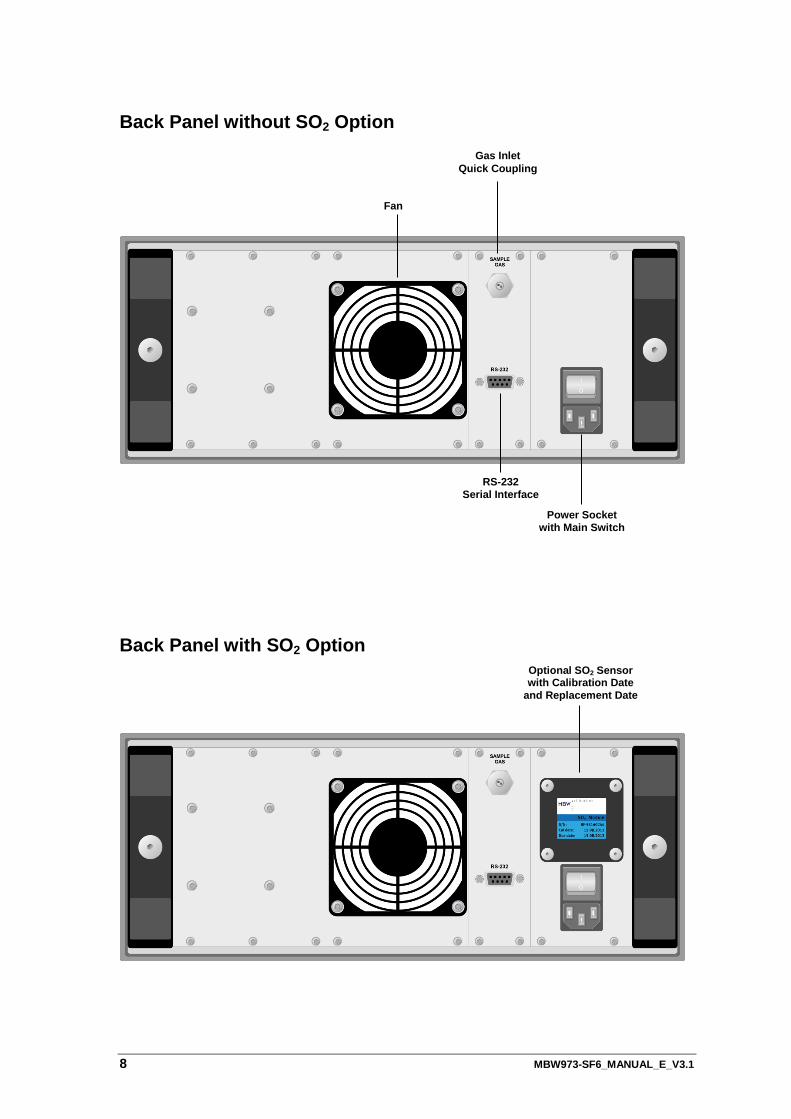
Back Panel without SO2 Option
Back Panel with SO2 Option
Fan
Gas Inlet Quick Coupling
RS-232 Serial Interface
Power Socket with Main Switch
Optional SO2 Sensor with Calibration Date
and Replacement Date
MBW973-SF6_MANUAL_E_V3.1 9
Power Connection The AC power cord is connected to the power socket on the instrument back panel. The power socket also includes the power switch. The power supply voltage is 100-120 VAC / 200-240 VAC at 50 to 60Hz. The power supply is internally fused and will automatically switch off in case of an overload. To restart the power supply, the instrument main switch must be switched to 0 and I again.
SO2-Module When fitted, the SO2 module is mounted to the back panel of the 973 which allows the SO2 sen-sor to be easily replaced by the user. The sensor has to be replaced every two years. The cali-bration and replacement dates are indicated on the SO2 module.
Gas Inlet Quick Coupling The sampling line is connected to the sample gas inlet. If the instrument is not in use the inlet should be protected with the blue cover.
RS-232 Serial Interface Connector The RS-232 connector is used when connecting the 973 to a computer. Use the supplied 9 pin 1:1 cable to connect the 973 to a desktop or laptop computer. This cable has a male connector on one end and a female connector on the other end. It is most often referred to as a serial ex-tension cable.
Fan When the 973 is switched on, the cooling fan always runs independent of the ambient and in-strument temperatures.

10 MBW973-SF6_MANUAL_E_V3.1
MBW973-SF6_MANUAL_E_V3.1 11
Initial Setup
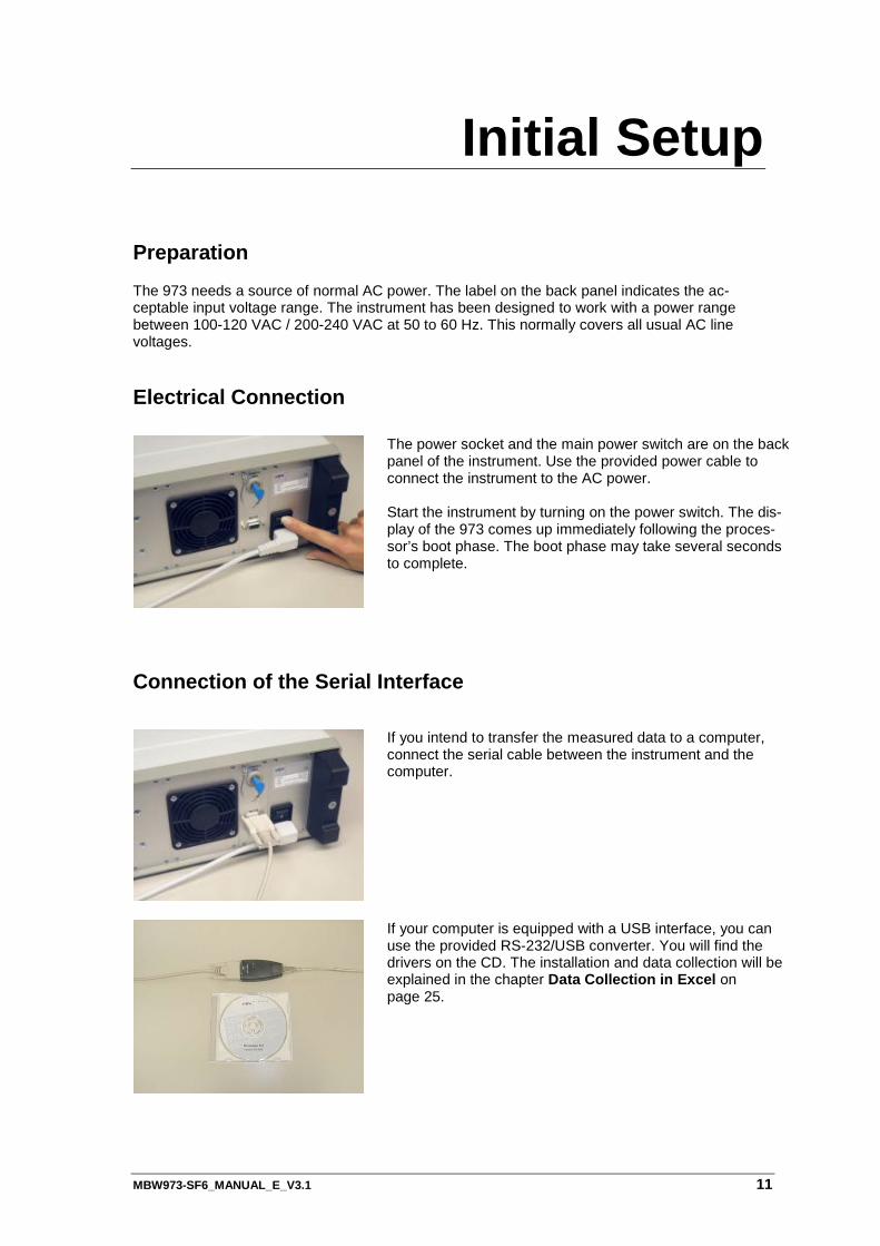
Preparation
The 973 needs a source of normal AC power. The label on the back panel indicates the ac-ceptable input voltage range. The instrument has been designed to work with a power range between 100-120 VAC / 200-240 VAC at 50 to 60 Hz. This normally covers all usual AC line voltages.
Electrical Connection
The power socket and the main power switch are on the back panel of the instrument. Use the provided power cable to connect the instrument to the AC power. Start the instrument by turning on the power switch. The dis-play of the 973 comes up immediately following the proces-sor’s boot phase. The boot phase may take several seconds to complete.
Connection of the Serial Interface
If you intend to transfer the measured data to a computer, connect the serial cable between the instrument and the computer.
If your computer is equipped with a USB interface, you can use the provided RS-232/USB converter. You will find the drivers on the CD. The installation and data collection will be explained in the chapter Data Collection in Excel on page 25.
12 MBW973-SF6_MANUAL_E_V3.1
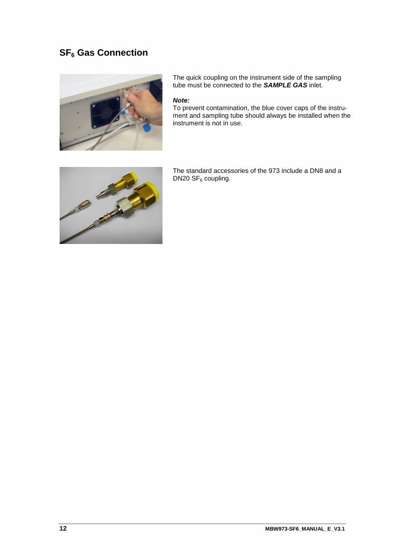
SF6 Gas Connection
The quick coupling on the instrument side of the sampling tube must be connected to the SAMPLE GAS inlet. Note: To prevent contamination, the blue cover caps of the instru-ment and sampling tube should always be installed when the instrument is not in use.
The standard accessories of the 973 include a DN8 and a DN20 SF6 coupling.
MBW973-SF6_MANUAL_E_V3.1 13
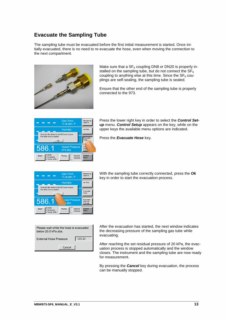
Evacuate the Sampling Tube The sampling tube must be evacuated before the first initial measurement is started. Once ini-tially evacuated, there is no need to re-evacuate the hose, even when moving the connection to the next compartment.
Make sure that a SF6 coupling DN8 or DN20 is properly in-stalled on the sampling tube, but do not connect the SF6 coupling to anything else at this time. Since the SF6 cou-plings are self-sealing, the sampling tube is sealed. Ensure that the other end of the sampling tube is properly connected to the 973.
Press the lower right key in order to select the Control Set-up menu. Control Setup appears on the key, while on the upper keys the available menu options are indicated. Press the Evacuate Hose key.
With the sampling tube correctly connected, press the Ok key in order to start the evacuation process.
After the evacuation has started, the next window indicates the decreasing pressure of the sampling gas tube while evacuating. After reaching the set residual pressure of 20 kPa, the evac-uation process is stopped automatically and the window closes. The instrument and the sampling tube are now ready for measurement. By pressing the Cancel key during evacuation, the process can be manually stopped.
14 MBW973-SF6_MANUAL_E_V3.1
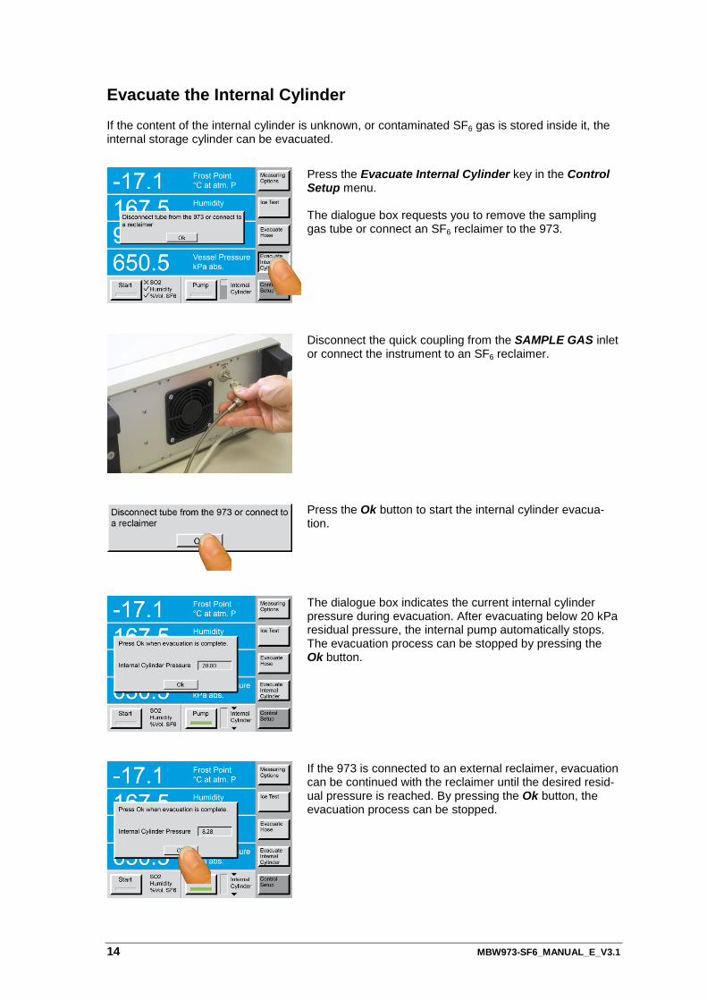
Evacuate the Internal Cylinder If the content of the internal cylinder is unknown, or contaminated SF6 gas is stored inside it, the internal storage cylinder can be evacuated.
Press the Evacuate Internal Cylinder key in the Control Setup menu. The dialogue box requests you to remove the sampling gas tube or connect an SF6 reclaimer to the 973.
Disconnect the quick coupling from the SAMPLE GAS inlet or connect the instrument to an SF6 reclaimer.
Press the Ok button to start the internal cylinder evacua-tion.
The dialogue box indicates the current internal cylinder pressure during evacuation. After evacuating below 20 kPa residual pressure, the internal pump automatically stops. The evacuation process can be stopped by pressing the Ok button.
If the 973 is connected to an external reclaimer, evacuation can be continued with the reclaimer until the desired resid-ual pressure is reached. By pressing the Ok button, the evacuation process can be stopped.
MBW973-SF6_MANUAL_E_V3.1 15
SF6 Gas Connection to the Compartment
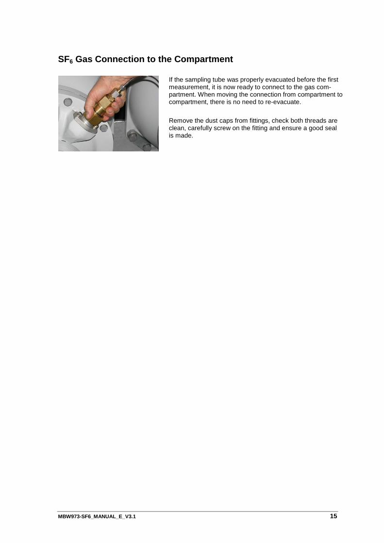
If the sampling tube was properly evacuated before the first measurement, it is now ready to connect to the gas com-partment. When moving the connection from compartment to compartment, there is no need to re-evacuate.
Remove the dust caps from fittings, check both threads are clean, carefully screw on the fitting and ensure a good seal is made.

16 MBW973-SF6_MANUAL_E_V3.1
MBW973-SF6_MANUAL_E_V3.1 17
Measurement Options
Navigating the Menus
The various menus of the right column of keys are navigated by using the key in the lower right corner of the touch screen. Each time you press the lower right key, a new menu appears on the keys directly above it. The menu is circular, meaning that once you go past the last menu, the first one appears again and the process starts over. You can use the ± key on the keypad to move backward through the menus. Use the Enter key to clear the menu.
Selecting the Measurement Options With the measuring options you can select either the humidity measurement, % volume SF6 measurement, or both. In addition, you can select automatic pump back of the stored gas after the termination of the measurement. If the instrument has an SO2 module installed, then the user can also choose to activate or deactivate the SO2 measurement. With the standard 973-SF6 configuration, humidity measurement, % volume SF6 measurement and automatic pump back are selected. This configuration can be changed. However, after restarting the instrument, it will be set back to the standard configuration.
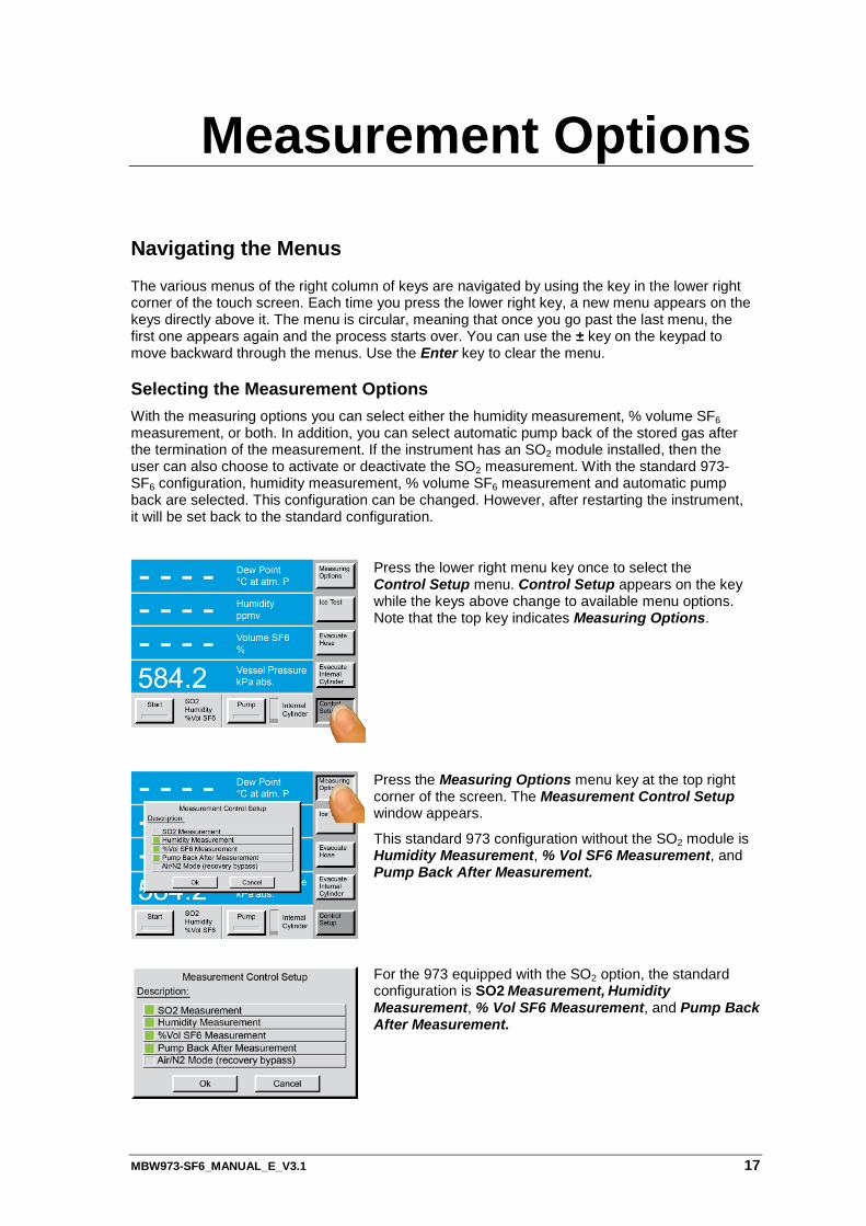
Press the lower right menu key once to select the Control Setup menu. Control Setup appears on the key while the keys above change to available menu options. Note that the top key indicates Measuring Options.
Press the Measuring Options menu key at the top right corner of the screen. The Measurement Control Setup window appears.
This standard 973 configuration without the SO2 module is Humidity Measurement, % Vol SF6 Measurement, and Pump Back After Measurement.
For the 973 equipped with the SO2 option, the standard configuration is SO2 Measurement, Humidity Measurement, % Vol SF6 Measurement, and Pump Back After Measurement.
18 MBW973-SF6_MANUAL_E_V3.1
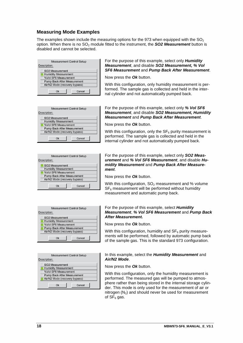
Measuring Mode Examples The examples shown include the measuring options for the 973 when equipped with the SO2 option. When there is no SO2 module fitted to the instrument, the SO2 Measurement button is disabled and cannot be selected.
For the purpose of this example, select only Humidity Measurement, and disable SO2 Measurement, % Vol SF6 Measurement and Pump Back After Measurement.
Now press the Ok button.
With this configuration, only humidity measurement is per-formed. The sample gas is collected and held in the inter-nal cylinder and not automatically pumped back.
For the purpose of this example, select only % Vol SF6 Measurement, and disable SO2 Measurement, Humidity Measurement and Pump Back After Measurement.
Now press the Ok button.
With this configuration, only the SF6 purity measurement is performed. The sample gas is collected and held in the internal cylinder and not automatically pumped back.
For the purpose of this example, select only SO2 Meas-urement and % Vol SF6 Measurement, and disable Hu-midity Measurement and Pump Back After Measure-ment.
Now press the Ok button.
With this configuration, SO2 measurement and % volume SF6 measurement will be performed without humidity measurement and automatic pump back.
For the purpose of this example, select Humidity Measurement, % Vol SF6 Measurement and Pump Back After Measurement.
Now press the Ok button.
With this configuration, humidity and SF6 purity measure-ments will be performed, followed by automatic pump back of the sample gas. This is the standard 973 configuration.
In this example, select the Humidity Measurement and Air/N2 Mode.
Now press the Ok button.
With this configuration, only the humidity measurement is performed. The measured gas will be pumped to atmos-phere rather than being stored in the internal storage cylin-der. This mode is only used for the measurement of air or nitrogen (N2) and should never be used for measurement of SF6 gas.
MBW973-SF6_MANUAL_E_V3.1 19
Measurement
Measurement without SO2 Option
This section describes the measurement sequence for the 973 without the SO2 option. Please refer to page 21 for the equivalent procedure for instruments equipped with the SO2 option. If you intend to collect the measurement data automatically, please install the Excel Protocol sheet, as described on page 25, before the start of the measurement.
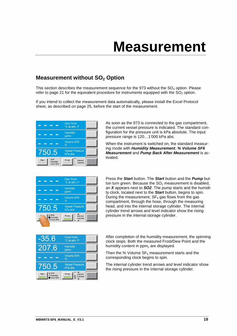
As soon as the 973 is connected to the gas compartment, the current vessel pressure is indicated. The standard con-figuration for the pressure unit is kPa absolute. The input pressure range is 120…1’000 kPa abs.
When the instrument is switched on, the standard measur-ing mode with Humidity Measurement, % Volume SF6 Measurement and Pump Back After Measurement is ac-tivated.
Press the Start button. The Start button and the Pump but-ton turn green. Because the SO2 measurement is disabled, an X appears next to SO2. The pump starts and the humidi-ty clock, located next to the Start button, begins to spin. During the measurement, SF6 gas flows from the gas compartment, through the hose, through the measuring head, and into the internal storage cylinder. The internal cylinder trend arrows and level indicator show the rising pressure in the internal storage cylinder.
After completion of the humidity measurement, the spinning clock stops. Both the measured Frost/Dew Point and the humidity content in ppmv are displayed.
Then the % Volume SF6 measurement starts and the corresponding clock begins to spin.
The internal cylinder trend arrows and level indicator show the rising pressure in the internal storage cylinder.

20 MBW973-SF6_MANUAL_E_V3.1
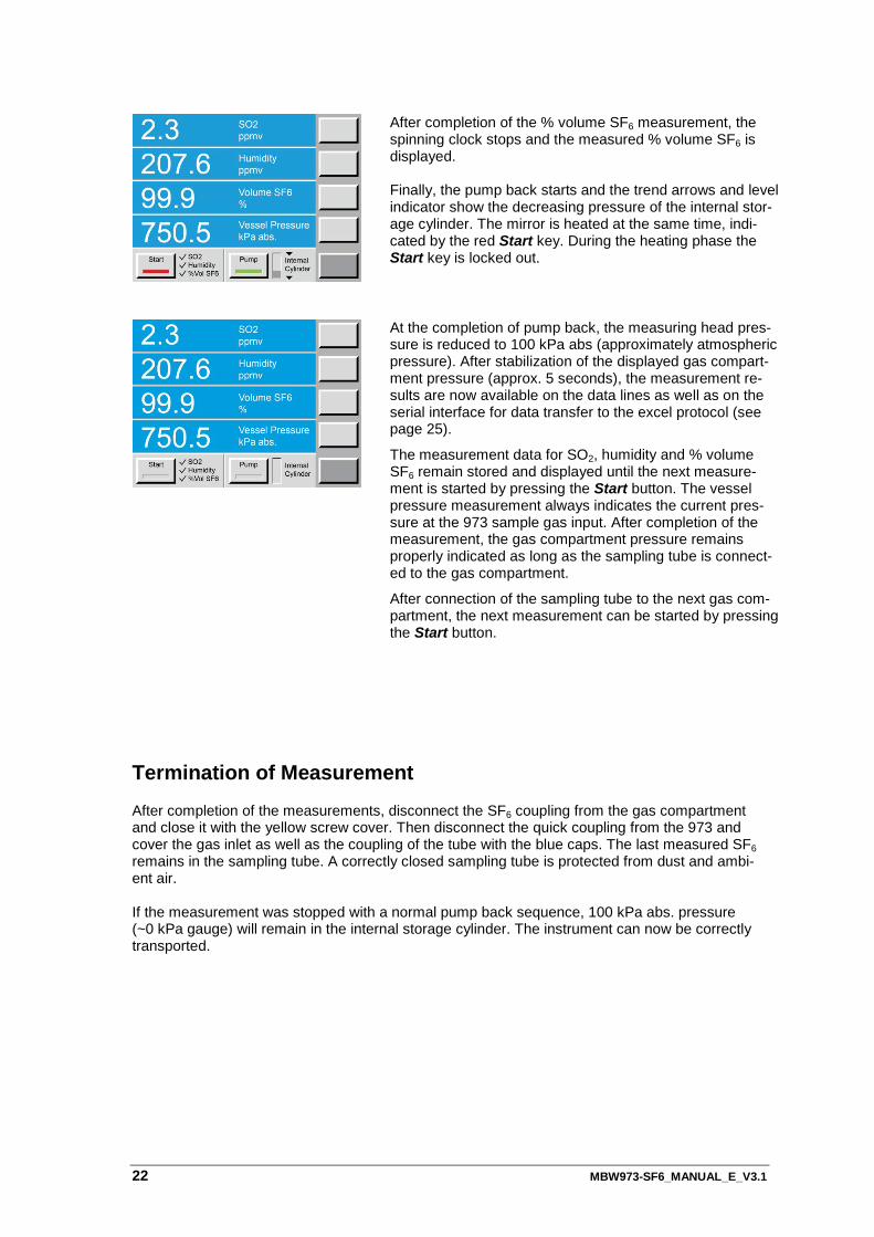
After completion of the % volume SF6 measurement, the spinning clock stops and the measured % volume SF6 is displayed.
Finally, the pump back starts and the trend arrows and level indicator show the decreasing pressure of the internal stor-age cylinder. The mirror is heated at the same time, indi-cated by the red Start key. During the heating phase the Start key is locked out.
At the completion of pump back, the measuring head pres-sure is reduced to 100 kPa abs. (approximately atmospher-ic pressure). After stabilization of the displayed gas com-partment pressure (approx. 5 seconds), the measurement results are now available on the data lines as well as on the serial interface for data transfer to the excel protocol (see page 25).
The measurement data for humidity and % volume SF6 re-main stored and displayed until the next measurement is started by pressing the Start button. The vessel pressure measurement always indicates the current pressure at the 973 sample gas input. After completion of the measure-ment, the gas compartment pressure remains properly indi-cated as long as the sampling tube is connected to the gas compartment.
After connection of the sampling tube to the next gas com-partment, the next measurement can be started by pressing the Start button.
Termination of Measurement After completion of the measurements, disconnect the SF6 coupling from the gas compartment and close it with the yellow screw cover. Then disconnect the quick coupling from the 973 and cover the gas inlet as well as the coupling of the tube with the blue caps. The last measured SF6 remains in the sampling tube. A correctly closed sampling tube is protected from dust and ambi-ent air. If the measurement was stopped with a normal pump back sequence, 100 kPa abs. pressure (~0 kPa gauge) will remain in the internal storage cylinder. The instrument can now be correctly transported.
MBW973-SF6_MANUAL_E_V3.1 21
Measurement with SO2 Option The section describes the measurement procedure for the 973 equipped with the SO2 option. Refer to page 19 for equivalent procedures for instruments without the SO2 option. If you intend to collect the measurement data automatically, please install the Excel Protocol sheet, as described on page 25, before the start of the measurement.
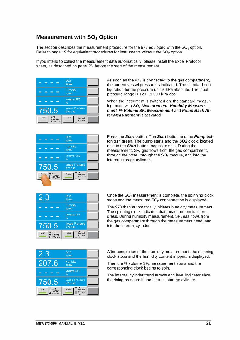
As soon as the 973 is connected to the gas compartment, the current vessel pressure is indicated. The standard con-figuration for the pressure unit is kPa absolute. The input pressure range is 120…1’000 kPa abs.
When the instrument is switched on, the standard measur-ing mode with SO2 Measurement, Humidity Measure-ment, % Volume SF6 Measurement and Pump Back Af-ter Measurement is activated.
Press the Start button. The Start button and the Pump but-ton turn green. The pump starts and the SO2 clock, located next to the Start button, begins to spin. During the measurement, SF6 gas flows from the gas compartment, through the hose, through the SO2 module, and into the internal storage cylinder.
Once the SO2 measurement is complete, the spinning clock stops and the measured SO2 concentration is displayed.
The 973 then automatically initiates humidity measurement. The spinning clock indicates that measurement is in pro-gress. During humidity measurement, SF6 gas flows from the gas compartment through the measurement head, and into the internal cylinder.
After completion of the humidity measurement, the spinning clock stops and the humidity content in ppmv is displayed.
Then the % volume SF6 measurement starts and the corresponding clock begins to spin.
The internal cylinder trend arrows and level indicator show the rising pressure in the internal storage cylinder.
22 MBW973-SF6_MANUAL_E_V3.1
After completion of the % volume SF6 measurement, the spinning clock stops and the measured % volume SF6 is displayed. Finally, the pump back starts and the trend arrows and level indicator show the decreasing pressure of the internal stor-age cylinder. The mirror is heated at the same time, indi-cated by the red Start key. During the heating phase the Start key is locked out.
At the completion of pump back, the measuring head pres-sure is reduced to 100 kPa abs (approximately atmospheric pressure). After stabilization of the displayed gas compart-ment pressure (approx. 5 seconds), the measurement re-sults are now available on the data lines as well as on the serial interface for data transfer to the excel protocol (see page 25).
The measurement data for SO2, humidity and % volume SF6 remain stored and displayed until the next measure-ment is started by pressing the Start button. The vessel pressure measurement always indicates the current pres-sure at the 973 sample gas input. After completion of the measurement, the gas compartment pressure remains properly indicated as long as the sampling tube is connect-ed to the gas compartment.
After connection of the sampling tube to the next gas com-partment, the next measurement can be started by pressing the Start button.
Termination of Measurement
After completion of the measurements, disconnect the SF6 coupling from the gas compartment and close it with the yellow screw cover. Then disconnect the quick coupling from the 973 and cover the gas inlet as well as the coupling of the tube with the blue caps. The last measured SF6 remains in the sampling tube. A correctly closed sampling tube is protected from dust and ambi-ent air. If the measurement was stopped with a normal pump back sequence, 100 kPa abs. pressure (~0 kPa gauge) will remain in the internal storage cylinder. The instrument can now be correctly transported.
MBW973-SF6_MANUAL_E_V3.1 23
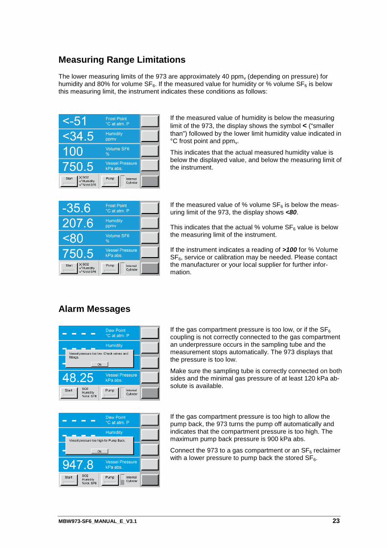
Measuring Range Limitations The lower measuring limits of the 973 are approximately 40 ppmv (depending on pressure) for humidity and 80% for volume SF6. If the measured value for humidity or % volume SF6 is below this measuring limit, the instrument indicates these conditions as follows:
If the measured value of humidity is below the measuring limit of the 973, the display shows the symbol < (“smaller than”) followed by the lower limit humidity value indicated in °C frost point and ppmv.
This indicates that the actual measured humidity value is below the displayed value, and below the measuring limit of the instrument.
If the measured value of % volume SF6 is below the meas-uring limit of the 973, the display shows <80.
This indicates that the actual % volume SF6 value is below the measuring limit of the instrument. If the instrument indicates a reading of >100 for % Volume SF6, service or calibration may be needed. Please contact the manufacturer or your local supplier for further infor-mation.
Alarm Messages
If the gas compartment pressure is too low, or if the SF6 coupling is not correctly connected to the gas compartment an underpressure occurs in the sampling tube and the measurement stops automatically. The 973 displays that the pressure is too low.
Make sure the sampling tube is correctly connected on both sides and the minimal gas pressure of at least 120 kPa ab-solute is available.
If the gas compartment pressure is too high to allow the pump back, the 973 turns the pump off automatically and indicates that the compartment pressure is too high. The maximum pump back pressure is 900 kPa abs.
Connect the 973 to a gas compartment or an SF6 reclaimer with a lower pressure to pump back the stored SF6.
24 MBW973-SF6_MANUAL_E_V3.1
Measurement Aborted If the measurement is aborted due to low or high pressure conditions, the 973 will heat up the mirror, restore the measuring head pressure to 100 kPa abs (approximately atmospheric pres-sure), and stop. Pump back of the stored gas in the internal cylinder can be started by pressing the Pump key.
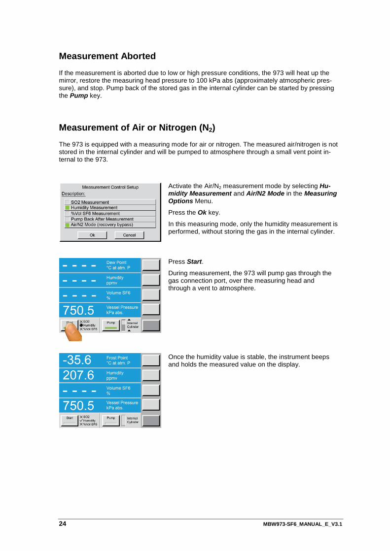
Measurement of Air or Nitrogen (N2) The 973 is equipped with a measuring mode for air or nitrogen. The measured air/nitrogen is not stored in the internal cylinder and will be pumped to atmosphere through a small vent point in-ternal to the 973.
Activate the Air/N2 measurement mode by selecting Hu-midity Measurement and Air/N2 Mode in the Measuring Options Menu.
Press the Ok key.
In this measuring mode, only the humidity measurement is performed, without storing the gas in the internal cylinder.
Press Start.
During measurement, the 973 will pump gas through the gas connection port, over the measuring head and through a vent to atmosphere.
Once the humidity value is stable, the instrument beeps and holds the measured value on the display.
MBW973-SF6_MANUAL_E_V3.1 25
Data Collection in Excel
RS-232 – USB Converter Installation
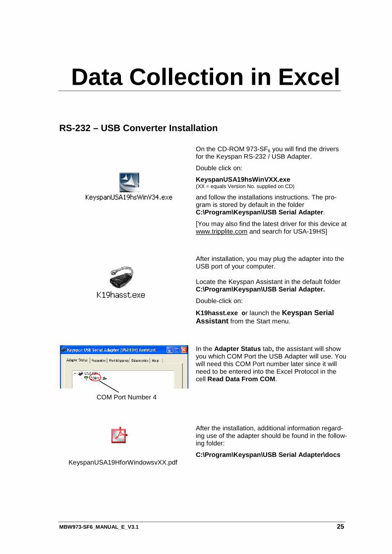
On the CD-ROM 973-SF6 you will find the drivers for the Keyspan RS-232 / USB Adapter.
Double click on:
KeyspanUSA19hsWinVXX.exe (XX = equals Version No. supplied on CD) and follow the installations instructions. The pro-gram is stored by default in the folder C:\Program\Keyspan\USB Serial Adapter.
[You may also find the latest driver for this device at www.tripplite.com and search for USA-19HS]
After installation, you may plug the adapter into the USB port of your computer.
Locate the Keyspan Assistant in the default folder C:\Program\Keyspan\USB Serial Adapter.
Double-click on:
K19hasst.exe or launch the Keyspan Serial Assistant from the Start menu.
COM Port Number 4
In the Adapter Status tab, the assistant will show you which COM Port the USB Adapter will use. You will need this COM Port number later since it will need to be entered into the Excel Protocol in the cell Read Data From COM.
KeyspanUSA19HforWindowsvXX.pdf
After the installation, additional information regard-ing use of the adapter should be found in the follow-ing folder:
C:\Program\Keyspan\USB Serial Adapter\docs
26 MBW973-SF6_MANUAL_E_V3.1
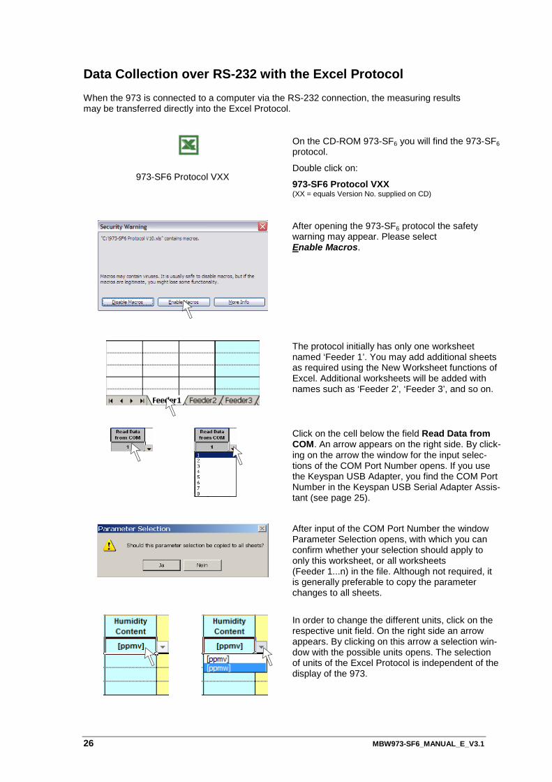
Data Collection over RS-232 with the Excel Protocol When the 973 is connected to a computer via the RS-232 connection, the measuring results may be transferred directly into the Excel Protocol.
973-SF6 Protocol VXX
On the CD-ROM 973-SF6 you will find the 973-SF6 protocol.
Double click on:
973-SF6 Protocol VXX (XX = equals Version No. supplied on CD)
After opening the 973-SF6 protocol the safety warning may appear. Please select Enable Macros.
The protocol initially has only one worksheet named ‘Feeder 1’. You may add additional sheets as required using the New Worksheet functions of Excel. Additional worksheets will be added with names such as ‘Feeder 2’, ‘Feeder 3’, and so on.
Click on the cell below the field Read Data from COM. An arrow appears on the right side. By click-ing on the arrow the window for the input selec-tions of the COM Port Number opens. If you use the Keyspan USB Adapter, you find the COM Port Number in the Keyspan USB Serial Adapter Assis-tant (see page 25).
After input of the COM Port Number the window Parameter Selection opens, with which you can confirm whether your selection should apply to only this worksheet, or all worksheets (Feeder 1...n) in the file. Although not required, it is generally preferable to copy the parameter changes to all sheets.
In order to change the different units, click on the respective unit field. On the right side an arrow appears. By clicking on this arrow a selection win-dow with the possible units opens. The selection of units of the Excel Protocol is independent of the display of the 973.
MBW973-SF6_MANUAL_E_V3.1 27
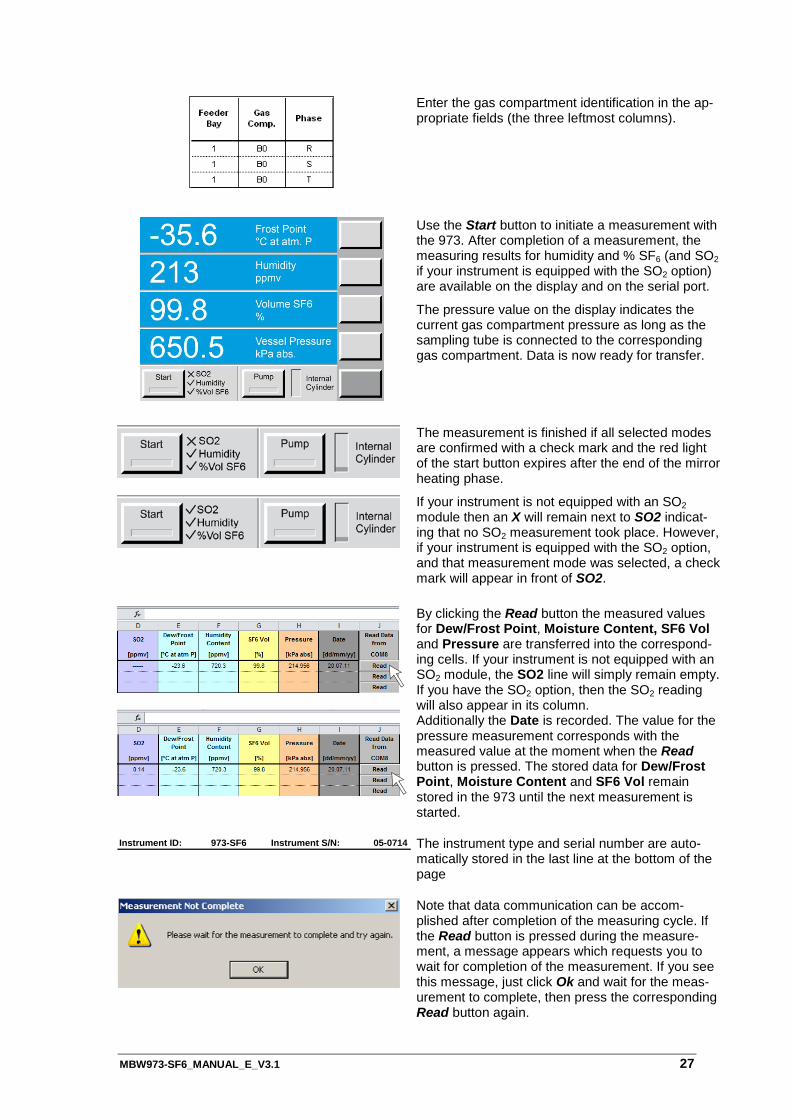
Enter the gas compartment identification in the ap-propriate fields (the three leftmost columns).
Use the Start button to initiate a measurement with the 973. After completion of a measurement, the measuring results for humidity and % SF6 (and SO2 if your instrument is equipped with the SO2 option) are available on the display and on the serial port.
The pressure value on the display indicates the current gas compartment pressure as long as the sampling tube is connected to the corresponding gas compartment. Data is now ready for transfer.
The measurement is finished if all selected modes are confirmed with a check mark and the red light of the start button expires after the end of the mirror heating phase.
If your instrument is not equipped with an SO2 module then an X will remain next to SO2 indicat-ing that no SO2 measurement took place. However, if your instrument is equipped with the SO2 option, and that measurement mode was selected, a check mark will appear in front of SO2.
By clicking the Read button the measured values for Dew/Frost Point, Moisture Content, SF6 Vol and Pressure are transferred into the correspond-ing cells. If your instrument is not equipped with an SO2 module, the SO2 line will simply remain empty. If you have the SO2 option, then the SO2 reading will also appear in its column. Additionally the Date is recorded. The value for the pressure measurement corresponds with the measured value at the moment when the Read button is pressed. The stored data for Dew/Frost Point, Moisture Content and SF6 Vol remain stored in the 973 until the next measurement is started.
The instrument type and serial number are auto-matically stored in the last line at the bottom of the page
Note that data communication can be accom-plished after completion of the measuring cycle. If the Read button is pressed during the measure-ment, a message appears which requests you to wait for completion of the measurement. If you see this message, just click Ok and wait for the meas-urement to complete, then press the corresponding Read button again.
Instrument ID: 973-SF6 Instrument S/N: 05-0714

28 MBW973-SF6_MANUAL_E_V3.1
MBW973-SF6_MANUAL_E_V3.1 29
SO2 Module
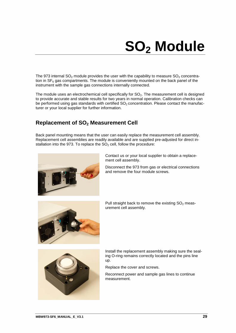
The 973 internal SO2 module provides the user with the capability to measure SO2 concentra-tion in SF6 gas compartments. The module is conveniently mounted on the back panel of the instrument with the sample gas connections internally connected. The module uses an electrochemical cell specifically for SO2. The measurement cell is designed to provide accurate and stable results for two years in normal operation. Calibration checks can be performed using gas standards with certified SO2 concentration. Please contact the manufac-turer or your local supplier for further information.
Replacement of SO2 Measurement Cell Back panel mounting means that the user can easily replace the measurement cell assembly. Replacement cell assemblies are readily available and are supplied pre-adjusted for direct in-stallation into the 973. To replace the SO2 cell, follow the procedure:
Contact us or your local supplier to obtain a replace-ment cell assembly.
Disconnect the 973 from gas or electrical connections and remove the four module screws.
Pull straight back to remove the existing SO2 meas-urement cell assembly.
Install the replacement assembly making sure the seal-ing O-ring remains correctly located and the pins line up.
Replace the cover and screws.
Reconnect power and sample gas lines to continue measurement.
30 MBW973-SF6_MANUAL_E_V3.1
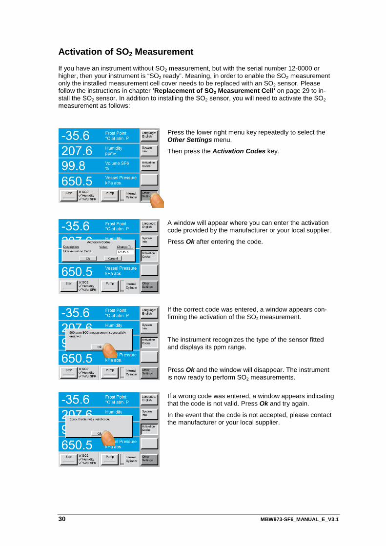
Activation of SO2 Measurement If you have an instrument without SO2 measurement, but with the serial number 12-0000 or higher, then your instrument is “SO2 ready”. Meaning, in order to enable the SO2 measurement only the installed measurement cell cover needs to be replaced with an SO2 sensor. Please follow the instructions in chapter ‘Replacement of SO2 Measurement Cell’ on page 29 to in-stall the SO2 sensor. In addition to installing the SO2 sensor, you will need to activate the SO2 measurement as follows:
Press the lower right menu key repeatedly to select the Other Settings menu.
Then press the Activation Codes key.
A window will appear where you can enter the activation code provided by the manufacturer or your local supplier.
Press Ok after entering the code.
If the correct code was entered, a window appears con-firming the activation of the SO2 measurement.
The instrument recognizes the type of the sensor fitted and displays its ppm range.
Press Ok and the window will disappear. The instrument is now ready to perform SO2 measurements.
If a wrong code was entered, a window appears indicating that the code is not valid. Press Ok and try again.
In the event that the code is not accepted, please contact the manufacturer or your local supplier.

MBW973-SF6_MANUAL_E_V3.1 31
32 MBW973-SF6_MANUAL_E_V3.1
Test Functions
Ice Test
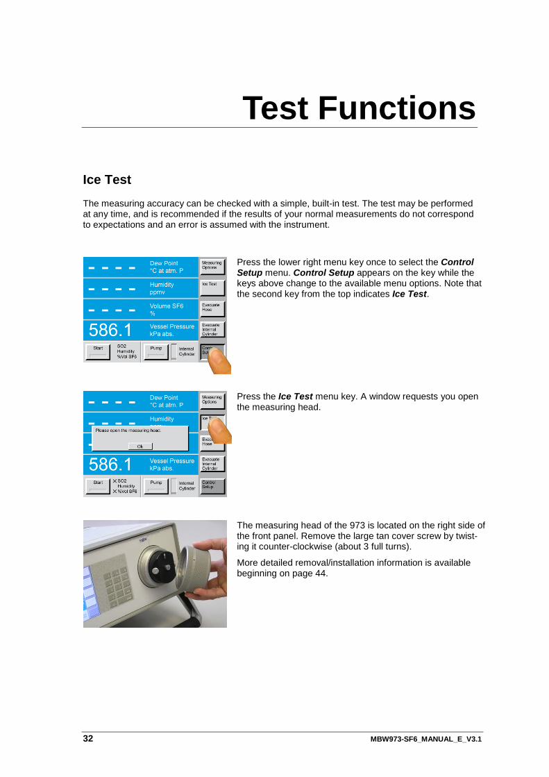
The measuring accuracy can be checked with a simple, built-in test. The test may be performed at any time, and is recommended if the results of your normal measurements do not correspond to expectations and an error is assumed with the instrument.
Press the lower right menu key once to select the Control Setup menu. Control Setup appears on the key while the keys above change to the available menu options. Note that the second key from the top indicates Ice Test.
Press the Ice Test menu key. A window requests you open the measuring head.
The measuring head of the 973 is located on the right side of the front panel. Remove the large tan cover screw by twist-ing it counter-clockwise (about 3 full turns).
More detailed removal/installation information is available beginning on page 44.
MBW973-SF6_MANUAL_E_V3.1 33
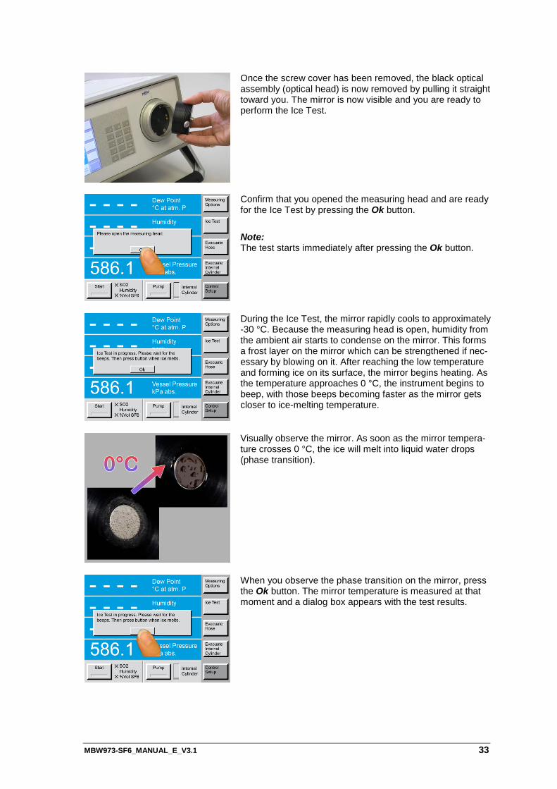
Once the screw cover has been removed, the black optical assembly (optical head) is now removed by pulling it straight toward you. The mirror is now visible and you are ready to perform the Ice Test.
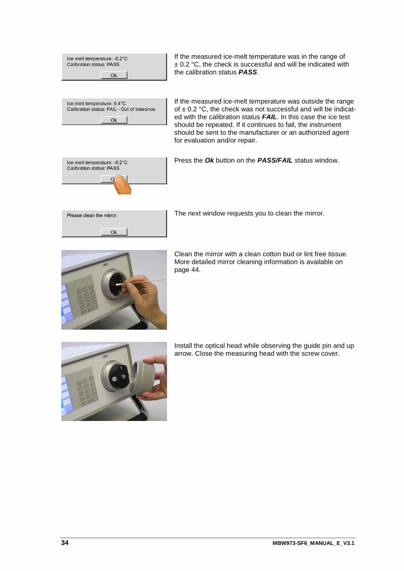
Confirm that you opened the measuring head and are ready for the Ice Test by pressing the Ok button.
Note: The test starts immediately after pressing the Ok button.
During the Ice Test, the mirror rapidly cools to approximately -30 °C. Because the measuring head is open, humidity from the ambient air starts to condense on the mirror. This forms a frost layer on the mirror which can be strengthened if nec-essary by blowing on it. After reaching the low temperature and forming ice on its surface, the mirror begins heating. As the temperature approaches 0 °C, the instrument begins to beep, with those beeps becoming faster as the mirror gets closer to ice-melting temperature.
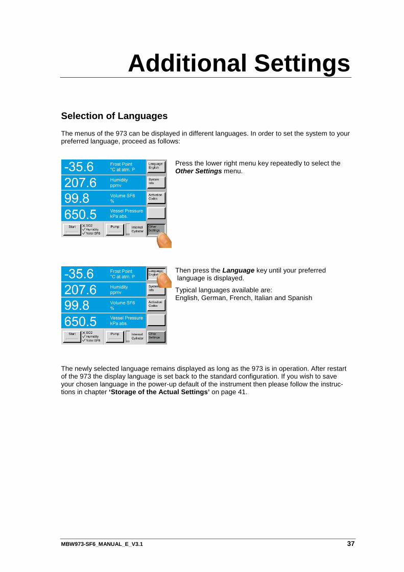
Visually observe the mirror. As soon as the mirror tempera-ture crosses 0 °C, the ice will melt into liquid water drops (phase transition).
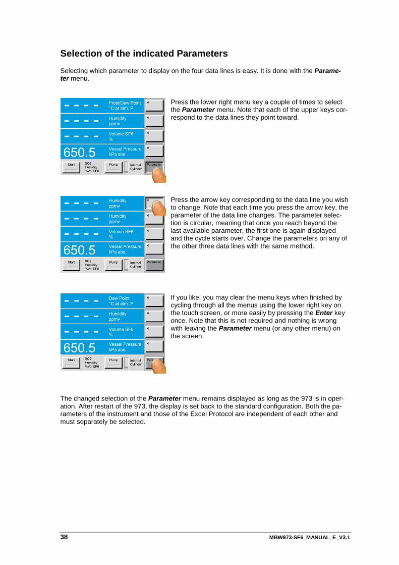
When you observe the phase transition on the mirror, press the Ok button. The mirror temperature is measured at that moment and a dialog box appears with the test results.
34 MBW973-SF6_MANUAL_E_V3.1
If the measured ice-melt temperature was in the range of ± 0.2 °C, the check is successful and will be indicated with the calibration status PASS.
If the measured ice-melt temperature was outside the range of ± 0.2 °C, the check was not successful and will be indicat-ed with the calibration status FAIL. In this case the ice test should be repeated. If it continues to fail, the instrument should be sent to the manufacturer or an authorized agent for evaluation and/or repair.
Press the Ok button on the PASS/FAIL status window.
The next window requests you to clean the mirror.
Clean the mirror with a clean cotton bud or lint free tissue. More detailed mirror cleaning information is available on page 44.
Install the optical head while observing the guide pin and up arrow. Close the measuring head with the screw cover.

MBW973-SF6_MANUAL_E_V3.1 35

MBW973-SF6_MANUAL_E_V3.1 37
Additional Settings
Selection of Languages
The menus of the 973 can be displayed in different languages. In order to set the system to your preferred language, proceed as follows:
The newly selected language remains displayed as long as the 973 is in operation. After restart of the 973 the display language is set back to the standard configuration. If you wish to save your chosen language in the power-up default of the instrument then please follow the instruc-tions in chapter ‘Storage of the Actual Settings’ on page 41.
Press the lower right menu key repeatedly to select the Other Settings menu.
Then press the Language key until your preferred language is displayed.
Typical languages available are: English, German, French, Italian and Spanish
38 MBW973-SF6_MANUAL_E_V3.1
Selection of the indicated Parameters Selecting which parameter to display on the four data lines is easy. It is done with the Parame-ter menu.
Press the lower right menu key a couple of times to select the Parameter menu. Note that each of the upper keys cor-respond to the data lines they point toward.
Press the arrow key corresponding to the data line you wish to change. Note that each time you press the arrow key, the parameter of the data line changes. The parameter selec-tion is circular, meaning that once you reach beyond the last available parameter, the first one is again displayed and the cycle starts over. Change the parameters on any of the other three data lines with the same method.
If you like, you may clear the menu keys when finished by cycling through all the menus using the lower right key on the touch screen, or more easily by pressing the Enter key once. Note that this is not required and nothing is wrong with leaving the Parameter menu (or any other menu) on the screen.
The changed selection of the Parameter menu remains displayed as long as the 973 is in oper-ation. After restart of the 973, the display is set back to the standard configuration. Both the pa-rameters of the instrument and those of the Excel Protocol are independent of each other and must separately be selected.
MBW973-SF6_MANUAL_E_V3.1 39
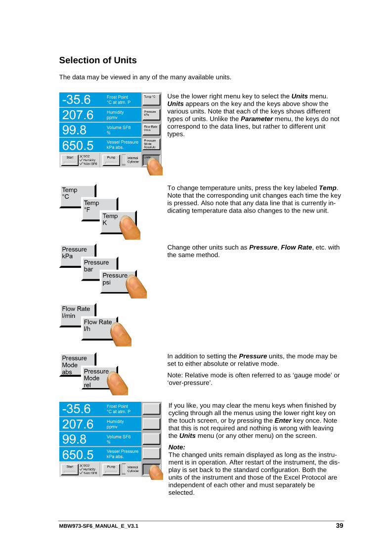
Selection of Units The data may be viewed in any of the many available units.
Use the lower right menu key to select the Units menu. Units appears on the key and the keys above show the various units. Note that each of the keys shows different types of units. Unlike the Parameter menu, the keys do not correspond to the data lines, but rather to different unit types.
To change temperature units, press the key labeled Temp. Note that the corresponding unit changes each time the key is pressed. Also note that any data line that is currently in-dicating temperature data also changes to the new unit.
Change other units such as Pressure, Flow Rate, etc. with the same method.
In addition to setting the Pressure units, the mode may be set to either absolute or relative mode.
Note: Relative mode is often referred to as ‘gauge mode’ or ‘over-pressure’.
If you like, you may clear the menu keys when finished by cycling through all the menus using the lower right key on the touch screen, or by pressing the Enter key once. Note that this is not required and nothing is wrong with leaving the Units menu (or any other menu) on the screen.
Note: The changed units remain displayed as long as the instru-ment is in operation. After restart of the instrument, the dis-play is set back to the standard configuration. Both the units of the instrument and those of the Excel Protocol are independent of each other and must separately be selected.
40 MBW973-SF6_MANUAL_E_V3.1
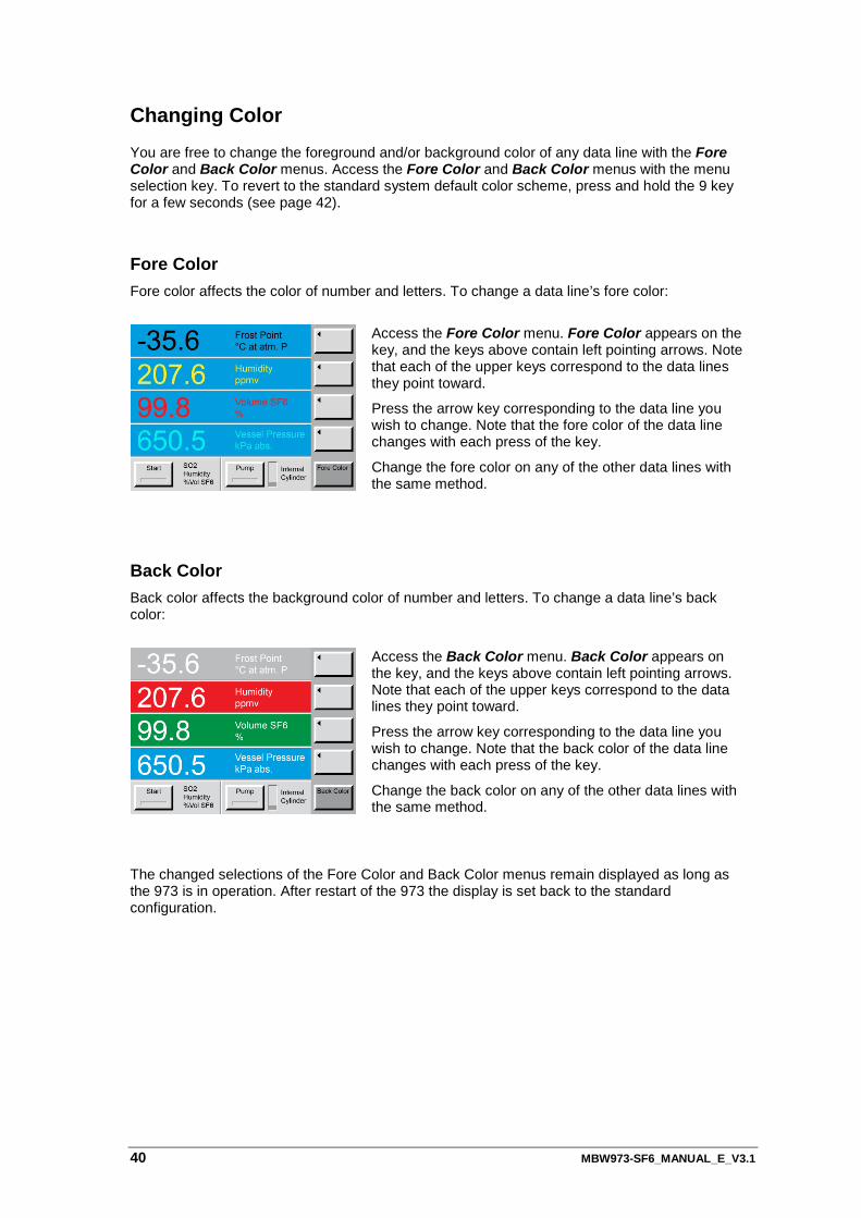
Changing Color You are free to change the foreground and/or background color of any data line with the Fore Color and Back Color menus. Access the Fore Color and Back Color menus with the menu selection key. To revert to the standard system default color scheme, press and hold the 9 key for a few seconds (see page 42).
Fore Color Fore color affects the color of number and letters. To change a data line’s fore color:
Access the Fore Color menu. Fore Color appears on the key, and the keys above contain left pointing arrows. Note that each of the upper keys correspond to the data lines they point toward.
Press the arrow key corresponding to the data line you wish to change. Note that the fore color of the data line changes with each press of the key.
Change the fore color on any of the other data lines with the same method.
Back Color Back color affects the background color of number and letters. To change a data line’s back color:
Access the Back Color menu. Back Color appears on the key, and the keys above contain left pointing arrows. Note that each of the upper keys correspond to the data lines they point toward.
Press the arrow key corresponding to the data line you wish to change. Note that the back color of the data line changes with each press of the key.
Change the back color on any of the other data lines with the same method.
The changed selections of the Fore Color and Back Color menus remain displayed as long as the 973 is in operation. After restart of the 973 the display is set back to the standard configuration.
MBW973-SF6_MANUAL_E_V3.1 41
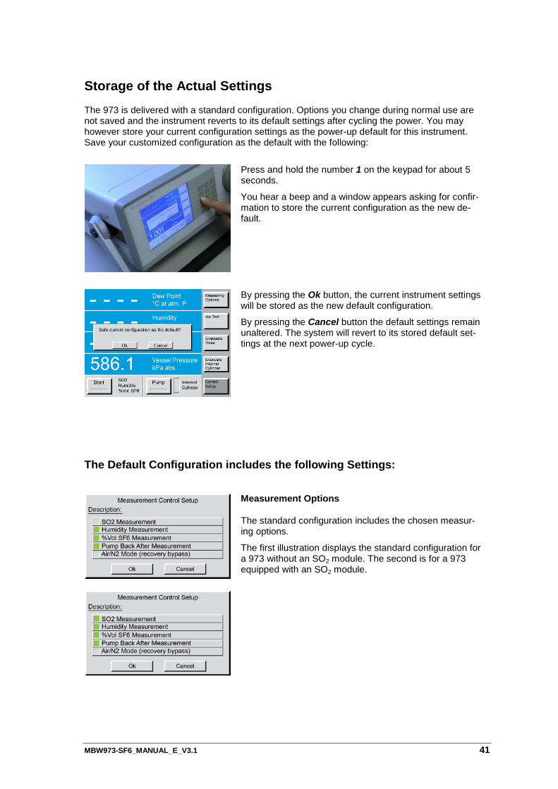
Storage of the Actual Settings The 973 is delivered with a standard configuration. Options you change during normal use are not saved and the instrument reverts to its default settings after cycling the power. You may however store your current configuration settings as the power-up default for this instrument. Save your customized configuration as the default with the following:
Press and hold the number 1 on the keypad for about 5 seconds.
You hear a beep and a window appears asking for confir-mation to store the current configuration as the new de-fault.
By pressing the Ok button, the current instrument settings will be stored as the new default configuration.
By pressing the Cancel button the default settings remain unaltered. The system will revert to its stored default set-tings at the next power-up cycle.
The Default Configuration includes the following Settings:
Measurement Options
The standard configuration includes the chosen measur-ing options.
The first illustration displays the standard configuration for a 973 without an SO2 module. The second is for a 973 equipped with an SO2 module.
42 MBW973-SF6_MANUAL_E_V3.1
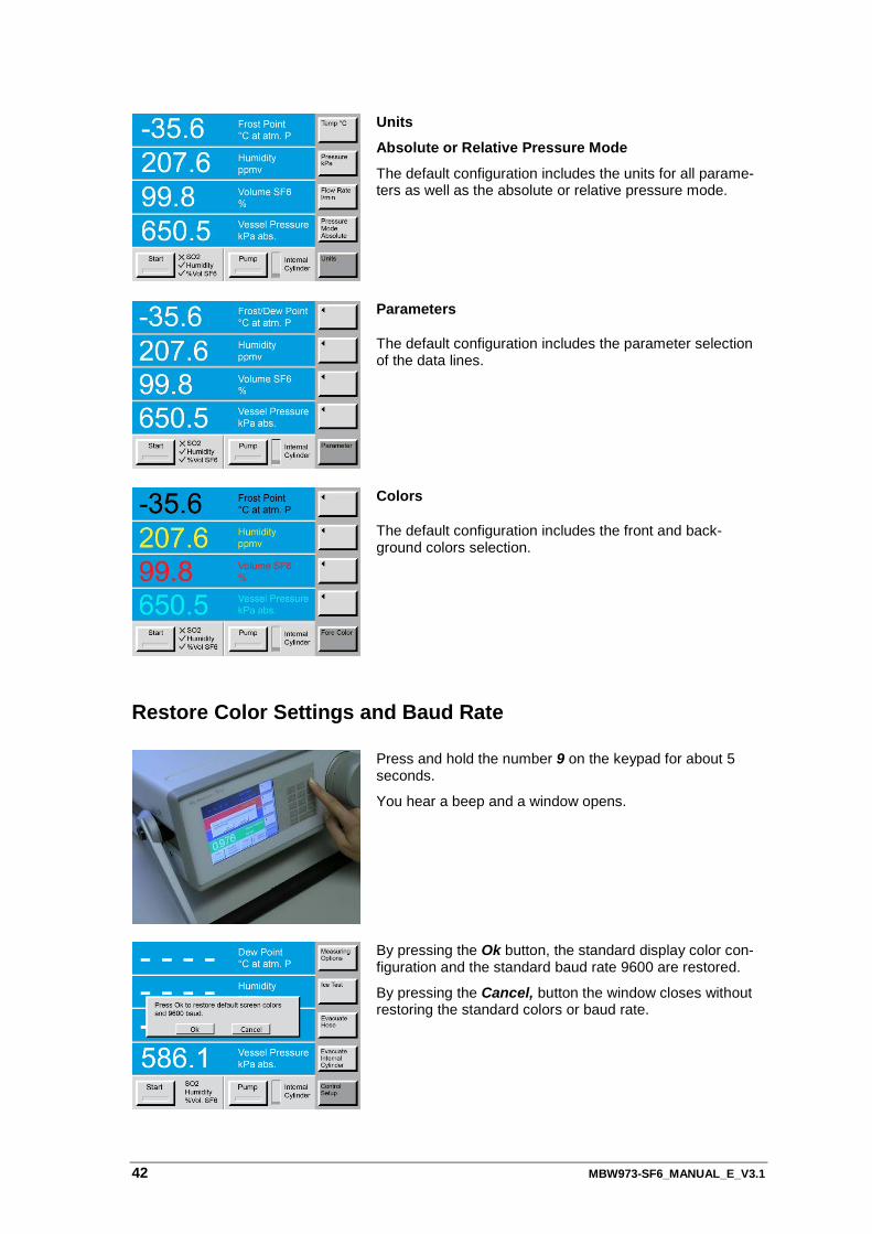
Units
Absolute or Relative Pressure Mode
The default configuration includes the units for all parame-ters as well as the absolute or relative pressure mode.
Parameters
The default configuration includes the parameter selection of the data lines.
Colors
The default configuration includes the front and back-ground colors selection.
Restore Color Settings and Baud Rate
Press and hold the number 9 on the keypad for about 5 seconds.
You hear a beep and a window opens.
By pressing the Ok button, the standard display color con-figuration and the standard baud rate 9600 are restored.
By pressing the Cancel, button the window closes without restoring the standard colors or baud rate.
MBW973-SF6_MANUAL_E_V3.1 43
Maintenance
Touch Screen Calibration
The 973 utilizes a touch screen for user interaction. To activate a menu option or toggle a func-tion on or off, simply touch the screen directly over the key or object desired. Before using the instrument for the first time, or when the instrument is used by different opera-tors, you may need to calibrate the touch screen to your finger positioning preference. Left and right handed people, for example, may have different points of pressure when using the touch screen. To calibrate the touch screen, follow the instructions:
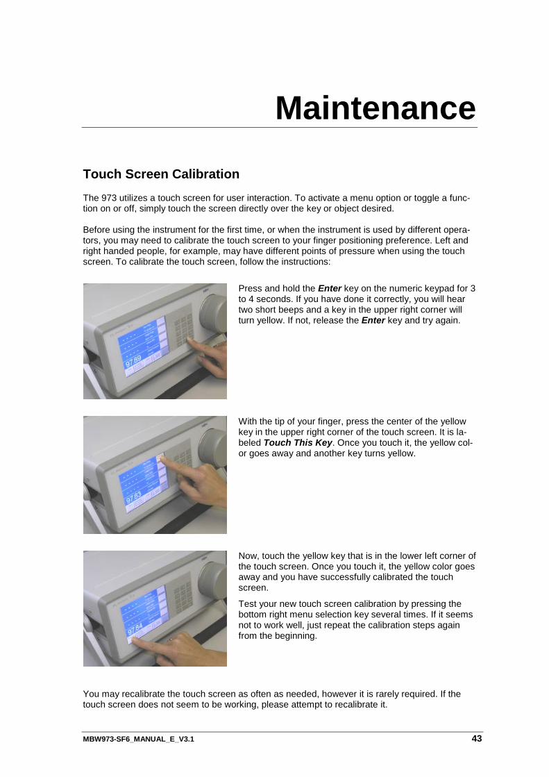
Press and hold the Enter key on the numeric keypad for 3 to 4 seconds. If you have done it correctly, you will hear two short beeps and a key in the upper right corner will turn yellow. If not, release the Enter key and try again.
With the tip of your finger, press the center of the yellow key in the upper right corner of the touch screen. It is la-beled Touch This Key. Once you touch it, the yellow col-or goes away and another key turns yellow.
Now, touch the yellow key that is in the lower left corner of the touch screen. Once you touch it, the yellow color goes away and you have successfully calibrated the touch screen.
Test your new touch screen calibration by pressing the bottom right menu selection key several times. If it seems not to work well, just repeat the calibration steps again from the beginning.
You may recalibrate the touch screen as often as needed, however it is rarely required. If the touch screen does not seem to be working, please attempt to recalibrate it.
44 MBW973-SF6_MANUAL_E_V3.1
Mirror Cleaning The heart of the 973 is the measuring head assembly. It is designed to be highly sensitive and accurate, yet rugged and easily accessible for periodic mirror cleaning. To ensure high accura-cy, the mirror should be cleaned before starting a series of measurements. After removing the screw cover and the measuring head optical assembly, the mirror is easily accessible.
Request for Mirror Cleaning
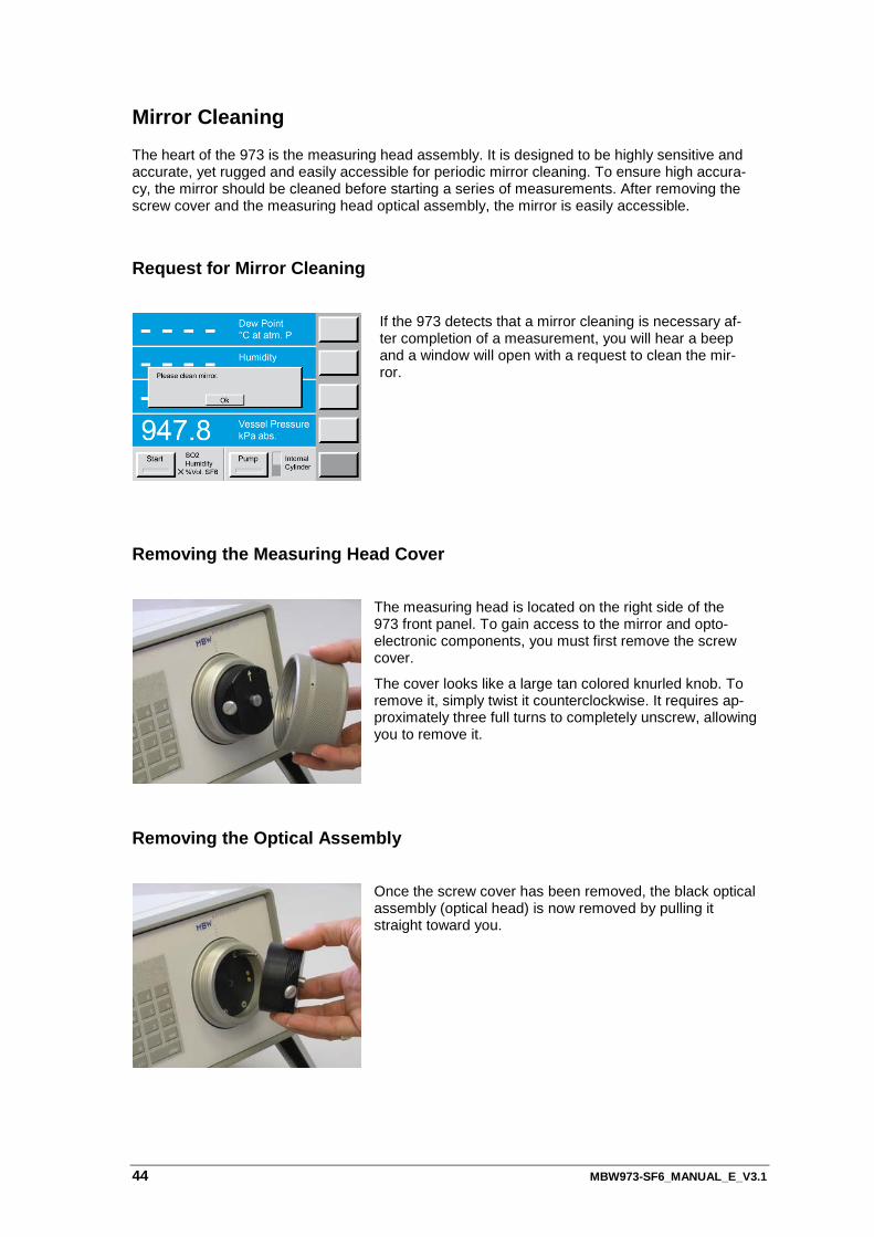
If the 973 detects that a mirror cleaning is necessary af-ter completion of a measurement, you will hear a beep and a window will open with a request to clean the mir-ror.
Removing the Measuring Head Cover
The measuring head is located on the right side of the 973 front panel. To gain access to the mirror and opto-electronic components, you must first remove the screw cover.
The cover looks like a large tan colored knurled knob. To remove it, simply twist it counterclockwise. It requires ap-proximately three full turns to completely unscrew, allowing you to remove it.
Removing the Optical Assembly
Once the screw cover has been removed, the black optical assembly (optical head) is now removed by pulling it straight toward you.
MBW973-SF6_MANUAL_E_V3.1 45
Inspecting / Cleaning the Mirror
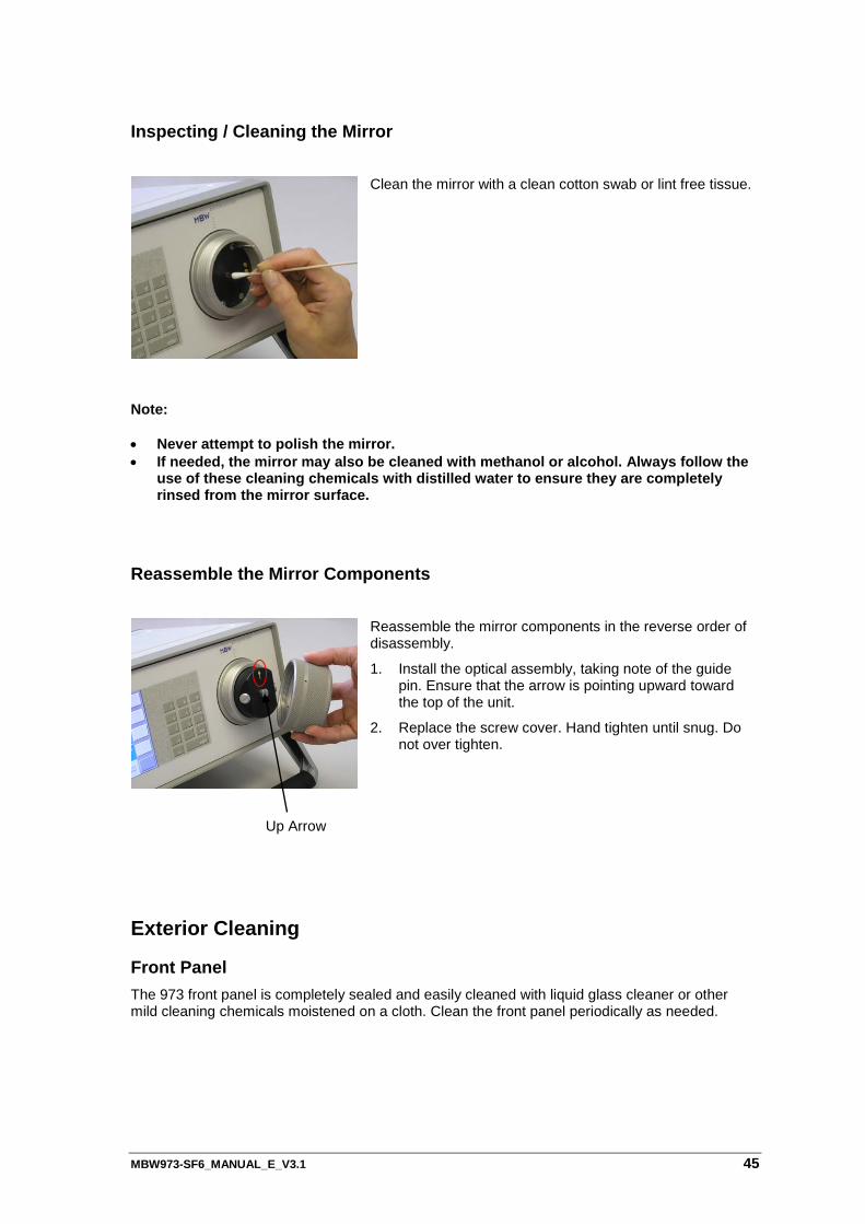
Clean the mirror with a clean cotton swab or lint free tissue.
Note: • Never attempt to polish the mirror. • If needed, the mirror may also be cleaned with methanol or alcohol. Always follow the
use of these cleaning chemicals with distilled water to ensure they are completely rinsed from the mirror surface.
Reassemble the Mirror Components
Reassemble the mirror components in the reverse order of disassembly.
1. Install the optical assembly, taking note of the guide pin. Ensure that the arrow is pointing upward toward the top of the unit.
2. Replace the screw cover. Hand tighten until snug. Do not over tighten.
Exterior Cleaning
Front Panel The 973 front panel is completely sealed and easily cleaned with liquid glass cleaner or other mild cleaning chemicals moistened on a cloth. Clean the front panel periodically as needed.
Up Arrow

46 MBW973-SF6_MANUAL_E_V3.1
MBW973-SF6_MANUAL_E_V3.1 47
Specifications
We reserve the right to change design or technical data without notice.
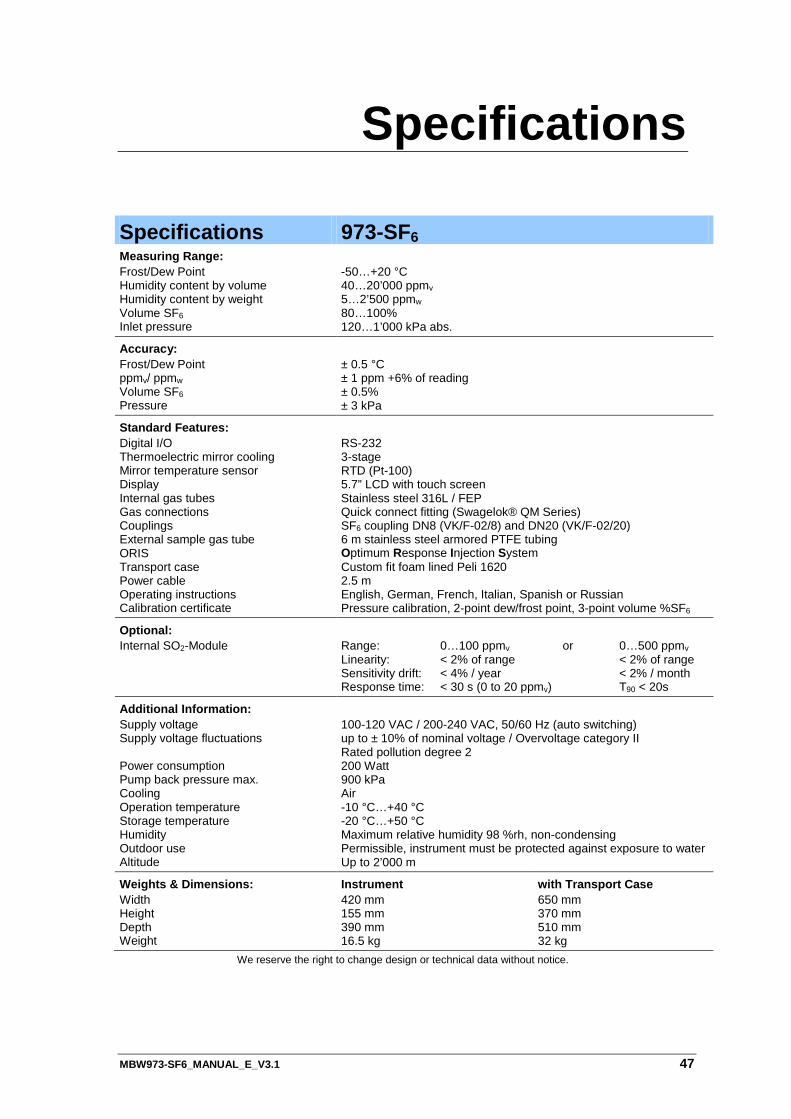
Specifications 973-SF6 Measuring Range: Frost/Dew Point Humidity content by volume Humidity content by weight Volume SF6 Inlet pressure
-50…+20 °C 40…20’000 ppmv 5…2’500 ppmw 80…100% 120…1’000 kPa abs.
Accuracy: Frost/Dew Point ppmv/ ppmw Volume SF6 Pressure
± 0.5 °C ± 1 ppm +6% of reading ± 0.5% ± 3 kPa
Standard Features: Digital I/O Thermoelectric mirror cooling Mirror temperature sensor Display Internal gas tubes Gas connections Couplings External sample gas tube ORIS Transport case Power cable Operating instructions Calibration certificate
RS-232 3-stage RTD (Pt-100) 5.7” LCD with touch screen Stainless steel 316L / FEP Quick connect fitting (Swagelok® QM Series) SF6 coupling DN8 (VK/F-02/8) and DN20 (VK/F-02/20) 6 m stainless steel armored PTFE tubing Optimum Response Injection System Custom fit foam lined Peli 1620 2.5 m English, German, French, Italian, Spanish or Russian Pressure calibration, 2-point dew/frost point, 3-point volume %SF6
Optional: Internal SO2-Module
Range: 0…100 ppmv or 0…500 ppmv Linearity: < 2% of range < 2% of range Sensitivity drift: < 4% / year < 2% / month Response time: < 30 s (0 to 20 ppmv) T90 < 20s
Additional Information: Supply voltage Supply voltage fluctuations Power consumption Pump back pressure max. Cooling Operation temperature Storage temperature Humidity Outdoor use Altitude
100-120 VAC / 200-240 VAC, 50/60 Hz (auto switching) up to ± 10% of nominal voltage / Overvoltage category II Rated pollution degree 2 200 Watt 900 kPa Air -10 °C…+40 °C -20 °C…+50 °C Maximum relative humidity 98 %rh, non-condensing Permissible, instrument must be protected against exposure to water Up to 2’000 m
Weights & Dimensions: Width Height Depth Weight
Instrument 420 mm 155 mm 390 mm 16.5 kg
with Transport Case 650 mm 370 mm 510 mm 32 kg