mazatrol fusion 640 service procedures -...
TRANSCRIPT

Service Procedures
Mazatrol Fusion 640Publication # C640RA1010E
CAUTION
This Manual is published to assist experienced personnel on the operation, maintenanceand/or programming of Mazak machine tools.
All Mazak machine tools are engineered with a number of safety devices to protectpersonnel and equipment from injury or damage. Operators should not, however, relysolely upon these safety devices, but should operate the machine only after fullyunderstanding what special precautions to take by reading the following documentationthoroughly.
Do not attempt to operate or perform maintenance / repair on the machine without athorough understanding of the actions about to be taken. If any question exists, contactthe nearest Mazak service center for assistance.
Certain covers, doors or safety guards may be open or removed to more clearly showmachine components. These items must be in place before operating the machine.Failure to comply with this instruction may result in serious personal injury or damage tothe machine tool.
This manual was considered complete and accurate at the time of publication, however,due to our desire to constantly improve the quality and specification of all Mazakproducts, it is subject to change or modification.

Notes:

Mazatrol Fusion 640 Service Procedures 640........................................
SAFETY PRECAUTIONS S-1....................................................................
LOCKOUT PROCEDURE S-4...............................................................
INSTALLATION PRECAUTIONS S-5....................................................
WARNINGS S-8.....................................................................................
DOOR INTERLOCK SAFETY SPECIFICATION S-11.............................Switch Panel Diagram S-12.................................................................
M640_Com. 1.........................................................................................
M640 Data Xfer 3Digit For M640T, 1.....................................................
M640 Data Xfer 3Digit For M640M, 1....................................................
M640_COM_HYPERTERMINAL. 1........................................................
M640_PrintKey_Instructions. 1............................................................
M640 Printer Information. 1..................................................................
M640 Printer Setup Print To File 1.......................................................
M640_Macro_Print. 1.............................................................................
M640 Ethernet Network Logon Bypass. 1...........................................
M640 Ethernet Card Instruction ?........................................................
M640 SW Regional ExplanationB3a and C0. 1....................................
M640 Service Drive Directory. 1...........................................................
FORMS 35................................................................................................
640M Version Form 35.........................................................................
640MT Version Form 18.......................................................................
640T Version Form 18..........................................................................
640 NC Software Claim Report 640.......................................................
M640 Software -B Version Main Update Procedure. 1.......................
M640 Re-Initialization Procedure. 1.....................................................

M640 Data Save Procedure. 1..............................................................
M640 Parameter Servo Spindle O PitchError. 1..................................
M640 Servo Update Procedure. 1........................................................
M640 Maintenance Display. 1...............................................................
M640 PLC Display Explanation. 1........................................................
M640 PLC Corruption Recovery. 1.......................................................
M640 PLC Saving Floppy. 1..................................................................
M640 PLC Update Floppy. 1.................................................................
M640 PLC LPC File Explanation. 1......................................................
M640 Floppy Installation Instruction. 1...............................................
M640 Hard Disk Replacement Procedure. 1........................................
M640 HR841 Installation. 1...................................................................
M640 Option Installation Procedure. 1................................................
M640 SanDisk Explanation. 1...............................................................
M640 Option Overload Detect 1...........................................................
M640 Data Save SRAM Procedure. 1...................................................
M640 Data Save BUSCON. 1.................................................................
INDEX 1..................................................................................................

SAFETY PRECAUTIONSThe machine is provided with a number of safetydevices to protect personnel and equipment frominjury and damage. Operators should not,however, rely solely upon these safety devices,but should operate the machine only after fullyunderstanding what special precautions to take byreading the following documentation thoroughly.
• BASIC OPERATING PRACTICESDANGER:
1) Some control panels, transformers, motors,junction boxes and other parts have highvoltage terminals. These should not be touchedor a severe electric shock may be sustained.
2) Do not touch any switches with wet hands.This too, can produce an electric shock.
WARNING:
1) The emergency stop pushbutton switchlocation should be well known, so that it can beoperated at any time without having to look forit.
2) Before replacing a fuse, turn off the mainincoming power switch to the machine.
3) Provide sufficient working space to avoidhazardous falls.
4) Water or oil can make floors slippery andhazardous. All floors should be clean and dryto prevent accidents
5) Do not operated any switch without a thoroughunderstanding of the actions about to be taken.
6) Avoid accidental operation of switches.7) Work benches near the machine must be
strong enough to hold materials placed onthem to prevent accidents. Articles should beprevented from slipping off the bench surface.
8) If a job is to be done by two or more persons,coordinating signals should be given at eachstep of the operation. The next step should notbe taken unless a signal is given andacknowledged.
CAUTION:
1) In the event of power failure, turn off the maincircuit breaker immediately.
2) Use the recommended hydraulic oils, lubricantsand grease or acceptable equivalents.
3) Replacement fuses should have the propercurrent ratings.
4) Protect the NC unit, operating panel, electriccontrol panel, etc. from shocks, since thiscould cause a failure or malfunction.
5) Do not change parameters or electricalsettings. If changes are unavoidable, recordthe values prior to the change so that they canbe returned to their original settings, ifnecessary.
6) Do not deface, scratch or remove any cautionplate. Should it become illegible or missing,order another caution plate from the supplier,specifying the part number shown at the lowerright corner of the plate.
• BEFORE POWERING UPDANGER:
Cables, cords or electric wires whose insulationis damaged can produce current leaks andelectric shocks. Before using, check theircondition.
WARNING:
1) Be sure the instruction manual and theprogramming manual are fully understoodbefore operating the machine. Every functionand operating procedure should be completelyclear.
2) Use approved oil resistant safety shoes, safetygoggles with side covers, safe clothes, andother safety protection required.
3) Close all NC unit, operating panel, electriccontrol panel doors and covers.
CAUTION:
1) The power cable from the factory feeder switchto the machine main circuit breaker shouldhave a sufficient sectional area to handle theelectric power used.
2) Cables which must be laid on the floor must beprotected from hot chips, by using rigid orother approved conduit, so that short-circuitswill not occur.
3) Before first time operation of the machine afterunpacking it or from being idle for a long periodof time (several days or more), each slidingpart must be sufficiently lubricated. To do so,push and release the pump button severaltimes until the oil seeps out on the slidingparts. The pump button has a return spring, sodo not force it to return.
4) Oil reservoirs should be filled to indicatedlevels. Check and add oil, if needed.
5) For lubrication points, oil specification andappropriate levels, see the various instructionplates.
6) Switches and levers should operate smoothly.Check that they do.
7) When powering the machine on, turn on theswitches in the following order: first the factoryfeeder switch, then the machine main circuitbreaker, and then the control power on switchlocated on the operating panel.
8) Check the coolant level, and add coolant, ifneeded.
S-1

• AFTER CONTROL POWER IS TURNED ONCAUTION:
When the control power “ON” switch on theoperating panel is on, the "READY" lamp onthe operating panel should also be on (check tosee that it is).
• ROUTINE INSPECTIONSWARNING:
When checking belt tensions, do not get yourfingers caught between the belt and pulley.
CAUTION:
1) Check pressure gages for proper readings.2) Check motors, gear boxes and other parts for
abnormal noises.3) Check the motor lubrication, and sliding parts
for evidence of proper lubrication.4) Check safety covers and safety devices for
proper operation.5) Check belt tensions. Replace any set of belts
that have become stretched with a freshmatching set.
• WARM UPCAUTION:
1) Warm up the machine, especially the spindleand feed shaft, by running the machine for 10to 20 minutes at about one-half or one-third themaximum speed in the automatic operationmode.
2) The automatic operation program should causeeach machine component to operate. At thesame time, check their operations.
3) Be particularly careful to warm up the spindlewhich can turn above 4000 rpm.If the machine is used for actual machiningimmediately after being started up following along idle period, the sliding parts may be worndue to the lack of oil. Also, thermal expansionof the machine components can jeopardizemachining accuracy. To prevent this condition,always make sure that the machine is warmedup.
• PREPARATIONSWARNING:
1) Tooling should conform to the machinespecifications, dimensions and types.
2) Replace all seriously worn tools with new onesto prevent injuries.
3) The work area should be adequately lighted tofacilitate safety checks.
4) Tools and other items around the machine orequipment should be stored to ensure goodfooting and clear aisles.
5) Do not place tools or any other items on theheadstock, turret, covers and similar places(For T/M).
CAUTION:
1) Tool lengths should be within specifiedtolerances to prevent interference.
2) After installing a tool, make a trial run.
• OPERATIONWARNING:
1) Do not work with long hair that can be caughtby the machine. Tie it back, out of the way.
2) Do not operate switches with gloves on. Thiscould cause mis-operation.
3) Whenever a heavy workpiece must be moved,if there is any risk involved, two or more peopleshould work together.
4) Only trained, qualified workers should operateforklift trucks, cranes or similar equipment andapply slings.
5) Whenever operating a forklift truck, crane orsimilar equipment, special care should be takento prevent collisions and damage to thesurroundings.
6) Wire ropes or slings should be strong enoughto handle the loads to be lifted and shouldconform to the mandatory provisions.
7) Grip workpieces securely.8) Stop the machine before adjusting the coolant
nozzle at the tip.9) Never touch a turning workpiece in the spindle
with bare hands, or in any other way.10) To remove a workpiece from the machine other
than by a pallet changer, stop the tool andprovide plenty of distance between theworkpiece and the tool (for M/C).
11) While a workpiece or tool is turning, do notwipe it off or remove chips with a cloth or byhand. Always stop the machine first and thenuse a brush and a sweeper.
12) Do not operate the machine with the chuck andfront safety covers removed (For T/M).
13) Use a brush to remove chips from the tool tip,do not use bare hands .
14) Stop the machine whenever installing orremoving a tool.
15) Whenever machining magnesium alloy parts,wear a protective mask.
S-2

CAUTION:
1) During automatic operation, never open themachine door. Machines equipped with thedoor interlock will set the program to singlestep.
2) When performing heavy-duty machining,carefully prevent chips from being accumulatedsince hot chips from certain materials cancause a fire.
• TO INTERRUPT MACHININGWARNING:
When leaving the machine temporarily aftercompleting a job, turn off the power switch onthe operation panel, and also the main circuitbreaker.
• COMPLETING A JOBCAUTION:
1) Always clean the machine or equipment.Remove and dispose of chips and clean coverwindows, etc.
2) Make sure the machine has stopped running,before cleaning.
3) Return each machine component to its initialcondition.
4) Check the wipers for breakage. Replacebroken wipers.
5) Check the coolant, hydraulic oils and lubricantsfor contamination. Change them if they areseriously contaminated.
6) Check the coolant, hydraulic oil and lubricantlevels. Add if necessary.
7) Clean the oil pan filter.8) Before leaving the machine at the end of the
shift, turn off the power switch on the operatingpanel, machine main circuit breaker and factoryfeeder switch in that order.
• SAFETY DEVICES1) Front cover, rear cover and coolant cover.2) Chuck barrier, tail barrier and tool barrier (NC
software).3) Stored stroke limit (NC software).4) Emergency stop pushbutton switch.
• MAINTENANCE OPERATION PREPARATIONS1) Do not proceed to do any maintenance
operation unless instructed to do so by theforeman.
2) Replacement parts, consumables (packing, oilseals, O rings, bearing, oil and grease, etc.)Should be arranged in advance.
3) Prepare preventive maintenance and recordmaintenance programs.
CAUTION:
1) Thoroughly read and understand the safetyprecautions in the instruction manual.
2) Thoroughly read the whole maintenancemanual and fully understand the principles,construction and precautions involved.
• MAINTENANCE OPERATIONDANGER:1) Those not engaged in the maintenance work
should not operate the main circuit breaker orthe control power "ON" switch on theoperating panel. For this purpose, "Do notTouch the Switch, Maintenance Operation inProgress!" or similar warning should beindicated on such switches and at any otherappropriate locations. Such indication shouldbe secured by a semi-permanent means in thereading direction.
2) With the machine turned on, any maintenanceoperation can be dangerous. In principle, themain circuit breaker should be turned offthroughout the maintenance operation.
WARNING:
1) The electrical maintenance should be done bya qualified person or by others competent to dothe job. Keep close contact with theresponsible person. Do not proceed alone.
2) Overtravel limit and proximity switches andinterlock mechanisms including functional partsshould not be removed or modified.
3) When working at a height, use steps or ladderswhich are maintained and controlled daily forsafety.
4) Fuses, cables, etc. made by qualifiedmanufacturers should be employed.
• BEFORE OPERATION & MAINTENANCE BEGINSWARNING:
1) Arrange things in order around the section toreceive the maintenance, including workingenvironments. Wipe water and oil off parts andprovide safe working environments.
2) All parts and waste oils should be removed bythe operator and placed far enough away fromthe machine to be safe.
CAUTION:
1) The maintenance person should check that themachine operates safely.
2) Maintenance and inspection data should berecorded and kept for reference.
000X717-KY 11/98
S-3
ALWAYS TURN THE MAIN CIRCUIT BREAKER TO THE “OFF” POSITION & USE AN APPROVED
LOCKOUT DEVICE WHEN COMPLETING MAINTENANCE OR REPAIRS.
THE LOCKOUT PROCEDURE THAT FOLLOWS IS INTENDED TO SAFEGUARD PERSONNEL &
EQUIPMENT DURING MAINTENANCE OPERATIONS, AND, REPRESENTS THE MINIMUM
REQUIREMENTS. ANY ACTION SHOULD BE PRECEDED BY A “HAZARD ANALYSIS” TO DETERMINE
ANY ADDITIONAL SAFETY PRECAUTIONS THAT MAY BE NECESSARY TO ENSURE THE SAFETY OF
PERSONNEL AND EQUIPMENT.
NOTE: USE OF THE FOLLOWING LOCKOUT PROCEDURE IS MANDATORY WHEN COMPLETING
MAINTENANCE OR REPAIRS.
LOCKOUT PROCEDURE
1) THE LOCKOUT PROCESS MUST BE PERFORMED BY AUTHORIZED PERSONNEL ONLY.
2) INFORM ALL EFFECTED PERSONNEL OF YOUR INTENT TO LOCKOUT AND SERVICE THE
SPECIFIED MACHINE.
3) SHUT OFF MACHINE POWER USING NORMAL SHUT DOWN PROCEDURES.
4) TURN OFF THE MACHINE AND INDIVIDUAL BUILDING CIRCUIT BREAKERS. MAKE SURE ALL
STORED ELECTRICAL ENERGY IS RELIEVED. (EG: SPINDLE & AXIS SERVO CONTROLLERS)
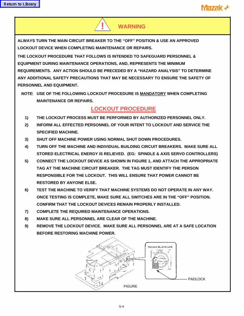
5) CONNECT THE LOCKOUT DEVICE AS SHOWN IN FIGURE 1, AND ATTACH THE APPROPRIATE
TAG AT THE MACHINE CIRCUIT BREAKER. THE TAG MUST IDENTIFY THE PERSON
RESPONSIBLE FOR THE LOCKOUT. THIS WILL ENSURE THAT POWER CANNOT BE
RESTORED BY ANYONE ELSE.
6) TEST THE MACHINE TO VERIFY THAT MACHINE SYSTEMS DO NOT OPERATE IN ANY WAY.
ONCE TESTING IS COMPLETE, MAKE SURE ALL SWITCHES ARE IN THE “OFF” POSITION.
CONFIRM THAT THE LOCKOUT DEVICES REMAIN PROPERLY INSTALLED.
7) COMPLETE THE REQUIRED MAINTENANCE OPERATIONS.
8) MAKE SURE ALL PERSONNEL ARE CLEAR OF THE MACHINE.
9) REMOVE THE LOCKOUT DEVICE. MAKE SURE ALL PERSONNEL ARE AT A SAFE LOCATION
BEFORE RESTORING MACHINE POWER.
FIGURE
WARNING
a a a
a a a
a a a
a a a
a a a!
PADLOCK
S-4
INSTALLATION PRECAUTIONSThe following subjects outline the items thatdirectly affect the machine installation and start-up. To ensure an efficient and timely installation,please follow these recommendations beforecalling to schedule a service engineer.
• ENVIRONMENTAL REQUIREMENTSAvoid the following places for installing themachine:
1) Avoid exposure to direct sunlight and/or near aheat source, etc. Ambient temperature duringoperation: 0° thru 45°C (32°F to 113°F).
2) Avoid areas where the humidity fluctuatesgreatly and/or if high humidity is present;normally 75% and below in relative humidity. Ahigher humidity deteriorates insulation andmight accelerate the deterioration of parts.
3) Avoid areas that are especially dusty and/orwhere acid fumes, corrosive gases and salt arepresent.
4) Avoid areas of high vibration.5) Avoid soft or weak ground (minimum load
bearing capacity of 1025 lbs./ft 2)
• FOUNDATION REQUIREMENTSFor high machining accuracy, the foundationmust be firm and rigid. This is typicallyaccomplished by securely fastening themachine to the foundation with anchor bolts. Inaddition, the depth of concrete should be asdeep as possible (minimum 6 - 8 inches). Notethe following:
1) There can be no cracks in the foundationconcrete or surrounding area.
2) Vibration proofing material (such as asphalt)should be put all around the concrete pad.
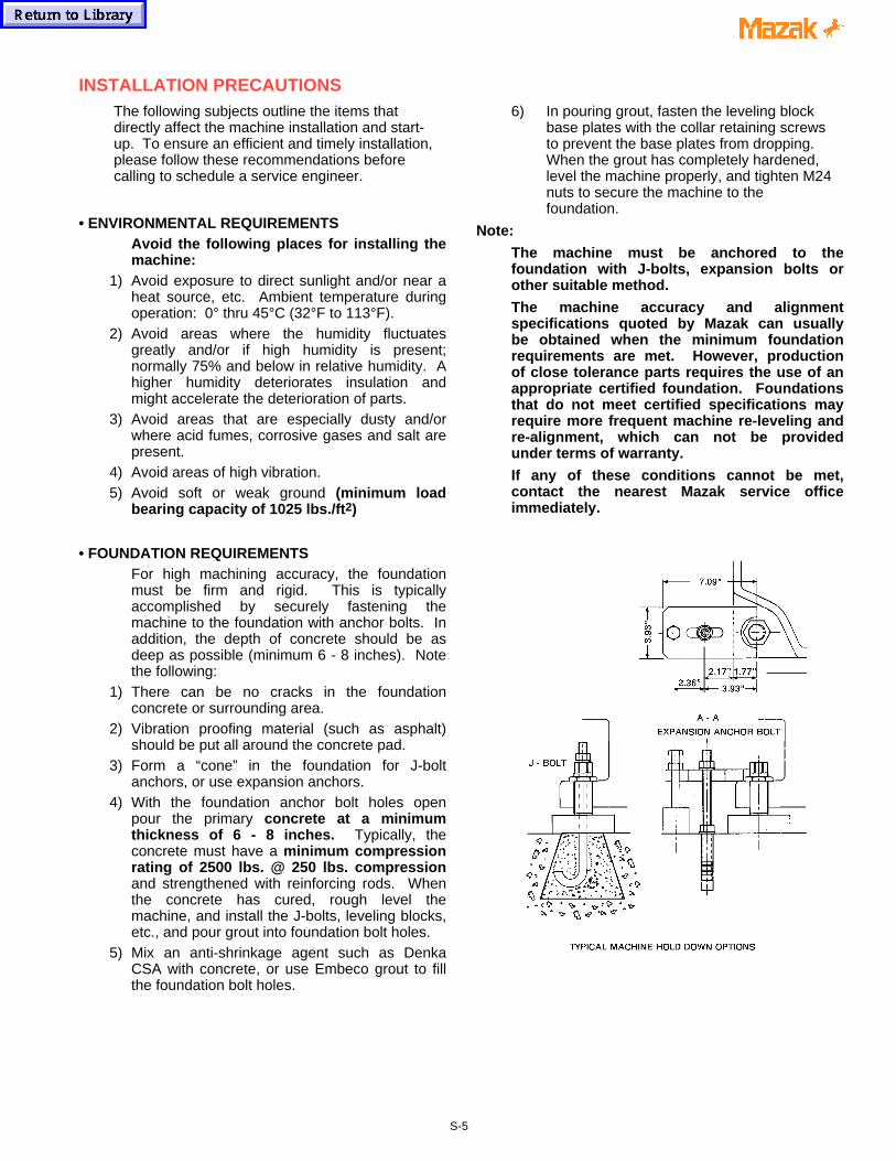
3) Form a “cone” in the foundation for J-boltanchors, or use expansion anchors.
4) With the foundation anchor bolt holes openpour the primary concrete at a minimumthickness of 6 - 8 inches. Typically, theconcrete must have a minimum compressionrating of 2500 lbs. @ 250 lbs. compressionand strengthened with reinforcing rods. Whenthe concrete has cured, rough level themachine, and install the J-bolts, leveling blocks,etc., and pour grout into foundation bolt holes.
5) Mix an anti-shrinkage agent such as DenkaCSA with concrete, or use Embeco grout to fillthe foundation bolt holes.
6) In pouring grout, fasten the leveling blockbase plates with the collar retaining screwsto prevent the base plates from dropping. When the grout has completely hardened,level the machine properly, and tighten M24nuts to secure the machine to thefoundation.
Note:
The machine must be anchored to thefoundation with J-bolts, expansion bolts orother suitable method.
The machine accuracy and alignmentspecifications quoted by Mazak can usuallybe obtained when the minimum foundationrequirements are met. However, productionof close tolerance parts requires the use of anappropriate certified foundation. Foundationsthat do not meet certified specifications mayrequire more frequent machine re-leveling andre-alignment, which can not be providedunder terms of warranty.
If any of these conditions cannot be met,contact the nearest Mazak service officeimmediately.
S-5

• WIRING
1) Use only electrical conductors withperformance ratings equivalent or superior.
2) Do not connect any power cables for deviceswhich can cause line noise to the powerdistribution panel, such as arc welders and highfrequency machinery.
3) Arrange for a qualified electrician to connectthe power lines.
4) Incoming supply voltage should not deviatemore than ±10% of specified supply voltage.
5) Source frequency should be±2 Hz of nominalfrequency.
[ CAUTION ]
VERIFY THE ACTUAL MACHINE ELECTRICAL
POWER REQUIREMENT AND THE MAIN
TRANSFORMER RATING (IF APPLICABLE), AS
WELL AS THE LOCAL ELECTRICAL CODE
BEFORE SIZING AND INSTALLING THE
INCOMING POWER WIRING.
PLEASE SEE THE ADDITIONAL CAUTIONS ON
THE FOLLOWING PAGE.
• GROUNDING
1) An isolated earth ground with a resistance toground of less than 100 ohms is required.Typically, a 5/8” copper rod, 8 feet long, andno more than 5 feet from the machine, issufficient. Building grounds or multiplemachines grounded to the same ground rod,are not acceptable.
2) The wire size should be greater than AWG(American Wire Gauge) No. 5 and SWG(British Legal Standard Wire Gauge) No. 6.
Desirable Independent Grounding:
N C Earth resistance:Machine Less than 100 ohms
Common Grounds:
Resistance to ground= 100 ÷ the number ofdevices connected tothe grounding (ohms)
Note: Never ground equipment as shown below:
000X713-KY 11/98
S-6

A step-down transformer is optional on some machine models. Be certain to
verify the transformer Kva rating (where applicable), as well as local electrical
code requirements before sizing and installing the incoming power wiring.
Machines not equipped with a main transformer are wired for 230 VAC, 3 phase.
The end user must supply a step-down transformer where factory electrical
power varies more than ± 10% of the 230 VAC rating.
NOTE:
Step-down or voltage regulating transformers are external (peripheral) to the
machine tool and are considered the primary input line (source) for the machine.
Local electrical code or practice may require a circuit breaker or other switching
device for the isolation of electrical power when this type of transformer is used.
In such cases, the machine tool end user is required to supply the necessary
circuit breaker or switching device.
FAILURE TO COMPLY CAN RESULT IN PERSONAL INJURY AND DAMAGE TO THEMACHINE. IF ANY QUESTION EXISTS, CONTACT THE NEAREST MAZAK SERVICECENTER FOR ASSISTANCE.
CAUTION!
S-7

MAZATROL CNC CONTROLLERS PROVIDE PARAMETER SETTINGS TO LIMIT SPINDLERPM. THESE SETTINGS ARE BASED ON THE MAXIMUM SPEED SPECIFIED BY THECHUCK/ACTUATOR MANUFACTURER.
MAKE SURE TO SET THESE PARAMETERS ACCORDING TO CHUCK SPECIFICATIONWHEN INSTALLING A CHUCKING PACKAGE. ALSO, STAMP THE MAXIMUM SPINDLERPM ON THE CHUCK IDENTIFICATION PLATE LOCATED ON THE MACHINE TOOLCOVERS.
REFERENCE THE CNC PARAMETER MANUAL SUPPLIED WITH THE SPECIFIC MACHINETOOL TO IDENTIFY THE REQUIRED PARAMETERS TO CHANGE.
FAILURE TO COMPLY WITH THESE INSTRUCTIONS COULD RESULT IN DAMAGE TOTHE MACHINE, SERIOUS INJURY OR DEATH.
IF ANY QUESTIONS EXIST, CONTACT THE NEAREST MAZAK SERVICE CENTER FORASSISTANCE.
S-8
MAZAK MACHINES ARE ENGINEERED WITH A NUMBER OF SAFETY DEVICES TOPROTECT PERSONNEL AND EQUIPMENT FROM INJURY AND DAMAGE.
DO NOT REMOVE, DISCONNECT, BYPASS OR MODIFY ANY LIMIT SWITCH, INTERLOCK,COVER, OR OTHER SAFETY FEATURE IN ANY WAY, EITHER MECHANICALLY ORELECTRICALLY.
FAILURE TO COMPLY WITH THESE INSTRUCTIONS COULD RESULT IN DAMAGE TOTHE MACHINE, SERIOUS INJURY OR DEATH.
IF ANY QUESTIONS EXIST, CONTACT THE NEAREST MAZAK SERVICE CENTER FORASSISTANCE.
WARNING!
WARNING!

MAZAK MACHINES ARE ENGINEERED WITH A NUMBER OF SAFETY DEVICES TOPROTECT PERSONNEL AND EQUIPMENT FROM INJURY AND DAMAGE.
MACHINE OPERATOR DOORS AND COVERS ARE DESIGNED TO WITHSTANDACCIDENTAL IMPACT OF A BROKEN INSERT WHERE A MAXIMUM WEIGHT INSERT ATMAXIMUM TOOL DIAMETER IS RUNNING AT MAXIMUM SPINDLE RPM
NEVER USE A CUTTING TOOL OR TOOL INSERT THAT EXCEEDS MACHINESPECIFICATIONS OR THAT OF A SPECIFIC TOOL HOLDER ITSELF, WHICHEVER IS LESS.THIS RESTRICTION APPLIES TO DIAMETER, WEIGHT, MAXIMUM SPINDLE RPM,MAXIMUM CUTTING TOOL ROTATION SPEED, ETC.
FOR COMPLETE SPECIFICATIONS, MAKE SURE TO REFERENCE OPERATION,MAINTENANCE AND DETAIL SPECIFICATION DOCUMENTATION SUPPLIED WITH THEMACHINE AND BY THE TOOLING MANUFACTURER.
NOTE: THE MAXIMUM INSERT WEIGHT FOR MAZAK MACHINES IS 20 gf. (0.04 lbs.).
FAILURE TO COMPLY WITH THESE INSTRUCTIONS COULD RESULT IN DAMAGE TOTHE MACHINE, SERIOUS INJURY OR DEATH.
IF ANY QUESTIONS EXIST, CONTACT THE NEAREST MAZAK SERVICE CENTER FORASSISTANCE.
S-9
WARNING!

WARNING!CONFIRM PROPER WORKPIECE FIXTURING/CLAMPING, TOOL SETUP AND THAT THEMACHINE DOOR IS SECURELY CLOSED BEFORE THE START OF MACHINING.
VERIFY ALL SAFETY PRECAUTIONS OUTLINED IN THIS MANUAL BEFORE USING THEFOLLOWING CUTTING CONDITIONS:
- CUTTING CONDITIONS THAT ARE THE RESULT OF THE MAZATROL FUSION 640AUTOMATIC CUTTING DETERMINATION FUNCTION
- CUTTING CONDITIONS SUGGESTED BY THE MACHINING NAVAGATION FUNCTION
- CUTTING CONDITIONS FOR TOOLS THAT ARE SUGGESTED TO BE USED BY THEMACHINING NAVAGATION FUNCTION
FAILURE TO COMPLY WITH THESE INSTRUCTIONS COULD RESULT IN DAMAGE TOTHE MACHINE, SERIOUS INJURY OR DEATH.
IF ANY QUESTIONS EXIST, CONTACT THE NEAREST MAZAK SERVICE CENTER FORASSISTANCE.
BEFORE STARTING OPERATION, CHECK THAT THE WORKPIECE IS SECURELY MOUNTEDIN A VISE OR A SUITABLE FIXTURE. BE CERTAIN THAT THE MOUNTING IS SUFFICIENTTO WITHSTAND CUTTING FORCES DURING WORKPIECE MACHINING.
FAILURE TO COMPLY WITH THESE INSTRUCTIONS COULD RESULT IN DAMAGE TOTHE MACHINE, SERIOUS INJURY OR DEATH.
IF ANY QUESTIONS EXIST, CONTACT THE NEAREST MAZAK SERVICE CENTER FORASSISTANCE.
WARNING!
S-10

CENGDB0551E
DOOR INTERLOCK SAFTY SPEC. Determined by YMW Eng. H.Q. ‘99/9/1Revised by YMC Prod. Eng. ’99.10.28
MACHINING CENTERSET UP SWITCH
DOOR MODEO (OFF) I (ON)
MANUAL Prohibit to move axis.Prohibit to start spindle running.Prohibit to operate manual ATC.Prohibit to operate manual Pallet Changer.Prohibit to run chip spiral conveyor.
Limit the rapid override. Max is 12%.Prohibit to run chip spiral conveyor.Can run spindle JOG.Can run spindle Orient.Can operate manual ATC.
OPEN
AUTO Prohibit cycle start.Prohibit to run chip spiral conveyor.
Prohibit cycle start.Prohibit to run chip spiral conveyor.
Door is always locked. Door lock can be released by pushing “DOOR UNLOCK SW” on operator panel.But, it can not release in operating ATC/Pallet changer/Axis/Spindle.
MANUAL
Prohibit to move axis.Prohibit to start spindle running.Prohibit to operate manual ATC.Prohibit to operate manual Pallet Changer.Prohibit to run chip spiral conveyor.
Limit the rapid override. Max is 12%.Chip spiral conveyor would stop.Can run spindle JOG.Can run spindle Orient.Can operate manual ATC.
Door is always locked. Door lock can be released by pushing “DOOR UNLOCK SW” on operator panel.But, it can not release in auto operation running except single block stop or feed hold stop or M00 programstop or M01 optional stop and spindle stop. If not, Alarm displayed “Door open invalid”.
CLOSEIV
OPEN
AUTO
If release the lock by note(*1), Alarm will occurthen stop the all motion.Chip spiral conveyor would stop.
Prohibit cycle start.Chip spiral conveyor would stop.
MANUAL No Limitation. No Limitation.CLOSE
AUTO No Limitation. Can not run auto operation.
TURNING CENTER SET UP SWITCH
DOOR MODE O (OFF) I (ON)
MANUAL
Can operate CHUCK, TAILSLEEVE ,STEADY REST for Loading workpiece.
Can NOT operate Spindle, Axis, Turret,Coolant, ToolEye, Partscatcher,Chip Conveyor.
Can operate CHUCK, TAILSLEEVE ,STEADY REST for Loading workpiece.
Can not operate Spindle running, butCan operate Spindle JOG and Spindle Orient.Limitation of speed for axis movement .(Override is 10% max.)1 step index only for turret.OPEN
AUTOCan operate CHUCK, TAILSLEEVE ,STEADY REST for Loading workpiece.Can not run Auto-operation.
Can operate CHUCK, TAILSLEEVE ,STEADY REST for Loading workpiece.Can not run Auto-operation.
CLOSE->
OPEN
MANUAL&
AUTO
Can not open the front door in Spindle running, Axis moving, Auto-running( Cycle start, Feed hold ) due toMechanical locking system. (Except Single Block Stop or M00 program stop or M01 optional stop)But, if release the lock by note(*1), Alarm will occur then stop the all motion.
MANUAL No Limitation. No Limitation.
CLOSE AUTO No Limitation. Can not run Auto-operation.
*1 : Door lock mechanism can not be released in machine stop by NC power OFF.If it is necessary to release the lock such as emergencies, the lock can be released by operating thesupplementary lock release mechanism of the main body of the safety door lock switch.
*2 : Override Limitation of Rapid speed of AXIS Machining Center : 12%. Turning Center : 10%.*3 : Chip Conveyor and Coolant should stop in the door open.
PED-EDS-001 S-11

CENGDB0551E
APPENDIX
SWITCH PANEL for M640M (Machining Center)
SWITCH PANEL for M640MT/T (Turning Center)
DOOR UNLOCKSWITCHMACHINE SET UP
SWITCH
PED-EDS-001 S-12

a aa aa aa aa aa aa aa aa aa aa aa aa aa aa aa aa aa aa aa aa aa aa aa aa aa aa aa aa aa aa aa aa aa aa aa aa aa aa aa aa aa aa aa aa aa aa aa aa aa aa aa aa aa aa aa aa aa aa aa aa aa aa aa aa aa aa aa aa aa aa aa aa aa aa aa aa aa aa aa aa aa aa aa aa aa aa aa aa aa aa aa aa aa aa aa aa aa aa aa aa aa aa aa aa aa aa aa aa aa aa aa aa aa aa aa aa aa aa aa aa aa aa aa aa aa aa aa aa aa aa aa aa aa aa aa aa aa aa aa aa aa aa aa aa aa aa aa aa aa aa aa aa aa aa aa aa aa aa aa aa aa aa aa aa aa aa aa aa aa aa aa aa aa aa aa aa aa aa aa aa aa aa aa aa aa a
Your opinion is important to enable us to issue documentation that will fit your needs.Thank you for taking the time to supply this information.
Machine Type: Machine Serial#: NC Type:
Customer: Reported By:
Address: Position:
Telephone#:
Manual Publication #:
How well is the documentation suited to your needs?
Were you able to find the necessary information easily?
How well are the manuals organized?
How easy are the manuals to understand?
Are the illustrations helpful?
Overall, how do you rate the documentation?
What did you like about the documentation? How can it be improved?
MACHINE DOCUMENTATIONCUSTOMER EVALUATION The Other Thoroughbred From Kentucky
Date:
Excellent Good Adequate Fair Poor
RETURN TO: MAZAK CorporationTechnical Publication Dept.8025 Production DriveFlorence, Kentucky 41042
a a a a a a a a a a a a a a a a a a a a a a a a a a a a a a a a a a a a a a a a a a a a a a a a a a a a a a a a a a a a a a a a a a a a a a a a a a a a a a a a a a a a a a a a a a a a a a a a a a a a a a a a a a a a a a a a a a a a a a a a a a a a a a a a a a a a a a a a
a a a a a a a a a a a a a a a a a a a a a a a a a a a a a a a a a a a a a a a a a a a a a a a a a a a a a a a a a a a a a a a a a a a a a a a a a a a a a a a a a a a a a a a a a a a a a a a a a a a a a a a a a a a a a a a a a a a a a a a a a a a a a a a a a a a a a a a a
a a a a a a a a a a a a a a a a a a a a a a a a a a a a a a a a a a a a a a a a a a a a a a a a a a a a a a a a a a a a a a a a a a a a a a a a a a a a a a a a a a a a a a a a a a a a a a a a a a a a a a a a a a a a a a a a a a a a a a a a a a a a a a a a a a a a a a a a
SF-202Xa

Notes:

M640_com.doc 12/23/99 1:07 PM 1
M640_Com.doc revised 11/3/1999Questions arise as to what can be read into M640 control.Below shows for the M640T, not M640MT control.It is impossible to upload any Mazatrol programs to the M640MTfrom T32,Tplus, or M640T.
Note: It is impossible to save from any M640 control and load aMazatrol program to earlier control type.
M640T 1) Loading Mazatrol programs via CMT to M640T. A) From T32 -- Impossible B) From Tplus- Possible, some edit may be necessary. 2) Loading Mazatrol programs via Computer I/O to M640T. A) From T32 – Impossible, computer I/O doesn’t exist for T32. B) From Tplus – Possible, however, upgrade to B2 software. See M640_Data_Xfer_3Digit_For_M640T.doc for more information. 3) Loading Mazatrol programs via DcCode control to M640T. A) From T32,TPlus --- Impossible
M640M – Machining center control. 1) Loading Mazatrol programs via CMT to M640M. A) From M32,M32B,M32A -- Impossible B) From Mplus- Possible, some edit may be necessary.
2) Loading Mazatrol programs via Computer I/O to M640M. A) From M32,M32B,M32A – Impossible, computer I/O doesn’t exist for M32 series. B) From Mplus – Possible, some edit on CNC may be necessary. See M640_Data_Xfer_3Digit_For_M640M.doc for more information. 3) Loading Mazatrol programs via DcCode control to M640M. A) From M32,M32A,M32B or Mplus --- Impossible

M640_Data_Xfer_3Digit_For_M640T.doc 12/23/99 1:10 PM 1
M640 Data Xfer 3Digit For M640T, revised 11/03/1999
For M640MT and T, B2c gives the user the capability to save programsin 3-digit G-code format.
Note: To upload Tplus programs saved in Computer I/Oformat, see Appendix-A at end of this procedure.
First, update to B2c(Main-B,369W001-B2c) or greater.Next, set parameter P105 bit 6 to 1 (Example: P105: 0100 0000) Keep the other bits same setting.
To Save: 1) Select Data I/O. 2) Press HardDisk and then Dir Select and enter in directory. 3) Press NC -> HD Save. 4) Press Text Format to highlight button. Leave alone if highlighted. 5) Select data to save and press Start. 6) If you wish to change to different folder than T_Backup/Other, select “Setup” and enter in the new path(see figure 1).

M640_Data_Xfer_3Digit_For_M640T.doc 12/23/99 1:10 PM 2
figure 1 Shows where Text Format button was added. If you wishto view the actual saving of each file, go to “View” and click on“I/O Status”.

M640_Data_Xfer_3Digit_For_M640T.doc 12/23/99 1:10 PM 3
figure2 Shows 3-digit format of the saved program data. Takenfrom an Igx200sy on a MT control. Filename suffix is T6p forM640T control.
APPENDIX A
M640_Data_Xfer_3Digit_For_M640T.doc 12/23/99 1:10 PM 4
1) The Tplus programs will normally have a .txt or .maz extension for Ethernet saved. Change to .t6p extension after doing following changes. Note: You cannot use .i6p as this is for a M64O MT controlledmachine and no Tplus is equivalent.
2) When editing, the files may be to big to use NotePad. Use an Ascii file editor like TextPad32(www.textpad.com). It can handle large Ascii files. Do not use WordPad or Word as they can insert garbage and WordPad will cut off a large file without alerting you to this fact.
3) Delete % from beginning of program. In some cases you may need toremove program number, and description in parenthesis.
4) Save the file with .T6p extension and put into the directory selectedabove or create Test directory in c:\T_Backup\Other\Test. Or you canput on a floppy in a given directory. Or you can useBrowse button and go to an external computer if part of Network. Do not put directly into c:\T_Machine Programs. Programs must go thru control(Data I//O) and into this directory.
5) Go to the NC side and thru use of DATA I/O load the file(s) into the NC. Select directory you saved them into. You will only see directories under c:\T_Backup\Other\ if select Hard Drive. If file is saved on floppy, use the Floppy and select directory.
Note: When saving a file to a directory, the control will first Delete any other files in that directory, just saving in CMT mode. So create a new directory if saving new files.

M640_Data_Xfer_3Digit_For_M640M.doc 1
M640 Data Xfer 3Digit For M640M, revised 11/03/1999
For M640M, Main-B B2a gives the user the capability to save programsin 3-digit G-code format.
To read an existing MPlus program saved via Computer I/O or Ethernet 3-digit mode, some small changes may be needed. See Appendix A at end of this procedure.
First, update to B2a(Main-B,360W001-B2a) or greater.Next, set parameter F82 bit 7 to 1 (Example: F82: 1000 0000) Keep the other bits same setting.
To Save: 1) Select Data I/O. 2) Press HardDisk and then Dir Select and enter in directory. 3) Press NC -> HD Save. 4) Press Text Format to highlight button. Leave alone if highlighted. 5) Select data to save and press Start. 6) If you wish to change to different folder than M_Backup/Other, select “Setup” and enter in new path(see figure1).

M640_Data_Xfer_3Digit_For_M640M.doc 2
figure 1 Shows where Text Format button was added. If you wishto view the actual saving of each file, go to “View” and click on“I/O Status”.

M640_Data_Xfer_3Digit_For_M640M.doc 3
figure2 Shows 3-digit format of the saved program data. Takenfrom an M640M control.
APPENDIX A

M640_Data_Xfer_3Digit_For_M640M.doc 4
1) The Mplus programs will normally have a .txt or .maz extension for Ethernet saved. Change to .m6p extension after doing following changes.
2) When editing, the files may be to big to use NotePad. Use an Ascii file editor like TextPad32(www.textpad.com). It can handle large Ascii files. Do not use WordPad or Word as they can insert garbage and WordPad will cut off a large file without alerting you to this fact.
3) Delete % from beginning of program. In some cases you may need toremove program number, and description in parenthesis.
4) Save the file with .M6p extension and put into the directory selectedabove or create Test directory in c:\MC_Backup\Other\Test. Or you canput on a floppy in a given directory. You can also use the Browse buttonfor Network. Do not put directly into c:\MC_Machine Programs. Programs must go thru control(Data I//O) and into this directory.
5) Go to the NC side and thru use of DATA I/O loaded the file(s) into the NC. Select directory you saved them into. You will only see directories under c:\MC_Backup\Other\ if select Hard Drive. If file is saved on floppy, use the Floppy and select directory.
Note: When saving a file to a directory, the control will first Delete any other files in that directory, just saving in CMT mode. So create a new directory if saving new files.

M640 COM Hyperterminal.doc Created on 02/26/99 6:30 AM1
M640_COM_HYPERTERMINAL.doc
Quick Reference Guide Hyper TerminalSetup
(The Underlined text below are Hyper Links. Click on them to jump to that section)
1. Beginning of Hyper Terminal Setup Procedure.
2. Cable Configurations
3. Fusion Parameter Setup
4. Mplus Parameter Setup
5. Tplus Parameter Setup
6. TroubleShooting Tips
WARNING!!!!!!!!!!!!!!THE VERSION OF HYPERTERMINAL THAT SHIPS WITH ALLVERSIONS OF WINDOWS 95 HAS PROBLEMS WITH ASCII FILETRANSFERS. BEFORE YOU START THIS PROCEDURE YOUSHOULD DOWNLOAD THE FREE UPGRADE AThttp://www.winmag.com/software/1997/0701/07share.htm#a2
IF YOU HAVE THE LATEST VERSION THE GLOBE ON THEHILGRAEVE LOGO WINDOW THAT POPS UP WHEN YOUSTART HYPERTERMINAL WILL ROTATE.

M640 COM Hyperterminal.doc Created on 02/26/99 6:30 AM2
Hyperterminal For Windows95 To Mazatrol Control Setup
Select PropertiesProperties will allow you to set the Hyper Terminal communications settings to workproperly with the Mazak Machine Tool.
You will need to know some information about your computer before going any furtherwith the setup. A few points are as follows:
Where are the serial ports on your computer? Computers have a (9-pin port) or a (25-pin port) and both are male connectors. Many people confuse the parallel port with theserial. The parallel port is a female port.
Is the serial port free to be used? Many times a mouse may be connected to the port oran internal modem may be set to that port number (COM1 or COM2).

M640 COM Hyperterminal.doc Created on 02/26/99 6:30 AM3
To Top

M640 COM Hyperterminal.doc Created on 02/26/99 6:30 AM4
Select the Port
The port must be free to be used. Conflicts with a mouse driver or other devices cancost you a lot of time.
Selecting the speed that the computer will transfer
Click the "Configure" button, and you will see the following screen……

M640 COM Hyperterminal.doc Created on 02/26/99 6:30 AM5
Select the same settings as above and click "OK".
You have now told your computer the speed of the port. The computer settings are notthe same as those of the machine. The computer is set to (7) data bits and the machineis set to (8) data bits.
Selecting terminal settings
The next step is to tell Hyper Terminal how to format the programs that it will besending or capturing. This is done through the Settings window, which you will see onthe next page……..

M640 COM Hyperterminal.doc Created on 02/26/99 6:30 AM6
Select the same settings as above.
Next click the "Terminal Setup" button, and you will see the window on the nextpage…..

M640 COM Hyperterminal.doc Created on 02/26/99 6:30 AM7
Make the settings the same as above, and then click "OK"
Next click the "Ascii Setup" button and you will see the window on the followingpage………

M640 COM Hyperterminal.doc Created on 02/26/99 6:30 AM8
The line delay and the character delay are important on this page . In the example aboveyou will notice that the value is set to (0) on each setting. This works very will whenthe data you are working with is an EIA/ISO G-code program, which speeds up the datatransfer, but for a Mazatrol program they should both be set to (1).
Set the page to the same values as above and click "OK"
Click "OK" once more on the properties window and you are set to go.
The next step is to save this setup.
Go to the "File" selection on the menu and then "Save". Each time you use HyperTerminal with the icon that you have selected for your Mazak Machine, these settingswill automatically load.
M640 COM Hyperterminal.doc Created on 02/26/99 6:30 AM9
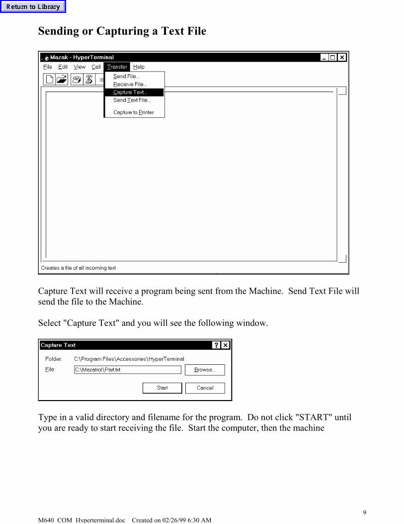
Sending or Capturing a Text File
Capture Text will receive a program being sent from the Machine. Send Text File willsend the file to the Machine.
Select "Capture Text" and you will see the following window.
Type in a valid directory and filename for the program. Do not click "START" untilyou are ready to start receiving the file. Start the computer, then the machine

M640 COM Hyperterminal.doc Created on 02/26/99 6:30 AM10
Sending a Text File
To send a text file click on "Transfer" and then "Send Text File" and you will see thefollowing window…….
When sending to the machine, type the name of the file to be sent in the box. Do notselect "Open". Go to the machine and select load first, and within a few seconds clickthe "Open" button.

M640 COM Hyperterminal.doc Created on 02/26/99 6:30 AM11
Cable Configurations
The proper cable configuration is needed to communicate with the machine throughWindows. Most problems with communications arise from the wrong cable, orincorrect parameter settings.
Communication Cable for 25pin to 25pin RS232
Computer MazatrolDB25 Female DB25 Male
2 33 27 745 56 68 820 20
Communication Cable for 9pin to 25pin RS232
Computer MazatrolDB9 Female DB25 Male
2 23 35 7
7 58 6
81 2046
To Top
M640 COM Hyperterminal.doc Created on 02/26/99 6:30 AM12
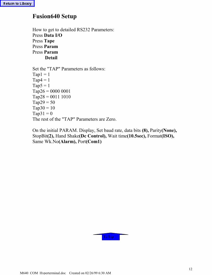
Fusion640 Setup
How to get to detailed RS232 Parameters:Press Data I/OPress TapePress ParamPress Param
Detail
Set the "TAP" Parameters as follows:Tap1 = 1Tap4 = 1Tap5 = 1Tap26 = 0000 0001Tap28 = 0011 1010Tap29 = 50Tap30 = 10Tap31 = 0The rest of the "TAP" Parameters are Zero.
On the initial PARAM. Display, Set baud rate, data bits (8), Parity(None),StopBit(2), Hand Shake(Dc Control), Wait time(10.5sec), Format(ISO),Same Wk.No(Alarm), Port(Com1)
To Top

M640 COM Hyperterminal.doc Created on 02/26/99 6:30 AM13
Mplus Com Parameters
Parameter CMT Tape DescriptionG1 2 2 BAUD RATEG2 3 3 STOP BITSG3 0 1 PARITY TYPEG4 0 0 PARITY CHECKG5 3 3 DATA BITSG6 1 1 TERM TYPEG7 0 0 TERM CODE1G8 0 0 TERM CODE2G9 0 1 CR LFG10 3 3 HAND SHAKEG11 1 1 DC CODEG12 0 0 DC CODEG13 3000 150 REPLY TIMERG14-16 0 0 RESERVED
PARAM VALUE PARAM VALUEG17 00000000 G35 0G18 0 G36 0G19 0 G37 0G20 0 G38 0G21 0 G39 00000000G22 0 G40 00000001G23 0 G41 0G24 0 G42 0G25 0 G43 0G26 0 G44 0G27 0 G45 0G28 0 G46 0G29 0 G47 0G30 0 G48 0G31 00000000 G49 00000000G32 0 G50 &45<E>G33 0 G51 &4E<N>G34 0 G52 &44<D>
To Top

M640 COM Hyperterminal.doc Created on 02/26/99 6:30 AM14
Tplus Com Parameters
Parameter CMT TAPE DescriptionI1 2 2 BAUD RATEI2 0 3 STOP BITSI3 0 0 PARITY TYPEI4 0 0 TERM CHECKI5 0 3 DATA BITSI6 0 3 HAND SHAKEI7 0 1 DC CODEI8 0 10 WAIT TIMER
Parameter ValueI9 0I10 1I11 1I24 0I49 &45(E)I50 &4E(N)I51 &44(d)
To Top

M640 COM Hyperterminal.doc Created on 02/26/99 6:30 AM15
Communications With Windows95
Troubleshooting
The machine gives an alarm (Tape reader miss connected)1. The cable is connected to the wrong port.2. Check the cable pinout.3. The cable length is too large or has some outside interference.
1. There is some problem in the cable. (Pins 2 & 3 are shorted?)The machine give an alarm (Set New Paper Tape)1. The timer is running out for reply wait time.2. If the program is an EIA/ISO transfer, check the end of the program. The control
looks for a (M02, M30, M99, and % to signal the end of the program.3. Check the parameter for the EIA/ISO end of program code.
The machine gives an alarm (H Parity Alarm)1. The cable is wired wrong.2. The wrong end of the cable is connected to the machine.3. The communications parameters are not set correctly.4. The serial port on the computer is using a high-speed sync mode. (Disable FIFO
buffers in the UART)5. The cable has interference caused by high voltage noise. (Welder, Lights, Wiring)
"I can download a program to the computer, but can not send it back to the machine.2. The control already has that program number registered. (Remove or renumber it)3. The timer for reply wait time is running out on the machine before the computer is
started.
To Top

M640_PrintKey_Instructions.doc 12/23/99 1:18 PM 1
M640_PrintKey_Instructions.doc
The following is quick explanation to use printkey.exe
This software will generate a hardcopy of screen and allow you to saveto a file without having a keyboard to do PrintScrn.
This software is freeware and can be distributed freely as long as nomoney exchanges hands.
To use, execute the printkey.exe. This will place the printkey icondown by date on taskbar. If you wish to make a hardcopy of screen, simplyclick with left mouse button. To view what you just made hardcopy of eithervery quickly click twice on left mouse or (preferable) press the right mousekey and select Open. When select Open you will see the screen saved. Click on the left floppy diskette to save to a file. Type in the filename and use either *.bmp or *.gif extension for saving. Bmp is best picture , but takes about 300 to 600k and vs about 7k to 14k for gif. So, you can put more Gif pictures on a diskette.
Note1: If you have a keyboard and press the PrintScrn key, the printkey software comes up.
Note2: You can use this software on your desktop pc if has Win95. Don't know about WinNT or Win98. This is useful for viewing saved files and printing and also for saving to clipboard to use in Word documents.
Note3: You can edit the area and save to clipboard using this software's tools.
Note4: If you click on right mouse and select Open, then the screen print will not show the Window's taskbar. Allowing you to show full Mazatrol menu keys.

M640_Printer_Information.doc 12/23/99 1:21 PM 1
M640_Printer_Information.doc
It is not possible to use the PRT02B or PRT02A printers that we have been using on the M640control. There is no Window's printer driver for them.
We can only use Window 95 supported printers and you will need to use a serial to parallelconverter.
The alternative is to add a PCMCIA ethernet card to the control and connect to a LAN systemand use a networked printer. This is probably the best way and how we have connected to ourlab.
We recently found that when connecting an HPLaserjet 5 which had a serial interface, it would print well on any screen but the program screen.
This was because the correct printer driver wasn’t installed. The Window’s 95 driver called up5MP and would get a bunch of lines. Installed one that came with printer for 5/5M(HPPCL5G.Drv) and worked perfectly. The serial cable was a null-modem cable purchased fromBest Buy.
I had same situation with an HP Laserjet 6 that was corrected when loaded the drivers whichcame with printer.
Another printer that our Champion Application got to work is the Panasonic KX-1520 and theyuse the Epson LQ 1000 printer driver.

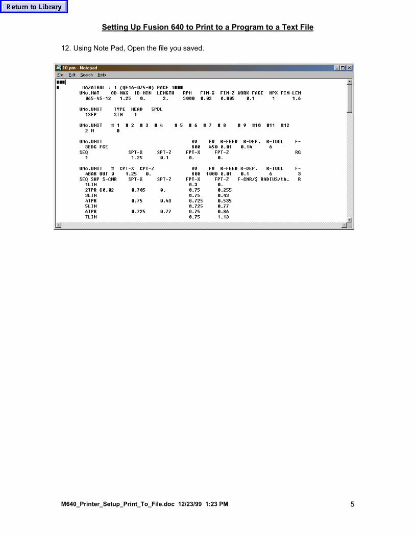
Setting Up Fusion 640 to Print to a Program to a Text File
M640_Printer_Setup_Print_To_File.doc 12/23/99 1:23 PM 1
M640 Printer Setup Print To File.doc
1. Move the cursor to the bottom left corner on the screen, left click once. The Start button
should appear. Click the start button, go to settings, then click on Printers.
2. Double Click Add Printer.
3. Click Next.
4. Select Local printer. Click Next.
5. Select Generic from the printer Manufacturers List. Click next.

Setting Up Fusion 640 to Print to a Program to a Text File
M640_Printer_Setup_Print_To_File.doc 12/23/99 1:23 PM 2
6. Select FILE: Creates a file on Disk. Click Next.
7. Check Yes. Click Next.

Setting Up Fusion 640 to Print to a Program to a Text File
M640_Printer_Setup_Print_To_File.doc 12/23/99 1:23 PM 3
8. Check No. Click Finish.

Setting Up Fusion 640 to Print to a Program to a Text File
M640_Printer_Setup_Print_To_File.doc 12/23/99 1:23 PM 4
9. Wait while the drivers load .
10. Test the printer driver by going to a program and selecting print from the File menu.
11. Click OK. Type the Name of the file you want to save the print as and select the location
where you want the file to be saved.
Setting Up Fusion 640 to Print to a Program to a Text File
M640_Printer_Setup_Print_To_File.doc 12/23/99 1:23 PM 5
12. Using Note Pad, Open the file you saved.

M640_MACRO_PRINT.DOC 12/23/99 1:26 PM 1
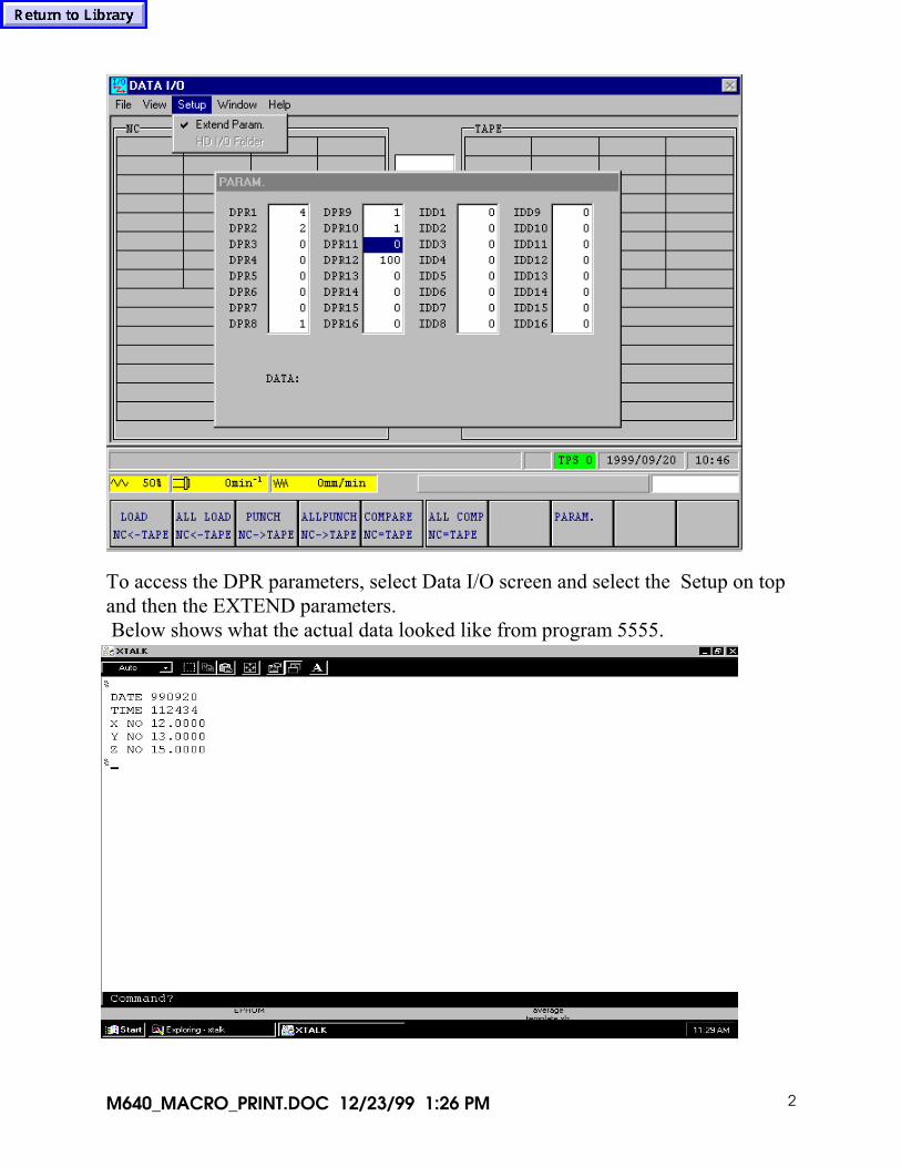
M640_Macro_Print.doc Below screens show program example and parameter settings for the CNCand tested connected to a computer running Xtalk.
Above shows a sample macro program. Set the other computer communicationparameters to 4800 baud, 2 stop bits, and evenparity. Used software handshaking, too. When print out to terminal screen, shows Time/Date and Wpc data.The communication parameters need to be set as shown below on the CNC. SetDPN parameters as shown. The internal Rs232 cable needs to be connected toCF22.(The leftmost Rs232 plug on operator pc board).
M640_MACRO_PRINT.DOC 12/23/99 1:26 PM 2
To access the DPR parameters, select Data I/O screen and select the Setup on topand then the EXTEND parameters. Below shows what the actual data looked like from program 5555.

M640_Ethernet_Network_Logon_Bypass.doc 08/09/99 11:29 AM 1
M640 Ethernet Network Logon Bypass.doc If you add an ethernet card and connect to a network, the controlwill automatically ask you for a password every time power on.This can become a nuisance and prevent machine from going intoauto-power on and running a warm-up program. It is possible to bypass this if you change the network settingto select “Windows logon” as shown below Next, go to Explorer and do a “Find files” to locate all files with theextension *.pwl These are the currently used password files and if theseare deleted Windows will ask you again for a username and passwordwhen you restart the control. At that point you have to enter a usernamebut do not even tab to the password block, just click on OK and it willnot ask for a password again..
When you add a card, it will assign Clien for Microsoft Networksas your primary logon. Change to say Window Logon and save.

M640 Ethernet Card Instruction
Note: The following was supplied from M640 projectteam and is good write up on installing an Ethernet card to theM640 control. However, please be aware that you should followthe instructions supplied with the ethernet card. Also, somenetworks may use IPX/SPX protocol instead of TCP/IP. Andtake special care when assigning the number for TCP/IP.
Technology explanation data
The introduction method of the network
The OutlineNecessary DevicesThe Connection of the DevicesThe Setting of SoftwareThe Sharing Method of Data
YAMAZAKI MAZAK Corp.Development & Design DivisionM640 Project team

1.The OutlineWe do such technical explanation that connects M640 to factory inside or inside a company premisesnetwork.You come to be able to forward machining program files, control of the “RUNNING CONTROL” dataon M640 and so on by connecting M640 to the network.Also, even to receive the network service of our company, when a modem is connected to the personalcomputer of the office that was connected the network becomes possible.On this sheet, we explain about the Ethernet 10BASE-T that is the most general network connectionmethod.If the network that you use is an Ethernet method, the outline is same almost. But only 10BASE-T isbeing supported, in the network devices that our company recommends for M640.
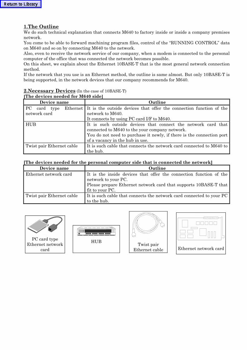
2.Necessary Devices (In the case of 10BASE-T)[The devices needed for M640 side]
Device name OutlinePC card type Ethernetnetwork card
It is the outside devices that offer the connection function of thenetwork to M640.It connects by using PC card I/F to M640.
HUB It is such outside devices that connect the network card thatconnected to M640 to the your company network.You do not need to purchase it newly, if there is the connection portof a vacancy in the hub in use.
Twist pair Ethernet cable It is such cable that connects the network card connected to M640 tothe hub.
[The devices needed for the personal computer side that is connected the network]Device name Outline
Ethernet network card It is the inside devices that offer the connection function of thenetwork to your PC.Please prepare Ethernet network card that supports 10BASE-T thatfit to your PC.
Twist pair Ethernet cable It is such cable that connects the network card connected to your PCto the hub.
Ethernet network cardTwist pair
Ethernet cable
HUBPC card typeEthernet network
card

3.The Connection of the Devices[The connection procedure on the side of M640](We explain it about EtherLink Ⅲ made of the 3Com company that our company is recommending)
[1]Preparation of connection1. Stop auto running operation and so on.2. Change running mode to Zero return mode and the screen to POSITION display.
[2]Connect Ethernet network card1. Please insert Ethernet network card into the optional slot in the PC card interface with 2 slots.2. When do for a while, the Hardware Wizard of Windows95 is triggered automatically and the
dialogue of the rough sketch is displayed.
[3]Install device driver1. Insert the device driver disk that is belonging to Ethernet network card into the floppy-disk
drive of M640.2. Click the “Next” button on above dialogue with mouse left button.3. The installation of the device driver begins. When do for a while, the following dialogue is
displayed.
4. Click the “Next” button on above dialogue with mouse left button.

5. The installation of the device driver is continued. When do for a while, the following dialogue isdisplayed.
6. Input “A:\” to “File of copy source” of above dialogue. And then, click “OK” button with mouseleft button.
7. The installation of the device driver is continued. When do for a while, the following dialoguewill be displayed.
8. Click “No” button on above dialogue with mouse left button for cancel to reboot Windows.9. Power off and power on the M640.
4.The Setting of Software[1]Power on after installation network
1.When power on M640 the following dialogue will be displayed after installed network.
2.When your click “OK” button with mouse left button, without inputting in a password anythingand input an optional user name, the triggering processing is continued. Normally, this dialogueis appeared each time when you power on. But you can also set up it so that you activate itwithout displaying this dialogue. If you want to set so, please see the following “[4] Changesetting “Enter Network Password” dialogue to be not appeared when power on”.
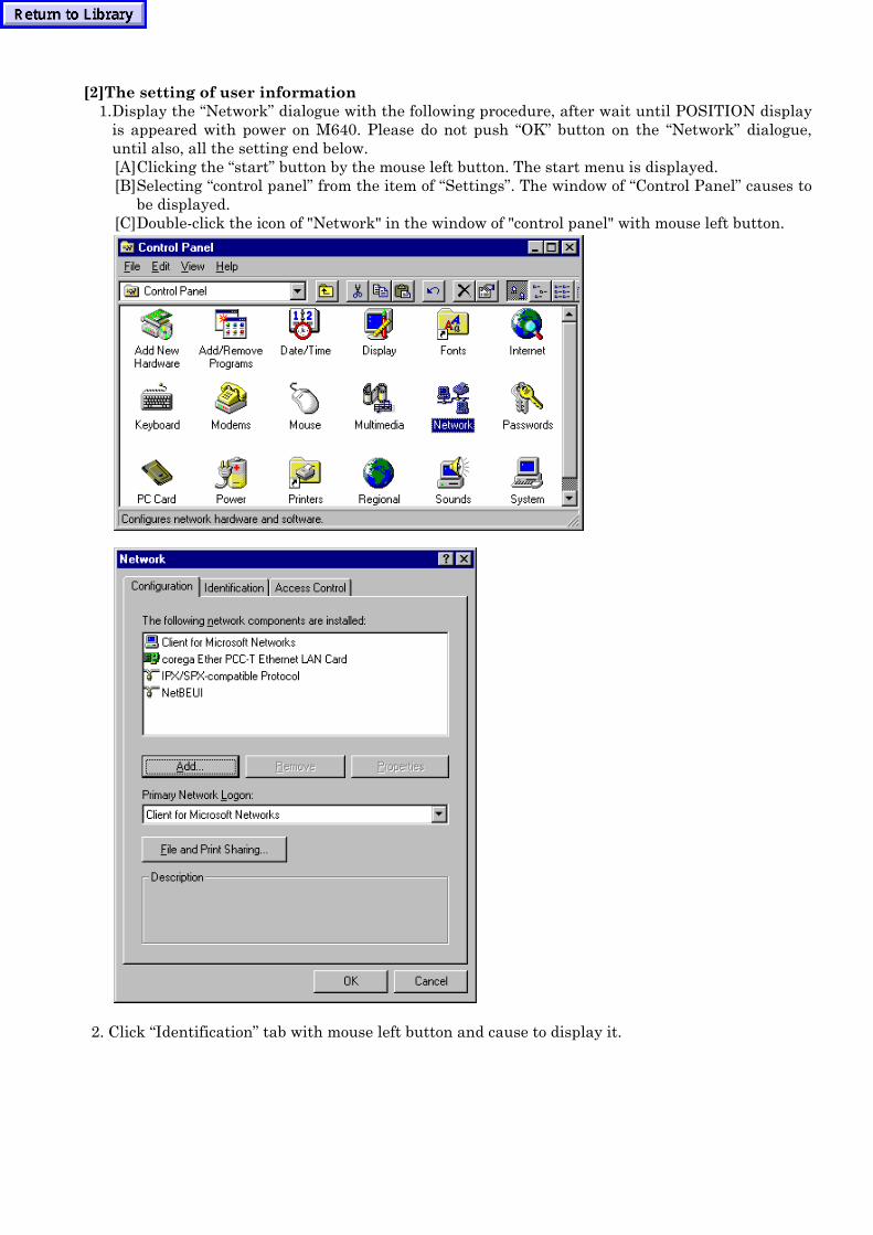
[2]The setting of user information1. Display the “Network” dialogue with the following procedure, after wait until POSITION display
is appeared with power on M640. Please do not push “OK” button on the “Network” dialogue,until also, all the setting end below.[A] Clicking the “start” button by the mouse left button. The start menu is displayed.[B] Selecting “control panel” from the item of “Settings”. The window of “Control Panel” causes to
be displayed.[C] Double-click the icon of "Network" in the window of "control panel" with mouse left button.
2. Click “Identification” tab with mouse left button and cause to display it.

2. Input the work group name and the computer name and then, push “OK” button. The computername becomes the name that network is distinguished. These names are an optional thing andbe good. However, the work group name shall be the same name as the personal computers of inaddition to that being connected to the network. (Ask the name that sets up it to the one, in thecase that the network manager is been.)
[3] Change the setting to be able to share data and printerIf you want to transfer program files with the other PC on the network or use printers connected toM640 from the other PC on the network, you have to do the following.1. Click “Configuration” tab with mouse left button and cause to display it.

2.Click “File and Print Sharing…” button with mouse left button, the sharing dialogue of the “Filesand Print Sharing” cause to be displayed.
3. Attach a check mark to “I want to be able to give others access to my files.”, in the case that youwant share the file of program etc with other personal computers.
4. Attach a check mark to “I want to be able to allow others to print to my printer(s).”, in case thatyou want use printers connected to M640 form other personal computers.
5. Close this dialogue by pushing “OK” button with mouse left button. When the sharing becomeseffective “File and Printer sharing for Microsoft Networks” is added to “The following networkcomponents are installed” of setting dialogue of the network.
[4] Change setting “Enter Network Password” dialogue to be not appeared when power onIf you do the following setting you can power on M640 without causing to display “Enter NetworkPassword” dialogue that usually, is displayed when power on.
1.Click “Configuration” tab with mouse left button.
2.Change “Primary Network Logon” to “Windows Logon” from “Client for Microsoft Networks”.

[5]The installation of TCP/IP protocol.If you do only want do control of the “RUNNING CONTROL” data, translate program etc, you donot need to install TCP/IP protocol.If your PC connected to network in your office has a modem, you can accept our company’s networkservices by installing TCP/IP protocol.
1. Click “Configuration” tab with mouse left button and cause to display it.
2. Click “Add…” button with mouse left button and cause to display “Select Network ComponentType” dialogue.
3. Click “Protocol” in “Select Network Component Type” dialogue and push “Add…” button.

4. Click “Microsoft” that is in the look of “Manufacturers” with mouse left button. And then, click“TCP/IP” that is in the look of “Network Protocols” with mouse left button.
5. Install TCP/IP protocol by pushing “OK” button. When the installation completes the TCP/IPprotocol is added to “The following network components are installed” of “Configuration” tab.
6. Click “TCP/IP” that is in the look of “The following network components are installed”. Andthen, push “Properties” button with mouse left button and cause to display “TCP/IPProperties” dialogue.
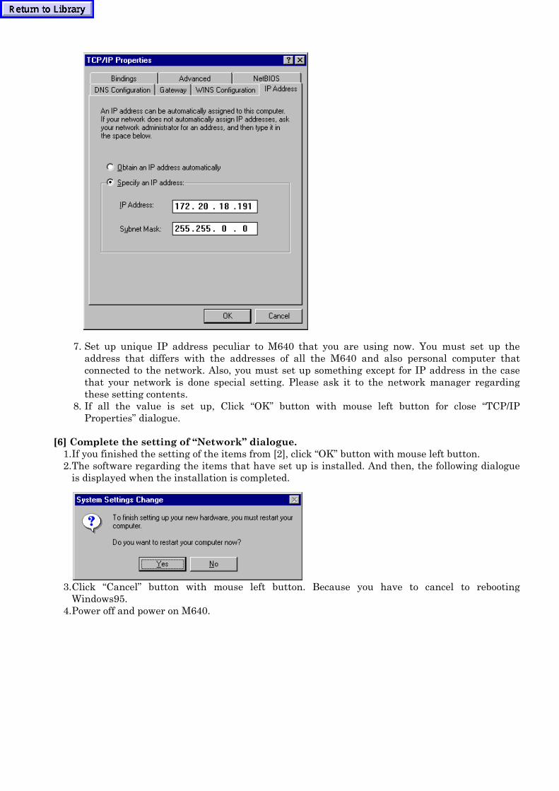
7. Set up unique IP address peculiar to M640 that you are using now. You must set up theaddress that differs with the addresses of all the M640 and also personal computer thatconnected to the network. Also, you must set up something except for IP address in the casethat your network is done special setting. Please ask it to the network manager regardingthese setting contents.
8. If all the value is set up, Click “OK” button with mouse left button for close “TCP/IPProperties” dialogue.
[6] Complete the setting of “Network” dialogue.1. If you finished the setting of the items from [2], click “OK” button with mouse left button.2. The software regarding the items that have set up is installed. And then, the following dialogue
is displayed when the installation is completed.
3. Click “Cancel” button with mouse left button. Because you have to cancel to rebootingWindows95.
4. Power off and power on M640.

5.The Sharing Method of DataFor example as the sharing method of data, forwarding of programs from PC connected to network toM640.We explain the forwarding programs from PC connected to network to M640.
[1] Change the Backup folder of M640 to a sharing folder1. Trigger Explorer and click the Backup folder with mouse right button.2. Click “Sharing…” item in the displayed menu with mouse left button.
3. Click “Shared As” radio button in the displayed dialogue with mouse left button.4. Click “Full” radio button listed in “Access Type” with mouse left button.
5. Push “OK” button.

6. Confirm that the Backup folder is turned sharing on Explorer. If the Backup folder is shared,you can see the mark of the hand is added to the icon of the Backup folder.
[2] Refer the shared Backup folder of M640 with your PC connected to network1. Trigger Explorer on the side of your PC connected to network. And then, confirm that there is
M640 in the list of PC on the network.2. Confirm that there is the Backup folder that is shared with the process [1] under M640 icon.

[3] Forward programs to the Backup folder that is shared to the network of M640 from PC1. Trigger two Explorer windows on your PC.2. Open the Backup folder of M640 on the network with one of Explorer.3. Double-clicking the “Programs” folder that is in the Backup folder with mouse left button to open
it.4. Open the folder that includes the forwarding program with Explorer of the other side.
Click and hold the forwarding program with mouse left button. And then drug & drop it tothe other window that displayed “Programs” holder on M640 and that opened by the otherExplorer.
[4] Move or copy the forwarding program to NC memory1. Display “PROGRAM FILE” display on M640.・ Move or copy the forwarding program to NC memory by using the program transfer function of“PROGRAM FILE” display. Please refer to “6-6 PROGRAM FILE Display” of OPERATINGMANUAL for M640.
M640_SW_regional_explanationB3a_and_C0.doc 12/23/99 1:42PM
1
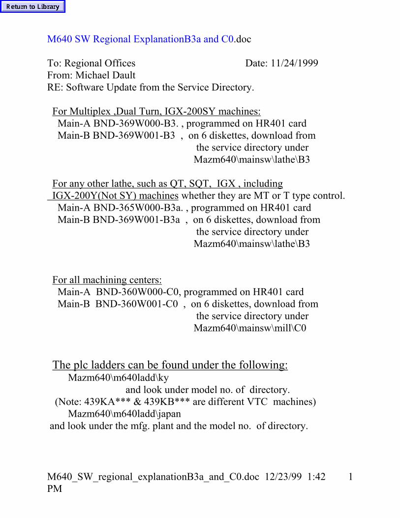
M640 SW Regional ExplanationB3a and C0.doc
To: Regional Offices Date: 11/24/1999From: Michael DaultRE: Software Update from the Service Directory.
For Multiplex ,Dual Turn, IGX-200SY machines: Main-A BND-369W000-B3. , programmed on HR401 card Main-B BND-369W001-B3 , on 6 diskettes, download from the service directory under Mazm640\mainsw\lathe\B3
For any other lathe, such as QT, SQT, IGX , including IGX-200Y(Not SY) machines whether they are MT or T type control. Main-A BND-365W000-B3a. , programmed on HR401 card Main-B BND-369W001-B3a , on 6 diskettes, download from the service directory under Mazm640\mainsw\lathe\B3
For all machining centers: Main-A BND-360W000-C0, programmed on HR401 card Main-B BND-360W001-C0 , on 6 diskettes, download from the service directory under Mazm640\mainsw\mill\C0
The plc ladders can be found under the following: Mazm640\m640ladd\ky and look under model no. of directory. (Note: 439KA*** & 439KB*** are different VTC machines) Mazm640\m640ladd\japan and look under the mfg. plant and the model no. of directory.

M640_Service_Drive_Directory.doc 12/23/99 1:44 PM 1
M640 Service Drive Directory.doc
Below shows the Service Drive Information under MazM640.Document -- All M640 Document procedures.M640ladd -- All M640 Ladders that I have. Broken into 3 main sources. 1) Japan A) Minokamo B) Oguchi C) Seiko 2) Ky These are from Ky. Production. 3) KySaleEngr These are from Ky. Sales Engr. Filed by Model Code and then version info.
Below show files within the 342KBT1.zip 1) qtn30m640plc.xls – Ladder front cover sheet
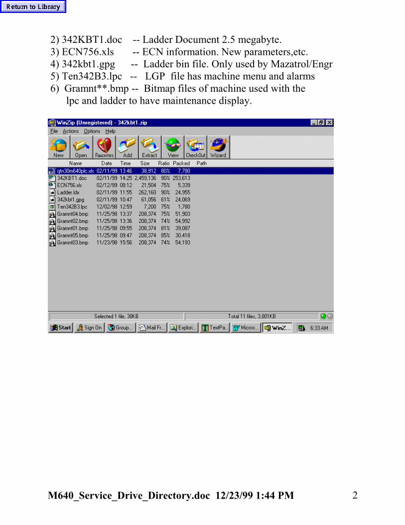
M640_Service_Drive_Directory.doc 12/23/99 1:44 PM 2
2) 342KBT1.doc -- Ladder Document 2.5 megabyte. 3) ECN756.xls -- ECN information. New parameters,etc. 4) 342kbt1.gpg -- Ladder bin file. Only used by Mazatrol/Engr 5) Ten342B3.lpc -- LGP file has machine menu and alarms 6) Gramnt**.bmp -- Bitmap files of machine used with the lpc and ladder to have maintenance display.

Mazatrol Fusion 640 (M) Version Form. Mach: S/N: TO ACCESS THE VERSION PAGE:A) PRESS DISPLAY SELECT BUTTON. B) PRESS DIAGNOS MENU BUTTON. C) PRESS VERSION. UNIT FCU6- SERIAL: MODEL: WINDOWS 95 PRODUCT ID:
ITEM VERSION ITEM VERSION MOTOR MACHINEMAIN-A SRV-X MAIN-B SRV-Y LG- SRV-Z LADDER SRV-4 LGP ENG SRV-5
SRV-6 SPN-1
J2CT-1 J2CT-2 J2CT-3 J2CT-4 J2CT-5 J2CT-6 J2CT-7
PRESS OPTION MENU BUTTON TO ACCESS OPTION PAGE. MARK THE OPTIONS WHICH ARE ACTIVE.
1 EIA 19 3-D CO-OR ROT. 37 SCALE F/B (A) 2 20 AUTO TLM 38 CYLINDER 3 SPIRAL 21 39 4 EIA 3D COMP. 22 COMPARISON STOP 40 5 ROTATION 23 HV CNTR. 41 NAVIGATION 6 GEOMETRIC 24 SYNC. CONT 42 IC CARD RUNNING 7 SCALING 25 EIA CONVERSION 43 EIA HELICAL TAP CYCLE 8 EXT-DATA I/O 26 SPLINE 44 MAZATROL HELICAL 9 MAZATROL 3D 27 G54.1 45 PROTOCOL B 10 28 SYNC.TAP 46 SHAPING 11 29 47 SUBMICRON SYSTEM 12 5-PLANE 30 48 NURBS INTERPORATION 13 HIGH SPEED 31 INCH/MM CONVERT 49 14 SHAPE COMP. 32 50 BORING TORNADO 15 THREAD 33 GOO SLOPE CONST. 51 MAZATROL PLANET TAP 16 34 SCALE FEEDBACK 52 17 INVERSE TIME 35 EIA CONVERSION 2 53 AUTO PECKING 18 DYNAMIC COMP 36 VARIABLE 600 SETSCUSTOMER NAME: DATE:
MACH. TYPE :

Mazatrol Fusion 640 (MT) Version Form. MACH: S/N: TO ACCESS THE VERSION PAGE:A: PRESS DISPLAY SELECT BUTTON. B: PRESS DIAGNOS MENU BUTTON. C: PRESS VERSION.
UNIT FCU6- SERIAL: MODEL: WINDOWS 95 PRODUCT ID:
ITEM VERSION ITEM VERSION MOTOR MACHINEMAIN-A SRV1-X MAIN-B SRV1-Z LG- SRV1-C LADDER SRV1-4 LGP ENG SRV1-5
SPN1-1 SPN1-2 SPN1-3
J2CT-1 SRV2-X J2CT-2 SRV2-Z J2CT-3 SRV2-CJ2CT-4 SRV2-4J2CT-5 SRV2-5J2CT-6 SPN2-1 J2CT-7 SPN2-2
PRESS OPTION MENU BUTTON TO ACCESS OPTION PAGE. MARK THE OPTIONS WHICH ARE ACTIVE. 1 BACKGROUND PATH CHECK 19 POLAR COORDINATES INPUT 2 EIA/ISO 20 CYLINDRICAL INTERPORATION 3 CHANGE TO EIA 21 POLYGON MACHINING 4 22 5 23 6 24 ENHANCED Y-AXIS MAZATROL 7 25 SYNCHRO. MAIN SPINDLE TAPPING 8 2ND AUXI FUNTIONS 26 EIA HELICAL INTERPOLATION 9 27 EIA COORDINATE ROTATION 10 Y-AXIS CONTROL 28 B AXIS CONTROL 11 SYNCHRO. MILL TAPPING 29 ENHANCED Y-AXIS MAZATROL(FACE1) 12 30 ENHANCED Y-AXIS MAZATROL(FACE2) 13 SCALE FEED BACK 31 EIA 1/100000 INCH DISP. 14 DIRECT DWG SIZE INPUT 32 GANTRY ROBOT CONTROL 15 USER MACRO 33 AUTO PECKING 16 600 MACRO VARIABLES 34 EIA HELICAL TAP 17 USER MACRO INTERRUPT 35 18 WORK COORDINATES SELECT 36CUSTOMER NAME: DATE:
MACH. TYPE:

Mazatrol Fusion 640 (T) Version Form. Mach: S/N: TO ACCESS THE VERSION PAGE:A: PRESS DISPLAY SELECT BUTTON. B: PRESS DIAGNOS MENU BUTTON. C: PRESS VERSION.
UNIT FCU6- SERIAL: MODEL: WINDOWS 95 PRODUCT ID:
ITEM VERSION ITEM VERSION MOTOR MACHINEMAIN-A SRV1-X MAIN-B SRV1-Z LG- SRV1-C LADDER SRV1-4 LGP ENG SRV1-5
SPN1-1 SPN1-2 SPN1-3
J2CT-1 SRV2-X J2CT-2 SRV2-Z J2CT-3 SRV2-CJ2CT-4 SRV2-4J2CT-5 SRV2-5J2CT-6 SPN2-1 J2CT-7 SPN2-2
PRESS OPTION MENU BUTTON TO ACCESS OPTION PAGE. MARK THE OPTIONS WHICH ARE ACTIVE. 1 BACKGROUND PATH CHECK 19 POLAR COORDINATES INPUT 2 EIA/ISO 20 CYLINDRICAL INTERPORATION 3 CHANGE TO EIA 21 POLYGON MACHINING 4 22 5 23 6 24 ENHANCED Y-AXIS MAZATROL 7 25 SYNCHRO. MAIN SPINDLE TAPPING 8 2ND AUXI FUNTIONS 26 EIA HELICAL INTERPOLATION 9 27 EIA COORDINATE ROTATION 10 Y-AXIS CONTROL 28 B AXIS CONTROL 11 SYNCHRO. MILL TAPPING 29 ENHANCED Y-AXIS MAZATROL(FACE1) 12 30 ENHANCED Y-AXIS MAZATROL(FACE2) 13 SCALE FEED BACK 31 EIA 1/100000 INCH DISP. 14 DIRECT DWG SIZE INPUT 32 GANTRY ROBOT CONTROL 15 USER MACRO 33 AUTO PECKING 16 600 MACRO VARIABLES 34 EIA HELICAL TAP 17 USER MACRO INTERRUPT 35 18 WORK COORDINATES SELECT 36CUSTOMER NAME: DATE:
MACH. TYPE:

MAZATROL FUSION 640 N.C. SOFTWARE CLAIM REPORTReporter : Report# Department : E-Mail Address : Date: Attached Data:
Customer : Machine Type: S/N: N.C. Type M640 M T MT TTESoftware NC Main A [ ] Ex: NC Main A [360W000-A0 ]Version NC Main B [ ] NC Main B [360W001-A0 ]
PLC Ladder [ ] PLC Ladder [40SW102-0500]LGP-ENG [ ] LGP-ENG [410W032-5 ]
Please send all data (Program, Tool Data, Parameter and etc…) via. E-MailMust Be E-Mail, with the data saved in DOS FILE FORMAT.Please note when you send the report without necessary file data, Japan will not investgate.Note: Please give the description with careful usage of IN, OUT, WHEN, IF should have and so on. When the problem can be illustrated or shown by numerical values, please provide all data. Such as GRAPHIC/POSITION/COMMAND DISPLAYS
1) Contents of problem: 2) Occurrence condition (Duplication Procedure): 3) Alternative method:
Questionnaire:1). Occurrence rate (%) ? Percentage Rate2) Method of problem duplication? Yes or No 3) Problem has been resolved by alternative programming/operating or explanation to the customer? Yes or No4) Software has to be corrected for the customer’s Yes or No5) Priority of the software Select From Drop Down List6) Other remarks or more
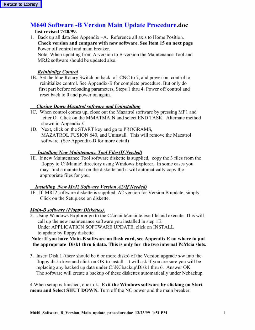
M640_Software_B_Version_Main_update_procedure.doc 12/23/99 1:51 PM 1
M640 Software -B Version Main Update Procedure.doc last revised 7/20/99.1. Back up all data See Appendix –A. Reference all axis to Home Position.
Check version and compare with new software. See Item 15 on next pagePower off control and main breaker.Note: When updating from A-version to B-version the Maintenance Tool andMRJ2 software should be updated also.
Reinitialize Control1B. Set the blue Rotary Switch on back of CNC to 7, and power on control to reinitialize control. See Appendix-B for complete procedure. But only do first part before reloading parameters, Steps 1 thru 4. Power off control and reset back to 0 and power on again.
Closing Down Mazatrol software and Uninstalling1C. When control comes up, close out the Mazatrol software by pressing MF1 and letter O. Click on the M64ATMAIN and select END TASK. Alternate method shown in Appendix-C1D. Next, click on the START key and go to PROGRAMS, MAZATROL FUSION 640, and Uninstall. This will remove the Mazatrol software. (See Appendix-D for more detail)
Installing New Maintenance Tool Files(If Needed)1E. If new Maintenance Tool software diskette is supplied, copy the 3 files from the floppy to C:\Mainte\ directory using Windows Explorer. In some cases you may find a mainte.bat on the diskette and it will automatically copy the appropriate files for you.
Installing New MrJ2 Software Version A2(If Needed)1F. If MRJ2 software diskette is supplied, A2 version for Version B update, simply Click on the Setup.exe on diskette.
Main-B software (Floppy Diskettes).2. Using Windows Explorer go to the C:\mainte\mainte.exe file and execute. This will call up the new maintenance software you installed in step 1E. Under APPLICATION SOFTWARE UPDATE, click on INSTALL to update by floppy diskette. Note: If you have Main-B software on flash card, see Appendix E on where to put the appropriate Disk1 thru 6 data. This is only for the two internal PcMcia slots.
3. Insert Disk 1 (there should be 6 or more disks) of the Version upgrade s/w into the floppy disk drive and click on OK to install. It will ask if you are sure you will be replacing any backed up data under C:\NCbackup\Disk1 thru 6. Answer OK. The software will create a backup of these diskettes automatically under Ncbackup.
4.When setup is finished, click ok. Exit the Windows software by clicking on Startmenu and Select SHUT DOWN. Turn off the NC power and the main breaker.

M640_Software_B_Version_Main_update_procedure.doc 12/23/99 1:51 PM 2
Main-A(HR401)5. Open the back cover of the NC unit and plug the Version upgrade ROM cassette (HR401) intothe CBUS2 slot located at the far most right end of the control.
6. Set the NC rotary switch (located on the bottom of the HR113 card) to “8”.
7. Turn on the main breaker and then turn on the CNC power.
8. The seven segment LED display (located next to the NC rotary switch) changes from “L” to“P” and finally to “Y”. This procedure is completed when display is “Y”. This should take abouttwo minutes.
9. Turn off the main breaker, (The CNC power-off button does not work.)
10. Reset the NC rotary switch back to “0” and pull out the ROM cassette. Power on machine and control.
11. Power on control and reload the PARAMETERS only.11a. Set any new parameters and save to Flash Ram using Maintenance Tools. When going from A to B on lathes, set O41 to 112. B265(Hd1 no. of chuck jaws) and B266(Hd2 or sub-spindle no. of chuck jaws) normally set to 3. P94 = 60 FOR (T) NC DATA TO HARD DRIVE Interval Save Time. L99 = 60 FOR (M) NC DATA TO HARD DRIVE Interval Save Time.
12. Go to “Diagnos” and select “Data Erase”. Select all items and select “Apply”. Type in –9999 and press Input.
13. Power off/on control. If have MrJ2 drives, may need to power off/on twice.
14. Reload the rest of the saved data(Tool data, Programs, Cutting Conditions, etc).
14a. Load in Navipara.txt data for lathes if update from A version. See M640_Navipara.doc
15. Check version page for correct version combination: For Quadrex,Mpx, DTurns, and Igx200sy will be : Main A 369W000-** Main B 369W001-*** For any other lathes including Igx200my will be: Main A 365W000-** Main B 369W001-*** For Any Machining center will be: Main A 360W000-** Main B 360W001-*** Note: Look at versions before starting update. Must be same 365/369 or 369/369combination. ** is version of HR401 for Main A , *** is version of Floppy Disks for Main B
Appendix - ASaving/Reloading parameter, cutting condition, maintenancedata to hard drive.

M640_Software_B_Version_Main_update_procedure.doc 12/23/99 1:51 PM 3
1) Select “Data IN/OUT”. 2) Press “HARD DISK”. 3) Select “DIR.SELECT” and type in directory. My suggestion is to use SAV1198 for datasaved in November of 1998. This directory can be found in the C:\T_BACKUP\Other\sav1198 on M640T. On M640M, it would be C:\M_BACKUP\Other\sav1198.
4) After directory is selected, press the “NC->HD SAVE” button.Select the files to be saved by bringing cursor down and hit INPUTkey which will highlight in blue.5) Press “START” and it will highlight and go out when saved.6) Confirm files are saved by pressing the “HD CONTENT” and “START”.
Note: If you Save Again in same directory, it will Erase the existing contentsfirst and then Save the new data. (Just like the Micro-Disk does)1) To reload data, simply do DIR. SELECT, select directory and press OK. Press “HD CONTENT” and “START”. Then “NC <- HD LOAD”, and “Start”.APPENDIX- B Reinitialize Control
1. Power off control.
2. Data should have been backed up by APPENDIX-A. Set blue rotary switch to “7”.
3. Power on control. The 7-segment LED above the switch will change as follows

M640_Software_B_Version_Main_update_procedure.doc 12/23/99 1:51 PM 4
very quickly 8-> 0-> 1 -> 2 -> 3 -> 4 -> 5 -> Y.
4. Power off control. Reset the rotary switch back to “0” position.
5. Power on control and reload the PARAMETERS only.
6. Go to “Diagnos” and select “Data Erase”. Select all items and select “Apply”. Type in –9999 and press Input.
7. Power off/on control. If have MrJ2 drives on this machine, power off/on twice.
8. Reload the rest of the saved data(Tool data, Programs, Cutting Conditions, etc).
Appendix C – Alternate way of Shutting Down Mazatrol Software1. Press the PARAM key and then the right end menu key. Type “1131” and press input to getinto the privileged mode.
2. Move the mouse pointer to the bottom edge of the message indication column. By pressing theright mouse button, a pull down menu will appear.
Bring the mouse pointer to this point
3. Select EXIT and press the right side mouse button.
Appendix D- Showing how to Uninstall Mazatrol Software

M640_Software_B_Version_Main_update_procedure.doc 12/23/99 1:51 PM 5
Click on Start, Programs, Mazatrol Fusion 640, and Uninstall.Make sure the Mazatrol Software is shut down(END TASK).
APPENDIX – EWith new Maintenance Tool it is possible to load the Main B software fromthe internal 2-slot PCMCIA slots. NOT FROM THE FRONT SLOT.

M640_Software_B_Version_Main_update_procedure.doc 12/23/99 1:51 PM 6
Below illustrates to activate IC Memory Card(PCMCIA).
[ Folder Location ]\verup\atsys\DISK1 \DISK2 \DISK3 \DISK4 \DISK5 \DISK6

M640_Software_B_Version_Main_update_procedure.doc 12/23/99 1:51 PM 7

M640_Re-initialization.doc 12/23/99 1:53 PM 1
M640 Re-Initialization Procedure.doc
1) Backup the programs, cutting conditions, tool data, maintenance, andparameter information. See M640_Data_Save_Procedure.doc for moredetail.
2) Zero return all axis and power off the control and machine.
3) A blue rotary switch is located beneath the CNC unit on the HR113 card.
4) Set that rotary switch from “0” to “7”.
5) Turn the NC power ON. The 7-segment LED located above the switch will change as shown below: 8 -> 0 -> 1 -> 2 -> 3 -> 4 -> 5 -> Y. This will happen extremely quickly.
6) Turn off the NC power.
7) Return the rotary switch back to “0” position.
8) Power on the control and reload the parameter information first.
9) Power control off/on.
10) Go to Diagnos, and press DATA ERASE. Click on everything to erase and press the Apply. Type in –9999 and press INPUT.
11) Go to Program, Program File, and select All Erase. Type in –9999 and press Input. This clears the program file area.
12) Reload the rest of the data.

M640_Data_Save_Procedure.doc 12/23/99 1:54 PM 1
M640 Data Save Procedure.doc
The following procedure shows how to save parameters to the FlashRom and/or hard drive for the Fusion controls. If an O-parameter is changed on the M640 control, you must save thechanged parameters to the Flash Rom located on the HR113 card. It issoldered on the card and not removable like the Plus series controls. A new feature is the capability to save the parameters, cuttingconditions, maintenance data to the control’s hard drive. This would beadvisable to do at machine installation time. See below for saving the parameters to Flash Rom.
Click on the upper blue part of screen and drag off to side. Click on the “MyComputer” icon once, and then click with right mouse key. Find the mainte.exe file on C:\mainte\ directory.

M640_Data_Save_Procedure.doc 12/23/99 1:54 PM 2
Select the BACKUPB.Click on the > symbol going to the FL-ROM. Display will ask you ifyou are Sure, select Yes.When done saving, it will say “Success”.Close all open Windows by clicking on the X in the upper right corner.Power off/on.
Saving parameter, cutting condition, maintenance data tohard drive.
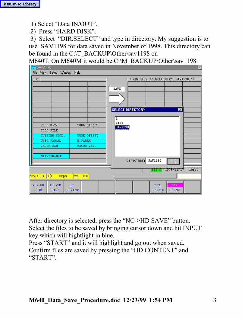
M640_Data_Save_Procedure.doc 12/23/99 1:54 PM 3
1) Select “Data IN/OUT”. 2) Press “HARD DISK”. 3) Select “DIR.SELECT” and type in directory. My suggestion is touse SAV1198 for data saved in November of 1998. This directory canbe found in the C:\T_BACKUP\Other\sav1198 onM640T. On M640M it would be C:\M_BACKUP\Other\sav1198.
After directory is selected, press the “NC->HD SAVE” button.Select the files to be saved by bringing cursor down and hit INPUTkey which will hightlight in blue.Press “START” and it will highlight and go out when saved.Confirm files are saved by pressing the “HD CONTENT” and“START”.

m640_parameter_servo_spindle_0_PitchError.doc 12/23/99 1:57 PM 1
M640 Parameter Servo Spindle O PitchError.doc
Locating Servo Parameters• Press parameter key• Right menu key• 1131 ENTER• Diagnose• Version• Servo Monitor• Param.• To change to Axis 4, 5, and 6 on M640M, select Param. again to Unhighlight the Param. and then Page forward arrow key. Thenselect Param. again to see Axis 4,5, and 6 parameters.
Locating Spindle Parameters
• Press parameter key• Right menu key• 1131 ENTER• Diagnose• Version• Spindle Monitor• Para.
Locating “O” and Pitch Error Parameters
• Press parameter key• Right menu key• 1131 ENTER• Diagnose• Version• Version (Right menu key labeled version)• Select System Param. for “O” parameters and Pitch Error accordingly.• Save to Flash Rom after Changing. Even though changes, will not be active till saved.
Note: Privilege mode only needs to enter once to perform all these procedures. If the1131 will not enter after selecting right menu key, you may already be in privilegemode.

M640_Servo_update_procedure.doc 12/23/99 1:59 PM 1
M640 Servo Update Procedure.doc
M640 SERVO/SPINDLE SOFTWARE
Tools needed:• M640 Servo/Spindle s/w download tools cassette (QX812)• M/T plus servo/spindle s/w cassette (QX81_)
1. Power down the control and the main breaker. Open control panel.
2. Set the NC rotary switch to “F”
3. Open plastic door to reveal CBus1 and CBus2.M640 Control
NC status LED NC rotary switch
4. The servo/spindle s/w cassette goes in the CBUS1 slot. The M640 s/wdownloader tool cassette goes in the CBUS2 slot.
Note: Presently on Mpx or Dturn systems with two heads, it is neccessary toupdate Hd1 servo’s first, and then power off andmove the serial bus cable from Hd1 servo to Hd2 servo’s andupdate Hd2 drive.

M640_Servo_update_procedure.doc 12/23/99 1:59 PM 2
5. Now set the rotary switches on the servo or spindle drives, depending onwhich s/w you are updating
• If you are updating the SERVO drives, add a value of 8 to theexisting setting on the rotary switch of the first servo in the line ofcommunications. The next servo drive should be set to the nexthigher value. If it is a dual servo drive the setting should be thesame for both rotary switches.
• If you are updating SPINDLE drive , you must change the rotaryswitch to “C”. If you have more than one spindle drive set theothers to “D”, “E”, etc. respectively. In other words, just add 1 tothe previous spindle drive download setting.
Note: The above apply to the smaller SVJ and SPJ’s, but they are adifferent version software. Don’t put SPJ software in a SP and vica-versa. Don’t mix SVJ in SV drives either.
EXAMPLE OF ROTARY SWITCH SETTINGS
1ST SERVO DRIVE DUAL SERVO DRIVE 3rd SERVO DRIVE SPINDLE DRIVE
CommunicationsLine (SH21 cable)
ORIGINALSETTING 0 1, 2 3 6
DOWNLOADSETTING 8 9, 9 B C
6. Turn on the main breaker and power up the control.
7. Watch the operation status on the NC seven-segment display. There will beno display on the LCD.
M640CNC/PC

M640_Servo_update_procedure.doc 12/23/99 1:59 PM 3
• The operation status is displayed as:STEP # CONTROL STATUS LED DISPLAY
1 ERASING E2 DOWNLOADING d3 PROGRAMMING P4 DOWNLOADING d5 PROGRAMMING P6 COMPARING C7 NORMAL FINISH
ABNORMAL FINISHY
E = error
8. Power down the control and remove the s/w cassettes. Return all rotaryswitches to their original positions.
9. Power up the control and verify, by looking at the version screen, the s/wversion did change to the new number.
10. Current Versions as of November 4, 1999SpindleMDS-B-SP BND-525W000 AE/ADMDS-B-SPJ BND-527W000 A6/A5MDS-B-SPH BND-525W002 B3/B2MDS-A-SP BND-520W000 AE/AD ,Plus onlyMDS-A-SPJ BND-522W000 A6/A5 ,Plus only
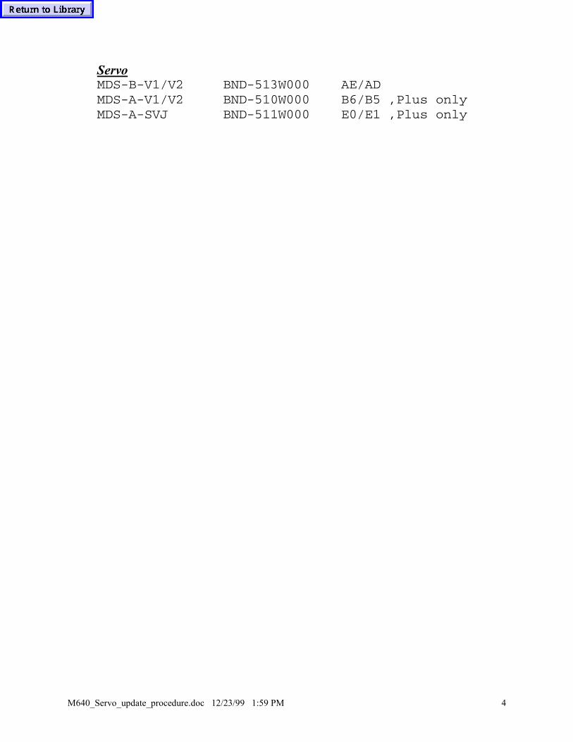
M640_Servo_update_procedure.doc 12/23/99 1:59 PM 4
ServoMDS-B-V1/V2 BND-513W000 AE/ADMDS-A-V1/V2 BND-510W000 B6/B5 ,Plus onlyMDS-A-SVJ BND-511W000 E0/E1 ,Plus only

M640_Maintenance_Display.doc 12/23/99 2:01 PM 1
M640 Maintenance Display.doc , rewritten 11/4/1999
MAINTENANCE CHECK PAGE DATA
The Maintenance Check data is stored on the Flash Ram area of the HR113card and is not accessible to be changed like the Plus series controls. In orderto change the data, you must first save the data to the hard drive, edit the savedfile, and then Read that file back to HR113 card.
Save Data to Hard Drive: A) Select DIAGNOS and then MAINTEN CHECK. B) At upper left corner, click on FILE and then FILE WRITE.
C) The data will now be saved into the hard drive under following directory(folder). M640M – C:\NM64MDATA\ENG\maintenance.txt M640T --- C:\NM64TDATA\ENG\maintenance.txt

M640_Maintenance_Display.doc 12/23/99 2:01 PM 2
D) Once data is saved, you can click on it in Windows Explorer as shown aboveand edit the file. When done making changes, save changes in NotePad by selectingSAVE and then Exit by clicking on the X marks in upper right of Notepad andExplorer. Note: IF THE "1500 AND 3000 HR" DATA MUST BE MODIFIED YOU MAY CURSOR DOWNUNTIL YOU FIND (MEI15) FOR 1500 HR CHECK LIST OR (MEI30) FOR THE 3000 HR LIST
Reading from Hard Drive to HR113 (CNC).
E) Go back to the NC mode’s maintenance page as shown previously and select FILE,then FILE READ. It will now reflect your changes.
Related Parameters: M640M- Third page of Maintenance page shown. F80 bit 3 to 1.

M640_plc_display_explanation.doc 12/23/99 2:05 PM 1
M640 PLC Display Explanation.doc
PLC Version Explanation for the M640 controlThe plc ladder and alarm message and menus are defined as shownbelow. Display the DIAGNOSE Screen to see version display.
PLC Ladder Title and Version On Display, you will see: LADDER 460W529-KA000 The 460W is a given. Numbers after 460W are broken down as follows:
First 3 digit: Model code of machine , in this case is 529. Last 5 digit: Actual version. Previous controls could only display 3 or 4 digits. 1st : Where manufactured. In this case “K” for Ky. 2nd : Standard Revision 0 – Z . 3rd, 4th : Option 00 – ZZ (2 digits if special, 00 if standard). 5th : Option Revision Level 0 – Z. The ladder itself is in the NC control. A backup copy may be on harddrive under c:\ Ladder\Ladder.Ldx
2) Alarm and Menu Title and Version Display On Display, will see: LGP-ENG 360W000-52900
360W000 is a given. First 3 digits: Model Code (529) Last 2 digits: Revision Level 00 – ZZ
Actual text file is on hard drive under c:\m6y_ymw\Tplc Filename in this example is MEN52900.LPC First 3 digit: M of MEN is for Machining Center T of TEN would be for Lathes. The EN indicates English. 4 – 6 digit : Model code, in this case 529. 7th,8th digit: Revision level , .LPC is extension.

M640_plc_display_explanation.doc 12/23/99 2:05 PM 2
Above shows a typical directory for a M640MT lathe. The BMP files are for the Graphic Maintenance. The Ten13500.lpc file is active. You see there are menu files in Danish(Tda13500.lpc),Japanese(Tjp13500.lpc),Polish(Tpo13500.lpc), and Swedish(Tsw13500.lpc). Inaddition is Ten13504.Sav which was renamed so that Ten13500.lpc would the active menu display file.

M640_ Plc_Corruption_Recovery.doc 12/23/99 2:08 PM 1
M640 PLC Corruption Recovery.doc
M640 PLC corruption recovery for M and T controls.
On Fusion 640 control, if you go to ladders and you get a Modal ID notregistered alarm, the plc has been corrupted. This is usually caused bytrying to load in a bad plc file that even Window’s Explorer can’t read.
1)Back up all data2)Re-initialize control
Power off, set rotary switch on hr113 board to 7, NC power on, wait for display to show Y then turn off main power. Do Not Load in parameter in till step 6!!!!
3)Turn on main power, set rotary switch to 1. (Stops plc).4)Turn on NC, on M640M set par K96 bit 5 to 1, NC off and on. on M640T set par O84 to 1, NC off and onYou should now be able to get into the ladder monitor to load the newladder
5)Turn off NC, you may need to shut down Windows manually. (To shutdown manually,Press MF1 and Letter 0 and select Shutdown.)6) Then power on and load parameters.7) Turn the NC off and on, reload the remaining tool data, etc.

M640_plc_saving_floppy.doc 12/23/99 2:09 PM 1
M640 PLC Saving Floppy.doc
Procedure to save the plc ladder to a floppy diskette
When installing a new machine, please have your serviceman save theladder(ladder.ldx file) and the accompanying *.lpcfiles.(See M640_plc_display_explanation.doc for filename explanation). To save the ladder and the menu files(*.lpc) do the following:
1) Insert the Blank formatted diskette into the Floppy Drive2) Press “Diagnos” menu key.3) Press “Version” menu key.4) Press “Ladder Monitor” menu key.5) Press “Tool” menu key.6) Press “Run/Stop” menu key.7) Select “Stop”8) Select “OK” PLC STOP is displayed, lower left.
9) Select “CLOSE”

M640_plc_saving_floppy.doc 12/23/99 2:09 PM 2
10) Select “NC -> HD to save to formatted floppy diskette. You must first “MAKE DIRECTORY”11) To make a directory, click on select. The upper select, and to the right of Destinate Directory
12) Double Click [-a-] drive, then select mkdir (Make Directory)13) Enter S/N of machine for the Directory Name. Select OK and Yes. (See Display Below)

M640_plc_saving_floppy.doc 12/23/99 2:09 PM 3
14. After making directory, double click on directory name, then click on Select

M640_plc_saving_floppy.doc 12/23/99 2:09 PM 4
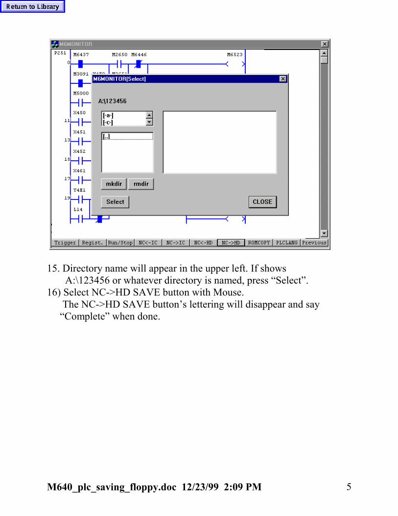
M640_plc_saving_floppy.doc 12/23/99 2:09 PM 5
15. Directory name will appear in the upper left. If shows A:\123456 or whatever directory is named, press “Select”.16) Select NC->HD SAVE button with Mouse. The NC->HD SAVE button’s lettering will disappear and say “Complete” when done.

M640_plc_saving_floppy.doc 12/23/99 2:09 PM 6
It will download the ladder.ldx(plc ladder) and some *.lpc files. The *.lpc files are the menu and alarm files and will probably be men**.lpc for English, mjp**.lpc for Japanese, mfr**.lpc for French. F.Y.I. these files are on hard drive under the c:\M6_ymw\Mplc for machining centers, c:\M6_ymw\Tplc.17) When says “Complete” its done, select the EXIT button.18) To get out of ladder monitor, press the “PREVIOUS” menu key.Then select “FILE” and “EXIT” menu buttons.

M640_plc_update_floppy.doc 12/23/99 2:12 PM 1
M640 PLC Update Floppy.doc
Procedure to update the PLC ladder files by Floppy Disk.
1) When update the plc to another machine, please have yourserviceman SAVE the existing ladder (ladder.ldx file) and theaccompanying *.lpc files, and *.bmp files
(See M640_plc_saving_floppy.doc for explanation).
Note: O84 bit 0 must be a 0 on M640T controls to allow load. K96 bit 5 must be a 0 on M640M controls to allow load.
It is possible to update by either IC Flash Memory Card orFloppy Diskette or Hard Drive.
The update will consist of 1 file with an .LDX extension.There may or may not be other file(s) with a .LPC extension.The *.LDX is the ladder, the *.LPC is the menu/alarm data.(See M640_plc_explanation.doc for more explanation)
2) RENAME the existing *.LPC files in c:\M6y_ymw\Mplc forM640M or c:\M6y_ymw\Tplc for M640T or M640MTTo do this, you must go into Windows Explorer.My suggestion for renaming would be same first part and changethe extension to *.sav
3) Now that everything is backed up, insert the floppy diskettewith the update on it. Go to Windows Explorer and create afolder with same version of plc you are updating in the c:\ladderfolder. For example, if you were sent files 342KBT1.ldx,342B3.lpc, and many *.bmp files, create 342KBT1 folder underit. The results will be as shown in figure 1. when done:

M640_plc_update_floppy.doc 12/23/99 2:12 PM 2
Figure 1.
You may not see a LADDER.LDX as shown in this example. Itcan be any name with the *.ldx extension. The provider of the ladder should give you this information:
The directory for this update is: A:\The filename for this update is: ladder.ldxThe above shows that you have the ladder.ldx file in theA:\ (root) folder chosen to do the update.
4) If included, copy the new *.lpc and *.bmp files into the C:\M6y_ymc\Tplc (lathe) or C:\M6y_ymw (machining center)
5) Go to the NC screens now, and Press “Diagnos” menu key.

M640_plc_update_floppy.doc 12/23/99 2:12 PM 3
6) Press “Version” menu key. 7) Press “Ladder Monitor” menu key. 8) Select “Tool” menu key. 9) Press “Run/Stop” and double-click the “STOP” button. 10) Click on “OK” and then on “CLOSE”. 11) Select “NC <- HD” menu key. 12) Press top “SELECT” to get correct directory. Using the example, it would be 342KBT1. 13) Select 342KBT1 and press “SELECT” when done. See figure 2.
figure 2.
14) Press the NC<- HD LOAD button and will see display changeslightly as seen on next page.While loading, the NC <- HD LOAD button fadens and whendone,

M640_plc_update_floppy.doc 12/23/99 2:12 PM 4
a dialog box will say Complete. This will take about 1 to 2minutes. If it asks you if you wish to overwrite some *.lpc files,just say Yes.
figure 3. It will upload the ladder.ldx(plc ladder) and any *.lpc files ifincluded in same directory on the card. The *.lpc files are themenu and alarm files and will probably be men**.lpc for English,mjp**.lpc for Japanese, mfr**.lpc for French. F.Y.I. these fileswill be saved to hard drive under c:\M6_ymw\Mplc for machiningcenters, c:\M6_ymw\Tplc. They are read on power up and loaded.The actual ladder is stored on the Flash Rom area of the HR113board of the CNC.15) When done, select the EXIT button.16) Get out of ladder monitor, press the “PREVIOUS” menu key.Then select “FILE” and “EXIT” menu buttons.17) Once out of ladders, power off control.18) Power on control, check version display for correct plc.

M640_plc_update_floppy.doc 12/23/99 2:12 PM 5

M640_Plc_LPC_File_Explanation.doc 12/23/99 2:15 PM 1
M640 PLC LPC File Explanation.doc
When a PLC is released from Ky. Production, there is an Ecn inExcel format, along with ladder.ldx, and optionally new bitmap and lpcfile. Japan engineering does not do this. Next page shows a typical Ecn release. Thisone if for QT30N PLC version 342KBT1 whereas thegraphic maintenance files were just added. If look at342KBT1.zip it contains these files:
NO. 756

M640_Plc_LPC_File_Explanation.doc 12/23/99 2:15 PM 2
MACHINE TYPE : QTN-30/30HP,QT-25L/35XS DATE : 2/11/99
START PERIOD : IMMEDIATELY FROM : ERIC CRUMP
1
CATEGORY [ X ] SOFTWARE [ ] PARTS
[ ] PARAMETER [ ] MANUAL
[ ] OTHER
RE : PLC UPDATE (342KBT0 TO 342KBT1)
1 The PLC for the Large QT's has been updated from 342KBT0 to 342KBT1. The
reasons for the update are as follows:
1) The spindle jog operation was modified. The spindle jog menu key has to
1 be pressed along with the MF1 key in order for the spindle to jog. When the two
buttons are released, the spindle is back to normal operation.
1
2) M-Codes were added to start and stop the chip conveyor.
1 a. M118 - The chip conveyor runs forward
b. M119 - The chip conveyor stops
3) Logic was added to allow the chip conveyor to be started and stopped by a
push button on the operator panel. R64 bit 7 has to be set to a 1 in order for the
push button to become active.
1 (NOTE: This modification to add a push button switch will only be made at
customer's request until Mitsubishi starts sending the sub-operating panel with
1 the push button already on.)
1 4) Logic was added so that the Auto Door will not manually open or close
unless the MF1 key is also held down.
1
5) The turret can now be operated manually in step mode or continuous.
1 a. R63 bit 2 has to be set to a 0 for the turret to operate in step mode.
b. R63 bit 2 has to be set to a 1 for the turret to operate in continuous mode.
1
6) Logic modified so that the Low Speed menu key for the inverter chip conveyor
is highlighted when the machine powers up.
Below shows the new lpc file: Ten342B2.lpc 1) First part is alarm 300 to 400 definition. 2) Second second is Menu definition. 3) Last part is the Graphic Maintenance file definition.;#Ten342B2.lpc

M640_Plc_LPC_File_Explanation.doc 12/23/99 2:15 PM 3
;#al_max 1632;#al_char 32;#al_use 50;#al_start[Alarm]350,1,OPERATING SWITCH FAULT351,1,SPINDLE CONTACTOR FAULT352,1,POWER SUPPLY CONTACTOR FAULT353,1,DOOR LOCK SWITCH FAULT354,1,AJC BODY REVERSE ALM355,1,LOCK PIN UP ALM356,1,LOCK PIN DOWN ALM357,1,SHIFT UP ALM358,1,SHIFT DOWN ALM359,1,AJC ORIENT ALM360,1,TIME OVER ALM361,1,LOCK PIN NOT UP SIDE362,1,LOCK PIN NOT DOWN SIDE363,1,BODY NOT FORWARD SIDE364,1,BODY NOT REVERSE SIDE365,1,SHIFT NOT UP SIDE366,1,SHIFT NOT DOWN SIDE367,1,DRUM NOT INDEX POSITION368,1,SPINDLE NOT STOP369,1,DRUM MOTOR THERMAL TRIP370,1,DRUM HAVE JAW371,1,TURRET SERVO ALARM372,1, AUTO DOOR INVALID POSITION373,1,DEPRESS AUTO DOOR OPEN PB374,1,DEPRESS AUTO DOOR CLOSE PB375,1,WAYLUBE LOW LEVEL ALARM376,1,CONVEYOR AUTO OVERLOAD SEQUENCE377,1,AL377378,1,CONVEYOR OVERLOAD "OFF"379,1,AL379380,1,AL380381,1,AL381382,1,AL382383,1,AL383384,1,AL384385,1,AL385386,1,AL386387,1,AL387388,1,AL388389,1,AL389390,1,AL390391,1,AL391392,1,AL392393,1,AL393394,1,AL394395,1,AL395396,1,AL396397,1,AL397398,1,AL398399,1,AL399;;#al_end;#op_max;#op_char 60;#op_use 36
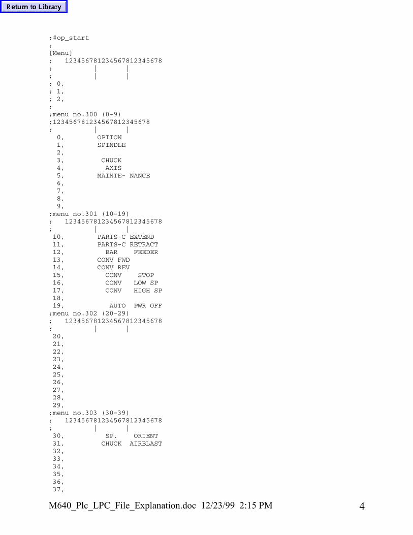
M640_Plc_LPC_File_Explanation.doc 12/23/99 2:15 PM 4
;#op_start;[Menu]; 123456781234567812345678; | |; | |; 0,; 1,; 2,;;menu no.300 (0-9);123456781234567812345678; | |
0, OPTION1, SPINDLE2,3, CHUCK4, AXIS5, MAINTE- NANCE6,7,8,9,
;menu no.301 (10-19); 123456781234567812345678; | |10, PARTS-C EXTEND11, PARTS-C RETRACT12, BAR FEEDER13, CONV FWD14, CONV REV15, CONV STOP16, CONV LOW SP17, CONV HIGH SP18,19, AUTO PWR OFF
;menu no.302 (20-29); 123456781234567812345678; | |20,21,22,23,24,25,26,27,28,29,
;menu no.303 (30-39); 123456781234567812345678; | |30, SP. ORIENT31, CHUCK AIRBLAST32,33,34,35,36,37,

M640_Plc_LPC_File_Explanation.doc 12/23/99 2:15 PM 5
38,39,
;menu no.304 (40-49); 123456781234567812345678; | |40,41,42,43,44,45,46,47,48,49,
;menu no.305 (50-59); 123456781234567812345678; | |50,51,52,53,54,55,56,57,58,59,
;menu no.306 (60-69); 123456781234567812345678; | |60,61,62,63,64,65,66,67,68,69,
;menu no.307 (70-79); 123456781234567812345678; | |70, EXT. CHUCK71, INT. CHUCK72,73,74,75,76,77,78,79,
;menu no.308 (80-89); 123456781234567812345678; | |80,81,82,

M640_Plc_LPC_File_Explanation.doc 12/23/99 2:15 PM 6
83,84,85,86,87,88,89,
;menu no.309 (90-99); 123456781234567812345678; | |90,91, TAILBODY UNCLAMP92,93,94,95,96,97,98,99,
;menu no.310 (100-109); 123456781234567812345678; | |100, COOLANT AUTO101, COOLANT MANUAL102,103,104,105,106,107,108,109,;menu no.311 (110-119); 123456781234567812345678; | |110,111,112,113,114,115,116,117,118,119,;; R8110[Mainte01]00,190,035,WORK LIGHT01,000,140,SPDL. POS. ENCODR.02,000,270,FOOT PEDAL SWITCH03,220,280,TOOLEYE EXT./RET.04,235,245,TOOLEYE SENSOR05,500,277,CMT PANEL06,360,260,LCD PANEL07,330,015,DOOR INTRLK.;R8111[Mainte02]00,210,300,Z-AXIS MOTOR

M640_Plc_LPC_File_Explanation.doc 12/23/99 2:15 PM 7
01,480,020,CHUCK CL/UCL SOL.02,355,290,SPINDLE MOTOR03,090,270,AIR SOLENOID;R8112[Mainte03]00,040,237,LUBE TANK MOTOR01,000,087,LUBE PRESS. SW.02,300,030,TURRET ASSEMBLY03,140,270,LUBE FLOAT SW.04,365,275,HYDRAULIC MOTOR05,500,223,PRESSURE SW.06,190,300,TRANSFORMER;R8113[Mainte04]00,250,010,TURRET HYDRAULIC MOTOR01,450,100,CLAMP PROX. SWITCH02,160,030,X-AXIS MOTOR03,120,290,X-AXIS ZERO POSITION04,440,042,TURRET CL/UCL SOL.05,440,187,TURRET FWD/REV SOL.;R8114[Mainte05]00,450,240,TAIL SLEEVE FWD/REV PROX.01,100,050,TAIL SLEEVE02,475,118,TAIL BODY MOTOR03,270,030,TAIL BODY FWD. SW.04,070,255,TAIL BODY CL/UCL SOL.05,450,050,TAIL SLEEVE FWD/REV SOL.06,415,000,TAIL SLEEVE PRESSURE;R8115[Mainte06];R8116[Mainte07];R8117[Mainte08]
Lastly, the bitmap files are included and are numberedGramnt01.bmp thru Gramnt05.bmp

M640_Plc_LPC_File_Explanation.doc 12/23/99 2:15 PM 8
This is the first Graphic maintenance file. Gramnt01.bmp
This is 2nd graphic maintenance file. Gramnt02.bmp

M640_floppy_installation_instruction.doc 12/23/99 2:18 PM 1
M640 Floppy Installation Instruction.doc
The cable should be attached to the floppy side already. If thiscable is not connected, refer to this picture for cable placement.
The other end of the floppy cable is labeled CFD. This cable isplaced in the slot marked CFD on the rear control panel. Thehighlighted area represents the CFD slot.• Power off control• Plug CFD connector into CFD slot• Power on control
IF floppy does not respond, check floppy LED.If this is on and nodisk is in floppy, check ribbon cable connection. (Possible thatcable is plugged in backwards.)

M640_Hard_Disk_Replacement_Procedure_B2version.doc 12/23/99 2:21 PM 1
M640 Hard Disk Replacement Procedure.doc updated 10/29/1999 adding newB-version files for alarm navigation and lathe navigation files.
1. Backup saved data following the M640_Data_Save_ Procedure. (This is done as a precaution just in case some datais lost.) If this is to replace a damaged drive. See Appendix A and B. You canrecover customer’s program by going to directories listed below.
2. Backup the following data, using Windows explorer, to a floppy disk or to an IC memory card connected to one ofthe two PCMCIA slots located on the back of the control. (You cannot use the front IC memory card slot.) Youmay either “drag and drop” or “cut and paste” each file from the hard drive to your target device.
Below chart show the data and how directory(s) look when in Dos mode(Dos view).
DATA TYPE FOLDER PATH NAME
Machining programs-Lathe -M/C
C:\T_Machine programs (C:\T_MACH~1,dosview)
C:\MC_Machine Programs (C:\MC_MAC~1,dosview)
Programs backed up on hard drive-Lathe
M/C
C:\T_Backup (C:\T_BACKUP,dos view)C:\MC_Backup (C:\MC_BAC~1,dos view)
Programs for HDD running -Lathe -M/C
C:\T_Direct mode programs (C:\T_DIRE~1, dosview)
C:\MC_Direct mode programs(C:\MC_DIR~1, dosview)
Sampling data – Lathe - M/C
C:\T_sdg and all sub-directoriesC:\MC_sdg and all sub-directories
MR-J2-CT parameter dataC:\J2ctbus\*.prm
Note: This is only backup data. Actual parametersare stored in the MR-J2 drive.
Menu files(*.Lpc,*.bmp,*.alm) –Lathe
- M/C
C:\m6y_ymw\Tplc C:\m6y_ymw\Mplc
PLC macros on some lathes C:\T_PLC program( C:\T_PLCP~1, dos view)
Navigation files on lathe if B-version C:\\nm64tdata\navipara.txt
System macros on some lathes C:\T_System macros( C:\T_SYST~1, dos view)
3. Back up the above programs and data. Depending on the Machine/option configuration, some items may not berequired. If hard drive information is unrecoverable, then request the Menu LGP files from your regional office.If power on without these files, machine menus will be missing. However,check ladder version and inform your office of what ladder and they can sendthe appropiate version.
4. Power down control. Turn off main breaker.5. Replace the hard drive. Take special care to make sure cable is plugged in
correctly. Place hand on cable where plugged into hard drive when power on.If gets real hot if plugged in wrong. Should see “Starting Win95” within 10 to 15 seconds, if not, power off andrecheck cable.
6. Turn on the main breaker and the NC power.

M640_Hard_Disk_Replacement_Procedure_B2version.doc 12/23/99 2:21 PM 2
7. Using Windows explorer, reload the backed up (in step 2) data. Power off/on.
Appendix AWe have had some Hard Drive failures on Fusion controls. The mostreported failure is that customer would power off at night and restartmachine in the morning. At that point, the control will come up withthe following alert: The following file is missing or corrupted c:\windows\mimem.sys Windows expanded memory driver Version 4.95 Copyright 1988-1995 Microsoft Corp.
EMM386 Not Installed - XMS Manager Not Present
C:\
If this happens, replace the hard drive, in dos mode you can save the information shown above so can input on new hard drive. Most important is the *.lpc, *.bmp, and *.alm file in C:\m6y_ymw\tplc or mplc area. If have a lathe with B-version or greater, there may be a navipara.txt in C:\nm64tdata If this happens, please order a replacement hard drive. You will need the OEM number which is on the Certificate of Authenticity. Also, what is version on machine. You will have to go by past records, most importantly is machine control type and machine. And fill out Appendix B sheet.

M640_Hard_Disk_Replacement_Procedure_B2version.doc 12/23/99 2:21 PM 3
Appendix-BFill out this form when replacing drive and send back with failed drive:
MAZATROL FUSION 640HARD DRIVE UPDATEREPLACEMENT REPORT
*THIS DATA IS REQUIRED TO PROPERLY TRACK **HARD DRIVE UPDATES IN THE FIELD *
Customer name:Customer address:
Contact name:NC serial # :NC control unit type: MU514 / MU515 / MU515-12Windows product ID # :New hard drive serial number:Old hard drive serial number:Main A s/w version:Main B s/w version:Cabinet # :Machine serial # :Machine type:Installation date:U.S. made machine: Y / N
Your name: Date:
Region: Phone #:
* BOTH MAZAK AND MITSUBISHI NEED THIS ** INFORMATION FOR EACH *

M640_Hard_Disk_Replacement_Procedure_B2version.doc 12/23/99 2:21 PM 4
* HARD DRIVE REPLACEMENT *PLEASE RETURN THIS DOCUMENT WITH THE OLD HARD DRIVE
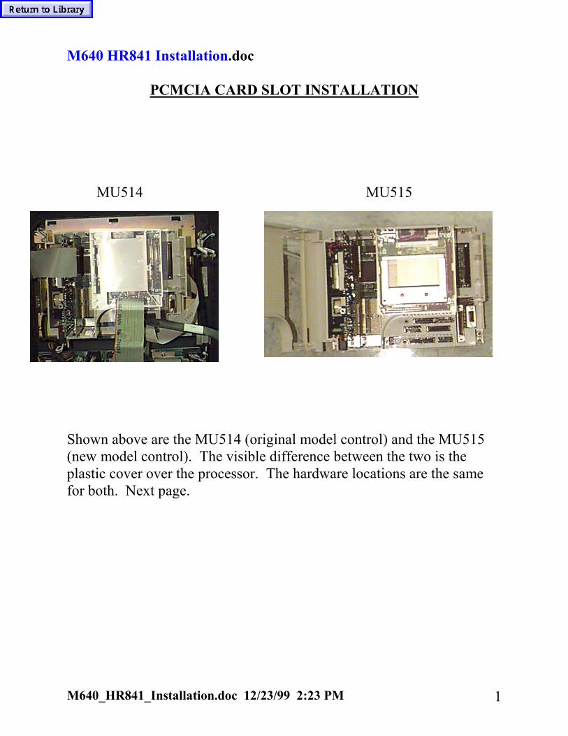
M640_HR841_Installation.doc 12/23/99 2:23 PM 1
M640 HR841 Installation.doc
PCMCIA CARD SLOT INSTALLATION
MU514 MU515
Shown above are the MU514 (original model control) and the MU515(new model control). The visible difference between the two is theplastic cover over the processor. The hardware locations are the samefor both. Next page.

M640_HR841_Installation.doc 12/23/99 2:23 PM 2
To install the PCMCIA slot card simply:1) Power down the control2) Connect ribbon cable to the right of plastic cover on the
MU514 or the processor on the MU515. (MU514 shown)
Once you have made the connection between the control and thecard slot PCB via ribbon cable, simply snap the PCB into the plastichousing as shown above.
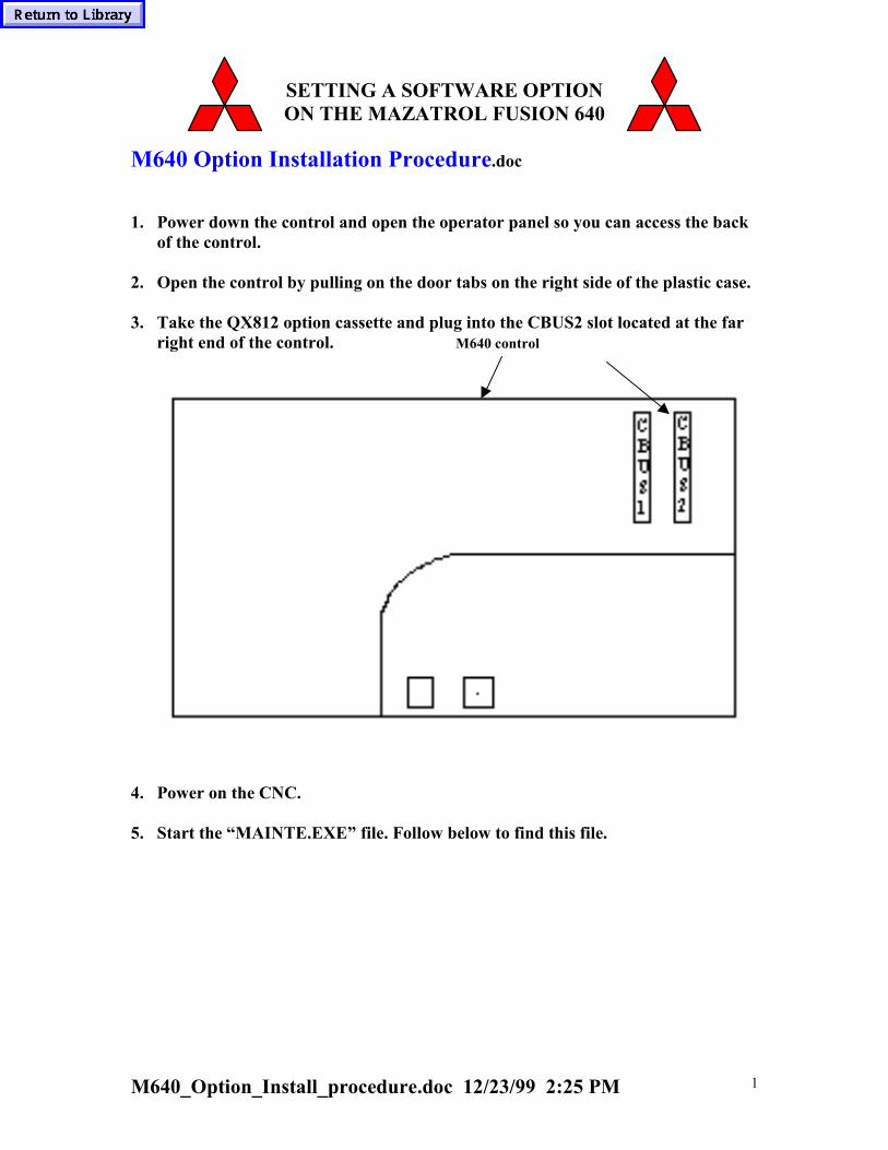
M640_Option_Install_procedure.doc 12/23/99 2:25 PM 1
SETTING A SOFTWARE OPTIONON THE MAZATROL FUSION 640
M640 Option Installation Procedure.doc
1. Power down the control and open the operator panel so you can access the backof the control.
2. Open the control by pulling on the door tabs on the right side of the plastic case.
3. Take the QX812 option cassette and plug into the CBUS2 slot located at the farright end of the control. M640 control
4. Power on the CNC.
5. Start the “MAINTE.EXE” file. Follow below to find this file.

M640_Option_Install_procedure.doc 12/23/99 2:25 PM 2
• Click on the blue top of the position screen and move it to theright as shown below. Double click on “My Computer”.
• Double click on “C” hard drive and look for the “mainte” folder.

M640_Option_Install_procedure.doc 12/23/99 2:25 PM 3
• Double click this folder and double click on the “mainte.exe” file.
6. Select “option menu”
7. Select “Installation”. Wait for the “Option loaded with success” window, click“ok”, then select “Exit”
8. Power off then on���� option becomes effective. Set any option parameters ifnecessary.

M640_Option_Install_procedure.doc 12/23/99 2:25 PM 4
9. Confirm option installation by verifying the particular option is highlighted inblack on the option page.
M640_SanDisk_Explanation.doc 12/23/99 2:26 PM 1
M640 SanDisk Explanation.doc
The M640 front slot uses Memory Cards for uploadingand downloading data. Mitsubishi is being very insistenton what type of cards to use. If customer is wanting to runfrom the IC card, the CNC option “IC Memory Card Running” must bepurchased from Mitsubishi. Mazak sales calls this optionIC Memory Card Operation. IC Memory Card Interface is standard andallows you to upload/download data to IC card. IC Memory CardOperation option is only available for theM640M(machining center) control. Not available for M640T orM640MT, or M640TE. This option is around $4500. Also, Mitsubishi insists on what type of Ethernet card for the 2-slotPCMCIA rack. See below. This information was in the manuals whenwe had the preliminary M640 class this June. Seepage 22 of BNP-B3699-158C. The lan card is EtherLink III3C589D.
I sent the following message by Email on 11/2/98.When using the San Disk Memory Cards. Mitsubishi states must usethe "Type 2 ATA standard 5 volt type". Any other types is not acceptable. Any other type must beapproved in writing by Mitsubishi.Also, please note that they only recommend one type of Ethernetcard and mfr. Etherlink III 3C589D manufactured by 3COM.
As of March, 1999, with new HR251 we can now use a flash typeSan Disk which is about 3.3 volt. Older version is a HR251B version. Older cards can be upgraded ata cost of about 150 dollars.

M640_Option_Overload_Detect.doc 12/23/99 2:28 PM 1
M640 Option Overload Detect
The M640T and MT has the overload detect feature thesame as Tplus control. 1) However, there are some differences in the setting of the O-parameter. Set O61 to AscII value, not hex. For example, if using A as the Misc. code, input 41 for O61 (Not 65 like on Tplus). If using “B” as the Misc. code, input 42 for O61. Note: If there is a B-code already used on machine like SQT or Igx200 always use “A” setting.
2.) Set R53 bit 4. Verify this is correct R-parameters, but this has been used universally on all lathes so far.
3.) Save these parameters to the Flash Rom. You must save to Flash Rom area to become effective.
4.) Below is a sample program used on Igx200sy.

M640_Option_Overload_Detect.doc 12/23/99 2:28 PM 2
The following is an explanation of program. See manual number 712S064, Op. Manual for Overload Detector for more detail. M378 100 is Peak Value of current. Set at 100 percent usually. M376 90 Overload Detect amount M377 10 Overload Detect dwell amount M379 1 Data is entered into Table 1. M371 201 Z-axis check Table 1 value M374 When overload detected, NC feedhold on. Spindle and Mill spindle not stopped.
An easy test is to put a piece of wood between chuck and turret and run at low feedrate. It should alarm out on Z axis slightly over 90% load. Below illustrates the ladder handling of this option.
R81 is actual load D501 is M376(But was changed to 100 at time this ladder was checked. T187 and D511 is M377 value of 10(1 second). D551 is M378 value of 100.

M640_Data_Save_Sram_Procedure.doc 12/23/99 2:30 PM 1
M640 Data Save SRAM Procedure.doc
To capture Data to SRAM: 1) Go to Explorer and find the M6YBoot folder. 2) Find TrsData2.exe and double click on to execute. 3) Press START button and it will write the data onto floppy diskette under filename Sramdt01.asc. 4) Send us the file along with bit maps or Jpeg image of the Tool Data page, Position(Command) screen, and any other important pages. Please remember the the bit maps are about 300k so can only get 3 to 4 per floppy diskette.

M640_Data_Save_BUSCON.doc 12/23/99 2:31 PM 1
M640 Data Save BUSCON.doc
The following is explanation on using the Buscon softwareon Control to save data for a problem where control will hangup in acycle start mode. 1) Power off control and plug in an external keyboard on back of theoperator control panel. On Dual Turn/Mpx op. panels, the port is locatedabove the hard drive. On other machine types, just below the hard drive.Note: Uses IBM PS/2 connector.
2) Start up the Printkey software. See Appendix A for Printkey software instructions.
3) Using Windows Explorer, select Buscon.exe in the C:\m6yboot directory.

M640_Data_Save_BUSCON.doc 12/23/99 2:31 PM 2
4) Select F4 and select S(for Small char). At this point, minimize the Buscon software. Click on CNC side’s title bar to turn it blue and run program.

M640_Data_Save_BUSCON.doc 12/23/99 2:31 PM 3
At this point, wait for problem of cycle hangupto reoccur, before going to next step
When problem occurs, maximize the BusCon and5) Type in the letter i (Small i ) Will default to small i due to previous step 4 where had selected S for small.6) Do a Printkey of data displayed. One of the data will say Busy or something. That should tell Japan something. Reason for External Keyboard is that machine keyboard is probably locked up when problem occurs. If press PrintScreen key on external keyboard, will call up the Printkey software. 7) Do a printkey of Key History page. This will show keys pressed before problem occurred. e.g. Operator changed offset?, etc. 8) Next, do a PrintKey of the Position page and Alarm History. 9) Save all data to a floppy diskette and to SRAM(see M640_ Data_Save_Sram_Procedure).

M640_Data_Save_BUSCON.doc 12/23/99 2:31 PM 4
Appendix A (How to use PrintKey software)
The following is quick explanation to use printkey.exe
This software will generate a hardcopy of screen and allow you to saveto a file without having a keyboard to do PrintScrn.
This software is freeware and can be distributed freely as long as nomoney exchanges hands.
To use, execute the printkey.exe. This will place the printkey icondown by date on taskbar. If you wish to make a hardcopy of screen, simplyclick with left mouse button. To view what you just made hardcopy of eithervery quickly click twice on left mouse or (preferable) press the right mousekey and select Open. When select Open you will see the screen saved. Click on the left floppy diskette to save to a file. Type in the filename and use either *.bmp or *.gif extension for saving. Bmp is best picture , but takes about 300 to 600k and vs about 7k to 14k for gif. So, you can put more Gif pictures on a diskette.
Note1: If you have a keyboard and press the PrintScrn key, the printkey software comes up. Note2: You can use this software on your desktop pc if has Win95. Don't know about WinNT or Win98. This is useful for viewing saved files and printing and also for saving to clipboard to use in Word documents. Note3: You can edit the area and save to clipboard using this software's tools. Note4: If you click on right mouse and select Open, then the screen print will not show the Window's taskbar. Allowing you to show full Mazatrol menu keys.

M640_Class_Index_Alphabetically_November99.doc 12/23/99 2:33 PM 1
INDEXM640_Class_Index_Alphabetically_November99.doc
The following is an index of the M640 Procedures in alphabetical order:
Document Title PageM640_Com 1M640_Com_Hyperterminal 10M640_Data_Save_Procedure 65M640_Data_Save_Buscon 109M640_Data_Save_Sram_Procedure 108M640_Data_Xfer_3Digit_For_M640T 2M640_Data_Xfer_3Digit_For_M640M 6M640_Ethernet_Card_Instruction 34M640_Ethernet_Network_Logon_Bypass 33M640_Floppy_Installation 94M640_Hard_Disk_Replacement 95M640_HR841_Installation(PcMcia card reader) 98M640_Macro_Print 31M640_Maintenance_Display 71M640_NC_Claim_Report 56M640_Option_Installation_Procedure 100M640_Option_Overload_Detect 106M640_Parameter_Servo_Spindle_O_PitchError 66M640_Plc_Display_Explanation 73M640_Plc_Corruption_Recovery 75M640_Plc_Saving_Floppy 76M640_Plc_Update_Floppy 82M640_Plc_Lpc_File_Explanation 86M640_Printkey_Instructions 24AM640_Printer_Information 25M640_Printer_Setup_Print_To_File 26M640_Re-Initialization 64M640_SanDisk_Explanation 104M640_Service_Drive_Directory 48M640_Servo_Update_Procedure 67M640_Software_B_Version_Main_Update_Procedure 57M640_SW_Regional_ExplanationB3 47M640_Version(M) 53M640_Version (MT) 54M640_Version(T) 55