matrix 3200/6400 audio switcher user's manual - extron electronics
TRANSCRIPT

Matrix 3200 and 6400 SeriesAudio Switcher
68-355-07 Rev. APrinted in the USA
This symbol is intended to alert the user of important operating and maintenance(servicing) instructions in the literature provided with the equipment.
This symbol is intended to alert the user of the presence of uninsulated dangerousvoltage within the product's enclosure that may present a risk of electric shock.
CautionRead Instructions • Read and understand all safety and operating instructions before using the
equipment.
Retain Instructions • The safety instructions should be kept for future reference.
Follow Warnings • Follow all warnings and instructions marked on the equipment or in the userinformation.
Avoid Attachments • Do not use tools or attachments that are not recommended by the equipmentmanufacturer because they may be hazardous.
WarningPower sources • This equipment should be operated only from the power source indicated on the
product. This equipment is intended to be used with a main power system with a grounded(neutral) conductor. The third (grounding) pin is a safety feature, do not attempt to bypass ordisable it.
Power disconnection • To remove power from the equipment safely, remove all power cords fromthe rear of the equipment, or the desktop power module (if detachable), or from the powersource receptacle (wall plug).
Power cord protection • Power cords should be routed so that they are not likely to be stepped on orpinched by items placed upon or against them.
Servicing • Refer all servicing to qualified service personnel. There are no user-serviceable partsinside. To prevent the risk of shock, do not attempt to service this equipment yourself becauseopening or removing covers may expose you to dangerous voltage or other hazards.
Slots and openings • If the equipment has slots or holes in the enclosure, these are provided toprevent overheating of sensitive components inside. These openings must never be blocked byother objects.
Lithium battery • There is a danger of explosion if battery is incorrectly replaced. Replace it onlywith the same or equivalent type recommended by the manufacturer. Dispose of used batteriesaccording to the manufacturer's instructions.
Ce symbole sert à avertir l’utilisateur que la documentation fournie avec le matérielcontient des instructions importantes concernant l’exploitation et la maintenance(réparation).
Ce symbole sert à avertir l’utilisateur de la présence dans le boîtier de l’appareil de tensions dangereuses non isolées posant des risques d’électrocution.
AttentionLire les instructions• Prendre connaissance de toutes les consignes de sécurité et d’exploitation avant
d’utiliser le matériel.
Conserver les instructions• Ranger les consignes de sécurité afin de pouvoir les consulter à l’avenir.
Respecter les avertissements • Observer tous les avertissements et consignes marqués sur le matériel ouprésentés dans la documentation utilisateur.
Eviter les pièces de fixation • Ne pas utiliser de pièces de fixation ni d’outils non recommandés par lefabricant du matériel car cela risquerait de poser certains dangers.
AvertissementAlimentations• Ne faire fonctionner ce matériel qu’avec la source d’alimentation indiquée sur
l’appareil. Ce matériel doit être utilisé avec une alimentation principale comportant un fil deterre (neutre). Le troisième contact (de mise à la terre) constitue un dispositif de sécurité :n’essayez pas de la contourner ni de la désactiver.
Déconnexion de l’alimentation• Pour mettre le matériel hors tension sans danger, déconnectez tousles cordons d’alimentation de l’arrière de l’appareil ou du module d’alimentation de bureau (s’ilest amovible) ou encore de la prise secteur.
Protection du cordon d’alimentation • Acheminer les cordons d’alimentation de manière à ce quepersonne ne risque de marcher dessus et à ce qu’ils ne soient pas écrasés ou pincés par desobjets.
Réparation-maintenance • Faire exécuter toutes les interventions de réparation-maintenance par untechnicien qualifié. Aucun des éléments internes ne peut être réparé par l’utilisateur. Afind’éviter tout danger d’électrocution, l’utilisateur ne doit pas essayer de procéder lui-même à cesopérations car l’ouverture ou le retrait des couvercles risquent de l’exposer à de hautes tensionset autres dangers.
Fentes et orifices • Si le boîtier de l’appareil comporte des fentes ou des orifices, ceux-ci servent àempêcher les composants internes sensibles de surchauffer. Ces ouvertures ne doivent jamaisêtre bloquées par des objets.
Lithium Batterie • Il a danger d'explosion s'll y a remplacment incorrect de la batterie. Remplaceruniquement avec une batterie du meme type ou d'un ype equivalent recommande par leconstructeur. Mettre au reut les batteries usagees conformement aux instructions du fabricant.
Safety Instructions • English
Consignes de Sécurité • Français
Sicherheitsanleitungen • Deutsch
Dieses Symbol soll dem Benutzer in der im Lieferumfang enthaltenenDokumentation besonders wichtige Hinweise zur Bedienung und Wartung(Instandhaltung) geben.
Dieses Symbol soll den Benutzer darauf aufmerksam machen, daß im Inneren desGehäuses dieses Produktes gefährliche Spannungen, die nicht isoliert sind unddie einen elektrischen Schock verursachen können, herrschen.
AchtungLesen der Anleitungen • Bevor Sie das Gerät zum ersten Mal verwenden, sollten Sie alle Sicherheits-und
Bedienungsanleitungen genau durchlesen und verstehen.
Aufbewahren der Anleitungen • Die Hinweise zur elektrischen Sicherheit des Produktes sollten Sieaufbewahren, damit Sie im Bedarfsfall darauf zurückgreifen können.
Befolgen der Warnhinweise • Befolgen Sie alle Warnhinweise und Anleitungen auf dem Gerät oder inder Benutzerdokumentation.
Keine Zusatzgeräte • Verwenden Sie keine Werkzeuge oder Zusatzgeräte, die nicht ausdrücklich vomHersteller empfohlen wurden, da diese eine Gefahrenquelle darstellen können.
VorsichtStromquellen • Dieses Gerät sollte nur über die auf dem Produkt angegebene Stromquelle betrieben
werden. Dieses Gerät wurde für eine Verwendung mit einer Hauptstromleitung mit einemgeerdeten (neutralen) Leiter konzipiert. Der dritte Kontakt ist für einen Erdanschluß, und stellteine Sicherheitsfunktion dar. Diese sollte nicht umgangen oder außer Betrieb gesetzt werden.
Stromunterbrechung • Um das Gerät auf sichere Weise vom Netz zu trennen, sollten Sie alleNetzkabel aus der Rückseite des Gerätes, aus der externen Stomversorgung (falls dies möglichist) oder aus der Wandsteckdose ziehen.
Schutz des Netzkabels • Netzkabel sollten stets so verlegt werden, daß sie nicht im Weg liegen undniemand darauf treten kann oder Objekte darauf- oder unmittelbar dagegengestellt werdenkönnen.
Wartung • Alle Wartungsmaßnahmen sollten nur von qualifiziertem Servicepersonal durchgeführtwerden. Die internen Komponenten des Gerätes sind wartungsfrei. Zur Vermeidung eineselektrischen Schocks versuchen Sie in keinem Fall, dieses Gerät selbst öffnen, da beim Entfernender Abdeckungen die Gefahr eines elektrischen Schlags und/oder andere Gefahren bestehen.
Schlitze und Öffnungen • Wenn das Gerät Schlitze oder Löcher im Gehäuse aufweist, dienen diesezur Vermeidung einer Überhitzung der empfindlichen Teile im Inneren. Diese Öffnungen dürfenniemals von anderen Objekten blockiert werden.
Litium-Batterie • Explosionsgefahr, falls die Batterie nicht richtig ersetzt wird. Ersetzen Sieverbrauchte Batterien nur durch den gleichen oder einen vergleichbaren Batterietyp, der auchvom Hersteller empfohlen wird. Entsorgen Sie verbrauchte Batterien bitte gemäß denHerstelleranweisungen.
Este símbolo se utiliza para advertir al usuario sobre instrucciones importantes deoperación y mantenimiento (o cambio de partes) que se desean destacar en elcontenido de la documentación suministrada con los equipos.
Este símbolo se utiliza para advertir al usuario sobre la presencia de elementos convoltaje peligroso sin protección aislante, que puedan encontrarse dentro de la cajao alojamiento del producto, y que puedan representar riesgo de electrocución.
PrecaucionLeer las instrucciones • Leer y analizar todas las instrucciones de operación y seguridad, antes de usar
el equipo.
Conservar las instrucciones • Conservar las instrucciones de seguridad para futura consulta.
Obedecer las advertencias • Todas las advertencias e instrucciones marcadas en el equipo o en ladocumentación del usuario, deben ser obedecidas.
Evitar el uso de accesorios • No usar herramientas o accesorios que no sean especificamenterecomendados por el fabricante, ya que podrian implicar riesgos.
AdvertenciaAlimentación eléctrica • Este equipo debe conectarse únicamente a la fuente/tipo de alimentación
eléctrica indicada en el mismo. La alimentación eléctrica de este equipo debe provenir de unsistema de distribución general con conductor neutro a tierra. La tercera pata (puesta a tierra) esuna medida de seguridad, no puentearia ni eliminaria.
Desconexión de alimentación eléctrica • Para desconectar con seguridad la acometida dealimentación eléctrica al equipo, desenchufar todos los cables de alimentación en el panel traserodel equipo, o desenchufar el módulo de alimentación (si fuera independiente), o desenchufar elcable del receptáculo de la pared.
Protección del cables de alimentación • Los cables de alimentación eléctrica se deben instalar enlugares donde no sean pisados ni apretados por objetos que se puedan apoyar sobre ellos.
Reparaciones/mantenimiento • Solicitar siempre los servicios técnicos de personal calificado. En elinterior no hay partes a las que el usuario deba acceder. Para evitar riesgo de electrocución, nointentar personalmente la reparación/mantenimiento de este equipo, ya que al abrir o extraer lastapas puede quedar expuesto a voltajes peligrosos u otros riesgos.
Ranuras y aberturas • Si el equipo posee ranuras o orificios en su caja/alojamiento, es para evitar elsobrecalientamiento de componentes internos sensibles. Estas aberturas nunca se deben obstruircon otros objetos.
Batería de litio • Existe riesgo de explosión si esta batería se coloca en la posición incorrecta. Cambiaresta batería únicamente con el mismo tipo (o su equivalente) recomendado por el fabricante.Desachar las baterías usadas siguiendo las instrucciones del fabricante.
Instrucciones de seguridad • Español
Precautions

Matrix 3200/6400 Series Quick Start QS-1
Quick Start — Matrix 3200/6400 Series
InstallationStep 1Mount the Matrix 3200/6400 Audio BasicModule Enclosure (BME) in a rack.
Step 2Set the BME address (0-5), with the followingrestrictions:
a) One BME must be assigned as BME #0.
b) BME #0 cannot be a Sync module.
c) No numbers can be skipped.
d) Address assignments of 0-5 are accepted,6-9 are ignored.
Step 3Connect the BME to the rest of the system withan interconnecting cable (an RJ-11 cable to theBME COMM connector on the rear of the BME).
Step 4Connect the RS-232/RS-422 cable from the HostPC computer to BME #0.
Step 5Connect the AC power cord to the BME, thenplug in the power cord to an AC power source.
Step 6Turn on the AC power switch on the back of theBME (BME #0 must be turned on after the otherBMEs in the system). Observe the System StatusLED (blinking, then solid on) to verify normalpower-up.
Step 7Install the Matrix 3200/6400 SystemVirtualization/Control Software on the harddrive of the Host PC computer by following theinstructions on the first floppy disk (1 of 2included with the Matrix 3200/6400).
Step 8Virtualize the Matrix 3200/6400 Switcher/System by doing the following:
1) Start the Matrix 3200/6400 SystemVirtualization/Control Software (MTRX6400)on the Host PC computer.
2) Establish RS-232 connection between Host PCcomputer and BME #0 (select Comm Portwhen asked, then click OK).
ANAHEIM, CA
MADE IN USA
AC POWER INPUT
FUSE: 250V 5.0A TT
100-2
40V
0.5
A M
AX
50/6
0H
z
DIS
CO
NN
EC
T P
OW
ER
CO
RD
BE
FOR
E S
ER
VIC
ING
BME
ADDRESS
4
IN
OUT
BM
E C
OM
M.
MK
P C
OM
M.
A
B
C
D
E
A
B
C
D
E
IN
1 - 8
IN
9 - 16
IN
17 - 24
IN
25 - 32
IN
33 - 40
IN
41 - 48
IN
49 - 56
IN
57 - 64
OUT
1 - 8
OUT
9 - 16
OUT
17 - 24
OUT
25 - 32
OUT
33 - 40
OUT
41 - 48
OUT
49 - 56
OUT
57 - 64
INPUTS
OUTPUTS
4
BME
ADDRESS
Step 5
Step 2
Step 3
Step 4
Step 8-2 — Select the Comm Port
AC POWER INPUTFUSE: 250V 5.0A TT
IN
OUT
100-
240V
5.0A
MA
X 5
0/60
Hz
DIS
CO
NN
EC
T P
OW
ER
CO
RD
BE
FOR
E S
ER
VIC
ING
MK
P C
OM
M.
BM
E C
OM
M.
RS
232/
RS
422
A
B
C
D
E
A
B
C
D
E
BME
ADDRESS
ANAHEIM, CAMADE IN USA
4-
+
INPUTS OUTPUTS
IN
1 - 8
IN
9 - 16
IN
17 - 24
IN
25 - 32
IN
33 - 40
IN
41 - 48
IN
49 - 56
IN
57 - 64
OUT
1 - 8
OUT
9 - 16
OUT
17 - 24
OUT
25 - 32
OUT
33 - 40
OUT
41 - 48
OUT
49 - 56
OUT
57 - 64
AC POWER INPUTFUSE: 250V 5.0A TT
100-
240V
5.0A
MA
X 5
0/60
Hz
DIS
CO
NN
EC
T P
OW
ER
CO
RD
BE
FOR
E S
ER
VIC
ING
Step 6AC Power Switch

Quick Start — Matrix 3200/6400 Series, cont’d
Matrix 3200/6400 Series Quick Start
3) Review the program’s Main screen to seecurrent configuration and settings.
4) Click System-Config to view the Virtual Mapof the system, then select Configure>PhysicalSwitchers to view a Physical Configuration ofthe system. Examine this screen to ensure thatall BMEs are seen and their type and size isbeing accurately depicted.
5) Click Close to return to the Virtual Mapscreen.
6) Click Configure>Virtual Switcher to programdesired configuration/changes as necessary.
7) Click OK to save changes and return to theVirtual Map screen.
8) Click Configure>Room Configuration tocreate Rooms, or groups of logicallyassociated virtual outputs.
9) Click OK to save your changes, then clickClose to return to the Virtual Map screen.Click Return to Main to return to the MainMenu, then File>Exit to leave the program.
See Chapter 3 for complete instructions.
Step 9Cable the switcher for audio input and output.Each input/output has a 3.5 mm, 5-pole (stereomodels) or 3-pole (mono models) captive screwconnector for audio.
CAUTION Connect the sleeve to ground (Gnd).Connecting the sleeve to a negative (-) terminal willdamage the audio output circuits.
Step 8-3 — Main screen
Step 8-5 — Virtual Map screen
Step 8-4 — Physical Switchers
Step 8-6 — Virtual Switcher
Step 8-8 — ROOM Mapper
LR
AU
DIO
LR
AU
DIO
LR
AU
DIO
Unbalanced Input
TipSleeve
TipSleeve
Balanced Input
TipRing
Sleeve (s)Tip
Ring
TipRing
Sleeve (s)Tip
Ring
Balanced Input
(high impedance)
(high impedance) (600 ohms)600 ohms
600 ohms
Unbalanced OutputTip
See cautionSleeve
TipSee caution
Balanced OutputTip
RingSleeve (s)
TipRing
RingTip
Sleeve
Mono Input
RingTip
Sleeve
Mono Output
Balanced OutputTip
RingSleeve (s)
TipRing

iProduct Name • Table of Contents
Table of Contents
Chapter 1 - Introduction to the Matrix 6400 Audio SwitcherWhat is a Matrix 6400 Audio Switcher? ........................................................................... 1-2
Features ............................................................................................................................... 1-2Feature Descriptions ........................................................................................................... 1-3Matrix 3200/6400 System Manuals ..................................................................................... 1-4
Specifications ..................................................................................................................... 1-4
Chapter 2 - Installing the Matrix 6400 Audio Switcher
Matrix 6400 Audio Switcher Installation ................................................................... 2-2Installing the Matrix 6400 Audio BME(s) .......................................................................... 2-2Setting BME Addresses ...................................................................................................... 2-3Connecting the BME COMM Interconnecting Cable(s) .................................................... 2-3Connecting the RS-232/RS-422 Cable to BME #0 .............................................................. 2-4Connecting the AC Power Cable(s) to the BME(s) ........................................................... 2-4Applying AC Power to the BME(s) .................................................................................... 2-4BME Power-Up Verification ............................................................................................... 2-4Installing the Matrix 3200/6400 Virtualization/Control Software ................................... 2-4Virtualizing the Matrix 3200/6400 Switcher/System ........................................................ 2-5Matrix 6400 Audio Input/Output Cabling ........................................................................ 2-5
Using the Audio Captive Screw Connectors ...................................................................... 2-5
Chapter 3 - Using the Matrix 3200/6400 System Virtualization/Control Software
Tutorial - Using the Matrix 3200/6400 System Virt./Control Software ... 3-2Extron’s Matrix 3200/6400 System Virtualization/Control Program ................................ 3-2An Explanation of VIRTUAL I/O SWITCHING in the Matrix 3200/6400 System ............... 3-2Creating a VIRTUAL I/O SWITCHING SYSTEM (MAP) for the Matrix 3200/6400 System. 3-3How to Create ROOMS within the Matrix 3200/6400 System ......................................... 3-7How to Remotely CONTROL and PROGRAM the Matrix 3200/6400 System ................... 3-9How to PROGRAM the Matrix 3200/6400 System in EMULATE MODE ......................... 3-10How to SAVE and RESTORE the Matrix 3200/6400 Settings .......................................... 3-11How to Create PROGRAM BYTE STRINGS for the Matrix 3200/6400 System ................ 3-12
Chapter 4 - RS-232 / RS-422 Programmer's Guide
Serial Communications Port .......................................................................................... 4-2
Host to Switcher Communications ............................................................................ 4-3Command/Response Table ................................................................................................. 4-3
Symbol definitions .............................................................................................................. 4-4Simple Instruction Set Commands ..................................................................................... 4-4Advanced Instruction Set and Simple Instruction Set Commands ................................... 4-8Error Codes with Descriptions ..........................................................................................4-10Switcher Generated Unsolicited Responses ....................................................................4-10
Chapter 5 - Upgrades and Troubleshooting
Upgrade and Troubleshooting Procedures ............................................................. 5-2Adding a Front Panel Controller to an existing system ................................................... 5-2Matrix 6400 Audio BME Internal Access ........................................................................... 5-3
Installing a Software Update ........................................................................................ 5-4
ii Matrix 3200/6400 Series • Table of Contents
Table of Contents, cont’d
Swapping BME #0 RS-232 / RS-422 Ports ................................................................. 5-5Ribbon Cable Connectors .................................................................................................. 5-5
Troubleshooting a Matrix 3200/6400 System Problem .................................... 5-6Power Supplies ................................................................................................................... 5-6Communications ................................................................................................................ 5-6System Status ..................................................................................................................... 5-6Checking/Replacing the BME External AC Input Fuse ..................................................... 5-6Checking/Replacing the BME Internal Power Supply AC Input Fuses ............................. 5-7
Matrix 6400 Audio Switcher Upgrade - Changing the Matrix Size ............ 5-8Determining Audio Switcher Circuit Card Population ..................................................... 5-9
Changing the Audio Output Card Gain Jumpers .............................................. 5-10
Adding BME(s) to a Matrix 3200/6400 System ................................................... 5-11Adding a Matrix 6400 Audio BME .................................................................................. 5-11
Software Procedure - Before and After a Hardware Upgrade .................... 5-12Upgrade System - Software Procedure ........................................................................... 5-12
Appendix A - Reference Information
Matrix 3200/6400 Series Part Numbers ................................................................... A-2
Binary/Hex/Decimal Conversion Table ..................................................................... A-5
Glossary of Terms .............................................................................................................. A-6
Safety Instructions .................................................................................... Inside Front Cover
Warranty .......................................................................................................... Inside Back Cover
68-355-07 Rev. APrinted in the USA
09 02
All trademarks mentioned in this manual are the properties of their respective owners.

Matrix 6400 Audio Switcher
1Chapter One
Introduction to the Matrix 6400Audio Switcher
What is a Matrix 6400 Audio Switcher?
Features
Specifications

Introduction, cont’d
Matrix 3200/6400 Series • Introduction1-2
Introduction
What is a Matrix 6400 Audio Switcher?The Matrix 6400 Audio Switcher is a 20 Hz to 20 kHz balanced/unbalanced stereoor mono (depending on the model selected) audio 64x64 switcher housed in a rack-mountable metal enclosure with internal universal switching power supply. It maybe used as a stand-alone audio switcher or as part of a Matrix 3200/6400 systemswitcher.
In most installations an RS-232 program will be used to control the Matrix 6400Audio Switcher as a stand-alone switcher or as part of a system switcher. Controlcan be from any user-supplied controlling device capable of generating the propercommands such as a PC using Extron’s Windows® control software or AMX,Crestron, etc. An optional Front Panel Controller enables the user to perform mostconfiguration operations at the switcher.
Features• Virtual input and output assignments
• Independent matrix switching outputs
• 32 Global Preset configurations stored in nonvolatile memory
• 10 Room Configurations with 10 Presets per room
• RS-232/RS-422 (serial port) control
• Rack-mountable, metal enclosure with internal Universal Power Supply
• Optional redundant power supplies
• Optional FPC-1000 Front Panel Controller
• Optional MKP-1000 remote keypads control switching in remote rooms
• 3.5 mm Captive Screw Input and Output Audio connectors
• 25k ohms audio input impedance
• 100 kHz (–3dB) Audio Bandwidth
Figure 1-1.A Matrix 6400 Audio Switcher (front view)
MATRIX 6400
AUDIO
POWER SUPPLIES COMMUNICATIONS
PRIMARY TX
RS232 BME REMOTE
SYSTEMSTATUS
REDUNDANT RX
DIAGNOSTICS
+V -V

1-3Matrix 3200/6400 Series • Introduction
Figure 1-2.A Matrix 6400 Audio Switcher (Stereo model - Rear PanelView)
Figure 1-2.B Matrix 6400 Audio Switcher (Mono model - Rear PanelView)
Feature DescriptionsVirtual Control – Logical assignment of physical Input/Output connector.
Microprocessor Control – A Microprocessor enables the Matrix 6400 Audioswitcher to be programmed from a host system, or from the optional Front PanelController (FPC-1000).
Memory – Nonvolatile memory contents remain valid after power is removednormally or due to a power failure.
Global Preset configurations (32 +1 ) – Thirty-two Global Preset configurationsplus the current I/O configuration are stored in nonvolatile memory. As newconfigurations are developed, they may be stored as Global Presets (up to a total ofthirty-two) in the Preset memory. Any preset may later be recalled – instantlysetting the switcher to the desired configuration.
Room configurations – 10 Room configurations with 10 Presets for each Roomenables 10 different remote locations to control switching for that particularlocation using an optional MKP-1000 Remote Keypad. Room Configurations maybe significantly different from room to room and would probably only include aselect number of Inputs and Outputs per room.
RS-232/RS-422 – The Matrix 6400 Audio Switcher can be controlled by any remoteHost system with serial communications capability.
AC POWER INPUTFUSE: 250V 5.0A TT
IN
OUT
100-
240V
5.0A
MA
X 5
0/60
Hz
DIS
CO
NN
EC
T P
OW
ER
CO
RD
BE
FOR
E S
ER
VIC
ING
MK
P C
OM
M.
BM
E C
OM
M.
RS
232/
RS
422
A
B
C
D
E
A
B
C
D
E
BME
ADDRESS
ANAHEIM, CAMADE IN USA
4-
+
INPUTS OUTPUTS
IN
1 - 8
IN
9 - 16
IN
17 - 24
IN
25 - 32
IN
33 - 40
IN
41 - 48
IN
49 - 56
IN
57 - 64
OUT
1 - 8
OUT
9 - 16
OUT
17 - 24
OUT
25 - 32
OUT
33 - 40
OUT
41 - 48
OUT
49 - 56
OUT
57 - 64
AC POWER INPUTFUSE: 250V 5.0A TT
IN
OUT
100-
240V
0.5A
MA
X 5
0/60
Hz
DIS
CO
NN
EC
T P
OW
ER
CO
RD
BE
FOR
E S
ER
VIC
ING
MK
P C
OM
M.
BM
E C
OM
M.
RS
232/
RS
422
A
B
C
D
E
A
B
C
D
E
BME
ADDRESS
ANAHEIM, CAMADE IN USA
4-
+
INPUTS OUTPUTS
IN
1 - 8
IN
9 - 16
IN
17 - 24
IN
25 - 32
IN
33 - 40
IN
41 - 48
IN
49 - 56
IN
57 - 64
OUT
1 - 8
OUT
9 - 16
OUT
17 - 24
OUT
25 - 32
OUT
33 - 40
OUT
41 - 48
OUT
49 - 56
OUT
57 - 64
MO
NO
MO
NO
MO
NO
MO
NO
MO
NO
MO
NO
MO
NO
MO
NO
MO
NO
MO
NO
MO
NO
MO
NO
MO
NO
MO
NO
MO
NO
MO
NO
MO
NO
MO
NO
MO
NO
MO
NO
MO
NO
MO
NO
MO
NO
MO
NO
MO
NO
MO
NO
MO
NO
MO
NO
MO
NO
MO
NO
MO
NO
MO
NO
MO
NO
MO
NO
MO
NO
MO
NO
MO
NO
MO
NO
MO
NO
MO
NO
MO
NO
MO
NO
MO
NO
MO
NO
MO
NO
MO
NO
MO
NO
MO
NO
MO
NO
MO
NO
MO
NO
MO
NO
MO
NO
MO
NO
MO
NO
MO
NO
MO
NO
MO
NO
MO
NO
MO
NO
MO
NO
MO
NO
MO
NO
MO
NO
MO
NO
MO
NO
MO
NO
MO
NO
MO
NO
MO
NO
MO
NO
MO
NO
MO
NO
MO
NO
MO
NO
MO
NO
MO
NO
MO
NO
MO
NO
MO
NO
MO
NO
MO
NO
MO
NO
MO
NO
MO
NO
MO
NO
MO
NO
MO
NO
MO
NO
MO
NO
MO
NO
MO
NO
MO
NO
MO
NO
MO
NO
MO
NO
MO
NO
MO
NO
MO
NO
MO
NO
MO
NO
MO
NO
MO
NO
MO
NO
MO
NO
MO
NO
MO
NO
MO
NO
MO
NO
MO
NO
MO
NO
MO
NO
MO
NO
MO
NO
MO
NO
MO
NO
MO
NO
MO
NO
MO
NO
MO
NO
MO
NO
MO
NO
MO
NO
MO
NO
MO
NO
MO
NO
MO
NO
MO
NO

Introduction, cont’d
Matrix 3200/6400 Series • Introduction1-4
Rack-Mountable metal enclosures – The Matrix 6400 Audio Switcher is housed ina rack-mountable, metal enclosure (5U high). An internal switch mode powersupply is standard for all models.
Modular Design – The modular design of the Matrix 6400 Audio Switcher allowsusers the flexibility to purchase only the modules required.
Optional Redundant Power Supply – If the main power supply fails, theRedundant Power Supply will take over automatically.
Optional FPC-1000 Front Panel Controller – The FPC-1000 mounts in place of theblank access panel in the master module (BME #0) and enables the user to performmost configuration operations at the switcher. See FPC 1000 User’s Manual (ExtronPart #68-355-02).
Figure 1-3.A Matrix 6400 Audio Switcher (Front View). Shown withoptional Front Panel Controller (FPC-1000)
Matrix 3200/6400 System ManualsThis manual (68-355-03) covers the Matrix 6400 Audio Switcher. Following is a listof related manuals:
• 68-355-01 = MKP-1000 User’s manual
• 68-355-02 = FPC-1000 User’s manual
• 68-355-04 = Matrix 3200/6400 Video User’s manual
• 68-355-05 = Matrix 3200 & 6400 Wideband Video/Sync User’s manual
Matrix 6400 Audio Switcher Specifications
Audio — audio BMERouting .......................................... Up to 64 x 64 (in increments of 8) mono or stereo (depending on model
selected) matrix, balanced/unbalancedGain ............................................... Selectable per output...
Unbalanced ............... 0dB (as shipped), or -6dB (jumper-selectable)Balanced .................... +6dB (as shipped), or 0dB (jumper-selectable)
Frequency response ..................... 20 Hz to 20 kHz, ±0.05dBTHD + Noise ................................ 0.03% @ 20 Hz to 20 kHz, +15dBu input, +21dBu outputS/N ................................................ >85dB, balanced, at rated maximum output driveCrosstalk ....................................... <-70dB @ 20 Hz to 20 kHz, fully loadedStereo channel separation ........... >70dB @ 20 Hz to 20 kHzCMRR ............................................ >+75dB, 20 Hz to 20 kHz
MATRIX 6400
AUDIO
POWER SUPPLIES COMMUNICATIONS
PRIMARY TX
RS232 BME REMOTE
SYSTEMSTATUS
REDUNDANT RX
DIAGNOSTICS
+V -V
FPC-1000
RGBMUTE
AUDIOMUTE

1-5Matrix 3200/6400 Series • Introduction
Audio input — audio BMENumber/signal type ................... 8 to 64 (in increments of 8) mono or stereo (depending on model selected),
balanced/unbalancedConnectors .................................... 8 to 64 3.5 mm captive screw connector, 3 pole (mono) or 5 pole (stereo)Impedance .................................... >10 kohms unbalanced/balanced, DC coupledMaximum level ............................ +21.5dBu, (balanced or unbalanced) at stated %THD+NInput gain adjustment ................. -15dB to +9dB, adjustable per input via RS-232 control or front panel
Audio output — audio BMENumber/signal type ................... Up to 64 (in increments of 8) mono or stereo (depending on model selected),
balanced/unbalancedConnectors .................................... 3.5 mm captive screw connectors, 3 pole (mono), or 5 pole (stereo) (quantity
varies with configuration)Impedance .................................... 50 ohms unbalanced, 100 ohms balancedGain error ...................................... ±0.1dB channel to channelMaximum level (Hi-Z) ................ > +26.0dBu, balanced at stated %THD+NMaximum level (600 ohm) ......... > +24.0dBm, balanced at stated %THD+N
0dBu = 0.775 volts (RMS)
Control/remote — switcherSerial control port ........................ RS-232 or RS-422, 9-pin female D connectorBaud rate and protocol ............... 9600, 8-bit, 1 stop bit, no paritySerial control pin configurations .... 2 = TX, 3 = RX, 5 = GNDSystem intercommunications .... 2 RJ-11 connectorsRemote keypad control ............... 2 5 mm, 5-pole captive screw connectorsProgram control ........................... Extron’s control program for Windows®
Extron’s Simple Instruction Set™ – SIS™
GeneralPower ............................................. 100VAC to 240VAC, 50/60 Hz; internal, autoswitchable
Matrix 6400 audio ................... 195 watts at 115VAC, 60 HzTemperature/humidity .............. Storage -40° to +158°F (-40° to +70°C) / 10% to 90%, non-condensing
Operating +32° to +122°F (0° to +50°C) / 10% to 90%, non-condensingRack mount ................................... YesEnclosure type .............................. Metal5U dimensions ............................. 8.75" H x 17.0" W x 14.1" D (5U high, full rack width)
22.2 cm H x 43.2 cm W x 35.8 cm D(Depth excludes connectors. Width excludes rack ears.)
7U dimensions ............................. 12.25" H x 17.0" W x 14.1" D (7U high, full rack width)31.1 cm H x 43.2 cm W x 35.8 cm D(Depth excludes connectors. Width excludes rack ears.)
Shipping/product weight, rack heightMatrix 6400 audio .... 38 lbs (17.2 kg)/28.4 lbs (12.9 kg), 5UAll models: DIM weight ........ 44
Vibration ....................................... ISTA/NSTA 1A in carton (International Safe Transit Association)Listings .......................................... UL, CULCompliances ................................. CE, FCC Class AMTBF ............................................. 30,000 hoursWarranty ....................................... 3 years parts and labor
Specifications are subject to change without notice.

Introduction, cont’d
Matrix 3200/6400 Series • Introduction1-6
Matrix 6400 Audio Switcher
2Chapter Two
Installing the Matrix 6400 AudioSwitcher
Installing the Matrix 6400 Audio BME
Installing the Software
BME Cabling
Installation, cont’d
Matrix 3200/6400 Series • Installation2-2
Introduction
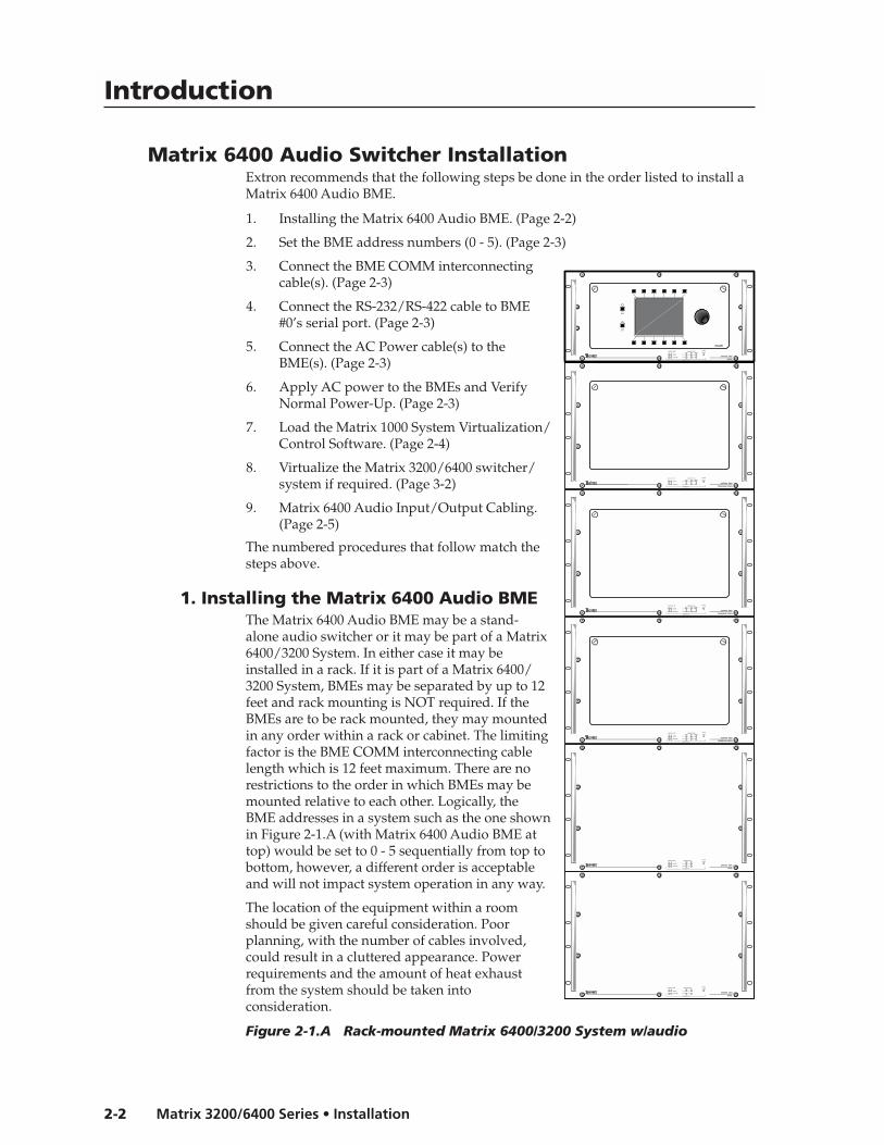
Matrix 6400 Audio Switcher InstallationExtron recommends that the following steps be done in the order listed to install aMatrix 6400 Audio BME.
1. Installing the Matrix 6400 Audio BME. (Page 2-2)
2. Set the BME address numbers (0 - 5). (Page 2-3)
3. Connect the BME COMM interconnectingcable(s). (Page 2-3)
4. Connect the RS-232/RS-422 cable to BME#0’s serial port. (Page 2-3)
5. Connect the AC Power cable(s) to theBME(s). (Page 2-3)
6. Apply AC power to the BMEs and VerifyNormal Power-Up. (Page 2-3)
7. Load the Matrix 1000 System Virtualization/Control Software. (Page 2-4)
8. Virtualize the Matrix 3200/6400 switcher/system if required. (Page 3-2)
9. Matrix 6400 Audio Input/Output Cabling.(Page 2-5)
The numbered procedures that follow match thesteps above.
1. Installing the Matrix 6400 Audio BMEThe Matrix 6400 Audio BME may be a stand-alone audio switcher or it may be part of a Matrix6400/3200 System. In either case it may beinstalled in a rack. If it is part of a Matrix 6400/3200 System, BMEs may be separated by up to 12feet and rack mounting is NOT required. If theBMEs are to be rack mounted, they may mountedin any order within a rack or cabinet. The limitingfactor is the BME COMM interconnecting cablelength which is 12 feet maximum. There are norestrictions to the order in which BMEs may bemounted relative to each other. Logically, theBME addresses in a system such as the one shownin Figure 2-1.A (with Matrix 6400 Audio BME attop) would be set to 0 - 5 sequentially from top tobottom, however, a different order is acceptableand will not impact system operation in any way.
The location of the equipment within a roomshould be given careful consideration. Poorplanning, with the number of cables involved,could result in a cluttered appearance. Powerrequirements and the amount of heat exhaustfrom the system should be taken intoconsideration.
Figure 2-1.A Rack-mounted Matrix 6400/3200 System w/audio
MATRIX 6400
WIDEBAND VIDEO
MATRIX 6400
WIDEBAND VIDEO
MATRIX 6400
WIDEBAND VIDEO
MATRIX 6400
SYNC
MATRIX 6400
SYNC
MATRIX 6400
AUDIO
POWER SUPPLIES COMMUNICATIONS
PRIMARY TX
RS232 BME REMOTE
SYSTEM
STATUS
REDUNDANT RX
DIAGNOSTICS
+V -V
POWER SUPPLIES COMMUNICATIONS
PRIMARY TX
RS232 BME REMOTE
SYSTEM
STATUS
REDUNDANT RX
DIAGNOSTICS
+V -V
POWER SUPPLIES COMMUNICATIONS
PRIMARY TX
RS232 BME REMOTE
SYSTEM
STATUS
REDUNDANT RX
DIAGNOSTICS
+V -V
POWER SUPPLIES COMMUNICATIONS
PRIMARY TX
RS232 BME
SYSTEM
STATUS
REDUNDANT RX
DIAGNOSTICS
+V -V
POWER SUPPLIES COMMUNICATIONS
PRIMARY TX
RS232 BME
SYSTEM
STATUS
REDUNDANT RX
DIAGNOSTICS
+V -V
POWER SUPPLIES COMMUNICATIONS
PRIMARY TX
RS232 BME REMOTE
SYSTEM
STATUS
REDUNDANT RX
DIAGNOSTICS
+V -V
FPC-1000
RGB
MUTE
AUDIO
MUTE
2-3Matrix 3200/6400 Series • Installation
The following restrictions apply to installing BMEs:
• One BME must be assigned as BME #0.
• BME #0 cannot be a Sync module.
• Address assignments must not skip numbers.
• Address assignments of 0 - 5 are accepted, BMEs w/address 6-9 are ignored.
• A system is limited to one audio module.
• A system may NOT include both Wideband video and Low Resolution videomodules.
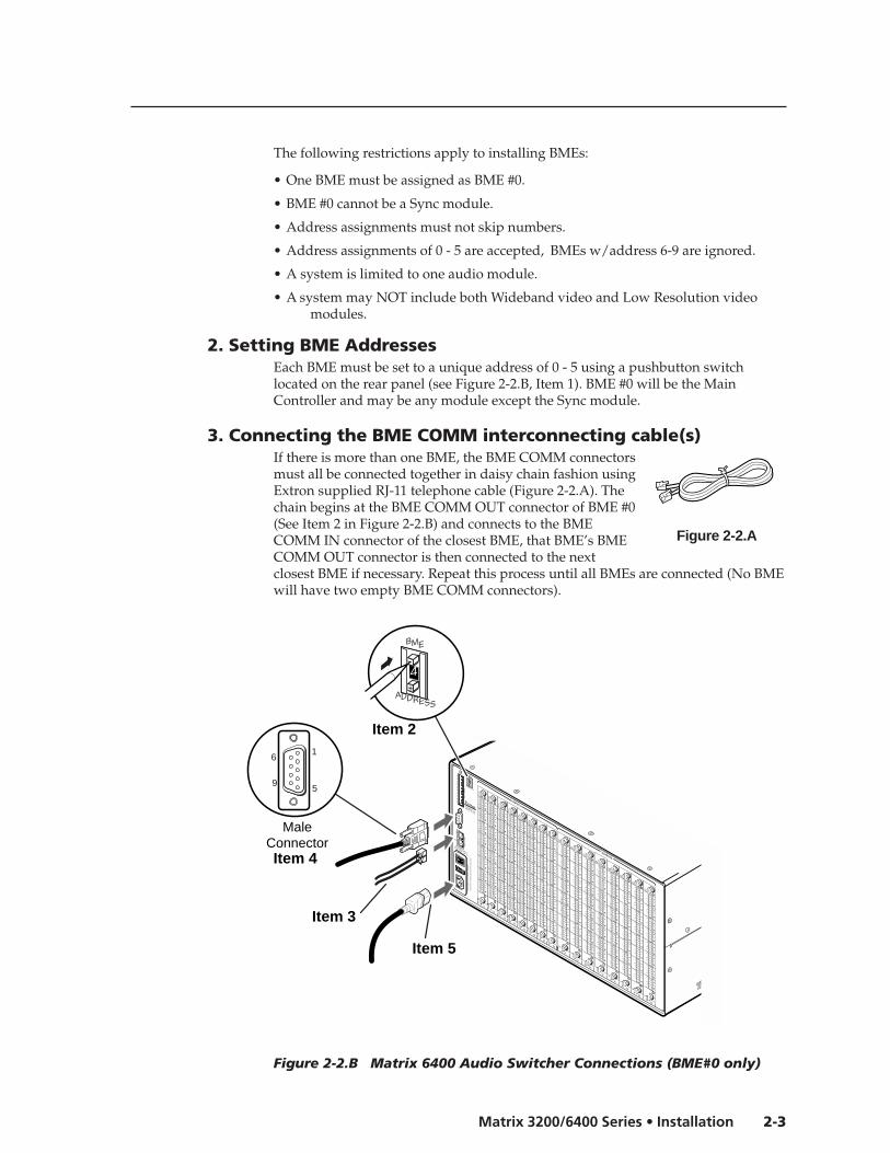
2. Setting BME AddressesEach BME must be set to a unique address of 0 - 5 using a pushbutton switchlocated on the rear panel (see Figure 2-2.B, Item 1). BME #0 will be the MainController and may be any module except the Sync module.
3. Connecting the BME COMM interconnecting cable(s)If there is more than one BME, the BME COMM connectorsmust all be connected together in daisy chain fashion usingExtron supplied RJ-11 telephone cable (Figure 2-2.A). Thechain begins at the BME COMM OUT connector of BME #0(See Item 2 in Figure 2-2.B) and connects to the BMECOMM IN connector of the closest BME, that BME’s BMECOMM OUT connector is then connected to the nextclosest BME if necessary. Repeat this process until all BMEs are connected (No BMEwill have two empty BME COMM connectors).
Figure 2-2.B Matrix 6400 Audio Switcher Connections (BME#0 only)
ANAHEIM, CA
MADE IN USA
AC POWER INPUT
FUSE: 250V 5.0A TT
10
0-2
40
V
0.5
A M
AX
5
0/6
0H
z
DIS
CO
NN
EC
T P
OW
ER
CO
RD
BE
FOR
E S
ER
VIC
ING
BME
ADDRESS
4
IN
OUT
BM
E C
OM
M.
MK
P C
OM
M.
A
B
C
D
E
A
B
C
D
E
IN
1 - 8
IN
9 - 16
IN
17 - 24
IN
25 - 32
IN
33 - 40
IN
41 - 48
IN
49 - 56
IN
57 - 64
OUT
1 - 8
OUT
9 - 16
OUT
17 - 24
OUT
25 - 32
OUT
33 - 40
OUT
41 - 48
OUT
49 - 56
OUT
57 - 64
INPUTS
OUTPUTS
4
BME
ADDRESS
MaleConnector
1
5
6
9
Item 2
Item 4
Item 3
Item 5
Figure 2-2.A

Installation, cont’d
Matrix 3200/6400 Series • Installation2-4
POWER SUPPLIES COMMUNICATIONS
PRIMARY TX
RS232 BME REMOTESYSTEMSTATUS
REDUNDANT RX
DIAGNOSTICS
+V -V
4. Connecting the RS-232/RS-422 Cable to BME #0Connect the cable from the Host PC computer serial port to the RS-232/RS-422connector on the rear panel of BME #0 as shown in Figure 2-2.B below (Item 3).After the BME(s) have been virtualized, they can be controlled through thisconnection using a PC Host or from a touch screen or any other user-suppliedcontrolling device, such as AMX, Crestron, etc., that is capable of generating theproper commands.
5. Connecting the AC Power Cable(s) to the BME(s)Each BME has its own internal power supply. Connect an AC Power cord to the ACpower receptacle on each BME (Item 4 in Figure 2-2.B). Connect the power cordplug to an AC power source.
6. Applying AC Power to the BME(s)Each BME has a power ON/OFF toggle switch on the rear panel just above the ACpower cord receptacle. BME #0 must be powered ON at the same time or after allother BMEs are ON. Press each power switch to the ON (1) position, Go to 6A onPage 2-4.
6A. BME Power-Up VerificationThe Diagnostics LEDs shown in Figure 2-3.A are located on the front panel of theMatrix 6400 Audio BME. The normal state of the LEDs after power-up is Primary+V and -V LEDs ON. If the BME includes a Redundant power supply, theRedundant +V and -V LEDswill also be ON. If the Primarypower supply fails, its LEDswill be OFF and theRedundant LEDs will blink.
The System Status LED willinitially blink indicating thatinternal housekeeping isoccurring, when it goes solidON, the system is ready.
Figure 2-3.A
7. Installing the Matrix 3200/6400 System Virtualization/ Con-trol Software
The Extron supplied software “Matrix 6400 Series Control Program” runs in theWindows® operating system, version 3.1 or later. Communication between thecomputer software and the switcher requires connecting a PC computer COMMport to the RS-232/RS-422 Port on the rear panel of module BME #0. Minimum PCsystem requirements are:
MATRIX 6400
AUDIO
POWER SUPPLIES COMMUNICATIONS
PRIMARY TX
RS232 BME REMOTE
SYSTEMSTATUS
REDUNDANT RX
DIAGNOSTICS
+V -V
FPC-1000
RGBMUTE
AUDIOMUTE

2-5Matrix 3200/6400 Series • Installation
486-33 MHz CPU or equivalent with 16 MB RAM5 MB Hard Disk space for software
If your Matrix 3200/6400 switcher was previously setup for RS-232, and yourPC Comm port uses RS-422, the switcher must be changed to match the PCinterface. The procedure for making the change begins on Page 5-2.
The first floppy disk (1 of 2) has instructions printed on the label. The softwaremust be installed onto the hard drive. It cannot be run from the floppy disk
1. Installing the software from the 3.5” floppy disk onto the hard disk is likemost other Windows programs. (Run Setup.exe from the first floppy disk.)
Figure 2-3.B
2. Installation of the software creates a Program Group (Windows 3.1) or aFolder (if Windows 95/98 or above) called “Extron Electronics”. Icons for theControl Program and the Help Program are installed in that group, or folder(Figure 2-3.B).
3. Double-click on the “mtrx6400.exe” icon to start the program. You will beasked to select the Comm Port, or choose “Emulate” mode. After selecting theCOMM port, the software looks for the matrix system, “reads” itsconfiguration, and then displays it in a window called “Extron’s MATRIX6400 Control Program”.
Emulate mode allows you to exercise the software without having a switcherconnected to the PC. It may also be used as a learning tool.
8. Virtualizing the Matrix 3200/6400 Switcher/SystemDetailed virtualization instructions begin on Page 3-2.
9. Matrix 6400 Audio Input/Output CablingUsing work-sheets and/or printouts from the Matrix 6400 System Virtualization/Control Program, install Audio input/output cables as required.
Using the Audio Captive Screw ConnectorsThe Matrix 6400 Audio Switcher consists of up to 8 input circuit cards and up to 8output circuit cards. Each card has a single vertical row of 3.5 mm audio receptacleswhich support 8 mono or stereo channels (depending on model selected) of inputor output audio (see Figures 2-4.A and 2-5.A). Each audio receptacle has contactswhich are labeled for channel (stereo only), polarity (+/–), and ground. The topcontacts on each circuit card are the lowest input or output number for thatparticular slot, for example, input 1 of the input card in slot 1 - 8, input 9 of the cardin slot 9 - 16, etc., or output 1 of the output card in slot 1 - 8, output 9 of the outputcard in slot 9 - 16 and so on.
See “Changing the Audio Output Card Gain Jumpers” on Page 5-10.
Captive screw audio connectors (3.5 mm, 5-pole #10-319-10, or 3-pole #10-265-03)are supplied with each audio switcher, one for each input and one for each output.The connectors must be wired to the audio cables using the captive screws insidethe connectors (see Figure 2-4.D or 2-5.B). Each captive screw audio connector willthen be plugged into the appropriate input or output position in the rear panel (seeFigure 2-4.B or 2-5.B). See wiring details and cautions that follow on next page.
Installation, cont’d
Matrix 3200/6400 Series • Installation2-6
AC POWER INPUTFUSE: 250V 5.0A TT
IN
OUT
100-
240V
5.0A
MA
X 5
0/60
Hz
DIS
CO
NN
EC
T P
OW
ER
CO
RD
BE
FOR
E S
ER
VIC
ING
MK
P C
OM
M.
BM
E C
OM
M.
RS
232/
RS
422
A
B
C
D
E
A
B
C
D
E
BME
ADDRESS
ANAHEIM, CAMADE IN USA
4-
+
INPUTS OUTPUTS
IN
1 - 8
IN
9 - 16
IN
17 - 24
IN
25 - 32
IN
33 - 40
IN
41 - 48
IN
49 - 56
IN
57 - 64
OUT
1 - 8
OUT
9 - 16
OUT
17 - 24
OUT
25 - 32
OUT
33 - 40
OUT
41 - 48
OUT
49 - 56
OUT
57 - 64
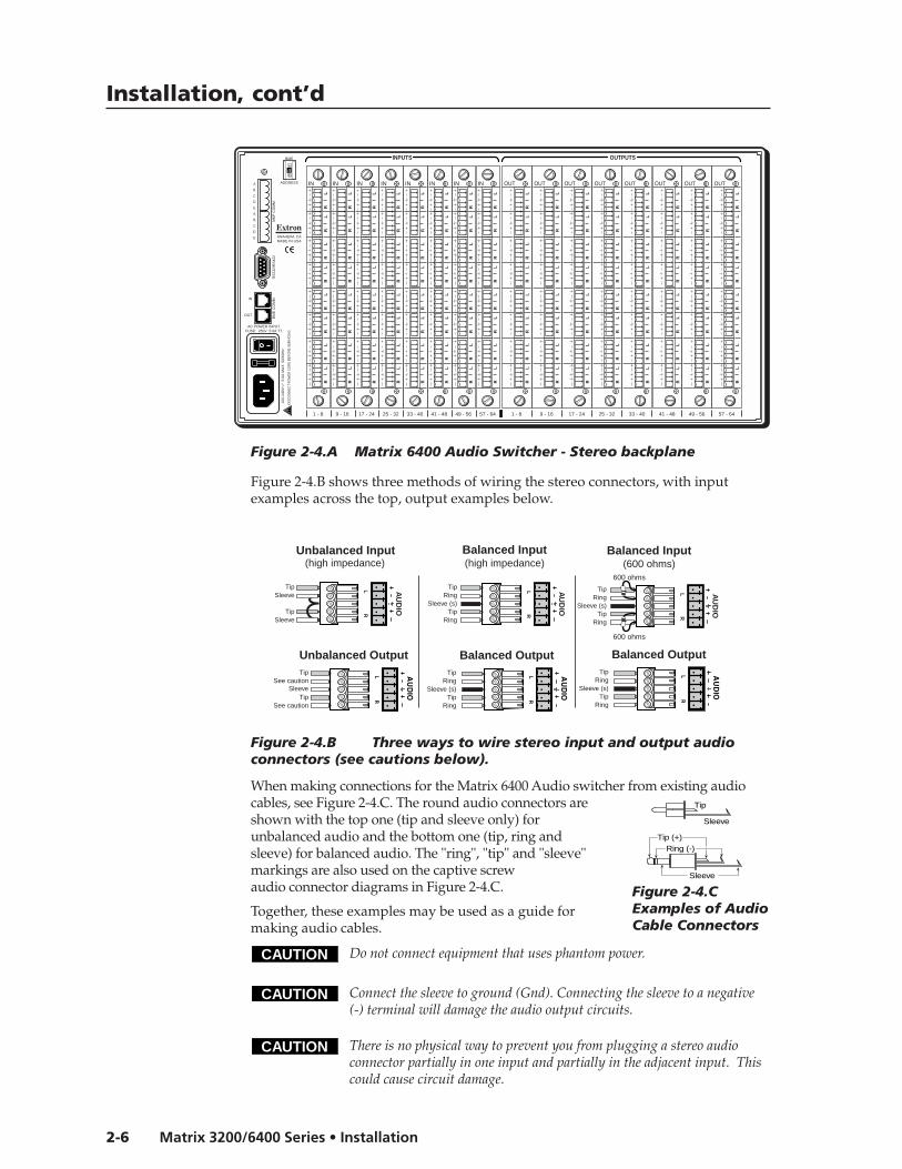
Figure 2-4.B shows three methods of wiring the stereo connectors, with inputexamples across the top, output examples below.
Figure 2-4.B Three ways to wire stereo input and output audioconnectors (see cautions below).
When making connections for the Matrix 6400 Audio switcher from existing audiocables, see Figure 2-4.C. The round audio connectors areshown with the top one (tip and sleeve only) forunbalanced audio and the bottom one (tip, ring andsleeve) for balanced audio. The "ring", "tip" and "sleeve"markings are also used on the captive screwaudio connector diagrams in Figure 2-4.C.
Together, these examples may be used as a guide formaking audio cables.
CAUTION Do not connect equipment that uses phantom power.
Tip
Sleeve
Ring (-)Tip (+)
Sleeve
Figure 2-4.CExamples of AudioCable Connectors
CAUTION Connect the sleeve to ground (Gnd). Connecting the sleeve to a negative(-) terminal will damage the audio output circuits.
CAUTION There is no physical way to prevent you from plugging a stereo audioconnector partially in one input and partially in the adjacent input. Thiscould cause circuit damage.
Figure 2-4.A Matrix 6400 Audio Switcher - Stereo backplane
LR
AU
DIO
LR
AU
DIO
LR
AU
DIO
Unbalanced Input
TipSleeve
TipSleeve
Balanced Input
TipRing
Sleeve (s)Tip
Ring
TipRing
Sleeve (s)Tip
Ring
Balanced Input(high impedance) (high impedance) (600 ohms)
600 ohms
600 ohms
Unbalanced OutputTip
See cautionSleeve
TipSee caution
Balanced OutputTip
RingSleeve (s)
TipRing
Balanced OutputTip
RingSleeve (s)
TipRing

2-7Matrix 3200/6400 Series • Installation
Figure 2-4.D Align the stereo audio connectors before plugging them in.
LR
LR
IN
LR
LR
IN
RingTip
Sleeve
Mono Input
RingTip
Sleeve
Mono Output
Figure 2-5.B Connecting mono input and output audio connectors
AC POWER INPUTFUSE: 250V 5.0A TT
IN
OUT
100-
240V
0.5A
MA
X 5
0/60
Hz
DIS
CO
NN
EC
T P
OW
ER
CO
RD
BE
FOR
E S
ER
VIC
ING
MK
P C
OM
M.
BM
E C
OM
M.
RS
232/
RS
422
A
B
C
D
E
A
B
C
D
E
BME
ADDRESS
ANAHEIM, CAMADE IN USA
4-
+
INPUTS OUTPUTS
IN
1 - 8
IN
9 - 16
IN
17 - 24
IN
25 - 32
IN
33 - 40
IN
41 - 48
IN
49 - 56
IN
57 - 64
OUT
1 - 8
OUT
9 - 16
OUT
17 - 24
OUT
25 - 32
OUT
33 - 40
OUT
41 - 48
OUT
49 - 56
OUT
57 - 64
MO
NO
MO
NO
MO
NO
MO
NO
MO
NO
MO
NO
MO
NO
MO
NO
MO
NO
MO
NO
MO
NO
MO
NO
MO
NO
MO
NO
MO
NO
MO
NO
MO
NO
MO
NO
MO
NO
MO
NO
MO
NO
MO
NO
MO
NO
MO
NO
MO
NO
MO
NO
MO
NO
MO
NO
MO
NO
MO
NO
MO
NO
MO
NO
MO
NO
MO
NO
MO
NO
MO
NO
MO
NO
MO
NO
MO
NO
MO
NO
MO
NO
MO
NO
MO
NO
MO
NO
MO
NO
MO
NO
MO
NO
MO
NO
MO
NO
MO
NO
MO
NO
MO
NO
MO
NO
MO
NO
MO
NO
MO
NO
MO
NO
MO
NO
MO
NO
MO
NO
MO
NO
MO
NO
MO
NO
MO
NO
MO
NO
MO
NO
MO
NO
MO
NO
MO
NO
MO
NO
MO
NO
MO
NO
MO
NO
MO
NO
MO
NO
MO
NO
MO
NO
MO
NO
MO
NO
MO
NO
MO
NO
MO
NO
MO
NO
MO
NO
MO
NO
MO
NO
MO
NO
MO
NO
MO
NO
MO
NO
MO
NO
MO
NO
MO
NO
MO
NO
MO
NO
MO
NO
MO
NO
MO
NO
MO
NO
MO
NO
MO
NO
MO
NO
MO
NO
MO
NO
MO
NO
MO
NO
MO
NO
MO
NO
MO
NO
MO
NO
MO
NO
MO
NO
MO
NO
MO
NO
MO
NO
MO
NO
MO
NO
MO
NO
MO
NO
MO
NO
MO
NO
MO
NO
MO
NO
MO
NO
MO
NO
MO
NO
MO
NO
MO
NO
Figure 2-5.A Matrix 6400 Audio Switcher - Mono backplane
IN
MO
NO
MO
NO
NO

Installation, cont’d
Matrix 3200/6400 Series • Installation2-8
Matrix 6400 Audio Switcher
3Chapter Three
Using the Matrix 3200/6400 SystemVirtualization/Control Software

Control Software, cont’d
Matrix 3200/6400 Series • Control Software3-2
Control Software
Tutorial - Using the Matrix 3200/6400 SystemVirtualization/Control Software
Extron’s Matrix 3200/6400 System Virtualization/ControlProgram
The Matrix 3200/6400 System Virtualization/Control program communicateswith the Extron Matrix 3200/6400 System through the RS-232/422 port on BME #0(defaults to 9600 baud, 8 bit, 1 stop, no parity). The program is required to initiallyset the Virtualization and optional Room configurations for the system. See thefollowing two sections for details:
• System Virtualization - creating a virtual I/O switching System - (see Page 3-3)
• Rooming - how to create Rooms - (see Page 3-5)The program also presents all the functions found on the optional Front-PanelController (FPC 1000), but in an interactive graphical interface, so it may be usedfor full control or initial programming of the system. Because settings to theMatrix (Ties, Presets, Audio config) are stored in the unit’s memory, several modesof ‘programming’ are possible. It provides 4 major methods:
• Remote control and programming of the system in real time through theRS-232 port.
• Saving system’s settings for later restoration to the same system (backup) orcopying to (programming) another system. Multiple configurations(programs) can be saved to disk and any one quickly reloaded later,providing an unlimited number of possible setups.
• Creating Program byte-strings for application to the Matrix system through athird-party control system.
• Emulation (off-line) programming of the system’s settings for copying tosystem at a later time or another place. Emulation mode also allows creationof programs for any possible Matrix hardware configuration without beingconnected to such a system.
To load a demonstration set of Ties, Presets and Rooms to your Matrix (or Emulateone) Restore from the DEMO6400.MTX file which was installed with the WindowsSoftware. Use NEW.INI to clear all settings in a unit.
Note that pressing the F1 key within the program will provide context-sensitiveHelp.
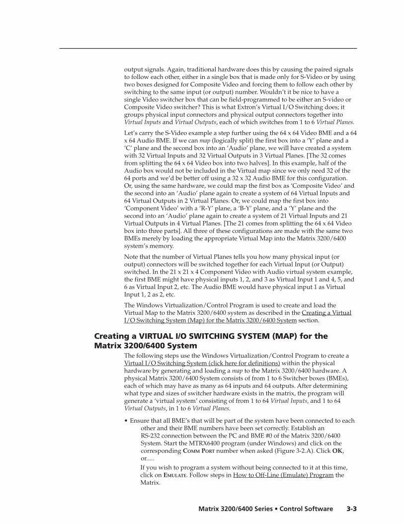
An Explanation of VIRTUAL I/O SWITCHING in the Matrix 3200/6400 System
A Matrix 3200/6400 System consists of from 1 to 6 Switcher boxes (BMEs), each ofwhich may have as many as 64 inputs and 64 outputs. It is usually desirable tohave certain inputs (or outputs) switch together as a set: to Follow each other. Forexample, if the system hardware consisted of a 64 x 64 Video BME and a 64 x 64Audio BME, you’d want your video monitor’s image and its audio speakers to becoming from the same source (maybe a VCR) and to follow each other whenswitched to another source (perhaps a Laser Disc player). This type of switchingrequires the two BMEs to communicate with each other so that they both switch tothe correct inputs to create the follow condition. In the traditional and simplestconfigurations, hardware is usually designed to cause both BMEs to switch to thesame input (or output) number.
An example where Follow mode is always required is with S-Video where the ‘Y’signal and the ‘C’ signal must be switched as a pair of input signals and a pair of
3-3Matrix 3200/6400 Series • Control Software
output signals. Again, traditional hardware does this by causing the paired signalsto follow each other, either in a single box that is made only for S-Video or by usingtwo boxes designed for Composite Video and forcing them to follow each other byswitching to the same input (or output) number. Wouldn’t it be nice to have asingle Video switcher box that can be field-programmed to be either an S-video orComposite Video switcher? This is what Extron’s Virtual I/O Switching does; itgroups physical input connectors and physical output connectors together intoVirtual Inputs and Virtual Outputs, each of which switches from 1 to 6 Virtual Planes.
Let’s carry the S-Video example a step further using the 64 x 64 Video BME and a 64x 64 Audio BME. If we can map (logically split) the first box into a ‘Y’ plane and a‘C’ plane and the second box into an ‘Audio’ plane, we will have created a systemwith 32 Virtual Inputs and 32 Virtual Outputs in 3 Virtual Planes. [The 32 comesfrom splitting the 64 x 64 Video box into two halves]. In this example, half of theAudio box would not be included in the Virtual map since we only need 32 of the64 ports and we’d be better off using a 32 x 32 Audio BME for this configuration.Or, using the same hardware, we could map the first box as ‘Composite Video’ andthe second into an ‘Audio’ plane again to create a system of 64 Virtual Inputs and64 Virtual Outputs in 2 Virtual Planes. Or, we could map the first box into‘Component Video’ with a ‘R-Y’ plane, a ‘B-Y’ plane, and a ‘Y’ plane and thesecond into an ‘Audio’ plane again to create a system of 21 Virtual Inputs and 21Virtual Outputs in 4 Virtual Planes. [The 21 comes from splitting the 64 x 64 Videobox into three parts]. All three of these configurations are made with the same twoBMEs merely by loading the appropriate Virtual Map into the Matrix 3200/6400system’s memory.
Note that the number of Virtual Planes tells you how many physical input (oroutput) connectors will be switched together for each Virtual Input (or Output)switched. In the 21 x 21 x 4 Component Video with Audio virtual system example,the first BME might have physical inputs 1, 2, and 3 as Virtual Input 1 and 4, 5, and6 as Virtual Input 2, etc. The Audio BME would have physical input 1 as VirtualInput 1, 2 as 2, etc.
The Windows Virtualization/Control Program is used to create and load theVirtual Map to the Matrix 3200/6400 system as described in the Creating a VirtualI/O Switching System (Map) for the Matrix 3200/6400 System section.
Creating a VIRTUAL I/O SWITCHING SYSTEM (MAP) for theMatrix 3200/6400 System
The following steps use the Windows Virtualization/Control Program to create aVirtual I/O Switching System (click here for definitions) within the physicalhardware by generating and loading a map to the Matrix 3200/6400 hardware. Aphysical Matrix 3200/6400 System consists of from 1 to 6 Switcher boxes (BMEs),each of which may have as many as 64 inputs and 64 outputs. After determiningwhat type and sizes of switcher hardware exists in the matrix, the program willgenerate a ‘virtual system’ consisting of from 1 to 64 Virtual Inputs, and 1 to 64Virtual Outputs, in 1 to 6 Virtual Planes.
• Ensure that all BME’s that will be part of the system have been connected to eachother and their BME numbers have been set correctly. Establish anRS-232 connection between the PC and BME #0 of the Matrix 3200/6400System. Start the MTRX6400 program (under Windows) and click on thecorresponding COMM PORT number when asked (Figure 3-2.A). Click OK,or.....If you wish to program a system without being connected to it at this time,click on EMULATE. Follow steps in How to Off-Line (Emulate) Program theMatrix.

Control Software, cont’d
Matrix 3200/6400 Series • Control Software3-4
• The program will communicate with the Matrix 3200/6400 System to determineits hardware configuration (type and size of each connected BME). It thenreads the system’s settings (Ties, Presets, Virtual Map, etc.) and draws agraphical representation of the unit’s configuration and settings (Ties) on theMain screen (Figure 3-5.A & B). It also reads the MTRX6400.INI file (savedfrom last session) to draw Icons for each I/O (if any had been applied inprevious programming sessions) to make the graphical representation evenmore friendly.
If this is a new system that has not been virtualized yet or one that has had itsmap cleared, the graphical representation and all information shown on theVirtual Map screen may be invalid at this time.
• From the menuon the Mainscreen, clickSYSTEM-CONFIG toshow theVirtual Mapscreen (seeFigure 3-4.A). Fromthe VirtualMap screenmenu, click CONFIGURE|PHYSICAL SWITCHERS to show the PhysicalConfiguration screen (Figure 3-3.A). Examine this screen to ensure that allBMEs were seen and their type and size is being reported as expected. Clickon the ‘Close’ button to return to the Virtual Map screen.
• From the Virtual Map screen menu, click CONFIGURE|VIRTUAL SWITCHER to showthe Virtual Configuration screen. This screen shows how the physical systemwill be mapped into a virtual system switcher by the Windows program (seeFigure 3-4.B). You may need to make some choices at this time that affect howmany virtual planes will be created and how many virtual inputs andoutputs will exist. For example, if a Sync BME was found, the program needsyou to decide whether to use composite sync (1 plane) or separate H and Vsync (2 planes).You need to decide how you want the initial map assignments organized,whether as ‘Repeat-Pattern’ (e.g. RGBRGB..B) or ‘Group-by-Plane’ (e.g.
FIGURE 3-2.A
FIGURE 3-3.A

3-5Matrix 3200/6400 Series • Control Software
Figure 3-4.A
Figure 3-4.B

Control Software, cont’d
Matrix 3200/6400 Series • Control Software3-6
Figure 3-5.A Main Screen - Ties
Figure 3-5.B Main Screen - Presets
3-7Matrix 3200/6400 Series • Control Software
RRRRGG..BBB). You may also change the ordering of the planes with thisscreen and affect which physical connectors get which signals. For example,in a Wideband system, instead of being in RGB order, you can change it toBGR order by using the radio buttons in each plane’s choices.
Note that you may play with the settings in this screen without causing anychanges to the system’s map until you press the ‘OK’ button. Even aftercommitting the changes and viewing them in the Virtual Map screen, you canstill return to this Virtual Configuration screen later and virtualize the systemdifferently. Changes can be made freely UNTIL you begin to make ties, savepresets, create rooms, or name your virtual inputs and outputs because thenumber of virtual inputs and outputs may be changed by re-virtualizing.Click on the ‘OK’ button to return to the Virtual Map screen.
• In the Virtual Map screen, examine the physical layout of the BMEs and how thevirtualization process assigned the input and output connectors to variousplanes. You can return to the Virtual Configuration screen if you wish tochange the mapping at this time by clicking CONFIGURE|VIRTUAL SWITCHER
again. If the map looks correct, you may optionally assign names (up to 12characters long) to any of the virtual inputs or outputs from the Virtual Mapscreen at any time. Names can also be read and edited from the system’sfront panel controller, if present.
• If you wish to group certain virtual outputs together so that you may later createRoom Presets, now would be a good time to Create ROOMS by clickingCONFIGURE|ROOM CONFIGURATION.
• You can create a hard-copy document that shows all the details from the VirtualMap screen at any time by clicking the PRINT MAPS menu. The printed mapsmake a very handy wiring guide and will appear in color if using a colorprinter. You can specify which printer to use from the FILE|SELECT PRINTER
menu in the Main screen.
• From the Virtual Map screen menu, click RETURN TO MAIN and note that thenumber of input and output boxes shown on the Main screen matches thenumber of virtual input and virtual outputs created by the virtualization. Thevirtualization of the system is now complete and the map has been stored inBME #0. Unless the map gets destroyed or needs to be regenerated because ofa system hardware reconfiguration (size, type, or number of BMEs changes)or you wish to change the virtual configuration, there is no requirement touse the Windows Virtualization/Control software. You can, however,continue to use it to control and program (set Ties, Presets, etc.) the system atany time.
How to Create ROOMS within the Matrix 3200/6400 SystemThe following steps use the Windows Virtualization/Control Program to optionallydefine Rooms in the Matrix 3200/6400 system. A Room is a group of virtual outputsthat are logically associated with each other, probably by location (such as 3 videomonitors and a VCR all located at a building’s security desk). A Room consists offrom 1 to 16 virtual outputs and the Matrix 3200/6400 supports up to 10 Rooms.Each Room can have a name (for user friendliness, up to 12 characters long) and upto 10 Presets assigned to it (for a total of 100 Room Presets). Unlike the 32 GlobalPresets, Room Presets only affect those virtual outputs associated with that Roomand do not change any other connections in the Matrix, making the use of Presetsmuch more simple and flexible. Room Presets are particularly useful in conjunctionwith the MKP-1000 keypads.
Rooms exist only to support Room Presets.
Control Software, cont’d
Matrix 3200/6400 Series • Control Software3-8
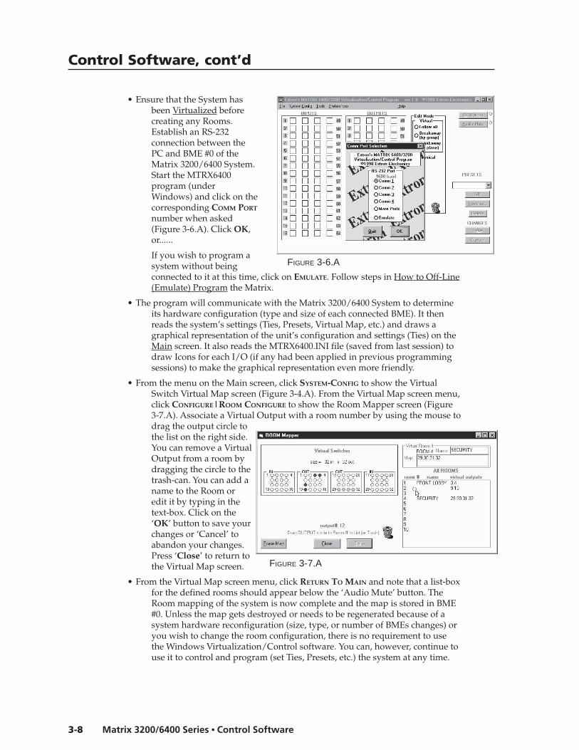
• Ensure that the System hasbeen Virtualized beforecreating any Rooms.Establish an RS-232connection between thePC and BME #0 of theMatrix 3200/6400 System.Start the MTRX6400program (underWindows) and click on thecorresponding COMM PORT
number when asked(Figure 3-6.A). Click OK,or......
If you wish to program asystem without beingconnected to it at this time, click on EMULATE. Follow steps in How to Off-Line(Emulate) Program the Matrix.
• The program will communicate with the Matrix 3200/6400 System to determineits hardware configuration (type and size of each connected BME). It thenreads the system’s settings (Ties, Presets, Virtual Map, etc.) and draws agraphical representation of the unit’s configuration and settings (Ties) on theMain screen. It also reads the MTRX6400.INI file (saved from last session) todraw Icons for each I/O (if any had been applied in previous programmingsessions) to make the graphical representation even more friendly.
• From the menu on the Main screen, click SYSTEM-CONFIG to show the VirtualSwitch Virtual Map screen (Figure 3-4.A). From the Virtual Map screen menu,click CONFIGURE|ROOM CONFIGURE to show the Room Mapper screen (Figure3-7.A). Associate a Virtual Output with a room number by using the mouse todrag the output circle tothe list on the right side.You can remove a VirtualOutput from a room bydragging the circle to thetrash-can. You can add aname to the Room oredit it by typing in thetext-box. Click on the‘OK’ button to save yourchanges or ‘Cancel’ toabandon your changes.Press ‘Close’ to return tothe Virtual Map screen.
• From the Virtual Map screen menu, click RETURN TO MAIN and note that a list-boxfor the defined rooms should appear below the ‘Audio Mute’ button. TheRoom mapping of the system is now complete and the map is stored in BME#0. Unless the map gets destroyed or needs to be regenerated because of asystem hardware reconfiguration (size, type, or number of BMEs changes) oryou wish to change the room configuration, there is no requirement to usethe Windows Virtualization/Control software. You can, however, continue touse it to control and program (set Ties, Presets, etc.) the system at any time.
FIGURE 3-7.A
FIGURE 3-6.A
3-9Matrix 3200/6400 Series • Control Software
How to Remotely CONTROL and PROGRAM the Matrix 3200/6400System
Because the Matrix 3200/6400 Switchers store their settings in a nonvolatilememory, programming applied to the unit from the Virtualization/ControlProgram (or the FPC) is remembered in the unit. The Program only needs to talk tothe Matrix system long enough to create (program) the settings. You can, however,leave a computer connected (dedicated) to the Matrix for real-time interactivecontrol and monitoring if you wish.
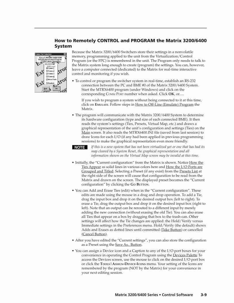
• To control or program the switcher system in real-time, establish an RS-232connection between the PC and BME #0 of the Matrix 3200/6400 System.Start the MTRX6400 program (under Windows) and click on thecorresponding COMM PORT number when asked. Click OK, or.....
If you wish to program a system without being connected to it at this time,click on EMULATE. Follow steps in How to Off-Line (Emulate) Program theMatrix.
• The program will communicate with the Matrix 3200/6400 System to determineits hardware configuration (type and size of each connected BME). It thenreads the system’s settings (Ties, Presets, Virtual Map, etc.) and draws agraphical representation of the unit’s configuration and settings (Ties) on theMain screen. It also reads the MTRX6400.INI file (saved from last session) todraw Icons for each I/O (if any had been applied in previous programmingsessions) to make the graphical representation even more friendly.
If this is a new system that has not been virtualized yet or one that has had itsmap cleared by a System Reset, the graphical representation and allinformation shown on the Virtual Map screen may be invalid at this time.
• Initially, the “Current configuration” from the Matrix is shown. Notice How theTies Appear as solid lines in various colors here and How the I/O Ports areGrouped and Titled. Selecting a Preset (if any exist) from the Presets List atthe right side of the screen will cause that configuration to be read from theMatrix and drawn on the screen. The displayed preset becomes the “Currentconfiguration” by clicking the GO BUTTON.
• You can Add and Erase Ties (edit) when in the “Current configuration”. Theseedits are made using the mouse in a drag and drop operation. To add a Tie,drag the input box and drop it on the desired output box (left to right). Toerase a Tie, drag the output box and drop it on the desired input box (right toleft). Note that an output can be rerouted to a different input by merelyadding the new connection (without erasing the old Tie). You can also eraseall Ties that appear on a box by dragging that box to the trash-can. Othersettings will affect how the Tie changes are applied: the Hold/Verify versusImmediate settings in the Preferences menu. Hold/Verify (the default) showsAdds and Erases as dotted lines until committed (Take Button) or cancelled(Cancel Button).
• After you have edited the “Current settings”, you can also store the configurationas a Preset using the Save As.. Button.
• You can assign a Device icon and a Caption to any of the I/O port boxes for yourconvenience in operating the Control Program using the Devices Palette Toaccess the Devices screen, use the mouse to click on the desired I/O port boxor click the TOOLS|ASSIGN-DEVICE-ICONS menu. Your setting of the Icons areremembered by the program (NOT by the Matrix) for your convenience inyour next editing session.
Control Software, cont’d
Matrix 3200/6400 Series • Control Software3-10
• If you have edited any of the configurations or assigned Icons or Captions, whenyou exit the program you will be prompted to save the changes. These will bewritten to the MTRX6400.INI file for use in your next editing session (if youagree). The information in the file also allows you to fully restore a Matrix3200/6400 System to all the settings (Ties, Presets, etc.) from the currentsession. We strongly recommend you allow the program to save yourchanges! You may also wish to Save the unit’s settings in a uniquely namedfile, instead.
How to PROGRAM the Matrix 3200/6400 System in EMULATEMODE
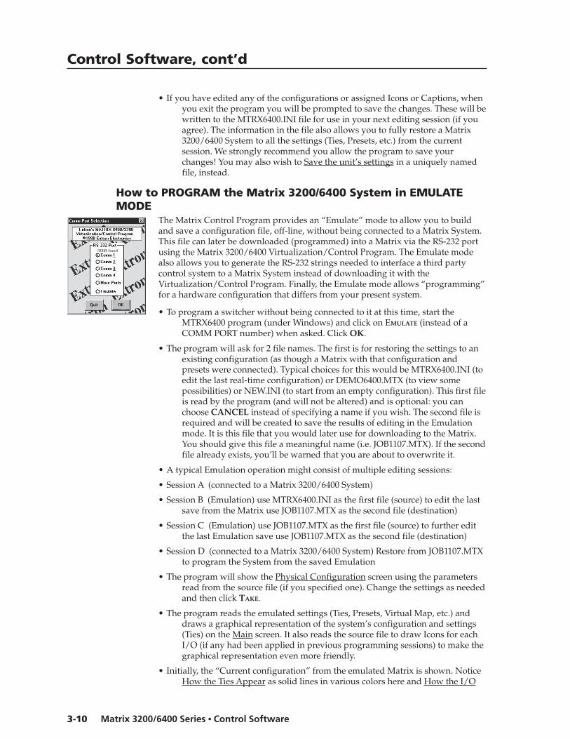
The Matrix Control Program provides an “Emulate” mode to allow you to buildand save a configuration file, off-line, without being connected to a Matrix System.This file can later be downloaded (programmed) into a Matrix via the RS-232 portusing the Matrix 3200/6400 Virtualization/Control Program. The Emulate modealso allows you to generate the RS-232 strings needed to interface a third partycontrol system to a Matrix System instead of downloading it with theVirtualization/Control Program. Finally, the Emulate mode allows “programming”for a hardware configuration that differs from your present system.
• To program a switcher without being connected to it at this time, start theMTRX6400 program (under Windows) and click on EMULATE (instead of aCOMM PORT number) when asked. Click OK.
• The program will ask for 2 file names. The first is for restoring the settings to anexisting configuration (as though a Matrix with that configuration andpresets were connected). Typical choices for this would be MTRX6400.INI (toedit the last real-time configuration) or DEMO6400.MTX (to view somepossibilities) or NEW.INI (to start from an empty configuration). This first fileis read by the program (and will not be altered) and is optional: you canchoose CANCEL instead of specifying a name if you wish. The second file isrequired and will be created to save the results of editing in the Emulationmode. It is this file that you would later use for downloading to the Matrix.You should give this file a meaningful name (i.e. JOB1107.MTX). If the secondfile already exists, you’ll be warned that you are about to overwrite it.
• A typical Emulation operation might consist of multiple editing sessions:
• Session A (connected to a Matrix 3200/6400 System)
• Session B (Emulation) use MTRX6400.INI as the first file (source) to edit the lastsave from the Matrix use JOB1107.MTX as the second file (destination)
• Session C (Emulation) use JOB1107.MTX as the first file (source) to further editthe last Emulation save use JOB1107.MTX as the second file (destination)
• Session D (connected to a Matrix 3200/6400 System) Restore from JOB1107.MTXto program the System from the saved Emulation
• The program will show the Physical Configuration screen using the parametersread from the source file (if you specified one). Change the settings as neededand then click TAKE.
• The program reads the emulated settings (Ties, Presets, Virtual Map, etc.) anddraws a graphical representation of the system’s configuration and settings(Ties) on the Main screen. It also reads the source file to draw Icons for eachI/O (if any had been applied in previous programming sessions) to make thegraphical representation even more friendly.
• Initially, the “Current configuration” from the emulated Matrix is shown. NoticeHow the Ties Appear as solid lines in various colors here and How the I/O
3-11Matrix 3200/6400 Series • Control Software
Ports are Grouped and Titled. Selecting a Preset (if any exist) from the PresetsList at the right side of the screen will cause that configuration to be readfrom the emulated Matrix and drawn on the screen. The displayed presetbecomes the “Current configuration” by clicking the GO BUTTON.
• You can Add and Erase ties (edit) when in the “Current configuration”. Theseedits are made using the mouse in a drag and drop operation. To add a Tie,drag the input box and drop it on the desired output box (left to right). Toerase a Tie, drag the output box and drop it on the desired input box (right toleft). Note that an output can be rerouted to a different input by merelyadding the new connection (without erasing the old Tie). Another setting willaffect how the Tie changes are applied: the Hold/Verify versus Immediatesettings in the Preferences menu. Hold/Verify (the default) shows Adds andErases as dotted lines until committed (Take Button) or cancelled (CancelButton)
• After you have edited the “Current settings”, you can also store the configurationas a Preset using the Save As.. Button.
• You can assign a Device icon and a Caption to any of the I/O port boxes for yourconvenience in operating the Control Program using the Devices Palette. Toaccess the Devices screen, use the mouse to click on the desired I/O PORT boxor click the TOOLS|ASSIGN-DEVICE-ICONS menu. Your setting of the Icons areremembered by the program (NOT by the Matrix) for your convenience inyour next editing session.
• If you have edited any of the configurations or assigned Icons or Captions, whenyou exit the program you will be prompted to save the changes. These will bewritten to the Emulation file for use in your next editing session (if youagree). The information in the file also allows you to fully restore a Matrix3200/6400 System to all the settings (Ties, Presets, etc.) from the currentsession We strongly recommend you allow the program to save yourchanges! You may also wish to Save the unit’s settings in a uniquely namedfile, instead.
How to SAVE and RESTORE the Matrix 3200/6400 SettingsThe FILE menu provides the following functions:
• Save MATRIX settings as... (uploads *.MTX file from system)
• Restore MATRIX settings from... (downloads *.MTX file to system)
• Save This Session’s settings (uploads MTRX6400.INI file from unit)
• Restore Last Session’s settings (downloads MTRX6400.INI file to unit)In normal operation (non-emulation mode), the Virtualization/Control Programreads the MTRX6400.INI file at start-up to display Icons since these items do notcause any changes in the Matrix System’s configuration (programming) andprovide convenience to the user. The file actually contains all the informationneeded to fully Restore (program) the Matrix 3200/6400 System’s settings. Both ofthe Restore functions in the menu cause a FULL Restore of the attached MatrixSystem, providing an easy method to switch between (reprogram) configurations.
Both of the Save functions in the menu create a complete .INI type file for futurerestoration to an attached Matrix. By default, the SAVE AS choice uses fileextension .MTX, but any name and extension can be used when saving or restoringa file. The SAVE THIS function is not usually needed since the program promptsyou to create one upon exiting if any edits were performed. The RESTORE LASTfunction allows you to set your Matrix configuration back to its settings when youfirst started the Virtualization/Control Program (effectively cancelling any editsand changes without leaving the program).
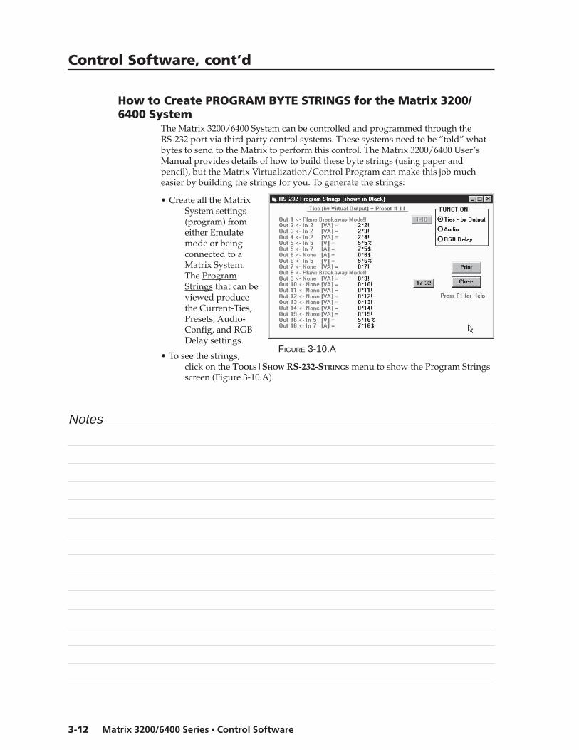
Control Software, cont’d
Matrix 3200/6400 Series • Control Software3-12
How to Create PROGRAM BYTE STRINGS for the Matrix 3200/6400 System
The Matrix 3200/6400 System can be controlled and programmed through theRS-232 port via third party control systems. These systems need to be “told” whatbytes to send to the Matrix to perform this control. The Matrix 3200/6400 User’sManual provides details of how to build these byte strings (using paper andpencil), but the Matrix Virtualization/Control Program can make this job mucheasier by building the strings for you. To generate the strings:
• Create all the MatrixSystem settings(program) fromeither Emulatemode or beingconnected to aMatrix System.The ProgramStrings that can beviewed producethe Current-Ties,Presets, Audio-Config, and RGBDelay settings.
• To see the strings,click on the TOOLS|SHOW RS-232-STRINGS menu to show the Program Stringsscreen (Figure 3-10.A).
Notes
FIGURE 3-10.A

Matrix 6400 Audio Switcher
4Chapter Four
RS-232/RS-422 Programmer’s Guide
Serial Communications Port
Host-to-Switcher Communications
Command/Response Table
Error Codes
Switcher Initiated Messages

Programmer’s Guide, cont’d
Matrix 3200/6400 Series • Programmer’s Guide4-2
Programmer’s Guide
Serial Communications PortIf the Matrix 6400 Audio Switcher is the Master BME (BME #0), its RS-232/RS-422connector may be connected to the serial port output of a Host device such as acomputer or control panel. Software control of the switcher is made possible by thisconnection. A Host serial port connection to the RS-232/RS-422 connector of aMatrix 6400 Audio Switcher is shown in Figure 4-1.A.
The Matrix 6400 Audio Switcher is normally configured for RS-232 control. Ifit is to be used with an RS-422 device, an internal cable must be moved. Theprocedure for moving the cable begins on Page 5-2.
The RS-232/422 connector on the Matrix 6400 Audio Switcher is a 9-pinD female with the following pin assignments:
Pin RS-232 Description RS-422 Description1 – not used Tx(-) Transmit Data (-)2 Tx Transmit Data Tx(+) Transmit Data (+)3 Rx Receive Data Rx(+) Receive Data (+)4 – not used Rx(-) Receive Data (-)5 Gnd Signal Ground Gnd Ground6 – not used – not used7 – not used – not used8 – not used – not used9 – not used – not used
The protocol is 9600 baud, 8-bit, 1 stop bit, no parity and no Flow control.
Details for programming the Matrix 6400 Audio Switcher from a Host systemconnected to the RS-232/RS-422 port are covered in this chapter.
Figure 4-1.A Matrix 6400 Audio Switcher RS-232/RS-422 to Hostconnection
To HostSystem/DeviceSerial Port
MaleConnector
1
5
6
9
ANAHEIM, CA
MADE IN USA
AC POWER INPUT
FUSE: 250V 5.0A TT
100-2
40V
0.5
A M
AX
50/6
0H
z
DIS
CO
NN
EC
T P
OW
ER
CO
RD
BE
FOR
E S
ER
VIC
ING
BME
ADDRESS
4
IN
OUT
BM
E C
OM
M.
MK
P C
OM
M.
A
B
C
D
E
A
B
C
D
E
IN
1 - 8
IN
9 - 16
IN
17 - 24
IN
25 - 32
IN
33 - 40
IN
41 - 48
IN
49 - 56
IN
57 - 64
OUT
1 - 8
OUT
9 - 16
OUT
17 - 24
OUT
25 - 32
OUT
33 - 40
OUT
41 - 48
OUT
49 - 56
OUT
57 - 64
INPUTS
OUTPUTS
FemaleConnector
1
5
6
9
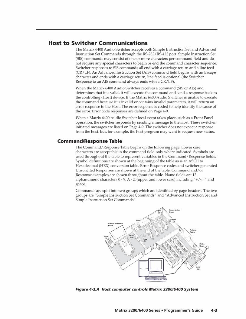
4-3Matrix 3200/6400 Series • Programmer’s Guide
Host to Switcher CommunicationsThe Matrix 6400 Audio Switcher accepts both Simple Instruction Set and AdvancedInstruction Set Commands through the RS-232/RS-422 port. Simple Instruction Set(SIS) commands may consist of one or more characters per command field and donot require any special characters to begin or end the command character sequence.Switcher responses to SIS commands all end with a carriage return and a line feed(CR/LF). An Advanced Instruction Set (AIS) command field begins with an Escapecharacter and ends with a carriage return, line feed is optional (the SwitcherResponse to an AIS command always ends with a CR/LF).
When the Matrix 6400 Audio Switcher receives a command (SIS or AIS) anddetermines that it is valid, it will execute the command and send a response back tothe controlling (Host) device. If the Matrix 6400 Audio Switcher is unable to executethe command because it is invalid or contains invalid parameters, it will return anerror response to the Host. The error response is coded to help identify the cause ofthe error. Error code responses are defined on Page 4-9.
When a Matrix 6400 Audio Switcher local event takes place, such as a Front Paneloperation, the switcher responds by sending a message to the Host. These switcherinitiated messages are listed on Page 4-9. The switcher does not expect a responsefrom the host, but, for example, the host program may want to request new status.
Command/Response TableThe Command/Response Table begins on the following page. Lower casecharacters are acceptable in the command field only where indicated. Symbols areused throughout the table to represent variables in the Command/Response fields.Symbol definitions are shown at the beginning of the table as is an ASCII toHexadecimal (HEX) conversion table. Error Response codes and switcher generatedUnsolicited Responses are shown at the end of the table. Command and/orResponse examples are shown throughout the table. Name fields are 12alphanumeric characters 0 - 9, A - Z (upper and lower case) including “+/-:=” andspace.
Commands are split into two groups which are identified by page headers. The twogroups are “Simple Instruction Set Commands” and “Advanced Instruction Set andSimple Instruction Set Commands”.
Figure 4-2.A Host computer controls Matrix 3200/6400 System
PresentationRoom
Video ConferenceRoom
TrainingRoom
MediaRoom
Extron
Electronics
COMPAQ PCCOMPAQ PC
COMPAQ PC
Player 2DVDPlayer 3
VCR
Player 1VCR
LaserDevice Controller
DSS
HORIZONTAL Sync
VERTICAL SyncAUDIO
GREEN
BLUE
RED
A
C
Input1-6
Input7-9
Input10
DB
Input11
Input13
Input14
12
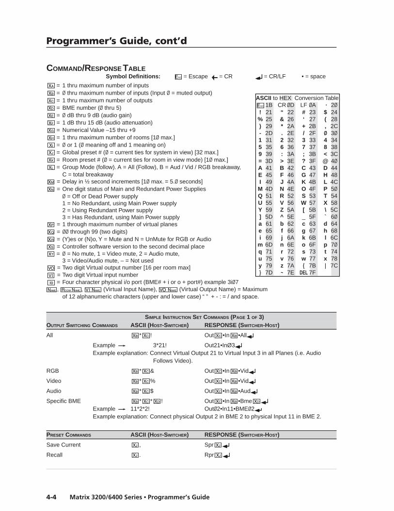
Programmer’s Guide, cont’d
Matrix 3200/6400 Series • Programmer’s Guide4-4
COMMAND/RESPONSE TABLESymbol Definitions: = Escape = CR = CR/LF • = space
= 1 thru maximum number of inputs= Ø thru maximum number of inputs (Input Ø = muted output)= 1 thru maximum number of outputs= BME number (Ø thru 5)= Ø dB thru 9 dB (audio gain)= 1 dB thru 15 dB (audio attenuation)= Numerical Value –15 thru +9= 1 thru maximum number of rooms [1Ø max.]= Ø or 1 (Ø meaning off and 1 meaning on)= Global preset # (Ø = current ties for system in view) [32 max.]= Room preset # (Ø = current ties for room in view mode) [1Ø max.]= Group Mode (follow). A = All (Follow), B = Aud / Vid / RGB breakaway,
C = total breakaway = Delay in ½ second increments [1Ø max. = 5.Ø seconds] = One digit status of Main and Redundant Power Supplies
Ø = Off or Dead Power supply1 = No Redundant, using Main Power supply2 = Using Redundant Power supply3 = Has Redundant, using Main Power supply
= 1 through maximum number of virtual planes = ØØ through 99 (two digits) = (Y)es or (N)o, Y = Mute and N = UnMute for RGB or Audio = Controller software version to the second decimal place= Ø = No mute, 1 = Video mute, 2 = Audio mute,
3 = Video/Audio mute, – = Not used = Two digit Virtual output number [16 per room max] = Two digit Virtual input number = Four character physical i/o port (BME# + i or o + port#) example 3iØ7, , (Virtual Input Name), (Virtual Output Name) = Maximum
of 12 alphanumeric characters (upper and lower case) “ ” + - : = / and space.
ASCII to HEX Conversion Table1B CR ØD LF ØA · 2Ø
! 21 “ 22 # 23 $ 24% 25 & 26 ‘ 27 ( 28) 29 * 2A + 2B , 2C- 2D . 2E / 2F Ø 3Ø1 31 2 32 3 33 4 345 35 6 36 7 37 8 389 39 : 3A ; 3B < 3C= 3D > 3E ? 3F @ 4ØA 41 B 42 C 43 D 44E 45 F 46 G 47 H 48I 49 J 4A K 4B L 4C
M 4D N 4E O 4F P 5ØQ 51 R 52 S 53 T 54U 55 V 56 W 57 X 58Y 59 Z 5A [ 5B \ 5C] 5D ^ 5E _ 5F ` 6Øa 61 b 62 c 63 d 64e 65 f 66 g 67 h 68i 69 j 6A k 6B l 6C
m 6D n 6E o 6F p 7Øq 71 r 72 s 73 t 74u 75 v 76 w 77 x 78y 79 z 7A { 7B | 7C} 7D ~ 7E DEL 7F
SIMPLE INSTRUCTION SET COMMANDS (PAGE 1 OF 3)OUTPUT SWITCHING COMMANDS ASCII (HOST-SWITCHER) RESPONSE (SWITCHER-HOST)
All * ! Out •In •All
Example 3*21! Out21•InØ3Example explanation: Connect Virtual Output 21 to Virtual Input 3 in all Planes (i.e. Audio
Follows Video).
RGB * & Out •In •Vid
Video * % Out •In •Vid
Audio * $ Out •In •Aud
Specific BME * * ! Out •In •BmeExample 11*2*2! OutØ2•In11•BMEØ2Example explanation: Connect physical Output 2 in BME 2 to physical Input 11 in BME 2.
PRESET COMMANDS ASCII (HOST-SWITCHER) RESPONSE (SWITCHER-HOST)
Save Current , Spr
Recall . Rpr
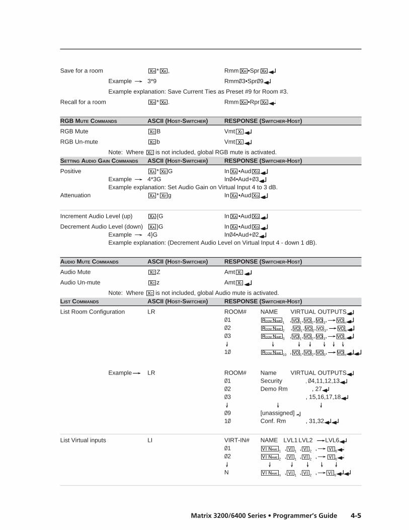
4-5Matrix 3200/6400 Series • Programmer’s Guide
Save for a room * , Rmm •Spr
Example 3*9 RmmØ3•SprØ9
Example explanation: Save Current Ties as Preset #9 for Room #3.
Recall for a room * . Rmm •Rpr
RGB MUTE COMMANDS ASCII (HOST-SWITCHER) RESPONSE (SWITCHER-HOST)
RGB Mute B Vmt
RGB Un-mute b Vmt
Note: Where is not included, global RGB mute is activated.SETTING AUDIO GAIN COMMANDS ASCII (HOST-SWITCHER) RESPONSE (SWITCHER-HOST)
Positive * G In •AudExample 4*3G InØ4•Aud+Ø3Example explanation: Set Audio Gain on Virtual Input 4 to 3 dB.
Attenuation * g In •Aud
Increment Audio Level (up) {G In •Aud
Decrement Audio Level (down) }G In •AudExample 4}G InØ4•Aud+Ø2Example explanation: (Decrement Audio Level on Virtual Input 4 - down 1 dB).
AUDIO MUTE COMMANDS ASCII (HOST-SWITCHER) RESPONSE (SWITCHER-HOST)
Audio Mute Z Amt
Audio Un-mute z Amt
Note: Where is not included, global Audio mute is activated.LIST COMMANDS ASCII (HOST-SWITCHER) RESPONSE (SWITCHER-HOST)
List Room Configuration LR ROOM# NAME VIRTUAL OUTPUTSØ1 1 , 1, 2, 3, n
Ø2 2 , 1, 2, 3, n
Ø3 3 , 1, 2, 3, n
1Ø 10 , 1, 2, 3, n
Example LR ROOM# Name VIRTUAL OUTPUTSØ1 Security , Ø4,11,12,13Ø2 Demo Rm , 27Ø3 , 15,16,17,18
Ø9 [unassigned]1Ø Conf. Rm , 31,32
List Virtual inputs LI VIRT-IN# NAME LVL1 LVL2 LVL6Ø1 1 , 1 , 2 , 6
Ø2 2 , 1 , 2 , 6
N n , 1 , 2 , 6
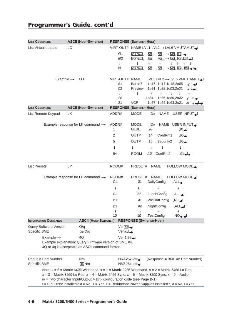
Programmer’s Guide, cont’d
Matrix 3200/6400 Series • Programmer’s Guide4-6
LIST COMMANDS ASCII (HOST-SWITCHER) RESPONSE (SWITCHER-HOST)
List Virtual outputs LO VIRT-OUT# NAME LVL1 LVL2 LVL6 VMUTAMUT
Ø1 1 , 1 , 2, 6, Ø2 2 , 1 , 2, 6, ,
N n , 1 , 2, 6, ,
Example LO VIRT-OUT# NAME LVL1 LVL2 LVL6 VMUT AMUTØ1 Barco7 ,1o16 ,1o17,1o18,2oØ5 ,y,nØ2 Preview ,1oØ1 ,1oØ2,1oØ3,2oØ1 ,y,y
2Ø ,1oØ4 ,1oØ5,1oØ6,2oØ2 ,y ,n21 VCR ,1oØ7 ,1o62,1o63,2o21 ,n ,y
LIST COMMANDS ASCII (HOST-SWITCHER) RESPONSE (SWITCHER-HOST)
List Remote Keypad LK ADDR# MODE ID# NAME USER INPUT
Example response for LK command ADDR# MODE ID# NAME USER INPUT 1 GLBL ,ØØ , ,Ø1
2 OUTP ,14 ,ConfRm1 ,Ø5
5 OUTP ,15 , Security2 ,Ø5
64 ROOM ,1Ø ,ConfRm2 ,Ø1
List Presets LP ROOM# PRESET# NAME FOLLOW MODE
Example response for LP command ROOM# PRESET# NAME FOLLOW MODE GL Ø1 ,DailyConfig ,ALL
GL 32 ,LunchConfig ,ALL
Ø1 Ø1 ,WkEndConfig ,NO
Ø1 Ø2 ,NightConfig ,ALL 1Ø 1Ø ,TestConfig ,NO
INFORMATION COMMANDS ASCII (HOST-SWITCHER) RESPONSE (SWITCHER-HOST)
Query Software Version Q/q VerSpecific BME Q/q Ver
Example 4Q Ver 1.ØØExample explanation: Query Firmware version of BME #4.4Q or 4q is acceptable as ASCII command format.
Request Part Number N/n N6Ø-25x-iofr (Response = BME #Ø Part Number)Specific BME N/n N6Ø-25x-iofr
Note: x = Ø = Matrix 64ØØ Wideband, x = 1 = Matrix 32ØØ Wideband, x = 2 = Matrix 64ØØ Lo Res,x = 3 = Matrix 32ØØ Lo Res, x = 4 = Matrix 64ØØ Sync, x = 5 = Matrix 32ØØ Sync, x = 6 = Audio.io = Two character Input/Output Matrix configuration code (see Page B-1)f = FPC-1ØØØ installed?, Ø = No, 1 = Yes r = Redundant Power Supplies installed?, Ø = No,1 =Yes.

4-7Matrix 3200/6400 Series • Programmer’s Guide
INFORMATION COMMANDS ASCII (HOST-SWITCHER) RESPONSE (SWITCHER-HOST)
Request Information I/i I X •T •U •M
X •Vmt •Amt •Sys •Dgn
Example I I64X64•T1•U2•M21X21•VmtØ•Amt1•Sys1•DgnØØ
Example explanation: I64X64 indicates that this BME has 64 physical inputs and 64 physical outputs.T1= Wideband Switcher, U2 indicates system has 2 BMEs and is set to M21X21 (21 Virtual Inputs and21 Virtual Outputs). VmtØ = Video is not Muted, Amt1 = Audio is Muted. Sys1 indicates that this BMEhas no redundant power supply and the main power supply is on. DgnØØ indicates no error (BME’s self-test diagnostics passed. Dgn2Ø if reported = System physical size has changed since last virtualized.
Specific BME I/i Same as Request Information Response above.Notes:1. Command “ØI ” is equivalent to “I” or “i” command.2. 1 = Wideband, 2 = Lo-Res, 3 = Sync, 4 = Audio (for this BME), Ø = BME not present.3. + is physical size of this BME.4. , , , , are each two digit fields.
ADVANCED INSTRUCTION SET AND SIMPLE INSTRUCTION SET COMMANDS (PAGE 1 OF 3)VIEW COMMANDS ASCII (HOST-SWITCHER) RESPONSE (SWITCHER-HOST)
Audio Gain V/v G In ·Aud
Example V15G In15•Aud-Ø6Example explanation: Virtual Input 15 Audio Level is set to -6 dB.
Global PRESET information VI ,Grp
Example ØVI Jims_Lecture,GrpA
Global PRESET Ties * *ØØVA SO• SO+1• SO+2 • SO+15•All
Views are 16 virtual outputs at a time; each position shows what virtual input is connected to that virtual output.
Preset Ø views the current configuration.
Example 1 Ø*Ø1*ØØVA
Example 1 explanation: Read Preset Ø (current) Ties of Virtual Inputs to Virtual Outputs Ø1 through 16 in Follow mode.
Example 2 Ø*17*ØØVA
Example 2 explanation: Read Preset Ø (current) Ties of Virtual Inputs to Virtual Outputs 17 through 32 in Follow mode.
Example 3 3*49*ØØVA
Example 3 explanation: Read Preset 3 Ties of Virtual Inputs to Virtual Outputs 49 through 64 in Follow mode.
Global PRESET w/Total Breakaway * * VC SO• SO+1• SO+2 • SO+15•Plane Command description preset*start-output*plane
Global PRESET by Specific BME * * VD SO• SO+1• SO+2 • SO+15•Bme Command description preset*start-output*BME#
Room PRESET information * VI ,Grp
Room PRESET Ties * *Ø1*ØØVA Rvo • Rvo....•All
Room PRESET w/Total Breakaway * *Ø1* VC Rvo • Rvo....•Plane Command description room*preset*start-output*plane
Ø4•64•ØØ•ØØ•ØØ•ØØ•Ø3•Ø1•ØØ•ØØ•ØØ•64•ØØ•Ø1•ØØ•ØØ•All↵
virtual input #4 tied to virtual output #17
virtual input #64 tied to virtual output #18
no virtual input tied to virtual output #32
Ø4•--•ØØ•ØØ•ØØ•--•Ø3•Ø1•na•na•na•na•na•na•na•na•All↵
virtual input #4 tied to virtual output #49
virtual output #50 does not have audio follow (see note 3 below)
in a 64 virtual input x 56 virtual output configuration,the last 8 virtual outputs are nonexistent (see note 2 below)
virtual input #4 tied to virtual output #1
virtual input #64 tied to virtual output #2
no virtual input tied to virtual output #16
Ø4•64•ØØ•ØØ•ØØ•ØØ•Ø3•Ø1•ØØ•ØØ•ØØ•64•ØØ•Ø1•ØØ•ØØ•All↵
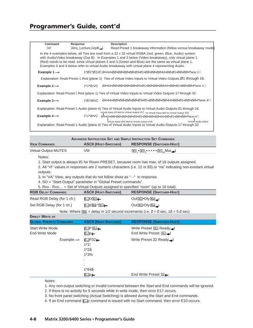
Programmer’s Guide, cont’d
Matrix 3200/6400 Series • Programmer’s Guide4-8
ADVANCED INSTRUCTION SET AND SIMPLE INSTRUCTION SET COMMANDS
VIEW COMMANDS ASCII (HOST-SWITCHER) RESPONSE (SWITCHER-HOST)
Virtual Output MUTES VM 1• 2• • • • • 64Mut
Notes:1. Start output is always Ø1 for Room PRESET, because room has max. of 16 outputs assigned.2. All “VI” values in responses are 2 numeric characters (i.e. 12 or Ø3) or “na” indicating non-existant virtualoutputs.3. In “VA” View, any outputs that do not follow show as “- -“ in response.4. SO = “Start-Output” parameter in “Global Preset commands”.5. Rvo - Rvo.... = Set of Virtual Outputs assigned to specified “room” (up to 16 total).
RGB DELAY COMMANDS ASCII (HOST-SWITCHER) RESPONSE (SWITCHER-HOST)
Read RGB Delay (for 1 ch.) D Out •Dly
Set RGB Delay (for 1 ch.) d * Out •Dly
Note: Where = delay in 1/2 second increments (i.e. Ø = Ø sec, 1Ø = 5.Ø sec)DIRECT WRITE OF
GLOBAL PRESETS COMMANDS ASCII (HOST-SWITCHER) RESPONSE (SWITCHER-HOST)
Start Write Mode P Write Preset ReadyEnd Write Mode p End Write Preset
Example P32 Write Preset 32 Ready1*1!1*2&1*3%::1*64$
p End Write Preset 32
Notes:1. Any non-output switching or invalid command between the Start and End commands will be ignored.2. If there is no activity for 5 seconds while in write mode, then error E17 occurs.3. No front panel switching (Actual Switching) is allowed during the Start and End commands.4. If an End command p command is issued with no Start command, then error E10 occurs.
Ø4•64•ØØ•ØØ•ØØ•ØØ•Ø3•Ø1•ØØ•ØØ•ØØ•64•ØØ•Ø1•ØØ•ØØ•Plane 1↵
Ø4•64•ØØ•ØØ•ØØ•ØØ•Ø3•Ø1•ØØ•ØØ•ØØ•64•ØØ•Ø1•ØØ•ØØ•Plane 1↵
Ø4•64•ØØ•ØØ•ØØ•ØØ•Ø3•Ø1•ØØ•ØØ•ØØ•64•ØØ•Ø1•ØØ•ØØ•Plane 4↵
Ø4•64•ØØ•ØØ•ØØ•ØØ•Ø3•Ø1•ØØ•ØØ•ØØ•64•ØØ•Ø1•ØØ•ØØ•Plane 4↵virtual input #4 tied to virtual output #17
virtual input #64 tied to virtual output #18
no virtual input tied to virtual output #32
virtual audio plane
Command Response Description1VI Jims_Lecture,GrpB Read Preset 1 breakaway information (follow versus breakaway mode)
In the 4 examples below, all Ties are read from a 32 x 32 virtual RGBA (red, green, Blue, Audio) systemwith Audio/Video breakaway (Grp B). In Examples 1 and 2 below (Video breakaway), only virtual plane 1(Red) needs to be read, since virtual planes 2 and 3 (Green and Blue) are the same as virtual plane 1.Examples 3 and 4 below refer to virtual Audio breakaway with virtual plane 4 representing Audio.
Example 1 1*Ø1*Ø1VC
Explanation: Read Preset 1 Red (plane 1) Ties of Virtual Video Inputs to Virtual Video Outputs Ø1 through 16.
Example 2 1*17*Ø1VC
Explanation: Read Preset 1 Red (plane 1) Ties of Virtual Video Inputs to Virtual Video Outputs 17 through 32.
Example 3 1*Ø1*Ø4VC
Explanation: Read Preset 1 Audio (plane 4) Ties of Virtual Audio Inputs to Virtual Audio Outputs Ø1 through 16.
Example 4 1*17*Ø4VC
Explanation: Read Preset 1 Audio (plane 4) Ties of Virtual Audio Inputs to Virtual Audio Outputs 17 through 32.

4-9Matrix 3200/6400 Series • Programmer’s Guide
QUICK RECALL OF
GLOBAL PRESETS COMMANDS ASCII (HOST-SWITCHER) RESPONSE (SWITCHER-HOST)
Quick Recall Preset . Rpr
Notes:1. If the Quick Recall Preset ( .) command is issued without an active write, then error E10 occurs.2. Complete backplane switch within 60mSeconds (apprx.) after receipt of the command.3. Recall must take place 100mSeconds after End Write Mode command ( p ).4. Quick recall command only recalls last entered direct write preset.
SET NAMES COMMANDS ASCII (HOST-SWITCHER) RESPONSE (SWITCHER-HOST)Read Global preset name NGWrite Global preset name nG , NamPRead Room preset name NP *Write Room preset name nP * , NamPRead Room Name NRWrite Room Name nR , NamRRead Virtual Input Name NIWrite Virtual Input Name nI , NamIRead Virtual Output Name NOWrite Virtual Output Name nO , NamO
ADVANCED INSTRUCTION SET AND SIMPLE INSTRUCTION SET COMMANDS (PAGE 3 OF 3)ZAP CONFIGURATION COMMANDS ASCII (HOST-SWITCHER) RESPONSE (SWITCHER-HOST)
Zap All Global presets & names zG ZapG
Zap individual Global zT ZapT
Zap All Room presets & names zP ZapP
Zap individual Room Preset zT * ZapT
Zap All RGB Delay to Ø sec. zD ZapD
Zap all Audio Gains to Ø dB. zA ZapA
UnMute RGB/Audio (All Mutes) zZ ZapZ
Master Reset zXXX ZapXXXERROR CODES
If the switcher receives a command that is invalid or contains invalid parameters, it will return an Error Coderesponse. The error code response has the format “Exx”. Following is a list of possible error code responses.
Description of Error code
EØ1 Invalid input channel number (too large)EØ5 Device is offE1Ø Invalid commandE11 Invalid preset number (too large)E12 Invalid output number (too large)E13 Value too large (Gain)E14 Command not available for matrix configurationE2Ø Invalid BME numberE21 Invalid Room numberE22 BusyE23 Checksum error
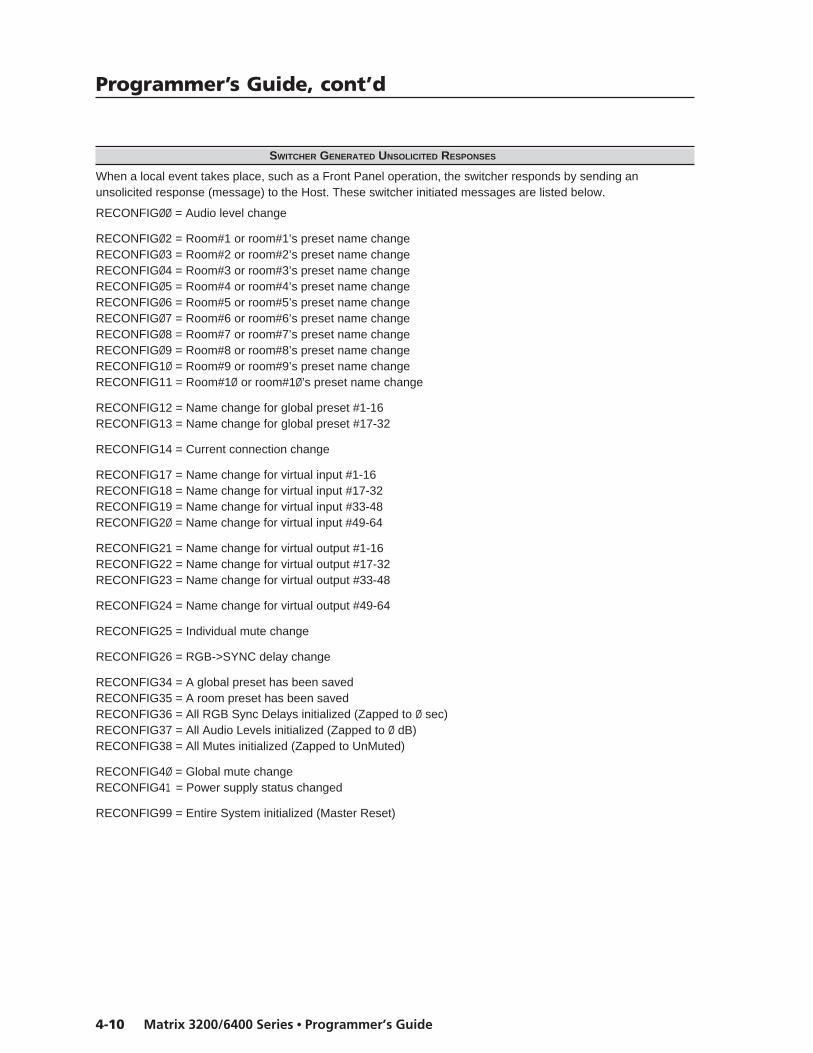
Programmer’s Guide, cont’d
Matrix 3200/6400 Series • Programmer’s Guide4-10
SWITCHER GENERATED UNSOLICITED RESPONSES
When a local event takes place, such as a Front Panel operation, the switcher responds by sending anunsolicited response (message) to the Host. These switcher initiated messages are listed below.
RECONFIGØØ = Audio level change
RECONFIGØ2 = Room#1 or room#1’s preset name changeRECONFIGØ3 = Room#2 or room#2’s preset name changeRECONFIGØ4 = Room#3 or room#3’s preset name changeRECONFIGØ5 = Room#4 or room#4’s preset name changeRECONFIGØ6 = Room#5 or room#5’s preset name changeRECONFIGØ7 = Room#6 or room#6’s preset name changeRECONFIGØ8 = Room#7 or room#7’s preset name changeRECONFIGØ9 = Room#8 or room#8’s preset name changeRECONFIG1Ø = Room#9 or room#9’s preset name changeRECONFIG11 = Room#1Ø or room#1Ø’s preset name change
RECONFIG12 = Name change for global preset #1-16RECONFIG13 = Name change for global preset #17-32
RECONFIG14 = Current connection change
RECONFIG17 = Name change for virtual input #1-16RECONFIG18 = Name change for virtual input #17-32RECONFIG19 = Name change for virtual input #33-48RECONFIG2Ø = Name change for virtual input #49-64
RECONFIG21 = Name change for virtual output #1-16RECONFIG22 = Name change for virtual output #17-32RECONFIG23 = Name change for virtual output #33-48
RECONFIG24 = Name change for virtual output #49-64
RECONFIG25 = Individual mute change
RECONFIG26 = RGB->SYNC delay change
RECONFIG34 = A global preset has been savedRECONFIG35 = A room preset has been savedRECONFIG36 = All RGB Sync Delays initialized (Zapped to Ø sec)RECONFIG37 = All Audio Levels initialized (Zapped to Ø dB)RECONFIG38 = All Mutes initialized (Zapped to UnMuted)
RECONFIG4Ø = Global mute changeRECONFIG41 = Power supply status changed
RECONFIG99 = Entire System initialized (Master Reset)

Matrix 6400 Audio Switcher
5Chapter Five
Upgrades and Troubleshooting
Upgrade and Troubleshooting Procedures
Installing Software Update (IC Chip)
Swapping RS-232/RS-422 Ports
Changing the AC Fuse
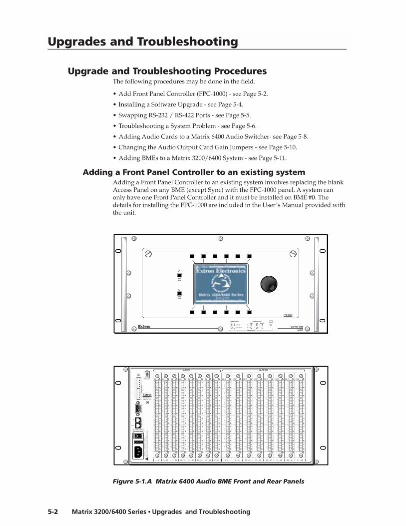
Upgrades and Troubleshooting, cont’d
Matrix 3200/6400 Series • Upgrades and Troubleshooting5-2
Upgrades and Troubleshooting
Upgrade and Troubleshooting ProceduresThe following procedures may be done in the field.
• Add Front Panel Controller (FPC-1000) - see Page 5-2.
• Installing a Software Upgrade - see Page 5-4.
• Swapping RS-232 / RS-422 Ports - see Page 5-5.
• Troubleshooting a System Problem - see Page 5-6.
• Adding Audio Cards to a Matrix 6400 Audio Switcher- see Page 5-8.
• Changing the Audio Output Card Gain Jumpers - see Page 5-10.
• Adding BMEs to a Matrix 3200/6400 System - see Page 5-11.
Adding a Front Panel Controller to an existing systemAdding a Front Panel Controller to an existing system involves replacing the blankAccess Panel on any BME (except Sync) with the FPC-1000 panel. A system canonly have one Front Panel Controller and it must be installed on BME #0. Thedetails for installing the FPC-1000 are included in the User’s Manual provided withthe unit.
Figure 5-1.A Matrix 6400 Audio BME Front and Rear Panels
MATRIX 6400
AUDIO
POWER SUPPLIES COMMUNICATIONS
PRIMARY TX
RS232 BME REMOTE
SYSTEMSTATUS
REDUNDANT RX
DIAGNOSTICS
+V -V
FPC-1000
RGBMUTE
AUDIOMUTE
AC POWER INPUTFUSE: 250V 5.0A TT
IN
OUT
100-
240V
0.5A
MA
X 5
0/60
Hz
DIS
CO
NN
EC
T P
OW
ER
CO
RD
BE
FOR
E S
ER
VIC
ING
MK
P C
OM
M.
BM
E C
OM
M.
RS
232/
RS
422
A
B
C
D
E
A
B
C
D
E
BME
ADDRESS
ANAHEIM, CAMADE IN USA
4-
+
INPUTS OUTPUTS
IN
1 - 8
IN
9 - 16
IN
17 - 24
IN
25 - 32
IN
33 - 40
IN
41 - 48
IN
49 - 56
IN
57 - 64
OUT
1 - 8
OUT
9 - 16
OUT
17 - 24
OUT
25 - 32
OUT
33 - 40
OUT
41 - 48
OUT
49 - 56
OUT
57 - 64
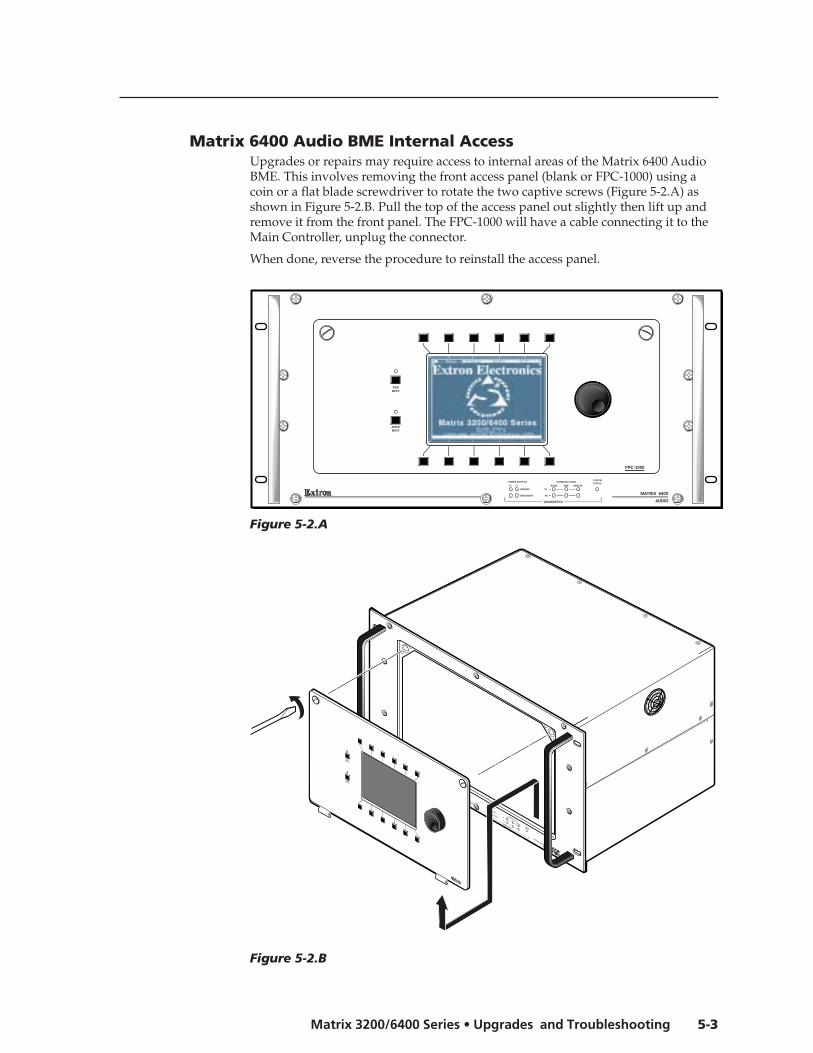
5-3Matrix 3200/6400 Series • Upgrades and Troubleshooting
Matrix 6400 Audio BME Internal AccessUpgrades or repairs may require access to internal areas of the Matrix 6400 AudioBME. This involves removing the front access panel (blank or FPC-1000) using acoin or a flat blade screwdriver to rotate the two captive screws (Figure 5-2.A) asshown in Figure 5-2.B. Pull the top of the access panel out slightly then lift up andremove it from the front panel. The FPC-1000 will have a cable connecting it to theMain Controller, unplug the connector.
When done, reverse the procedure to reinstall the access panel.
Figure 5-2.A
Figure 5-2.B
MATRIX 6400
AUDIO
POWER SUPPLIES COMMUNICATIONS
PRIMARY TX
RS232 BME REMOTE
SYSTEMSTATUS
REDUNDANT RX
DIAGNOSTICS
+V -V
FPC-1000
RGBMUTE
AUDIOMUTE
RGBMUTE
AUDIOMUTE

Upgrades and Troubleshooting, cont’d
Matrix 3200/6400 Series • Upgrades and Troubleshooting5-4
Installing A Software UpdateTo install a software update, IC U9 or U6 (or both) on the Main Control printedcircuit card is replaced. If the system consists of multiple BMEs, the software IC(s)in each BME’s Main Control PCB may need to be updated. Use the followingprocedure to replace the Matrix 6400 Audio Main Control PCB IC(s).
1. Power the system OFF and unplug the AC power cord.2. Remove the Access Panel. See Page 5-3.3. Use the PLCC IC puller (Figure 5-3.A) to remove the existing Software IC.
Squeeze the tool to align the hooks with the slots provided in oppositecorners of IC socket U9 or U6. Insert the hooks, squeeze gently and pull the ICstraight out of the socket. Set the IC aside.
4. Note the key (angled corner) of the new Software IC. Orient this to match the keyof the socket and carefully press it in place.
5. Reinstall the Access Panel.6. Plug in the AC power cord, power the system ON.7. Verify that the switcher is working properly.
Figure 5-3.A Updating the Software IC on the Main Control Card
1
2
19J1
20
HIGH VOLTAGE
CAUTION
HIGH VOLTAGE
CAUTION
RED -J16
MAIN +J13
Main Control Card
RED +J14 U9
U6MAIN -J15
To DiagnosticsLEDs
J1
J4
J5
J8
POWER SUPPLIES
COMMUNICATIONS
PRIMARY
TX RS232
BMEREMOTE
SYSTEMSTATUS
REDUNDANT
RX
DIAGNOSTICS
+V-V

5-5Matrix 3200/6400 Series • Upgrades and Troubleshooting
Swapping BME #0 RS-232 / RS-422 PortsSwapping BME #0 RS-232/RS-422 ports (not required on BME #1 - BME #5)involves moving a ribbon cable from one Main Control card connector to another.
Ribbon Cable ConnectorsThe ribbon cables used in the Matrix 6400 Audio Switcher use a self-latching stylereceptacle. Figure 5-4.A shows how it operates.
1. Press each of the two tabs outward, this unlocksthe receptacle and ejects the ribbon cableconnector part way. Pull evenly on the ribboncable connector to remove it.
2. When reconnecting the cable, first align the pinsin the receptacle with the holes in the connectorand press evenly into the receptacle until thereceptacle tabs lock the connector in place.
Swapping Serial Ports (RS-232/RS-422)Before working inside, unplug the power cord.
The Matrix 6400 Audio Switcher is normally connected for RS-232 use. If yourapplication requires RS-422, follow this procedure (and Figure 5-4.B) to change theconfiguration. The procedure for removing and installing the ribbon cables isdescribed above in “Ribbon Cable Connectors” above.
1. Power OFF BME #0, unplug the power cord.
2. Remove the Access Panel on BME #0 (Page 5-3), locate the Main Control card(see Figure 5-3.A).
3. Locate ribbon cable receptacles J4 and J5 (Figure 5-4.B). One is empty and theother has a ribbon cable which goes to the rear panel. The ribbon cable plugsinto J4 for RS-232 and J5 for RS-422. If the connection is wrong for yourapplication, disconnect the cable and move it to the other receptacle.
4. Reinstall the Access Panel.
5. Plug in the AC power cord, power ON the BME.
Figure 5-4.B Main Control Card (for card location, see Figure 5-3.A)
RED -J16
MAIN +J13
RED +J14
U9
RS-422
RS-232
To RS-232/RS-422Connector
MAIN -J15
To Diagnostics LEDs
J1J4
J5
J8

Upgrades and Troubleshooting, cont’d
Matrix 3200/6400 Series • Upgrades and Troubleshooting5-6
Troubleshooting a Matrix 3200/6400 System ProblemAll Matrix 3200/6400 BME front panels include LEDs at the bottom of the panelwhich are bracketed and labeled DIAGNOSTICS. These LEDs (Figure 5-6.A)indicate the current status of the BME power supplies, the RS232/BME/MKP1
Communications RX and TX lines, and the System Status. The followingdescriptions include normal/failure/status conditions for each LED.
Power SuppliesPrimary +V Green LED ON = Normal
OFF = Failure
Primary -V Green LED ON = NormalOFF = Failure
Redundant +V Green LED ON = NormalOFF = Failure (or Redundant not present)Blinking = Redundant +V supplying full +V load(indicates Primary +V power supply failure)
Redundant -V Green LED ON = NormalOFF = Failure (or Redundant not present)Blinking = Redundant -V supplying full +Vload (indicates Primary -V power supply failure)
If a BME fails to power ON, check the BME external AC fuse (see Page 5-7).If the Diagnostic LEDs indicate that a power supply has failed, check the powersupply fuse (see Page 5-7).
BME #0 must be powered ON at the same time or after other BMEs. Any BMEpowered on after BME #0 will not be seen by the internal system software.
CommunicationsRS232 TX - Red LED ON/Blinking = BME is transmitting data to HostRS232 RX - Green LED ON/Blinking = BME is receiving data from HostBME TX - Red LED ON/Blinking = BME is transmitting dataBME RX - Green LED ON/Blinking = BME is receiving dataMKP TX - Red LED ON/Blinking = BME is transmitting to Remote keypad
MKP RX - Green LED ON/Blinking = BME is receiving from Remote keypad
1. MKP TX/RX LEDs are not present on SYNC BMEs.2. MKP LED conditions above apply only to BME #0.3. RS-232 LED conditions above apply only to BME #0.4. A communications failure between BME #0 and other BMEs could becaused by one BME loading down the BME TX or RX line. To determine ifthat is the case, run the RJ-11 BME COMM interconnecting cable to bypasseach BME one at a time.
System StatusAmber LED ON = Normal
OFF = System failure - Call Extron Tech SupportBlinking = Busy
Checking/Replacing the BME External AC Input FuseThe AC power input cord plugs into the Power-Switch/Fuse assembly which islocated on the rear panel in the lower left corner of the BME. To check/replace theexternal fuse, remove the power-cord and insert the tip of a small screwdriver blade

5-7Matrix 3200/6400 Series • Upgrades and Troubleshooting
into the fuse-holder slot (the fuse-holder is located just below the powerswitch). Pry the fuse-holder out, it contains the AC input fuse plus aspare. If may be obvious that the fuse is blown, if not, check it with anohmmeter or any other continuity device if available. If the fuse isblown, replace it with the provided spare. Plug the AC power cord inand Power the BME ON. Verify that the unit powered ON correctly(check Front Panel LEDs). If the LEDs are in the proper state, theproblem has been corrected. If not, contact Extron Technical Support.
Checking/Replacing the BME Internal Power Supply AC InputFuses
Each internal power supply has an AC input fuse. If a power supply fuse blows,the Front Panel LED for that power supply will go OFF (it is normally solid ON). Ifthe BME has redundant power supplies, the redundant supply for the failed powersupply will assume the full load and its front panel diagnostic LED will blinkindicating that the Main (Primary) power supply is inoperative. To check/replace apower supply fuse, unplug the AC power cord from the BME rear panel, removethe Access Panel (see Page 5-3). The power supply fuse location is shown in Figure5-6.A (circled). Remove the fuse from the problem power supply. If may be obviousthat the fuse is blown, if not, check it with an ohmmeter or any other continuitydevice if available. If the fuse is blown, replace it, plug the AC power cord in,power up the BME and check Diagnostic LEDs. If the problem persists, call ExtronTechnical Support.
AC POWER INPUTFUSE: 250V 0.8A TT
100-
240V
0.5A
MA
X 5
0/60
Hz
Figure 5-6.A BMEexploded view
1
2
19J1
20
HIGH VOLTAGE
CAUTION
HIGH VOLTAGE
CAUTION
Fuse
POWER SUPPLIES
COMMUNICATIONS
PRIMARY
TX RS232
BMEREMOTE
SYSTEMSTATUS
REDUNDANT
RX
DIAGNOSTICS
+V-V
POWER SUPPLIES COMMUNICATIONS
PRIMARY TX
RS232 BME REMOTESYSTEMSTATUS
REDUNDANT RX
DIAGNOSTICS
+V -V
Primary V+Power Supply
Redundant V+Power Supplywould be located here
Primary V-Power Supply(Redundant V-would be located besidePrimary V-)

Upgrades and Troubleshooting, cont’d
Matrix 3200/6400 Series • Upgrades and Troubleshooting5-8
Matrix 6400 Audio Switcher Upgrade - Changing theMatrix Size
Changing the matrix size of a Matrix 6400 Audio Switcher may require adding orremoving input and/or output audio circuit cards. Page 5-9 describes theprocedure for determining the required number of input and output cards for thedesired matrix size and which connectors the cards should be plugged into. Thefollowing procedure describes how to change the matrix size.
1. See Page 5-12 “Software Procedure - Before and After a HardwareUpgrade”. Do steps under “Before Hardware Changes” prior to making anyhardware changes.
To ignore step 1 and proceed with the hardware upgrade will requireconsiderable system reconfiguration time. It is highly recommended that younot skip any step.
2. Turn OFF the AC power switch and unplug the AC power cord.
Installing or removing Audio cards with power on may damage the equipment.
3. Plug the audio cards in as required (see page 5-9).
4. Plug the AC power cord in and turn ON the AC power switch.
5. Do the steps under “After Hardware Changes” on Page 5-13.
6. Verify that the new matrix size is correctly identified by the software.
ANAHEIM, CA
MADE IN USA
AC POWER INPUT
FUSE: 250V 5.0A TT
10
0-2
40
V
0.5
A M
AX
5
0/6
0H
z
DIS
CO
NN
EC
T P
OW
ER
CO
RD
BE
FOR
E S
ER
VIC
ING
BME
ADDRESS
4
IN
OUT
BM
E C
OM
M.
MK
P C
OM
M.
A
B
C
D
E
A
B
C
D
E
Align with plastic guides
IN
1 - 8
IN
9 - 16
IN
17 - 24
IN
25 - 32
IN
33 - 40
IN
41 - 48
IN
49 - 5657 - 64
OUT
1 - 8
OUT
9 - 16
OUT
17 - 24
OUT
25 - 32
OUT
33 - 40
OUT
41 - 48
OUT
49 - 56
OUT
57 - 64
INPUTS
OUTPUTS
IN
Figure 5-7.A Inserting an audio card into slot 57-64.

5-9Matrix 3200/6400 Series • Upgrades and Troubleshooting
Determining Audio Switcher Circuit CardPopulation
The drawing above shows the layout of the inputand output audio circuit card slots on the rearpanel of the Matrix 6400 Audio Switcher. The 8 cardslots to the left are bracketed and labeled INPUTS,the 8 card slots to the right are bracketed andlabeled OUTPUTS. Each audio card supports 8stereo channels and each card slot (input andoutput) is labeled to identify the physical connectorrange covered by the card plugged into a slot (lownumber = top connector, high number = bottomconnector on card).
The chart to the right shows the REQUIRED circuitcard population for every possible matrixconfiguration. The following Matrix 6400 Audioconfigurations are supported:
8 inputs x 8, 16, 24, 32, 40, 48, 56, 64 outputs16 inputs x 8, 16, 24, 32, 40, 48, 56, 64 outputs24 inputs x 8, 16, 24, 32, 40, 48, 56, 64 outputs32 inputs x 8, 16, 24, 32, 40, 48, 56, 64 outputs40 inputs x 8, 16, 24, 32, 40, 48, 56, 64 outputs48 inputs x 8, 16, 24, 32, 40, 48, 56, 64 outputs56 inputs x 8, 16, 24, 32, 40, 48, 56, 64 outputs64 inputs x 8, 16, 24, 32, 40, 48, 56, 64 outputs
An example matrix configuration of 24x16 wouldrequire audio input cards in the left 3 slots (1-8, 9-16 and 17-24) of the INPUTS section and audiooutput cards in the left 2 slots (1-8 and9-16) of the OUTPUTS section. If the cards are notinstalled as shown for each matrix size, the ExtronMatrix 6400 System Virtualization/ControlSoftware will be unable to accurately virtualize thesystem. The Audio Input circuit cards (PN# 70-069-01) plug into connectors INPUTS 1-8 through 57-64,the Audio Output circuit cards (PN# 70-070-01)plug into connectors OUTPUTS 1-8 through 57-64.It is not possible to plug the circuit cards in upsidedown or inputs into outputs nor vice versa.
AC POWER INPUTFUSE: 250V 5.0A TT
IN
OUT
100-
240V
5.0A
MA
X 5
0/60
Hz
DIS
CO
NN
EC
T P
OW
ER
CO
RD
BE
FOR
E S
ER
VIC
ING
MK
P C
OM
M.
BM
E C
OM
M.
RS
232/
RS
422
A
B
C
D
E
A
B
C
D
E
BME
ADDRESS
ANAHEIM, CAMADE IN USA
4-
+
INPUTS OUTPUTS
IN
1 - 8
IN
9 - 16
IN
17 - 24
IN
25 - 32
IN
33 - 40
IN
41 - 48
IN
49 - 56
IN
57 - 64
OUT
1 - 8
OUT
9 - 16
OUT
17 - 24
OUT
25 - 32
OUT
33 - 40
OUT
41 - 48
OUT
49 - 56
OUT
57 - 64

Upgrades and Troubleshooting, cont’d
Matrix 3200/6400 Series • Upgrades and Troubleshooting5-10
Changing the Audio Output Card Gain JumpersThe gain indicated by an FPC 1000 LCD panel or a Host computer running Extron’sMatrix 6400 System Control software may be off by 6dB depending on the type ofoutput (balanced or unbalanced) and jumper positions on the Audio Output card. Ifthe Audio card jumpers for each output are set to match the output type, theindicated gain will match the actual gain for all outputs.
Each Audio Output card has eight pairs of jumpers (one pair for each stereo, twochannel output on the card) which enables the gain to be changed by 6dB for eachoutput. The pairs consist of headers H9 and H10, H11 and H12, H13 and H14through H23 and H24 (jumper locations are shown in Figure 5-9.A below). Thejumpers plug onto header pins 1 and 2 (upper position) or 2 and 3 (lower position)and each position’s affect on the output signal follows:
Jumper on pins 1 and 2, output gain will be 0dB unbalanced and +6dB balanced.Jumper on pins 2 and 3, output gain will be –6dB unbalanced and 0dB balanced.
Jumpers for unbalanced output go on pins 1 and 2, balanced on pins 2 and 3. TheMatrix 6400 Audio switchers ship with all gain jumpers on header pins 1 & 2.
If a particular output’s gain is going to be changed, both jumpers for that outputmust be changed; for example, the jumpers on H9 and H10 may be moved from theupper position (pins 1 and 2) to the lower position (pins 2 and 3). Moving the pairof jumpers from the upper position to the lower position results in a –6dB gainchange for each audio channel of that output, balanced or unbalanced.
Figure 5-9.A Audio output card gain jumpers.
Each output card has eight outputs covering outputs 1-8, 9-16, 17-24, 25-32, 33-40,41-48, 49-56 and 57-64. Headers H9 and H10 are for the lowest number output for aslot, headers 23 and 24 are for the highest number output for a slot. For example, to
Audio Out Board
DO NOTCHANGEJumperSetting
NOTE:Switch in pairs only
H9 H10
H23 H24
H25
H26
Top
Bottom
1
3
1
3
1
3
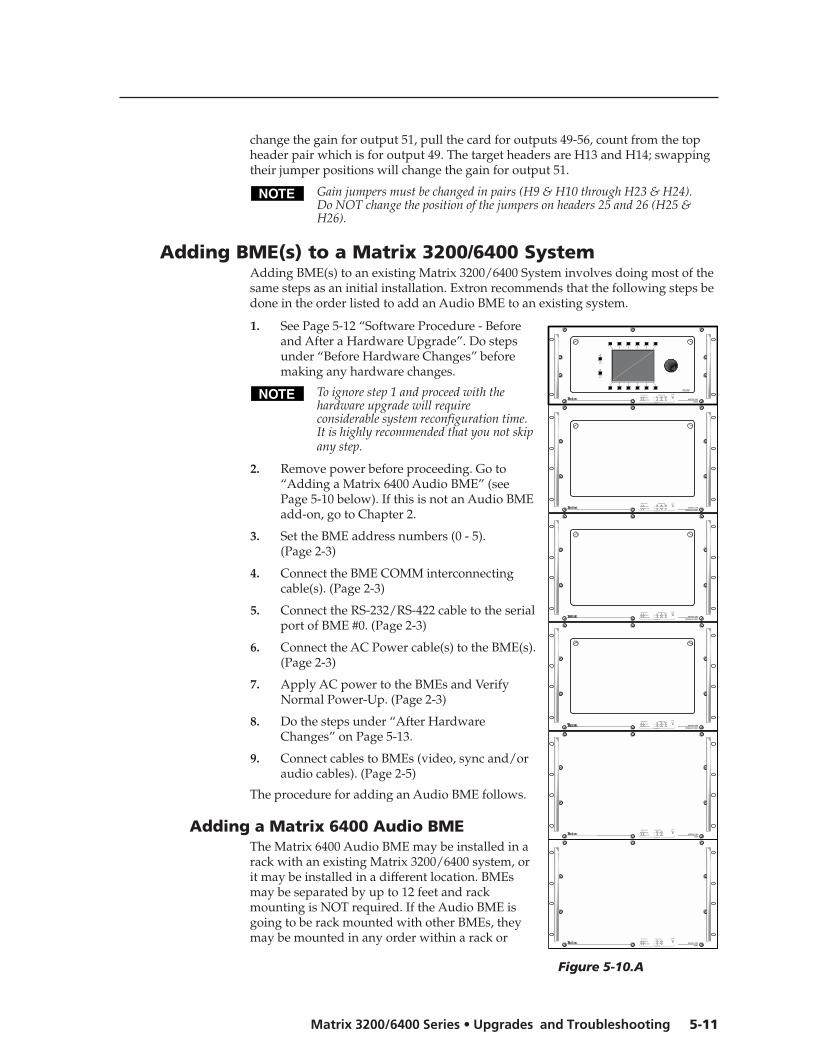
5-11Matrix 3200/6400 Series • Upgrades and Troubleshooting
change the gain for output 51, pull the card for outputs 49-56, count from the topheader pair which is for output 49. The target headers are H13 and H14; swappingtheir jumper positions will change the gain for output 51.
Gain jumpers must be changed in pairs (H9 & H10 through H23 & H24).Do NOT change the position of the jumpers on headers 25 and 26 (H25 &H26).
Adding BME(s) to a Matrix 3200/6400 SystemAdding BME(s) to an existing Matrix 3200/6400 System involves doing most of thesame steps as an initial installation. Extron recommends that the following steps bedone in the order listed to add an Audio BME to an existing system.
1. See Page 5-12 “Software Procedure - Beforeand After a Hardware Upgrade”. Do stepsunder “Before Hardware Changes” beforemaking any hardware changes.
To ignore step 1 and proceed with thehardware upgrade will requireconsiderable system reconfiguration time.It is highly recommended that you not skipany step.
2. Remove power before proceeding. Go to“Adding a Matrix 6400 Audio BME” (seePage 5-10 below). If this is not an Audio BMEadd-on, go to Chapter 2.
3. Set the BME address numbers (0 - 5).(Page 2-3)
4. Connect the BME COMM interconnectingcable(s). (Page 2-3)
5. Connect the RS-232/RS-422 cable to the serialport of BME #0. (Page 2-3)
6. Connect the AC Power cable(s) to the BME(s).(Page 2-3)
7. Apply AC power to the BMEs and VerifyNormal Power-Up. (Page 2-3)
8. Do the steps under “After HardwareChanges” on Page 5-13.
9. Connect cables to BMEs (video, sync and/oraudio cables). (Page 2-5)
The procedure for adding an Audio BME follows.
Adding a Matrix 6400 Audio BMEThe Matrix 6400 Audio BME may be installed in arack with an existing Matrix 3200/6400 system, orit may be installed in a different location. BMEsmay be separated by up to 12 feet and rackmounting is NOT required. If the Audio BME isgoing to be rack mounted with other BMEs, theymay be mounted in any order within a rack or
MATRIX 6400
WIDEBAND VIDEO
MATRIX 6400
WIDEBAND VIDEO
MATRIX 6400
WIDEBAND VIDEO
MATRIX 6400
SYNC
MATRIX 6400
SYNC
MATRIX 6400
AUDIO
POWER SUPPLIES COMMUNICATIONS
PRIMARY TX
RS232 BME REMOTE
SYSTEM
STATUS
REDUNDANT RX
DIAGNOSTICS
+V -V
POWER SUPPLIES COMMUNICATIONS
PRIMARY TX
RS232 BME REMOTE
SYSTEM
STATUS
REDUNDANT RX
DIAGNOSTICS
+V -V
POWER SUPPLIES COMMUNICATIONS
PRIMARY TX
RS232 BME REMOTE
SYSTEM
STATUS
REDUNDANT RX
DIAGNOSTICS
+V -V
POWER SUPPLIES COMMUNICATIONS
PRIMARY TX
RS232 BME
SYSTEM
STATUS
REDUNDANT RX
DIAGNOSTICS
+V -V
POWER SUPPLIES COMMUNICATIONS
PRIMARY TX
RS232 BME
SYSTEM
STATUS
REDUNDANT RX
DIAGNOSTICS
+V -V
POWER SUPPLIES COMMUNICATIONS
PRIMARY TX
RS232 BME REMOTE
SYSTEM
STATUS
REDUNDANT RX
DIAGNOSTICS
+V -V
FPC-1000
RGB
MUTE
AUDIO
MUTE
Figure 5-10.A
Upgrades and Troubleshooting, cont’d
Matrix 3200/6400 Series • Upgrades and Troubleshooting5-12
cabinet. There are no restrictions to the order in which BMEs may be mountedrelative to each other. Logically, the BME addresses in a system such as the oneshown in Figure 5-10.A would be set to 0 - 5 sequentially from top to bottom,however, a different order is acceptable and will not impact system operation inany way.
Equipment location within a room should be given careful consideration. Poorplanning, with the number of cables involved, could result in a clutteredappearance. Power requirements andthe amount of heat exhaust from the system should be taken into consideration.
The following restrictions apply to installing BMEs.
• One BME must be assigned as BME#0.
• A BME with an FPC must be BME#0
• Address assignments must not skip numbers.
• Address assignments of 0 - 5 are accepted, BMEs w/address 6-9 are ignored.
• A system is limited to one audio module.
See Page 2-2 for other BME restrictions.
Go to step 3 above.
Software Procedure – Before and After a HardwareUpgrade
Prior to upgrading a Matrix 3200/6400 Wideband Video Switcher System, read the“Upgrade System – Software Procedure” below. The suggested procedure can saveyou a lot of time reconfiguring a system that is going to have a hardware upgradeinstalled. The procedure includes steps to be performed before and after thehardware upgrade.
Upgrade System – Software ProcedureThe UPGRADE WIZARD is started by clicking the TOOLS | UPGRADE menu onthe main screen. It guides you through restoration of all your system settings(programming of Presets, Virtual Names, Rooms, etc.) when you add more physicalIO ports or more BMEs to your existing 3200/6400 system.
The following procedures must be done in the sequence listed to save the originalsystem settings and use them to create a new configuration.
Before Hardware ChangesDo the following steps BEFORE starting the hardware upgrade:
1. From Windows open the “Extron Electronics” program group or folder.
2. Double click the “Matrix 6400 Control Pgm” icon to start the program. Youwill be asked to select the COMM port, or choose “Emulate” mode. After theCOMM port is selected, the software looks for the matrix system, “reads” itsconfiguration, and then displays it in a window called “Extron’s Matrix 6400Control Program.
3. Click on TOOLS, the TOOLS menu is displayed. Click on Upgrade.
4. The “Upgrade Wizard” dialog box shown below will be displayed. Theoptions are Yes, No, and Cancel. Click on ”No” (since the hardware changeshave NOT been installed at this point).

5-13Matrix 3200/6400 Series • Upgrades and Troubleshooting
• The current MATRIX settings will be saved in the MTRX6400.INI file.
• The Matrix 6400 Control Pgm will shut down to allow you to power downthe system to make the hardware changes.
5. Return to step 2 of the applicable procedure (Page 5-8 or 5-11).
Note: The “After Hardware Changes” procedure begins on Page 5-13.
After Hardware ChangesDo the following steps AFTER the hardware upgrade has been installed:
1. From Windows open the Program Group or Folder called “Extron Electronics”.
2. Double click the “Matrix 6400 Control Pgm” icon to start the program. Youwill be asked to select the COMM port, or choose “Emulate” mode. After theCOMM port is selected, the software looks for the matrix system, “reads” itsconfiguration, and then displays it in a window called “Extron’s Matrix 6400Control Program.
3. Click on TOOLS, the TOOLS menu is displayed. Click on Upgrade.
4. The “Upgrade Wizard” dialog box shown below will be displayed. Theoptions are Yes, NO and Cancel. Click on ”Yes” (since the hardware changeshave been installed at this point). The “Upgrade Wizard” does the following:
• Presents the Virtual Configuration screen so you may re-virtualize thesystem to match your new hardware configuration.
• Restores MATRIX settings from the MTRX6400.INI file saved before thehardware configuration was changed. All settings are restored frombefore, except the Map.
• You may want to assign new icons and names to any Virtual IO portsthat were newly created by your upgrade after the wizard has finished.This would also be the time to update your Room Configurations ifneeded.
5. Verify that the system (including the new hardware) is functioning correctly. Ifthe system is not functioning as expected, call Extron Technical Support.
The upgrade wizard also allows you to downgrade your system (removehardware), but various Room and Preset settings may not fully restore sincesome of the Virtual input and output ports may no longer exist.

Upgrades and Troubleshooting, cont’d
Matrix 3200/6400 Series • Upgrades and Troubleshooting5-14
Notes
Matrix 6400 Audio Switcher
AAppendix A
Reference Information
Switcher Part Numbers
Related Part Numbers
BNC Cables
Glossary of Terms

Reference Information, cont’d
Matrix 3200/6400 Series • Reference InformationA-2
Reference Information
Matrix 3200/6400 Series Part NumbersPart Numbers for Matrix 3200/6400 switchers use the following format:
60-25x-iofr
where: x = 0 = Matrix 6400 Widebandx = 1 = Matrix 3200 Widebandx = 2 = Matrix 6400 Videox = 3 = Matrix 3200 Videox = 4 = Matrix 6400 Syncx = 5 = Matrix 3200 Syncx = 6 = Matrix 6400 Audio
io = Inputs/Outputs (Matrix size). The i and the o are replacedby two characters which identify the exact size of the Matrix.
f = Front Panel Controller (FPC-1000)f = 0 = No, f = 1 = Yes
r = Redundant Power Supplyr = 0 = No, r = 1 = Yes
An example of a typical Matrix 3200/6400 part number is: 60-250-HD11
In this example: x = 0 = Matrix 6400 Wideband
io = HD = 64x32 which was obtained from the Matrix 6400Wideband Part Number Table on Page A-3 as illustrated below.The vertical column identifies i (# of Inputs) and the horizontalrow identifies o (# of Outputs).
f = 1 = yes = Front Panel Controllerr = 1 = yes = Redundant Power Supply
For the example above, the io characters would be BA for matrix size 32x8, DD formatrix size 32x32 and PH for matrix size 64x64.
The Matrix 3200 Wideband and Matrix 6400 Audio io characters are selected usingthe same procedure as is used with the Matrix 6400 Wideband, but with differenttables as shown on Page A-3.
The io characters for the Matrix 3200 Sync part number are DD as it is onlyavailable in one matrix size, 32x32. The io characters for the Matrix 6400 Sync partnumbers are PH as it is also available in only one matrix size, 64x64. Either of thetwo Sync part numbers may include r = 0 or 1 but f must be 0 as a Sync modulecannot have a Front Panel Controller.
Matrix 3200/6400 Part Numbers (with matrix tables) are shown on Page A-3.
AAABBCBDCECFDGDH
BABBDCDDFEFFHGHH
CACBFCFD
LGLH
DADBHCHDLELFPGPH
16 32 48 648
16243240485664

A-3Matrix 3200/6400 Series • Reference Information
Matrix 3200/6400 Series Part Numbers (continued from previouspage)
Extron Part Part #Matrix 6400 Wideband Switcher 60-250-iofr
Two io (Inputs/Outputs) characters = table matrix size coordinate points.
f = Front Panel Controller (FPC), 0 = No, 1 = Yes
r = Redundant Power Supply (RPS), 0 = No, 1 = Yes
Examples:60-250-IE11 = 48 Inputs/40 Outputs 1-FPC & 1- RPS60-250-HD10 = 64 Inputs/32 Outputs 1-FPC & 0-RPS60-250-PH00 = 64 Inputs/64 Outputs 0-FPC & 0-RPS
Matrix 3200 Wideband Switcher 60-251-iofrTwo io (Inputs/Outputs) characters = table matrix size coordinate points.
f = Front Panel Controller (FPC), 0 = No, 1 = Yes
r = Redundant Power Supply (RPS), 0 = No, 1 = Yes
Examples: 60-251-BB01 = 32 Inputs/16 Outputs 0-FPC & 1- RPS 60-251-DC10 = 32 Inputs/24 Outputs 1-FPC & 0-RPS 60-251-DD11 = 32 Inputs/32 Outputs 1-FPC & 1-RPS
Matrix 6400 Video Switcher 60-252-iofrTwo io (Inputs/Outputs) characters = table matrix size coordinate points.
f = Front Panel Controller (FPC), 0 = No, 1 = Yes
r = Redundant Power Supply (RPS), 0 = No, 1 = Yes
Examples:
60-252-HE11 = 64 Inputs/40 Outputs 1-FPC & 1- RPS60-252-HD10 = 64 Inputs/32 Outputs 1-FPC & 0-RPS60-252-HH00 = 64 Inputs/64 Outputs 0-FPC & 0-RPS
Matrix 3200 Video Switcher 60-253-iofrTwo io (Inputs/Outputs) characters = table matrix size coordinate points.
f = Front Panel Controller (FPC), 0 = No, 1 = Yes
r = Redundant Power Supply (RPS), 0 = No, 1 = Yes
Examples: 60-253-DB01 = 32 Inputs/16 Outputs 0-FPC & 1- RPS 60-253-DC10 = 32 Inputs/24 Outputs 1-FPC & 0-RPS 60-253-DD11 = 32 Inputs/32 Outputs 1-FPC & 1-RPS
Matrix 6400 Sync Switcher 60-254-PH0rr = Redundant Power Supply (RPS), 0 = No, 1 = Yes
Examples: 60-254-PH01 = 64 Inputs/64 Outputs with RPS
60-254-PH00 = 64 Inputs/64 Outputs without RPS
Matrix 3200 Sync Switcher 60-255-DD0rr = Redundant Power Supply (RPS), 0 = No, 1 = Yes
Examples: 60-255-DD01 = 32 Inputs/32 Outputs with RPS
60-255-DD00 = 32 Inputs/32 Outputs without RPS
Matrix 6400 Audio Switcher (Stereo or Mono*) 60-256*-iofrTwo io (Inputs/Outputs) characters = table matrix size coordinate points.
f = Front Panel Controller (FPC), 0 = No, 1 = Yes
r = Redundant Power Supply (RPS), 0 = No, 1 = Yes
Examples:
60-256*-HD01 = 64 Inputs/32 Outputs with RPS (no FPC)
60-256*-HH10 = 64 Inputs/64 Outputs with FPC (no RPS)
60-256*-DB11 = 32 Inputs/16 Outputs with FPC & RPS
60-256*-BA00 = 16 Inputs/8 Outputs (no FPC, no RPS)
* Part numbers shown are for Stereo models. For Mono Audio Model part numbers,
replace 60-256 with 60-529.
AAABACADAEAFAGAH
BABBBCBDBEBFBGBH
CACBCCCDCECFCGCH
DADBDCDDDEDFDGDH
16 32 48 648
16243240485664
EAEBECEDEEEFEGEH
FAFBFCFDFEFFFGFH
GAGBGCGDGEGFGGGH
HAHBHCHDHEHFHGHH
5640248
AAABBCBDCECFDGDH
BABBDCDDFEFFHGHH
CA CBFCFDIEIFLGLH
DADBHCHDLELFPGPH
16 32 48 648
16243240485664
AAABBCBD
16 328
162432
BABBDCDD
HAHBHCHDHEHFHGHH
81624
3240
48
5664
64
DADBDCDD
328
16
24
32
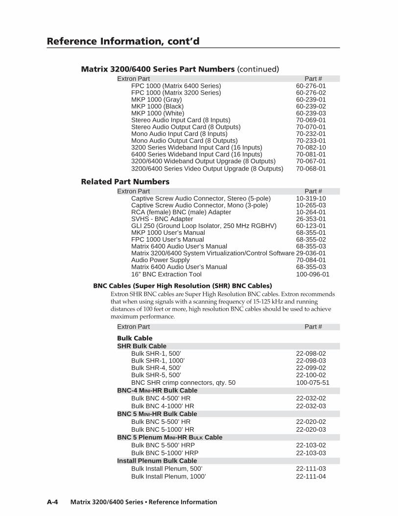
Reference Information, cont’d
Matrix 3200/6400 Series • Reference InformationA-4
Matrix 3200/6400 Series Part Numbers (continued)Extron Part Part #
FPC 1000 (Matrix 6400 Series) 60-276-01FPC 1000 (Matrix 3200 Series) 60-276-02MKP 1000 (Gray) 60-239-01MKP 1000 (Black) 60-239-02MKP 1000 (White) 60-239-03Stereo Audio Input Card (8 Inputs) 70-069-01Stereo Audio Output Card (8 Outputs) 70-070-01Mono Audio Input Card (8 Inputs) 70-232-01Mono Audio Output Card (8 Outputs) 70-233-013200 Series Wideband Input Card (16 Inputs) 70-082-106400 Series Wideband Input Card (16 Inputs) 70-081-013200/6400 Wideband Output Upgrade (8 Outputs) 70-067-013200/6400 Series Video Output Upgrade (8 Outputs) 70-068-01
Related Part NumbersExtron Part Part #
Captive Screw Audio Connector, Stereo (5-pole) 10-319-10Captive Screw Audio Connector, Mono (3-pole) 10-265-03RCA (female) BNC (male) Adapter 10-264-01SVHS - BNC Adapter 26-353-01GLI 250 (Ground Loop Isolator, 250 MHz RGBHV) 60-123-01MKP 1000 User’s Manual 68-355-01FPC 1000 User’s Manual 68-355-02Matrix 6400 Audio User’s Manual 68-355-03Matrix 3200/6400 System Virtualization/Control Software 29-036-01Audio Power Supply 70-084-01Matrix 6400 Audio User’s Manual 68-355-0316” BNC Extraction Tool 100-096-01
BNC Cables (Super High Resolution (SHR) BNC Cables)Extron SHR BNC cables are Super High Resolution BNC cables. Extron recommendsthat when using signals with a scanning frequency of 15-125 kHz and runningdistances of 100 feet or more, high resolution BNC cables should be used to achievemaximum performance.
Extron Part Part #
Bulk CableSHR Bulk Cable
Bulk SHR-1, 500’ 22-098-02Bulk SHR-1, 1000’ 22-098-03Bulk SHR-4, 500’ 22-099-02Bulk SHR-5, 500’ 22-100-02BNC SHR crimp connectors, qty. 50 100-075-51
BNC-4 MINI-HR Bulk CableBulk BNC 4-500’ HR 22-032-02Bulk BNC 4-1000’ HR 22-032-03
BNC 5 MINI-HR Bulk CableBulk BNC 5-500’ HR 22-020-02Bulk BNC 5-1000’ HR 22-020-03
BNC 5 Plenum MINI-HR BULK CableBulk BNC 5-500’ HRP 22-103-02Bulk BNC 5-1000’ HRP 22-103-03
Install Plenum Bulk CableBulk Install Plenum, 500’ 22-111-03Bulk Install Plenum, 1000’ 22-111-04
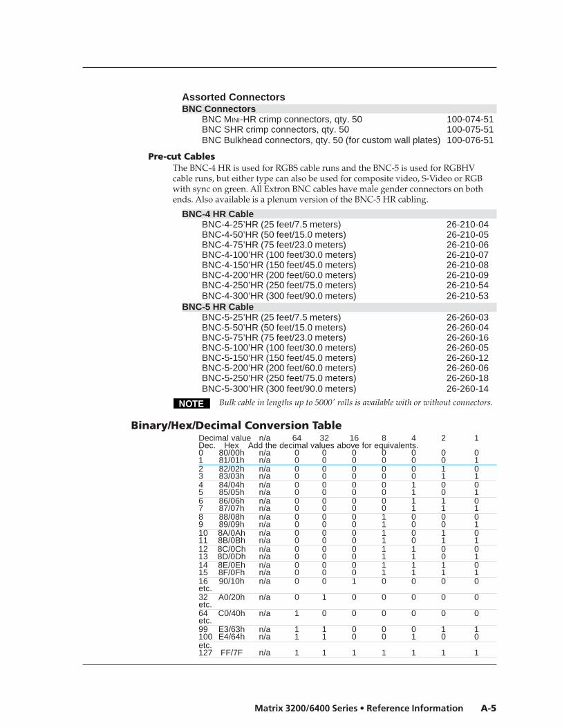
A-5Matrix 3200/6400 Series • Reference Information
Assorted ConnectorsBNC Connectors
BNC MINI-HR crimp connectors, qty. 50 100-074-51BNC SHR crimp connectors, qty. 50 100-075-51BNC Bulkhead connectors, qty. 50 (for custom wall plates) 100-076-51
Pre-cut CablesThe BNC-4 HR is used for RGBS cable runs and the BNC-5 is used for RGBHVcable runs, but either type can also be used for composite video, S-Video or RGBwith sync on green. All Extron BNC cables have male gender connectors on bothends. Also available is a plenum version of the BNC-5 HR cabling.
BNC-4 HR CableBNC-4-25’HR (25 feet/7.5 meters) 26-210-04BNC-4-50’HR (50 feet/15.0 meters) 26-210-05BNC-4-75’HR (75 feet/23.0 meters) 26-210-06BNC-4-100’HR (100 feet/30.0 meters) 26-210-07BNC-4-150’HR (150 feet/45.0 meters) 26-210-08BNC-4-200’HR (200 feet/60.0 meters) 26-210-09BNC-4-250’HR (250 feet/75.0 meters) 26-210-54BNC-4-300’HR (300 feet/90.0 meters) 26-210-53
BNC-5 HR CableBNC-5-25’HR (25 feet/7.5 meters) 26-260-03BNC-5-50’HR (50 feet/15.0 meters) 26-260-04BNC-5-75’HR (75 feet/23.0 meters) 26-260-16BNC-5-100’HR (100 feet/30.0 meters) 26-260-05BNC-5-150’HR (150 feet/45.0 meters) 26-260-12BNC-5-200’HR (200 feet/60.0 meters) 26-260-06BNC-5-250’HR (250 feet/75.0 meters) 26-260-18BNC-5-300’HR (300 feet/90.0 meters) 26-260-14
Bulk cable in lengths up to 5000' rolls is available with or without connectors.
Binary/Hex/Decimal Conversion TableDecimal value n/a 64 32 16 8 4 2 1Dec. Hex Add the decimal values above for equivalents.0 80/00h n/a 0 0 0 0 0 0 01 81/01h n/a 0 0 0 0 0 0 12 82/02h n/a 0 0 0 0 0 1 03 83/03h n/a 0 0 0 0 0 1 14 84/04h n/a 0 0 0 0 1 0 05 85/05h n/a 0 0 0 0 1 0 16 86/06h n/a 0 0 0 0 1 1 07 87/07h n/a 0 0 0 0 1 1 18 88/08h n/a 0 0 0 1 0 0 09 89/09h n/a 0 0 0 1 0 0 110 8A/0Ah n/a 0 0 0 1 0 1 011 8B/0Bh n/a 0 0 0 1 0 1 112 8C/0Ch n/a 0 0 0 1 1 0 013 8D/0Dh n/a 0 0 0 1 1 0 114 8E/0Eh n/a 0 0 0 1 1 1 015 8F/0Fh n/a 0 0 0 1 1 1 116 90/10h n/a 0 0 1 0 0 0 0etc.32 A0/20h n/a 0 1 0 0 0 0 0etc.64 C0/40h n/a 1 0 0 0 0 0 0etc.99 E3/63h n/a 1 1 0 0 0 1 1100 E4/64h n/a 1 1 0 0 1 0 0etc.127 FF/7F n/a 1 1 1 1 1 1 1

Reference Information, cont’d
Matrix 3200/6400 Series • Reference InformationA-6
Glossary of termsFollowing is a list of terms taken from Extron’s Glossary.
AC – Alternating Current – Flow of electrons that changes direction alternately.
ADA – Extron’s product designation for Analog Distribution Amplifier.
AMPS – Amperes – A unit of measurement for current.
Analog – Analogue – A continuous signal that takes time to make a transitionfrom one level to another. Standard audio and video signals are analog. Thissignal has an infinite number of levels between its highest and lowest value.(Not represented by bits, such as with digital.)
ANSI – American National Standards Institute
ASCII – American Standard Code for Information Interchange – The standardcode consisting of 7-bit coded characters (8 bits including parity check),utilized to exchange information between data processing systems, datacommunication systems, and associated equipment. The ASCII set containscontrol characters and graphic characters.
Attenuation – The decrease in magnitude of a signal.
Audio Follow – A term used when audio is tied to other signals, such as video,and they are switched together. (The opposite of Break-away)
Balanced Audio – A method that uses three conductors for one audio signal.They are plus (+), minus (-) and ground. The ground conductor is strictly forshielding, and does not carry any signal. Also Differential Audio.
Bandwidth – A frequency range, or “band” of frequencies, within which a deviceoperates. In audio and video, it is the band of frequencies that can passthrough a device without significant loss or distortion. The higher thebandwidth, the sharper the picture; low bandwidth can cause a “fuzzy”picture.
Barrel – Outward curved edges on a display image. Also see “pincushion”.
Blanking – The turning off of the electron beam that scans the image onto thescreen. When the beam completes a scan line it must return (retrace) backto the left. During this time, the beam must be turned off (horizontalblanking). Similarly, when the last line has been scanned at the bottom of thescreen, the beam must return to the upper left. This requires verticalblanking.
Blooming – Most noticeable at the edges of images on a CRT, “blooming” iswhen the light (color) is so intense that it seems to exceed the boundary ofthe object. Thin lines and sharp edges could look thick and fuzzy. This maybe caused by the brightness being set to high, or by a high voltage problem.
BNC – It is a cylindrical Bayonet Connector which operates with a twist-lockingmotion. Two curved grooves in the collar of the male connector are alignedwith two projections on the outside of the female collar. This allows theconnector to be locked in place without the need of tools.
Break-away – The ability to separate signals for the purpose of switching themindependently. For example: an audio and video signal from the samesource may be “broken away” and switched to different destinations. This isthe opposite of the term “follow”.
Buffer – Generally referred to as a unity gain amplifier used to isolate the signalsource from the load. This is for both digital and analog signals.
Cable Equalization – The method of altering the frequency response of a videoamplifier to compensate for high frequency losses in cables that it feeds.(See Peaking.)
Capacitance – The storing of an electrical charge. At high frequencies,capacitance that exists in cables also represents a form of impedance.
Cathode Ray Tube – See CRT.
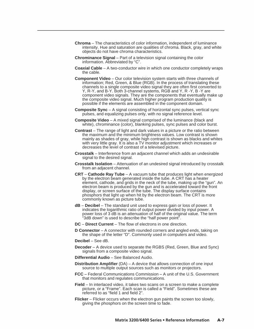
A-7Matrix 3200/6400 Series • Reference Information
Chroma – The characteristics of color information, independent of luminanceintensity. Hue and saturation are qualities of chroma. Black, gray, and whiteobjects do not have chroma characteristics.
Chrominance Signal – Part of a television signal containing the colorinformation. Abbreviated by “C”.
Coaxial Cable – A two-conductor wire in which one conductor completely wrapsthe cable.
Component Video – Our color television system starts with three channels ofinformation; Red, Green, & Blue (RGB). In the process of translating thesechannels to a single composite video signal they are often first converted toY, R-Y, and B-Y. Both 3-channel systems, RGB and Y, R -Y, B -Y arecomponent video signals. They are the components that eventually make upthe composite video signal. Much higher program production quality ispossible if the elements are assembled in the component domain.
Composite Sync – A signal consisting of horizontal sync pulses, vertical syncpulses, and equalizing pulses only, with no signal reference level.
Composite Video – A mixed signal comprised of the luminance (black andwhite), chrominance (color), blanking pulses, sync pulses and color burst.
Contrast – The range of light and dark values in a picture or the ratio betweenthe maximum and the minimum brightness values. Low contrast is shownmainly as shades of gray, while high contrast is shown as blacks and whiteswith very little gray. It is also a TV monitor adjustment which increases ordecreases the level of contrast of a televised picture.
Crosstalk – Interference from an adjacent channel which adds an undesirablesignal to the desired signal.
Crosstalk Isolation – Attenuation of an undesired signal introduced by crosstalkfrom an adjacent channel.
CRT – Cathode Ray Tube – A vacuum tube that produces light when energizedby the electron beam generated inside the tube. A CRT has a heaterelement, cathode, and grids in the neck of the tube, making up the “gun”. Anelectron beam is produced by the gun and is accelerated toward the frontdisplay, or screen surface of the tube. The display surface containsphosphors that light up when hit by the electron beam. The CRT is morecommonly known as picture tube.
dB – Decibel – The standard unit used to express gain or loss of power. Itindicates the logarithmic ratio of output power divided by input power. Apower loss of 3 dB is an attenuation of half of the original value. The term“3dB down” is used to describe the “half power point”.
DC – Direct Current – The flow of electrons in one direction.
D Connector – A connector with rounded corners and angled ends, taking onthe shape of the letter “D”. Commonly used in computers and video.
Decibel – See dB.
Decoder – A device used to separate the RGBS (Red, Green, Blue and Sync)signals from a composite video signal.
Differential Audio – See Balanced Audio.
Distribution Amplifier (DA) – A device that allows connection of one inputsource to multiple output sources such as monitors or projectors.
FCC – Federal Communications Commission – A unit of the U.S. Governmentthat monitors and regulates communications.
Field – In interlaced video, it takes two scans on a screen to make a completepicture, or a “Frame”. Each scan is called a “Field”. Sometimes these arereferred to as “field 1 and field 2”.
Flicker – Flicker occurs when the electron gun paints the screen too slowly,giving the phosphors on the screen time to fade.

Reference Information, cont’d
Matrix 3200/6400 Series • Reference InformationA-8
Frame – In interlaced video, a Frame is one complete picture. A Frame is madeup of two fields, or two sets of interlaced lines.
Frequency Range – Refers to the low-to-high limits of a device, such as acomputer, projector or monitor. Also “bandwidth”.
Gain – A general term used to denote an increase in signal power or voltageproduced by an amplifier in transmitting a signal from one point to another.The amount of gain is usually expressed in decibels above a reference level.Opposite of Attenuation.
Genlock – A method of synchronizing video equipment by using a common,external “Genlock” signal.
Hertz – Hz – A measure of frequency in cycles per second.
High Impedance – Hi Z or High Z – In video, when the signal is not terminatedlocally and is going to another destination, where it will be terminated. Invideo, Hi Z is typically 10k ohms or greater.
Horizontal Rate – Horizontal Frequency – The number of complete horizontallines, including trace and retrace, scanned per second. Typically shown as ameasure of kHz.
Horizontal Resolution – Smallest increment of a television picture that can bediscerned in the horizontal plane. This increment is dependent upon thevideo bandwidth and is measured in frequency. Determines the number oflines it takes to scan an image on the screen.
Hue – Tint Control – Red, yellow, blue, etc. are hues of color or types of color.Hue is the parameter of color that allows us to distinguish between colors.
Hz – Hertz – Frequency in cycles per second.
Impedance – Z – The opposition or “load” to a signal. Circuits that generateaudio or video signals, are designed to work with a certain “load”, orimpedance. Typical video impedances: 75 ohm or High Z. Also see HighImpedance and Low Impedance.
Interlaced – The process of scanning whereby the alternate lines of bothscanned fields fall evenly between each other.
IRE Scale – An oscilloscope scale that applies to composite video levels.Typically there are 140 IRE units in one volt (1 IRE = 7.14 mV).
K – An abbreviation for kilobyte. A kilobyte is 1,000 bytes. In computer memorysizes, the numbers are rounded down. e.g. 1k byte = 1024 bytes.
Kilohertz – kHz – Thousands of Hertz, or a frequency rate in units of thousandsof cycles per second. For example, CGA’s horizontal scan rate is 15.75 kHzor 15,750 hertz (Hz).
LED – Light-Emitting Diode
Level Control – The Level Control on selected Extron interface products issimilar to the Contrast Control on a data monitor. It can either increase ordecrease the output voltage level of the interface to the connected datamonitor or projector. This results in greater or less contrast in the picture.
Low Impedance – The condition where the source or load is at a lowerimpedance than the characteristic impedance of the cable. Low sourceimpedances are common; low load impedances are usually fault conditions.
Luminance – This is the signal that represents brightness in a video picture.Luminance is any value between black and white. In mathematicalequations, luminance is abbreviated as “Y”.
M – Mega – An abbreviation for megabyte. A megabyte is 1024K, or roughly amillion bytes (1,048,076 to be exact [1024 x 1024]).
Matrix – In A/V, an electronic device used to collect and distribute video (andsometimes audio) signals. See matrix switcher.

A-9Matrix 3200/6400 Series • Reference Information
Matrix switcher – In audio/video, a means of selecting an input source andconnecting it to one or more outputs. A Matrix switcher would normally havemultiple inputs and multiple outputs.
MHz (as in 8 MHz) – An abbreviation for megahertz. This is a unit ofmeasurement and refers to a million cycles per second. Bandwidth ismeasured in megahertz.
Milli – m – Abbreviation for one thousandth. Example: 1 ms = 1/1000 second.
Monitor – (A) A TV that may receive its signal directly from a VCR, camera orseparate TV tuner for high quality picture reproduction. It may not contain achannel selector. (B) A video display designed for use with closed circuit TVequipment. (C) Device used to display computer text and graphics.
Non-Interlaced – Also called progressive scan – a method by which all the videoscan lines are presented on the screen in one sweep instead of two (alsosee interlaced).
Nonvolatile memory – Memory that retains data when power is turned off.
NTSC – National Television Standards Committee – Television standard forNorth America and certain countries in South America. 525 lines/60 Hz (60Hz Refresh).
Output – The product of an operation by a device going to some externaldestination, such as another device, a video screen, image or hard copy.
PAL – Phase Alternate Line – The phase of the color carrier is alternated fromline to line. It takes four full pictures for the color horizontal phaserelationship to return to the reference point. This alternation helps cancel outphase errors, the reason the hue control is not needed on PAL TV sets. PAL,in its many forms is used extensively in Western Europe.
PCB – Printed Circuit Board
Peak-to-Peak – abbreviated p-p – The amplitude (voltage) difference (asdisplayed on an oscilloscope) between the most positive and the mostnegative excursions (peaks) of an electrical signal.
Peaking – A means of compensating for mid and high frequency RGB VideoBandwidth response in data monitors and projectors and for signal lossesdue to cable capacitance. When using the Peak enhancements, use thefollowing guidelines for proper output settings: Use 50% with all computerfrequencies between 15-125 kHz at any cable length. Use 100% with highfrequency computers of 36 kHz or higher with cable lengths 75 feet orgreater.
Pincushion – The inward or outward (curved) appearance of the edges of adisplay.
Pin-out – An illustration or table that names signals, voltages, etc. that are oneach pin of a connector or cable.
Plenum Cable – Cable having a covering that meets the UL specifications forresistance to fire.
PLUGE – Picture Line Up Generation Equipment – This is a name of a testpattern that assists in properly setting picture black level. PLUGE can be partof many test patterns. The phrase and origination of the test signal are bothcredited to the BBC.
Power – Electrical – The dissipation of heat by passing a current through aresistance. Measured in Watts (W), it is expressed by Ohm’s law from thetwo variables: Voltage (E) and Current (I). i.e. P = I2xR, or, P = E2/R or P =ExI
Resolution – The density of lines or dots that make up an image. Resolutiondetermines the detail and quality in the image.A) A measure of the ability of a camera or television system to reproducedetail.B) In video, generally called horizontal resolution. It can be evaluated by
Reference Information, cont’d
Matrix 3200/6400 Series • Reference InformationA-10
establishing the limit to which lines can be distinguished on a test pattern. Alarger resolution value means a broader frequency band of the video signal.C) A measure of the greatest amount of detail that can be seen in an image.Often incorrectly expressed as a number of pixels in a given line; morecorrectly it is the bandwidth.
RGB – Red, Green, Blue – The basic components of the color televisionsystem. They are also the primary colors of light, not to be confused withCyan, Magenta, and Yellow, the primary pigments. Also called the “AdditiveColor Process”.
RGB Video – A form of color video signal (red, green, blue) distinctly differentfrom the composite color video used in standard television sets. RGB can bedisplayed only on a color monitor that has a separate electron gun for eachof these primary colors. Some color television sets use only one gun. RGBmonitors are noted for their crisp, bright colors and high resolution.
RS-170A – EIA technical standard NTSC color TV.
RS-232 – An Electronic Industries Association (EIA) serial digital interfacestandard specifying the electrical and mechanical characteristics of thecommunication path between two devices using D-type connectors. Thisstandard is used for relatively short range communications and does notspecify balanced control lines.
RS-422 – An EIA serial digital interface standard which specifies the electricalcharacteristics of balanced voltage digital interface circuits. This standard isusable over longer distances than RS-232. Although originally designed foruse with 9-pin and 37-pin, D-type connectors, it is often used with others,including 25-pin D-types. It is also used as the serial port standard forMacintosh computers. This signal governs the asynchronous transmission ofcomputer data at speeds of up to 920,000 bits per second.
SECAM – Sequential Couleur Avec Memoiré – Translated as “SequentialColor with Memory”. A composite color transmission system that potentiallyeliminates the need for both a color and hue control on the monitor. One ofthe color difference signals is transmitted on one line and the second istransmitted on the second line. Memory is required to obtain both colordifference signals for color decoding. This system is used in France, Africa,Asia and many Eastern European countries.
Serial Port – An output on the computer that allows it to communicate with otherdevices in a serial fashion – data bits flowing on a single pair of wires. Theserial port is most often used with RS-232 protocol.
SMPTE – Society of Motion Picture and Television Engineers – A globalorganization, based in the United States, that sets standards for base-bandvisual communications. This includes film as well as video standards.
SMPTE Pattern – The video test pattern made up of color, black, and whitebands used by television stations.
Software – The programs used to instruct a processor and its peripheralequipment.
Switcher – Term often used to describe a special effects generator; a unit whichallows the operator to switch between video camera signals. Switchers areoften used in industrial applications to switch between video cameramonitoring certain areas for display on a monitor, or system of displaydevices. These kinds of switchers do not have sync generators.
Sync – In video, a means of synchronizing signals with timing pulses to insurethat each step in a process occurs at exactly the right time. For example:Horizontal Sync determines exactly when to begin each horizontal line(sweep) of the electron beam. Vertical Sync determines when to bring theelectron beam to the top-left of the screen to start a new field. There aremany other types of sync in a video system. (Also called Sync Signal orSync Pulse.)

A-11Matrix 3200/6400 Series • Reference Information
SVHS – A high band video recording process for VHS that increases the picturequality and resolution capability. See S-Video.
S-Video – The composite video signal is separated into the Luminance (Y) andthe Chrominance (C).
Terminal – A device typically having a keyboard and display that is capable ofsending text to and receiving text from another device, a network, etc.
Termination – A load, or impedance at the end of a cable or signal line used tomatch the impedance of the equipment that generated the signal. Theimpedance absorbs signal energy to prevent signal reflections from goingback toward the source. In the video industry, termination impedance istypically 75 ohms.
Vertical Interval – The synchronizing information which is presented betweenfields, and then signals the picture monitor to return to the top of the screento start another vertical scan.
Videoconferencing — Conducting a conference between two or more locationsusing video cameras, microphones and video monitors. The participants canbe seen, as well as heard. Referred to as a “virtual conference room”.
Virtual conference room — See videoconferencing.
Virtual map — Used with Extron’s virtual matrix switchers (Matrix 3200/6400), avirtual map is made up of tables stored in memory that relate physicalconnectors (as on the back panel) to logical connections (as seen by theuser). In printed form, this can show physical input/output connectornumbers as they relate to virtual input/output numbers.
Virtual memory — The process of increasing the apparent size of a computer’srandom-access memory (RAM) by using a section of the hard disk storageas an extension of RAM.
Virtual switching — A means of making real, physical input or output portsappear to have different numbers. For example, Extron’s Matrix 3200/6400switchers can be programmed to switch a set (group) of connectors as one.Also see virtual map.
Wideband – A relative term indicating a high bandwidth.
Y – In video, “Y” is an abbreviation for Luminance.
Z – A symbol for impedance.

Reference Information, cont’d
Matrix 3200/6400 Series • Reference InformationA-12

FCC Class A NoticeNote: This equipment has been tested and found to comply with the limits for a Class A digitaldevice, pursuant to part 15 of the FCC Rules. These limits are designed to provide reasonableprotection against harmful interference when the equipment is operated in a commercialenvironment. This equipment generates, uses and can radiate radio frequency energy and, if notinstalled and used in accordance with the instruction manual, may cause harmful interference toradio communications. Operation of this equipment in a residential area is likely to cause harmfulinterference, in which case the user will be required to correct the interference at his own expense.
Note: This unit was tested with shielded cables on the peripheral devices. Shielded cables must beused with the unit to ensure compliance.
Extron’s WarrantyExtron Electronics warrants this product against defects in materials and workmanship for a periodof three years from the date of purchase. In the event of malfunction during the warranty periodattributable directly to faulty workmanship and/or materials, Extron Electronics will, at its option,repair or replace said products or components, to whatever extent it shall deem necessary to restoresaid product to proper operating condition, provided that it is returned within the warranty period,with proof of purchase and description of malfunction to:
USA, Canada, South America, Europe, Africa, and the Middle and Central America: East:
Extron Electronics, EuropeExtron Electronics Beeldschermweg 6C1230 South Lewis Street 3821 AH AmersfoortAnaheim, CA 92805, USA The Netherlands
Asia: Japan:
Extron Electronics, JapanExtron Electronics, Asia Daisan DMJ Bldg. 6F,135 Joo Seng Road, #04-01 3-9-1 Kudan MinamiPM Industrial Bldg. Chiyoda-ku, Tokyo 102-0074Singapore 368363 Japan
This Limited Warranty does not apply if the fault has been caused by misuse, improper handlingcare, electrical or mechanical abuse, abnormal operating conditions or non-Extron authorizedmodification to the product.
If it has been determined that the product is defective, please call Extron and ask for an ApplicationsEngineer at (714) 491-1500 (USA), 31.33.453.4040 (Europe), 65.6383.4400 (Asia), or 81.3.3511.7655 (Japan)to receive an RA# (Return Authorization number). This will begin the repair process as quickly aspossible.
Units must be returned insured, with shipping charges prepaid. If not insured, you assume the riskof loss or damage during shipment. Returned units must include the serial number and adescription of the problem, as well as the name of the person to contact in case there are anyquestions.
Extron Electronics makes no further warranties either expressed or implied with respect to theproduct and its quality, performance, merchantability, or fitness for any particular use. In no eventwill Extron Electronics be liable for direct, indirect, or consequential damages resulting from anydefect in this product even if Extron Electronics has been advised of such damage.
Please note that laws vary from state to state and country to country, and that some provisions ofthis warranty may not apply to you.

Extron Electronics, USA1230 South Lewis StreetAnaheim, CA 92805USA714.491.1500 Fax 714.491.1517
Extron Electronics, EuropeBeeldschermweg 6C3821 AH AmersfoortThe Netherlands+31.33.453.4040 Fax +31.33.453.4050
Extron Electronics, Asia135 Joo Seng Road, #04-01PM Industrial BuildingSingapore 368363+65.6383.4400 Fax +65.6383.4664
Extron Electronics, JapanDaisan DMJ Building 6F3-9-1 Kudan MinamiChiyoda-ku, Tokyo 102-0074 Japan +81.3.3511.7655 Fax +81.3.3511.7656www.extron.com
© 2002 Extron Electronics. All rights reserved.