materials services infrastructure instructions for use
TRANSCRIPT

Information about the instructions for use
These instructions enable the safe and efficient use of krings trench boxes. The instructions are part of the sys-tems and shall be kept in close proximity of the shoring site, accessible to the personnel at all times.
The personnel must read and understand these instructions thoroughly before starting to work. Prerequisite for safe work is observance of all safety precautions and work in-structions specified in these instructions.
In addition, the local occupational health and safety regu-lations and general safety regulations for the area of appli-cation apply.
All safety-related dimensions conform with German safety and accident prevention regulations and German stand-ards. The respective state-specific regulations are to be checked and applied before the works start.
Materials Services Infrastructure
Instructions for use krings trench boxes
Date: September 2020
Contents
1 System overview 2
2 Occupational safety and general information in accordance with DIN EN 13331-1/-2 5
2.1 Symbols in these instructions ............................ 5 2.2 Dangers ......................................................... 6 2.3 General safety information and measures for
reduction of risks ............................................. 6 2.4 Protection against falls and falling parts .............. 7 2.5 Storage, transportation and lifting operations ...... 7 2.6 Criteria for the inspection, repair and withdrawal
of worn or damaged components ...................... 8 2.7 The following, as amended, apply in particular: ... 9 2.8 Personal protective equipment (PPE) .................. 9 2.9 Technical data of the shoring elements ............... 9
3 Installation instructions for edge-supported shoring systems krings 10
3.1 Installation instructions krings shoring corner .... 12 3.2 Installation instructions krings length
compensation ............................................... 14 3.3 Installation instructions krings piling frame
shoring ........................................................ 15
4 Assembly instructions for edge-supported shoring systems krings 16
4.1 Insertion process ........................................... 16 4.1.1 Insertion of the krings length compensation ...... 17 4.1.2 Insertion of the krings piling frame shoring
element ........................................................ 18 4.1.3 Insertion of the krings shoring corner ............... 19 4.2 Lowering procedure ....................................... 20
5 Instructions for removing for edge-supported shoring systems krings 23
6 Assembly instructions piling frame shoring 24
7 Statics questionnaire 26

thyssenkrupp | Infrastructure | Instructions for use krings trench boxes 2
1 System overview
krings shoring corner
Shoring width 0.50 m – 2.50 m
Height base unit 1.50 m – 2.35 m
krings piling frame shoring
Shoring length 2.00 m – 3.00 m
Height base unit 1.00 m – 2.00 m
Pipe culvert height 0.30 m – 0.98 m
Designation for basic module B according to EN 13331-1: e. g.: GV–B–SV–XX-0.50/2.00x0.6-varia
krings length compensation
Shoring length 1.30 m – 2.15 m
Height base unit 1.50 m – 2.35 m
Pipe culvert height 0.72 m – 1.40 m
Designation for basic module B according to EN 13331-1: e. g.: ES–B–SV–CXX–1.30/2.15–1.50/2.35–0.47/1.89
krings movable strut crossbar
Traverse height 1.00 m – 2.20 m
thyssenkrupp | Infrastructure | Instructions for use krings trench boxes 3
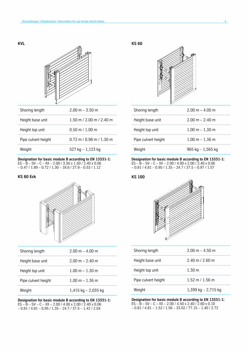
KVL
Shoring length 2.00 m – 3.50 m
Height base unit 1.50 m / 2.00 m / 2.40 m
Height top unit 0.50 m / 1.00 m
Pipe culvert height 0.72 m / 0.98 m / 1.30 m
Weight 527 kg – 1,123 kg
Designation for basic module B according to EN 13331-1: ES – B – SV – C – XX – 2.00 / 3.50 x 1.50 / 2.40 x 0.06 – 0.47 / 1.89 – 0.72 / 1.30 – 18.6 / 27.9 – 0.53 / 1.12 KS 60 Eck
Shoring length 2.00 m – 4.00 m
Height base unit 2.00 m – 2.40 m
Height top unit 1.00 m – 1.30 m
Pipe culvert height 1.00 m – 1.36 m
Weight 1,415 kg – 2,035 kg
Designation for basic module B according to EN 13331-1: ES – B – SV – C – XX – 2.00 / 4.00 x 2.00 / 2.40 x 0.06 – 0.81 / 4.81 – 0.95 / 1.35 – 24.7 / 37.5 – 1.42 / 2.04
KS 60
Shoring length 2.00 m – 4.00 m
Height base unit 2.00 m – 2.40 m
Height top unit 1.00 m – 1.30 m
Pipe culvert height 1.00 m – 1.36 m
Weight 965 kg – 1,565 kg
Designation for basic module B according to EN 13331-1: ES – B – SV – C – XX – 2.00 / 4.00 x 2.00 / 2.40 x 0.06 – 0.81 / 4.81 – 0.95 / 1.35 – 24.7 / 37.5 – 0.97 / 1.57
KS 100
Shoring length 2.00 m – 4.50 m
Height base unit 2.40 m / 2.60 m
Height top unit 1.30 m
Pipe culvert height 1.52 m / 1.56 m
Weight 1,399 kg – 2,715 kg
Designation for basic module B according to EN 13331-1: ES – B – SV – C – XX – 2.00 / 4.50 x 2.40 / 2.60 x 0.10 – 0.81 / 4.81 – 1.52 / 1.56 – 33.02 / 77.15 – 1.40 / 2.72

thyssenkrupp | Infrastructure | Instructions for use krings trench boxes 4
KS 100 Eck
Shoring length 2.50 m – 4.50 m
Height base unit 2.40 m / 2.60 m
Height top unit 1.40 m
Pipe culvert height 1.50 m / 1.55 m
Weight 1,799 kg – 2,945 kg
Designation for basic module B according to EN 13331-1: ES – B – SV – C – XX – 2.50 / 4.50 x 2.40 / 2.60 x 0.10 – 1.82 / 5.82 – 1.50 / 1.55 – 44.12 / 61.61 – 1.80 / 2.95
Piling frame element BLU
Shoring length 2.41 m
Height piling frame element 0.72 m
Pipe culvert height variable
Weight 465 kg
Designation for basic module B according to EN 13331-1: GV – B – SV – C – XX – 2.41 x 0.72 x 0.21 / 0.31 – 0.77 / 4.81 – variable – 17.5 / 46.2 / 56.1 – 0.47
Piling frame element universal DKU
Shoring length 2.27 m / 3.81 m
Height piling frame element 1.00 m
Pipe culvert height variable
Weight 1,320 kg – 1,870 kg
Designation for basic module B according to EN 13331-1: GV – B – SV – C – XX – 2.27 / 3.81 x 1.00 x 0.31 – 1.27 / max. – 1.32 / 1.87
Sheet pile element KKP
Shoring length 2.84 m / 4.07 m
Height piling frame element 0.48 m / 1.00 m
Pipe culvert height variable
Weight 293 kg – 1,020 kg
Designation for basic module B according to EN 13331-1: GV – B – SV – C – XX – 2.84 / 4.07 x 0.48 / 1.00 x 0.21 / 0.31 – 0.77 / 4.81 – variable – 17.5 / 46.2 / 56.1 – 0.29 / 1.02
thyssenkrupp | Infrastructure | Instructions for use krings trench boxes 5
2 Occupational safety and general information in accordance with DIN EN 13331-1/-2
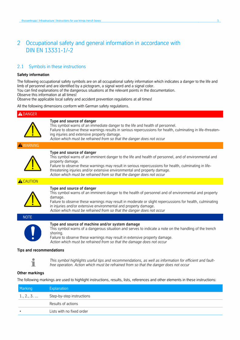
2.1 Symbols in these instructions
Safety information
The following occupational safety symbols are on all occupational safety information which indicates a danger to the life and limb of personnel and are identified by a pictogram, a signal word and a signal color. You can find explanations of the dangerous situations at the relevant points in the documentation. Observe this information at all times! Observe the applicable local safety and accident prevention regulations at all times!
All the following dimensions conform with German safety regulations.
DANGER
Type and source of danger This symbol warns of an immediate danger to the life and health of personnel. Failure to observe these warnings results in serious repercussions for health, culminating in life-threaten-ing injuries and extensive property damage. Action which must be refrained from so that the danger does not occur
WARNING
Type and source of danger This symbol warns of an imminent danger to the life and health of personnel, and of environmental and property damage. Failure to observe these warnings may result in serious repercussions for health, culminating in life-threatening injuries and/or extensive environmental and property damage. Action which must be refrained from so that the danger does not occur
CAUTION
Type and source of danger This symbol warns of an imminent danger to the health of personnel and of environmental and property damage. Failure to observe these warnings may result in moderate or slight repercussions for health, culminating in injuries and/or extensive environmental and property damage. Action which must be refrained from so that the danger does not occur
NOTE
Type and source of machine and/or system damage This symbol warns of a dangerous situation and serves to indicate a note on the handling of the trench shoring. Failure to observe these warnings may result in extensive property damage. Action which must be refrained from so that the damage does not occur
Tips and recommendations
This symbol highlights useful tips and recommendations, as well as information for efficient and fault-free operation. Action which must be refrained from so that the danger does not occur
Other markings
The following markings are used to highlight instructions, results, lists, references and other elements in these instructions:
Marking Explanation
1., 2., 3. ... Step-by-step instructions
Results of actions
• Lists with no fixed order

thyssenkrupp | Infrastructure | Instructions for use krings trench boxes 6
2.2 Dangers
When working on and in excavations and trenches, the following dangers with the potential to cause serious injuries or death arise, among others:
• Being buried under volumes of soil or gravel which slip
• Being buried as a result of failure of the shoring
• Personnel falling
• Being affected by falling or tipping parts
• Tripping, slipping, falling
• Forced postures in confined working spaces
• Crushing of hand and feet during loading and unloading, transportation, assembly and disassembly, and installation and removal of the shoring elements
2.3 General safety information and measures for reduction of risks
Please note that an appropriate risk assessment must be generated for the specified work step before assembly, installation and removal and disassembly of the shoring system.
Compliance with the technical specifications and safety information in these use instructions is required at all times.
DANGER
Risk of death or injury owing to insufficient safety measures on the construction site and for adjacent installations / trades! Insufficient safety measures on the construction site and for adjacent installations / trades result in a risk of death or injury, as well as a risk of property damage to the shoring! • Attention must be paid to overhead lines during transportation and during installation and removal of the
shoring. • On sloping or uneven ground, the shoring must set up at as close to a right angle to the slope as possible. • The use instructions must be present of the construction site.
• When using the shoring system, the maximum permitted loads as specified in these use instructions may not be exceeded.
• Shoring systems may only be used in ground which is not susceptible to slippage; water table drawdown measures must be taken where applicable.
• The stability of the shoring must be ensured in all installation and removal, assembly and disassembly states.
• The shoring must be installed in a horizontal position.
• Only put up shoring units on solid and even surfaces and secure against falling where applicable – possible factors which may affect stability, e.g. site incline, wind loads, vibrations from traffic loads and/or work tools, soil condition, etc., must be taken into account.
• Take traffic safety measures us trenches are established in the vicinity of public roads or if the establishment affects traffic. Consult with the relevant authorities.
• The shoring must reach to the bottom of the trench. In minimum stiff, cohesive soils, the shoring for con-struction operations which will be finished in a few days may end up to 0.50 m above the bottom of the trench if there are no exceptional influences and no earth pressure is to be absorbed from building loads.
• Throughout the construction phase, the front area must be secured through frictional connection and/or bat-tered in accordance with the national regulations.
• Shoring elements placed on top of one another must be frictionally connected to one another at all points provided for in the design.
• Cavities should be filled immediately in a force-fitting manner.
• In order to ensure the safe execution of works, material transportation, and in particular the rescue of in-jured personnel, minimum working area widths in accordance with DIN 4124 must be complied with (mini-mum working are width for excavations/trenches ≥ 0.6 m); the appropriate national regulations must be ap-plied where applicable.
• All parts of the shoring must always be inspected after heavy rainfall, in the event of significant changes to the loading, at the onset of a thaw, after a long interruption in the works, after extraordinary stresses (e.g. owing to impacts or vibrations) or after blasts.
• Removal of the shoring must be done in conjunction with backfilling.

thyssenkrupp | Infrastructure | Instructions for use krings trench boxes 7
TIP
• The safety of vehicles and persons on site must be ensured by means of cones, warning tape or security personnel spe-cially deployed for this purpose.
• The construction site must be sufficiently marked as such using warning signs, for example.
2.4 Protection against falls and falling parts
DANGER
Risk of death or injury owing to falls or falling parts! Falls or falling parts result in a risk of death or injury, as well as a risk of property damage to the machine and/or system! The following measures must be implemented, depending on the construction site. • Transitions are required for trenches with a width of > 0.80 m; the transitions must be at least 0.50 m wide.
• At a trench depth of > 1.00 m, the transitions must be equipped with a three-part side guard on both sides to protect against falling.
• At a trench depth of > 1.25 m, steps or ladders must be used for access.
• In order to protect against falling parts or against excavated soil slipping back in, the shoring must have an overhang over the top edge of the trench – at trench depths of 2.0 m this must be min. 5 cm, at trench depths of greater than 2.0 m it must be min. 10 cm.
• The front sides of the trenches or excavations must either be secured using appropriate shoring systems or, depending on the soil condition, battered accordingly.
• At the top edge, a protective strip which is at least 0.60 m wide must be kept free from loads and in particu-lar from construction machinery and vehicles.
• Fall protection systems must be installed in excavations and trenches with a possible fall height of greater than 2 m.
• For activities for which the installation of effective fall protection is generally not possible (e.g. during instal-lation of the shoring, during excavation, during cable laying or during backfilling), this must be reviewed and justified within the risk assessment.
2.5 Storage, transportation and lifting operations
Storage
DANGER
Risk of death or injury owing to incorrect storage! Incorrect storage results in a risk of death or injury, as well as a risk of property damage to the machine and/or system! • The shoring elements may only be stored on solid, even ground.
• In the event that shoring panels are stored in stacks, the maximum permitted stack height must be observed – rule of thumb: max. stack height [m] = 4 x width of the narrow side [m].
• Care must be taken to ensure that the shoring panels are aligned perpendicular with one another during storage and transportation; support staves and non-slip mats or similar must be used where applicable in order to ensure safe storage and safe transportation.
• The prescribed safety distances from trench and excavation walls (see 2.3) must always be complied with for storage.
thyssenkrupp | Infrastructure | Instructions for use krings trench boxes 8
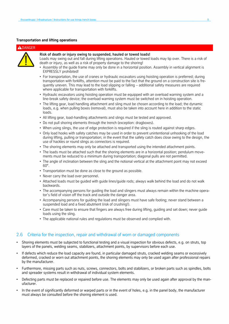
Transportation and lifting operations
DANGER
Risk of death or injury owing to suspended, hauled or towed loads! Loads may swing out and fall during lifting operations. Hauled or towed loads may tip over. There is a risk of death or injury, as well as a risk of property damage to the shoring! • Assembly of the guide frame may only be done in a horizontal position. Assembly in vertical alignment is
EXPRESSLY prohibited!
• For transportation, the use of cranes or hydraulic excavators using hoisting operation is preferred; during transportation with forklifts, attention must be paid to the fact that the ground on a construction site is fre-quently uneven. This may lead to the load slipping or falling – additional safety measures are required where applicable for transportation with forklifts.
• Hydraulic excavators using hoisting operation must be equipped with an overload warning system and a line-break safety device; the overload warning system must be switched on in hoisting operation.
• The lifting gear, load handling attachment and sling must be chosen according to the load; the dynamic loads, e.g. when pulling boxes (removal), must also be taken into account here in addition to the static loads.
• All lifting gear, load-handling attachments and slings must be tested and approved.
• Do not pull shoring elements through the trench (exception: dragboxes).
• When using slings, the use of edge protection is required if the sling is routed against sharp edges.
• Only load hooks with safety catches may be used in order to prevent unintentional unhooking of the load during lifting, pulling or transportation; in the event that the safety catch does close owing to the design, the use of hackles or round slings as connectors is required.
• The shoring elements may only be attached and transported using the intended attachment points.
• The loads must be attached such that the shoring elements are in a horizontal position; pendulum move-ments must be reduced to a minimum during transportation; diagonal pulls are not permitted.
• The angle of inclination between the sling and the notional vertical at the attachment point may not exceed 60°.
• Transportation must be done as close to the ground as possible.
• Never carry the load over personnel.
• Attached loads must be guided with guide lines/guide rods; always walk behind the load and do not walk backwards.
• The accompanying persons for guiding the load and slingers must always remain within the machine opera-tor’s field of vision off the track and outside the danger area.
• Accompanying persons for guiding the load and slingers must have safe footing; never stand between a suspended load and a fixed abutment (risk of crushing!).
• Care must be taken to ensure that fingers are always free during lifting, guiding and set down; never guide loads using the sling.
• The applicable national rules and regulations must be observed and complied with.
2.6 Criteria for the inspection, repair and withdrawal of worn or damaged components
• Shoring elements must be subjected to functional testing and a visual inspection for obvious defects, e.g. on struts, top layers of the panels, welding seams, stabilizers, attachment points, by supervisors before each use.
• If defects which reduce the load capacity are found, in particular damaged struts, cracked welding seams or excessively deformed, cracked or worn out attachment points, the shoring elements may only be used again after professional repairs by the manufacturer.
• Furthermore, missing parts such as nuts, screws, connectors, bolts and stabilizers, or broken parts such as spindles, bolts and spreader systems result in withdrawal of individual system elements.
• Defecting parts must be replaced or repaired before use. The elements may only be used again after approval by the man-ufacturer.
• In the event of significantly deformed or warped parts or in the event of holes, e.g. in the panel body, the manufacturer must always be consulted before the shoring element is used.

thyssenkrupp | Infrastructure | Instructions for use krings trench boxes 9
• Small repairs may be carried out by the user himself where applicable – however this may only be done in consultation with the manufacturer.
• Only original parts from the manufacturer may be used.
• The manufacturer provides no warranty for repairs which are improperly performed and for the use of parts which are not original parts.
• Before each (repeated) use and after reassembly of the shoring elements or after exceptional disturbances (see chapter 2.2), the tightness of all screw connections must be checked and they must be tightened where necessary.
• If there is any doubt about the usability of the shoring elements, and in the event of defects and damage, the manufacturer must be contacted.
• Soil which has adhered to the shoring elements must be cleaned off after use.
• In order to increase the service life, regular renewal of the pain (rust protection, top coat) is recommended.
2.7 The following, as amended, apply in particular:
Regulations issued by the BG [German Employers’ Liability Insurance Association] – Civil Engineering Technical Committee
• DIN 4124 “Excavations and trenches”
• DIN EN 13331 Part 1 – Product specifications, Part 2 – Assessment by calculation or test
• General safety information and the Industrial Safety Regulation
Our products bear the “tested for safety” GS mark.
2.8 Personal protective equipment (PPE)
Personal protective equipment serves to protect personnel against health and safety risk while working.
In principle, the necessary personal protective equipment for the activities is the result of your risk assessment.
We recommend the following PPE for loading and unloading activities, assembly and disassembly, transportation/lifting opera-tions, maintenance and repair, and for activities in the area with shoring:
PROTECTIVE CLOTHING
Protective clothing is tight-fitting workwear which tears easily, with tight sleeves and with no protruding parts.
SAFETY HELMET
Safety helmets protect the head against falling objects, swinging loads and impacts against fixed objects.
PROTECTIVE GLOVES
Protective gloves protect the hands against friction, abrasions, deeper injuries.
SAFETY SHOES
Safety shoes protect the feet against crushing, falling parts and slipping on slippery surfaces. Further-more, S3 safety shoes are puncture-resistant and thus protect against injuries to the feet resulting from nails, metal chips, etc.
2.9 Technical data of the shoring elements
The technical data of the shoring elements used can be found in the current version of the technical manual. The technical manual is available at https://www.thyssenkrupp-infrastructure.com

thyssenkrupp | Infrastructure | Instructions for use krings trench boxes 10
3 Installation instructions for edge-supported shoring systems krings
Before starting the work, it is obligatory to observe all safety precautions from section “Occupational health and safety and general remarks according to DIN EN 13331-1/-2” (see section 2 Occupational health and safety and general remarks accord-ing to DIN EN 13331-1/-2 from page 3)!
1. Positioning the panel half on the ground
Place the first panel half on level ground with the guide frame facing upwards.
Insert the pretensioned spring mushrooms into the guide frame, insert the corresponding locking pins into the pro-vided locating holes of the guide post and the spring mush-room and secure by means of spring cotters.
Release the spring mushroom by loosening the nuts.
2. Inserting spindles
Insert struts into the spring mushrooms, insert locking pins and secure with spring cotters (see detail X).
If required, i. e. according to the trench width, a maximum of 7 intermediate pipes can be used per strut unit. These are placed on the struts, alternately offset for static rea-sons, fixed with socket pins and secured with spring cot-ters.
thyssenkrupp | Infrastructure | Instructions for use krings trench boxes 11
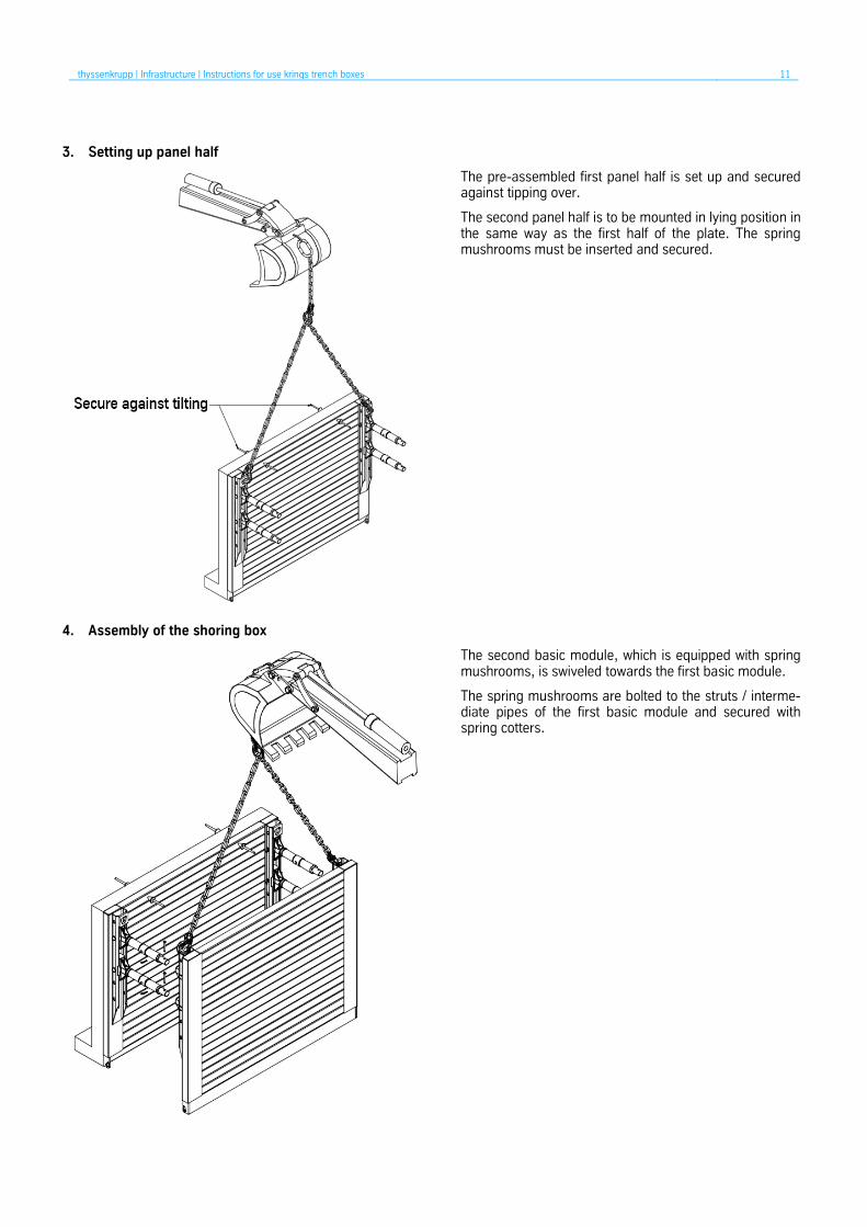
3. Setting up panel half
The pre-assembled first panel half is set up and secured against tipping over.
The second panel half is to be mounted in lying position in the same way as the first half of the plate. The spring mushrooms must be inserted and secured.
4. Assembly of the shoring box
The second basic module, which is equipped with spring mushrooms, is swiveled towards the first basic module.
The spring mushrooms are bolted to the struts / interme-diate pipes of the first basic module and secured with spring cotters.

thyssenkrupp | Infrastructure | Instructions for use krings trench boxes 12
3.1 Installation instructions krings shoring corner
Before starting the work, it is obligatory to observe all “Occupational health and safety and general remarks according to DIN EN 13331-1/-2” safety precautions (see Section 2 Occupational health and safety and general remarks according to DIN EN 13331-1/-2 on page 3). 1. Delivery
The krings shoring corner is delivered in folded condition.
Position the shoring corner on a sufficiently large, level and stable surface.
Use squared timber!
Before using it in the trench, remove the transport securing device first.
2. Removing the transport securing device
During transport, both panel parts are secured with squared timber and screws.
Before removing the transport securing device, secure the upper panel half with a lifting device in position.
The hexagon screw (M20) can then be loosened (30 mm width across flats).
thyssenkrupp | Infrastructure | Instructions for use krings trench boxes 13
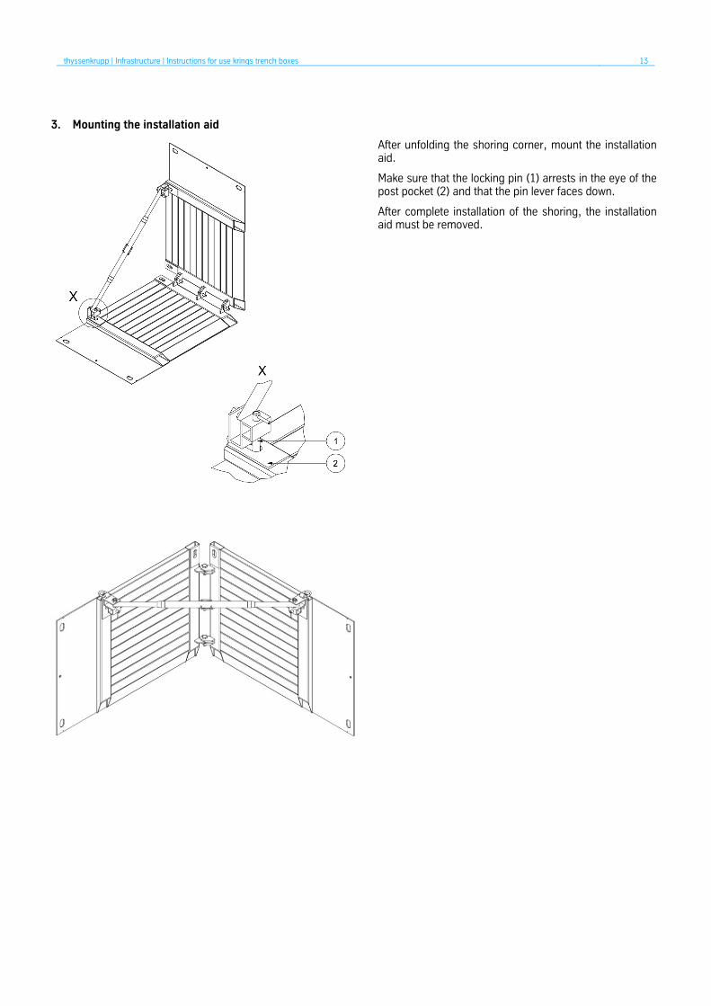
3. Mounting the installation aid
After unfolding the shoring corner, mount the installation aid.
Make sure that the locking pin (1) arrests in the eye of the post pocket (2) and that the pin lever faces down.
After complete installation of the shoring, the installation aid must be removed.

thyssenkrupp | Infrastructure | Instructions for use krings trench boxes 14
3.2 Installation instructions krings length compensation
Before starting the work, it is obligatory to observe all “Occupational health and safety and general remarks according to DIN EN 13331-1/-2” safety precautions (see Section 2 Occupational health and safety and general remarks according to DIN EN 13331-1/-2 on page 3). 1. Delivery and preassembly of the first panel half
First, position the krings length compensation – LAV on a sufficiently level and stable surface.
Then, insert the KVL spindles (1) from the top onto the traverses.
They are secured by a pin (2) and spring cotter (3).
2. Erecting the pre-assembled panel half
The shoring box must be assembled standing up.
For this purpose, erect the panel half with the struts and secure it from tipping over.
If required, a second excavator must secure the shoring box for the entire installation process.

thyssenkrupp | Infrastructure | Instructions for use krings trench boxes 15
3. Assembling the box
Bring the second panel half with lifting gear to the first panel half, secured in vertical position, and fasten it with pins as described above under item 1.
3.3 Installation instructions krings piling frame shoring
Installation of the krings piling frame shoring is identical to the installation of the krings length compensation (see Section 3.2).

thyssenkrupp | Infrastructure | Instructions for use krings trench boxes 16
4 Assembly instructions for edge-supported shoring systems krings
Note: According to DIN EN 13331, edge-supported shoring systems are abbreviated with the letters ES.
Shoring products based on the KVL system shall only be inserted with insertion process.
4.1 Insertion process
1. Preconditions
For all work, observe the applicable regulations from DIN, EN, UVV [German accident prevention regulations] and BGBau [German employers’ liability insurance association for the construction industry].
In the insertion process, trench shoring units are inserted into a section of trench which has already been excavated to its final depth according to the provisions in DIN 4124.
The insertion process is only permissible if the following preconditions have been fulfilled:
Temporarily firm ground Vertical trench walls Same trench width for the entire length of the shoring unit Keep out of the trench until the shoring unit has been inserted into it. There must be no crossing pipes, buildings or other structures and / or traffic areas within the range of the trench. The degree of anticipated settlement, loosening and displacement of soil within the range of the trench is acceptable.
The ground is considered temporarily firm if no major crumbling is noted in the period from the start of excavation until the insertion of the shoring.
The permitted load values in accordance with the technical data of the shoring system employed must be observed at all times. For details concerning the trench width, refer to DIN 4124.
It is forbidden at all times to enter trenches with a trench depth ≥ 1.25 m without shoring or slope. It is also prohibited to stay or to work with heavy machinery in the area of risk e. g. the edge of the pit.
2. Use of top panels
During the insertion process, the assembly of the base (B) and top module (T) must be carried out outside the trench.
The system must be set as a whole in the trench if shoring boxes with top boxes are required to secure deeper trenches.
Base and top modules are connected by stanchions (1) and pins with spring cotters (2).
The system is assembled by using a lifting gear and suita-ble lifting slings (GS approval).
The lifting slings must be hooked exclusively and at least four points (ES) into the lifting eyes (3) provided for this purpose.

thyssenkrupp | Infrastructure | Instructions for use krings trench boxes 17
3. Assembly
The shoring system prepared outside the pit is inserted with lifting gear and suitable and lifting slings (GS approval) into the trench which has been excavated in the final depth for the length and width of a shoring box.
The length of the excavated and unsecured trench section must be limited to a length required for the insertion of one single trench shoring unit.
The gap between the trench wall and the inserted shoring unit must be backfilled right up to the top. In addition, the shoring unit should be pressed against the trench wall by spindling out the struts.
The permitted load values in accordance with the technical data of the shoring system employed must be observed at all times. For details concerning the trench width, refer to DIN 4124.
4.1.1 Insertion of the krings length compensation
The LAV element set to the width of the trench is inserted with lifting gear and suitable and tested lifting slings into the exca-vated trench and aligned up to the transversal obstacle.
The length compensation area must fit closely to the previous shoring element. Make sure that the length compensation area protrudes up to the V mark over the contacting formwork (min. 10 cm overlap) for safety reasons.
If the LAV element is not used as length compensation, it must be positioned flush at the last inserted shoring element.
As soon as the LAV element is in the correct position, the element is pressed to the trench wall by turning the shoring spindles. The gap between the trench wall and the installed shoring element must be backfilled right up to the top.
thyssenkrupp | Infrastructure | Instructions for use krings trench boxes 18
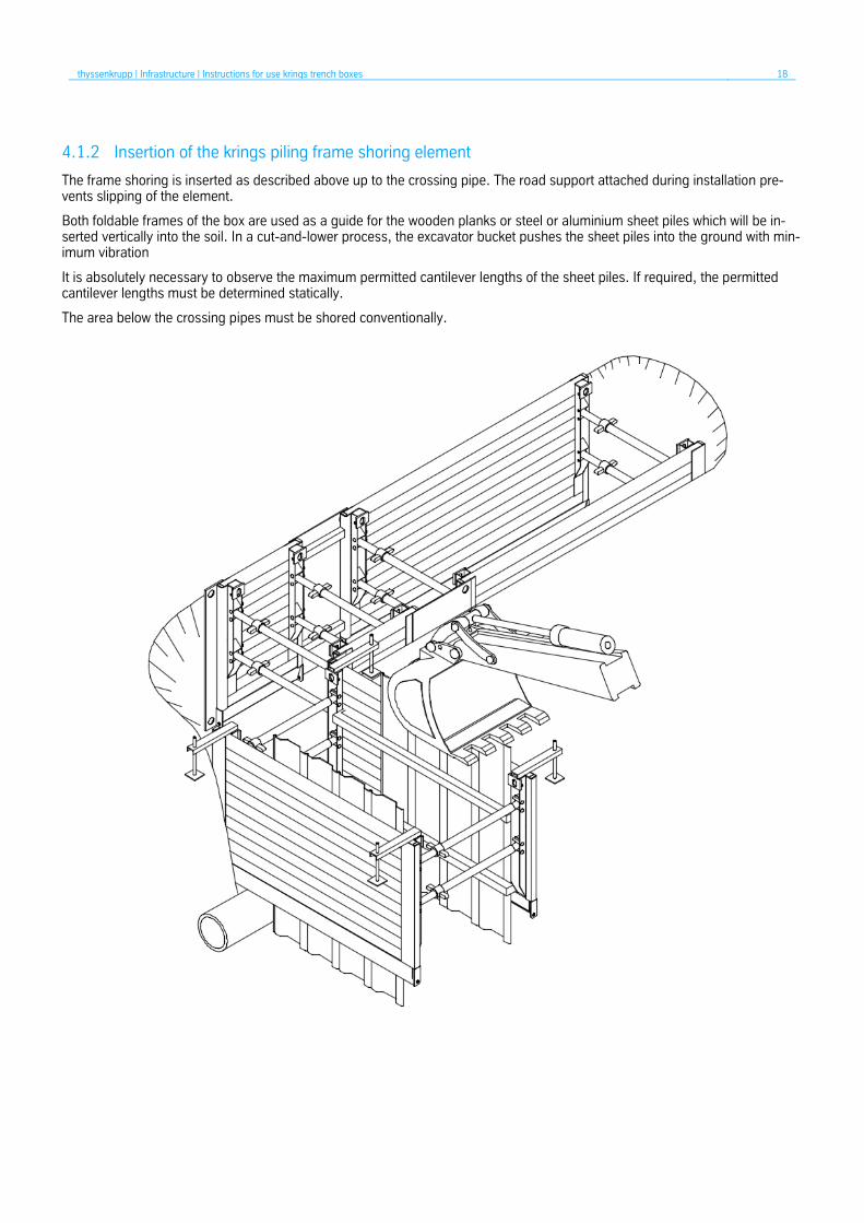
4.1.2 Insertion of the krings piling frame shoring element
The frame shoring is inserted as described above up to the crossing pipe. The road support attached during installation pre-vents slipping of the element.
Both foldable frames of the box are used as a guide for the wooden planks or steel or aluminium sheet piles which will be in-serted vertically into the soil. In a cut-and-lower process, the excavator bucket pushes the sheet piles into the ground with min-imum vibration
It is absolutely necessary to observe the maximum permitted cantilever lengths of the sheet piles. If required, the permitted cantilever lengths must be determined statically.
The area below the crossing pipes must be shored conventionally.

thyssenkrupp | Infrastructure | Instructions for use krings trench boxes 19
4.1.3 Insertion of the krings shoring corner
The krings shoring corner – UVP completes the shoring elements described above. The shoring corner is positioned with suita-ble and tested lifting slings close to the previously inserted shoring element and inserted into the trench.
Make sure that the length compensation area protrudes up to the V mark over the contacting formwork (min. 10 cm overlap) for safety reasons.
To avoid movement of the krings shoring corner, spread a suitable support between the shoring corner and the next shoring element.
The gap between the trench wall and the inserted shoring corner must be backfilled up to the top.
thyssenkrupp | Infrastructure | Instructions for use krings trench boxes 20
4.2 Lowering procedure
1. General
In the lowering procedure, trench shoring units or parts thereof are pressed vertically into the ground.
The lowering procedure is only permitted for edge-supported shoring systems. Centrally supported trench shoring systems must not be used in the lowering procedure.
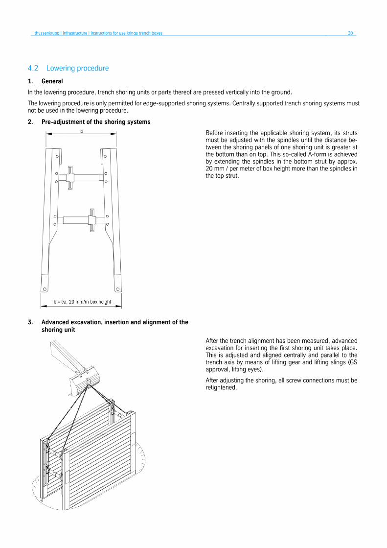
2. Pre-adjustment of the shoring systems
Before inserting the applicable shoring system, its struts must be adjusted with the spindles until the distance be-tween the shoring panels of one shoring unit is greater at the bottom than on top. This so-called A-form is achieved by extending the spindles in the bottom strut by approx. 20 mm / per meter of box height more than the spindles in the top strut.
3. Advanced excavation, insertion and alignment of the shoring unit
After the trench alignment has been measured, advanced excavation for inserting the first shoring unit takes place. This is adjusted and aligned centrally and parallel to the trench axis by means of lifting gear and lifting slings (GS approval, lifting eyes).
After adjusting the shoring, all screw connections must be retightened.

thyssenkrupp | Infrastructure | Instructions for use krings trench boxes 21
4. Lowering the shoring system
Lowering takes place alternately with the soil excavation
During the lowering process, the advance soil excavation underneath the panels must not exceed 0.50 m. During the alternate pushing of the shoring walls, care must be taken to ensure that the possible angle of rotation in a vertical plane between strut and shoring wall does not exceed = +/- 8°.
Pressure plates and / or pressure beams (D) must be used for the lowering process. Care must be taken to ensure that the shoring panels are not used as “chisel”.
5. Top panel
Depending on the required trench depth, top modules (T) are mounted on the base modules (B). Base and top mod-ules are to be connected by stanchions (1) and pins (2). Here too, pressure plates and / or pressure beams must be used for the further lowering process.
6. Installation of the next shoring field
The next shoring unit is installed as soon as the previous system has been fully lowered to the bottom of the trench.
The installation is carried out according to the previously described points.
The shoring must be complete. Wall sections that cannot be secured with shoring units, e. g. pipes that cross each other under certain conditions, must be installed sepa-rately.
thyssenkrupp | Infrastructure | Instructions for use krings trench boxes 22
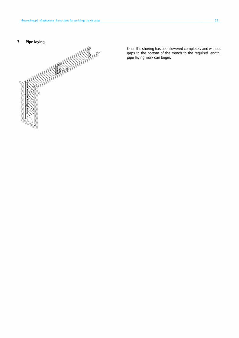
7. Pipe laying
Once the shoring has been lowered completely and without gaps to the bottom of the trench to the required length, pipe laying work can begin.

thyssenkrupp | Infrastructure | Instructions for use krings trench boxes 23
5 Instructions for removing for edge-supported shoring systems krings
1. Removing, backfilling and compacting
After completing the pipe-laying work the shoring is removed with layer-by-layer backfilling and compacting. To this end, the shoring is extracted step-by-step in accordance with the instructions of the local site management and the expert’s specifications and the backfilling material returned to the trench is compacted against the existing soil.
Lifting slings may only be attached to the provided attachment points.
Also during removal, the possible rotation angle in a vertical level between strut and shoring wall may not exceed =+/- 8°.
2. Service and maintenance
All shoring components must be checked for proper functioning before they are used in subsequent shoring fields.
Defective parts must be replaced and / or repaired.
Minor repairs can be carried out by the user after consultation with the manufacturer.
Only use original spare parts from the manufacturer!
No warranty for improperly performed repairs and use of non-original parts.
thyssenkrupp | Infrastructure | Instructions for use krings trench boxes 24
6 Assembly instructions piling frame shoring
1. General
The piling frame shoring is a universal and economical shoring method in inner-city areas, especially for crossing pipes. The two opposite piling frame elements, supported against each other with struts, serve as upper guides for trench sheets to be inserted vertically into the ground.
The trench sheets can be inserted by static pressing with an excavator bucket or by vibration method. Installation and presetting of the piling frame element are carried out in the same way as for edge-supported shoring systems.
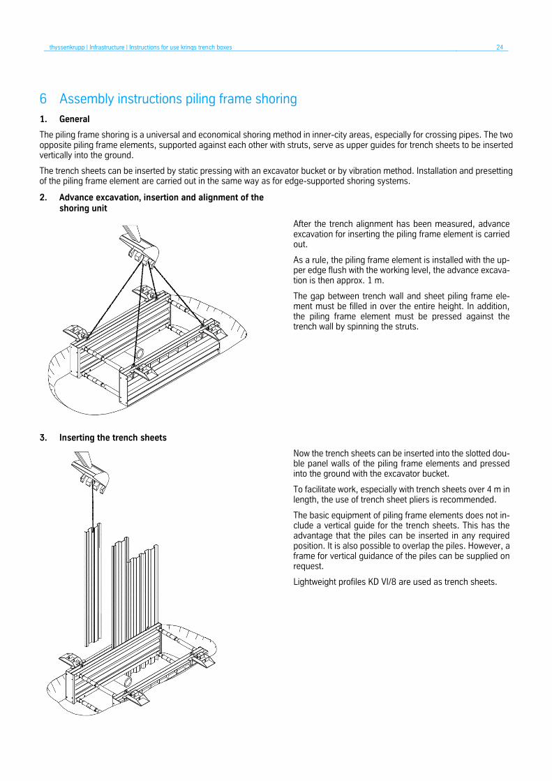
2. Advance excavation, insertion and alignment of the shoring unit
After the trench alignment has been measured, advance excavation for inserting the piling frame element is carried out.
As a rule, the piling frame element is installed with the up-per edge flush with the working level, the advance excava-tion is then approx. 1 m.
The gap between trench wall and sheet piling frame ele-ment must be filled in over the entire height. In addition, the piling frame element must be pressed against the trench wall by spinning the struts.
3. Inserting the trench sheets
Now the trench sheets can be inserted into the slotted dou-ble panel walls of the piling frame elements and pressed into the ground with the excavator bucket.
To facilitate work, especially with trench sheets over 4 m in length, the use of trench sheet pliers is recommended.
The basic equipment of piling frame elements does not in-clude a vertical guide for the trench sheets. This has the advantage that the piles can be inserted in any required position. It is also possible to overlap the piles. However, a frame for vertical guidance of the piles can be supplied on request.
Lightweight profiles KD VI/8 are used as trench sheets.

thyssenkrupp | Infrastructure | Instructions for use krings trench boxes 25
4. Lowering the shoring system
After adjusting the trench sheets, lowering is carried out alternately with the soil excavation.
During the lowering process, the advanced soil excavation underneath the trench sheets must not exceed 0.50 m, de-pending on the soil conditions. Any pipes that may be crossing must be exposed beforehand and the trench sheet above it must be secured against further sinking. The use of shorter trench sheets is advantageous here.
The area below the crossing pipe must be conventionally secured with horizontal timber shoring. The adjacent trench sheets can be used as a support.
Care must be taken to ensure that the trench sheets are not used as “chisel”. Solid obstacles (e. g. unnatural fill-ings, rock) must be removed manually. To prevent subsid-ence, backfilling of the elements and trench sheets must be ensured with soil.
In the case of well drivable soils, the trench sheets can be inserted to their final depth. The soil is then subsequently excavated with a suitable excavator.
5. Additional walers
Depending on the required trench depth, measures to en-sure the stability of the shoring system may be required for static reasons. As with all trench shoring systems, a site-related static proof is required in accordance with DIN 4124.
Longitudinal waler beams must be installed at a depth of approx. 2 m from the top edge of the terrain. These must be secured against sinking on the piling frame element with suspension chains and supported against each other with waler struts. These waler beams must be lowered simulta-neously with the trench sheets to the statically required depth.
The next shoring unit is installed as soon as the previous system has been fully lowered to the bottom of the trench.
Depending on site conditions, this can be another piling frame element or another shoring system. After laying the pipes, the removal of the system takes place in reverse or-der.

thyssenkrupp | Infrastructure | Instructions for use krings trench boxes 26
7 Statics questionnaire
thyssenkrupp Infrastructure can carry out a static calculation on the basis of multiple requirements.
Company: Quote/order no:
Construction project:
Contact person: Mobile:
Tel.: Fax:
Email: Shoring system:
Shoring material dimensions:
(e.g. panel or box length and height, module length, etc.)
1. Trench/excavation dimensions:
Trench depth T [m] Trench width b [m] Clear shoring width bc [m]
Pipe culvert height hc [m] Pipe length l [m] Pipe diameter DN [mm]
2. Building impact:
yes no Distance between building and trench edge [m]:
Number of floors:
Foundation depth (lower edge of foundation) [m]:
3. Traffic loads:
3.1 Site traffic
yes no
3.2 Excavators
yes no Type/weight
Distance between vehicle and trench edge [m]
Vehicle position alongside trench
head ends of trench

thyssenkrupp | Infrastructure | Instructions for use krings trench boxes 27
3.3 Road traffic (load model 1) in accordance with DIN EN1991-2
Yes no Distance between vehicle and trench edge [m]
Vehicle position alongside trench
head ends of trench
3.4 Rail traffic in accordance with DIN EN 1991-2
yes no Type of rail traffic
Distance between axis and trench edge [m]
3.5 Crane
yes no Type/weight
Dimensions of support brackets [m]
Center distance of support brackets [m]
Max. support load per bracket [kN]
4. General information:
4.1 Can be sloped yes no Berm height h1 [m]:
4.2 Head end shoring yes no with:
4.3 Lines crossing the trench yes no Pipe Ø, height of bottom
of pipe
4.4 Concrete floor (building concrete) yes no
5. Soil-mechanical parameters
(please forward appropriate information from the geological survey, core samples or soil characteristics)
5.1 Site plan yes no
5.2 Geological survey yes no
5.3 Soil characteristics φ γ c
6. Other:

thyssenkrupp | Infrastructure | Instructions for use krings trench boxes 28
7. Drawing
Place, date Signature

Materials Services Infrastructure thyssenkrupp Infrastructure GmbH Hollestraße 7a 45127 Essen, Germany T: +49 201 844-562313 F: +49 201 844-562333 [email protected] www.thyssenkrupp-infrastructure.com
Trench Shoring
thyssenkrupp Infrastructure GmbH Ottostr. 30 41836 Hückelhoven, Germany P: +49 2433 453-0 F: +49 2433 453-100 [email protected]
TK
INF.
00
2.0
2.C
E.0
9-2
0.R
M.0
9-2
0