material joining isat 430 module 8. spring 2001isat 430 dr. ken lewis 2 joining technologies joining...
Post on 21-Dec-2015
217 views
TRANSCRIPT

Material Joining
ISAT 430
Module 8

Spring 2001 ISAT 430 Dr. Ken Lewis 2Module 8
Joining Technologies Joining is a many splendored thing.
Welding Arc or melting Resistance or other
Soldering & brazing Mechanical fastening (bolts & nuts). Seaming and crimping Adhesive bonding
All are important for different reasons.

Spring 2001 ISAT 430 Dr. Ken Lewis 3Module 8
The Joined Vehicle

Spring 2001 ISAT 430 Dr. Ken Lewis 4Module 8
Why Join? The product may be impossible to make as a single piece. (See
previous slide) It may be more economical to make in pieces
A cooking pot (pot + handle) Complicated products may be needed to taken apart for repair
Sewing machines, cars, hair dryers,…….. Parts may have different functional purposes
Brake systems.
Rotors pads

Spring 2001 ISAT 430 Dr. Ken Lewis 5Module 8
Why Join2?
Making and assembling in one spot may be impossible The space shuttle Bridges Pianos …

Spring 2001 ISAT 430 Dr. Ken Lewis 6Module 8
Welding Fusion welding
Use heat to melt the base metals In many operations a filler metal is added to the
molten pool Adds bulk and strength to the joint.
Solid state welding Pressure or heat and pressure cause the coalescence
If heat is used, the temperature is below the melting point of the joined metals
No filler metal is used.

Spring 2001 ISAT 430 Dr. Ken Lewis 7Module 8
Weld joints
Spring 2001 ISAT 430 Dr. Ken Lewis 8Module 8
Fusion Welding Oxyfuel gas welding
Uses a fuel gas and oxygen to produce the heat. Arc welding
Heating is accomplished by an electric arc Resistance welding
Heating is accomplished by the passage of an electric current
Others Electron beam and laser welding

Spring 2001 ISAT 430 Dr. Ken Lewis 9Module 8
Flux One hears the word “FLUX” (Latin == ‘to flow’)
bandied about. All purpose word describing a material which
Protects the materials from unwanted oxidation Helps dissolve and remove oxides Provides a gaseous shield around the weld point

Oxy Acetylene Welding

Spring 2001 ISAT 430 Dr. Ken Lewis 11Module 8
Oxyfuel welding Most common process uses acetylene, C2H2 as the
fuel. Heat is generated by two chemical reactions:
C2H2 + O2 2CO + H2 + Heat
CO + H2 + O2 CO2 + H2O
Temperatures in these flames can reach 3,300°C (6,000°F)

Spring 2001 ISAT 430 Dr. Ken Lewis 12Module 8
Oxyacetylene Welding The flame is directed by a
welding torch. A filler metal is sometimes
added Usually coated with a
flux Heat efficiency is low ~0.1
– 0.3 Flame spreading, losses
to the air, etc.

Spring 2001 ISAT 430 Dr. Ken Lewis 13Module 8
Oxy acetylene flames Neutral flame
Gas:Fuel = 1:1 Useful
Oxidizing flame Excess oxygen Harmful to steel Useful in copper and
copper based alloys Thin film of slag forms
over the molten metal for protection.

Spring 2001 ISAT 430 Dr. Ken Lewis 14Module 8
Oxy acetylene flames Reducing flame
Excess fuel. Temperature is lower Used for brazing,
soldering. Other fuels,
Hydrogen, propane, butane, natural gas
Not useful, because the heat is low and the flames are reducing.

Spring 2001 ISAT 430 Dr. Ken Lewis 15Module 8
Fuel Temperatures and Heats.Temperature Heat of Combustion
Fuel °F °C Btu/ft3 MJ/m3
Acetylene (C2H2) 5589 3087 1470 54.8
MAPP1 (C3H4) 5301 2927 5460 91.7
Hydrogen (H2) 4820 2660 325 12.1
Propylene (C3H6) 5250 2900 2400 89.4
Propane (C3H8) 4579 2526 2498 93.1
Natural Gas 4600 2538 1000 37.3
1) Methylacetylene propadiene

Spring 2001 ISAT 430 Dr. Ken Lewis 16Module 8
Oxy-acetylene welding summary Relatively cheap Well suited to low volume and repair jobs. Rarely used on stock thicker than ¼ inch Rarely mechanized
Thus relies on the skill of the welder for quality.

Arc Welding
Spring 2001 ISAT 430 Dr. Ken Lewis 18Module 8
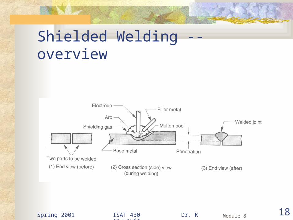
Shielded Welding -- overview

Spring 2001 ISAT 430 Dr. Ken Lewis 19Module 8
Arc Welding A fusion process wherein the coalescence of the
metals is achieved from the heat of an electric arc formed between an electrode and the work.
An electric arc is a discharge of electric current across a gap I a circuit.
It is sustained by the presence of a thermally ionized column of gas (called a plasma).
Temperatures up to 30,000°C (54,000°F) a generated

Spring 2001 ISAT 430 Dr. Ken Lewis 20Module 8
Arc Welding The clamp completes the
circuit A filler metal may be used.
Two kinds of welding electrode Consumable Non -- consumable

Spring 2001 ISAT 430 Dr. Ken Lewis 21Module 8
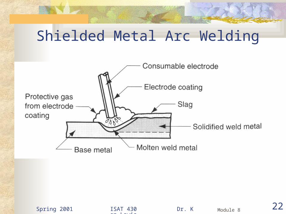
Consumable Electrode Welding Shielded Metal Arc Welding (SMAW)
Consumable electrode coated with chemicals that provide flux and shielding
Sometimes called ‘stick’ welding The filler metal (here the consumable electrode) is
usually very close in composition to the metal being welded.
The coating contains Cellulose, carbonates, a silicate binder Sometime other metals to alloy the joint
Spring 2001 ISAT 430 Dr. Ken Lewis 22Module 8
Shielded Metal Arc Welding

Spring 2001 ISAT 430 Dr. Ken Lewis 23Module 8
Consumable Electrode Welding Shielded Metal Arc Welding (SMAW)
The stick is about 12 – 18 inches long Applications
Construction, pipelines, shipbuilding, fabrication job shops
Used for Steels, stainless steels, cast irons
Not used for aluminum and its alloys, or copper and its alloys (energy density is too high)

Spring 2001 ISAT 430 Dr. Ken Lewis 24Module 8
Consumable Electrode Welding2
Gas Metal Arc Welding Electrode is a consumable bare metal wire
Usually continuous and fed from a spool The work area is protected by flooding it with a gas Wire diameters range from 1/32 to ¼ inch in
diameter

Spring 2001 ISAT 430 Dr. Ken Lewis 25Module 8
Gas Metal Arc Welding

Spring 2001 ISAT 430 Dr. Ken Lewis 26Module 8
Gas Metal Arc Welding Shielding Gases
Inert – Ar (Argon), He (Helium) Used for aluminum alloys and stainless steels
Active – CO2
Used for low and medium carbon steels
The combination of bare electrode wire and shielding gas eliminates slag in the work area Negates need for subsequent cleanup
Spring 2001 ISAT 430 Dr. Ken Lewis 27Module 8
Gas Metal Arc Welding Originally called “MIG” welding (for metal inert gas) Used widely in factory fabrication
Better metal usage (no stubs) Sticks or filler
High deposition rates No slag

Spring 2001 ISAT 430 Dr. Ken Lewis 28Module 8
Consumable Electrode Welding2
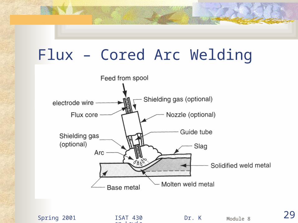
Flux – cored Arc Welding Developed in the 1950’ss Electrode is a continuous consumable tubing Interior of the electrode contains
Flux De-oxidizers Alloy elements
Spring 2001 ISAT 430 Dr. Ken Lewis 29Module 8
Flux – Cored Arc Welding

Spring 2001 ISAT 430 Dr. Ken Lewis 30Module 8
Flux – Cored Arc Welding Two versions
Self shielded Core contains flux and ingredients that generate a
shielding gas Gas shielded
Gas is applied externally
Used primarily for welding steels and stainless steels Noted for producing high quality smooth joints

Spring 2001 ISAT 430 Dr. Ken Lewis 31Module 8
Non-consumable Electrodes Gas Tungsten Arc Welding Known as “TIG” (tungsten inert gas) welding The electrode is W (tungsten)
Tm = 6170°F (3410°C)
Actually it is slowly consumed Shielding gases include Ar, He or a mixture

Spring 2001 ISAT 430 Dr. Ken Lewis 32Module 8
Gas Tungsten Arc Welding

Spring 2001 ISAT 430 Dr. Ken Lewis 33Module 8
Gas Tungsten Arc Welding (TIG) Used for a wide variety of metals
can also be used to weld dissimilar metals (but not very well)
Most commonly used for aluminum and stainless steel
For steel Slower and more costly than consumable welding Except for thin sections or where very high quality is
needed

Resistance Welding

Spring 2001 ISAT 430 Dr. Ken Lewis 35Module 8
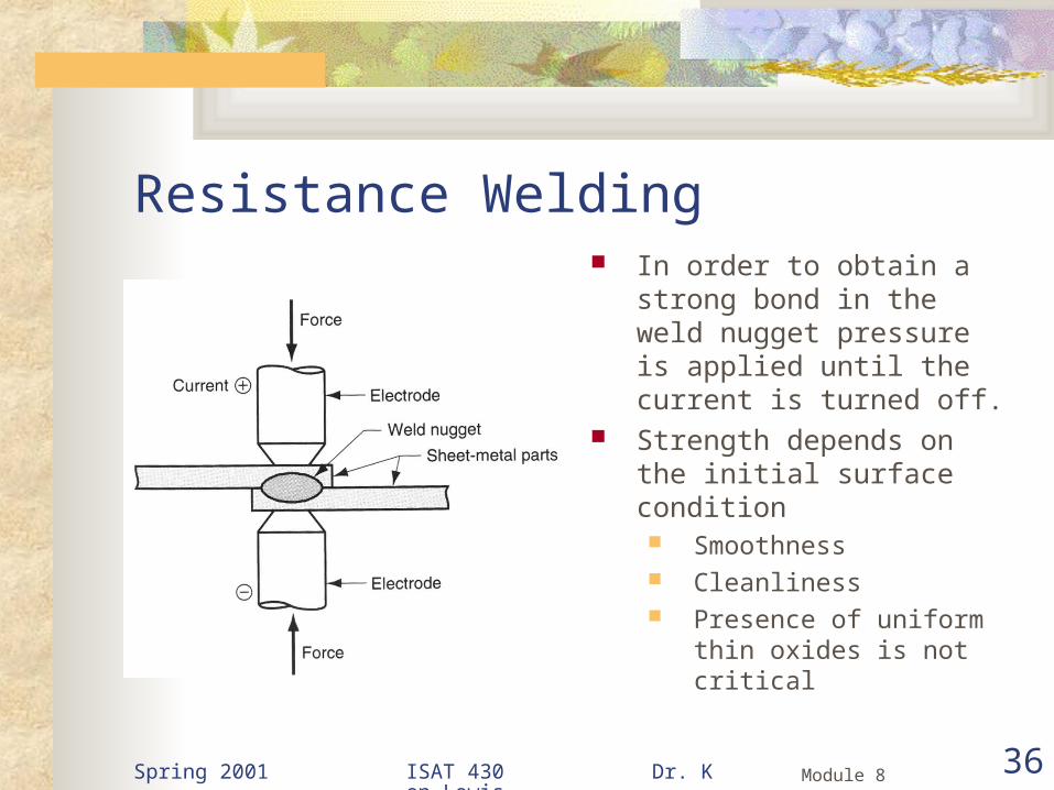
Resistance Welding This is a group of fusion welding processes that use
heat and pressure to make the coalescence.
The heat comes from electrical resistance to current flow at the site of the weld.
Spring 2001 ISAT 430 Dr. Ken Lewis 36Module 8
Resistance Welding In order to obtain a strong
bond in the weld nugget pressure is applied until the current is turned off.
Strength depends on the initial surface condition Smoothness Cleanliness Presence of uniform thin
oxides is not critical

Spring 2001 ISAT 430 Dr. Ken Lewis 37Module 8
Resistance Welding Currents range from 3,000
to 40,000A Heat generated is given by:
2Q I Rt
Where: I = current (amperes) R = resistance (ohms) T = time of current
(seconds) Q = heat in Joules

Spring 2001 ISAT 430 Dr. Ken Lewis 38Module 8
Resistance Welding The reason that the current
is so high is because the R is usually so low ~~ 0.0001 ohm
2Q I Rt
Where: I = current (amperes) R = resistance (ohms) T = time of current
(seconds) Q = heat in Joules

Spring 2001 ISAT 430 Dr. Ken Lewis 39Module 8
A resistance spot welding operation is performed on two pieces of 0.0625 in thick sheet steel using 12,000 A for 0.23 seconds. The electrodes are 0.25 in. in diameter. Resistance is assumed to be 0.0001 ohm and the resulting weld nugget is 025 in. dia. And 0.1 in. thick. The melting energy for this metal is 155 BTU/in3.
What portion of the heat generated was used to form the weld and what portion was merely siphoned off and dissipated into the surrounding metal?
From the equation above: 2Q I Rt
3312 sec 3.141055 sec
BTUQ W BTU
W
2(12,000) (0.0001)(0.23) 3312 secQ W

Spring 2001 ISAT 430 Dr. Ken Lewis 40Module 8
A resistance spot welding operation is performed on two pieces of 0.0625 in thick sheet steel using 12,000 A for 0.23 seconds. The electrodes are 0.25 in. in diameter. Resistance is assumed to be 0.0001 ohm and the resulting weld nugget is 025 in. dia. And 0.1 in. thick. The melting energy for this metal is 155 BTU/in3.
What portion of the heat generated was used to form the weld and what portion was merely siphoned off and dissipated into the surrounding metal?
The volume of the weld nugget is:2
4V d L
33
0.00491 0.761BTU
Q in BTUin
Assuming a disc
2 2 3(0.25) (0.1) 0.004914 4
V d L in
The heat necessary to melt this disc is

Spring 2001 ISAT 430 Dr. Ken Lewis 41Module 8
A resistance spot welding operation is performed on two pieces of 0.0625 in thick sheet steel using 12,000 A for 0.23 seconds. The electrodes are 0.25 in. in diameter. Resistance is assumed to be 0.0001 ohm and the resulting weld nugget is 025 in. dia. And 0.1 in. thick. The melting energy for this metal is 155 BTU/in3.
What portion of the heat generated was used to form the weld and what portion was merely siphoned off and dissipated into the surrounding metal?
The wasted heat is just
3.14 0.761100 76%
3.14waste
BTU BTUQ
BTU

Spring 2001 ISAT 430 Dr. Ken Lewis 42Module 8
Resistance Spot Welding1. Parts inserted
2. Electrodes close and force is applied
3. Weld time. Current switched on, force maintained
4. Current off, force maintained. Note: current sometimes left on at a reduced level for stress relief (micro anneal
5. Electrodes opened – repeat.

Spring 2001 ISAT 430 Dr. Ken Lewis 43Module 8
Explosion Welding First, some elimination of a preconceived notion
When something explodes, it does not just go KABLOOIE There are different rates of explosion.
Deflagration The reaction front proceeds at various rates, but at less than the
speed of sound in the deflagrating material. Black powder
Explosion The reaction front proceeds at speeds greater than the speed of
sound in the exploding material Immense pressure build up.

Spring 2001 ISAT 430 Dr. Ken Lewis 44Module 8
Explosion Welding2
It just seems like it goes KABLOOIE All are fast compared to normal burning
A slow explosion has a detonation rate of ~2,000 m/s This is a heave
A fast explosion will have detonation rates approaching 8,000 m/s. Provides brisance (a slap)
Spring 2001 ISAT 430 Dr. Ken Lewis 45Module 8
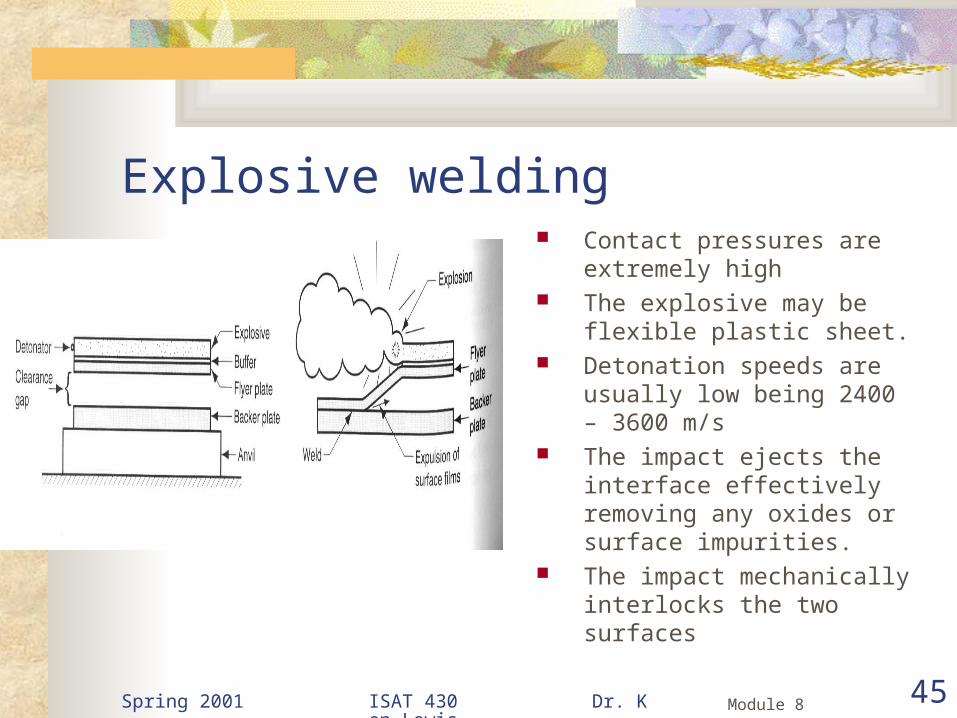
Explosive welding Contact pressures are extremely
high The explosive may be flexible
plastic sheet. Detonation speeds are usually low
being 2400 – 3600 m/s The impact ejects the interface
effectively removing any oxides or surface impurities.
The impact mechanically interlocks the two surfaces

Spring 2001 ISAT 430 Dr. Ken Lewis 46Module 8
Explosion Welding

Spring 2001 ISAT 430 Dr. Ken Lewis 47Module 8
Explosive Welding Pieces of up to 20ft x 7 ft have been joined Very useful in cladding work
Cladding tantalum (Ta) to ordinary steel gives the inertness of Ta with the economy of steel.
Requires well trained personnel.

Brazing and Soldering

Spring 2001 ISAT 430 Dr. Ken Lewis 49Module 8
Brazing A process which a filler metal is placed at or between
the faying surfaces, the temperature is raised high enough to melt the filler metal but not the base metal. The molten metal fills the spaces by capillary
attraction. Two types
Ordinary brazing (above) Braze welding (similar to oxy-welding)
Faying surfaces = the surfaces to be joined.

Spring 2001 ISAT 430 Dr. Ken Lewis 50Module 8
Filler Metals for BrazingBase Metal Filler Metal Brazing Temperature
°C
Aluminum & its alloys Aluminum – silicon 570 – 620
Magnesium alloys Magnesium – aluminum
580 – 625
Copper & its alloys Copper – phosphorus 700 – 925
Ferrous and Non-ferrous (except Al,
Mg)
Ag & Cu alloys, copper phosphorus
620 – 1150
Fe, Ni, Co base alloys Gold 900 – 1100
Stainless steels, Ni, Co alloys
Nickel - Silver 925 – 1200
Spring 2001 ISAT 430 Dr. Ken Lewis 51Module 8
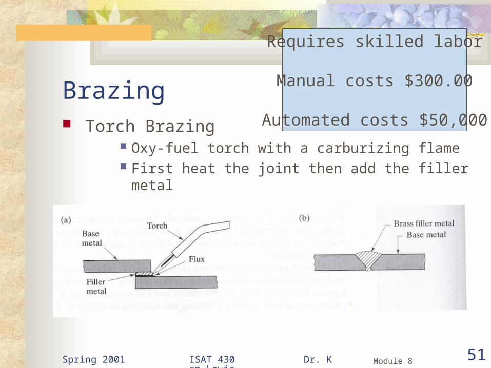
Brazing Torch Brazing
Oxy-fuel torch with a carburizing flame First heat the joint then add the filler metal
Requires skilled labor
Manual costs $300.00
Automated costs $50,000

Spring 2001 ISAT 430 Dr. Ken Lewis 52Module 8
Furnace Brazing Pre-cleaned and preloaded
with brazing metal The filler metal is a
shaped wire Vacuum or neutral
atmosphere furnaces are used for active metals
Note the completeness of the joint.

Spring 2001 ISAT 430 Dr. Ken Lewis 53Module 8
Brazing Capabilities Typical joints
Dissimilar metals can be assembled with good joint strength.
Shear strength can reach 120 ksi (800 MPa) using alloys containing silver.
Concerns Clearance too small,
metal will not penetrate Clearance to big,
insufficient capillary attraction.

Soldering

Spring 2001 ISAT 430 Dr. Ken Lewis 55Module 8
Soldering Solders (Latin solidare make solid) melt at a
temperature that his the melting point of the eutectic
Traditionally have been tin / lead
Others now are used. Pb is toxic and environmentally unfriendly

Spring 2001 ISAT 430 Dr. Ken Lewis 56Module 8
SoldersTin – Lead General purpose
Tin – Zinc Aluminum
Lead – Silver Strength at higher than room temperature
Cadmium – Silver Strength at high temperatures
Zinc – Aluminum Aluminum, corrosion resistance
Tin – Silver Electronics
Tin – Bismuth Electronics
Spring 2001 ISAT 430 Dr. Ken Lewis 57Module 8
Soldering Used extensively in the electronics industry Soldering temperatures are low Not used in load bearing members Butt joints rarely made If strength is needed, the joint may be mechanically
interlocked

Spring 2001 ISAT 430 Dr. Ken Lewis 58Module 8
Solder joints Typical joints Note that the starred
examples are mechanically joined first.
Copper and silver are easy
Fe, Al hard to solder because of their tough oxide films.

Adhesive Joints

Spring 2001 ISAT 430 Dr. Ken Lewis 60Module 8
Adhesive Bonding Joining process whereby a filler material is used to
hold two closely spaced parts together by surface attachment
Filler material (adhesive) Usually non-metal Usually a polymer
Curing Process (usually chemical) whereby the adhesive
physical properties are changed from a liquid to a solid.

Spring 2001 ISAT 430 Dr. Ken Lewis 61Module 8
Adhesive bonding Used in antiquity
Egyptians used gum Romans used pine tar to caulk their ships Glues were made from cheese, animal hooves, stag
horns for construction Plywood
Invented in 1905 Wood bonded with a phenol – formaldehyde resin

Spring 2001 ISAT 430 Dr. Ken Lewis 62Module 8
Adhesive systems

Spring 2001 ISAT 430 Dr. Ken Lewis 63Module 8
General Properties of some adhesives Acrylic
Thermoplastic, quick setting, tough bond at r.t.
Tennis racquets, metal parts
Epoxy Thermoset, strongest
engineering adhesive Metal, ceramic, rigid
plastic parts
Cyanoacrylate Thermoplastic, touch “Crazy Glue”
Hot Melt Thermoplastic, quick
setting, easy to apply Bonds most anything – Packaging, book
binding, metal can joints

Spring 2001 ISAT 430 Dr. Ken Lewis 64Module 8
General Properties of some adhesives Phenolic
Thermoset, strong, brittle Brake lining, clutch
pads, honeycomb structures
Silicone Thermoset, slow curing,
flexible, rubber like Gaskets sealants
Water base Animal Vegetable Rubbers
Inexpensive, non-toxic Wood, paper, fabric Leather, dry seal
envelopes

Spring 2001 ISAT 430 Dr. Ken Lewis 65Module 8
Joint Design Usually not as strong as welding or brazing joints Design principles
Maximize joint contact area Joints are strongest in shear and or tension so joints
should be designed to accommodate this Joints are weakest in cleavage or peel. Avoid these
stresses

Spring 2001 ISAT 430 Dr. Ken Lewis 66Module 8
Joint Peel
Brittle Tough

Spring 2001 ISAT 430 Dr. Ken Lewis 67Module 8
Buttjoints
Tjoints
Cornerjoints
Acceptable Joints
Spring 2001 ISAT 430 Dr. Ken Lewis 68Module 8
Adhesive bonding Advantages It provides a surface bond It distributes the load at the interface
Eliminates high stress areas caused by bolts, etc. Very thin and fragile components can be bonded without
significant increase in weight. Usually a near ambient temperature bond so distortion is
eliminated. Some adhesives are flexible after bonding Sealing as well as bonding can be achieved Joint design is often simplified

Spring 2001 ISAT 430 Dr. Ken Lewis 69Module 8
Adhesive bonding Disadvantages Joints are not as strong Adhesive must be compatible with materials being
joined Service temperatures are limited Cleanliness and surface preparation prior to adhesive
application are important Curing times can impose a limit on production rates Inspection of the bonded joint is limited.