material and thickness grading for aeroelastic tailoring ... · pdf filefirst, they enable ......
TRANSCRIPT
httpsntrsnasagovsearchjspR=20140012776 2018-01-24T192326+0000Z
NASATMndash2014-218516
Material and Thickness Grading for Aeroelastic Tailoring of the Common Research Model Wing Box
Bret K Stanford Langley Research Center Hampton Virginia
Christine V Jutte Craig Technologies Inc Cape Canaveral Florida
September 2014
NASA STI Program in Profile
Since its founding NASA has been dedicated to the advancement of aeronautics and space science The NASA scientific and technical information (STI) program plays a key part in helping NASA maintain this important role
The NASA STI program operates under the auspices of the Agency Chief Information Officer It collects organizes provides for archiving and disseminates NASArsquos STI The NASA STI program provides access to the NASA Aeronautics and Space Database and its public interface the NASA Technical Report Server thus providing one of the largest collections of aeronautical and space science STI in the world Results are published in both non-NASA channels and by NASA in the NASA STI Report Series which includes the following report types
bull TECHNICAL PUBLICATION Reports of completed research or a major significant phase of research that present the results of NASA Programs and include extensive data or theoretical analysis Includes compilations of significant scientific and technical data and information deemed to be of continuing reference value NASA counterpart of peer-reviewed formal professional papers but having less stringent limitations on manuscript length and extent of graphic presentations
bull TECHNICAL MEMORANDUM Scientific and technical findings that are preliminary or of specialized interest eg quick release reports working papers and bibliographies that contain minimal annotation Does not contain extensive analysis
bull CONTRACTOR REPORT Scientific and technical findings by NASA-sponsored contractors and grantees
bull CONFERENCE PUBLICATION Collected papers from scientific and technical conferences symposia seminars or other meetings sponsored or co-sponsored by NASA
bull SPECIAL PUBLICATION Scientific technical or historical information from NASA programs projects and missions often concerned with subjects having substantial public interest
bull TECHNICAL TRANSLATION English-language translations of foreign scientific and technical material pertinent to NASArsquos mission
Specialized services also include organizing and publishing research results distributing specialized research announcements and feeds providing information desk and personal search support and enabling data exchange services
For more information about the NASA STI program see the following
bull Access the NASA STI program home page at httpwwwstinasagov
bull E-mail your question to helpstinasagov
bull Fax your question to the NASA STI Information Desk at 443-757-5803
bull Phone the NASA STI Information Desk at 443-757-5802
bull Write to STI Information Desk
NASA Center for AeroSpace Information 7115 Standard Drive
Hanover MD 21076-1320
NASATMndash2014-218516
Material and Thickness Grading for Aeroelastic Tailoring of the Common Research Model Wing Box
Bret K Stanford Langley Research Center Hampton Virginia
Christine V Jutte Craig Technologies Inc Cape Canaveral Florida
National Aeronautics and Space Administration
Langley Research Center Hampton Virginia 23681-2199
September 2014
Available from
NASA Center for AeroSpace Information 7115 Standard Drive
Hanover MD 21076-1320 443-757-5802
Material and Thickness Grading for Aeroelastic Tailoring of the Common Research Model Wing Box
Bret K Stanford NASA Langley Research Center Hampton VA 23681
Christine V Jutte Craig Technologies Inc Cape Canaveral FL 32920
This work quantifies the potential aeroelastic benefits of tailoring a full-scale wing box structure using tailored thickness distributions material distributions or both simultaneously These tailoring schemes are considered for the wing skins the spars and the ribs Material grading utilizes a spatially-continuous blend of two metals Al and Al+SiC Thicknesses and material fraction variables are specified at the 4 corners of the wing box and a bilinear interpolation is used to compute these parameters for the interior of the planform Pareto fronts detailing the conflict between static aeroelastic stresses and dynamic flutter boundaries are computed with a genetic algorithm In some cases a true material grading is found to be superior to a single-material structure
I Introduction One potential enabling technology for wing structures is functionally graded materials (FGM) which have not
(to the best of the authorsrsquo knowledge) received much attention for aeroelastic tailoring Functionally graded materials have continuously varying properties by spatially varying the distribution of two (or more) materials which facilitates designs with tailored stiffness within a continuous metallic structure [1] New manufacturing processes such as electron beam freeform fabrication (EBF3 an additive manufacturing process) [2] are helping to enable the fabrication of functionally graded metals and making FGMs accessible to aircraft design
FGMs offer two potentially advantageous design capabilities First they enable continuous changes in material properties (elastic modulus density yield stress etc) throughout a structure local properties can be tuned Second they enable changes in structural stiffness without necessarily requiring a geometric change in the structure such as an increase in thickness An FGM may be numerically realized by identifying two materials and then specifying the spatial distribution of material fraction (any continuous value between zero which is 100 of material A and unity which is 100 of material B) by which the local material properties can be tuned within the wing structure In conventional aircraft structures stiffness can be increased using larger material thicknesses which will add mass as well An FGM composed of two materials with very similar density but different elastic moduli enables the distribution of stiffness to be tailored without affecting the mass distribution This allows for designs with stiffness and mass distributions that would not be possible with conventional materials Additionally material and geometric changes in a structure have different effects on the stiffness For example the flexural rigidity of a plate is proportional to its thickness cubed but varies linearly with elastic modulus
Much of the literature pertaining to FGM in an aerospace setting is confined to the panel level In particular most of the existing work details the use of FGM for elastic panels subject to supersonic flows (and thus aerodynamic heating) see Ref [3] for a review of this work Material grading is beneficial to high-temperature applications as it eliminates discrete changes in the coefficient of thermal expansion which can lead to stress concentrations at material boundaries Aerothermoelastic panel flutter boundaries have been shown to benefit as well Despite the potential of FGMs to improve the structural performance of subsonic wings [4] very little work has been done Librescu and Maalawi [5] use material grading to optimize the material distribution of a cantilevered subsonic wing (maximization of torsional divergence under a mass constraint) Linear parabolic and piecewise material grading distributions along the wing span are all considered Though this paper uses fiber volume fractions of composite materials (rather than the metallic grading studied here) it is notable as one of very few papers that considers subsonic aeroelastic tailoring via material grading
An important benchmark comparison is between the possible aeroelastic benefits of a) material grading (between two materials that may or may not have the same density) and b) those found for traditional thickness
grading Both studies particularly the latter must be formulated to maintain a constant wing weight and thus provide a fair comparison between the two Given that the impact of thickness is stronger than that of modulus on the local stiffness it may be found that for many situations traditional thickness grading outperforms FGMs despite the weight penalty Furthermore many situations may be found where the best configuration is that which uses 100 of the stiffer material throughout the entire wing structure This is a trivial result this work seeks design scenarios which can be improved with a spatial grading of material
Beyond the comparison between thickness and material grading results will also be shown where both parameter types are varied simultaneously A particularly interesting scenario is one where the thickness grading strategies are found to differ substantially between thickness-only tailoring (with a fixed-material configuration) and simultaneous thickness and material grading These exercises are demonstrated on an all-metallic fully-populated wing box structure (within the Common Research Model (CRM) wing concept [6] a full-scale subsonic transport aircraft wing design) This model consists of wing skins an orthogonal grid of primary rib and spar structures as well as secondary stringer and rib-stiffened structures An aeroelastic framework is developed to compute the static aeroelastic response and the dynamic aeroelastic flutter boundary of a given wing structure This tool is used to demonstrate thickness and material tailoring for the wing skins (section VI) the spars (section VII) and the ribs (section VIII) of the CRM structure
II Wing Box Structure Description The CRM model used here is a full-scale wing design with span of 1928 ft an aspect ratio of nine a taper ratio
of 0275 a leading edge sweep angle of 35deg and a break (crank) along the trailing edge at 37 of the semi-span [6] The wing box lies between 10 and 70 of the local chord The internal support structure is shown in Figure 1 and consists of full-depth spars at the box leading edge trailing edge and one-third of the distance between the two Thirty-seven straight ribs are evenly distributed from root to tip each aligned with the airflow Seven pairs of stringers (one on each skin) travel from root to tip two pairs are evenly distributed between the leading edge spar and the inner spar and five pairs between the inner and trailing edge spar These stringers have a rectangular cross section with a depth of 295 inches and a thickness of 018 inches A full-depth rib stiffener exists at each stringer-rib intersection each with a depth of 264 inches and a thickness of 018 inches The wing box geometry is populated with triangular shell finite elements
Figure 1 Baseline CRM structure used for tailoring studies contour indicates local shell thickness (inches)
The baseline thickness distribution is seen in Figure 1 and aluminum (2024-T3 alloy) is used throughout Stringers and rib stiffeners are modeled with beam elements and the displacement degrees-of-freedom of all nodes at the wing-root of Figure 1 are fixed to zero The inertial impact of leading and trailing edge control effectors are modeled as lumped masses connected to the leading and trailing edge spars via un-weighted interpolation elements Six 320 lb masses are used along the inboard leading edge and three additional masses of 240 lbs outboard Similarly six 840 lb masses and three 140 lb masses are used along the trailing edge These mass values were calculated by scaling data from a similar commercial transport
2
III Aeroelastic Modeling Tools The static aeroelastic analysis and flutter analysis is conducted in NASTRAN MATLAB scripts generate input
files for the analyses and extract the data from the output files to compare performance metrics and assess the aeroelastic tailoring concepts Flat-plate aerodynamic paneling is utilized for both steady and unsteady air loads with a 10times10 mesh of boxes for the inboard section of the wing and a 10times40 mesh outboard Finite element nodes located at intersections of the upper skins and ribs or the upper skins and spars are used to interpolate between the structural and aerodynamic meshes
Static aeroelastic wing deformation is computed at an angle of attack of 6deg a Mach number of 085 and an altitude of 35 kft The resulting data set is distilled into an aggregate stress metric (the Kreisselmeier-Steinhauser (KS) function [7]) where low values are desirable (ie indicative of low overall stress values) The flexural axis of the wing [8] and the line of centers of gravity from root to tip are also computed A flutter analysis (p-k method) is then performed with 20 structural dynamic modes at a Mach number of 085 and using the speed of sound at sea level the velocity is computed and fixed The dynamic pressure varies from 0 to 148 psi divided into 250 increments by varying the flow density zero-damping cross-over points indicate flutter
IV Solution Methodology The metallic blend of material used here is a combination of aluminum alloy (Al) and aluminum with silicon
carbide particulates (Al+SiC specifically 6092SiC175p) where the material fraction is specified at every location along the wing The two materials have nearly the same density but Al+SiC has 44 higher modulus and 57 higher yield stress than Al Material fraction variables vary from zero (100 aluminum) to unity (100 Al+SiC) and thickness variables range from a prescribed lower bound of 005 inches to an upper bound of 075 inches These variables are assigned to the four corners of the wing box planform and a bilinear interpolation is used to determine the material and thickness for the interior
Separate tailoring is used for the upper and lower wing skins resulting in 16 total variables The same interpolation functions can be used for the three spars where the thickness and material properties for each member are constant through the depth of the wing box resulting in 8 additional design variables The same strategy is used for the ribs adding 8 more variables The total number of variables is 32 though none of the work below engages all of these parameters at once instead separating into skin-only tailoring (section VI) spar-only tailoring (section VII) and rib-only tailoring studies (section VIII) When not being tailored the material and thickness variations are fixed at the same values used in the baseline structure whose thickness distribution is seen in Figure 1 using aluminum throughout (a material fraction of zero) No materialthickness tailoring is considered for the secondary skin stringer and rib stiffener structures
A multi-objective genetic algorithm [9] is used to find the Pareto front between the KS function (where a lower value is desired as it indicates reduced aeroelastic stress levels throughout the wing) and the normalized flutter dynamic pressure (where a higher value is desired providing a greater margin between the cruise dynamic pressure and the flutter boundary) The algorithm is forced to satisfy a weight equality constraint such that all designs across the Pareto fronts have the same weight as the baseline structure For material-only grading this is automatically satisfied (as the density of Al and Al+SiC is the same) but the thickness grading design space is obviously restricted by this constraint
V Pareto Fronts The results in the remainder of this paper make changes to the metallic material properties andor the thickness
distribution of the skins ribs and spars The resulting aeroelastic performance is continually referred back to the performance of the all-aluminum baseline structure drawn in Figure 1 For the tailoring of the wing skins three studies are conducted all under a constant wing weight First the material is held fixed as pure aluminum and the thickness design variables are altered to locate the Pareto front Next the thicknesses are held fixed at their baseline values and the material fraction distribution is fed to the GA Finally both thickness and material variables are allowed to change simultaneously This process is repeated for the spars and again for the ribs resulting in 9 total Pareto fronts as seen in Figure 2
The performance of the baseline design is also provided in Figure 2 and all flutter results are normalized to this value Tailoring of the wing skins clearly has the biggest impact upon the aeroelastic performance due to the large acreage of these structures Of course the size of these skin structures also makes them the least amenable to continuous thickness and (especially) material grading in terms of current state-of-the-art manufacturing limitations and so their performance improvements shown in Figure 2 may be restricted to some degree Contrastingly spar tailoring is more limited in terms of its ability to impact the aeroelastic performance beyond the baseline
3
performance but is also more tractable in terms of manufacturability This trade-off is also true for rib tailoring though performance improvements are very moderate in this case The next three sections describe the structures that compromise these Pareto fronts in more detail
Figure 2 Pareto fronts between aeroelastic flutter and strength for various tailoring strategies all designs have the same weight as the baseline structure
VI Thickness and Material Tailoring of Wing Skins The Pareto front in Figure 2 with thickness tailoring of the wing skins only (their material is fixed as aluminum)
is discussed first The migration of thickness design variables across the front is plotted in Figure 3 Specifically the data is plotted versus the KS function with the implicit understanding that as the KS function gets larger (deteriorates) the un-plotted flutter performance becomes larger (improves) as dictated by the conflict between the two metrics As noted above the GA must allocate the thickness distribution such that the total wing weight is constant (and equal to that of the baseline structure) and so the thickness in a given portion of the wing skin can only be increased at the expense of another location These distributions for four selected locations along the front (the two extremes as well as two intermediate positions) are shown in Figure 4
In general peak thickness begins at the leading edge of the root for designs with low static aeroelastic stresses shifts towards the root trailing edge and finally to the leading edge of the wing tip for designs with improved flutter performance This is indicative of the general trade-off between static and dynamic aeroelastic phenomena as only the latter will be strongly affected by (and see any improvement due to) added material at the wing tip As seen in Figure 3 desired increases in the leading edge tip must be offset by a reduction in thickness at the leading edge root in order to preserve the constant wing weight Once this latter variable reaches the lower bound (005 inches) material is removed from the trailing edge root The trailing edge tip thickness never leaves this lower bound and none of the variables approach the allowed upper bound of 075 inches For the lowest stress design (left-most extreme of the Pareto front) high thickness at the leading edge root is clearly valued but the other design variables are already near the lower bound Additional thickness at the root cannot be obtained without either violating this lower bound (which would soon lead to non-physical negative thickness values) or violating the constant weight constraint A similar conflict is seen at the opposite end of the front where high thickness is desired at the leading edge tip but ultimately unable to reach the upper bound due to these restrictions
4
Even though the genetic algorithm is given the opportunity to tailor the upper and lower skins separately the two distributions as seen in Figure 4 are fairly similar Moderately higher thicknesses are seen in the lower skins at the two critical locations (leading edge root for low-stress configurations leading edge tip for high-flutter) but the overall trends between the two surfaces are nearly mirrored
Figure 3 Skin thickness design variables across the Pareto front of Figure 2 without material tailoring
Figure 4 Skin thickness distribution for select designs across the Pareto front of Figure 2 without material tailoring
Flutter behavior for the two extreme designs in Figure 4 is shown in Figure 5 (lowest flutter point) and Figure 6 (highest flutter point) Qualitatively the two flutter mechanisms are very similar with the latterrsquos destabilization boundary (normalized dynamic pressure of 1436) moderately larger than the other (0870) A first bending mode (1B) second bending mode (2B) third bending mode (3B) edgewise bending mode (1E) torsion mode (1T) and an aerodynamic lag root are all seen where the advent of the latter leads to various mode tracking and dropping issues within NASTRANrsquos algorithm logic The second bending mode is the root which ultimately flutters in these two
5
figures it is not unusual for wings with higher aspect ratios to experience a 2B-1T flutter mechanism [10] due to the proximity of those two natural frequencies
It can also be seen that NASTRAN is unable to correctly track the second bending mode through the flutter point in Figure 5 and instead shows the edgewise bending mode destabilizing The reason for this is unclear but does not seem to degrade the accuracy of the flutter boundary It may be related to the fact that the dihedral of the CRM wing produces an edgewise bending mode with a moderate amount of out-of-plane deflection and this latter motion can interact with the unsteady airloads It is also seen that the lag root in Figure 5 occurs at nearly the same dynamic pressure as the flutter point perhaps adding to the complications of NASTRANrsquos tracking procedure This mode switching mistake is not seen in Figure 6 as the 2B mode cleanly crosses the 1E mode at the flutter point
Figure 5 Eigenvalue migration for the design with the worst flutter boundary in Figure 4
Figure 6 Eigenvalue migration for the design with the best flutter boundary in Figure 4
Von Mises failure indices are shown in Figure 7 for the two extremes of the Pareto front as well as the deformed configurations for each Because material grading is not used in this case (both wings are entirely aluminum) the yield stress is not a spatial function over the wing and so the von Mises stress is directly proportional to the failure index contours shown in Figure 7 Peak stresses occur in the skins themselves with a high-stress zone at the yehudi break and a sharp stress concentration at the trailing edge of the root Stresses in the ribs are small and the spars show the typical distribution of a structure under bending loads high von Mises stresses in the upper and lower fibers but much smaller through the center (though the mesh density through the depth of the wing is not large enough to accurately capture fine details in this distribution)
Two different strategies may be pursued when tailoring the thickness andor material distribution throughout a structure Thicknesses may be increased at locations in the structure which experience high local stresses such as a concentration Alternatively a global approach may be taken where material is allocated so as to increase the overall stiffness of the structure (or decrease the compliance) thus dropping the stress levels in most locations including the aforementioned local concentration This latter approach is exploited by the GA for the results in
6
Figure 7 despite the large stresses at the yehudi break and the root trailing edge material in the lowest-stress design of Figure 4 (which corresponds to the stresses on the left of Figure 7) is solely allocated at the leading edge root Owing to the swept-back nature of the wing this location has the greatest impact on the global stiffness of the wing Adding material here decreases the overall deformation levels of the elastic wing dropping the stress throughout including the two critical areas
Figure 7 Failure indices (color bar) and deformed configurations for the extreme cases in Figure 4
It may be found that the use of higher-order tailoring methods (beyond the simple bilinear shape functions used here a more localized method for example) may prompt the GA to make use of both global and local strategies but this will have to be assessed in future work The conservatism of the KS function is also noted in Figure 7 where both values are greater than one which would indicate an elastic failure The true stress distribution throughout the finite element mesh for the left plot of Figure 7 at least is actually entirely below the failure threshold and all local failure indices are less than unity Regardless for this work less emphasis is placed on absolute performance values (either the KS value the peak failure index through the wing or even the flutter point) in favor of deltas between two designs which are clearly demonstrated in the above figures
Additional insight into the underlying physics and trade-offs of Figure 3 may be seen in the movement of the flexural axis and the center of gravity of the wing structures which is given in Figure 8 As before data is plotted versus the KS function only with the implicit understanding that the flutter metric will improve as KS deteriorates The left plot of Figure 8 measures the center of gravity at the wing tip as well as the chordwise location at the wing tip about which a transverse force can be applied without a subsequent change in the tip angle of attack (the flexural axis as described in [8]) Both metrics are plotted as a sweep angle where values closer to zero move away from the aft swept wing It is seen that as the stresses in the wing (and hence the flight loads) decrease as both axes are swept towards the wingrsquos leading edge and the opposite is true for flutter improvements The flutter trends follow the expected pattern where moving material forward (pushing the CG towards the leading edge) is well-known to have a beneficial effect upon flutter speed [11]
The flexural axis trends in Figure 8 however do not follow the expected pattern pushing the flexural axis farther away from the wingrsquos leading edge should increase the negative bend-twist coupling (increase the adaptive wash-out) further alleviating the flight loads The opposite trend seen here may result from several factors First the stress-reduction trend in Figure 3 may not be a true aeroelastic tailoring effect (ie may not be predicated on coupled bend-twist deformations) as opposed to a simple desire to globally stiffen the wing Secondly it is clear from the left-most plot of Figure 4 that stiffness at the root is allocated towards the leading edge which should have the intended effect of pushing the local flexural axis forward as well thus augmenting the wash-out It may be found that plotting the curve of flexural axes from root to tip would indicate a rearward shift for the tip (already plotted in Figure 8) and a forward shift for the root (where local stiffness is more important) Such a curve is easily computed for the CG metric (right plot of Figure 8) which does show opposite trends from root to tip The CG of the root and the entire wing moves rearward but the CG at the tip (where local inertia is more important) moves in the expected forward direction for flutter improvements CG movement at the tip is more moderate than the root simply because there is less material at the tip of a tapered wing
7
Figure 8 Flexural axis and the center of gravity movement corresponding to the data of Figure 3
Details concerning the change in the uncoupled vibration frequencies of the structures along the Pareto front are given in Figure 9 now plotted as a function of the flutter dynamic pressure (as opposed to the KS function which is not explicitly impacted by the vibration modes) As noted above the improvement in flutter behavior as one moves along the Pareto front is driven by the addition of material at the leading edge tip This is accompanied by an expected drop in the first bending and edgewise modes and an increase in the first torsion second bending and third bending modes (the trend reverses towards the peak flutter speeds likely due to the thickness reversal of the trailing edge root in Figure 3) An increased separation between the natural vibration frequencies of the two modes which ultimately coalesce to form a flutter mechanism (2B and 1T in Figure 5 and Figure 6) will delay the onset of that mechanism [11] The strong correlation between this separation and the flutter dynamic pressure is clearly seen in Figure 9
Figure 9 Uncoupled vibration frequencies corresponding to the data of Figure 3
Next the thickness distribution of the skins is held constant (equal to the baseline value shown in Figure 1) and the material fraction variables at the four corners of the upper and lower skins are allowed to change The resulting Pareto front is shown in Figure 2 and has devolved into a single point there is no conflict between static aeroelastic stresses and dynamic flutter behavior for this design space An examination of the material design variables at this Pareto point reveals that they have all been forced to unity The optimal structure is made entirely of the stiffer of the two materials Al+SiC
This is a trivial answer of course in the sense that it is usually expected for an increase in stiffness with no associated weight penalty (as the density of the two materials is considered identical) to have a favorable impact on many aero-structural metrics The true goal of this study is to identify situations where spatial material grading may be used where a structure may benefit from a localized reduction in the stiffnessmodulus but this is not observed for the current case
8
The next step is to allow the genetic algorithm to change both the material distribution and the thickness distribution simultaneously for both the upper and lower skins (resulting in 16 total design variables the corner control points governing the bilinear shape functions) The resulting Pareto front is also given in Figure 2 and shows a clear and substantial improvement over the thickness-only Pareto front discussed above a 98 drop in the lowest KS value and a near-doubling of the best flutter speed Every design on this Pareto front dominates every design on the thickness-only front in terms of both objectives As before however an inspection of the material design variables reveals that each has been pushed to the upper limit of unity each of these structures is entirely composed of the stiffer Al+SiC material Only thickness variations are used to form the Pareto front and the trends of each thickness variable (seen in Figure 10) are very similar to those seen in Figure 3 where the weaker Al material was used For this wing configuration and this material combination functionally graded materials in the wing skins is not found to provide any benefit
Figure 10 Skin thickness design variables across the Pareto front with material tailoring included
VII Thickness and Material Tailoring of Wing Spars The above exercise is repeated for the wing spars holding the material and thickness distribution of the skins
equal to that of the baseline structure Considering first the case when only the spar thickness distribution is varied (and the material fraction is held at zero Al) the Pareto front is shown in Figure 2 As noted the performance improvements available from this study are far less than what could theoretically be obtained from tailoring the wing skins but tailoring of a spar (or rib or stringer) is perhaps more feasible given the current manufacturing state-ofshythe-art The four thickness design variables along the Pareto front are shown in Figure 11 as well as three contour plots at select locations (the two extremes and one intermediate design) For the design with the best aeroelastic strength both leading edge design variables are nearly equal to the upper bound of 075 inches and both trailing edge points are nearly equal to the lower bound of 005 It is noted that for the previous wing skin tailoring study it was impossible for any of the thickness variables to approach this upper bound (even if the other 3 variables were set to the lower bound) without violating the constant mass constraint For spar tailoring strictly due to the geometry of the problem it is possible for two variables to reach this upper limit and still retain the required weight (equal to the baseline structure)
As the KS function degrades in Figure 11 (and implicitly the flutter behavior improves) the thickness at the leading edge root monotonically decreases and the trailing edge root increases This rearward shift in root thickness is also noted with the wing skins (Figure 4) though the migration at the trailing edge is ultimately limited (and must reverse its trend) by the weight constraint A significant difference between these spar results and the skin results is an increase in the leading edge tip thickness for improved flutter performance via a forward shift in the CG In
9
Figure 11 this thickness control variable is always at the peak value a behavior which may have been noted in the skins as well had that problem not been limited by the weight constraint Regardless the requisite separation of the bending and torsion modes (to delay the flutter onset) is obtained by decreasing the stiffness of the leading edge spar near the root
Next the thickness of the spars is held constant (equal to the baseline value) and material tailoring is considered Here unlike the previous wing skin problem there is benefit to including a spatial grading between two materials ie each material fraction is not simply set to unity From the Pareto front in Figure 2 it can be seen that material grading can provide a moderate decrease in the KS function though the flutter performance is not improved (and does not vary much within the front itself) This may reflect the fact that the density of the two materials is equal thus removing an important inertia-based tailoring tool for flutter improvements The material fraction design variables are shown in Figure 12 the highest strength design is a uniform Al+SiC material and three of the variables remain nearly equal to this upper limit throughout the entire front A very mild improvement in flutter (from a normalized value of 1044 to 1048) is available by using the weaker Al material at the leading edge root This will decrease the frequency of both the bending and the torsional frequencies but the former drops at a slightly larger rate increasing the separation between the two and hence increasing the flutter margin
Figure 11 Spar thickness design variables across the Pareto front without material tailoring
Figure 12 Spar material fraction design variables across the Pareto front without thickness tailoring
10
Finally both thickness and material parameters are considered simultaneously The resulting Pareto front in Figure 2 shows a leftward shift of the front as compared to the thickness-only behavior the KS function is decreased but flutter behavior is not improved The migration in design variables is shown in Figure 13 and select contour plots are given in Figure 14 Thickness distributions are similar to what was seen above in Figure 11 tip variables remain at the extreme bounds and a rearward shift in thickness is evident at the root (though these variables do not change as much as before) The material distributions on the other hand bear little resemblance to the material-only tailoring of Figure 12 The stiffer Al+SiC is mostly used at the trailing edge root and the leading edge root sees some transition to the weaker material for high flutter speeds as before The preferred material at the wing tip however undergoes substantial changes along the Pareto front This is unexpected due to the non-importance of material stiffness and yield stress at the tip as opposed to inertial quantities
Figure 13 Spar thickness (left) and material fraction (right) design variables across the Pareto front
Significant non-smoothness is also noted in the material data of Figure 13 despite the Pareto front itself (Figure 2) exhibiting adequate smoothness There are two possible reasons for this The first is numerical the genetic algorithm may not have converged to the true Pareto front The large design space (8 total variables) and high computational cost will always cast doubt on the convergence properties of the GA but previous wing skin results with more variables (up to 16) displayed adequate smoothness A second possible reason may be discontinuities in the design space itself The KS function is designed to absorb changes in the critical finite element (ie the identification of the element which is mostly highly stressed) in a relatively smooth manner pending the magnitude of a tuning parameter Discontinuities in the flutter mechanism are also possible though bulk changes (the advent of a hump mode or a switch in the coupling mechanism from 1B-1T to 2B-1T) is not observed in the flutter response across the Pareto front Of course even mild discontinuities if present could slow convergence of the GA as well
VIII Thickness and Material Tailoring of Wing Ribs This paper concludes with a presentation of results for tailoring of the wing ribs As seen in Figure 2 while
both spatial thickness and material tailoring can improve the aeroelastic performance over the baseline structure the improvements are very moderate This is because rib structures are not asked to bear significant bending or torsional loads as opposed to wing skins and spars one of their significant functions is to maintain the airfoil shape of the outer mold line [12] a performance metric which is not captured here When thickness-only tailoring is used the Pareto front devolves to a single point whose design is seen in Figure 15 three thickness variables are set to the lower bound of 005 inches and (in order to satisfy the constant weight constraint) the leading edge tip is set to 05 inches This forward-mass design has obvious advantages from a flutter perspective (a 108 increase over the baseline design) and presumably has no detrimental impact on the stress distribution
Next thickness is held constant and material grading is used the resulting design variables are seen in the left column of Figure 16 From Figure 2 it can be seen that the loss of any parameters which can explicitly affect the inertial quantities of the wing drops the flutter speed significantly The worst-performing flutter design coincides
11
with the baseline performance and additional material grading only improve the flutter by 32 Each material variable monotonically increases across this front until it reaches the upper bound with 100 Al for the design with the lowest stress (a non-intuitive result) and 100 Al+SiC for that with the highest flutter speed Finally both material and thickness tailoring parameters are considered simultaneously shown on the right of Figure 16 The thickness-only tailoring result of Figure 15 is technically a member of this Pareto front (ie it is non-dominated) but the GA is unable to find a continuous set of designs between it and the rest of the front and so it is omitted from the data of Figure 16
Figure 14 Spar thickness (left) and material fraction (right) distributions for select designs in Figure 13
Figure 15 Optimal rib thickness distribution without material grading
The result when both thickness and material are graded is a combination of the previous two results Thickness remains set at the distribution in Figure 15 across the entire Pareto front Whereas the material-only grading found some benefit to using the weaker material along the leading edge for low-stress wing structures (before switching over to the stiffer material) the stiffer material is used for every design in this case Trailing edge trends are the same though weaker and less impacted by the upper and lower bounds An 118 peak improvement in flutter is ultimately available over the baseline with a trivial reduction in stress As may be expected the main utility in rib tailoring is inertia-based for flutter improvements Even the design of Figure 15 however may be too thin in certain locations to withstand crushing (Brazier) loads [12] or to adequately maintain the outer mold line of the flexible wing surface and so the moderate demonstrated benefits may be negated by these (un-modeled) metrics
12
Figure 16 Rib material distributions along the Pareto front when thickness is (right) and is not (left) tailored as well
IX Conclusions This paper investigates the use of material grading and thickness grading for aeroelastic tailoring of the
Common Research Model wing box design concept The shell thickness and material fraction (continuously varying between 100 Al and 100 Al+SiC) is tailored throughout the skins spars and ribs Both types of design parameters use a simple bilinear grading strategy across the wing planform (no grading through the depth of the structure) A multi-objective genetic algorithm is used to explore the ensuing design space where the optimal trade-off curve (Pareto front) between two conflicting metrics is of interest static aeroelastic stresses and dynamic aeroelastic flutter
A substantial improvement in both flutter behavior and aeroelastic strength can be obtained by tailoring the thickness distribution of the wing skins (while keeping the total wing mass constant to that of the baseline value) High-strength designs generally allocate material at the leading edge root while high-performing flutter designs utilize material at the leading edge tip The former is a stiffness effect and the latter an inertial effect specifically seeking to move the center of gravity of the wing forward For this study there does not appear to be a strong incentive to tailor the upper and lower skins separately as the thickness variables largely mirror one another across the entire Pareto front
When the thickness is held constant and the material fraction of the wing skins is optimized the Pareto front devolves into a single point which uses 100 of the stiffer Al+SiC material in other words material grading offers no incentive A similar result is obtained when both thickness and material fractions are tailored simultaneously as each design uses only Al+SiC The thickness trends across the Pareto front are very similar to those found with the thickness-only tailoring (which was restricted to 100 Al) and so within the skins there is a weak dependence of the elastic modulus and yield strength upon the best thickness tailoring schemes
13
Additional studies explore the use of FGM and thickness tailoring for spars and ribs holding the properties of the skins constant These latter studies do not have as large an impact on the aeroelastic physics as the skins do but are perhaps more feasibly obtained from a manufacturing perspective Spar structures benefit from thickness tailoring and (unlike the wing skins) from material tailoring as well finding benefit to using some amount of the weaker Al alloy material (for high-flutter designs only) When both thickness and material grading is used simultaneously thickness trends mirror the previous spar results though the material trends do not Rib tailoring has the smallest impact on the structural behavior Its impact is mainly via changes in the inertial distribution affecting flutter resistance This involves adding as much material as possible to the leading edge wingtip and (to satisfy the weight constraint) reducing the thickness everywhere else to the lower bound The resulting improvement is minor and may not even be attainable due to (un-modeled) rib crushing concerns for thin members
Acknowledgements This work is funded by the Fixed Wing project under NASArsquos Fundamental Aeronautics Program
References [1] Miyamoto Y Kaysser W Rabin B Kawasaki A Ford R Functionally Graded Materials Design
Processing and Applications Kluwer Academic Dordrecht The Netherlands 1999 [2] Taminger K Hafley R ldquoElectron Beam Freeform Fabrication A Rapid Metal Deposition Processrdquo
Proceedings of the 3rd Annual Automotive Composites Conference Troy MI September 9-10 2003 [3] Marzocca P Fazelzadeh S Hosseini M ldquoA Review of Nonlinear Aero-Thermo-Elasticity of Functionally
Graded Panelsrdquo Journal of Thermal Stresses Vol 34 pp 536-568 2011 [4] Birman V Byrd L ldquoModeling and Analysis of Functionally Graded Materials and Structuresrdquo Applied
Mechanics Reviews Vol 60 No 5 pp 195-216 2007 [5] Librescu L Maalawi K ldquoMaterial Grading for Improved Aeroelastic Stability in Composite Wingsrdquo
Journal of Mechanics of Materials and Structures Vol 2 No 7 pp 1381-1394 2007 [6] Vassberg J DeHaan M Rivers S Wahls R ldquoDevelopment of a Common Research Model for Applied
CFD Studiesrdquo AIAA Applied Aerodynamics Conference Honolulu HI August 2008 [7] Kreisselmeier G Steinhauser R ldquoSystematic Control Design by Optimizing a Vector Performance Indexrdquo
International Federation of Active Controls Symposium on Computer-Aided Design of Control Systems Zurich Switzerland 1979
[8] Weisshaar T Nam C Batista-Rodriguez A ldquoAeroelastic Tailoring for Improved UAV Performancerdquo AIAA Structures Structural Dynamics and Materials Conference Long Beach CA April 20-23 1998
[9] Deb K Pratap A Agarwal S Meyarivan T ldquoA Fast and Elitist Multiobjective Genetic Algorithmrdquo IEEE Transactions on Evolutionary Computations Vol 6 No 2 pp 182-197 2002
[10] Tang D Dowell E ldquoExperimental and Theoretical Study on Aeroelastic Response of High-Aspect Ratio Wingsrdquo AIAA Journal Vol 39 No 8 pp 1430-1441 2001
[11] Bisplinghoff R Ashley H Halfman R Aeroelasticity Addison-Wesley Cambridge MA 1955 [12] Niu M Airframe Structural Design Conmilit Press Ltd Hong Kong 1988
14
REPORT DOCUMENTATION PAGE Form ApprovedOMB No 0704-0188
The public reporting burden for this collection of information is estimated to average 1 hour per response including the time for reviewing instructions searching existing data sourcesgathering and maintaining the data needed and completing and reviewing the collection of information Send comments regarding this burden estimate or any other aspect of thiscollection of information including suggestions for reducing this burden to Department of Defense Washington Headquarters Services Directorate for Information Operations and Reports (0704-0188) 1215 Jefferson Davis Highway Suite 1204 Arlington VA 22202-4302 Respondents should be aware that notwithstanding any other provision of law no person shall be subject to any penalty for failing to comply with a collection of information if it does not display a currently valid OMB control numberPLEASE DO NOT RETURN YOUR FORM TO THE ABOVE ADDRESS
1 REPORT DATE (DD-MM-YYYY) 01- 09 - 2014
2 REPORT TYPE Technical Memorandum
3 DATES COVERED (From - To)
4 TITLE AND SUBTITLE
Material and Thickness Grading for Aeroelastic Tailoring of the Common Research Model Wing Box
5a CONTRACT NUMBER
5b GRANT NUMBER
5c PROGRAM ELEMENT NUMBER
6 AUTHOR(S)
Stanford Bret K Jutte Christine V
5d PROJECT NUMBER
5e TASK NUMBER
5f WORK UNIT NUMBER
432938110107434008 7 PERFORMING ORGANIZATION NAME(S) AND ADDRESS(ES)
NASA Langley Research Center Hampton VA 23681-2199
8 PERFORMING ORGANIZATION REPORT NUMBER
L-20438
9 SPONSORINGMONITORING AGENCY NAME(S) AND ADDRESS(ES) National Aeronautics and Space Administration Washington DC 20546-0001
10 SPONSORMONITORS ACRONYM(S)
NASA 11 SPONSORMONITORS REPORT
NUMBER(S)
NASATM-2014-218516 12 DISTRIBUTIONAVAILABILITY STATEMENT Unclassified - Unlimited Subject Category 02 Availability NASA CASI (443) 757-5802 13 SUPPLEMENTARY NOTES
14 ABSTRACT
This work quantifies the potential aeroelastic benefits of tailoring a full-scale wing box structure using tailored thickness distributions material distributions or both simultaneously These tailoring schemes are considered for the wing skins the spars and the ribs Material grading utilizes a spatially-continuous blend of two metals Al and Al+SiC Thicknesses and material fraction variables are specified at the 4 corners of the wing box and a bilinear interpolation is used to compute these parameters for the interior of the planform Pareto fronts detailing the conflict between static aeroelastic stresses and dynamic flutter boundaries are computed with a genetic algorithm In some cases a true material grading is found to be superior to a single-material structure
15 SUBJECT TERMS
Aeroelasticity Flutter Metal Mixture Structural members Thickness Wings
16 SECURITY CLASSIFICATION OF 17 LIMITATION OF ABSTRACT
UU
18 NUMBER OF
PAGES
19
19a NAME OF RESPONSIBLE PERSON
STI Help Desk (email helpstinasagov)a REPORT
U
b ABSTRACT
U
c THIS PAGE
U 19b TELEPHONE NUMBER (Include area code)
(443) 757-5802 Standard Form 298 (Rev 8-98)Prescribed by ANSI Std Z3918

Material and Thickness Grading for Aeroelastic Tailoring of the Common Research Model Wing Box
Bret K Stanford NASA Langley Research Center Hampton VA 23681
Christine V Jutte Craig Technologies Inc Cape Canaveral FL 32920
This work quantifies the potential aeroelastic benefits of tailoring a full-scale wing box structure using tailored thickness distributions material distributions or both simultaneously These tailoring schemes are considered for the wing skins the spars and the ribs Material grading utilizes a spatially-continuous blend of two metals Al and Al+SiC Thicknesses and material fraction variables are specified at the 4 corners of the wing box and a bilinear interpolation is used to compute these parameters for the interior of the planform Pareto fronts detailing the conflict between static aeroelastic stresses and dynamic flutter boundaries are computed with a genetic algorithm In some cases a true material grading is found to be superior to a single-material structure
I Introduction One potential enabling technology for wing structures is functionally graded materials (FGM) which have not
(to the best of the authorsrsquo knowledge) received much attention for aeroelastic tailoring Functionally graded materials have continuously varying properties by spatially varying the distribution of two (or more) materials which facilitates designs with tailored stiffness within a continuous metallic structure [1] New manufacturing processes such as electron beam freeform fabrication (EBF3 an additive manufacturing process) [2] are helping to enable the fabrication of functionally graded metals and making FGMs accessible to aircraft design
FGMs offer two potentially advantageous design capabilities First they enable continuous changes in material properties (elastic modulus density yield stress etc) throughout a structure local properties can be tuned Second they enable changes in structural stiffness without necessarily requiring a geometric change in the structure such as an increase in thickness An FGM may be numerically realized by identifying two materials and then specifying the spatial distribution of material fraction (any continuous value between zero which is 100 of material A and unity which is 100 of material B) by which the local material properties can be tuned within the wing structure In conventional aircraft structures stiffness can be increased using larger material thicknesses which will add mass as well An FGM composed of two materials with very similar density but different elastic moduli enables the distribution of stiffness to be tailored without affecting the mass distribution This allows for designs with stiffness and mass distributions that would not be possible with conventional materials Additionally material and geometric changes in a structure have different effects on the stiffness For example the flexural rigidity of a plate is proportional to its thickness cubed but varies linearly with elastic modulus
Much of the literature pertaining to FGM in an aerospace setting is confined to the panel level In particular most of the existing work details the use of FGM for elastic panels subject to supersonic flows (and thus aerodynamic heating) see Ref [3] for a review of this work Material grading is beneficial to high-temperature applications as it eliminates discrete changes in the coefficient of thermal expansion which can lead to stress concentrations at material boundaries Aerothermoelastic panel flutter boundaries have been shown to benefit as well Despite the potential of FGMs to improve the structural performance of subsonic wings [4] very little work has been done Librescu and Maalawi [5] use material grading to optimize the material distribution of a cantilevered subsonic wing (maximization of torsional divergence under a mass constraint) Linear parabolic and piecewise material grading distributions along the wing span are all considered Though this paper uses fiber volume fractions of composite materials (rather than the metallic grading studied here) it is notable as one of very few papers that considers subsonic aeroelastic tailoring via material grading
An important benchmark comparison is between the possible aeroelastic benefits of a) material grading (between two materials that may or may not have the same density) and b) those found for traditional thickness
grading Both studies particularly the latter must be formulated to maintain a constant wing weight and thus provide a fair comparison between the two Given that the impact of thickness is stronger than that of modulus on the local stiffness it may be found that for many situations traditional thickness grading outperforms FGMs despite the weight penalty Furthermore many situations may be found where the best configuration is that which uses 100 of the stiffer material throughout the entire wing structure This is a trivial result this work seeks design scenarios which can be improved with a spatial grading of material
Beyond the comparison between thickness and material grading results will also be shown where both parameter types are varied simultaneously A particularly interesting scenario is one where the thickness grading strategies are found to differ substantially between thickness-only tailoring (with a fixed-material configuration) and simultaneous thickness and material grading These exercises are demonstrated on an all-metallic fully-populated wing box structure (within the Common Research Model (CRM) wing concept [6] a full-scale subsonic transport aircraft wing design) This model consists of wing skins an orthogonal grid of primary rib and spar structures as well as secondary stringer and rib-stiffened structures An aeroelastic framework is developed to compute the static aeroelastic response and the dynamic aeroelastic flutter boundary of a given wing structure This tool is used to demonstrate thickness and material tailoring for the wing skins (section VI) the spars (section VII) and the ribs (section VIII) of the CRM structure
II Wing Box Structure Description The CRM model used here is a full-scale wing design with span of 1928 ft an aspect ratio of nine a taper ratio
of 0275 a leading edge sweep angle of 35deg and a break (crank) along the trailing edge at 37 of the semi-span [6] The wing box lies between 10 and 70 of the local chord The internal support structure is shown in Figure 1 and consists of full-depth spars at the box leading edge trailing edge and one-third of the distance between the two Thirty-seven straight ribs are evenly distributed from root to tip each aligned with the airflow Seven pairs of stringers (one on each skin) travel from root to tip two pairs are evenly distributed between the leading edge spar and the inner spar and five pairs between the inner and trailing edge spar These stringers have a rectangular cross section with a depth of 295 inches and a thickness of 018 inches A full-depth rib stiffener exists at each stringer-rib intersection each with a depth of 264 inches and a thickness of 018 inches The wing box geometry is populated with triangular shell finite elements
Figure 1 Baseline CRM structure used for tailoring studies contour indicates local shell thickness (inches)
The baseline thickness distribution is seen in Figure 1 and aluminum (2024-T3 alloy) is used throughout Stringers and rib stiffeners are modeled with beam elements and the displacement degrees-of-freedom of all nodes at the wing-root of Figure 1 are fixed to zero The inertial impact of leading and trailing edge control effectors are modeled as lumped masses connected to the leading and trailing edge spars via un-weighted interpolation elements Six 320 lb masses are used along the inboard leading edge and three additional masses of 240 lbs outboard Similarly six 840 lb masses and three 140 lb masses are used along the trailing edge These mass values were calculated by scaling data from a similar commercial transport
2
III Aeroelastic Modeling Tools The static aeroelastic analysis and flutter analysis is conducted in NASTRAN MATLAB scripts generate input
files for the analyses and extract the data from the output files to compare performance metrics and assess the aeroelastic tailoring concepts Flat-plate aerodynamic paneling is utilized for both steady and unsteady air loads with a 10times10 mesh of boxes for the inboard section of the wing and a 10times40 mesh outboard Finite element nodes located at intersections of the upper skins and ribs or the upper skins and spars are used to interpolate between the structural and aerodynamic meshes
Static aeroelastic wing deformation is computed at an angle of attack of 6deg a Mach number of 085 and an altitude of 35 kft The resulting data set is distilled into an aggregate stress metric (the Kreisselmeier-Steinhauser (KS) function [7]) where low values are desirable (ie indicative of low overall stress values) The flexural axis of the wing [8] and the line of centers of gravity from root to tip are also computed A flutter analysis (p-k method) is then performed with 20 structural dynamic modes at a Mach number of 085 and using the speed of sound at sea level the velocity is computed and fixed The dynamic pressure varies from 0 to 148 psi divided into 250 increments by varying the flow density zero-damping cross-over points indicate flutter
IV Solution Methodology The metallic blend of material used here is a combination of aluminum alloy (Al) and aluminum with silicon
carbide particulates (Al+SiC specifically 6092SiC175p) where the material fraction is specified at every location along the wing The two materials have nearly the same density but Al+SiC has 44 higher modulus and 57 higher yield stress than Al Material fraction variables vary from zero (100 aluminum) to unity (100 Al+SiC) and thickness variables range from a prescribed lower bound of 005 inches to an upper bound of 075 inches These variables are assigned to the four corners of the wing box planform and a bilinear interpolation is used to determine the material and thickness for the interior
Separate tailoring is used for the upper and lower wing skins resulting in 16 total variables The same interpolation functions can be used for the three spars where the thickness and material properties for each member are constant through the depth of the wing box resulting in 8 additional design variables The same strategy is used for the ribs adding 8 more variables The total number of variables is 32 though none of the work below engages all of these parameters at once instead separating into skin-only tailoring (section VI) spar-only tailoring (section VII) and rib-only tailoring studies (section VIII) When not being tailored the material and thickness variations are fixed at the same values used in the baseline structure whose thickness distribution is seen in Figure 1 using aluminum throughout (a material fraction of zero) No materialthickness tailoring is considered for the secondary skin stringer and rib stiffener structures
A multi-objective genetic algorithm [9] is used to find the Pareto front between the KS function (where a lower value is desired as it indicates reduced aeroelastic stress levels throughout the wing) and the normalized flutter dynamic pressure (where a higher value is desired providing a greater margin between the cruise dynamic pressure and the flutter boundary) The algorithm is forced to satisfy a weight equality constraint such that all designs across the Pareto fronts have the same weight as the baseline structure For material-only grading this is automatically satisfied (as the density of Al and Al+SiC is the same) but the thickness grading design space is obviously restricted by this constraint
V Pareto Fronts The results in the remainder of this paper make changes to the metallic material properties andor the thickness
distribution of the skins ribs and spars The resulting aeroelastic performance is continually referred back to the performance of the all-aluminum baseline structure drawn in Figure 1 For the tailoring of the wing skins three studies are conducted all under a constant wing weight First the material is held fixed as pure aluminum and the thickness design variables are altered to locate the Pareto front Next the thicknesses are held fixed at their baseline values and the material fraction distribution is fed to the GA Finally both thickness and material variables are allowed to change simultaneously This process is repeated for the spars and again for the ribs resulting in 9 total Pareto fronts as seen in Figure 2
The performance of the baseline design is also provided in Figure 2 and all flutter results are normalized to this value Tailoring of the wing skins clearly has the biggest impact upon the aeroelastic performance due to the large acreage of these structures Of course the size of these skin structures also makes them the least amenable to continuous thickness and (especially) material grading in terms of current state-of-the-art manufacturing limitations and so their performance improvements shown in Figure 2 may be restricted to some degree Contrastingly spar tailoring is more limited in terms of its ability to impact the aeroelastic performance beyond the baseline
3
performance but is also more tractable in terms of manufacturability This trade-off is also true for rib tailoring though performance improvements are very moderate in this case The next three sections describe the structures that compromise these Pareto fronts in more detail
Figure 2 Pareto fronts between aeroelastic flutter and strength for various tailoring strategies all designs have the same weight as the baseline structure
VI Thickness and Material Tailoring of Wing Skins The Pareto front in Figure 2 with thickness tailoring of the wing skins only (their material is fixed as aluminum)
is discussed first The migration of thickness design variables across the front is plotted in Figure 3 Specifically the data is plotted versus the KS function with the implicit understanding that as the KS function gets larger (deteriorates) the un-plotted flutter performance becomes larger (improves) as dictated by the conflict between the two metrics As noted above the GA must allocate the thickness distribution such that the total wing weight is constant (and equal to that of the baseline structure) and so the thickness in a given portion of the wing skin can only be increased at the expense of another location These distributions for four selected locations along the front (the two extremes as well as two intermediate positions) are shown in Figure 4
In general peak thickness begins at the leading edge of the root for designs with low static aeroelastic stresses shifts towards the root trailing edge and finally to the leading edge of the wing tip for designs with improved flutter performance This is indicative of the general trade-off between static and dynamic aeroelastic phenomena as only the latter will be strongly affected by (and see any improvement due to) added material at the wing tip As seen in Figure 3 desired increases in the leading edge tip must be offset by a reduction in thickness at the leading edge root in order to preserve the constant wing weight Once this latter variable reaches the lower bound (005 inches) material is removed from the trailing edge root The trailing edge tip thickness never leaves this lower bound and none of the variables approach the allowed upper bound of 075 inches For the lowest stress design (left-most extreme of the Pareto front) high thickness at the leading edge root is clearly valued but the other design variables are already near the lower bound Additional thickness at the root cannot be obtained without either violating this lower bound (which would soon lead to non-physical negative thickness values) or violating the constant weight constraint A similar conflict is seen at the opposite end of the front where high thickness is desired at the leading edge tip but ultimately unable to reach the upper bound due to these restrictions
4
Even though the genetic algorithm is given the opportunity to tailor the upper and lower skins separately the two distributions as seen in Figure 4 are fairly similar Moderately higher thicknesses are seen in the lower skins at the two critical locations (leading edge root for low-stress configurations leading edge tip for high-flutter) but the overall trends between the two surfaces are nearly mirrored
Figure 3 Skin thickness design variables across the Pareto front of Figure 2 without material tailoring
Figure 4 Skin thickness distribution for select designs across the Pareto front of Figure 2 without material tailoring
Flutter behavior for the two extreme designs in Figure 4 is shown in Figure 5 (lowest flutter point) and Figure 6 (highest flutter point) Qualitatively the two flutter mechanisms are very similar with the latterrsquos destabilization boundary (normalized dynamic pressure of 1436) moderately larger than the other (0870) A first bending mode (1B) second bending mode (2B) third bending mode (3B) edgewise bending mode (1E) torsion mode (1T) and an aerodynamic lag root are all seen where the advent of the latter leads to various mode tracking and dropping issues within NASTRANrsquos algorithm logic The second bending mode is the root which ultimately flutters in these two
5
figures it is not unusual for wings with higher aspect ratios to experience a 2B-1T flutter mechanism [10] due to the proximity of those two natural frequencies
It can also be seen that NASTRAN is unable to correctly track the second bending mode through the flutter point in Figure 5 and instead shows the edgewise bending mode destabilizing The reason for this is unclear but does not seem to degrade the accuracy of the flutter boundary It may be related to the fact that the dihedral of the CRM wing produces an edgewise bending mode with a moderate amount of out-of-plane deflection and this latter motion can interact with the unsteady airloads It is also seen that the lag root in Figure 5 occurs at nearly the same dynamic pressure as the flutter point perhaps adding to the complications of NASTRANrsquos tracking procedure This mode switching mistake is not seen in Figure 6 as the 2B mode cleanly crosses the 1E mode at the flutter point
Figure 5 Eigenvalue migration for the design with the worst flutter boundary in Figure 4
Figure 6 Eigenvalue migration for the design with the best flutter boundary in Figure 4
Von Mises failure indices are shown in Figure 7 for the two extremes of the Pareto front as well as the deformed configurations for each Because material grading is not used in this case (both wings are entirely aluminum) the yield stress is not a spatial function over the wing and so the von Mises stress is directly proportional to the failure index contours shown in Figure 7 Peak stresses occur in the skins themselves with a high-stress zone at the yehudi break and a sharp stress concentration at the trailing edge of the root Stresses in the ribs are small and the spars show the typical distribution of a structure under bending loads high von Mises stresses in the upper and lower fibers but much smaller through the center (though the mesh density through the depth of the wing is not large enough to accurately capture fine details in this distribution)
Two different strategies may be pursued when tailoring the thickness andor material distribution throughout a structure Thicknesses may be increased at locations in the structure which experience high local stresses such as a concentration Alternatively a global approach may be taken where material is allocated so as to increase the overall stiffness of the structure (or decrease the compliance) thus dropping the stress levels in most locations including the aforementioned local concentration This latter approach is exploited by the GA for the results in
6
Figure 7 despite the large stresses at the yehudi break and the root trailing edge material in the lowest-stress design of Figure 4 (which corresponds to the stresses on the left of Figure 7) is solely allocated at the leading edge root Owing to the swept-back nature of the wing this location has the greatest impact on the global stiffness of the wing Adding material here decreases the overall deformation levels of the elastic wing dropping the stress throughout including the two critical areas
Figure 7 Failure indices (color bar) and deformed configurations for the extreme cases in Figure 4
It may be found that the use of higher-order tailoring methods (beyond the simple bilinear shape functions used here a more localized method for example) may prompt the GA to make use of both global and local strategies but this will have to be assessed in future work The conservatism of the KS function is also noted in Figure 7 where both values are greater than one which would indicate an elastic failure The true stress distribution throughout the finite element mesh for the left plot of Figure 7 at least is actually entirely below the failure threshold and all local failure indices are less than unity Regardless for this work less emphasis is placed on absolute performance values (either the KS value the peak failure index through the wing or even the flutter point) in favor of deltas between two designs which are clearly demonstrated in the above figures
Additional insight into the underlying physics and trade-offs of Figure 3 may be seen in the movement of the flexural axis and the center of gravity of the wing structures which is given in Figure 8 As before data is plotted versus the KS function only with the implicit understanding that the flutter metric will improve as KS deteriorates The left plot of Figure 8 measures the center of gravity at the wing tip as well as the chordwise location at the wing tip about which a transverse force can be applied without a subsequent change in the tip angle of attack (the flexural axis as described in [8]) Both metrics are plotted as a sweep angle where values closer to zero move away from the aft swept wing It is seen that as the stresses in the wing (and hence the flight loads) decrease as both axes are swept towards the wingrsquos leading edge and the opposite is true for flutter improvements The flutter trends follow the expected pattern where moving material forward (pushing the CG towards the leading edge) is well-known to have a beneficial effect upon flutter speed [11]
The flexural axis trends in Figure 8 however do not follow the expected pattern pushing the flexural axis farther away from the wingrsquos leading edge should increase the negative bend-twist coupling (increase the adaptive wash-out) further alleviating the flight loads The opposite trend seen here may result from several factors First the stress-reduction trend in Figure 3 may not be a true aeroelastic tailoring effect (ie may not be predicated on coupled bend-twist deformations) as opposed to a simple desire to globally stiffen the wing Secondly it is clear from the left-most plot of Figure 4 that stiffness at the root is allocated towards the leading edge which should have the intended effect of pushing the local flexural axis forward as well thus augmenting the wash-out It may be found that plotting the curve of flexural axes from root to tip would indicate a rearward shift for the tip (already plotted in Figure 8) and a forward shift for the root (where local stiffness is more important) Such a curve is easily computed for the CG metric (right plot of Figure 8) which does show opposite trends from root to tip The CG of the root and the entire wing moves rearward but the CG at the tip (where local inertia is more important) moves in the expected forward direction for flutter improvements CG movement at the tip is more moderate than the root simply because there is less material at the tip of a tapered wing
7
Figure 8 Flexural axis and the center of gravity movement corresponding to the data of Figure 3
Details concerning the change in the uncoupled vibration frequencies of the structures along the Pareto front are given in Figure 9 now plotted as a function of the flutter dynamic pressure (as opposed to the KS function which is not explicitly impacted by the vibration modes) As noted above the improvement in flutter behavior as one moves along the Pareto front is driven by the addition of material at the leading edge tip This is accompanied by an expected drop in the first bending and edgewise modes and an increase in the first torsion second bending and third bending modes (the trend reverses towards the peak flutter speeds likely due to the thickness reversal of the trailing edge root in Figure 3) An increased separation between the natural vibration frequencies of the two modes which ultimately coalesce to form a flutter mechanism (2B and 1T in Figure 5 and Figure 6) will delay the onset of that mechanism [11] The strong correlation between this separation and the flutter dynamic pressure is clearly seen in Figure 9
Figure 9 Uncoupled vibration frequencies corresponding to the data of Figure 3
Next the thickness distribution of the skins is held constant (equal to the baseline value shown in Figure 1) and the material fraction variables at the four corners of the upper and lower skins are allowed to change The resulting Pareto front is shown in Figure 2 and has devolved into a single point there is no conflict between static aeroelastic stresses and dynamic flutter behavior for this design space An examination of the material design variables at this Pareto point reveals that they have all been forced to unity The optimal structure is made entirely of the stiffer of the two materials Al+SiC
This is a trivial answer of course in the sense that it is usually expected for an increase in stiffness with no associated weight penalty (as the density of the two materials is considered identical) to have a favorable impact on many aero-structural metrics The true goal of this study is to identify situations where spatial material grading may be used where a structure may benefit from a localized reduction in the stiffnessmodulus but this is not observed for the current case
8
The next step is to allow the genetic algorithm to change both the material distribution and the thickness distribution simultaneously for both the upper and lower skins (resulting in 16 total design variables the corner control points governing the bilinear shape functions) The resulting Pareto front is also given in Figure 2 and shows a clear and substantial improvement over the thickness-only Pareto front discussed above a 98 drop in the lowest KS value and a near-doubling of the best flutter speed Every design on this Pareto front dominates every design on the thickness-only front in terms of both objectives As before however an inspection of the material design variables reveals that each has been pushed to the upper limit of unity each of these structures is entirely composed of the stiffer Al+SiC material Only thickness variations are used to form the Pareto front and the trends of each thickness variable (seen in Figure 10) are very similar to those seen in Figure 3 where the weaker Al material was used For this wing configuration and this material combination functionally graded materials in the wing skins is not found to provide any benefit
Figure 10 Skin thickness design variables across the Pareto front with material tailoring included
VII Thickness and Material Tailoring of Wing Spars The above exercise is repeated for the wing spars holding the material and thickness distribution of the skins
equal to that of the baseline structure Considering first the case when only the spar thickness distribution is varied (and the material fraction is held at zero Al) the Pareto front is shown in Figure 2 As noted the performance improvements available from this study are far less than what could theoretically be obtained from tailoring the wing skins but tailoring of a spar (or rib or stringer) is perhaps more feasible given the current manufacturing state-ofshythe-art The four thickness design variables along the Pareto front are shown in Figure 11 as well as three contour plots at select locations (the two extremes and one intermediate design) For the design with the best aeroelastic strength both leading edge design variables are nearly equal to the upper bound of 075 inches and both trailing edge points are nearly equal to the lower bound of 005 It is noted that for the previous wing skin tailoring study it was impossible for any of the thickness variables to approach this upper bound (even if the other 3 variables were set to the lower bound) without violating the constant mass constraint For spar tailoring strictly due to the geometry of the problem it is possible for two variables to reach this upper limit and still retain the required weight (equal to the baseline structure)
As the KS function degrades in Figure 11 (and implicitly the flutter behavior improves) the thickness at the leading edge root monotonically decreases and the trailing edge root increases This rearward shift in root thickness is also noted with the wing skins (Figure 4) though the migration at the trailing edge is ultimately limited (and must reverse its trend) by the weight constraint A significant difference between these spar results and the skin results is an increase in the leading edge tip thickness for improved flutter performance via a forward shift in the CG In
9
Figure 11 this thickness control variable is always at the peak value a behavior which may have been noted in the skins as well had that problem not been limited by the weight constraint Regardless the requisite separation of the bending and torsion modes (to delay the flutter onset) is obtained by decreasing the stiffness of the leading edge spar near the root
Next the thickness of the spars is held constant (equal to the baseline value) and material tailoring is considered Here unlike the previous wing skin problem there is benefit to including a spatial grading between two materials ie each material fraction is not simply set to unity From the Pareto front in Figure 2 it can be seen that material grading can provide a moderate decrease in the KS function though the flutter performance is not improved (and does not vary much within the front itself) This may reflect the fact that the density of the two materials is equal thus removing an important inertia-based tailoring tool for flutter improvements The material fraction design variables are shown in Figure 12 the highest strength design is a uniform Al+SiC material and three of the variables remain nearly equal to this upper limit throughout the entire front A very mild improvement in flutter (from a normalized value of 1044 to 1048) is available by using the weaker Al material at the leading edge root This will decrease the frequency of both the bending and the torsional frequencies but the former drops at a slightly larger rate increasing the separation between the two and hence increasing the flutter margin
Figure 11 Spar thickness design variables across the Pareto front without material tailoring
Figure 12 Spar material fraction design variables across the Pareto front without thickness tailoring
10
Finally both thickness and material parameters are considered simultaneously The resulting Pareto front in Figure 2 shows a leftward shift of the front as compared to the thickness-only behavior the KS function is decreased but flutter behavior is not improved The migration in design variables is shown in Figure 13 and select contour plots are given in Figure 14 Thickness distributions are similar to what was seen above in Figure 11 tip variables remain at the extreme bounds and a rearward shift in thickness is evident at the root (though these variables do not change as much as before) The material distributions on the other hand bear little resemblance to the material-only tailoring of Figure 12 The stiffer Al+SiC is mostly used at the trailing edge root and the leading edge root sees some transition to the weaker material for high flutter speeds as before The preferred material at the wing tip however undergoes substantial changes along the Pareto front This is unexpected due to the non-importance of material stiffness and yield stress at the tip as opposed to inertial quantities
Figure 13 Spar thickness (left) and material fraction (right) design variables across the Pareto front
Significant non-smoothness is also noted in the material data of Figure 13 despite the Pareto front itself (Figure 2) exhibiting adequate smoothness There are two possible reasons for this The first is numerical the genetic algorithm may not have converged to the true Pareto front The large design space (8 total variables) and high computational cost will always cast doubt on the convergence properties of the GA but previous wing skin results with more variables (up to 16) displayed adequate smoothness A second possible reason may be discontinuities in the design space itself The KS function is designed to absorb changes in the critical finite element (ie the identification of the element which is mostly highly stressed) in a relatively smooth manner pending the magnitude of a tuning parameter Discontinuities in the flutter mechanism are also possible though bulk changes (the advent of a hump mode or a switch in the coupling mechanism from 1B-1T to 2B-1T) is not observed in the flutter response across the Pareto front Of course even mild discontinuities if present could slow convergence of the GA as well
VIII Thickness and Material Tailoring of Wing Ribs This paper concludes with a presentation of results for tailoring of the wing ribs As seen in Figure 2 while
both spatial thickness and material tailoring can improve the aeroelastic performance over the baseline structure the improvements are very moderate This is because rib structures are not asked to bear significant bending or torsional loads as opposed to wing skins and spars one of their significant functions is to maintain the airfoil shape of the outer mold line [12] a performance metric which is not captured here When thickness-only tailoring is used the Pareto front devolves to a single point whose design is seen in Figure 15 three thickness variables are set to the lower bound of 005 inches and (in order to satisfy the constant weight constraint) the leading edge tip is set to 05 inches This forward-mass design has obvious advantages from a flutter perspective (a 108 increase over the baseline design) and presumably has no detrimental impact on the stress distribution
Next thickness is held constant and material grading is used the resulting design variables are seen in the left column of Figure 16 From Figure 2 it can be seen that the loss of any parameters which can explicitly affect the inertial quantities of the wing drops the flutter speed significantly The worst-performing flutter design coincides
11
with the baseline performance and additional material grading only improve the flutter by 32 Each material variable monotonically increases across this front until it reaches the upper bound with 100 Al for the design with the lowest stress (a non-intuitive result) and 100 Al+SiC for that with the highest flutter speed Finally both material and thickness tailoring parameters are considered simultaneously shown on the right of Figure 16 The thickness-only tailoring result of Figure 15 is technically a member of this Pareto front (ie it is non-dominated) but the GA is unable to find a continuous set of designs between it and the rest of the front and so it is omitted from the data of Figure 16
Figure 14 Spar thickness (left) and material fraction (right) distributions for select designs in Figure 13
Figure 15 Optimal rib thickness distribution without material grading
The result when both thickness and material are graded is a combination of the previous two results Thickness remains set at the distribution in Figure 15 across the entire Pareto front Whereas the material-only grading found some benefit to using the weaker material along the leading edge for low-stress wing structures (before switching over to the stiffer material) the stiffer material is used for every design in this case Trailing edge trends are the same though weaker and less impacted by the upper and lower bounds An 118 peak improvement in flutter is ultimately available over the baseline with a trivial reduction in stress As may be expected the main utility in rib tailoring is inertia-based for flutter improvements Even the design of Figure 15 however may be too thin in certain locations to withstand crushing (Brazier) loads [12] or to adequately maintain the outer mold line of the flexible wing surface and so the moderate demonstrated benefits may be negated by these (un-modeled) metrics
12
Figure 16 Rib material distributions along the Pareto front when thickness is (right) and is not (left) tailored as well
IX Conclusions This paper investigates the use of material grading and thickness grading for aeroelastic tailoring of the
Common Research Model wing box design concept The shell thickness and material fraction (continuously varying between 100 Al and 100 Al+SiC) is tailored throughout the skins spars and ribs Both types of design parameters use a simple bilinear grading strategy across the wing planform (no grading through the depth of the structure) A multi-objective genetic algorithm is used to explore the ensuing design space where the optimal trade-off curve (Pareto front) between two conflicting metrics is of interest static aeroelastic stresses and dynamic aeroelastic flutter
A substantial improvement in both flutter behavior and aeroelastic strength can be obtained by tailoring the thickness distribution of the wing skins (while keeping the total wing mass constant to that of the baseline value) High-strength designs generally allocate material at the leading edge root while high-performing flutter designs utilize material at the leading edge tip The former is a stiffness effect and the latter an inertial effect specifically seeking to move the center of gravity of the wing forward For this study there does not appear to be a strong incentive to tailor the upper and lower skins separately as the thickness variables largely mirror one another across the entire Pareto front
When the thickness is held constant and the material fraction of the wing skins is optimized the Pareto front devolves into a single point which uses 100 of the stiffer Al+SiC material in other words material grading offers no incentive A similar result is obtained when both thickness and material fractions are tailored simultaneously as each design uses only Al+SiC The thickness trends across the Pareto front are very similar to those found with the thickness-only tailoring (which was restricted to 100 Al) and so within the skins there is a weak dependence of the elastic modulus and yield strength upon the best thickness tailoring schemes
13
Additional studies explore the use of FGM and thickness tailoring for spars and ribs holding the properties of the skins constant These latter studies do not have as large an impact on the aeroelastic physics as the skins do but are perhaps more feasibly obtained from a manufacturing perspective Spar structures benefit from thickness tailoring and (unlike the wing skins) from material tailoring as well finding benefit to using some amount of the weaker Al alloy material (for high-flutter designs only) When both thickness and material grading is used simultaneously thickness trends mirror the previous spar results though the material trends do not Rib tailoring has the smallest impact on the structural behavior Its impact is mainly via changes in the inertial distribution affecting flutter resistance This involves adding as much material as possible to the leading edge wingtip and (to satisfy the weight constraint) reducing the thickness everywhere else to the lower bound The resulting improvement is minor and may not even be attainable due to (un-modeled) rib crushing concerns for thin members
Acknowledgements This work is funded by the Fixed Wing project under NASArsquos Fundamental Aeronautics Program
References [1] Miyamoto Y Kaysser W Rabin B Kawasaki A Ford R Functionally Graded Materials Design
Processing and Applications Kluwer Academic Dordrecht The Netherlands 1999 [2] Taminger K Hafley R ldquoElectron Beam Freeform Fabrication A Rapid Metal Deposition Processrdquo
Proceedings of the 3rd Annual Automotive Composites Conference Troy MI September 9-10 2003 [3] Marzocca P Fazelzadeh S Hosseini M ldquoA Review of Nonlinear Aero-Thermo-Elasticity of Functionally
Graded Panelsrdquo Journal of Thermal Stresses Vol 34 pp 536-568 2011 [4] Birman V Byrd L ldquoModeling and Analysis of Functionally Graded Materials and Structuresrdquo Applied
Mechanics Reviews Vol 60 No 5 pp 195-216 2007 [5] Librescu L Maalawi K ldquoMaterial Grading for Improved Aeroelastic Stability in Composite Wingsrdquo
Journal of Mechanics of Materials and Structures Vol 2 No 7 pp 1381-1394 2007 [6] Vassberg J DeHaan M Rivers S Wahls R ldquoDevelopment of a Common Research Model for Applied
CFD Studiesrdquo AIAA Applied Aerodynamics Conference Honolulu HI August 2008 [7] Kreisselmeier G Steinhauser R ldquoSystematic Control Design by Optimizing a Vector Performance Indexrdquo
International Federation of Active Controls Symposium on Computer-Aided Design of Control Systems Zurich Switzerland 1979
[8] Weisshaar T Nam C Batista-Rodriguez A ldquoAeroelastic Tailoring for Improved UAV Performancerdquo AIAA Structures Structural Dynamics and Materials Conference Long Beach CA April 20-23 1998
[9] Deb K Pratap A Agarwal S Meyarivan T ldquoA Fast and Elitist Multiobjective Genetic Algorithmrdquo IEEE Transactions on Evolutionary Computations Vol 6 No 2 pp 182-197 2002
[10] Tang D Dowell E ldquoExperimental and Theoretical Study on Aeroelastic Response of High-Aspect Ratio Wingsrdquo AIAA Journal Vol 39 No 8 pp 1430-1441 2001
[11] Bisplinghoff R Ashley H Halfman R Aeroelasticity Addison-Wesley Cambridge MA 1955 [12] Niu M Airframe Structural Design Conmilit Press Ltd Hong Kong 1988
14
REPORT DOCUMENTATION PAGE Form ApprovedOMB No 0704-0188
The public reporting burden for this collection of information is estimated to average 1 hour per response including the time for reviewing instructions searching existing data sourcesgathering and maintaining the data needed and completing and reviewing the collection of information Send comments regarding this burden estimate or any other aspect of thiscollection of information including suggestions for reducing this burden to Department of Defense Washington Headquarters Services Directorate for Information Operations and Reports (0704-0188) 1215 Jefferson Davis Highway Suite 1204 Arlington VA 22202-4302 Respondents should be aware that notwithstanding any other provision of law no person shall be subject to any penalty for failing to comply with a collection of information if it does not display a currently valid OMB control numberPLEASE DO NOT RETURN YOUR FORM TO THE ABOVE ADDRESS
1 REPORT DATE (DD-MM-YYYY) 01- 09 - 2014
2 REPORT TYPE Technical Memorandum
3 DATES COVERED (From - To)
4 TITLE AND SUBTITLE
Material and Thickness Grading for Aeroelastic Tailoring of the Common Research Model Wing Box
5a CONTRACT NUMBER
5b GRANT NUMBER
5c PROGRAM ELEMENT NUMBER
6 AUTHOR(S)
Stanford Bret K Jutte Christine V
5d PROJECT NUMBER
5e TASK NUMBER
5f WORK UNIT NUMBER
432938110107434008 7 PERFORMING ORGANIZATION NAME(S) AND ADDRESS(ES)
NASA Langley Research Center Hampton VA 23681-2199
8 PERFORMING ORGANIZATION REPORT NUMBER
L-20438
9 SPONSORINGMONITORING AGENCY NAME(S) AND ADDRESS(ES) National Aeronautics and Space Administration Washington DC 20546-0001
10 SPONSORMONITORS ACRONYM(S)
NASA 11 SPONSORMONITORS REPORT
NUMBER(S)
NASATM-2014-218516 12 DISTRIBUTIONAVAILABILITY STATEMENT Unclassified - Unlimited Subject Category 02 Availability NASA CASI (443) 757-5802 13 SUPPLEMENTARY NOTES
14 ABSTRACT
This work quantifies the potential aeroelastic benefits of tailoring a full-scale wing box structure using tailored thickness distributions material distributions or both simultaneously These tailoring schemes are considered for the wing skins the spars and the ribs Material grading utilizes a spatially-continuous blend of two metals Al and Al+SiC Thicknesses and material fraction variables are specified at the 4 corners of the wing box and a bilinear interpolation is used to compute these parameters for the interior of the planform Pareto fronts detailing the conflict between static aeroelastic stresses and dynamic flutter boundaries are computed with a genetic algorithm In some cases a true material grading is found to be superior to a single-material structure
15 SUBJECT TERMS
Aeroelasticity Flutter Metal Mixture Structural members Thickness Wings
16 SECURITY CLASSIFICATION OF 17 LIMITATION OF ABSTRACT
UU
18 NUMBER OF
PAGES
19
19a NAME OF RESPONSIBLE PERSON
STI Help Desk (email helpstinasagov)a REPORT
U
b ABSTRACT
U
c THIS PAGE
U 19b TELEPHONE NUMBER (Include area code)
(443) 757-5802 Standard Form 298 (Rev 8-98)Prescribed by ANSI Std Z3918
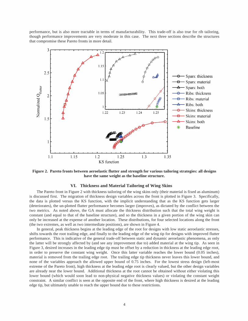
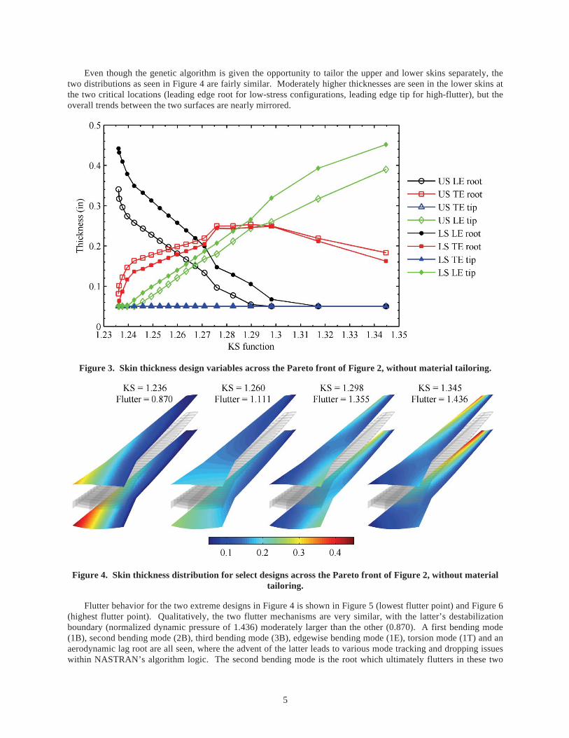
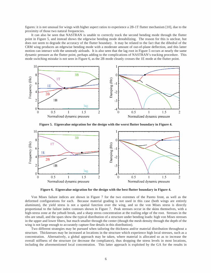
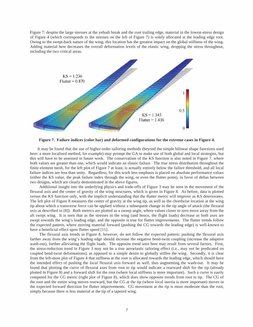
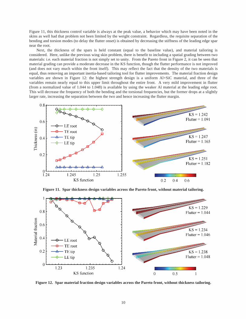
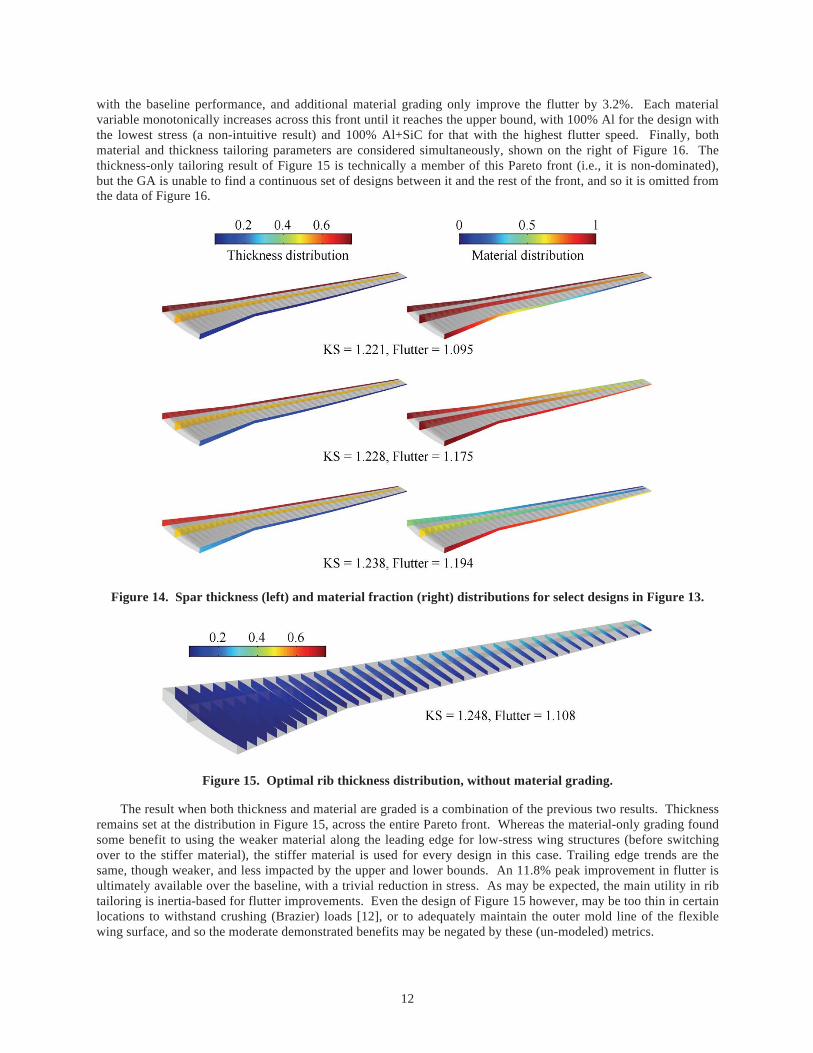
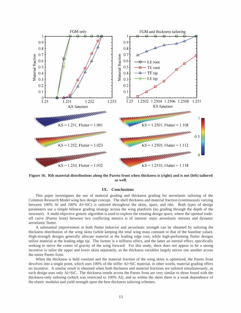