masterthesis - adaptive methods for data management in rfid
TRANSCRIPT

Masterthesis
Adaptive Methods for Data Management in RFID-based Supply Networks
von
Ulrich Kraft
Matrikel 7179197 FernUniversität in Hagen Fakultät für Mathematik und Informatik Lehrgebiet Kommunikationsnetze Master-Studiengang Elektro- und Informationstechnik 10.08.2007 Betreuer: Prof. Dr.-Ing. habil. Herwig Unger Lehrgebiet Kommunikationsnetze Prof. Dr. Jörg Keller Lehrgebiet Parallelität und VLSI


Contents
Contents
Figures........................................................................................................ III
Tables ..........................................................................................................IV
Formulas .....................................................................................................IV
Abstract......................................................................................................... 5
Zusammenfassung........................................................................................ 5
1 Introduction ...................................................................................... 7 1.1 Supply networks ................................................................................. 7
1.2 Motivation .......................................................................................... 8
2 Business scenarios........................................................................... 11 2.1 Counterfeit products and illicit trade ................................................ 11
2.1.1 Transportation safety................................................................. 11
2.1.2 Patient safety ............................................................................. 11
2.1.3 Brand reputation and image ...................................................... 12
2.2 Product tracking................................................................................ 13
3 Supply network infrastructures .................................................... 15 3.1 RFID as key technology ................................................................... 15
3.2 EPCglobal Network.......................................................................... 17
3.3 Global Data Synchronization Network............................................. 19
3.4 ICE peer-to-peer information system ............................................... 20
3.5 Research initiatives........................................................................... 22
3.5.1 SToP.......................................................................................... 22
3.5.2 BRIDGE.................................................................................... 22
3.5.3 IT FoodTrace............................................................................. 23
3.6 Drawbacks ........................................................................................ 24
4 Supply network simulation setup.................................................. 26 4.1 Simulation platform (Layer 1).......................................................... 26
4.1.1 Routing algorithm ..................................................................... 26
4.2 Encapsulating the platform's routing method ................................... 27
4.3 Supply network model...................................................................... 28
4.4 Party implementation (Layer 2)........................................................ 30
4.5 Product movement (Layer 3)............................................................ 33
I

Contents
4.6 Pedigree movement (Layer 4) .......................................................... 33
4.6.1 Electronic data exchange .......................................................... 34
4.6.2 Forward movement ................................................................... 34
4.6.3 Backward movement................................................................. 35
4.7 Dedicated query station (X Manager) .............................................. 35
4.7.1 Wildcard searches ..................................................................... 36
4.7.2 Querying pedigrees ................................................................... 36
4.7.3 Querying remote information.................................................... 39
4.8 Definition of supply network structure............................................. 40
4.9 Definition of dynamic behaviour...................................................... 41
4.10 Deployment of network configuration graph ................................... 42
5 Definition of protocols and data units .......................................... 43 5.1 Message format................................................................................. 43
5.2 Message types................................................................................... 44
5.2.1 Data elements............................................................................ 45
5.3 Party Interaction Protocol................................................................. 46
5.3.1 ProductDelivery ........................................................................ 47
5.3.2 PedigreeDelivery....................................................................... 47
5.3.3 PedigreePropagation ................................................................. 48
5.4 Data Query Protocol ......................................................................... 49
5.4.1 Querying pedigrees ................................................................... 49
5.4.2 Querying remote information.................................................... 50
6 Pedigree construction..................................................................... 52 6.1 Technique ......................................................................................... 52
6.1.1 Construction steps ..................................................................... 53
6.2 Communication effort....................................................................... 56
6.2.1 Upstream ................................................................................... 56
6.2.2 Downstream .............................................................................. 58
7 Pedigrees in practice....................................................................... 61 7.1 Case studies ...................................................................................... 61
7.2 Defective part identification and vehicle recall ................................ 61
7.2.1 Note on centralized approaches ................................................ 66
7.3 Tracking a product in the supply network ........................................ 66
8 Conclusion and future work .......................................................... 69
II

Contents
A Appendix ......................................................................................... 70 A.1 Supply network structure.................................................................. 71
A.2 Resource CD..................................................................................... 74
Bibliography ............................................................................................... 75
Statutory Declaration ................................................................................ 79
Figures Figure 1: Simplified supply chain.................................................................. 7
Figure 2: Closing the media-gap.................................................................. 16
Figure 3: EPC format (General identifier 96-bit) ........................................ 17
Figure 4: Querying EPC item data............................................................... 18
Figure 5: Key components in GDSN........................................................... 19
Figure 6: Building the 2D routing mesh ...................................................... 27
Figure 7: Determining routing direction ...................................................... 27
Figure 8: UTHPeer and ContentHandler interface ...................................... 28
Figure 9: Layers in supply network model .................................................. 29
Figure 10: Interaction between party and simulation platform.................... 30
Figure 11: GUI for examining party input and output queues..................... 31
Figure 12: Simple process-deliver cycle...................................................... 32
Figure 13: Simulating product delivery ....................................................... 33
Figure 14: Pedigree movement .................................................................... 34
Figure 15: X Manager - Queries, Results and PDUs ................................... 35
Figure 16: X Manager GUI for querying pedigrees..................................... 37
Figure 17: Pedigree visualization as tree ..................................................... 38
Figure 18: X Manager GUI for querying information ................................. 39
Figure 19: Information response.................................................................. 40
Figure 20: Sample supply network configuration graph.............................. 40
Figure 21: Behavioural properties ............................................................... 41
Figure 22: SuppNetMessage class diagram ................................................. 45
Figure 23: Supply network's EPC format .................................................... 45
Figure 24: Product delivery ......................................................................... 47
Figure 25: Pedigree delivery........................................................................ 47
Figure 26: Pedigree propagation.................................................................. 48
Figure 27: Querying pedigrees..................................................................... 49
III

Contents
Figure 28: Querying remote information..................................................... 50
Figure 29: Types of nodes............................................................................ 52
Figure 30: Pedigree/propagation data for different spreading factors ......... 58
Figure 31: Generated data during downstream handling............................. 59
Figure 32: Model (1-1-4) Minimizing structure .......................................... 63
Figure 33: Model (2-2-4) Medium structure................................................ 64
Figure 34: Model (2-4-4) Maximizing structure.......................................... 64
Figure 35: Messages for identifying supplier .............................................. 65
Figure 36: Number of withdrawal notifications........................................... 65
Figure 37: Conventional status website-based tracking............................... 67
Figure 38: Integrated tracking over company borders................................. 68
Tables Table 1: Overview of message types ........................................................... 44
Table 2: Pedigree construction example ...................................................... 54
Table 3: Propagation in detail ...................................................................... 55
Table 4: Overview of SF, depth and parties in upstream............................. 57
Formulas Formula 1: Determining total parties in upstream ....................................... 57
Formula 2: Determining total pedigree data in upstream handling ............. 57
Formula 3: Determining total propagation data in upstream handling ........ 57
Formula 4: Determining total pedigree data in downstream handling ........ 59
Formula 5: Determining total propagation data in downstream handling ... 59
IV

Abstract
Abstract Modern infrastructures for supporting supply network interaction realize
purely centralized approaches with global services registering data related to
product flows along the supply network. It is in those service's nature to
become performance bottlenecks or fail in some situations.
This thesis gives an overview of centralized infrastructures and identifies
their main drawbacks. It presents the concept of product pedigrees,
representing a product's history and future and how product related data can
be moved from central to local storage at party level.
The approach consists of pedigree construction techniques, a production
feedback concept and all related protocols and data units. It is implemented
as proof of concept on top of an existing P2P simulation platform where
correctness and communication effort are examined.
The concept's effectiveness is proven by investigating its use in the business
scenarios product identification/recall and product tracking.
Zusammenfassung Moderne Liefernetzwerke basieren auf Infrastrukturen, die zur Speicherung
von produktflussbezogenen Daten durchweg zentralisierte Dienste anbieten.
Diese Dienste können oftmals Engpässe darstellen oder in manchen
Situationen ganz ausfallen.
Die vorliegende Abschlussarbeit gibt einen Überblick über solche
Infrastrukturen und identifiziert deren Hauptschwächen. Sie stellt das
Konzept des Produktlebenslaufes, der die Vergangenheit und Zukunft eines
Produktes enthält, vor. Weiterhin zeigt sie auf, wie durch das Konzept
produktbezogene Daten in teilnehmerlokalen Datenspeichern abgelegt
werden können.
Der Ansatz umfasst Mechanismen zur Erstellung solcher Lebensläufe, ein
Rückmeldungskonzept sowie alle zugehörigen Protokolle und Meldungen
um auf beim Teilnehmer vorgehaltene Daten zuzugreifen.
5

Zusammenfassung
Um die Machbarkeit aufzuzeigen wird der Ansatz auf Basis einer
existierenden P2P Simulationsplattform implementiert. Daran werden
Korrektheit und Kommunikationsaufwand untersucht.
Abschließend werden die Vorteile des Ansatzes an den Anwendungsfällen
Produktidentifikation/-verfolgung und Produktrückruf nachgewiesen.
6

Introduction
1 Introduction
1.1 Supply networks
Almost every item which we get in touch with in our daily life has
undergone certain construction, distribution and delivery processes before it
has become part of our environment. Those various business instances which
have taken part in the item's handling form the so-called "supply chain"
which is "…the aggregation of value-adding processes…" (translated from [FRA06])
and represents product flows from raw material suppliers to final distributors
and shops (see Figure 1).
ERPsystem
raw materialsuppliers
componentsuppliers
manufacturer wholesaler
distributor
shop
consumer
scope of supply chain management
Figure 1: Simplified supply chain
The first half of the supply chain, from raw material suppliers to the
manufacturer, is called "upstream" path, whereas the second half, from
manufacturer to the final customer, is denoted as "downstream" path (see
[GS107b] bottom figure).
For supply chains do not exist separated from each other, the term "supply
network" is commonly used to describe a whole group of supply chains -
often in a domain specific field like consumer goods, aviation, automobile,
pharma and so on.
One of the traditional disciplines in the supply network context is to
orchestrate the business parties behaviour in order to increase the overall
7

Introduction
benefit and to lower the risk of negative interaction results like the so-called
"Bullwhip" effect [GIL07], where small changes in customer demand lead to
extreme changes in order behaviour at the beginning of the supply chain.
This discipline of coordinating business interaction is referred to as "Supply
Chain Management" (SCM) and covers "…planning, steering and controlling of
processes and the respective information…" (translated from [LOG07]). It is done
on an inter-company level.
Information exchange within the supply network is also very important when
it comes to the efficient implementation of use cases like tracking products,
recalling items from within the network and the containment of illicit trade
and product piracy.
All these disciplines rely on an intense exchange of automatically registered
real-time information on products.
One of the enabling technologies for barrier-free automatic data capturing
(see [FLE01]) these days is "Radio Frequency Identification" (RFID). By
tagging items with RFID labels, they get a unique identity which gets
readable by machines in a fast and efficient manner.
Researchers speak about the "Internet of things" [MAT05], where every item
is equipped with its unique RFID identity and is represented by a kind of
homepage in company spanning information networks.
1.2 Motivation
Modern systems for data management in RFID-based supply networks suffer
from their centralized approaches. Data or references of data are usually
stored in global database services. These concepts still lack efficient
mechanisms for discovering product related information, which is usually
spread over company borders and different ERP systems. Simple following-
the-chain approaches are in place, but those are far from offering adequate
performance or failure-resistance.
This thesis aims at developing a technical infrastructure concept for
supporting supply network interaction, which follows a distributed approach
instead of relying on global services. It implements party interaction
8

Introduction
protocols for a step-by-step construction of a product's pedigree as the
product moves through the network. This pedigree information is also
handed on to parties, which have handled a particular product at an earlier
stage. Thus enabling fast product recall and product tracking capabilities. For
that purpose a data query protocol will be developed, which allows querying
of remotely held data from parties along the product's path. The new
approach no longer relies on central services to look up a product's pedigree
or data but can utilize a key-based overlay routing service from the
simulation platform for fast pedigree and data discovery. The following
concepts form the basis of the new approach:
• Introduction of a peer-to-peer-based interaction model without the need to
have centralized infrastructure services in place.
• Aggregation of all parties that handled a particular EPC and all parties that
contributed parts, components, ingredients, transport services etc. to that
EPC, in a graph-like structure (pedigree). With vertices representing
parties and edges representing business-relations and product movement.
Each pedigree is further completed while the product moves through the
network and is handed on to the next party in the chain, using a party
interaction protocol.
• Backward propagation of production events enables parties to keep track
of their products.
• Parties offer interfaces for querying product information through a data
query protocol.
• A party can choose not to hold data locally but to put inline data to the
pedigree structure.
Chapter 2 will come next and present some real-life business scenarios like
product piracy, illicit trade, product tracking and product recall. The latter
two will be used in Chapter 7 to prove the decentralized data management
approaches efficiency. Additional legal business drivers will be presented as
well.
Chapter 3 will start with a short technical overview of RFID as a key
technology in the supply network context and present the status quo by
9

Introduction
looking at three selected business infrastructures used today. It will further
give an overview of three important research initiatives and close with
outlining the infrastructures' and initiatives' drawbacks.
Chapter 4 will introduce the utilized simulation platform which will be used
for simulating supply network interaction and present the logic which is
implemented in our supply network party to enable this interaction. It will
also show how the product and data flow can be examined by using a query
station. It closes with the definition of the supply network's structural
definition and its behavioural properties.
Chapter 5 will present the protocols which have been developed for enabling
the distributed data management and present the protocol data units' XML
definitions.
Chapter 6 will describe the technique of pedigree construction in the forward
and backward direction in detail so that it becomes clear how that important
structure evolves. It will also investigate the amount of data that needs to be
handled when such pedigrees are constructed and present the communication
effort in relation to the supply network's structure.
Chapter 7 will have a look at the advantages of the data management concept
in real-life scenarios like product recall and product tracking, compared to
centralized and following-the-chain approaches.
Chapter 8 will give a conclusion and some notes on future work dealing with
product authentication.
The appendix contains the supply network structure XML definition as well
as all source-code and software resources necessary for running the supply
network on CD.
10
Business scenarios
2 Business scenarios
2.1 Counterfeit products and illicit trade
Fighting against product piracy and illegal trade with law-regulated products
(e.g. pharmaceuticals) is one of the main business drivers for using RFID in
modern supply networks. Almost every industry has to deal with that
problem, ranging from machine spare parts for the automotive and aviation
industry, over consumer goods for everyday use (gasoline, beverages,
cigarettes, electronics, music, even food) and luxuries (perfumes, handbags,
clothes of luxury brands) up to pharmaceuticals. These goods are mainly
produced in the countries of Eastern Europe, especially those that emerged
from the former Soviet Union, the Middle East and the Far East, with China
being in the first place [RFA05].
Some aspects of the impact that product piracy and illicit trade have on
business today will be presented in the next chapters.
2.1.1 Transportation safety
This issue is one of the main concerns for the aviation and automotive
industry today. Spare parts in this sector are often high priced and so there
exists a great number of counterfeit parts on the market. Another aspect is
that formerly stolen parts are usually re-entering the supply network and help
illicit dealers to make profit out of them. It is important to note, that the
impact of counterfeit safety critical machine parts is not limited to these
industries, which we get in touch with each day. Even spare parts for
military submarines and aircrafts, nuclear power plants and NASA's
(National Aeronautics and Space Administration) space shuttle are subject to
faking [GAO90].
2.1.2 Patient safety
The same as for aviation spare parts applies to pharmaceuticals. Here it is the
patient to suffer from counterfeit products with no therapeutic or even with
harmful effects. As the FDA (Food and Drug Administration) stated, the
number of investigations concerning counterfeit drugs has risen from 5 cases
in 1997 to 22 in 2003 [FDA04], 58 in 2004 and 32 in 2005 [PW06]. This is
11
Business scenarios
quite much for the American market, due to its intensive supervision by law-
enforcement agencies and very strict legal regulations. Figures for the
European market are different. Media regularly reports disclosures of
industry-grade production facilities, which sometimes could produce an
output of half a million tablets per day [PSM05]. Loosening the border
controls towards Eastern European countries makes distribution channels
open to flood the European market with counterfeit pharmaceuticals from
Asian laboratories. It is reported that more than half of anti-malaria drugs in
Africa are fakes [FDA04], resulting in a number of 200.000 suspected deaths
from effectless treatment each year [NYT07].
FDA has issued a report on containment strategies for counterfeit drugs in
2004 [FDA04]. They introduce the structure of an electronic document (so-
called "ePedigree") accompanying a drug from its manufacturer, through all
involved wholesalers, up to the point of sales. It was RFID to be selected as
the most promising technology. The ePedigree therefore contains
information on all parties from the pharmaceutical item's chain of custody.
Two parties in that chain establish mutual trust by signing the data that is
attached to the ePedigree through their business interaction. FDA has made
quite optimistic forecasts and stated that manufacturers and wholesalers will
have such systems in place by the end of 2007. In the meanwhile they have
gotten enough feedback from the industry, which persuaded them to loosen
their expectations in terms of timeliness.
The State of Florida's "Drug and Cosmetic Act" [SOF05] has been amended,
so that from July, 1st 2006 on, any party involved in the distribution of drugs
needs to handle such ePedigrees. That State is the first governmental
authority to insist on the measures proposed by FDA.
2.1.3 Brand reputation and image
A trend towards improving the quality of counterfeit products can be
observed but they usually cannot compete with the original goods, which
often had yearlong development and testing cycles before being released.
Those low quality products of a certain brand lead to a lowering of customer
satisfaction for the overall brand. With prices for counterfeit luxury goods,
12

Business scenarios
which are offered as such, only being a fraction of the genuine product's
price. Thus the brand experiences broader distribution and this leads to
diminishing the brand's character as a luxury good manufacturer, and hence
will lead to a drop of sales among the targeted consumer group.
2.2 Product tracking
Information on a product's state and its current location is used to coordinate
business efforts and product movement in a supply network. It therefore has
to be made available for access to every party, which is engaged in the
supply chain process. Product tracking stands for a type of application,
which discovers product information from data sources within the supply
network and presents that data to a user or a system. Most people have
already come in touch with these systems by using web portals (e.g.
[UPS07]) for querying the shipping status of their order before leaving the
manufacturer and afterwards, for tracking packages and freight being
transported by logistics providers. Interaction with tracking applications is
not limited to people. It is also common for a companies information system
to do automatic tracking of freight that has been announced by a supplier, for
example. The challenge for tracking applications is how to gather the
response data for such a tracking query. In general a certain identifier is used
for that query and within a few moments, information must be returned to
the caller.
The European parliament and its Council back in 2002 issued Regulation
178/2002 [EP02, especially paragraphs (28) and (29)] defining procedures in
matters of food safety. Experience from past incidents made it necessary to
declare the tracing of food and feed mandatory for all parties involved in the
food supply chain, so that:
• In case of contaminated feed, cattle, ingredients, or irregularities in the
production process, any food items that emerged from these ingredients or
processes can be tracked down and efficiently recalled from the supply
chain or the customer.
• In case of any conspicuousness related to food items along the supply
chain or at the customer, the party or ingredient can be tracked down.
13

Business scenarios
Tracking down the initiator of problems in the food supply chain is very time
consuming because most of the parties still rely on paper-based shipping
tickets and following-the-chain is the only procedure possible in most of the
cases.
RFID-based IT infrastructures promise to be an effective instrument for
enabling fast responses in cases of food recalls by creating an ePedigree,
which accompanies animals, feed, ingredients and food items. The same
concept can be applied to other non-food goods as well.
After having presented the real-life background of this thesis, the following
chapter will outline the reasons why RFID is regarded as the key technology
for improving supply network interaction. It will give an overview of three
current network centric infrastructures for supporting that interaction. They
represent the current information technological basis for the business
scenarios just mentioned. It will also outline the drawbacks of these
infrastructures and present important research initiatives.
14

Supply network infrastructures
3 Supply network infrastructures
3.1 RFID as key technology
Radio Frequency Identification (RFID) is among the technologies, which are
in the center of attention of consumers as well as the industrial and academic
community today (see [GIL07] Figure 2-2: "Presence of current SCM
concepts in media (Source: Logistik Heute)"). According to the Gartner
Group's "Hype Cycle" (see [GIL07] Figure 2-3) RFID has just left the
"through of disillusionment" and is on its way to the "slope of maturity". It is
regarded as an alternative to the barcode and other similar labelling
techniques (see [FRA06] p. 71 for a classification), which are in widespread
use. RFID offers contactless sensing of information when tagged products
get into the range of RFID reader equipment. Compared to barcode labels,
RFID offers the following advantages (for technical specifications of
common transponders and readers, see [FRA06] pp. 48-55):
• Internal memory with a capacity of several kBytes.
• Transponder tags use radio frequency to communicate with readers. No
line-of-sight contact to the product is needed and tags do not have to be
attached to the outside of a product's package.
• Not only serial identification but also sensing of more than one tag at a
time becomes possible: so-called "bulk capturing" (see [WEH07] p. 2).
• Special readers can write to the tag and in that way add information to the
tag's memory or alter data that has been stored before. Using tags to store
and transport information is called "data-on-tag" technology. Storing data
on external storage systems is referred to as the "data-on-network"
paradigm [DIE07].
• Provisioning of active tags (active means they can initiate reads and writes
themselves) enables the creation of so-called "smart objects" [MAT03].
They have the ability to sense environmental data by using special sensor
devices and initiate communication with other tags or readers through
transceiver modules. A broad deployment of these tags depends on
progress made in miniaturization of processors, communication and sensor
modules and especially power supplies. Although the price for these tags
15
Supply network infrastructures
is quite high, there do exist some use cases, which justify their
deployment. An extensive presentation of active sensor node's
architectures and protocols can be found in [WSN05].
This thesis will be based on the utilization of purely passive tags, which only
contain a small amount of immutable data - usually a single globally unique
ID for the tagged product.
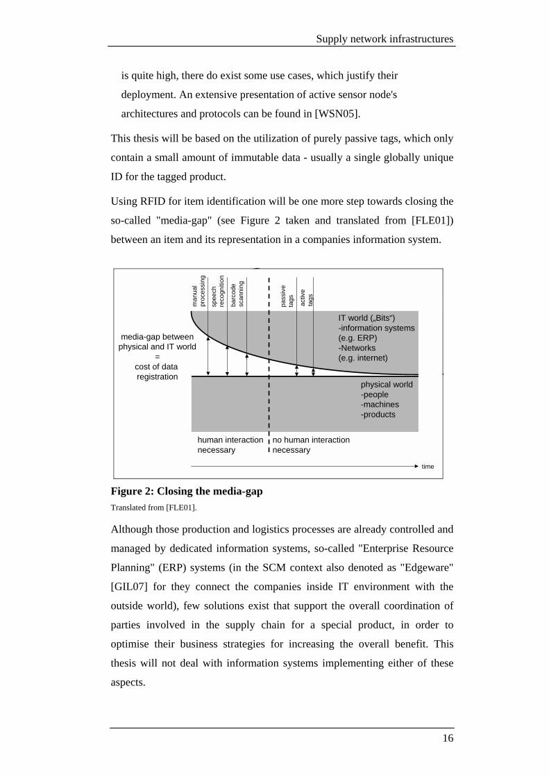
Using RFID for item identification will be one more step towards closing the
so-called "media-gap" (see Figure 2 taken and translated from [FLE01])
between an item and its representation in a companies information system.
human interaction necessary
no human interaction necessary
media-gap betweenphysical and IT world
=cost of data registration
man
ual
proc
essi
ng
spee
ch
reco
gniti
on
barc
ode
scan
ning
pass
ive
tags
activ
eta
gs
physical world-people-machines-products
IT world („Bits“)-information systems (e.g. ERP)-Networks (e.g. internet)
time
Figure 2: Closing the media-gap Translated from [FLE01].
Although those production and logistics processes are already controlled and
managed by dedicated information systems, so-called "Enterprise Resource
Planning" (ERP) systems (in the SCM context also denoted as "Edgeware"
[GIL07] for they connect the companies inside IT environment with the
outside world), few solutions exist that support the overall coordination of
parties involved in the supply chain for a special product, in order to
optimise their business strategies for increasing the overall benefit. This
thesis will not deal with information systems implementing either of these
aspects.
16

Supply network infrastructures
It will instead deal with the technical infrastructure and protocols that need
to be installed in order to provide the data management basis for any higher-
level system, which is offering supply chain management functionality.
3.2 EPCglobal Network
EPCglobal Inc. [EPC07b] is aimed at developing a global infrastructure that
supports information management for products moving through a supply
network. While the conceptual work for the network has been done by the
Auto-ID Center at the Massachusetts Institute of Technology (MIT)
[MIT07], EPCglobal Inc. is part of Global Standards 1 (GS1) [GS107] - an
organization bringing together stakeholders from industry in order to
develop standards in the field of RFID technology and supply chains. It is
mainly targeted at the consumer goods industry and its goal is to provide a
system, that can be used by industries like aviation, automotive, pharma, and
so on as well. EPCglobal's main concern is to develop standardized
interfaces and formats for interaction with their network in order to achieve
interoperability between different ERP systems and the global infrastructure.
Each item is identified by the so-called "Electronic Product Code" (EPC)
[EPC04] (see Figure 3).
Header GeneralManagerNumber
Object Class Serial number
GID-96 8 28 24 36
00110101
(BinaryValue)
268,435,456
(DecimalCapacity)
16,777,216
(DecimalCapacity)
68,719,476,736
(DecimalCapacity)
Figure 3: EPC format (General identifier 96-bit) From [EPC04], p. 19.
It has a hierarchical structure with the following essential elements:
• Version (in the Header)
The EPC's version.
17

Supply network infrastructures
• General manager number
This identifier denotes the company that was issued this EPC, representing
the location of item information.
• Object class
States the class, to which this item belongs.
• Serial number
This is a unique identifier in the numbering-space for that particular item
class at the EPC manager.
These three elements make up a globally unique identifier for each item
within the supply chain. EPC numbers are issued and managed centrally by
EPCglobal only.
ONS
localONS
EPCISERP database
EPCglobal Subscriber
Lookup of local ONS
Query for EPCIS Interface
Query for item information
EPC
returns: URL(local ONS)
returns: URL(EPCIS)
EPC
EPC
returns: Information
Figure 4: Querying EPC item data
The global Object Naming Service (ONS) [ONS03] is the infrastructure's
central element. It is a directory service that maps EPCs (especially the
manager part of the EPC) to the Internet URL of the local ONS operated by
the company, which holds data for the EPC. After having received the URL,
a subscriber can use it to query that local ONS for the interface of the
EPCIS, that holds data for the item of interest (see Figure 4).
The so-called "EPC Information System" (EPCIS) [EPC07] is the
middleware system, which runs in the local IT environment of each
subscriber. It connects the company-specific ERP systems with the global
infrastructure, offering an interface for other subscribers, through which they
can query information.
18

Supply network infrastructures
EPCglobal also covers standardization on lower levels, like tag, air and
reader interfaces. This is out of the scope of this thesis.
3.3 Global Data Synchronization Network
The Global Data Synchronization Network (GDSN) [GDS06] initiative was
created as a common effort by the European Article Number (EAN) and the
Uniform Code Council (UCC) organizations. Their distinct numbering
systems have been combined to form a standard item-level identification
number in the European, American and Asian market - the Global Trade
Item Number (GTIN) [GTI04]. It is again GS1 to operate the central
infrastructure components of the GDSN.
GDSN can be regarded as a form of messaging middleware on a supply
chain level, which follows the publish/subscribe messaging paradigm.
GlobalRegistry
ERP database
GDSN party
DataPool
DataPool
DataPool
ERP database
GDSN party
ERP database
GDSN partysynchronization
Data PoolProviders
Operated byGDSN
publish/su
bscribe
publ
ish/s
ubsc
ribe
publish/subscribe
Figure 5: Key components in GDSN
The following list presents the key components (see their relationships in
Figure 5), which make up the GDSN:
• GDSN business partners
Those are mostly suppliers and retailers, which are publishers and
subscribers to the system. They are identified by their Global Location
Number (GLN).
19

Supply network infrastructures
• Data pools
This is the physical storage of an item's information, which can be created
and changed by publishing information and read by using the notion of
subscriptions. Subscribers have the choice to operate data pools on their
own but in most cases this service is offered by data pool providers,
certified by GS1.
• Global registry
The central element is operated by GS1. It acts as an information broker
by managing subscriptions and distributing information events to the
target data pools.
Whenever items are registered with GDSN, the data triple of GTIN, GLN
and Target Market (TM) are its system relevant properties. Any other party
that wants to subscribe to certain events, can use any combination of these
identifiers to state its profile of interest.
GDSN's aim is to support information exchange by means of information
brokering in order to assure data synchronization between parties in the
supply network. By supporting unspecific queries, like simple target market
criteria, the role of the system as a marketplace for suppliers and retailers
becomes obvious.
3.4 ICE peer-to-peer information system
Supply network participant's business efforts (ordering, status, production,
delivery and storage) have to be harmonized in order to increase their overall
benefit [LOG07]. Sharing and accessing information is the key to that kind
of supply chain management. There exist various kinds of ERP systems and
other applications, that offer data for other parties to query and that need to
get information from other information systems. Many technologies for
standardizing those information requests and interfaces to access information
services are in use. SOAP (Simple Object Access Protocol) [W3C03] has
become a widely adopted interface standard for that purpose. It heavily relies
on XML formatted documents used to exchange data, hiding details
concerning a service's programming language or platform from the caller.
Integration of systems is done by Enterprise Application Integration (EAI)
20

Supply network infrastructures
software tools [KEL02]. While integration within one administrative domain
(e.g. one single company) can be an easy and straightforward task, more
problems come up when services across different administrative domains
have to be accessed and orchestrated for fulfilling a special business process
(as it might be the case for supply chain management). The switch from
intra-domain integration with reliable communication links and systems
under the integrator's own supervision on to inter-domain integration brings
up different kinds of problems (taken from [ICE06]):
• Separation of information services from a public network by firewalls
• Dynamic IP addresses for service access
• Communication over unreliable network links
• Integration of systems with unknown uptime and downtime cycles
For these reasons it is hard to do inter-domain integration with software that
relies on the classical client/server concept and so another abstraction layer
(a so-called "middleware") has to be introduced.
The ICE system [ICE06] is such a concept. It integrates SOAP-enabled
services from various domains with full transparency of a service's address,
location and distribution. Functionality in ICE is implemented in three levels
(taken from [ICE06]):
• Application level
ICE here uses a component which does the actual orchestration of the
services that are engaged in fulfilling a business process. It is an engine,
which implements the use case specific workflow steps and manages their
execution.
• Services level
Services are presented by their interfaces. They have to be made
accessible for other parties.
• Middleware level
The abstraction which offers the various aspects of transparency is
implemented at the middleware level. ICE uses the JXTA [JXT07] peer-
to-peer overlay network - an industry-grade and mature communication
middleware. EAI client tools are able to access a service's interface
21

Supply network infrastructures
through the middleware by using service addresses from a unified naming
space that hides the actual underlying network structure, the service's
location and the specific instance of the service (when more than one
instance of the same service is in place).
3.5 Research initiatives
There exist various research initiatives especially on an European level.
What they have in common is that they try to address the modern use cases
like product piracy and food tracking by introducing new or leveraging
existing supply chain management business infrastructures.
3.5.1 SToP
The SToP (Stop Tampering of Products) project was started in November
2006 as an initiative founded by the European Commission. It is primarily
aimed at "developing means to stop illicit trade and counterfeiting products entering
supply networks by establishing ambient-intelligence among trading partners through
providing a network-oriented information system" [STO06]. The following
requirements should be met (all extracted from [STO06]):
• Non-cloneable tags
• Capability to track items along the chain
• User-friendliness
• Cost-effectiveness
• Integration of manufacturers, vendors, customers and other authorities
(e.g. customs)
Industrial project partners for SToP include SAP, Novartis and Airbus. So it
is mainly targeted at the pharma and aviation sectors.
The work package that will cover the design and implementation of a
working prototype for a product authentication network is scheduled for May
2008.
3.5.2 BRIDGE
The BRIDGE (Building Radio Frequency IDentification for the Global
Environment) project was set up by the European Commission in 2006 and
22

Supply network infrastructures
has a broader objective than the SToP project. Anti-counterfeiting strategies
are just some of its objectives. It brings together various partners from
different industries for research, development and implementation of the
EPCglobal network technology in Europe. Among the defined work
packages are (all extracted from [BRI06]):
• Hardware development
• Serial look-up service
• Serial-level supply chain control
• Security
• Anti-counterfeiting
• Implementing the drug pedigree
• SCM
• Manufacturing process application
• Management of reusable assets
• Management of products in service
The who-is-who of BRIDGE includes five GS1 organizations (plus the
global coordinator and GS1 China), the universities of Cambridge (United
Kingdom), Zurich (Switzerland), Fudan (China) with their respective Auto-
ID Labs and the universities of Barcelona (Spain) and Graz (Austria).
Among the industrial partners are Kaufhof, Gardeur, Nestle and Sony. With
BT, SAP and Verisign acting as solution providers and implementers.
3.5.3 IT FoodTrace
This project consists of a partnership of 30 institutions, under the lead of the
Life Science Center of the University of Hohenheim (Germany) and IBM
Deutschland GmbH. It is supported by the German Federal Ministry for
Education and Research. Its goal is to develop a portal-based information
system which the initiative claims to be the "first sustainable integrated IT system
without structural breaks and barriers" [IFT06] and should - in the first version -
offer barrier-free data management of meat products throughout the whole
value-chain. In later stages, it shall cover tracing of all food which is of
animal origin.
23

Supply network infrastructures
3.6 Drawbacks
The centralized approaches EPCglobal network and GDSN with global
directory services like the ONS represent a single-point-of-failure or at least
a performance bottleneck as it is the case for most centralized services even
in other business domains, which are mostly made failure-resistant by
replicating the service's hard- and software. This implies additional cost and
higher maintenance effort.
Especially when it comes to access those services through public networks
like the Internet, they are likely to become subject to Denial-of-Service
(DoS) attacks. As the Computer Security Institute stated in [CSI05] DoS
attacks make up one third of all types of attacks in the Internet and can be
accounted for a loss of more than 7 million US$ in 2005.
Failure would result in slowing down product flows in the supply chain or a
halt of all business activities in the worst case.
The infrastructure furthermore does not implement any discovery services
yet, which would be useful, when trying to locate remote ONS/EPCIS
instances that hold information on a particular EPC item, but do not belong
to the EPC manager. The only way to handle this at the moment in the
EPCglobal network is to look for any references to other ONS instances in
the manager's EPCIS and then jumping from hop to hop and querying each
EPCIS on the way. This strategy is called "following-the-chain". It is neither
efficient, nor tolerant to failures of EPCIS instances along the chain. The
ICE system in contrast offers discovery services through the notion of
content-based routing methods. It could serve as a middleware basis for any
higher-level SCM supporting application because it additionally offers
failure-tolerance through service location transparency.
It is open to what extend the research initiatives just mentioned will reach
their goals. However, none of them seems to be directed towards an
architectural change from centralized services towards peer-based
approaches. This is especially true for BRIDGE, as it focuses on the
EPCglobal network infrastructure.
24

Supply network infrastructures
Now that the main drawbacks of modern supply network infrastructures have
been outlined, the next chapter will give a short introduction to P2PNetSim,
which is the simulation environment that is used within this thesis.
It will also present the components which were developed on top of the
simulation platform in order to create realistic supply network interaction. It
will show the structural definition of the network and give an introduction to
the resulting product and pedigree flows among parties and present a query
station implementation for investigating the decentralized data management.
25

Supply network simulation setup
4 Supply network simulation setup
4.1 Simulation platform (Layer 1)
Parties (companies) need to exchange data and products to fulfill their
product processing duties. A simulation platform that offers a message-based
transport mechanism for reliably delivering text messages between parties is
used (see "Layer 1" in Figure 9). It also triggers the production process of a
party by granting it processing time. The platform furthermore collects status
information from parties. This makes auditing information accessible in one
single place for analyzing the simulation.
A detailed description of the P2PNetSim simulation platform can be found in
[COL06]. The platform represents a highly scalable execution environment
for parallel peer-to-peer networks and is implemented in the Java language.
So-called "simulation agents" are responsible for a group of simulated
parties and conduct their lifetime management (configuration and
execution). The simulation agents themselves are controlled by a single
instance of the so-called "simulation control agent", which sets up the
simulation agent architecture. This includes configuration and status dumps
during execution. The various instances of simulation agents and the
associated simulation control agent use the Java Agent Development
Framework (JADE) [JAD07] platform for communication.
4.1.1 Routing algorithm
Work is in progress to equip the simulation platform with a key-based
overlay routing mechanism [UNG07]. It fits the needs of a supply network's
data flow very well because it is tailored to use the EPC identifier for
addressing parties. The algorithm therefore splits the identifier of a party into
two equal sized halves. These halves represent the parties coordinates in a 2-
dimensional routing mesh. Every peer establishes routing relationships to the
8 nearest peers in the surrounding (upper, right-upper, right, right-lower, and
so on) of the 2-dimensional space by application of a mesh building
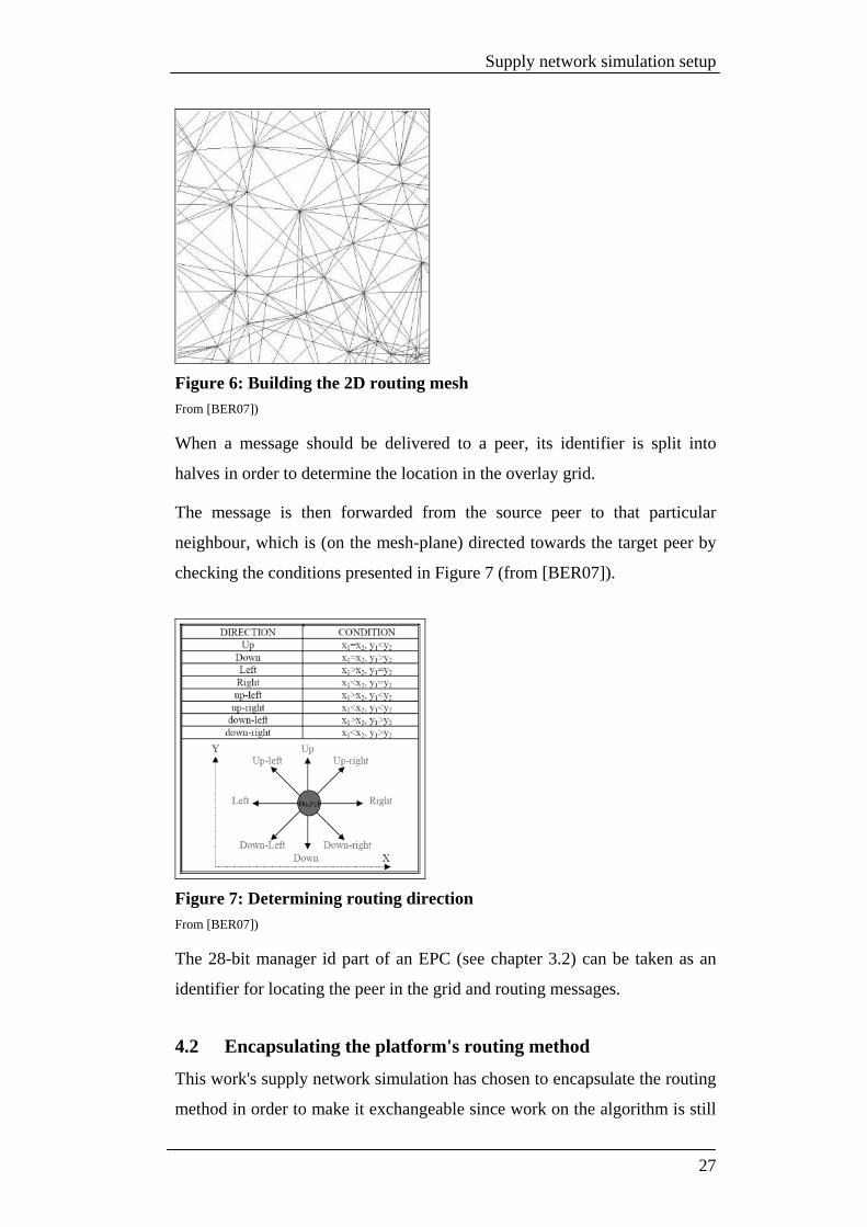
algorithm. Figure 6 (from [BER07]) shows such a mesh consisting of 32
peers.
26
Supply network simulation setup
Figure 6: Building the 2D routing mesh From [BER07])
When a message should be delivered to a peer, its identifier is split into
halves in order to determine the location in the overlay grid.
The message is then forwarded from the source peer to that particular
neighbour, which is (on the mesh-plane) directed towards the target peer by
checking the conditions presented in Figure 7 (from [BER07]).
Figure 7: Determining routing direction From [BER07])
The 28-bit manager id part of an EPC (see chapter 3.2) can be taken as an
identifier for locating the peer in the grid and routing messages.
4.2 Encapsulating the platform's routing method
This work's supply network simulation has chosen to encapsulate the routing
method in order to make it exchangeable since work on the algorithm is still
27

Supply network simulation setup
in progress. Supply network parties at the moment have an omniscient
knowledge of the other parties addresses, meaning that they hold a hard-
coded mapping from EPC manager ids to the parties IP address. It is just a
matter of exchanging the implementation of the so-called "UTHPeer" class
in the current simulation with an UTHPeer implementation that supports the
mesh building and constructs the neighbourhood mapping not from a static
configuration but from a mesh building process (see Figure 8).
<<Interface>>ContentHandler
SupplyNetworkParty
UTHPeer
Peer
1
Neighbourhoodmapping
Present: static configurationReal UTH: Mesh building
Figure 8: UTHPeer and ContentHandler interface
Supply network parties are connected to the UTHPeer via the
ContentHandler interface. This makes the way free for using the UTHPeer
with its routing capabilities with other party implementations different from
the supply network context, as well.
4.3 Supply network model
The data management concepts are investigated and evaluated using a supply
network model. It consists of parties that interact with each other by
receiving, producing and delivering goods. The model shall be a simplified
representation of common supply networks, which are much more complex
in reality. A party is a participant in the supply network and represents a
product handling company. Product handling consists of the following steps:
• Receiving, registering and storing incoming products
• Adding value to the product (e.g. transporting it, refining it or using it as
component for a newly created product)
• Fulfilling orders of other parties in the supply network by delivering the
processed product
28

Supply network simulation setup
The whole production process, from a product's arrival at a company, over
its processing, up to the delivery, is usually controlled by a companies
information processing system. In modern companies, which are about to
close the media-gap, product events are no longer processed by humans but
by RFID technology. It is used to initially register incoming products and
keep track of their state during the whole production process. Products are
equipped with RFID tags (transponders) which contain a unique serial
number for identifying that product. In all the following chapters, the EPC
will be used as a standardized identification number because it is in
widespread use today. A product that is handled and transported within the
company regularly comes into the receiving range of RFID reader
components, which supply tracking and status information about that product
to the central information processing system. This can in turn regulate the
production process and do the order management.
As the supply networking model just exists as software components within
the simulation environment, there is no RFID reader equipment in place. So
the event of a product entering a companies input processing is not triggered
by sensing RFID tags, but simply by receiving a message from the supplier.
It contains a list of EPCs of the products that would have been delivered
physically in reality.
Simulation platform(communication & routing)
Supply network parties(processing and generation of products and data)
Product movement(from supplier to customer)
Pedigree movement(backward and forward along the supply chain)
Message delivery Triggering processing
Resulting flow of products
Resulting data (pedigree) exchange
Layer 1
Layer 2
Layer 3
Layer 4
Figure 9: Layers in supply network model
29

Supply network simulation setup
Figure 9 presents the simulation's different components as layers. Layer 2 to
4 will be discussed in more detail in the following chapters.
4.4 Party implementation (Layer 2)
A party is an implementation of a company as participant in the supply
network and is one of the most important implementation components, for it
realizes the innovative data management behaviour. It is also designed to
generate the product flow by looping through a simplified "receive-process-
deliver" cycle. Figure 10 shows how the party implementation is controlled
and triggered by the underlying simulation platform.
Simulation platform(communication & routing)
Supply network parties(processing and generation of products and data)
• Deliver incoming messages
• Grant execution time
• Initialization and configuration
• Collect and display status information
• Transport outgoing messages
Figure 10: Interaction between party and simulation platform
The platform most of the time transports messages to their recipients. The
whole message exchange uses a message queuing paradigm. When starting
the simulation, it is responsible for configuring and initializing the party
implementation. It grants a certain amount of working time to the party
during each time step of the simulation execution. In that step the party
fulfills its processing and data management behaviour. The party can
regularly send status information and events to the platform for displaying
and analyzing purposes. Also a GUI has been developed to visualize which
products (EPCs) have been handled at a party. It shows its parties input and
delivery queues. Whether it shall be displayed or not can be configured on a
per party basis in the supply network configuration file. The GUI seamlessly
integrates into the simulation controller GUI (see Figure 11) which is part of
the P2PNetSim [COL06] simulation platform utilized for the simulation.
30

Supply network simulation setup
Figure 11: GUI for examining party input and output queues Integrated as frame titled "postprocessor" into P2PNetSim [COL06]
A parties "process-deliver" cycle is shown in Figure 12. Through order and
delivery relationships supply networks are constructed. The party has orders
from successors in the supply network and conducts a production process to
fulfill these orders. The party itself has to check whether it has enough inputs
to do a production cycle. The input products are again delivered from
predecessors in the supply network which hold orders from this particular
party.
31

Supply network simulation setup
for(supplier)input>=needed
Produce new piece(s)
yesno
no
yes
Start
Order left?yes
Endno
Choose order
Remove order
Order‘s bunchfinished? yes
Send bunchto target
no
Orderfulfilled?
Schedule in order
Figure 12: Simple process-deliver cycle
The processing cycle's aim is not to be as realistic as possible but to be as
realistic as necessary for generating product movement along the chain, so
that the resulting data management can be investigated. The duty cycle of a
party consists of the following three general steps:
• Handling incoming messages
• Receiving and storing product deliveries
• Receiving and storing pedigree deliveries
• Receiving and attaching propagation triples
• Receiving and responding to pedigree requests
• Receiving and responding to info requests
• Production process
• Producing new products
• Generating propagation triples
• Creating outgoing messages
• Sending product deliveries
• Sending pedigree deliveries
• Sending propagation triples
32

Supply network simulation setup
4.5 Product movement (Layer 3)
Supply networks got their name from the fact that products are supplied to
one party by its predecessor in the network. That product starts at the
beginning of the network, where raw material suppliers are in place and
stops at the end of the network, where customer buy finished products in
shops. Orders have to be placed by one party during configuration time,
stating that it wants to have a certain amount of products delivered from its
supplier. A party then uses its execution time steps to produces products and
to deliver them to the party which has placed an order until the ordered
amount has been reached.
Simulation platform(communication & routing)
Product 1 Product 2Product 3 Product n
Physical transportation (delivery)
SupplyingParty
OrderingParty
Message (Product Delivery: EPC1...EPCn)
Reality
Simulation
Figure 13: Simulating product delivery
It has already been mentioned that the physical flow of products is simulated
by delivering messages that state a list of EPCs. This signifies that those
products are being delivered (see Figure 13). This simplification does not
have any effect on the outcome of the data management strategies
evaluation.
4.6 Pedigree movement (Layer 4)
Data movement in the supply network is a direct result of product
movement. Data represents a product's pedigree or parts of it and can move
into the same direction as a product ("pedigree delivery") or in the opposite
direction. This is referred to as "pedigree propagation" (see Figure 14).
33

Supply network simulation setup
Supplyingparty
Orderingparty
Formerparty
Formerparty
Formerparty
Formerparty
Formerparty
Backward propagation (1:n) Forward delivery (1:1)
Figure 14: Pedigree movement
After a party has received pedigrees, it stores them in its local data store as
initial data or it uses it for completing the incomplete pedigree, which it
already holds on a product.
4.6.1 Electronic data exchange
The simulation environment offers a reliable transport of text message
between parties. Supply network parties use that service for transferring data
and product delivery events. This mimics real-world characteristics quite
well, where companies exchange information in electronic form, too. The
Electronic Data Interchange (EDI) standard for the exchange of business
related (e.g. orders) messages is an example for that. It is in widespread use
among business parties today because of its superiority over paper-based
exchange in terms of speed and costs.
4.6.2 Forward movement
Pedigrees that move forward in the network are given from a supplier to the
recipient of a product in order to inform the recipient about the product's
history. That means about all parties which have been in the product's chain
of custody up to that point in time. The pedigree can additionally contain
inline information that was created while a product was handled at a party.
This movement is called "pedigree delivery" because it usually accompanies
a product delivery event. In this manner the pedigree is handed on and step-
by-step forms a tree structure, with the tree's root node being the product's
current handling party and the associated EPC identifier.
34

Supply network simulation setup
4.6.3 Backward movement
Whenever a party has produced a product and delivers it to the ordering
party, the process of "pedigree propagation" takes place. This means, that
each party, which is contained in the new product's pedigree (it consists of
the ingredient's pedigrees) is informed about the fact, that a new product has
been created. Data then flows in the opposite direction of the product
movement (backwards in the chain). The receiving parties use that
propagation message to complete their locally held pedigree with the
information about the newly created product. Please see chapter 6 for a
detailed description of how pedigrees are constructed.
4.7 Dedicated query station (X Manager)
Results of this thesis' new data management strategy are product pedigrees,
which are spread all over the supply network parties which handled a
particular product. Together with remotely held data at those parties which
can be of interest to other parties as well.
The supply network features special protocols for retrieving either of that
information (see chapter 5). It is the parties to use those protocols to query
pedigrees and data. For examining the data management in the simulated
supply network, a dedicated component for that purpose is introduced (see
Figure 15).
X Manager
Lookup pedigree by EPC Lookup remotely held infoby (EPC + Party-ID)
Pedigree Information (key/value pairs)
PDU: P
edigr
ee
Reque
st/Re
spon
se PDU: Info
Request/Response
Queries
Results
PDUs
Supply Network(Interacting Parties)
Figure 15: X Manager - Queries, Results and PDUs
35

Supply network simulation setup
The so-called "X Manager" is a dedicated querying station. It takes user
input, creates PDUs for sending to the supply network and subsequently
presents the network's responses to the user. Its GUI seamlessly integrates
into the simulation controller GUI that is instantiated by the P2PNetSim
[COL06] simulation platform. Just like any other supply network party
implementation, the X Manager takes part in the supply network by
implementing the common ContentHandler interface, which enables him to
send and receive messages through the simulation platform's message
queuing service. Note that the X Manager does not implement any
production process neither does it take part in a supply/order relationship. It
is just a management station that is assigned an EPC manager id because the
UTH mesh routing algorithm uses that identifier for addressing and routing
tasks.
4.7.1 Wildcard searches
Pedigrees and information can be queried with distinct EPCs or with
wildcard EPCs. The latter take the wildcard character "?" (for a single digit)
and "*" (for more digits) as valid input for the class and/or serial identifier
parts of the EPC.
4.7.2 Querying pedigrees
By entering the EPC of the product of interest into the X Manager's pedigree
querying GUI (see Figure 16), it issues a request to the party identified by
the EPC's manager identifier part. The status textarea shows whether a
pedigree (or more pedigrees, when a wildcard was used) or an errorcode has
been returned or the request has timed out and no response has been
received.
36

Supply network simulation setup
Figure 16: X Manager GUI for querying pedigrees Integrated as frame titled "postprocessor" into P2PNetSim [COL06]
Pedigrees returned from the X Manager (see Figure 17) are presented in the
form of a tree, with the current node being the root. Directed edges to
aggregate nodes are labelled with "part of" and edges to component nodes
are labelled with "made of". Every vertex is marked with the tuple {D0,D1}
(see chapter 6.1 for details), signifying where the handling has taken place
(party manager id) and what EPC the product, which resulted from that
handling, was given.
37

Supply network simulation setup
Figure 17: Pedigree visualization as tree
Figure 17 represents the pedigree of the product with the EPC 1-11-31-102
(dark grey) as stored and known to party 11. It shows that the product 1-11-
31-102 has been assembled at party 11 from the components (light grey in
the lower half) 1-10-24-63 (delivered to party 11 from party 10), 1-9-5-101
(delivered from party 9) and 1-7-26-6 (delivered from party 7). All those
components have been constructed from other components as well. This is
denoted by them having again "part of" relationships to other nodes in the
pedigree.
The pedigree's top half light grey nodes represent the handling of product 1-
11-31-102 after it has left party 11 (those are the "aggregate" nodes). The
product has travelled through party 12 where it has kept its EPC because no
form of assembly or transformation has taken place and the product has not
changed. After party 12, the product has gone unchanged through party 15
(top node) and has been delivered to party 21 (this is an instance of
customer) at the specified time.
By returning this pedigree to a querying party, party 11 can tell which
components have been used during production of the product 1-11-31-102
38

Supply network simulation setup
and which other products have emerged from it. This will be important in
product recalling situations and explained in a later chapter.
4.7.3 Querying remote information
The X Manager additionally offers an interface (see Figure 18) for querying
parties for information which they are holding on a certain product (EPC).
This X Manager component uses an EPC (or a wildcard EPC) as input and
an additional manager id identifier, stating which party shall be queried for
information on that product. This can be used for example to query
information from a set of parties which transported one single product in
order to check whether parameters like temperature etc. have stayed within a
certain range. It is again the status textarea to show the queries status
(success, errorcode or timeout).
Figure 18: X Manager GUI for querying information Integrated as frame titled "postprocessor" into P2PNetSim [COL06]
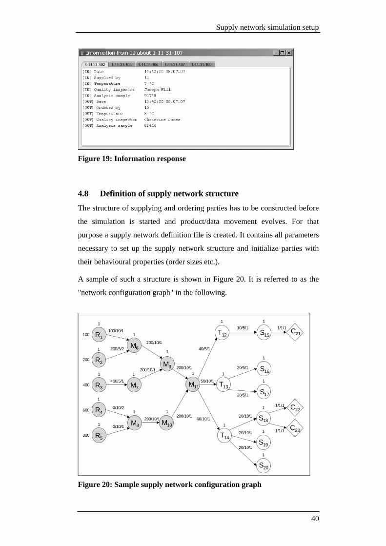
The following screenshot (see Figure 19) shows information results after
they have been queried through the X Manager on party 12 with the wildcard
EPC "1-11-31-10?".
39
Supply network simulation setup
Figure 19: Information response
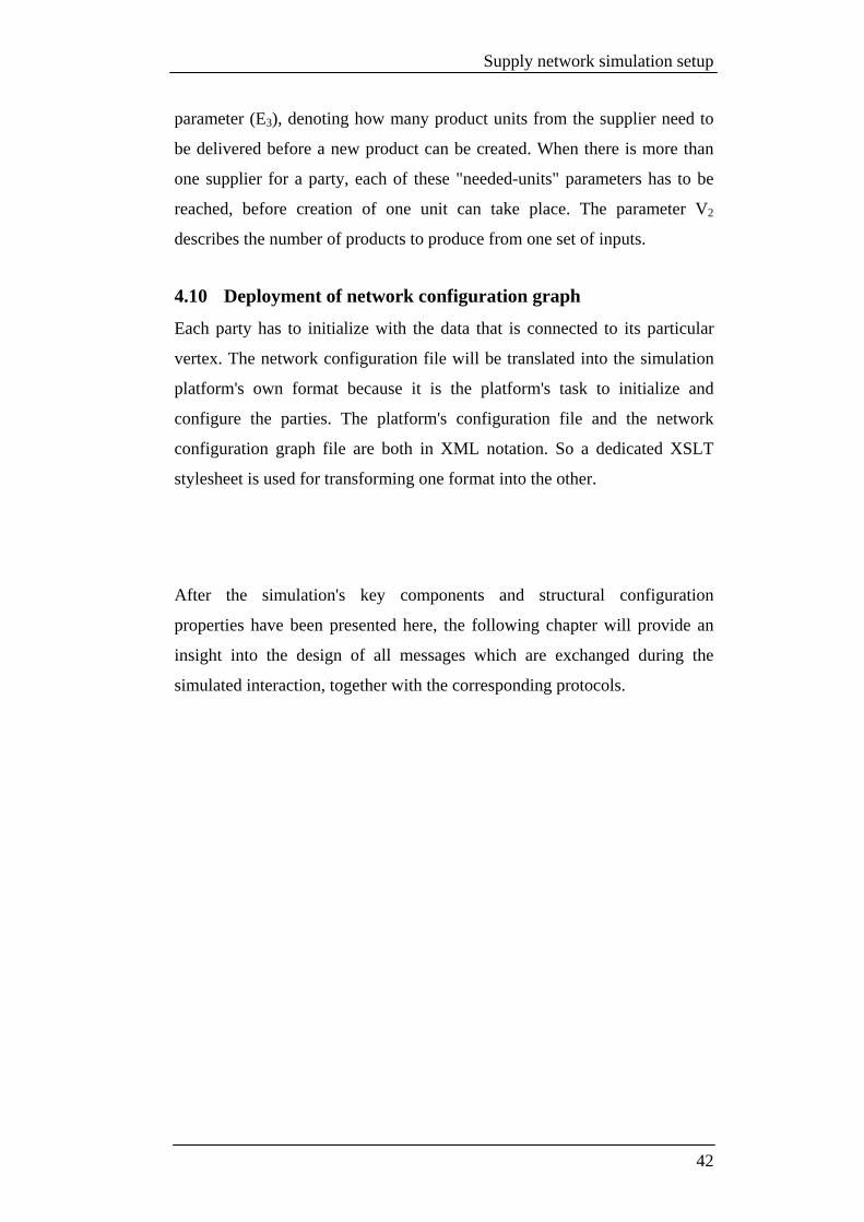
4.8 Definition of supply network structure
The structure of supplying and ordering parties has to be constructed before
the simulation is started and product/data movement evolves. For that
purpose a supply network definition file is created. It contains all parameters
necessary to set up the supply network structure and initialize parties with
their behavioural properties (order sizes etc.).
A sample of such a structure is shown in Figure 20. It is referred to as the
"network configuration graph" in the following.
R1
R2
M7
M6
M9
T12
S17
S19
C21
R3
100
200
400
100/10/1
200/10/1
1
1
1
1
1
1
1
1
1
R4
R5
600
300
1
1 M8
1
M10
1
M11
2
T13
1
T14
1S18
1
S20
1
S16
1
S15
1
C22
C23
200/5/2
400/5/1
0/10/2
0/10/1
200/10/1
200/10/1
200/10/1
200/10/1
50/10/1
60/10/1
40/5/1
10/5/1
20/5/1
20/5/1
20/10/1
20/10/1
20/10/1
1/1/1
1/1/1
1/1/1
Figure 20: Sample supply network configuration graph
40

Supply network simulation setup
It is modelled as a directed graph.
Each vertex of the graph represents a party (company) within the supply
network. A directed edge between two vertices signifies that the edge's target
party has an ordering relationship to the edge's source party. Putting it the
other way round, this means that the source is a product supplier to the target
party.
The raw material suppliers (R) on the left form the beginning of the network
and supply their raw goods to a set of manufacturers (M). Until this point,
the EPC changes in every party. This is signified by the parties having a grey
filling. After the last manufacturer, there are transport services (T) in place.
They deliver the products to different shops. Customers at the right end of
the configuration graph represent persons buying the product in the
connected shop.
4.9 Definition of dynamic behaviour
Each party in the network and each relation has some configurational
properties connected to it. Their behaviour is derived from those properties
(see Figure 21) in order to generate realistic product streams.
V1 E1/E2/E3
This parameter denotes the production capacityof a chain‘s starting points.
A
B
C
E1 = Order placed from party C on party AE2 = Bunch size for delivery from A to CE3 = Products needed from A to produce one product at C
Number of products to create form one set of input products.
V2
Figure 21: Behavioural properties
Every starting point (R) of the chain produces a fixed amount of products
(V1) that can be delivered to the ordering party. Delivery is usually done in
bunches of a configured size (E1). In order to get products delivered, every
party configures a parameter (E2), representing the ordered amount from the
supplier (E2=0 means unlimited order). Each party configures a third
41
Supply network simulation setup
parameter (E3), denoting how many product units from the supplier need to
be delivered before a new product can be created. When there is more than
one supplier for a party, each of these "needed-units" parameters has to be
reached, before creation of one unit can take place. The parameter V2
describes the number of products to produce from one set of inputs.
4.10 Deployment of network configuration graph
Each party has to initialize with the data that is connected to its particular
vertex. The network configuration file will be translated into the simulation
platform's own format because it is the platform's task to initialize and
configure the parties. The platform's configuration file and the network
configuration graph file are both in XML notation. So a dedicated XSLT
stylesheet is used for transforming one format into the other.
After the simulation's key components and structural configuration
properties have been presented here, the following chapter will provide an
insight into the design of all messages which are exchanged during the
simulated interaction, together with the corresponding protocols.
42

Definition of protocols and data units
5 Definition of protocols and data units
5.1 Message format
Messages are in text format and follow an Extensible Markup Language
(XML) syntax. Using XML for structuring a PDU (Protocol Data Unit)
messages is a convenient way for communication because many XML
processing implementations exist and XML has proven to be a standardized
and easily extensible way for structuring PDUs in message-based protocols.
Interoperability among different party implementations in heterogeneous
networks becomes possible. Every message has an envelope-like structure,
consisting of a header and a data part. The header contains any information
needed for the payload independent handling of the message. An example of
such an XML envelope is shown below.
<?xml version="1.0" encoding="UTF-8"?>
<SuppNetMessage>
<!-- This message's header -->
<Header>
<!-- Identifier of this message -->
<Id>736251627</Id>
<!-- Identifier of the message, this one refers to (only used for
request/response pairs) -->
<Ref>898327439</Ref>
<!-- EPC manager id of this message's sender -->
<Sender>1</Sender>
<!-- The recipient's EPC manager id -->
<Recipient>2</Recipient>
</Header>
<!-- This message's payload data -->
<Data type="...">
<!-- Data content will be explained later on -->
...
</Data>
</SuppNetMessage>
The data section contains the actual payload of a message. Please see chapter
5.2 for a description of the data tag's type parameter and the corresponding
data tag contents.
43

Definition of protocols and data units
5.2 Message types
Basic interaction along the chain is realized with seven types of messages.
They are presented in the following table.
Type Data Subclass (details see Figure 22)
Request Response Event Content (details see 5.2.1)
Basic party interaction ProductDelivery Product X List of EPCs PedigreeDelivery Pedigree X Graph(1..n) PedigreePropagation Pedigree X Graph
Info and pedigree queries PedigreeRequest Request X EPC PedigreeResponse Pedigree X ErrorCode,
Graph(1..n) InfoRequest Request X EPC InfoResponse Info X Errorcode,
Info(1..n)
Table 1: Overview of message types
Only two request/response pairs are defined. All the other messages do not
need any explicit confirming responses because the concept assumes a
reliable transport that guarantees message delivery. Furthermore, an in-
sequence delivery is assumed. The simulation platform's message queuing
assures those two assumptions. The first column of Table 1 contains the type
parameter value of the data tag and is used by a party for determining the
business action to trigger when this type of message is received. The second
column names the subclass, as identified in Figure 22. The next three
columns indicate whether the type of message is a request (that needs a
response), a response to a request or an event message, signifying that no
response is needed. Responses are mapped onto requests by matching the Id
and Ref tags in the message's header.
44

Definition of protocols and data units
Data
Product RequestInfoPedigree
Graph
Node
1
1
HeaderSuppNetMessage
AssoziationAggregationComposition
Figure 22: SuppNetMessage class diagram
5.2.1 Data elements
The datatypes in the last column of Table 1 need some further explanation.
• EPC
It represents the unique product code used to identify a product. Please see
chapter 3.2 for more details. It will be used in any message to identify the
product of interest. For the simulation environment, a simple structured
EPC will be used. Its form is depicted in Figure 23.
VVV-MMM-CCC-SSS
Serial No. Class ID Manager ID Version
Figure 23: Supply network's EPC format
The manager id part is especially important for the UTH routing in order to
determine coordinates in the 2-dimensional grid. Its value will therefore be
limited to a 16-bit integer value that is split into two 8-bit halves. A total of
65.536 peers/parties can be addressed in the resulting grid of size 256*256.
45

Definition of protocols and data units
• Graph
A graph is a set of nodes, which are connected through relations and
represents a pedigree. In case of a pedigree propagation that is done step-
by-step by each handling party e.g., the graph tag just contains the {NP1,
NX, XP1} triple of propagation nodes.
• Node
Nodes only exist inside graph tags and represent the combination of EPC
and the handling parties manager identifier ({D0, D1}). This combination
is unique. A node can optionally carry an info tag.
• Info
Every party can choose to include inline information in the product's
pedigree and can do that by putting key/value tags inside the info tag of its
node. In an InfoResponse, the info tag is directly included inside the
message's data tag.
• Errorcode
Errorcodes are only used in response messages. They indicate that
problems occurred while handling the request. It is made up of two
integer values, with the major code being the first digit, and the minor
code being the last two digits. Examples are:
• 000 (no error)
• 100 (service error, unknown error)
• 200 (product error, product not found)
• 201 (product error, product no longer exists)
5.3 Party Interaction Protocol
Supply network behaviour implies the exchange of products between two
parties because of their supply/order business relationship. Parties
additionally exchange pedigrees parallel to the product delivery and pedigree
fragments in the opposite direction.
46
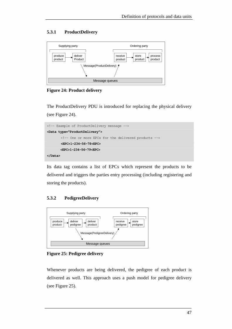
Definition of protocols and data units
5.3.1 ProductDelivery
produceproduct
storeproduct
deliverProduct
processproduct
Message queues
receiveproduct
Supplying party Ordering party
Message(ProductDelivery)
Figure 24: Product delivery
The ProductDelivery PDU is introduced for replacing the physical delivery
(see Figure 24).
<!-- Example of ProductDelivery message -->
<Data type="ProductDelivery">
<!-- One or more EPCs for the delivered products -->
<EPC>1-234-56-78<EPC>
<EPC>1-234-56-79<EPC>
</Data>
Its data tag contains a list of EPCs which represent the products to be
delivered and triggers the parties entry processing (including registering and
storing the products).
5.3.2 PedigreeDelivery
produceproduct
storepedigree
deliverproduct
Message queues
receivepedigree
Supplying party Ordering party
Message(PedigreeDelivery)
deliverpedigree
Figure 25: Pedigree delivery
Whenever products are being delivered, the pedigree of each product is
delivered as well. This approach uses a push model for pedigree delivery
(see Figure 25).
47

Definition of protocols and data units
<!-- Example of a PedigreeDelivery message. -->
<Data type="PedigreeDelivery">
<Graph>
<!-- A node represents a party and the handled product (EPC) -->
<Node managerId="2" EPC="1-2-66-77">
<!-- Key/value pairs, containing inline product data, which the
handling party has chosen to include -->
<Info>
<Entry key="temperature" value="-8"/>
</Info>
<!-- Denotes the predecessing parties and products, which this
product is made of. -->
<Relation type="back" managerId="1" EPC="1-1-44-55" />
</Node>
<Node managerId="1" EPC="1-1-44-55">
<Info>
<Entry key="temperature" value="-8"/>
</Info>
<!-- No Relation is present, so this is a raw supplier -->
</Node>
</Graph>
</Data>
5.3.3 PedigreePropagation
storeproduceproduct
deliverproduct
Message queues
Producing partySupplying parties
Messages(PedigreePropagation)
deliverpedigree
propagatepedigreetriples
storereceive store
Figure 26: Pedigree propagation
This PDU contains a pedigree fragment to be transported backwards in the
supply network to inform past parties (see Figure 26), that one of their
products has become part of a new aggregate. The fragment is a triple of
nodes (see chapter 6.1 for details) that is packed into a graph tag for reasons
of easy parsing and processing.
<!-- Example of a PedigreePropagation message. -->
<Data type="PedigreePropagation">
48

Definition of protocols and data units
<Graph>
<!-- Node which shall be added to the pedigree as new aggregate
("node-to-add") -->
<Node managerId="3" EPC="1-3-99-111">
<Relation type="back" managerId="2" EPC="1-2-66-77" />
</Node
<!-- Node of the pedigree to which the aggregate shall be added ("node-
to-search") -->
<Node managerId="2" EPC="1-2-66-77">
<Relation type="back" managerId="1" EPC="1-1-44-55" />
</Node>
<!-- Current node of pedigree which shall be further completed ("pedi-
gree-to-search") -->
<Node managerId="1" EPC="1-1-44-55">
</Node>
</Graph>
</Data>
5.4 Data Query Protocol
Data which has accumulated within parties during the production process
and product movement can be accessed via the Data Query Protocol. There
exist two methods of querying.
5.4.1 Querying pedigrees
X Manager
sendpedigree(or error)
Message queues
Message(PedigreeRequest)lookuppedigree
receive pedigree query
Message(PedigreeResponse)
Pedigree holding party
Figure 27: Querying pedigrees
Querying pedigrees (see Figure 27) consists of sending a PedigreeRequest
message out into the network. The address of the pedigree holding party is
determined by the EPC's manager identifier.
49

Definition of protocols and data units
<!-- Example of PedigreeRequest Message -->
<Data type="PedigreeRequest">
<!-- EPC of product to query pedigree for -->
<EPC>1-234-56-78<EPC>
</Data>
After the party has received the request and looked up the pedigree, it creates
a corresponding PedigreeResponse message. It contains the pedigree in the
form of a graph tag, which has the same format as the one already presented
in chapter 5.3.2. Note that when using a wildcard EPC for requesting a
pedigree, the data tag can contain more than one graph child tag. Pedigrees
can be visualized in various formats. This thesis uses an existing graph
visualization framework [JUN07] for rendering pedigrees as directed graphs
with inline information shown as tooltips (mouse-over effects).
5.4.2 Querying remote information
X Manager
sendinfo(or error)
Message queues
Message(InfoRequest)lookupinfo
receive info query
Message(InfoResponse)
EPC processing party
Figure 28: Querying remote information
InfoRequest messages are used to retrieve data that a particular party holds
on a certain EPC (see Figure 28). Retrieving information needs an explicit
statement of the parties identifier, which should get the request handed over.
This is different to querying pedigrees. It cannot be determined simply by
using the EPC's management identifier part because more parties than the
managing party can hold information on a certain product. Request messages
are similar to those when querying a pedigree. So they are not repeatedly
presented here. An example of the corresponding InfoResponse message's
data tag is shown below. It contains an errorcode together with a list of info
50

Definition of protocols and data units
tags. More than one of those tags can appear when the InfoRequest was
issued using a wildcard EPC. Each info tag contains key/value property
pairs.
<!-- Data tag value of InfoResponse message -->
<Data type="InfoResponse">
<!-- Errorcode, in case no information can be returned -->
<Errorcode>000<Errorcode>
<Info epc="1-1-1-1">
<!-- A list of keys/value pairs -->
<Entry key="temperature" value="-8"/>
</Info>
</Data>
The application of the protocols mentioned in this chapter results in party
interaction and in subsequent pedigree construction. In order to make the
technique of pedigree construction on the product trail clear, the following
chapter will give a definition of the pedigree structure and classify its
different nodes. It will also give a step-by-step example on pedigree
construction in the forward and the backward direction. After that it will
have a look at the communication effort resulting from that construction
technique and how the supply network's structure and the communication
effort are related.
51
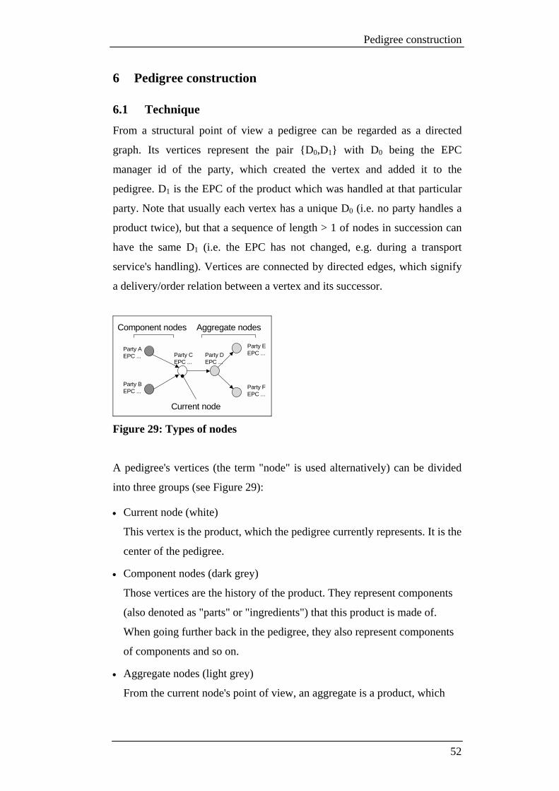
Pedigree construction
6 Pedigree construction
6.1 Technique
From a structural point of view a pedigree can be regarded as a directed
graph. Its vertices represent the pair {D0,D1} with D0 being the EPC
manager id of the party, which created the vertex and added it to the
pedigree. D1 is the EPC of the product which was handled at that particular
party. Note that usually each vertex has a unique D0 (i.e. no party handles a
product twice), but that a sequence of length > 1 of nodes in succession can
have the same D1 (i.e. the EPC has not changed, e.g. during a transport
service's handling). Vertices are connected by directed edges, which signify
a delivery/order relation between a vertex and its successor.
Current node
Component nodes Aggregate nodes
Party AEPC ...
Party BEPC ...
Party CEPC ...
Party DEPC ...
Party EEPC ...
Party FEPC ...
Figure 29: Types of nodes
A pedigree's vertices (the term "node" is used alternatively) can be divided
into three groups (see Figure 29):
• Current node (white)
This vertex is the product, which the pedigree currently represents. It is the
center of the pedigree.
• Component nodes (dark grey)
Those vertices are the history of the product. They represent components
(also denoted as "parts" or "ingredients") that this product is made of.
When going further back in the pedigree, they also represent components
of components and so on.
• Aggregate nodes (light grey)
From the current node's point of view, an aggregate is a product, which
52

Pedigree construction
contains the current node, or another aggregate of the current node as a
component. It therefore represents the "future" of the current node.
When a pedigree is in storage at a party, it is named by the EPC identifier of
the pedigree's current node at this party. That current node has component
nodes, which represent the components of the product (they were
constructed from the received component pedigrees). Those component
nodes will never change again. At production time no aggregate nodes exist
in the pedigree. They will be added to it one by one, when the product (not
necessarily with the same EPC) further travels through the supply network
and the party receives pedigree propagation notifications.
6.1.1 Construction steps
Every party in the supply network has to implement the following behaviour
for doing proper pedigree construction:
1.) On reception of a pedigree, store it for later retrieval so that it can be
looked up by the pedigree's current node's EPC (D1 entry). This
pedigree is referred to as "component pedigree" PC1 and its current
node as NC1.
2.) When a new product is created, create a single current node NP1,
representing the new product, as well.
3.) Create the new product's pedigree PP1 by connecting the current node
of PC1 - PCn (for each component 1-n) as childs to NP1.
4.) Create for each node XP1 from PP1 triples of nodes {NP1, NX, XP1},
which are used for backward data movement, where NX denotes the
current node of PP1's component pedigree (direct childs of NP1), in
which XP1 lies. Those triples are sent to the parties, as stated in XP1's
D1 entry.
NP1: tells the receiver, which new aggregate to add ("node-to-add")
NX: tells him what pedigree to search ("pedigree-to-search")
XP1: tells him, to which node of the pedigree he must attach NP1
("node-to-search")
53

Pedigree construction
5.) Deliver pedigree PP1 to the party, which ordered product P1.
This behaviour should become clear by looking at the following example for
the production of products at parties A, B, C, D, E and F (see Table 2).
t12:Propagationfrom Fto A, B, C, D
t11:Productionat F
t10:Propagationfrom E to A, B, C, D
t9:Production at E
t8:Deliveryfrom D to F
t7:Deliveryfrom D to E
t6:Propagationfrom D to A, B, C
t5:Productionat D
t4:Deliveryfrom C to D
t3:PropagationFrom C to A, B
t2: Production at C
t1: Deliveryfrom A,B to C
t0: Production at A and B
FEDCBAStep Party
A B
A
B
A B
A
BC
A B
B CA CA
BC
A
BC
A
BCA C B C
A
BC D
A
BCA C B C
A
BC D
A
BC DA C D B C D
A
BC D
A
BC DA C D B C D
A
BC D
A
BC D
A
BC DA C D B C D
A
BC D E
A C D E B C D EA
BC D E
A
BC D E
A
BC D E
A C D E B C D EA
BC D E
A
BC D E
A
BC D E
A
BC D
A
BC DA C D B C D
A
BC D
A
BC D
A
BC D
A
BC D F
A
BC D
A C DE
FB C D
E
F
A
BC D
E
F
A
BC D
E
F
A
BC D E
A
BC D F
Table 2: Pedigree construction example
The colouring scheme is the same as the one used in Figure 29. Note that
vertices are just labelled with the parties EPC manager id (D0) and no EPC
(D1) is assigned. This is done for visualization reasons. D1 can be assumed to
54

Pedigree construction
change at every party. How propagation works and how the triple of nodes
{NP1, NX, XP1} is constructed will become clear by looking at Table 3, where
step t10 from Table 2 is shown in more detail.
Result at D:
Triple for D:
Result at C:
Triple for C:
Result at B:
Triple for B:
Result at A:
Triple for A:
Before t10:
FEDCBAStep Party
A C D B C DA
BC D
A
BC D
A
BC D E
A C D E
B C D E
A
BC D E
A
BC D E
E A D
E B D
E C D
E D D
Table 3: Propagation in detail
Pedigree propagation updates parties in the product's history with
information about the product's future in terms of handling party and
assigned EPC ({D0,D1}). Every pedigree has the two fundamental
characteristics:
• It contains all components (each tuple {D0,D1}) of the product.
• It contains all future aggregates (each tuple {D0,D1}) of the product.
55

Pedigree construction
6.2 Communication effort
The supply network will be divided into two halves - the upstream half (this
covers all parties between raw material suppliers and last manufacturer) and
the downstream half (covering parties between last manufacturer and
customers) because communication effort for pedigree handling there is
quite different.
Three assumptions are made for reasons of simplicity:
• There is one single manufacturer in place, which handles all products
before they are transferred to the downstream half of the network. This
manufacturer forms the root of the upstream tree and will be called
"center".
• The upstream half is assumed to be symmetrical to a horizontal axis of
reflexion and all leaves of the upstream tree are of the same distance from
the tree's root.
• Nodes in pedigrees are of roughly the same size. This means that no inline
information is contained.
Different downstream layouts have to be studied and so parameters for these
layouts need to be defined. Especially depth and breadth of the tree are
important related parameters. The so-called "spreading factor" (SF) is
introduced and denotes how many successors each node in the upstream tree
has (except of the leaf nodes). This directly affects depth and breadth of the
layout.
While varying the spreading factor, the total number of handling parties shall
remain the same for each layout. This makes results comparable.
6.2.1 Upstream
Upstream layouts shall be symmetric with the same number of parties while
varying the spreading factor. Not all spreading factors are candidates for
investigation for they have no such layout with the defined total number of
parties.
When defining this total number to be between 110 and 126 (close enough to
do a reasonable examination), four spreading factors qualify:
56

Pedigree construction
SF Depth Parties 1 126 126 2 6 126 3 4 120 10 2 110
Table 4: Overview of SF, depth and parties in upstream
Calculating the parties from the spreading factor and depth was done using
the following formula:
∑=
=1i
depth
iupstream SFparties
Formula 1: Determining total parties in upstream
The total number of pedigrees flowing in the upstream is equal to the
number of parties because each party generates one pedigree and hands it on.
What is important to take into account is the fact that pedigrees are
connected in parties and get further completed. This makes them grow step-
by-step with the speed of growth strongly depending on the tree layout.
The formula for calculating the total amount of pedigree data flowing from
leaves to the center is:
∑ ∑= =
=depthi ij
depth
jtotalpedigree SFdata
1,
Formula 2: Determining total pedigree data in upstream handling
Things are different for propagation messages in the backward direction. A
propagation message's size remains constant (usually containing a pedigree
snippet of 1 node and some additional identifiers). The total amount of
propagation data can be calculated using Formula 3:
∑ ∑= =
∗=depthi ij
depth
jtotalnpropagatio SFsizedata
1,
Formula 3: Determining total propagation data in upstream handling
57

Pedigree construction
This shows that propagation data sent backwards in the chain is size times
the amount of pedigree data because for each pedigree that leaves a party,
each of the contained parties gets propagated a notification for attaching to
their locally held pedigrees. A single propagation contains the node to
propagate and some additional info (the identifiers for "pedigree-to-search"
and "node-to-search"). So the size factor is between almost 1 and 3
8001
642 426 2100
2000
4000
6000
8000
10000
SF = 1 SF = 2 SF = 3 SF = 10
spreading factor (SF)
data Data
Figure 30: Pedigree/propagation data for different spreading factors
The total amount of data to flow through the upstream during product
handling there strongly depends on the tree depth/SF as Figure 30 clearly
signifies. The broader the upstream layout is, the smaller the amount of data
gets.
6.2.2 Downstream
Things are different for the downstream half of the supply network because
one product (and its pedigree) moves on a single trail from the last
manufacturer to the endpoint of the supply network (usually a customer or
the last shop). It is therefore the distance between the last manufacturer
(center) and the endpoint which affects the communication effort. This
distance is denoted as dist(center,endpoint) and used in the short cut form
dist in the following.
So parties in the downstream on the trail between center and endpoint handle
dist pedigrees and create a total amount of pedigree data according to the
following formula:
58

Pedigree construction
∑=
+=0
,
i
distcentertotalpedigree iVdata
Formula 4: Determining total pedigree data in downstream handling
With |V| being the number of vertices of the pedigree right on leaving the
center.
The amount of propagation data is determined in a similar way:
∑=
+∗=0
,
i
distcentertotalnpropagatio iVsizedata
Formula 5: Determining total propagation data in downstream handling
Figure 31 below shows the total amount of data generated during
downstream handling in relation to the length of the trail from center to
endpoint. |V| is 126 (pedigree consists of 126 parties) because this number
has been used in the upstream case before. The data columns directly
represent pedigree data. Multiplying it with the size factor reveals the
amount of propagation data. Growth is linear for both cases.
127255
384514
645777
9101044
11791315
0200400600800
100012001400
1 2 3 4 5 6 7 8 9 10
dist(center,endpoint)
data Data
Figure 31: Generated data during downstream handling
It has been shown that the amount of data to be handled during interaction
strongly depends on the network's structure. The following chapter will show
how the pedigree-based data management supports the two real-life
59

Pedigree construction
scenarios product-recall and product tracking from chapter 2. It will do that
by employing the use cases vehicle recall and tracking of products by a
customer. It will show the approaches advantage over following-the-chain
and centralized concepts.
60

Pedigrees in practice
7 Pedigrees in practice
7.1 Case studies
Two case studies are to be presented in the following to prove how pedigrees
perform in practice. The data management approach which relies on
pedigree construction along the supply chain will be examined in terms of
the amount of data that has to be sent along the supply network and will be
compared to a traditional following-the-chain approach. Product tracking
will be examined in terms of the integrated presentation of status query
interfaces over company borders. Please see chapter 2 for an overview of
more use case scenarios. The following case studies were constructed on that
basis.
7.2 Defective part identification and vehicle recall
It has become quite common for car manufacturers to initiate product recalls
due to defective parts which could lead to vehicle malfunction or - even
worse - accidents.
The following situation is constructed:
A customer's vehicle gets involved into an accident because of a broken
chassis. The driver's insurance company initiates an expert's investigation for
the causes of the failure. Soon, a steel bold has been identified. It has broken
just before the accident. Analysis of the material shows that wrong alloy
composition has lead to material fatigue after an extended period of driving
over rough surface.
It is now the challenge to identify the supplier of those error-prone bolds and
to identify all components where one of these bolds was installed and what
their current location is.
For the conventional following-the-chain approach, this means for each party
(starting with the car dealer) to contact its supplier who has delivered the
component, which had the defective bold build in. That supplier in turn
contacts his suppliers and so on. After the supplier has been identified, the
parties actually holding defective components must be informed. For that
purpose the supplier sends messages to his ordering parties, to withdraw
61

Pedigrees in practice
those parts from circulation. Those messages are forwarded along the supply
network.
This approach has some serious drawbacks:
• Lots of request messages must be sent backwards in the chain until the
defective bold supplier is identified, together with the respective responses
in the opposite direction.
• The total time to identify the defective bold supplier is the sum of the time
to send each data and each parties local processing time.
• Parties in the chain that can not be accessed during the backward search
break the whole identification process.
These points all apply to the recall process as well.
Things are different when there are pedigrees in place. The dealer here in
contrast already holds the vehicle's pedigree, which he got delivered just
when he got the vehicle delivered. He can now quickly traverse this pedigree
structure backwards, until the bold supplier is identified and can contact him.
The supplier subsequently returns the pedigree of the bold charge. It contains
all aggregates that have the bolds built in and their current locations. Those
parties can be directly contacted with a notification message to withdraw the
defective products.
Using pedigrees has the following advantages over a following-the-chain
approach:
• Fast lookup of bold supplier with solely local pedigree processing and no
communication effort.
• Direct communication with the supplier in order to receive the bold
charge's pedigree.
• Fast lookup of components or vehicles that have one of the charge's bolds
build in by solely local pedigree processing. Again no messages have to be
sent.
• Parties holding those products can be contacted directly.
To do a comparison of the amount of messages that needs to be sent in each
approach, a very simple supply network structure is assumed. With the root
representing the bold supplier and the four deepest leaves representing
62

Pedigrees in practice
dealers, each having sold a vehicle that needs to be recalled. For the
following-the-chain approach the supply network structure (and therefore the
number of parties along the distribution/production path) directly affects the
number of messages needed for withdrawal. Whereas the number of
messages in the pedigree approach remains constant. Figure 32 shows a
structure which minimizes the following-the-chain approaches withdrawal
messages because there is one single path from the first to the third node.
That results in only two messages to reach that node. The split into four
nodes in done very lately just before the dealer nodes. The vertical cuts show
that 1 +1 + 4 = 6 messages have to be sent before the dealers get the recall
message.
1 1 4
Figure 32: Model (1-1-4) Minimizing structure
Figure 33 presents a medium structure. Here the distribution path is split
right at the first node and again just before the dealer node. The vertical cuts
through the graph show that 2 + 2 + 4 = 8 messages have to be sent.
63

Pedigrees in practice
2 2 4
Figure 33: Model (2-2-4) Medium structure
The structure in Figure 34 maximized the amount because splits are done
very early (in the first 2 distribution steps), so a total of 2 + 4 + 4 = 10
messages have to be sent.
2 4 4
Figure 34: Model (2-4-4) Maximizing structure
Looking up the root from a leaf as the starting point using the following-the-
chain approach results in a total of distance(leaf,root) * 2 messages. This
represents the procedure of finding the defective bold's supplier when
starting from a dealer node. It becomes obvious that the number of messages
needed for identifying the supplier grows linear to the leaf's distance to the
root.
For the pedigree approach, crawling the local pedigree does not result in any
communication. So no messages need to be sent (see Figure 35).
64

Pedigrees in practice
68
1012
14
0 0 0 0 002468
10121416
3 4 5 6 7
distance (leaf, root)
mes
sage
sFollowing-the-chainPedigree
Figure 35: Messages for identifying supplier
After identification has succeeded, the following-the-chain approach makes
it necessary that from the supplier's node (root) the notification has to be sent
to its ordering parties, that withdrawal shall take place. Those parties in turn
forward it to their ordering parties, who got defective components delivered
from them, and so on. The amount of messages depends on the supply
network structure. So it will be examined by using the three selected
structures mentioned before.
Sending withdrawal notifications in the pedigree approach again results in a
network structure independent number of messages, which only depends on
the number of parties holding parts to withdraw.
68
10
4 4 4
02468
1012
A (1-1-4) B (2-2-4) C (2-4-4)
Model
mes
sage
s
Following-the-chainPedigree
Figure 36: Number of withdrawal notifications
Figure 36 shows that withdrawal for the minimal structure (Model 1-1-4) in
the pedigree approach just needs 66,6% of the messages used in following-
the-chain withdrawal. The pedigree approach shows its advantages even
better for the larger models (2-2-4 and 2-4-4). It just needs 50% resp. 40% of
65

Pedigrees in practice
the following-the-chain communication effort. For other layouts, especially
networks with a higher depth, the resulting communication effort reduction
gets even higher.
Remember that all other advantages related to the time needed for party
identification and the failure resistance due to traversing solely local
pedigrees are still in place.
7.2.1 Note on centralized approaches
The following-the-chain and the pedigree approach can both be combined
with purely centralized data management. This means that no individual
parties, but a centralized directory service has to be contacted for the
defective bold's supplier identification and identification of current products
with their location.
Messaging effort with a centralized approach can come close to that of the
pedigree approach but the drawbacks that were already presented in chapter
3.6 should be taken into account. This thesis' decentralized pedigree
handling approach is a better choice when failure-resistance and
performance both during production and the use case just presented shall be
assured.
7.3 Tracking a product in the supply network
When it comes to tracking products during their transition through the
supply network either by the network's parties or any other third party
instances (e.g. customers, authorities), the pedigree approach has the ability
to offer seamless tracking over multiple companies up to the point of final
delivery. The example of tracking a product after final assembly at the
manufacturer will be presented in the following.
A product transitions through several parties, from last manufacturer, over
several transport services, up to delivery at home. One current approach, like
that of the Dell corporation (for tracking computer hardware) is presented in
Figure 37.
66

Pedigrees in practice
Manufacturer(final assembly)
Status websiteStatus scope
update
Transport serviceDeliver
product
Transport serviceDeliver
product
Status website
Status website
update update
link link
customerCheck different status websites
Figure 37: Conventional status website-based tracking
After a product leaves a companies sphere of influence to that of another
party, links to the new place where status information can be queried are
handed on to the customer. The customer in turn has to cope with different
status interfaces. The status tracking chain gets broken and tracking is
impossible when there are parties in place which do not offer any status
information interfaces.
The pedigree approach solves those problems and makes it possible to easily
present the product's delivery status in one single status website (or more
general: a status interface) because the approaches backward propagation
method informs the manufacturer about the product's current status. It is easy
for him to visualize the pedigree it is holding and update it just in time, at the
moment he receives backward propagation messages from parties later in the
chain. Tracking information can be presented in real-time (see Figure 38).
67

Pedigrees in practice
Manufacturer(final assembly)
Status websiteStatus scope
update
Transport service
DeliverProduct
+pedigree
Transport service
DeliverProduct
+pedigree
pedigree
backward propagation
customer Check single status website
Figure 38: Integrated tracking over company borders
This is a convenient simplification because a customer has one single entry
point for checking the product's status and even parties that have no
accessible status interface can publish their information via the propagation
method.
68

Conclusion and future work
8 Conclusion and future work This thesis introduced the concept of product pedigree flows that accompany
product flows inside supply networks and showed a technique how these
pedigrees can be constructed.
Pedigree construction along the product path accumulates a product's
history.
Propagation backwards in the chain updates parties about a product's future.
Pedigrees are designed to contain inline information. Alternatively remotely
held data can be accessed through a query protocol.
The concept follows a decentralized peer-based approach and avoids the
need for performance-degrading and failure-prone centralized services.
An exemplary supply network has been constructed as a proof of concept
and has been simulated on top of the existing P2PNetSim platform.
This thesis' data management concept has been compared to common
following-the-chain approaches in terms of communication effort and
failure-tolerance. It has proven to be superior to those approaches by
examining identification and recall speed in the context of product recall and
interface integration for product tracking.
Especially security-related use cases like product authentication and
containment of illicit trade are actual challenges which this thesis did not
deal with.
The supply network simulation and the pedigree concept can be taken as a
basis for developing future security mechanisms because extensible XML-
based communication protocols are offered. This makes the way free for
implementing security and product authentication related features, like
pedigree integrity checks, pedigree validation and revocation, in future work.
69

Appendix
A Appendix
Contents
A.1 Supply network structure .............................................................. 71
A.2 Resource CD.................................................................................... 74
70

Supply network structure
A.1 Supply network structure
This appendix contains the content of the supply network configuration file
which was used to simulate this thesis' supply network.
<?xml version="1.0" encoding="UTF-8"?>
<SupplyNetwork>
<!-- The raw material suppliers (R). They have no suppliers.
The genEPC parameter indicates, that they issue their
own EPC codes. Also, the "total" parameter is specific to
peers of type R.-->
<Party name="Raw Supplier 1" managerId="1" ip="1.0.0.1" type="R"
total="100" genEPC="true" gui="true"/>
<Party name="Raw Supplier 2" managerId="2" ip="1.0.0.2" type="R"
total="200" genEPC ="true"/>
<Party name="Raw Supplier 3" managerId="3" ip="1.0.0.3" type="R"
total="400" genEPC="true"/>
<Party name="Raw Supplier 4" managerId="4" ip="1.0.0.4" type="R"
total="600" genEPC="true"/>
<Party name="Raw Supplier 5" managerId="5" ip="1.0.0.5" type="R"
total="300" genEPC="true"/>
<!-- The manufacturers (M). Just like type T, S and C, they contain
supplier relationships.-->
<Party name="Manufacturer 6" managerId="6" ip="1.0.0.6" type="M"
genEPC="true" unit="2">
<!-- A supplier tag states the source peer and the size of the
order, together with delivery bunch size and the "needed-
parameter". -->
<Supplier source="1" order="100" bunch="10" needed="1"/>
<Supplier source="2" order="200" bunch="5" needed="2"/>
</Party>
<Party name="Manufacturer 7" managerId="7" ip="1.0.0.7" type="M"
genEPC="true">
<Supplier source="3" order="400" bunch="5" needed="1"/>
</Party >
<Party name="Manufacturer 8" managerId="8" ip="1.0.0.8" type="M"
genEPC="true" gui="true">
<Supplier source="4" order="0" bunch="10" needed="2"/>
<Supplier source="5" order="0" bunch="10" needed="1"/>
</Party >
<Party name="Manufacturer 9" managerId="9" ip="1.0.0.9" type="M"
genEPC="true" gui="true">
<Supplier source="6" order="200" bunch="10" needed="1"/>
<Supplier source="7" order="200" bunch="10" needed="1"/>
71

Supply network structure
</Party >
<Party name="Manufacturer 10" managerId="10" ip="1.0.0.10" type="M"
genEPC="true" gui="true">
<Supplier source="8" order="200" bunch="10" needed="1"/>
</Party >
<Party name="Manufacturer 11" managerId="11" ip="1.0.0.11" type="M"
genEPC="true" gui="true">
<Supplier source="9" order="200" bunch="10" needed="1"/>
<Supplier source="10" order="200" bunch="10" needed="1"/>
</Party >
<!-- The transport services (T) -->
<Party name="Transport Service 12" managerId="12" ip="1.0.0.12"
type="T" genEPC="false">
<Supplier source="11" order="40" bunch="5" needed="1"/>
</Party >
<Party name="Transport service 13" managerId="13" ip="1.0.0.13"
type="T" genEPC="false">
<Supplier source="11" order="50" bunch="10" needed="1"/>
</Party>
<Party name="Transport service 14" managerId="14" ip="1.0.0.14"
type="T" genEPC="false">
<Supplier source="11" order="60" bunch="10" needed="1"/>
</Party>
<!-- The shops (S) -->
<Party name="Shop 15" managerId="15" ip="1.0.0.15" type="S"
genEPC="false" gui="true">
<Supplier source="12" order="10" bunch="5" needed="1"/>
</Party>
<Party name="Shop 16" managerId="16" ip="1.0.0.16" type="S"
genEPC="false" gui="true">
<Supplier source="15" order="20" bunch="5" needed="1"/>
</Party>
<Party name="Shop 17" managerId="17" ip="1.0.0.17" type="S"
genEPC="false" gui="true">
<Supplier source="15" order="20" bunch="5" needed="1"/>
</Party>
<Party name="Shop 18" managerId="18" ip="1.0.0.18" type="S"
genEPC="false" gui="true">
<Supplier source="14" order="20" bunch="10" needed="1"/>
</Party>
<Party name="Shop 19" managerId="19" ip="1.0.0.19" type="S"
genEPC="false" gui="true">
72

Supply network structure
<Supplier source="14" order="20" bunch="10" needed="1"/>
</Party>
<Party name="Shop 20" managerId="20" ip="1.0.0.20" type="S"
genEPC="false" gui="true">
<Supplier source="14" order="20" bunch="10" needed="1"/>
</Party>
<!-- The customers (C) -->
<Party name="Customer 21" managerId="21" ip="1.0.0.21" type="C"
genEPC="false" gui="true">
<Supplier source="15" order="1" bunch="1" needed="1"/>
</Party>
<Party name="Customer 22" managerId="22" ip="1.0.0.22" type="C"
genEPC="false" gui="true">
<Supplier source="18" order="1" bunch="1" needed="1"/>
</Party>
<Party name="Customer 23" managerId="23" ip="1.0.0.23" type="C"
genEPC="false" gui="true">
<Supplier source="18" order="1" bunch="1" needed="1"/>
</Party>
<!-- The X-MANAGER -->
<Party name="X Manager" managerId="99" type="X" ip="1.0.0.99">
</Party>
</SupplyNetwork>
73

Resource CD
A.2 Resource CD
The CD on this page contains all source code, binaries and libraries, together
with a detailed documentation for running and extending the supply network
simulation. It additionally contains a logging output created from a full
simulation run.
74

Bibliography
Bibliography [BER07] Berg, Daniel / Coltzau, Hauke / Sukjit, Panchalee / Unger,
Herwig / Nicolaysen, Jens GM. (2007): PASSIVE RFID TAG PROCESSING USING A P2P ARCHITECTURE. Fernuniversität Hagen. (unpublished working paper)
[BRI06] The European Commission (2006): BRIDGE. Building Radio Frequency IDentification for the Global Environment. European Commission. http://www.bridge-project.eu/
[COL06] Coltzau, Hauke (2006): Specification and Implementation Of A Parallel P2P Network Simulation Environment. Diploma Thesis, University of Rostock.
[CSI05] CSI/FBI (2005): COMPUTER CRIME AND SECURITY SURVEY. Computer Security Institute. http://www.fbi.gov/page2/july05/cyber072505.htm
[DIE07] Diekmann, Thomas / Melski, Adam / Schumann, Matthias (2007): Data-on-Network vs. Data-on-Tag: Managing Data in Complex RFID Environments. Proceedings of the 40th Hawaii International Conference on System Sciences - 2007.
[EP02] The European Parliament and the Council of the European Union (2002): REGULATION (EC) No 178/2002. Official Journal of the European Communities L 31. http://eur-lex.europa.eu/LexUriServ/LexUriServ.do?uri=OJ:L :2002:031:0001:0024:EN:PDF
[EPC04] EPCglobal Inc. (2004): EPC Tag Data Standards Version 1.1 Rev.1.24. EPCglobal Inc. http://www.gs1-germany.de/content/e39/e466/e468/datei/ccg/ 1_epc_tag_data_specification11rev124.pdf
[EPC07] EPCglobal Inc. (2007): EPC Information Services (EPCIS) Version 1.0 Specification. EPCglobal Inc. http://www.epcglobalna.org/KnowledgeBase/Browse/tabid/277/DMXModule/706/Command/Core_Downlaoad/Default.aspx?EntryId=1050
[EPC07b] EPCglobal Inc. (2007): EPCglobal Homepage. EPCglobal Inc. http://www.epcglobalinc.org/home
[FDA04] Food and Drug Administration (2004): Combating Counterfeit Drugs. A report of the Food and Drug Administration. Food and Drug Administration. http://www.fda.gov/oc/initiatives/counterfeit/report02_04.pdf
[FLE01] Fleisch, Elgar (2001): Von der Vernetzung von Unternehmen zur Vernetzung von Dingen. Universität St. Gallen. http://www.m-lab.ch/pubs/WP9.pdf
[FRA06] Franke, Werner / Dangelmaier, Wilhelm (2006): RFID - Leitfaden für die Logistik. Gabler Verlag.
75

Bibliography
[GAO90] United States General Accounting Office (1990): Nuclear Safety and Health. Counterfeit and Substandard Products Are a Governmentwide Concern. United States General Accounting Office. http://archive.gao.gov/d22t8/142684.pdf
[GIL07] Gillert, Frank / Hansen, Wolf-Rüdiger (2007): RFID für die Optimierung von Geschäftsprozessen. Carl Hanser Verlag München Wien.
[GS107] GS1 (2007): The global language of business. GS1. http://www.gs1.org/
[GS107b] GS1 (2007): Tracking&Tracing. GS1. http://www.gs1-germany.de/content/e40/e111
[GDS06] GS1 (2006): The GS1 Global Data Synchronization Network: What you need to know. GS1. http://www.gs1.org/docs/gdsn/gdsn_what_you_need_to_know.pdf
[GTI04] Uniform Code Council (2004): Global Trade Item Number (GTIN) Implementation Guide. Uniform Code Council. http://www.uc-council.org/ean_ucc_system/pdf/GTIN.pdf
[ICE06] Sukjit, Panchalee / Unger, Herwig / Nicolaysen, Jens GM. (2006): ICE - A SELF-ORGANIZING INFRASTRUCTURE FOR A FLEXIBLE SERVICE MANAGEMENT WITHIN SUPPLY CHAINS. Fernuniversität Hagen.
[IFT06] Universität Hohenheim (2006): IT FoodTrace. Universität Hohenheim. http://www.itfoodtrace.de/download/dateien/Flyer_englisch.pdf
[JAD07] TILab S.p.A. (2007): JADE (Java Agent DEvelopment Framework). TILab S.p.A. http://jade.tilab.com/
[JUN07] O'Madadhain, Joshua / Fisher, Danyel / White, Scott (2007): JUNG — the Java Universal Network/Graph Framework. University of California, Irvine. http://jung.sourceforge.net/
[JXT07] Sun Microsystems (2007): JXTA Technology. Sun Microsystems. http://www.sun.com/software/jxta/
[KEL02] Keller, Wolfgang (2002): Enterprise Application Integration. Erfahrungen aus der Praxis. Dpunkt Verlag.
[LOG07] Logistik inside (2007): Definition: Supply Chain Management (SCM). Verlag Heinrich Vogel. http://www.logistik-inside.de/scm/
[MAT03] Mattern, Friedemann (2003): Vom Verschwinden des Computers – Die Vision des Ubiquitous Computing. From: Friedemann Matten (Hrsg): Total Vernetzt. Springer Verlag. pp 1-41. http://www.vs.inf.ethz.ch/publ/papers/VerschwComp.pdf
76

Bibliography
[MAT05] Mattern, Friedemann (2005): Die technische Basis für das Internet der Dinge. From: Elgar Fleisch, Friedemann Mattern (Eds.): Das Internet der Dinge – Ubiquitous Computing und RFID in der Praxis. Springer-Verlag, pp. 39-66. http://www.vs.inf.ethz.ch/publ/papers/internetdinge.pdf
[MIT07] AUTO-ID Labs (2007): RFID and Academic Convocation Online Community. Massachusetts Institute of Technology. http://autoid.mit.edu/cs/
[NYT07] McNeil, Donald G. Jr. (2007): Low-Cost Antimalaria Pill Available. The New York Times Company. http://www.nytimes.com/2007/03/01/health/01malaria.html?ex=1330578000&en=683cd81751691c69&ei=5124&partner=permalink&exprod=permalink
[ONS03] Mealling, Michael (2003): Auto-ID Object Name Service (ONS) 1.0. Auto-ID Center. http://www.gs1-germany.de/content/e39/e466/e468/datei/ccg/ 8_auto_id-ons-1.0.pdf
[PSM05] The Partnership for Safe Medicines (2005): Counterfeit Drugs in Europe. Fact Sheet. The Partnership for Safe Medicines. http://www.safemedicines.org/resources/europe.pdf
[PW06] Roumeliotis, Gregory (2006): A nudge but no push towards RFID from the FDA. PackWire.com. http://www.packwire.com/news/ng.asp?id=68366-fda-rfid-counterfeit-drugs
[RFA05] Radio Free Asia (2005): China’s Product Piracy Rate 'Highest in the World'. Radio Free Asia. http://www.rfa.org/english/news/business/2005/05/19/china_piracy/
[SOF05] The State of Florida (2005): The 2005 Florida Statutes. Chapter 499 (Florida Drug and Cosmetic Act). The State of Florida. http://www.leg.state.fl.us/statutes/index.cfm?App_mode=Display_Statute&URL=Ch0499/ch0499.htm
[STO06] The European Commission (2006): SToP. Stop Tampering of Products. European Commission. http://www.stop-project.eu/
[UNG07] Unger, Herwig / Sukjit, Panchalee (2007): THE UTH-ADAPTIVE MESHBUILDING ALGORITHM FOR RFID-ROUTING. Fernuniversität Hagen. (unpublished working paper)
[UPS07] United Parcel Service (2007): UPS: Tracking Information. United Parcel Service of America, Inc. http://wwwapps.ups.com/WebTracking/OnlineTool
[W3C03] XML Protocol Working Group (2003): SOAP Version 1.2. World Wide Web Consortium (W3C). http://www.w3.org/TR/soap12-part1/
77

Bibliography
[WEH07] Wehking, Karl-Heinz / Siepenkort, André / Rahn, Klaus-Peter (2007): RFID - Systematische Versuche für den zuverlässigen Einsatz in der Logistik. Logistics Journal. http://www.elogistics-journal.de/archiv/2007/4/1017/wehking.pdf
[WSN05] Karl, Holger / Willig, Andreas (2005): Protocols and Architectures for Wireless Sensor Networks. John Wiley & Sons.
78

Statutory Declaration
Statutory Declaration I declare that this thesis is my own work and that I have not used sources or
means without declaration in the text.
Information derived from the published or unpublished work of others has
been acknowledged in the text and a list of references is given.
This thesis was not submitted in the same or in a substantially similar
version, not even partially, to any other institution to achieve an academic
grading and was not published elsewhere.
Eidesstattliche Erklärung
Hiermit versichere ich, dass ich diese Abschlussarbeit selbständig verfasst
und keine anderen als die angegebenen Quellen und Hilfsmittel benutzt
habe.
Die Stellen meiner Arbeit, die dem Wortlaut oder dem Sinn nach anderen
veröffentlichten oder unveröffentlichten Werken entnommen sind, habe ich
in jedem Fall unter Angabe der Quelle als Entlehnung kenntlich gemacht.
Diese Arbeit wurde bisher weder in gleicher noch in ähnlicher Form, auch
nicht in Auszügen, einer anderen Prüfungsbehörde vorgelegt und auch nicht
veröffentlicht.
________________________ ________________________
Signature/Unterschrift Date/Datum
79