masters in environmental engineering integr… · masters in environmental engineering part i |...
TRANSCRIPT

PEDRO LOZA
JUNE 2008
SAND BYPASSING SYSTEMS MASTERS IN ENVIRONMENTAL ENGINEERING

SAND BYPASSING SYSTEMS
MASTERS IN ENVIRONMENTAL ENGINEERING TOC | Table of Contents
June 2008 Revision 0
Pedro Loza 2
Contents 1. Purpose and Background ........................................................................ 6
2. System Classification ............................................................................... 9
2.1. Purpose ............................................................................................................ 9
2.2. Mobility and Flexibility ..................................................................................... 11
2.3. Operating Mode ............................................................................................. 12
2.4. Operating Schedules........................................................................................ 15
2.5. Capacity ........................................................................................................ 16
2.6. Conclusion ...................................................................................................... 17
3. Bypassing Equipment ............................................................................ 19
3.1. Dredging ........................................................................................................ 19
3.2. Transporting .................................................................................................... 25
3.3. Discharging .................................................................................................... 28
4. Worldwide Experience ........................................................................... 31
4.1. Sand Bypassing Systems................................................................................... 31
4.2. Technical Analysis ........................................................................................... 32
4.3. Conclusions .................................................................................................... 35
5. Coastal Processes .................................................................................. 36
6. Site Characterization ............................................................................. 48
7. Design Guidelines .................................................................................. 52
8. References ............................................................................................. 55

SAND BYPASSING SYSTEMS
MASTERS IN ENVIRONMENTAL ENGINEERING TOC | Table of Contents
June 2008 Revision 0
Pedro Loza 3
Table of Figures Figure 1| Dredger discharging sand .................................................................................... 6
Figure 2| Natural sandspit near Aveiro ................................................................................ 9
Figure 3| Eroded beach downdrift of a groin near Tróia ...................................................... 10
Figure 4| Existing structures can provide support for bypassing equipment ............................. 11
Figure 5| Interception-mode plant at Tweed River ................................................................ 12
Figure 6| Detached Breakwaters ........................................................................................ 13
Figure 7| Bypassing scheme at the Indian River Inlet project ................................................. 19
Figure 8| Backhoe ........................................................................................................... 20
Figure 9| Trailing Suction Hopper Dredger ......................................................................... 21
Figure 10| Jet pump operating scheme ............................................................................... 22
Figure 11| Fluidizer generating a trench ............................................................................ 24
Figure 12| Floating pipelines near the shoreline .................................................................. 25
Figure 13| Sand discharge ............................................................................................... 28
Figure 14| Bulldozer reshaping the discharged sediments .................................................... 29
Figure 16| Mesh of the hydrodynamic model of Abu Dhabi ................................................. 36
Figure 15| Longshore transport quantities relative to percentage of days ................................ 47
Figure 16| Jupiter Inlet ..................................................................................................... 49
SAND BYPASSING SYSTEMS
MASTERS IN ENVIRONMENTAL ENGINEERING Part I | General Considerations on Sand Bypassing
June 2008 Revision 0
Pedro Loza 4
Summary Coastal erosion is a growing concern to the decision-makers, politicians. Where the erosive phenomena assume great importance, sand bypassing systems are often an available – if expensive – option to restore, partially or fully, the littoral drift at a given section of the coast.
The main purpose of this project focuses on presenting an adequate basis for the definition and design of reliable sand bypassing systems. Although the engineering aspects of a bypassing plant present high complexity, it is recognized that the crucial stage of design a system is the definition of its layout which in turn relies heavily on the available data. Thus, the project places a strong emphasis on the coastal processes and site characterization that must be taken into account while defining the type and general characteristics of the system to install.
Additionally, the thesis also covers the technical aspects of the bypassing components – dredging, transporting and discharging – as well as some of the most relevant bypassing systems worldwide, exposing some of the good practices and the main issues that have led to the success or downfall of those systems.
Finally, some guidelines for the design of sand bypassing systems are provided, which compile all previous information and could constitute a road book for the early stages of design.

SAND BYPASSING SYSTEMS
MASTERS IN ENVIRONMENTAL ENGINEERING Part I | General Considerations on Sand Bypassing
June 2008 Revision 0
Pedro Loza 5
Sumário A erosão costeira assume uma preocupação crescente nas mentes dos decisores políticos e das
populações ribeirinhas. Em zonas onde é necessário reduzir o impacto da erosão, a solução
poderá passar pela construcão de sistemas de transposição de areias que recuperem, total ou
parcialmente, a deriva litoral.
O principal objectivo deste documento passa pela apresentação de uma base firme para a
definição e projecto de sistemas de transposição de areias. Apesar de os aspectos técnicos da
trasposição de areias serem complexos, é reconhecido que a fase mais crucial do projecto é a
definição do layout que, por sua vez, depende da qualidade da informação recolhida.
Consequentemente, esta tese foca-se nos processos costeiros e na recolha de informação,
necessários para definir com sucesso o tipo e as características do sistema a desenvolver.
Adicinalmente, este projecto também cobre os aspectos técnicos dos componentes de um
sistema de transposição – dregagem, trnasporte e descarga dos sedimentos – bem como os
sistemas mais relevantes a nível internacional, expondo as boas prácticas e os principais
problemas que determinam o sucesso ou insucesso dos sistemas.
Finalmente, apresenta-se uma estratégia para o projecto de sistemas de transposição de areias
que procura compilar toda a informação apresentada nos restantes capítulos e se apresenta
como um roteiro para as fases iniciais do projecto.
SAND BYPASSING SYSTEMS
MASTERS IN ENVIRONMENTAL ENGINEERING Part I | General Considerations on Sand Bypassing
June 2008 Revision 0
Pedro Loza 6
1. Purpose and Background Coastal erosion is a growing concern to the decision-makers and politicians. The development of guidelines that assist in the creation of new environmental policies and specific actions for specific locations along the coastline where changes are more significant assumes renewed importance with every passing day.
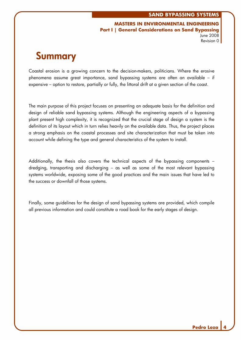
Where the erosive phenomena assume great importance, the primary approach can rely on artificial beach nourishment with seabed sand. Beach nourishment operations frequently assume a periodic character – monthly, annual, biennial – with operating schedules determined by the conjunction of several human and environmental conditions. These operations usually consist of dredging sediments at a given distance from the coast line, pumping them through pipelines and discharging them on the beach or at a small depth, in the surf zone. However, beach nourishment projects are often expensive and non-definitive solutions.
Figure 1| Dredger discharging sand
Sourc
e: h
ttp:/
/ww
w.t
hew
orl
d.a
e/

SAND BYPASSING SYSTEMS
MASTERS IN ENVIRONMENTAL ENGINEERING Part I | General Considerations on Sand Bypassing
June 2008 Revision 0
Pedro Loza 7
When erosion threatens the integrity of populations or important littoral systems, the solution usually stands on the construction of hard coastal defense structures – breakwaters and weirs are some of the most common. However, every obstacle that stands on the coastal line, whether it is natural or man-made, disrupts the sediment transport along the coast, altering the sand budget at that given site.
Man-made coastal defense structures alter the sediment pathways, often inducing and magnifying the erosion and accretion processes at the site, or in nearby beaches. It is common to see large accretion beaches updrift of any obstacle and eroding beaches downdrift.
The littoral drift can also be interrupted by a river inlet. However, in such cases, along with eroding downdrift beaches, another problem arises: the navigation channel may drift and shoals may appear, endangering vessels.
It is common for all problems associated with the interruption of the littoral drift to arise. In fact, it is usual for harbors to induce the erosion of downdrift beaches, accretion on the opposite side and the formation of shoals, hazardous to navigation. These problems may be solved – or prevented – with the installation of mechanical devices able to restore, fully or partially, the interrupted littoral drift.
This project will present several possibilities that may prove to be an adequate basis to the construction of permanent sand bypassing systems, when adapted to different sites. Under the light of worldwide experience, designers realize that no single system will ever solve all the problems associated with the interruption of the littoral drift. As a consequence, a great effort must be put into the geophysical and socio-economic analysis of the site, so that the main issues are taken into consideration during the first stages of design.
Sand bypassing systems operate on simple principles, and consist of dredging, transporting and depositing sand. However, the technical solutions required must attend to the following problems:
− sediments are often lost from the coastal system and the needed amounts are no longer available;

SAND BYPASSING SYSTEMS
MASTERS IN ENVIRONMENTAL ENGINEERING Part I | General Considerations on Sand Bypassing
June 2008 Revision 0
Pedro Loza 8
− the water and sand mixture transported is quite aggressive, both from a mechanical and a chemical point of view;
− the wave climate may render impossible for a dredger to operate unless large sums are attributed to the construction of resistant coastal structures.
As one clearly realizes, these problems appear on the early stages of the bypassing process and are generally associated with the dredging and first phase of sand transport. Each system design will therefore start downstream where fewer variables stand. The main issues related to the transport are associated with the pumping distances needed. Intermediate pumping stations must be considered if demanded.
Decision makers should realize at once that design-build contracts should always be considered, in order to guarantee the best available technical solutions are applied. Bearing this thought, the present study cannot explicit definite solutions, rather proposes specific guidelines to the design of such systems.
This document should stand as a basis for the early stages of the system selection and pre-design tasks. More specifically, the study presents clear guidelines on how to select the best type of sand bypassing system and the most adequate components for each option available. The report concludes with the presentation of different solutions– both in a technical and in an economical aspect – each demanding different levels of commitment and effort.

SAND BYPASSING SYSTEMS
MASTERS IN ENVIRONMENTAL ENGINEERING Part I | General Considerations on Sand Bypassing
June 2008 Revision 0
Pedro Loza 9
2. System Classification For classification purposes, sand bypassing systems have been divided into the following types:
− Purpose; − Mobility / Flexibility; − Operating Mode; − Operating Schedules; − Capacity.
As one can easily understand, in the following classification process some overlapping may occur, since any system may be designed to operate under various conditions. Because it is based not only on system characteristics but on the interrelationship between these characteristics and project conditions and requirements, it deals directly with the problem at hand: choosing the best system for a particular site or situation.
2.1. Purpose
Natural sand bypassing occurs where the longshore sand transport along an open coast travels across inlets in the direction of the net sediment transport. For inlets where the tidal prism of the inlet is small when compared to the transport rate along the coast, a bar will form across the entrance of the inlet to convey sand to the other side.
Figure 2| Natural sandspit near Aveiro
Sourc
e: G
oogle
Eart
h
SAND BYPASSING SYSTEMS
MASTERS IN ENVIRONMENTAL ENGINEERING Part I | General Considerations on Sand Bypassing
June 2008 Revision 0
Pedro Loza 10
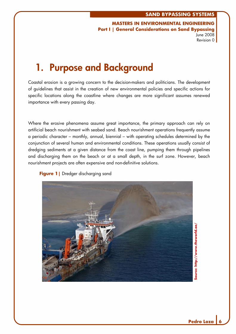
Discontinuities in the shoreline, such as natural or stabilized inlets and harbors interrupt the longshore transport of sediments. However, because such bars can be hazardous to navigation, breakwaters or training walls are often erected along the entrance banks and seawards to stabilize movement of the inlet and to produce new inlets or harbors. While the result may be an improved entrance channel in the short term and safer navigation conditions, the training walls trap the littoral drift so that the updrift beach accumulates against the training wall, whilst the downdrift beach erodes due to a lack of sand supply. In the long term, this process may continue until the sand can once again naturally bypass around the entrance, creating another entrance bar.
Figure 3| Eroded beach downdrift of a groin near Tróia
Sourc
e: G
oogle
Eart
h
Trapping of littoral sediments causes, therefore, two main problems: erosion of downdrift beaches and long-term reduced navigation capabilities.
Artificial sand bypassing, hereinafter referred to as sand bypassing or simply as bypassing, is the man-induced transfer of sand from the jetty fillets, shoals, or navigation channel to the downdrift beaches to mitigate the problems associated with the inlet or harbor. Most sand bypassing operations are done in association with navigation dredging when the sand removed from the navigation channel is placed directly on downdrift beaches or in the nearshore zone.

SAND BYPASSING SYSTEMS
MASTERS IN ENVIRONMENTAL ENGINEERING Part I | General Considerations on Sand Bypassing
June 2008 Revision 0
Pedro Loza 11
2.2. Mobility and Flexibility
To maintain a navigable entrance and neighboring beach amenity, sand bypassing systems have been created to artificially bypass the littoral drift. A number of different systems have been developed around the world. Most systems fall under one or a combination of the following generic types:
− Water-based mobile systems often include maintenance dredging; − Land-based mobile systems; − Fixed systems such as a trestle- or breakwater-mounted.
Figure 4| Existing structures can provide support for bypassing equipment
Sourc
e: h
ttp:/
/pola
ndfo
rall.
com
Mobile systems commonly include all those in which the entire physical plant can be moved and relocated in order to reach various areas of the bypassing site. When floating dredgers are used to capture and deposit sand in a bypassing operation, the system is considered to be mobile and water-based; if a dragline or a jet pump is mounted on trailers the mobile system is an example of a land-based bypassing plant.
Fixed systems are those in which the entire bypassing plant has a set location. Dredger pump systems operating from a building or platform are perfect examples of such plants. Such systems require a high degree of predictability of littoral transport, movement paths and deposition patterns.

SAND BYPASSING SYSTEMS
MASTERS IN ENVIRONMENTAL ENGINEERING Part I | General Considerations on Sand Bypassing
June 2008 Revision 0
Pedro Loza 12
2.3. Operating Mode
Two different operating modes must be considered while defining a bypassing system. When sediments actively move to a certain location and are captured from such site, interception systems can be considered. As an alternative, one or more storage areas can be specifically designed to hold a substantial amount of sand.
Sand bypassing systems may be placed where moving sediment is most likely to be concentrated, and designed to operate on the principle that littoral drift will move to it. Interception-mode systems require a high degree of certainty as to the rate and direction of littoral drift. An interception-mode bypassing system, which may consist of a pump house that moves along a trestle perpendicular to the updrift breakwater, is the type unit located at Paradeep, India. This system is capable of transferring sand at the rate of over 300 m3 per hour, but some littoral drift still moves past the breakwater during storm conditions (USACE 1991, EM 1110-2-1616).
Figure 5| Interception-mode plant at Tweed River, Australia
Sourc
e:
ww
w.t
wee
dsa
ndbypass
.nsw
.gov.
au/
Because these systems are only functional when sediment is moving to it, structures can aid this mode of operation by concentrating and directing sediment to the bypassing system. Because of its obvious limitations, interception-mode systems must be capable of operating over a period associated with incoming wave event that represent near peak sediment transport conditions at the site. Thus, the limiting design bypassing rate will depend on the estimated volume of littoral material moving to the system.
SAND BYPASSING SYSTEMS
MASTERS IN ENVIRONMENTAL ENGINEERING Part I | General Considerations on Sand Bypassing
June 2008 Revision 0
Pedro Loza 13
As mentioned, defining the precise location for interception-mode systems demands considerable planning effort, although littoral drift paths are often concentrated in predictable areas along jetties and breakwaters. Positioning a pier-supported bypassing system updrift of a harbor jetty in the area of littoral drift concentration is a tested solution with proven results – systems located in Lake Worth and South Lake Worth Inlet systems provide examples of this concept (ASAEWES 1990, DRP-3-03). However, care should be taken to prevent undermining of the support structure by the bypassing system operating close by. If the littoral drift is not as important when moving along the shoreline as when moving past a structure, an interception-mode system may be placed within the surf zone, perpendicular to the shoreline. Caution should be paid to erosion, immediately downdrift of the interception point as the beach in that location may be deprived of its normal influx of littoral drift. Systems in Nerang and Tweed River Entrances in Australia are perfect examples of such systems (ASAEWES 1990, DRP-3-01).
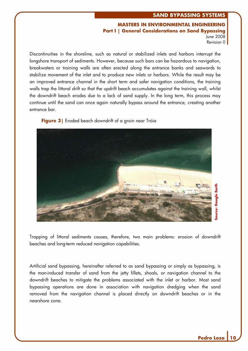
Interception-mode systems usually capture only a portion of the littoral drift and may not be able to handle the sediment influx during maximum littoral drift periods. When designing such a system it may prove better not to design it to handle the infrequent maximum rates, but to create areas that act as temporary storage until the system can catch up, thus maintaining a fairly regular operation. Natural or man-made storage areas may act as traps for littoral drift moving at above-average rates, allowing the accumulated drift to be bypassed later during times of below-average drift rates. Hence, a bypassing system with some storage capacity allows for a more efficient operation schedule.
Figure 6| Detached Breakwaters
Sourc
e: h
ttp:/
/ww
w.e
uro
sion.o
rg/

SAND BYPASSING SYSTEMS
MASTERS IN ENVIRONMENTAL ENGINEERING Part I | General Considerations on Sand Bypassing
June 2008 Revision 0
Pedro Loza 14
If enough storage capacity is provided, such systems can be designed for long-term littoral drift averages and periodic operations at infrequent intervals. Such design directives could provide economic advantage over systems without storage that must handle peak drift rates, but often operate at less than full capacity. Alternatively, sand traps can also allow use of a lower capacity system on a continuous basis.
Additionally, one must consider that during storms, it may not be possible to operate the system because of waves in the storage area or because of danger to personnel; however, sediments accumulated during these periods can be bypassed at other times if they are held at the sand traps.
As mentioned before, structures such as groins, jetties, breakwaters, and weirs can direct sediment to the storage areas, as can natural features. These can be detected using historical information, but should be confirmed by a coastal processes study. Natural sand traps often occur in the form of accretion fillets, bars, deposition basins or channels.
Natural storage areas, such as accretion fillets are quite large, and the effects of bypassing operations may not be very noticeable on their configuration. However, since accretion fillets usually provide wide recreational beaches, resistance by updrift property owners or beach users to bypassing from such locations may be encountered.
As an alternative, river entrances and harbors can be deepened to provide storage capacity. Periodic maintenance dredging of natural or man-made navigation channels can provide sufficient bypassing volumes while avoiding navigation problems from shoaling, although it is usually necessary to dredge the trap below and beyond normal channel limits.
Wave climates may prohibit dredging offshore bars and ebb-tidal deltas. These naturally occurring storage areas contain large quantities of littoral material, but are often poor bypassing system sites because of severe wave environments.

SAND BYPASSING SYSTEMS
MASTERS IN ENVIRONMENTAL ENGINEERING Part I | General Considerations on Sand Bypassing
June 2008 Revision 0
Pedro Loza 15
When considering the deposition of dredged sediments from harbors, thorough analysis of sand characteristics are needed in order to prove these sediments are appropriate to be discharged in downdrift beaches. In fact, because maintenance dredging operations are often required to ensure safe navigation, these operations represent an inexpensive source of sediments. However, prior to the operation, sediments should be analyzed under several criteria – physical, chemical, biological – in order to ensure adequate conditions to the ecosystem and to beach users. Such an approach has been taken successfully at Masonboro Inlet and Carolina Beach Inlet, North Carolina (USACE 1991, EM 1110-2-1616).
Storage areas behind structures can be excellent bypassing sites, because the mild wave climates in these zones can create ideal operating environments. Additional advantages occur when large breakwaters allow great storage capacity and act as a physical base for the bypassing system.
Jetties with weirs can be specially designed to create storage areas. A storage area is formed inside the structure instead of allowing an accretion fillet to accumulate on the outside. This situation produces a very mild operating environment and a potentially large storage area. However, the lower sections needed to allow sediments downdrift of the harbor are often impracticable, since they ensure lesser protection from storms.
A storage-mode bypassing system should be sized according to the area's storage capacity relative to littoral drift influx. In order to guarantee lesser costs, the storage areas must be able to capture and retain littoral material at rates greater than the bypassing system's capacity to remove the trapped material. This condition allows the bypassing system to operate when the littoral transport rates are at a low level and provides for either a continuous operation schedule or a periodic operation at a higher rate of bypassing.
2.4. Operating Schedules
Sand bypassing systems may operate either continuously or on a periodic basis. The first type aims to substitute natural sediment transport along the coast by assuring permanent bypassing. While designing an interception system, a continuous operation schedule should only be considered if the littoral drift rate is near-constant.

SAND BYPASSING SYSTEMS
MASTERS IN ENVIRONMENTAL ENGINEERING Part I | General Considerations on Sand Bypassing
June 2008 Revision 0
Pedro Loza 16
Where the littoral drift rates appear in a wide range of values, the system must handle both storms and lower transfer rates, at economical values. Though it is not impossible to design such a system, it is generally advised to include a storage area when developing a continuous operation bypassing system. As pointed out previously, creating a sand trap allows the design of smaller nominal capacity systems, which are less affected by short-term littoral drift rate variations because of the flexibility provided by the storage area.
Discontinuous or periodic systems usually operate only when bypassing is necessary or a critical point is reached. A dredger that periodically removes sediments that deposited in a sand trap and places the material at a given point, downdrift can be considered an example of such type of systems. In this type of system, the storage area determines the operating schedule.
Regardless of the type of operation schedule chosen, seasonal restrictions caused by social, recreational, or environmental factors may affect the timing of bypassing operations.
2.5. Capacity
The amount of sand bypassed across an inlet or harbor is probably the single most important input when deciding about the construction of these systems.
However, the bypassing capacities of different systems vary greatly, depending on various factors. First, one must consider the amount of sand that is carried to the system. Analyzing the sediment sources available and the littoral drift is crucial to a careful estimate of such values. Tides, waves and storms also affect significantly the amount of sand that reaches the surf zone and is therefore susceptible of being captured by the system.
As pointed out previously, the choice of the system’s operation mode and mobility can also prove to be of crucial importance in order to achieve maximum efficiency. Greater sand bypassing volumes have been registered in the Australian fixed plants, operating continuously. The system located in the Nerang River entrance has been operating since 1986 and has bypassed an average of 500 000m3/year and up to 750 000m3 (Boswood 2001). However, several mobile systems have successfully bypassed volumes of sand greater than 200 000m3/year. It must be mentioned that these average values often correspond to “as needed” dredging operations (Boswood 2001, Clausner 1999).

SAND BYPASSING SYSTEMS
MASTERS IN ENVIRONMENTAL ENGINEERING Part I | General Considerations on Sand Bypassing
June 2008 Revision 0
Pedro Loza 17
While calculating the capacity of a bypassing system, it must be noted that the volume of the dredged sediment is not equal to the discharged volume due to factors of bulkage. In fact, the dredged sand usually has some degree of compaction, with only a small amount of voids. However, because the sediments are mixed with water for transport, the discharged volume will be bigger than the dredged one. While defining the capacity of a bypassing system, the designers must take this factor into consideration. Although the bulkage factor varies with the type of sediment and dredging method, in the early stages it is reasonable to estimate a 10% to 20% increase in the sediment volume between dredging and discharging.
The control of the bypassed volumes differs with the type of bypassing system adopted. In interception systems, the bypassed volume is constantly measured at the pumping facility. These volumes are then topographically/bathymetrically checked periodically at the discharge areas to verify the efficiency of the system. When dredging areas are defined and the bypassing is ensured by mobile systems (dredgers or others), bathymetrical surveys are carried out before and after the operations in both the dredged and discharge areas to verify the actual bypassed sediment volumes.
2.6. Conclusion
Sand bypassing systems have been divided into the following categories:
− Purpose o Reduce Downdrift Erosion / Updrift Accretion o Stabilize a Navigation Channel
− Mobility / Flexibility o Water-based Mobile Systems o Land-based Mobile Systems o Fixed Systems
− Operating Mode o Interception o Storage Areas
− Operating Schedules o Continuous o Periodic
− Capacity o Available Quantities o Operation Mode

SAND BYPASSING SYSTEMS
MASTERS IN ENVIRONMENTAL ENGINEERING Part I | General Considerations on Sand Bypassing
June 2008 Revision 0
Pedro Loza 18
As presented before, sand deficiencies downdrift of inlets can be attributed to various and complex factors, but usually result from the combination of material storage in the inlet or at an updrift obstacle and sediment diversion offshore due to structures. Mechanical downdrift nourishment, using the available littoral drift can prevent beach erosion or shoaling, thus artificially maintaining the sediment flow.
Along this chapter, it has been pointed out that each system type has its own particular characteristics and can be used at different sites. However, worldwide experience shows that the importance of the coastal processes study cannot be empathized enough.
At most sites, the major sand deficit downdrift of an obstacle – breakwaters, inlets, harbors – turns the bypassing capacity the single most important factor on deciding the type of SBS to choose.
However, it is important to mention that a system’s flexibility may prove to be the key to a greater operating efficiency and financial viability of the project. Fixed systems, continuously intercepting sediments, have superior nominal bypassing capacities but are permanently exposed to waves and storms. On the other hand, land- or water-based mobile systems can be sheltered, removed or repaired with greater ease, operating whenever the weather allows. This mobility also grants the system a greater longevity, since they allow for easy adaptation if local conditions gradually change – new storage or accretion areas – with low costs.
Simultaneously, one must point out that designing a bypassing plant can involve the development of a progressive solution. Such an approach often allows for a phased construction, along with a scheduled investment, and the progressive solution of the site’s identified problems.

SAND BYPASSING SYSTEMS
MASTERS IN ENVIRONMENTAL ENGINEERING Part I | General Considerations on Sand Bypassing
June 2008 Revision 0
Pedro Loza 19
3. Bypassing Equipment The following list presents some equipment used in bypassing operations, divided into the different phases of such systems: dredging, transporting and deposition.
Figure 7| Bypassing scheme at the Indian River Inlet project
Sourc
e: P
edro
Loza
, 2006
3.1. Dredging
Collecting sediments from the seabed is the first phase of any bypassing system. Specialized dredging equipment varies widely, coming in many sizes and types, including water- and land-based machines. Dredging equipment, classified according to the methods of excavation and operation, can be grouped into the following main categories:
− Mechanical dredgers; − Hydraulic dredgers; − Other types of dredgers.
The selection of dredging equipment for a particular project will depend upon a combination of factors, including:
− The type of physical environment; − The nature, quantity and level of contamination of the material to be dredged; − The method of placement; − The distance to the placement site.

SAND BYPASSING SYSTEMS
MASTERS IN ENVIRONMENTAL ENGINEERING Part I | General Considerations on Sand Bypassing
June 2008 Revision 0
Pedro Loza 20
Mechanical Dredgers
Mechanical means are used for excavation - dislodging the material and then raising it to the water surface - in a way similar to dry land excavation methods. Barges generally transport mechanically dredged sediments. These dredgers are well suited to removing hard-packed material or debris and to working in confined areas. However, cohesive sediments dredged and transported this way usually remain intact, with large pieces retaining their in-situ density and structure through the whole dredging and transporting process. Therefore, this type of dredger is usually unsuited for bypassing operations, since transport of sediments often occurs over long distances.
Examples of mechanical dredgers include:
− Bucket Ladder Dredgers − Backhoe − Clamshell − Grab Dredgers
Figure 8| Backhoe during dredging works
So
urc
e: h
ttp:/
/ww
w.n
an.u
sace
.arm
y.m
il

SAND BYPASSING SYSTEMS
MASTERS IN ENVIRONMENTAL ENGINEERING Part I | General Considerations on Sand Bypassing
June 2008 Revision 0
Pedro Loza 21
Hydraulic Dredgers
These dredgers use hydraulic centrifugal pumps to provide the dislodging and lifting force and remove the material in a liquid slurry form. They usually work well in loose, "unconsolidated" silts, sands, gravels and soft clays. In materials that are more cohesive teeth or waterjets may be applied for breaking up the material. Hydraulic dredging and transport methods add large amounts of process water and changing the original structure of the sediments. Transport methods associated with hydraulic dredgers include pipeline and hopper transport and allow for transport over greater distances at cost-efficient rates when compared to mechanical dredgers.
Hydraulic dredgers include:
− Cutter Suction Dredgers − Trailing Suction Hopper Dredgers − Stationary Suction Dredgers
Figure 9| Trailing Suction Hopper Dredger
Sourc
e: h
ttp:/
/ww
w.d
csc.
tudel
ft.n
l

SAND BYPASSING SYSTEMS
MASTERS IN ENVIRONMENTAL ENGINEERING Part I | General Considerations on Sand Bypassing
June 2008 Revision 0
Pedro Loza 22
Other Types of Dredging Systems
There are a number of dredging machines that do not readily fit into the above categories, many of which comprise specialized tools developed for specific purposes.
The water injection dredger is a proprietary, patented dredging method. Water injection dredgers pump water into the bed material in order to fluidize it. The material then behaves like a liquid and flows to a lower level.
The punaise ("thumbtack") is a dredger pump system that operates totally below the water surface. Once positioned, the ballast tanks are filled and the punaise settles to the bottom. It is connected to a shore station for communication. The dredged material is pumped through a discharge line.
Jet pumps, also called eductors, do not rely on moving parts in order to physically extract sediments from the seabed. These pumps take a high-energy stream of liquid from a separate water pump, using it to draw in and discharge the material to be pumped.
Figure 10| Jet pump operating scheme
Sourc
e: h
ttp:/
/ww
w.t
wee
dsa
ndbypass
.nsw
.gov.
au/
SAND BYPASSING SYSTEMS
MASTERS IN ENVIRONMENTAL ENGINEERING Part I | General Considerations on Sand Bypassing
June 2008 Revision 0
Pedro Loza 23
Submersible pumps can be an alternative to jet pumps in systems that demand more flexibility. Because of their small size, these pumps can be deployed with little support equipment. Performance is close to jet pumps, with potential transfer rates of 40 to 150 cubic meters per hour (Clausner 1990), in fine to medium sand. However, because of their moving parts – and increased complexity when compared to jet pumps – submersible pumps are susceptible to premature failure of the mechanical seals and require inspection and servicing on a regular basis.
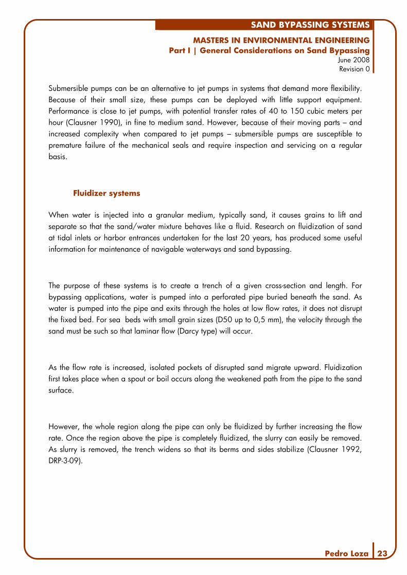
Fluidizer systems
When water is injected into a granular medium, typically sand, it causes grains to lift and separate so that the sand/water mixture behaves like a fluid. Research on fluidization of sand at tidal inlets or harbor entrances undertaken for the last 20 years, has produced some useful information for maintenance of navigable waterways and sand bypassing.
The purpose of these systems is to create a trench of a given cross-section and length. For bypassing applications, water is pumped into a perforated pipe buried beneath the sand. As water is pumped into the pipe and exits through the holes at low flow rates, it does not disrupt the fixed bed. For sea beds with small grain sizes (D50 up to 0,5 mm), the velocity through the sand must be such so that laminar flow (Darcy type) will occur.
As the flow rate is increased, isolated pockets of disrupted sand migrate upward. Fluidization first takes place when a spout or boil occurs along the weakened path from the pipe to the sand surface.
However, the whole region along the pipe can only be fluidized by further increasing the flow rate. Once the region above the pipe is completely fluidized, the slurry can easily be removed. As slurry is removed, the trench widens so that its berms and sides stabilize (Clausner 1992, DRP-3-09).

SAND BYPASSING SYSTEMS
MASTERS IN ENVIRONMENTAL ENGINEERING Part I | General Considerations on Sand Bypassing
June 2008 Revision 0
Pedro Loza 24
Figure 11| Fluidizer generating a trench
Sourc
e: C
lausn
er 1
992
Fluidizer pipes have a maximum effect on fixed bypassing systems operating in intersection-mode. As previously discussed, these systems are generally limited to the amount of sand supplied by littoral drift. Because jet pumps create craters of fairly limited extent, an operator must wait until the crater refills before pumping once again. A fluidizer pipe, used in conjunction with a fixed slurry pump, can create a long (typically 30m to 120m) trench that traps sand across a portion of the littoral zone supplying additional slurry to the pump crater (Clausner 1992, DRP-3-09).

SAND BYPASSING SYSTEMS
MASTERS IN ENVIRONMENTAL ENGINEERING Part I | General Considerations on Sand Bypassing
June 2008 Revision 0
Pedro Loza 25
The system requires fluidizer pipes sloping toward the jet pump crater and water supply pipelines to each fluidizer pipe to carry clear water. Pumps must provide clear water to the fluidizer pipes to work and to avoid clogging the holes.
3.2. Transporting
Transporting sediments depends greatly on the mobility of the system. In a mobile bypassing system, the dredging equipment is often able to carry great amounts of sand to a selected discharge point. Large dredgers can carry several thousands of cubic meters of sand in their hauls and then release them close to shore. However, fixed or continuous bypassing systems require more efficient transporting methods. Pipelines can be an inexpensive means of transporting dredged sand to the discharge point as floating, submerged, or overland conduits and even across or along structures.
Different pipeline materials may be combined at the same project leading to more economical conduits than using one single type of material.
Floating Pipelines
Floating pipelines are usually used at sand bypassing projects utilizing a floating dredger plant. A floating pipeline usually consists of steel (or plastic) pipe sections joined by rubber sleeves or ball joints. The pipe may be supported and raised clear of the water surface, allowing easy inspection and maintenance. Changing the line length involves simply adding or removing some sections. Wave action, however, greatly reduces the reliability of this type of pipeline.
Figure 12| Floating pipelines near the shoreline in Abu Dhabi
Sourc
e: P
edro
Loza
200
7

SAND BYPASSING SYSTEMS
MASTERS IN ENVIRONMENTAL ENGINEERING Part I | General Considerations on Sand Bypassing
June 2008 Revision 0
Pedro Loza 26
Reinforced flexible rubber pipelines with built-in flotation are available, generally for offshore use. The anticipated life of this type of pipeline is greater than steel, but it is considerably more expensive. Floating pipelines are generally positioned at the bypassing site on a temporary basis (in conjunction with floating dredgers) to avoid a prolonged obstruction to navigation.
Submerged Pipelines
Many sand bypassing projects use submerged, buried pipelines to transfer material across navigation channels to downdrift beaches. The line does not interfere with navigation and has no impact on the landscape. Problems associated with submerged pipelines include fluidization of the bed around the pipeline, but can be avoided by an adequate cover depth. Another problem with submerged pipelines is danger of damage from ship or boat anchors and damage from maintenance dredging operations. Burial depths well below authorized channel depths along with warning signs may help to avoid these problems.
Polyethylene Pipelines
Conventional bypassing systems often use rigid steel discharge pipelines. In recent years there has been an increase in the use of high-density polyethylene (HDPE) discharge lines. HDPE is a lightweight, flexible material that, applied properly, will outlast steel discharge lines. The HDPE sections are joined using portable heat fusion machines which heat, and compress the ends of the pipe together to form joints that are stronger than the pipe itself. Pipe sections can also be joined using circle clamps. Steel flanges may also be fitted to the HDPE pipe ends for bolted connections.
Depending on slurry flow rate and concentration, HDPE, on average, is 3 to 5 times more abrasion resistant than conventional steel pipe. The flexibility of HDPE allows pipelines to be bent to radii approximately 25 times the pipe diameter. Flexibility reduces the number of expensive ball joints or other flexible connectors. This, in turn, improves hydraulic efficiency and reduces pumping power requirements. The HDPE has no rusty, corroded appearance (as does steel) and is therefore more aesthetically acceptable at most sites.
However, polyethylene pipes lack the structural rigidity to withstand external loads, bending, and torque; therefore, it should not be considered as suction lines in a bypassing system, since
SAND BYPASSING SYSTEMS
MASTERS IN ENVIRONMENTAL ENGINEERING Part I | General Considerations on Sand Bypassing
June 2008 Revision 0
Pedro Loza 27
these are generally subject to swinging, hoisting, and mechanical abrasions that could crimp and bend the pipe. The fact that HDPE is lighter than water obviously makes installation and handling easier. However, when installed underwater, proper anchoring is necessary, otherwise, HDPE pipes can potentially float upwards. While there are advantages to using HDPE, there are special requirements for its successful use which are quite different from conventional practices for rigid steel lines. Design manuals address such topics as pressure ratings, anchoring, floatation and others. Most suppliers also provide engineering services for applications not specifically addressed in their manuals.
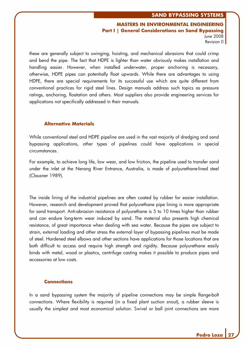
Alternative Materials
While conventional steel and HDPE pipeline are used in the vast majority of dredging and sand bypassing applications, other types of pipelines could have applications in special circumstances.
For example, to achieve long life, low wear, and low friction, the pipeline used to transfer sand under the inlet at the Nerang River Entrance, Australia, is made of polyurethane-lined steel (Clausner 1989).
The inside lining of the industrial pipelines are often coated by rubber for easier installation. However, research and development proved that polyurethane pipe lining is more appropriate for sand transport. Anti-abrasion resistance of polyurethane is 5 to 10 times higher than rubber and can endure long-term wear induced by sand. The material also presents high chemical resistance, of great importance when dealing with sea water. Because the pipes are subject to strain, external loading and other stress the external layer of bypassing pipelines must be made of steel. Hardened steel elbows and other sections have applications for those locations that are both difficult to access and require high strength and rigidity. Because polyurethane easily binds with metal, wood or plastics, centrifuge casting makes it possible to produce pipes and accessories at low costs.
Connections
In a sand bypassing system the majority of pipeline connections may be simple flange-bolt connections. Where flexibility is required (in a fixed plant suction snout), a rubber sleeve is usually the simplest and most economical solution. Swivel or ball joint connections are more

SAND BYPASSING SYSTEMS
MASTERS IN ENVIRONMENTAL ENGINEERING Part I | General Considerations on Sand Bypassing
June 2008 Revision 0
Pedro Loza 28
expensive, but are used where simple flexible sections prove inadequate as where there is risk of a twisting motion.
3.3. Discharging
The point of discharge on the downdrift side of the littoral barrier may be of critical importance to the success of the bypassing operation. However, considerations on where to place the bypassed sand and the equipment needed to spread the sand are essentially independent of the bypassing system or method. Discharge should always take into account the general conditions of sediment transport (USACE 1983, EM 1110-2-5025).
Figure 13| Sand discharge in a project in Abu Dhabi
Sourc
e: P
edro
Loza
200
7
Even in sites where the littoral drift is mainly unidirectional, the discharge point should be a sufficient distance away from the inlet, in order to reduce the possibility of refraction effects from the ebb-tidal delta, which might otherwise direct sediment towards the inlet regardless of wave direction.

SAND BYPASSING SYSTEMS
MASTERS IN ENVIRONMENTAL ENGINEERING Part I | General Considerations on Sand Bypassing
June 2008 Revision 0
Pedro Loza 29
As a first estimate, the designer should determine the location where the nearshore bottom contours become parallel to the shoreline, indicating the point where inlet-dominated processes cease. If this point proves to be at a great distance from the inlet, wave refraction studies should be performed to better define the elimit of refraction effects. An economic balance between cost of longer discharge pumping and amount of sediment returning to the inlet can be made.
It must be noted that the slurry (water/sand mixture) is usually pumped on a 1/3 ratio which means that the discharged material will flow and eventually deposit a certain distance from the discharge point. If the sand is discharged in the surf area as recommended, the waves will distribute the sediments along the shore. If the sediments are deposited on the shore, additional landworks equipment (usually bulldozer or backhoe) are usually required to distribute and shape the bypassed sand (see Figure 14).
Figure 14| Bulldozer reshaping the discharged sediments in Dubai
Sourc
e: h
ttp
://f
arm
2.s
tatic.
flic
kr.
com
/1216/

SAND BYPASSING SYSTEMS
MASTERS IN ENVIRONMENTAL ENGINEERING Part I | General Considerations on Sand Bypassing
June 2008 Revision 0
Pedro Loza 30
In areas with significant littoral transport reversal periods, some of the material at the point of discharge will probably be transported back toward the littoral barrier or into the inlet. Where transport reversals occur, a detailed study should be made of the distribution of littoral forces downdrift of the barrier, in order to keep this reverse transport to a minimum.
Establishing a discharge point in such conditions requires the use of statistical wave data, wave refraction and diffraction diagrams, and data on nearshore currents. Alternative points of discharge nearer the barrier may also be considered, particularly if structural devices such as groins or breakwaters are used to impede updrift movement of material at the discharge point. Such alternative considerations are of value for selecting the discharge point.

SAND BYPASSING SYSTEMS
MASTERS IN ENVIRONMENTAL ENGINEERING Part II | Sand Bypassing Systems Worldwide
June 2008 Revision 0
Pedro Loza 31
4. Worldwide Experience
4.1. Sand Bypassing Systems
Table 1 presents a summary of the bypassing systems analyzed during the data collection phase. The selection of the systems listed below was based on the availability and quality of the data available. More detailed information about these systems can be found in the annexes.
Table 1| Bypassing systems comparison table
Case Name Location Operating
Since Years in
operation Type of System
Bypassing Volumes (m3/yr)
1 Nerang River Entrance Australia 1986 18 Fixed 500000 2 Tweed River Entrance Australia 2001 3 Fixed 700000 3 South Lake Worth Inlet USA 1937 67 Fixed 53500 4 Oceanside Harbor USA 1989 - 1996 7 Fixed 14000 5 Indian River Inlet USA 1990 14 Mobile 91000 6 Lake Worth Inlet USA 1958 46 Fixed 61000 7 Carolina Beach Inlet USA 1965 39 Mobile 122000 8 East Pass USA 1930 74 Mobile N/A 9 Hillsboro Inlet USA 1952 52 Mobile 50000 10 Jupiter Inlet USA 1929 75 Mobile 600000 11 Little River Inlet USA 1983 21 Mobile N/A 12 Masonboro Inlet USA 1959 45 Mobile 215000 13 Ponce de Leon Inlet USA 1969 35 Mobile 535000 14 Santa Barbara USA 1927 77 Mobile 250000 15 Rudee Inlet USA 1972 32 Semi-Mobile 300000 16 Santa Cruz USA 1962 42 Mobile 70000 17 Ventura Marina USA 1972 32 Mobile 600000 18 Port Sanilac USA 1958 46 Fixed N/A 19 Mexico Beach Inlet USA 1971 - 1978 7 Mobile 30000 20 Sebastian Inlet USA 1962 42 Mobile 190000
As reflected in the table above, most of the systems found in the references were built in the USA (and Australia) and account for over 90% of the total number of SBS worldwide. The construction of these systems was initiated in the late 1920’s and resulted from an advance in the engineering techniques which affected all industries and from the idea that man could master and even reshape nature. In the US, during the decades that ranged from the 1930’s to
SAND BYPASSING SYSTEMS
MASTERS IN ENVIRONMENTAL ENGINEERING Part II | Sand Bypassing Systems Worldwide
June 2008 Revision 0
Pedro Loza 32
the 1980’s, the federal government had to allocate vast budgets to build and operate these facilities.
The creation of a SBS is always dependent on a heavy commitment from the funding parties and, in several examples in the US, these systems were validated by the need to maintain an open navigation channel that feeds industrial facilities or wealthy communities, thus justifying the expenses. If a bypassing system does not generate direct revenue, it is quite hard to mobilize the resources required not only to build but also to operate the plant.
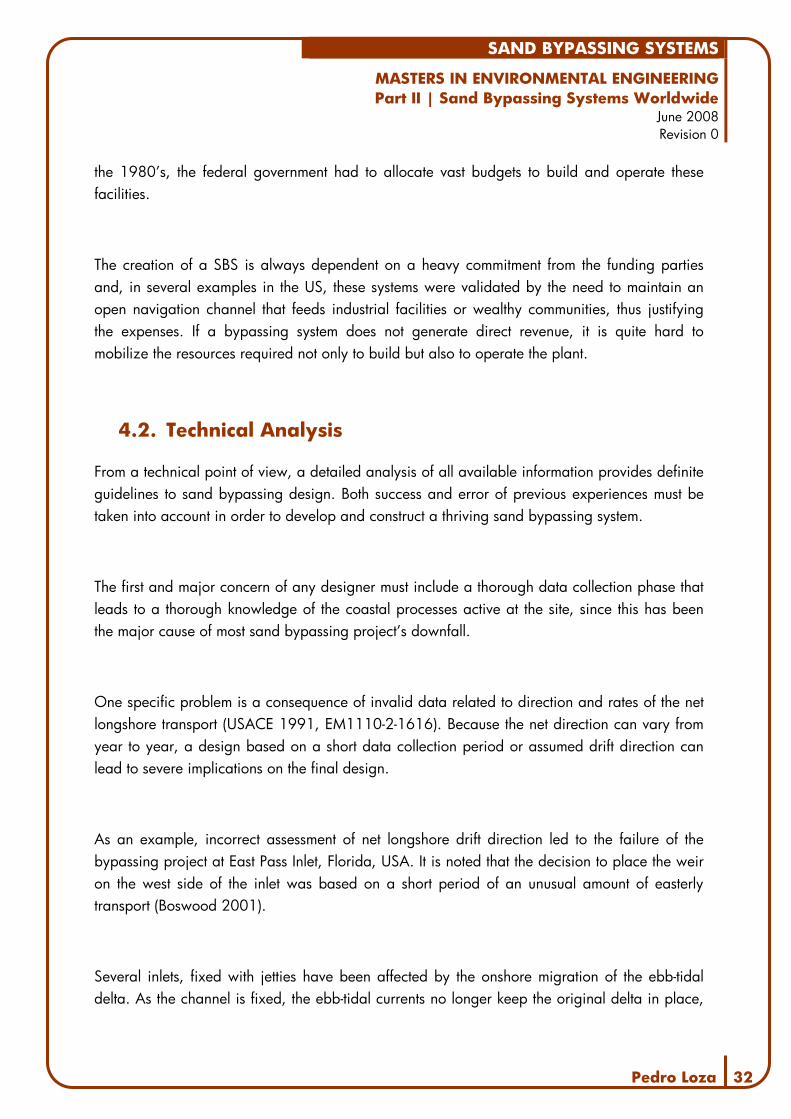
4.2. Technical Analysis
From a technical point of view, a detailed analysis of all available information provides definite guidelines to sand bypassing design. Both success and error of previous experiences must be taken into account in order to develop and construct a thriving sand bypassing system.
The first and major concern of any designer must include a thorough data collection phase that leads to a thorough knowledge of the coastal processes active at the site, since this has been the major cause of most sand bypassing project’s downfall.
One specific problem is a consequence of invalid data related to direction and rates of the net longshore transport (USACE 1991, EM1110-2-1616). Because the net direction can vary from year to year, a design based on a short data collection period or assumed drift direction can lead to severe implications on the final design.
As an example, incorrect assessment of net longshore drift direction led to the failure of the bypassing project at East Pass Inlet, Florida, USA. It is noted that the decision to place the weir on the west side of the inlet was based on a short period of an unusual amount of easterly transport (Boswood 2001).
Several inlets, fixed with jetties have been affected by the onshore migration of the ebb-tidal delta. As the channel is fixed, the ebb-tidal currents no longer keep the original delta in place,

SAND BYPASSING SYSTEMS
MASTERS IN ENVIRONMENTAL ENGINEERING Part II | Sand Bypassing Systems Worldwide
June 2008 Revision 0
Pedro Loza 33
and a portion of it migrates onshore. The extra amount of sand can lead to increased amounts of sand getting into the channel – which may therefore need dredging – or require additional lengths of pipe to reach the surf zone to allow bypassing. This has happened at Ponce de Leon Inlet, Florida, USA; Murrells Inlet, South Carolina, USA; and the Nerang River Entrance, Queensland, Australia (Boswood 2001) (USACE 1991, EM1110-2-1616) (Clausner 1990, DRP-3-03).
The cross-shore distribution of littoral drift is considered to be very important in the design of fixed plants. Data from the Nerang River Entrance confirmed that most sediment transport takes place close to shore. Table 2 presents the number of operating hours for each of the 10 jet pumps (spaced about 30m apart), which roughly corresponds to the amount of sand transferred. Jet pump number 1 is farthest offshore and number 10 closest to shore.
Table 2| Pumping Hours per Jet Pump at Nerang Bypassing System
Offshore (Total 5828) Nearshore (Total 10078) Jet Pump 1 2 3 4 5 6 7 8 9 10 Operating Hours 1085 845 1202 922 1774 1346 1777 2209 2326 2420
Font: Clausner 1990, DRP-3-03
As shown, jet pumps from 6 to 10 were responsible for almost twice as much dredging as the remaining 5, further away from the shore. In fact, and depending on wave activity and the depth of the crater, nearshore craters may take 12 to 36 hours to fill during wave activity. This fact should be taken into account when sorting the location for a deposition basin. Experience has shown that the widest part of the deposition basin should be landward of the weir-shore connection. At Masonboro Inlet, North Carolina, USA, the original deposition basin was expanded to cover a large area that reaches back a considerable distance. By expanding the deposition basin, it has been possible to reduce the dredging frequency from once each year to once every 4 years with a subsequent reduction in costs.
At Masonboro, Murrells, and St. Lucie Inlets, sand is carried over and through a weir into the inlet, forming a small spit at the end of the updrift island where the sediments where taken from (USACE 1991, EM 1110-2-1616).

SAND BYPASSING SYSTEMS
MASTERS IN ENVIRONMENTAL ENGINEERING Part II | Sand Bypassing Systems Worldwide
June 2008 Revision 0
Pedro Loza 34
Weir elevation and length
The Ponce de Leon Inlet weir was 550m long and had no elevation above the medium sea level. This too long and too low weir allowed excess ebb flow over the weir, which encouraged the channel to migrate up against the north jetty. Also, because the weir was too low (a midtide elevation is usually recommended) it allowed an excessive amount of wave energy into the interior of the inlet, causing erosion of the land on the south side (USACE 1991, EM 1110-2-1616).
Jet pump systems like the ones operating on the Nerang River Entrance, or at Oceanside, California, USA provide valuable information regarding fixed bypassing plants (Clausner 1992, DRP-3-05). The jet pump system operated at the Rudee Inlet, Virginia, USA, provides data regarding a semi-mobile jet pump system. It is known that jet pump clogs occurred occasionally, but backflushing proved to be a satisfactory clearing method. Jet pump mobility prevents shutting down the system for long periods due to debris. However, moving the jet pumps and the supply and discharge hoses during rough weather is extremely difficult. Fixed bypassing plants may resort to conventional cutterhead dredgers to avoid or minimize the accumulation of debris in the craters. Because jet pumps dig their own craters, these often collapse over the supply and discharge lines, hindering retrieval and/or movement of the pumps. Another factor to take into account, especially in mobile and semi-mobile systems is that flexible hoses deteriorate rapidly, particularly at end connections.
Debris continues to be the major problem for fixed plant operation. In the Nerang system, large pieces of wood from the adjacent river entrance accumulated in some of the craters severely reducing jet pump performance. A second major debris problem at the Nerang River Entrance has been the dune grass which eroded from the dunes during storms forming large balls and mats in the jet pump craters, effectively preventing sand from reaching the eductor (Clausner 1989, DRP-3-01).
At Oceanside, California, kelp stalks up to 10 meters long have clogged jet pumps in the entrance channel. The potential for debris related problems like those described forces the designer of a fixed plant, especially one with jet pumps, to consider that the eductor needs to be able to be retrieved and deployed easily with onsite equipment. Since the eductor will be placed in an area of active shoaling, plans for retrieving the eductor should include the possibility that the eductor and supply and discharge pipes may be buried by 2 or 3 meters of

SAND BYPASSING SYSTEMS
MASTERS IN ENVIRONMENTAL ENGINEERING Part II | Sand Bypassing Systems Worldwide
June 2008 Revision 0
Pedro Loza 35
sand. A method to remove the eductor and piping should be considered even under these adverse conditions. Alternative methods of removing major debris accumulations (once every 6 months to 1 year) at jet pump locations should be planned (e.g. clamshell, grappling hooks, etc.) (Clausner 1990, DRP-3-03). This means that either the structure supporting the eductor will have to be moved, or the eductor will have to be placed some distance out from the structure. As previously mentioned, as the mobility of the eductor increases, the debris problem is reduced.
Another lesson to be learned is that to provide the bypassing system with more sand, a single eductor will have to be moved at small intervals. Otherwise, multiple pumps will be needed to provide continuous transfer. In fact, offshore craters will remain empty for several weeks after creation unless there is significant wave action. Nearshore craters generally fill in much faster due to increased wave influences at shallower depths. During transfer, these craters may be emptied in a few hours, inducing the operator to constantly move the eductor. Finally, craters in fixed locations will tend to armor the side slopes with coarser material over time, creating even steeper slopes and resulting in smaller crater volumes.
4.3. Conclusions
The construction of sand bypassing systems is usually blocked by budget constrictions and is
rarely considered an option when its construction does not generate revenue. Usually these
systems are only an option where industrial areas, high-end residential zones of touristic
developments are at stake.
From a technical standpoint, there are several lessons to extract from the worldwide experience
in sand bypassing. First, the design team must be provided accurate and reliable data about
the site and the physical conditions that affect the project. As mentioned before, one of the most
common mistakes involves using data collected over a short period leading to a misconception
of how the coastal systems behave and evolve. When designing intersection type bypassing
systems or sand-traps, the cross-shore distribution of the littoral drift is also crucial.

SAND BYPASSING SYSTEMS
MASTERS IN ENVIRONMENTAL ENGINEERING Part III | System Design Guidelines
June 2008 Revision 0
Pedro Loza 36
5. Coastal Processes
As noted before, when sand bypassing systems fail it is often due to insufficient knowledge of the coastal processes present at that specific site. Naturally, a detailed data collection phase, followed by a thorough coastal processes study is critical to a successful bypassing operation or system. This section summarizes how coastal events such as tides, sediment transport or waves should be included in the scope of the coastal study and how they should influence the design process of a sand bypassing system.
Before a bypassing project is initiated, an overview of the coastal system should be compiled. In recent years, there has been a tendency to give more emphasis to regional sediment management. This approach could imply looking at sediment management over lengths of coast that includes various inlets can be hundreds of kilometres long. Within this framework, sand bypassing becomes a key concept, since improved sand bypassing at inlets may provide significant benefits to the region as a whole and not just for a single inlet (Clausner 1999).
Numerical modelling constitutes a powerful tool in the assessment of the coastal system’s evolution. The most powerful and complete models commercially available, developed by DHI, Delft Hydraulics and SOGREAH provide a wide array of input parameters, use meshes of finite differences and finite elements, resort to 2D or 3D resolution of the hydrodynamic equations and usually provide reliable outputs.
Figure 15| Mesh of the hydrodynamic model of Abu Dhabi
Sourc
e: P
edro
Loza
2007

SAND BYPASSING SYSTEMS
MASTERS IN ENVIRONMENTAL ENGINEERING Part III | System Design Guidelines
June 2008 Revision 0
Pedro Loza 37
However, any of these models have limitations, usually related to their complexity. In fact, any of the three institutions mentioned above provide dedicated training programs to ensure the users have an adequate knowledge of the software. In fact, a slight change in any of the thousands of parameters that a given model can have as input will produce results that are equally reasonable, but totally distinct.
The main problem associated with the use of numerical models is related with the accuracy of the input data. Any model will provide output based on the information that is given as input. Countless times, bad quality data is the base for complete studies that will be limited from the start.
An alternative to numerical models will always be physical modelling. Conducting tests in scaled-down models will always provide a more reliable feedback than the computer models. Physical models also require very experienced personnel, up-to-date facilities and state-of-the-art equipment. Additionally, these models always need bigger budgets and longer timeframes to be used.
In any of the cases, one can never stress enough the crucial importance of a good data collection campaign. Tides, waves, winds, aerial photographs, sediment transport, bathymetry, geotechnical characteristics. All of these play a critical role in the success of a coastal project as complex as a sediment bypassing system.
Sediment Budget
A sediment budget is a volume balance representing sediment exchange for a specific section of the coast. In sand bypassing design, it is usual to consider that the littoral zone extends from the shoreline to just beyond the breaker zone.
In order to accurately quantify the sediment budget at a given site, the designer is required to gather full knowledge of the sources, transport mechanisms, and deposition rates for the area. More specifically, sediment budget estimation demands a quantification of the longshore

SAND BYPASSING SYSTEMS
MASTERS IN ENVIRONMENTAL ENGINEERING Part III | System Design Guidelines
June 2008 Revision 0
Pedro Loza 38
sediment transport, erosion, and accretion for a control area. A sediment budget analysis should also include onshore/offshore transport, wind-blown losses and gains, and man-made changes within the control volume, such as beach nourishment and sand mining.
To help separate natural from man-induced changes in the littoral cell, the sediment budget can be estimated for pre-historic periods as well as for historic and recent periods. By examining the sediment budget from various time periods, it is possible to compare the natural evolution and variability in the system to changes forced by human intervention.
As noted previously, sediment-transport pathways and patterns of sediment accumulation in the littoral cell are not static, but change over geological, historical, and seasonal time scales. Some changes in the sediment budget are the result of natural cycles such as long-term changes in sea level, or of short-term fluctuations such as in wind and wave directions. Other changes in pathways and sinks in the sediment budget are the result of human influences, such as the construction of jetties, or dredging practices.
It must also be taken into account that rivers and ebb-tidal deltas may act as temporary sources of sediments. These sources must be thoroughly considered because they induce short-term changes on the amount of sand brought into the coastal systems.
It is also important to point out that sediment supply from rivers to their estuaries have often been reduced throughout the world over the last several decades due to reduction in transport capacity resulting from flow regulation, and possible direct trapping behind dams.
Several sand bypassing systems have failed due to errors in the evaluation of sediment budgets. However, there is a persistent misconception among both land managers and researchers that the construction of sediment budgets is a time-consuming, academic exercise that is impractical for addressing the goals of land-use planning or short-term research. Although sediment budgeting often uses long-term measurements, budgets can also be constructed using rapid measurements and estimates to provide results at a level of precision adequate for most management needs. One of the reasons why sediment budgets are mistakenly viewed as impractical for short-term analyses is partly because the utility of approximate budgets is often overlooked (EM 1110-2-1204, USACE).

SAND BYPASSING SYSTEMS
MASTERS IN ENVIRONMENTAL ENGINEERING Part III | System Design Guidelines
June 2008 Revision 0
Pedro Loza 39
A second misunderstanding arises because erosion and transport rates are difficult to measure precisely, accurately, and consistently. Erosion is perceived as being intractably variable and complex, and lengthy measurement periods are assumed to be necessary if monitoring is to produce a meaningful average erosion rate. However, it is possible to design simple sampling schemes that account for seasonal and local variations in process rates if the reasons for these variations are understood. In addition, most management applications require only that the order of magnitude or the relative importance of process rates be known (EM 1110-2-1616, USACE).
A third misconception focuses on the notion that sediment budgeting implies construction of detailed maps of erosion processes. Management problems usually involve areas that are too large to permit thorough examination either in the field or on aerial photos, thus making comprehensive mapping impractical and sediment budgeting assumed to be impossible. However, construction of budgets for large areas merely requires a modification of techniques. Large areas can be divided (“stratified”) into subunits of similar soils, bedrock, vegetation, topography, and land use, and each subunit is characterized by budgets constructed for representative areas within it (EM 1110-2-1616, USACE).
A simple approach to the construction of approximate sediment budgets stands on acquiring background information and subdividing the study area when necessary. A careful interpretation of aerial photographs, cross-checking the results with the necessary fieldwork may be required.
Because of the very nature of sand bypassing operations, preparing a complete sediment budget is the most crucial product of the coastal processes study. When performing a sediment budget, sediment sources and sinks are identified, and the transported amounts are determined. Results from the sediment budget calculation will determine bypassing rates, and locating sediment sinks can help to identify possible sites for bypassing. This budget is the core of a SBS design, since it describes the volume of sand and the frequency of the bypassing operations.
To evaluate bypassing system performance, it will be necessary to compute a new sediment budget once the bypassing system is in operation. This post bypassing sediment budget should
SAND BYPASSING SYSTEMS
MASTERS IN ENVIRONMENTAL ENGINEERING Part III | System Design Guidelines
June 2008 Revision 0
Pedro Loza 40
result from a continued coastal processes monitoring program. The monitoring effort should be scaled down from the coastal processes information necessary for design, but would need to include bathymetric and/or profile surveys over the bypassing site boundaries. A post bypassing sediment budget will indicate system effectiveness and help in operational adjustments, such as intake and/or discharge locations. Long-term performance of the system can be evaluated with a series of sediment budget calculations.
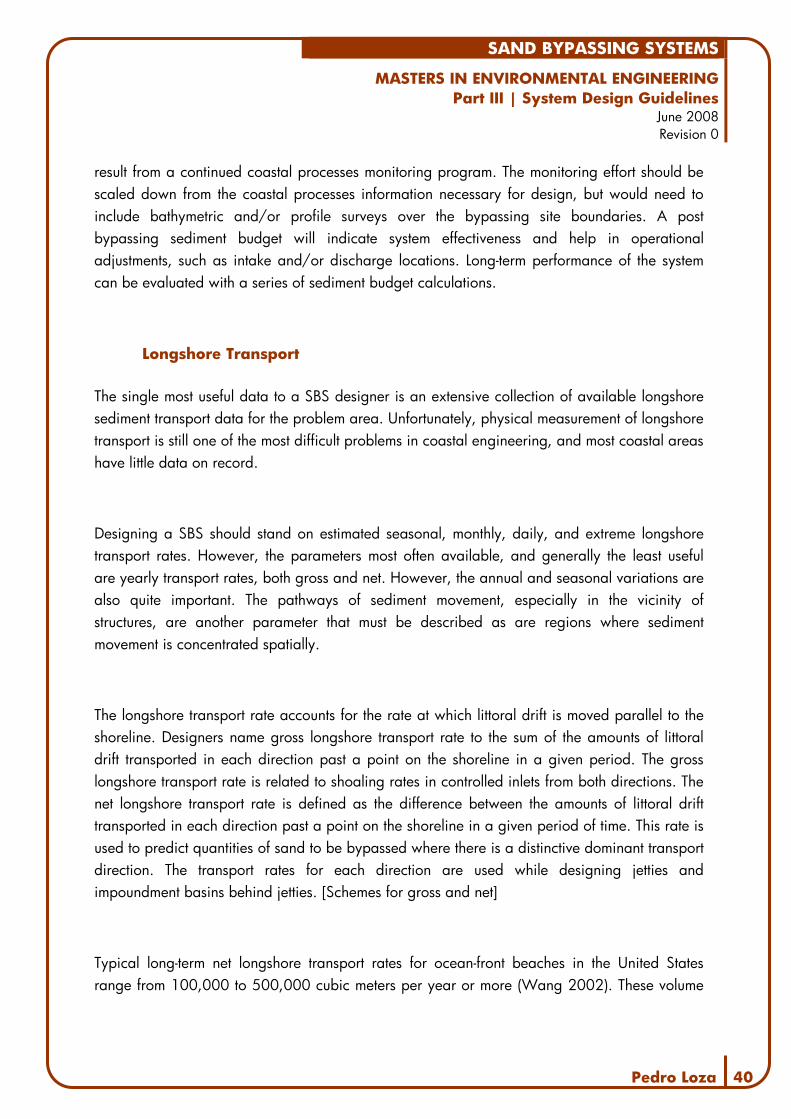
Longshore Transport
The single most useful data to a SBS designer is an extensive collection of available longshore sediment transport data for the problem area. Unfortunately, physical measurement of longshore transport is still one of the most difficult problems in coastal engineering, and most coastal areas have little data on record.
Designing a SBS should stand on estimated seasonal, monthly, daily, and extreme longshore transport rates. However, the parameters most often available, and generally the least useful are yearly transport rates, both gross and net. However, the annual and seasonal variations are also quite important. The pathways of sediment movement, especially in the vicinity of structures, are another parameter that must be described as are regions where sediment movement is concentrated spatially.
The longshore transport rate accounts for the rate at which littoral drift is moved parallel to the shoreline. Designers name gross longshore transport rate to the sum of the amounts of littoral drift transported in each direction past a point on the shoreline in a given period. The gross longshore transport rate is related to shoaling rates in controlled inlets from both directions. The net longshore transport rate is defined as the difference between the amounts of littoral drift transported in each direction past a point on the shoreline in a given period of time. This rate is used to predict quantities of sand to be bypassed where there is a distinctive dominant transport direction. The transport rates for each direction are used while designing jetties and impoundment basins behind jetties. [Schemes for gross and net]
Typical long-term net longshore transport rates for ocean-front beaches in the United States range from 100,000 to 500,000 cubic meters per year or more (Wang 2002). These volume

SAND BYPASSING SYSTEMS
MASTERS IN ENVIRONMENTAL ENGINEERING Part III | System Design Guidelines
June 2008 Revision 0
Pedro Loza 41
rates typically include about 40-percent voids and 60-percent solids, which is the natural porosity of sand in most coastal areas.
Potential longshore transport rates assume there is an unlimited sediment supply available for the waves to transport. Actual sediment transport rates can be much less if the sediment supply is limited.
As more long-term wave data are used to calculate longshore sediment transport, it is becoming clear that the average sediment transport at a given site may be subject to wide variations. Computing longshore sediment transport from sources with multiple years of data has definite advantages. The variability of computed sediment transport rates becomes obvious. These sources may also allow the calculation of daily, weekly, and monthly potential rates that can be very important in the design of bypassing systems. In addition, as more data are analyzed, it is clear that at many locations the net longshore transport may be a small percentage of the gross longshore transport.
Researchers also indicate that longshore transport may be dominated by storms and periods of high waves. Statistics show that at several sites, 50 percent of longshore sand transport occurs during the most influential 5 percent of days; 67 percent of transport occurs during the most influential 10 percent of days; and 90 percent of transport occurs during the most influential 30 percent of days (USACE 1991, EM-1110-2-1616).
When collecting longshore transport data, it is often possible to get rates and directions indirectly from wave data. For some projects, physical evidence of longshore transport rates in the form of dredging records, shoreline erosion and accretion, bathymetric changes in inlet features, etc., may also be available.
It is noted that while the longshore transport data created from wave data are most attractive because of the relative ease with which they can be created and manipulated in numerical models, they should be used with a great deal of caution. Longshore transport data from actual physical changes should be believed over data predicted from wave information, particularly when the physical data reflect complete sand loss or trapping. The short-term effects are often missing from physical data because data are usually not available with the required frequency.
SAND BYPASSING SYSTEMS
MASTERS IN ENVIRONMENTAL ENGINEERING Part III | System Design Guidelines
June 2008 Revision 0
Pedro Loza 42
In general, it is advised to compare estimates from a number of techniques to develop a range of expected values since each method is based on different assumptions and procedures.
The long-term net sediment transport direction is usually the direction in which to bypass sand. It is important to evaluate the sediment transport regime over as many years as possible, since significant reversals, even in net yearly transport, are possible at many locations. The long-term average net sediment transport rate is probably the most realistic number to relate to the average rate of sediment to be bypassed. However, the system’s maximum bypassing rate should be a function of short-term transport rates for interception systems and systems with limited storage.
While designing the operational mode and schedule for a bypass system, short-term littoral drift rates can become very important. At many sites, higher-than-average rates can be encountered, lasting from 1 day to several months. The vulnerability of a proposed system to any high short-term drift rates should be considered in system design.
The ability of the system to react to higher than normal short-term transport rates should be considered from the start of the feasibility study. Pathways of sediment movement can show potential locations for the bypassing plant. Often littoral drift will interact with structures to form reasonably predictable locations from which to bypass sand.
An important aspect of longshore transport for sand bypassing system design is the cross-shore distribution of longshore transport. In the design of fixed plants and weir systems, knowledge of the cross-shore distribution is needed to predict what percentage of the longshore transport is available for the system to bypass and where it may be captured.
Sand is transported alongshore from the upper edge of the swash zone out to beyond the breaker line. The distribution of sediment transport across this area is not uniform and varies with tide, breaker type, bottom slope and topography, grain size. The wide range of variables combined with the difficulty of both working in the surf zone and accurately measuring sediment transport has hindered calculation of the cross-shore distribution of longshore sediment transport.

SAND BYPASSING SYSTEMS
MASTERS IN ENVIRONMENTAL ENGINEERING Part III | System Design Guidelines
June 2008 Revision 0
Pedro Loza 43
Research indicates at least four major shapes of the cross-shore distribution of longshore transport curves showing a major peak in the outer surf zone (I); a bimodal distribution (II), within the outer surf zone and in the swash zone; one broad peak in the inner surf and swash zones (III); and a relatively flat distribution across the surf zone with no peak (IV). Researchers estimate that 5 to 60 percent of long-shore sediment transport occurs in the swash zone.
At present, quantitative design data to predict cross-shore transport distributions are not yet available. However, performance of existing bypassing projects indicates that substantial amounts of sediment are transported close to shore.
Cross-Shore Transport
Cross-shore transport is the term used to refer to sediment movement normal to shore. It is quite important to consider while designing storage areas. Surf zone sediment traps are, as previously mentioned, artificially induced underwater depressions in the surf zone. These may receive sediments both from longshore and cross-shore transport and can be used for conventional dredging or fixed systems.
Contributions from both littoral transport components must be considered when designing storage areas. Several models have been developed to predict cross-shore transport, particularly to predict beach and dune response to storms. Many of these models can be used to determine the potential for a surf zone trap filling resulting from cross-shore storm contributions. However, since these models do not include longshore components, they will predict smaller infilling rates. Reliable models that predict long-term – months to years – cross-shore contributions to surf zone traps are not yet available.
Tides
The alternating rise and fall of sea level within a day is caused by the gravitational attraction of the sun and moon. The moon’s gravity pulls on the earth, and pulls the water towards it, thus inducing a slight bulge on the side of the earth that faces the moon. At the same time, the

SAND BYPASSING SYSTEMS
MASTERS IN ENVIRONMENTAL ENGINEERING Part III | System Design Guidelines
June 2008 Revision 0
Pedro Loza 44
centrifugal force caused by the earth-moon interaction causes the water on the far end of the earth to be pulled out from the centre of the spinning unit.
The gravitational and centrifugal forces are constant, always pulling water towards the moon and directly away from the moon. The forces in either direction are equal to each other. The bodies of water that feel these forces change constantly as the earth rotates within these forces, but the force directions are always toward and away from the moon. Earth-moon timing results in two high tides and two low tides in a day. Semidiurnal tides generally occur all around the world.
The tides are caused mainly by the gravitational attraction of the moon and the earth, but there is also a gravitational attraction between the earth and the sun. The effect of the sun upon the tides is not as significant as the moon’s effects. Basically, the sun’s pull can heighten the moon’s effects or counteract them, depending on where the moon is in relation to the sun.
It takes the moon about one month to rotate around the earth. When the moon is between the sun and the earth (at new moon), the sun’s gravitational pull is in the same direction as the moon. During these days the high tides are higher and the low tides are lower than they'd be with just the moon’s pull alone. These are called spring tides. The same thing happens when the moon is on the direct opposite side of the sun (full moon). The two gravitational forces work together to make high high tides and low low tides (EM 1110-2-1607, USACE).
Tides significantly influence the hydraulic design of bypassing plants. Elevation of the booster pump above the water surface influences the operating characteristics of the pump. While trying to keep the booster pump as close to the water surface as possible in order to improve performance, the designer must never forget about the equipment exposure to storms.
Because wave height and energy are influenced by the water level, sites with greater tidal range must be designed accordingly. Water level variations induce changes on the sediment deposition areas, and so the system must be able to reach as large an area as possible, within certain limits.

SAND BYPASSING SYSTEMS
MASTERS IN ENVIRONMENTAL ENGINEERING Part III | System Design Guidelines
June 2008 Revision 0
Pedro Loza 45
As previously stated, sediment deposition should occur close to the surf zone in order to maximize the system’s efficiency. Because wave conditions change according with the water level, one must consider this variable while deciding on the downdrift part of the system.
Wave Action
Waves constitute the primary force driving sediment transport processes. Long waves can move sediments so far offshore that it is temporarily or even permanently removed from the littoral system. In addition to the cross-shore sediment transport aspects, the wave climate at a site affects the type of bypassing system as well as its location and schedule of operations.
Besides sand, waves also affect structures and floating equipment such as dredgers. The maximum wave height in which dredgers can operate is dependent on factors such as the size of the dredger, type of pipeline used, and the anchoring system. Consequently, these dredgers are often limited to working in protected areas, such as between jetties or on the lee side of a jetty. Operations in unprotected areas are only possible during periods of low wave activity. Although operation in unprotected waters is possible, abrupt changes in wave climates may endanger personnel and damage equipment. Cases exist where pipeline dredgers have sunk when subjected to changing wave conditions. Wave data can be used to help develop operational windows for open-water dredging. Hopper dredgers are less sensitive to waves, and operation in waves up to 2.5 meters is possible with some modern hopper dredgers.
For the design of interception type bypassing systems, the designer must bear into account that as the wave climate changes, so does the sediment transport path. During periods of smaller waves, the transport will occur closer to shore, while during storms, a majority of the transport will take place farther from shore.
Storms
Storms may cause two main problems: high waves resulting in operational difficulties and large sediment transport events.
SAND BYPASSING SYSTEMS
MASTERS IN ENVIRONMENTAL ENGINEERING Part III | System Design Guidelines
June 2008 Revision 0
Pedro Loza 46
The high waves that occur during a storm often damage fixed structures and other peripheral equipment, such as booster stations and pipelines, and uncover and damage buried pipelines. Interception systems that are required to operate during such events must foresee side effects of the storm: power outages will stop operation of an electrically powered plant and can make operation of combustion engine-powered plants difficult; operating personnel may not be able to reach the plant because of high wave activity or water levels.
Mobile systems, on the other hand, will need shelter during a storm. The location of such a shelter and the time required to reach it should be considered in the early planning stages.
Perhaps the most significant effect of these events is the large amount of sediment that may be moved. For fixed and semi-mobile systems, the possibility of becoming landlocked deserves consideration. A violent storm may have several times the average annual gross longshore sediment transport or volume of longshore transport relocation within a given area. When dredgers are used, contingency plans may be developed to include a second dredger or a larger dredger.
For fixed plants, an option is to increase its bypassing capacity. This may prove not to be economically feasible depending on the local probability of storms and on whether or not the system is designed to operate during such events. A second option for fixed plants would be to make contingency plans for another system such as a dredger to assist the plant after a severe storm. Alternatively, when a sand trap is available, a larger storage area may be developed. Designing a flexible solution for the bypass intake location may prove the best solution. Systems like the ones operating in Lake Worth Inlet and in Indian River Inlet, where a jet pump is mounted on a crawler-crane provide the ability to bypass sand from points farther seaward after a storm has caused accretion.
Designers admit that although severe storms are infrequent at most coastal sites, the storm frequency should be determined, and large amounts of sediment influx resulting from storms should be considered when a bypass system is planned.
A final storm effect to consider in site characterization is the possibility of the storm changing the offshore bathymetry sufficiently to change sediment movement patterns. Such changes can
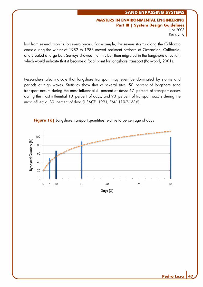
SAND BYPASSING SYSTEMS
MASTERS IN ENVIRONMENTAL ENGINEERING Part III | System Design Guidelines
June 2008 Revision 0
Pedro Loza 47
last from several months to several years. For example, the severe storms along the California coast during the winter of 1982 to 1983 moved sediment offshore at Oceanside, California, and created a large bar. Surveys showed that this bar then migrated in the longshore direction, which would indicate that it became a focal point for longshore transport (Boswood, 2001).
Researchers also indicate that longshore transport may even be dominated by storms and periods of high waves. Statistics show that at several sites, 50 percent of longshore sand transport occurs during the most influential 5 percent of days; 67 percent of transport occurs during the most influential 10 percent of days; and 90 percent of transport occurs during the most influential 30 percent of days (USACE 1991, EM-1110-2-1616).
Figure 16| Longshore transport quantities relative to percentage of days
0
20
40
60
80
100
0 5 10 30 50 75 100
Bypa
ssed
Qua
ntity
(%)
Days (%)

SAND BYPASSING SYSTEMS
MASTERS IN ENVIRONMENTAL ENGINEERING Part III | System Design Guidelines
June 2008 Revision 0
Pedro Loza 48
6. Site Characterization
Sand bypassing systems cannot be designed without careful consideration of the site where they will stand. Alongside with the abovementioned Coastal Processes Analysis, a broad study of the site’s characteristics is of vital importance for the success of the plant design.
In fact, a multidisciplinary team should compile a comprehensive Basis of Design Report to be presented to the designer that characterizes not only the costal processes but also:
− bathymetry and topography; − river and stream outflows; − evolution of the coastal system; − social factors; − environmental constrains.
The first of these points and their implications to the bypassing systems have been covered in the previous chapters. However, both the social and the environmental factors can influence greatly a number of aspects of the project.
Social Factors
Effects of a bypassing system on the local residents cannot be underestimated. Operation by-products like pollution, landscape changes, noise and others can set an entire town against the project and consequently lead to its downfall, as often occurs with all sorts of industrial facilities.
The best way to deal with these major factors is to involve the population on the pertinent aspects of the system, taking into account their concerns, habits and even alternatives. The social factors addressed in the Basis of Design Report should take the following questions as a starting point (USACE 1991, EM-1110-2-1616):
− Will recreational use of the beach limit bypassing during certain periods of the year? − Will the noise associated with the bypassing system exceed local standards? − Will air pollution from a diesel-powered plant create complaints? − Does the system block access to areas used for recreation?

SAND BYPASSING SYSTEMS
MASTERS IN ENVIRONMENTAL ENGINEERING Part III | System Design Guidelines
June 2008 Revision 0
Pedro Loza 49
− Does the plant fit in with the local style of architecture? − Will the pumping site conditions (e.g. jet pump crater) or discharge on the beach cause
recreational or safety problems? − Is there easy access to the electrical power at the site?
Nearby fishing communities or strong recreational traditions can be determining factors while considering the location of the bypassing plant’s elements, thus being decisive to the enduring success of the bypassing plant.
Figure 17| Jupiter Inlet, Florida
Sourc
e: h
ttp:/
/ww
w.e
vsju
piter
.com
/
In New South Whales, discussions related to the Tweed River Sand Bypassing System were held in the Regional Parliament, several years after the plant was operational. Issues on the table included the amount and rates of bypassed sand and its negative impact in surfing beaches downdrift of the discharge points (http://www.parliament.nsw.gov.au).
Another issue to bear in mind is the designated land-use of the different areas of the site. The presence of existing (or planned) structures may imply the relocation of part of the system to a different location, even though it may not be the best solution from a strictly technical point of view.
SAND BYPASSING SYSTEMS
MASTERS IN ENVIRONMENTAL ENGINEERING Part III | System Design Guidelines
June 2008 Revision 0
Pedro Loza 50
Building a SBS often leads to a sense of safety and stability regarding the coastline, which increases development pressures in the nourished areas. As explored before, one of the false premises affecting the management of coastal areas is the perception that the human scale and timeframe are compatible with the erosion and accretion processes on the shores. What must be clearly presented to the decision makers is that, upon the implementation of a sand bypassing system, all mean required to keep it operating must be provided. Otherwise, all the coastal processes will return.
Thus, if a bypassing system is built to avoid the loss of property or revenues from tourism or improve storm protection, it must be noted that, once its operation is interrupted, the same problems will return.
Environmental Constrains
Due to its very nature, any sand bypassing plant has a significant impact on the environment, and although it is designed to improve sediment transport conditions, negative consequences can arise from its operation.
In most countries, an Environmental Impact Assessment (EIA) study is mandatory prior to the final approval of the system’s design. Although the specific scope of the EIA varies from plant to plant and the procedures vary according to the legislation of each country, the following points are usually analyzed in the final report:
− Environmental data collection; − Alternative locations and types of system; − Environmental Impact Matrices and Maps; − Recommendations.
Common environmental constrains identified include nearby nesting areas for certain species of birds (ex. Case 4 – Oceanside Harbour), affected beaches located in protected areas (ex. Case 5 - Indian River Inlet) or the presence of heavy metals in the sediments (ex. Case 8 – East Pass).

SAND BYPASSING SYSTEMS
MASTERS IN ENVIRONMENTAL ENGINEERING Part III | System Design Guidelines
June 2008 Revision 0
Pedro Loza 51
Additional negative environmental impacts include a short-term increase in the turbidity of the nearshore areas from the dewatering of the slurry leading to a reduction of the photosynthesis activity. The nourishment operations bury invertebrate fauna which may conduct to a decay in the populations of migratory, nesting and overwintering shorebirds that feed on intertidal invertebrates. (2008, Florida Fish and Wildlife Research Institute)
While considering the construction of a bypassing system, the decision makers must take into account not only the negative but also the positive impacts of the project. Often, an eroded beach removes the habitat for sandy beach creatures and so renourishment can often be a positive contribution. In Florida there was concern that the dredge pipes would suck turtles into the pumps. A special vacuum cleaner grill was designed and added to the dredge pipes that ensured that turtles were not sucked in with the sand. (2008, Wikipedia: Beach Nourishment).
More specifically, comprehensive Environmental Management Plans (EMP) should be developed for sand bypassing project to address issues raised in the environmental impact assessment. Specific management plans should focus on the construction of the permanent system, including any dredging or nourishment activity.
The Construction EMP should include: consultation, disruptions to public access, community information, noise and vibration management, traffic and air quality management, soil and water quality management, cultural heritage management, infrastructure management, waste management, sand removal and placement strategy, sand and water quality management, bird habitat, landscaping management and accident and emergency responses.
A specific EMP addressing the issues raised in the environmental impact assessment that relate to the long term operation of the system should also be developed. The Operation EMP should address the same issues focused in the Construction EMP, as well as surf quality, nourishment strategy and beach monitoring and management.

SAND BYPASSING SYSTEMS
MASTERS IN ENVIRONMENTAL ENGINEERING Part III | System Design Guidelines
June 2008 Revision 0
Pedro Loza 52
7. Design Guidelines & Conclusions Throughout the previous chapters, each element of the sand bypassing systems was presented individually, in an effort to organize all gathered data in a systematic way. In this chapter, final conclusions and recommendations are presented as general guidelines for design.
As presented in Chapter 4, an incomplete or inaccurate knowledge of the sediment transport system is the most common cause of bypassing failure. Thus, a thorough data collection stage must be the starting point for the design team. The data collection report should include:
− Topography and bathymetry of the surrounding area; − Wind, current and wave data; − Aerial photographs or charts, depicting the evolution of the sediment system.
Once all data is collected and compiled, the coastal processes study should begin. Using bathymetry and climatological data, a wave transformation model must be developed. This wave transformation study is intended to transfer offshore waves to the shallow areas around the project site. The wave model outputs will then be used to define the design wave heights and wave set-ups for the different sections of the project as well as the annual wave climate necessary to assess sediment transport.
This set of data should then be merged with all sedimentological information, as described in Chapter 5. The analysis of the mentioned data should conclude on how the existing sediment transport occurs and should provide the following:
− Sources and pathways of sediments; − Gross and net transport rates; − Coastline evolution and trends.
Based on the characterization of the existing situation and on the studies carried out, the coastal processes report should include the main design criteria for the sand bypassing plant, namely bypassing quantities, wave climate, sediment characteristics and others.

SAND BYPASSING SYSTEMS
MASTERS IN ENVIRONMENTAL ENGINEERING Part III | System Design Guidelines
June 2008 Revision 0
Pedro Loza 53
While the coastal processes study is underway, data for the Environmental Impact Assessment (EIA) study should be collected and evaluated. Social factors and environmental constrains that might matter to the location of any sand bypassing element or otherwise influence its design should be noted and mitigated during the initial stages of plant design. Other data concerning the site and the surrounding area, such as existing structures or planned land-uses should also be gathered at this stage so that it can be taken into account when designing the bypassing system.
At the outset of the design stage, the first points of focus involve choosing the type of bypassing system and operation mode. As mentioned in Chapter 2, mobile systems (land- or water-based) are usually more flexible and can better adapt to medium or long-term changes in the site conditions. Although they usually have smaller nominal transport capacities than fixed systems, they are not subject to clogging or other disadvantages and can therefore carry similar sand volumes per year.
Fixed bypassing systems are often presented as a complete, permanent solution to sediment transport problems. However, in order to ensure a successful design of such a plant, the site conditions must be known in great detail, as any misjudgement may render the plant ineffective, or even useless.
While defining the general characteristics of the system, it is always important to relate specifically to the site where the plant is going to be located. Because the discharge point is essentially independent of the bypassing system or method it can be one of the first elements to define. As referred in Chapter 2, the designer should determine the location where the nearshore bottom contours become parallel to the shoreline. Whenever possible, the sediments should be discharged within the surf zone, so that wave action can carry the sand, shaping the downdrift beaches.
As one can see from the previous chapters, selecting the borrow area is far more difficult as many variables must be taken into consideration and given that many relevant factors are specific to each site. Because mobile systems are more flexible, usually a broader area or even several areas can be defined as a sediment source. Fixed, interception-mode systems require a high degree of certainty as to the rates and direction of littoral drift. The design of these systems

SAND BYPASSING SYSTEMS
MASTERS IN ENVIRONMENTAL ENGINEERING Part III | System Design Guidelines
June 2008 Revision 0
Pedro Loza 54
often includes sand traps in the design of the borrow areas as an effective way to maximize the bypassing capacity of the system.
Once the concept design of the system is finished, the project needs to be validated within the scope of an EIA, where all the short and long-term impacts of the system and mitigation actions are presented. A critical part of the EIA is the development of the Environmental Management Plans which expose the methodology related to construction and operation of the bypassing system.
The outcome of these tasks – Data Collection, Coastal Processes Study and Environmental Impact Assessment – include the definition of the bypassing plant’s characteristics up and its general concepts up to a schematic design stage. However, the detailed design of the system’s components is set on a wide array of patented equipment. For this reason, it is common for these systems to be awarded to contractors after a Design and Build tender – and in many cases, such as Tweed River Inlet, even the operation of the plant for a period of several years is awarded to the contractor.
In this case, the design team should develop the project to include all the necessary elements for the contractors to present their proposals. Then, all bids must be analyzed and compared bearing in mind all the collected data and design parameters.

SAND BYPASSING SYSTEMS
MASTERS IN ENVIRONMENTAL ENGINEERING Part III | System Design Guidelines
June 2008 Revision 0
Pedro Loza 55
8. References
1. (2004), Mackay Coastal Study, Queensland Government – Environmental Protection Agency
2. Dean, R., Davis, A. and Erikson, K. (2003), Beach Nourishment with Emphasis on Geological Characteristics Affecting Project Performance, NOAA Coastal Services Center
3. Pound, M. (2002), Fifteen years operations of the Gold coast Seaway Sand Bypassing System, 30th PIANCAIPCN Congress, Australia
4. Pound, M. (2002), The use of Fixed Sand Bypassing Systems at Tidal Entrances, Coast to Coast Conference 2002
5. (Apr 2002), Coastal Engineering Manual, EM 1110-2-1100, US Army Corps of Engineers
6. Dalrymple, R. (2002), Coastal Specific Hazards, Center for Applied Coastal Research University of Delaware
7. (2002), Technical Standards and Commentaries for Port and Harbour Facilities in Japan
8. Boswood, P., Murray, R. (2001), World-wide Sand Bypassing Systems: Data Report (Compiled 1997), Queensland Government – Environmental Protection Agency
9. Clausner, J. (Dec 1999), Sand Bypassing Cost and Performance Database, CETN-II-41, US Army Corps of Engineers
10. (Mar 1998), Conduits, Culverts, And Pipes, EM 1110-2-2902, US Army Corps of Engineers
11. Hales, Z. (Nov 1995), Dredge Plant Equipment And Systems Processes, DRP-95-10, US Army Corps of Engineers
12. (Jun 1995), Design Of Coastal Revetments, Seawalls, And Bulkheads, EM 1110-2-1614, US Army Corps of Engineers
13. Williams, G., Clausner, J. (Jan 1995), Field Test of the Dredging Research Program

SAND BYPASSING SYSTEMS
MASTERS IN ENVIRONMENTAL ENGINEERING Part III | System Design Guidelines
June 2008 Revision 0
Pedro Loza 56
(DRP) Eductor, DRP-3-12, US Army Corps of Engineers
14. Walls, B., Lemlich, S. et al (Oct 1994), Open-Water Placement of Dredged Sediments: A Framework for Site Management, DRP-5-10, US Army Corps of Engineers
15. Clausner, J. (Dec 1992), Fluidizer System Design for Channel Maintenance and Sand Bypassing, DRP-3-09, US Army Corps of Engineers
16. (Nov 1992), Palermo, M., Francingues, N. et al, Evaluating Environmental Effects of Dredged Material Management Alternatives, Environmental Protection Agency and US Army Corps of Engineers
17. (Aug 1992), Coastal Littoral Transport, EM 1110-2-1502, US Army Corps of Engineers
18. (Mar 1991), Tidal Hydraulics, EM 1110-2-1607, US Army Corps of Engineers
19. (Jan 1991), Sand Bypassing System Selection, EM 1110-2-1616, US Army Corps of Engineers
20. Clausner, J. (Sep 1990), Jet Pump Sand Bypassing – An Update, DRP-3-03, US Army Corps of Engineers
21. Clausner, J. (Dec 1989), Jet Pump Sand Bypassing – Nerang River Entrance, Australia, DRP-3-01, US Army Corps of Engineers
22. (Jul 1989), Environmental Engineering For Coastal Shore Protection, EM 1110-2-1204, US Army Corps of Engineers
23. (Jun 1987), Beneficial Uses of Dredged Material, EM 1110-2-5026, US Army Corps of Engineers
24. (Jun 1987), Beneficial Uses of Dredged Material, EM 1110-2-5026, US Army Corps of Engineers
Internet

SAND BYPASSING SYSTEMS
MASTERS IN ENVIRONMENTAL ENGINEERING Part III | System Design Guidelines
June 2008 Revision 0
Pedro Loza 57
1. (2008), Beach Nourishment, Wikipedia
http://en.wikipedia.org/wiki/Beach_nourishment
2. (2008), Save Our Beach, Smith, D.
http://saveourbeach.wordpress.com/2008/01/23/contempt-of-court-by-pondicherry-government/
3. (2008), Fish and Wildlife Research Institute, Florida Fish and Wildlife Research Institute
http://research.myfwc.com/features/view_article.asp?id=28829
4. (2007), Tweed River Entrance Sand Bypass Project, Queensland Government– Environmental Protection Agency
http://www.tweedsandbypass.nsw.gov.au/index.html
5. (2007), Beach Nourishment: A Guide for Local Government Officials, National Oceanic and Atmospheric Administration – Coastal Services Center
http://www.csc.noaa.gov/beachnourishment/html/human/socio/taxbase.htm
6. (2006), Tweed River Entrance Sand Bypass Project, Parliament of New South Whales
http://www.parliament.nsw.gov.au/prod/parlment/hansart.nsf/5f584b237987507aca256d09008051f3/390276790f43d030ca25723600075350!OpenDocument

PEDRO LOZA
JUNE 2008
SAND BYPASSING SYSTEMS ANNEXES – DETAILED WORLDWIDE DATA

PEDRO LOZA 1
Index
Case 1 – Nerang River Entrance ................................. 2
Case 2 – Tweed River Entrance .................................. 4
Case 3 – South Lake Worth Inlet ................................. 7
Case 4 – Oceanside Harbour ..................................... 9
Case 5 – Indian River Inlet ....................................... 12
Case 6 – Lake Worth Inlet ........................................ 15
Case 7 – Carolina Beach Inlet .................................. 18
Case 8 – East Pass .................................................. 21
Case 9 – Hillsboro Inlet ........................................... 23
Case 10 – Jupiter Inlet ............................................. 25
Case 11 – Little River Inlet ........................................ 27
Case P7 – Mexico Beach Inlet .................................. 29
Case 12 – Masonboro Inlet ...................................... 31
Case 13 – Ponce de Leon Inlet ................................. 34
Case 14 – Santa Barbara ........................................ 36
Case 14 – Sebastian Inlet ........................................ 38
Case 15 – Rudee Inlet ............................................. 40
Case 16 – Santa Cruz ............................................. 43
Case 17 – Ventura Marina ...................................... 45
Case 18 – Port Sanilac ............................................ 47
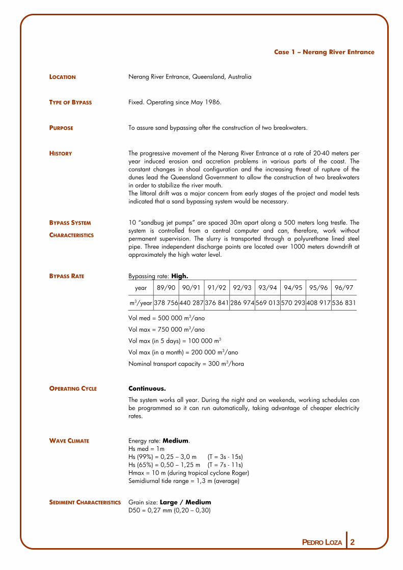
PEDRO LOZA 2
Case 1 – Nerang River Entrance
LOCATION Nerang River Entrance, Queensland, Australia
TYPE OF BYPASS Fixed. Operating since May 1986.
PURPOSE To assure sand bypassing after the construction of two breakwaters.
HISTORY The progressive movement of the Nerang River Entrance at a rate of 20-40 meters per year induced erosion and accretion problems in various parts of the coast. The constant changes in shoal configuration and the increasing threat of rupture of the dunes lead the Queensland Government to allow the construction of two breakwaters in order to stabilize the river mouth. The littoral drift was a major concern from early stages of the project and model tests indicated that a sand bypassing system would be necessary.
BYPASS SYSTEM
CHARACTERISTICS
10 “sandbug jet pumps” are spaced 30m apart along a 500 meters long trestle. The system is controlled from a central computer and can, therefore, work without permanent supervision. The slurry is transported through a polyurethane lined steel pipe. Three independent discharge points are located over 1000 meters downdrift at approximately the high water level.
BYPASS RATE Bypassing rate: High.
year 89/90 90/91 91/92 92/93 93/94 94/95 95/96 96/97
m3/year 378 756 440 287 376 841 286 974 569 013 570 293 408 917 536 831
Vol med = 500 000 m3/ano
Vol max = 750 000 m3/ano
Vol max (in 5 days) = 100 000 m3
Vol max (in a month) = 200 000 m3/ano
Nominal transport capacity = 300 m3/hora
OPERATING CYCLE Continuous.
The system works all year. During the night and on weekends, working schedules can be programmed so it can run automatically, taking advantage of cheaper electricity rates.
WAVE CLIMATE Energy rate: Medium. Hs med = 1m Hs (99%) = 0,25 – 3,0 m (T = 3s - 15s) Hs (65%) = 0,50 – 1,25 m (T = 7s - 11s) Hmax = 10 m (during tropical cyclone Roger) Semidiurnal tide range = 1,3 m (average)
SEDIMENT CHARACTERISTICS Grain size: Large / Medium D50 = 0,27 mm (0,20 – 0,30)

PEDRO LOZA 3
COSTS
(APPROXIMATE VALUES IN �) Year 89/90 90/91 91/92 92/93 93/94 94/95 95/96 96/97
�/year 386 000 345 600 446 600 516 800 602 900 686 445 671 432 735 289
� / m3 1.02 0.78 1.18 1.95 1.06 1.20 1.64 1.30
CONTRACT TYPE Design – Construction Contract signed to McConnell-Dowell. Operations and maintenance conducted by the Environmental Protection Agency.
OPERATING CONSTRAINTS No environmental constraints.
INLET AND BEACH USAGE Recreational boating, fishing and commercial vessels use the river channel. Neighbouring beaches are undeveloped and have no users.
BYPASSING SCHEME
REFERENCES
DATA ACCURACY High.
OTHER DATA The pier is open to fishermen and the general public, subject to a fee.
NOTES

PEDRO LOZA 4
Case 2 – Tweed River Entrance
Location Tweed River Entrance, Queensland, Australia
Type of Bypass Fixed. Operating since March 2001.
Purpose To ensure sand bypassing at the river mouth and improve conditions for users of
neighbouring beaches.
History After several dredging operations and the construction of two breakwaters the erosion
and accretion patterns around the river mouth changed, inducing the formation of
shoals. To ensure the maintenance of the navigation channel, a project was developed
consisting of two phases:
- a series of dredging operations allowed the reestablishment of the beach
profiles where needed;
- the construction of a fixed bypassing system.
Bypass System
Characteristics
11 jet pumps stand along a pier, built for that purpose (up to 5 pumps can work
simultaneously). The system is controlled from a central computer and can, therefore,
work without permanent supervision. The slurry is transported through polyurethane
lined steel pipe over a distance that exceeds 2000 meters. Four independent discharge
points are located over 1000 meters downdrift at approximately the high water level.
In order to achieve instant results, the construction of the bypassing system was
preceded by a dredging operation. Ever since that time, the system has operated
under a continuous environmental monitoring program which includes video
surveillance.
Bypass Rate Bypassing rate: High.
year 2000 2001 2002 2003 2004 2005 2006
m3/year 406 300 416 200 240 100 230 900 170 000 51 600 200 300
Vol med = 245 000 m3/yr
Vol max = 780 000 m3/yr
Nominal transport capacity = 500 m3/hr
Operating Cycle Continuous.

PEDRO LOZA 5
The system works all year. Beach discharges occur mainly during the night in order to
minimize impact on users. During the night and on weekends, working schedules can
be programmed so it can run automatically, taking advantage of cheaper electricity
rates.
Wave Climate Energy rate: Medium. Hs med = 1,3 m Hs (90%) = 0,6 – 2,4 m (T = 5s - 13s) Hmax = 13,1 m (3.5.1996) Semidiurnal tide range = 1,3 m (average)
Sediment Characteristics Grain size: Large / Medium D50 = 0,27 mm (0,20 – 0,30)
Costs
(approximate values in �)
N/A
Contract Type Design – Construction Contract signed to McConnell-Dowell. Operations and maintenance conducted by the Environmental Protection Agency.
Operating constraints Even tough no negative impacts were expected, a thorough environmental monitoring
program was developed. It includes several areas: beach evolution, wave and swell
conditions, river tides, local fauna and flora.
Inlet Usage The river entrance is used as a navigation channel.
Neighbouring beaches have recreational use.
Bypassing Scheme
References

PEDRO LOZA 6
Data Accuracy High.
Other Data
Notes

PEDRO LOZA 7
Case 3 – South Lake Worth Inlet
Location South Lake Worth Inlet, Florida, EUA
Type of Bypass Fixed. Operating since 1937 (with different configurations).
Purpose To ensure navigability in the lake’s access channel and reduce erosion in downdrift
beaches.
History South Lake Worth Inlet is an artificial entrance connecting the lake to the ocean and
was first constructed in 1927 to allow tidal circulation, improving the water quality of
the lake. The construction of the training walls fixed the inlet but halted the net
transport, inducing erosion on the downdrift beaches and the shoaling of the entrance
channel. The erosion threatened upland structures and a major highway.
A first pumping station was built in 1937 and placed sand 350 m downdrift.
In 1948 the intake was suspended from a semi-mobile structure, allowing sand to be
collected from a 10 m radius, therefore increasing the plant’s capacity.
The system got its present configuration in 1967 with the extension of the breakwaters
and the relocation of the plant, closer to the sea and a consequent increase in
transport capacity.
Bypass System
Characteristics
Sediment intake is achieved through a fixed hydraulic suction dredge with a rotating
boom. The plant can create a circular trench with about 800 m3 (300 m2 by 2,5-3,0 m
deep).
The transport pipeline crosses the inlet suspended from the highway bridge and
discharges sand 350 m downdrift from the pumping station.
Bypass Rate Bypassing rate: Medium.
Vol med = 53 500 m3/yr
Nominal transport capacity = 110 m3/hr
Operating Cycle Continuous.
The system can operate all year round, with only two workers. Weather conditions
limit the bypassing periods. Small system capacity is mainly justified by slow filling of
the crater – only on 20% of the operations is the crater filled faster than dredged. In its
original conception, the crane was mounted on rails and was for greater trap capacity.
Wave Climate Energy rate: High. (subject to tropical storms and cyclones).

PEDRO LOZA 8
Sediment Characteristics Grain size: Large D50 = 0,30 mm (0,29 – 0,32)
Costs
(approximate values in �)
Bypassing cost is at about � 8 / m3.
Contract Type N/A
Operating constraints Neighbouring beaches have heavy use.
Inlet Usage The river entrance is used as a navigation channel by small commercial and
recreational craft. Neighbouring beaches have recreational use.
Bypassing Scheme
References
Data Accuracy High.
Other Data
Notes

PEDRO LOZA 9
Case 4 – Oceanside Harbour
(Experimental System)
Location Oceanside Harbour, California, EUA
Type of Bypass Fixed. Operating from June 1989 to November 1996.
Purpose To ensure sand transport and improve channel navigability in the harbour entrance.
History The construction of the harbour complex interrupted the littoral drift, with usual
consequences: accretion along the northern breakwater, erosion in the downdrift
beaches and formation of shoals in the harbour entrance.
Bypass System
Characteristics
Phase 1 (Jun 1989 – Aug 1990): A single jet pump operates by the northern
breakwater (250 m3/hr), on a crane and a fluidiser. Two other jet pumps are
supported on a barge located on the navigation channel (175 m3/hr). Sediment is
transported across 3300 m, impelled by a pumping plant located on land.
Phase 2 (Nov 1991 – Nov 1996): Addition of a 50 m fluidiser oriented
shoreward parallel to the south breakwater. A valve was introduced in the system to
supply firstly the fluidiser and then the jet pumps, because the pumping plant couldn’t
support both simultaneously.
Phase 3 (Cancelled for lack in funding): Would include another set of fluidisers
by the southern breakwater, an increase in jet pump capacity and the construction of
separate pumps to power the fluidisers.
Bypass Rate Bypassing rate: Medium / Low.
Phase 1
Vol med = 14 000 m3/yr
Vol med = 48 m3/hr (744 hours of bypassing)
Nominal transport capacity = 425 m3/hr
Phase 2
Vol med = 80 000 m3/yr
Vol med = 73 m3/hora
Nominal transport capacity = 425 m3/hr
Operating Cycle Continuous.
The system was designed to operate 5 days a week, for up to 10 hours a day.
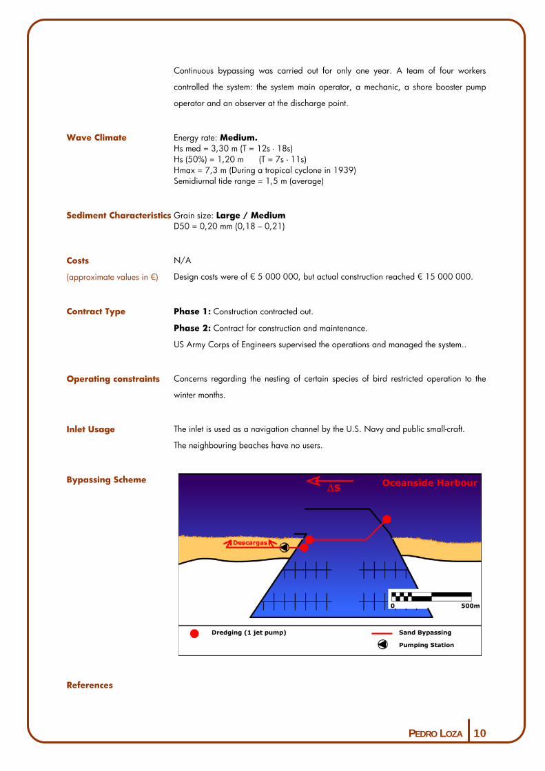
PEDRO LOZA 10
Continuous bypassing was carried out for only one year. A team of four workers
controlled the system: the system main operator, a mechanic, a shore booster pump
operator and an observer at the discharge point.
Wave Climate Energy rate: Medium. Hs med = 3,30 m (T = 12s - 18s) Hs (50%) = 1,20 m (T = 7s - 11s) Hmax = 7,3 m (During a tropical cyclone in 1939) Semidiurnal tide range = 1,5 m (average)
Sediment Characteristics Grain size: Large / Medium D50 = 0,20 mm (0,18 – 0,21)
Costs
(approximate values in �)
N/A
Design costs were of � 5 000 000, but actual construction reached � 15 000 000.
Contract Type Phase 1: Construction contracted out.
Phase 2: Contract for construction and maintenance.
US Army Corps of Engineers supervised the operations and managed the system..
Operating constraints Concerns regarding the nesting of certain species of bird restricted operation to the
winter months.
Inlet Usage The inlet is used as a navigation channel by the U.S. Navy and public small-craft.
The neighbouring beaches have no users.
Bypassing Scheme
References

PEDRO LOZA 11
Data Accuracy High.
Other Data Severe storms along the California coast during the winter of 1982 to 1983 moved
sediment offshore at Oceanside, and created a large bar. Surveys showed that this bar
then migrated in the longshore direction, which would indicate that it became a focal
point for longshore transport. This data was used while designing the bypassing
system.
Notes Major problems were associated with clogging and plugging of the fluidisers with
sand which reduced the amount of sand being pumped by the jets. Because the
equipment was designed to operate at two sites, it performed poorly at both.
The system had to be maintained by divers under difficult conditions due to long period
swell which produced a surge in the entrance.
The system was located in the inlet, adjacent to the navigation channel, providing
some constrictions to navigation.
Funding was often late and insufficient and the booster station had high costs.

PEDRO LOZA 12
Case 5 – Indian River Inlet
Location Indian River Inlet, Delaware, EUA
Type of Bypass Mobile. Operating since January 1990.
Purpose To prevent erosion associated with the construction of two training walls necessary to
stabilise the river inlet.
History The training walls were constructed to stabilise the navigation channel which was
prone to migrating within a 3500 metres region as well as occasionally closing. These
structures have been associated with the progressive erosion of the downdrift beach,
threatening a major highway which runs parallel to the coast.
Bypass System
Characteristics
A single jet pump is mounted on a crawler crane and can create craters with 15 m in
diameter and 5,5 m deep. The system can create a trench of three craters diameters
length before repositioning. Sediment capture is powered by a specific pumping group
(400hp). A discharge booster pump (400 – 600 hp) is used to carry the slurry across a
650 m HPDE pipeline. The pipeline crosses the inlet anchored to a bridge.
Bypass Rate Bypassing rate: Medium.
Year 1990 1991 1992 1993 1994 1995
m3/yr 86 000 63 000 51 700 51 800 64 660 52 560
Vol med = 60 000 m3/ano
Vol max = 86 000 m3/ano
Vol med in 1 day = 1 300 m3/day
Nominal transport capacity = 250 m3/hr
Operating Cycle Continuous.
The system is prepared to work on a daily basis, but bypassing operations only take
place during 40% of available time, due to sand capture. Because of intense beach
use, bypassing is generally interrupted for the summer (three months a year).
Wave Climate Energy rate: High. (subject to tropical storms and cyclones). Hs med = 1,3 m Hs (90%) = 0,6 – 2,4 m (T = 5s - 13s) Hmax = 13,1 m (1996)
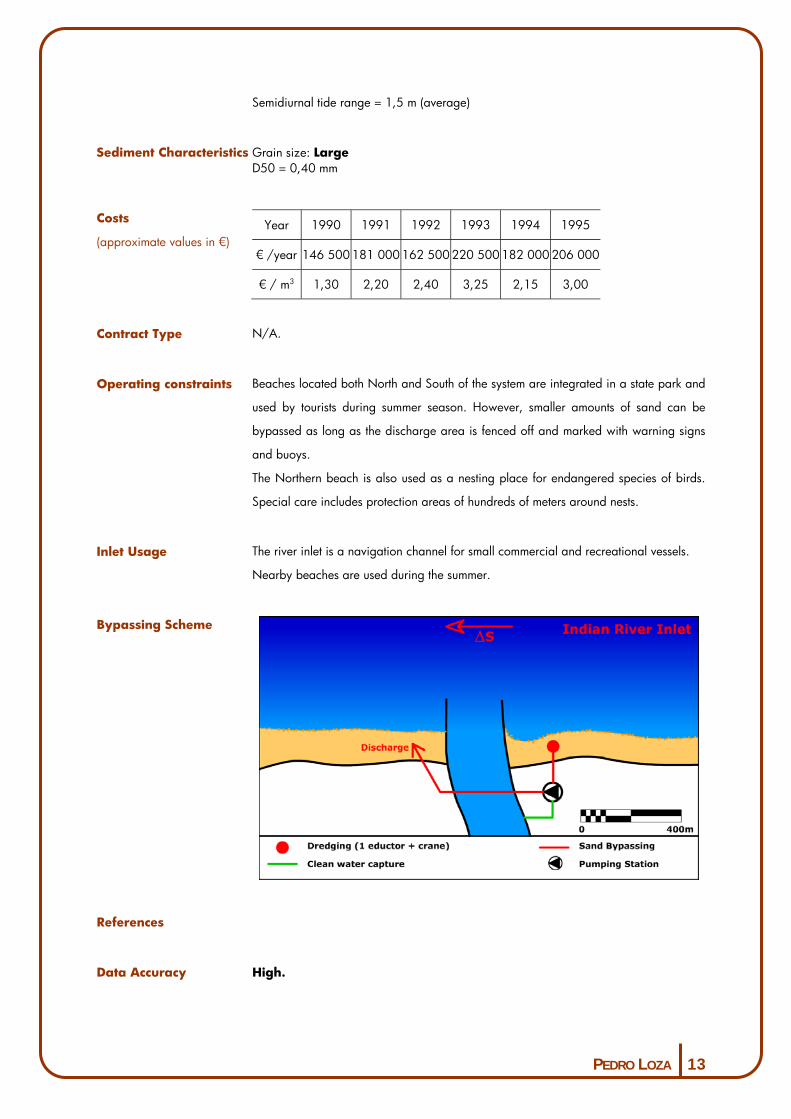
PEDRO LOZA 13
Semidiurnal tide range = 1,5 m (average)
Sediment Characteristics Grain size: Large D50 = 0,40 mm
Costs
(approximate values in �) Year 1990 1991 1992 1993 1994 1995
� /year 146 500 181 000 162 500 220 500 182 000 206 000
� / m3 1,30 2,20 2,40 3,25 2,15 3,00
Contract Type N/A.
Operating constraints Beaches located both North and South of the system are integrated in a state park and
used by tourists during summer season. However, smaller amounts of sand can be
bypassed as long as the discharge area is fenced off and marked with warning signs
and buoys.
The Northern beach is also used as a nesting place for endangered species of birds.
Special care includes protection areas of hundreds of meters around nests.
Inlet Usage The river inlet is a navigation channel for small commercial and recreational vessels.
Nearby beaches are used during the summer.
Bypassing Scheme
References
Data Accuracy High.

PEDRO LOZA 14
Other Data
Notes
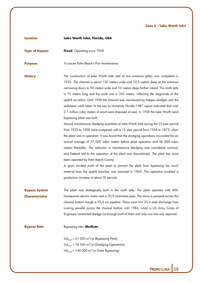
PEDRO LOZA 15
Case 6 – Lake Worth Inlet
Location Lake Worth Inlet, Florida, USA
Type of Bypass Fixed. Operating since 1958.
Purpose To assure Palm Beach’s Port maintenance.
History The construction of Lake Worth Inlet and its two entrance jetties was completed in
1925. The channel is about 120 meters wide and 10,5 meters deep at the entrance
narrowing down to 90 meters wide and 10 meters deep farther inland. The north jetty
is 75 meters long and the south one is 335 meters, reflecting the magnitude of the
updrift accretion. Until 1958 the channel was maintained by hopper dredges and the
sediments were taken to the sea (a University Florida 1987 report indicated that over
2.1 million cubic meters of sand were disposed at sea). In 1958 the Lake Worth sand
bypassing plant was built.
Annual maintenance dredging quantities at Lake Worth Inlet during the 23-year period
from 1935 to 1958 were compared with a 15 year period from 1958 to 1873, when
the plant was in operation. It was found that the dredging operations accounted for an
annual average of 37 000 cubic meters before plant operation and 36 000 cubic
meters thereafter. The reduction in maintenance dredging was considered nominal,
and Federal aid to the operation of the plant was discontinued. The plant has since
been operated by Palm Beach County.
A groin located north of the plant to prevent the plant from bypassing too much
material from the updrift beaches was removed in 1969. This operation enabled a
production increase of about 30 percent.
Bypass System
Characteristics
The plant was strategically built in the north jetty. The plant operates with 400-
horsepower electric motor and a 30,5 centimetre pipe. The slurry is pumped across the
channel bottom trough a 25,4 cm pipeline. There were two 25,4 steel discharge lines
running parallel across the channel bottom until 1984, when a US Army Corps of
Engineers contracted dredge cut through both of them and only one line was repaired.
Bypass Rate Bypassing rate: Medium.
Volmed = 61 000 m3/yr (Bypassing Plant)
Volmed = 76 500 m3/yr (Dredging Operations)
Volmed = 140 000 m3/yr (Total Bypassing)
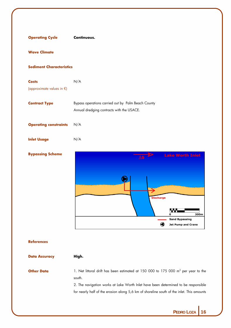
PEDRO LOZA 16
Operating Cycle Continuous.
Wave Climate
Sediment Characteristics
Costs
(approximate values in �)
N/A
Contract Type Bypass operations carried out by Palm Beach County
Annual dredging contracts with the USACE.
Operating constraints N/A
Inlet Usage N/A
Bypassing Scheme
References
Data Accuracy High.
Other Data 1. Net littoral drift has been estimated at 150 000 to 175 000 m3 per year to the
south.
2. The navigation works at Lake Worth Inlet have been determined to be responsible
for nearly half of the erosion along 5,6 km of shoreline south of the inlet. This amounts

PEDRO LOZA 17
to a loss of 51 000 m3 annually (based on surveys over the 24-year period from 1955
to 1979). For the beaches beyond the 5,6 km south of the inlet, there is no evidence
that the navigation project has significantly affected the shore processes.
Notes

PEDRO LOZA 18
Case 7 – Carolina Beach Inlet
Location Carolina Beach Inlet, North Carolina, USA
Type of Bypass Mobile. Operating since 1965.
Purpose Prevent further beach erosion due to severe hurricanes and the artificial opening of the
inlet.
History Carolina Beach began to experience problems along its shoreline in the early 1950’s
due to the passage of severe hurricanes over the area and more importantly as a direct
result of the artificial opening of the Carolina beach Inlet in 1952. Sand trapped in the
ebb- and flood- tidal deltas of the inlet has caused severe beach erosion south of the
inlet. The hurricane and shore protection project for the shoreline fronting the town of
Carolina Beach was authorized in 1962 and those beaches have been nourished
several times since 1965.
Bypass System
Characteristics
The nourishment project is based a floating dredge working in an inlet sand trap at
Carolina Beach Inlet.
Three relatively small traps, of about 76 500 m3 each were dredged in the throat of
the inlet in 1967, 1968 and in 1970, respectively, to determine the impact of such a
trap on the ebb- tide channel and delta but these studies were inconclusive. The last
report recommended dredging a 370 000 m3 trap in the inlet throat to provide sand to
nourish the beaches. When an emergency beach fill was needed in 1981, it was
decided to dredge a 306 000 m3 trap in the suggested location. By 1984, three years
after the dredging operations, it had accumulated 206 000 m3, producing an average
accumulation rate of 69 000 m3 per year.
Overall, the trap functioned well, but the inner portions of the trap were close to the
landward inlet throat, subjected to the high ebb and flood velocities. Consequently, the
rate of accumulation in these sections was relatively low. The Carolina Beach Project
was completed in July 1982, with the placement of over 27 million m3 of sand along
the project. This material was dredged from upland areas along the Cape Fear River,
which flows west of the town of Carolina Beach. During the 1985 nourishment
operations, the trap was repositioned seaward to increase its trapping ability. Recent
surveys over the inlet and sediment trap area indicate that it will provide a sufficient
amount of material for future nourishment operations.
Channel maintenance at Carolina Beach Inlet is accomplished by either a sidecaster
dredge or a split-hull hopper dredge. When this last one is used, material is released

PEDRO LOZA 19
just south of the inlet as close to the shore as possible (about 3 m of water). It is
believed that this form of hopper dredge bypass is beneficial to the project. The
disposed mounds of material erode away with littoral drift, thereby supplying material
to the downcoast beaches.
Bypass Rate Bypassing rate: Medium.
Vol med = 122 000 m3/ano (estimated)
Operating Cycle Varies according with the needs.
Bypass projects are expected to take place every 3 years.
Wave Climate
Sediment Characteristics
Costs
(approximate values in �)
Contract Type N/A
Operating constraints N/A
Inlet Usage N/A
Bypassing Scheme

PEDRO LOZA 20
References
Data Accuracy High.
Other Data Actual bypassing quantities during each operation are determined from beach profile
surveys. The original estimate of a bypassing rate of 122 000 m3 per year was based
on a detail sediment budget analysis of measured erosion losses from Carolina Beach.
Actual losses measure between 1982 and 1985 indicate an average rate of
150 000 m3 per year.
Notes

PEDRO LOZA 21
Case 8 – East Pass
Location East Pass, Florida, USA
Type of Bypass Mobile. Operating since 1930.
Purpose Maintenance of entrance channel navigability.
History The inlet was formed by a storm surge in 1923. In 1930, Congress authorized a
Federal Project to provide a 1.8 m deep by 30.5 m wide channel through the inlet. By
the time navigation works where completed in 1969, a 1 m deep by 50 m wide
channel was authorized. The west jetty is 1 500 m long, and the east jetty is 700 long.
Bypass System
Characteristics
Dredging operations were carried out at 6-months intervals to maintain project depths
between 1970 and the 1980’s. In time, a section of the inlet channel (between the
jetties and the US route 98 bridge) migrated east. Since natural scour through this
section of the channel maintained sufficient depth, dredging was abandoned there.
The west jetty was originally constructed with a weir section, prior to the dredging of a
deposition basin on the west side of the channel. Dredging was continued in the
lagoon channel (north of US 98) and the outer bar (ebb-shoal) channel on an annual
and sometimes twice yearly basis. By the 1980’s, it was decided to that maintenance
dredging would reach 2.4 m below project depth on the bar channel and 1.8 m on
the lagoon channel.
This approach proved to be efficient for a few years until the weir was closed in 1986.
Shoreline erosion along the beaches inside the inlet has become a problem since the
closure of the weir and nearby development was threatened. Because a deep hole and
trench were scoured out near the east jetty, undermining of the structure became a
concern. A May-June 1987 dredging operation realigned the migrating portion of the
channel to a central location, and the dredged sand was used to fill the scoured areas
near the east jetty and to nourish the eroding shoreline along this area.
Bypass Rate Bypassing rate: N/A
Vol med = N/A
Operating Cycle Dredging operations were carried out bi-annualy to maintain project depths.
Wave Climate N/A

PEDRO LOZA 22
Sediment Characteristics N/A
Costs
(approximate values in �)
N/A
Contract Type N/A
Operating constraints N/A
Inlet Usage N/A
Bypassing Scheme
References
Data Accuracy Medium.
Other Data The eastern shoreline advanced along the east jetty over 2 000 feet during a 10-year
period following construction. Predictions preceding the project referred that littoral
direction dominance was complicated by a significant seasonal drift reversal. Channel
shoaling at East Pass has been attributed to the natural bypassing of material around
the east jetty. A very large ebb-tidal shoal has also formed seaward of the jetties. The
incorrectly placed weir was closed in 1986.
Notes
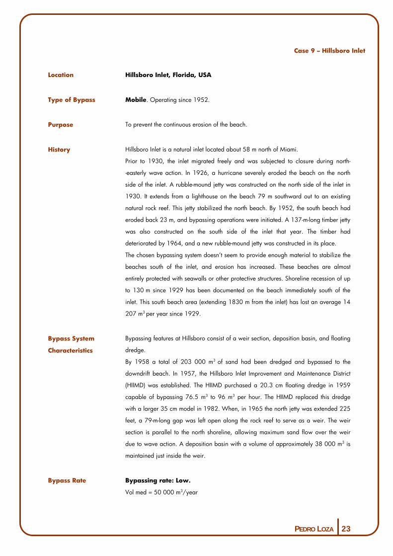
PEDRO LOZA 23
Case 9 – Hillsboro Inlet
Location Hillsboro Inlet, Florida, USA
Type of Bypass Mobile. Operating since 1952.
Purpose To prevent the continuous erosion of the beach.
History Hillsboro Inlet is a natural inlet located about 58 m north of Miami.
Prior to 1930, the inlet migrated freely and was subjected to closure during north-
-easterly wave action. In 1926, a hurricane severely eroded the beach on the north
side of the inlet. A rubble-mound jetty was constructed on the north side of the inlet in
1930. It extends from a lighthouse on the beach 79 m southward out to an existing
natural rock reef. This jetty stabilized the north beach. By 1952, the south beach had
eroded back 23 m, and bypassing operations were initiated. A 137-m-long timber jetty
was also constructed on the south side of the inlet that year. The timber had
deteriorated by 1964, and a new rubble-mound jetty was constructed in its place.
The chosen bypassing system doesn’t seem to provide enough material to stabilize the
beaches south of the inlet, and erosion has increased. These beaches are almost
entirely protected with seawalls or other protective structures. Shoreline recession of up
to 130 m since 1929 has been documented on the beach immediately south of the
inlet. This south beach area (extending 1830 m from the inlet) has lost an average 14
207 m3 per year since 1929.
Bypass System
Characteristics
Bypassing features at Hillsboro consist of a weir section, deposition basin, and floating
dredge.
By 1958 a total of 203 000 m3 of sand had been dredged and bypassed to the
downdrift beach. In 1957, the Hillsboro Inlet Improvement and Maintenance District
(HIIMD) was established. The HIIMD purchased a 20.3 cm floating dredge in 1959
capable of bypassing 76.5 m3 to 96 m3 per hour. The HIIMD replaced this dredge
with a larger 35 cm model in 1982. When, in 1965 the north jetty was extended 225
feet, a 79-m-long gap was left open along the rock reef to serve as a weir. The weir
section is parallel to the north shoreline, allowing maximum sand flow over the weir
due to wave action. A deposition basin with a volume of approximately 38 000 m3 is
maintained just inside the weir.
Bypass Rate Bypassing rate: Low.
Vol med = 50 000 m3/year
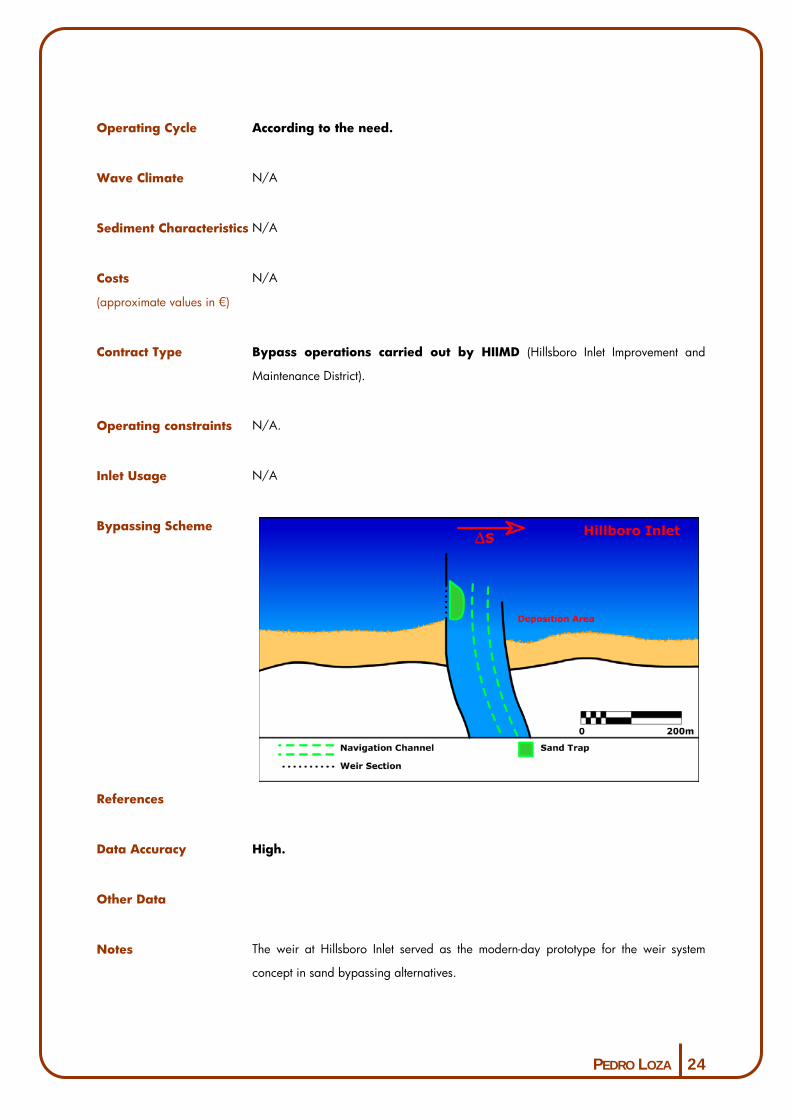
PEDRO LOZA 24
Operating Cycle According to the need.
Wave Climate N/A
Sediment Characteristics N/A
Costs
(approximate values in �)
N/A
Contract Type Bypass operations carried out by HIIMD (Hillsboro Inlet Improvement and
Maintenance District).
Operating constraints N/A.
Inlet Usage N/A
Bypassing Scheme
References
Data Accuracy High.
Other Data
Notes The weir at Hillsboro Inlet served as the modern-day prototype for the weir system
concept in sand bypassing alternatives.
PEDRO LOZA 25
Case 10 – Jupiter Inlet
Location Jupiter Inlet, Florida, USA
Type of Bypass Mobile. Operating since 1929.
Purpose Maintenance of channel navigability.
History Rock jetties were constructed by the Jupiter Inlet District in 1922 and both were
extended in 1929. The inlet closed in 1942 and was reopened in 1947. In 1956, the
north jetty was destructed and reconstructed 30 m farther north, widening the inlet. The
new jetty was constructed using concrete-caped steel sheetpile and is 900 m long. In
the late 1960’s, the jetties were modified to their present configuration. A wing was
removed from the south jetty, and both jetties are extended landward to prevent toe
erosion.
The biennial bypassing operations maintained the downdrift beach line until a violent
storm caused severe erosion in 1985. Along with the usual dredging that took place in
May 1986, a second dredging operation took place in the fall to nourish the south
beaches.
Bypass System
Characteristics
Bypass features include an inlet trap deposition basin. Net littoral drift at Jupiter Inlet is
from north to south.
Bypassing operations between 1952 and 1964 involved dredging 370 000 m3 of
material and placing it on the downdrift beaches. Since 1966, Jupiter Inlet has been
maintained by periodically dredging a sand trap located within the inlet’s protected
waters. The trap was originally dredged in 1966 with a capacity of 460 000 m3. The
dimensions of the sand trap are 60 m wide by 240 m long. The basin is about 6
meters deep, and the channel is maintained at about one meter deep. Sand trap
dredging is contracted by the inlet District approximately every 2 years, and
contractors have used 30.5- and 35.6 cm dredges.
Bypass Rate Bypassing rate: Low.
Vol med = 575 000 to 610 000 m3/year
Operating Cycle Every two years.
Wave Climate N/A

PEDRO LOZA 26
Sediment Characteristics N/A
Costs
(approximate values in �)
N/A
Contract Type Bypass operations contracted by Jupiter Inlet’s District.
Operating constraints N/A.
Inlet Usage N/A.
Bypassing Scheme
References
Data Accuracy High.
Other Data
Notes

PEDRO LOZA 27
Case 11 – Little River Inlet
Location Little River Inlet, South Carolina, USA
Type of Bypass Mobile. Operating since 1983.
Purpose Maintenance of channel depth.
History Frequent shifting of the main channel, shallow depths of the offshore bar and extensive
shoals made the inlet dangerous and, at times, impassable. Construction of the rubble-
mound jetties to improve and stabilize the inlet was approved by congress in 1972,
started in 1981, and completed in 1983. Design of the jetties was based on model
studies performed at the US Army Waterways Experiment Station (WES).
Bypass System
Characteristics
Each jetty was constructed with a closed (but sand permeable) weir section, thus
allowing sand movement through the structure and into protected depositional areas
where it would then be available for mechanical bypassing or backpassing. The weirs
can be easily opened if necessary.
The Little River Inlet jetties are quite unique because they have a weir and space for
deposition basin behind each jetty, thus recognizing the potential of significant
transport from both directions.
Gross littoral drift at Little River Inlet has been estimated at 230 000 m3 per year.
Eastward drift is estimated in 76 000 m3, and westward drift at 152 000 m3 for a net
movement of 76 000 m3 to the west. This estimate was based on the energy flux
method using wave gage data along with data from the Littoral Environment
Observations (LEO) Program. The deposition basins were designed to hold a 2-year
supply of gross sediment transport from each direction.
The updrift (east) jetty is 1000 m long with a 200-m-long weir. A 306 000 m3
trapezoidal deposition basin is planned to be dredged behind the east weir with
dimensions of 305 by 122 by 260 m and a depth of 6 m (mlw). The downdrift jetty is
3 255 m long with a 200-m-long weir. A 150 000 m3 deposition basin is planned to
be dredged weir behind the west weir with dimensions of 305 by 120 by 260 m and
a depth of 3 m (mlw). Each weir is constructed on the traditional foundation blanket,
topped by 550- to 650-kg stone with a crest elevation at midtide level (0.7 m mlw). On
top of the weir stone is an underlayer and 1.8- to 3.0-ton armor stone. The armor stone
on top of the weir stone allows sand to easily pass through, but will reduce waves
inside the jetties and reduce ebb currents through the weirs. Should the armour and
underlayer stone prove to be impermeable, they can be easily removed.

PEDRO LOZA 28
Bypass Rate N/A
Operating Cycle Every 2 years.
Wave Climate N/A
Sediment Characteristics N/A
Costs
(approximate values in �)
N/A
Contract Type N/A.
Operating constraints N/A.
Inlet Usage Little River Inlet is a shallow coastal inlet frequently used by private, sport, and
commercial fishing boats.
Bypassing Scheme
References
Data Accuracy High.
Other Data
Notes
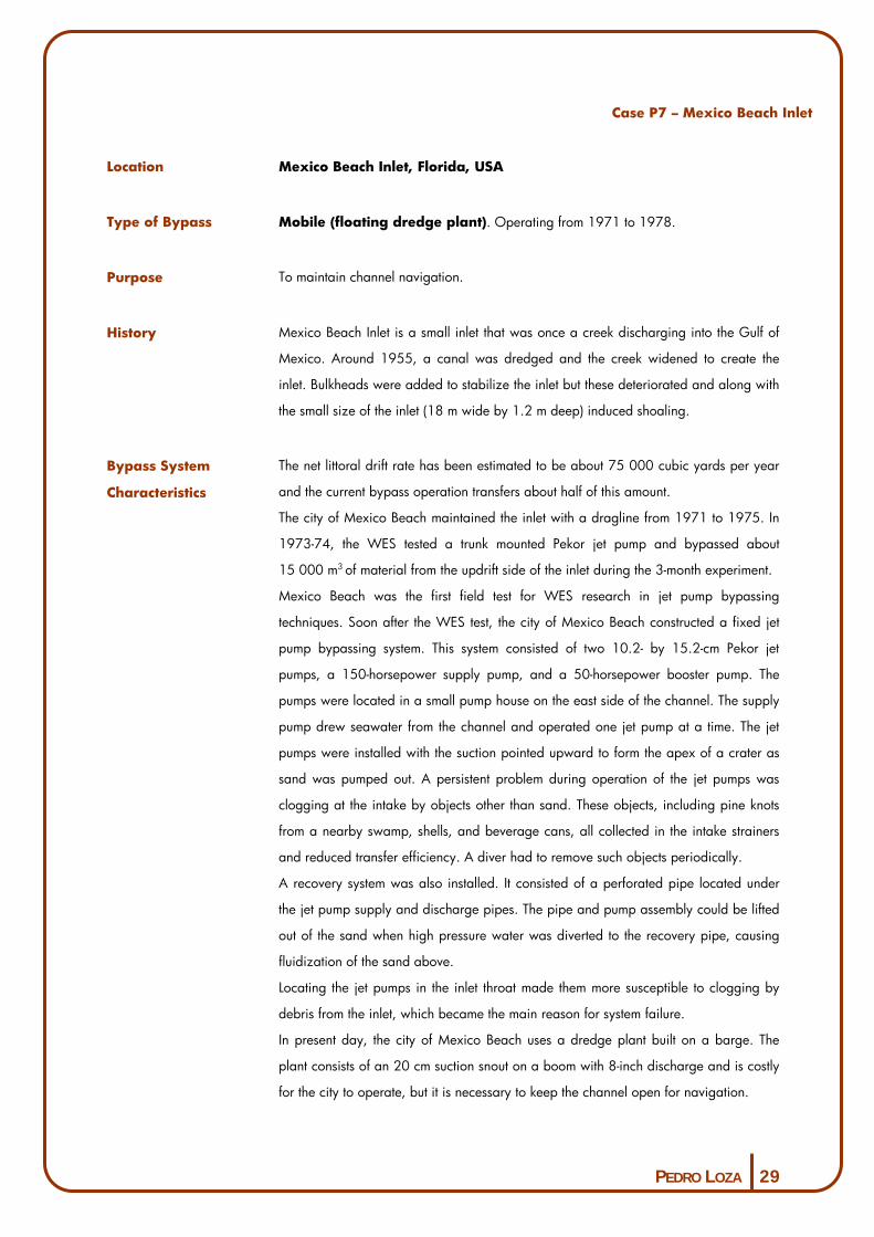
PEDRO LOZA 29
Case P7 – Mexico Beach Inlet
Location Mexico Beach Inlet, Florida, USA
Type of Bypass Mobile (floating dredge plant). Operating from 1971 to 1978.
Purpose To maintain channel navigation.
History Mexico Beach Inlet is a small inlet that was once a creek discharging into the Gulf of
Mexico. Around 1955, a canal was dredged and the creek widened to create the
inlet. Bulkheads were added to stabilize the inlet but these deteriorated and along with
the small size of the inlet (18 m wide by 1.2 m deep) induced shoaling.
Bypass System
Characteristics
The net littoral drift rate has been estimated to be about 75 000 cubic yards per year
and the current bypass operation transfers about half of this amount.
The city of Mexico Beach maintained the inlet with a dragline from 1971 to 1975. In
1973-74, the WES tested a trunk mounted Pekor jet pump and bypassed about
15 000 m3 of material from the updrift side of the inlet during the 3-month experiment.
Mexico Beach was the first field test for WES research in jet pump bypassing
techniques. Soon after the WES test, the city of Mexico Beach constructed a fixed jet
pump bypassing system. This system consisted of two 10.2- by 15.2-cm Pekor jet
pumps, a 150-horsepower supply pump, and a 50-horsepower booster pump. The
pumps were located in a small pump house on the east side of the channel. The supply
pump drew seawater from the channel and operated one jet pump at a time. The jet
pumps were installed with the suction pointed upward to form the apex of a crater as
sand was pumped out. A persistent problem during operation of the jet pumps was
clogging at the intake by objects other than sand. These objects, including pine knots
from a nearby swamp, shells, and beverage cans, all collected in the intake strainers
and reduced transfer efficiency. A diver had to remove such objects periodically.
A recovery system was also installed. It consisted of a perforated pipe located under
the jet pump supply and discharge pipes. The pipe and pump assembly could be lifted
out of the sand when high pressure water was diverted to the recovery pipe, causing
fluidization of the sand above.
Locating the jet pumps in the inlet throat made them more susceptible to clogging by
debris from the inlet, which became the main reason for system failure.
In present day, the city of Mexico Beach uses a dredge plant built on a barge. The
plant consists of an 20 cm suction snout on a boom with 8-inch discharge and is costly
for the city to operate, but it is necessary to keep the channel open for navigation.

PEDRO LOZA 30
Bypass Rate Bypassing rate:
Vol med = 30 600 m3/year
Operating Cycle On an as-needed basis.
Wave Climate The city of Mexico Beach assumes the system management.
Sediment Characteristics N/A.
Costs
(approximate values in �)
N/A.
Contract Type N/A
Operating constraints N/A
Inlet Usage N/A
Bypassing Scheme
References
Data Accuracy High.
Other Data
Notes

PEDRO LOZA 31
Case 12 – Masonboro Inlet
Location Masonboro Inlet, North Carolina, USA
Type of Bypass Mobile. Operating since 1959.
Purpose To maintain navigational channel position.
History Masonboro Inlet is a natural inlet, first dredged in 1959. Rapid shoaling of the channel
forced the US Army Engineer District (USAED), Wilmington, to stabilize the inlet by
construction of a north jetty between 1965 and 1966. At the direction of higher
authority, the construction also included the prototype weir section and deposition
basin. The north jetty consists of an inner section of concrete sheet piles 520 m long (of
which 305 m is the weir section) and a rubble mound outer section 580 m long. The
elevation of the weir section is at midtide level (tide range is 1.2 m), +2 feet above
mlw. The basin was first dredged to a depth of 16 feet mlw and had a capacity of
280 000 m3. Soon after the jetty was completed, the channel migrated north through
the deposition basin and along the north jetty. This migration of the channel caused
two problems:
- the deep channel (7.6 to 9.2 m) threatened to undermine the structure;
- the channel passed through the deposition basin, preventing it from accumulating
sand for bypassing.
The scour problem caused by position of the channel against the structure continued in
the 1970’s, forcing repairs to the structure and the placement of additional toe
protection. This problem and the threat of a major collapse due to the currents and
scour associated with a major hurricane led to a physical model study by WES. The
selected plan included the south jetty, a centralized ocean entrance channel and a
segmented training wall between the inlet and deposition basin.
When the plan was implemented, construction of the training wall was deferred for
two reasons: first, the training wall would have had to be constructed in areas with 25-
to 30-foot depths with strong tidal currents flows making construction difficult and
expensive; second, it was desirable to allow the inlet zone between the two jetties to
stabilize t a new equilibrium condition prior to training wall construction since model
testing could not conclusively establish the exact structure configuration.
In 1980, the south jetty was completed and 920 000 m3 of material was dredged
from the navigation channel and from shoals within the inlet. In 1981, dredging to
center the entrance channel was done and the need for a training wall was eliminated.
The entrance channel is located between the two jetties and it’s 15 to 20 deep.

PEDRO LOZA 32
From a bypassing standpoint, the most interesting feature of the newly established inlet
is the change in the deposition basin. The area of deposition has expanded
considerably to include the original deposition basin and section of the inlet throat and
an expansion area at the intersection of the inlet throat and Banks channel and a
section of the Banks Channel. As so the majority of material would pass over the weir
in the vicinity of the shoreline-weir interface. Therefore, the landward portion of the
deposition basin should be the widest section. If the weir orientation was closer to the
upper limit of current design guidance of 60 degrees instead of 85 degrees
(constructed) with respect to the shoreline, the deposition basin would have greater
capacity. However, the present configuration is working very well with the expanded
deposition basin in the inlet throat and Banks Channel effectively overcoming the limits
on the weir-shoreline imposed by lack of available land.
Bypass System
Characteristics
The inlet is maintained by a Federal navigation project incorporating a jetty with a
weir section, deposition basin, and contracted dredging for bypassing and
backpassing. Current authorized channel dimensions are 120 m wide and 4.3 m deep
at 1 mlw.
Between 1967 and 1979, all dredging operations involved channel maintenance. The
1986 dredging of the inlet removed approximately 690 000 m3 of sand from between
the jetties and placed it on Wrightsville Beach. Another 1.1 million cubic yards was
dredged from the south end of the Banks Channel and bypassed to Masonboro Island.
The beaches around the inlet have reached equilibrium and no further shifting is
expected. Since the construction of the south jetty, no dredging has been required at
the seaward end of the navigation channel. The expansion of the sediment trap has
proved to be very beneficial regarding costs.
The increased deposition basin only requires dredging approximately every 4 years,
reducing the mobilization/demobilization percentage of the unit cost considerably.
Bypass Rate Bypassing rate: Medium.
Vol med = 215 000 m3/year
Operating Cycle Every 4 years, or according to need.
Wave Climate N/A
Sediment Characteristics N/A
Costs N/A

PEDRO LOZA 33
Contract Type The inlet is maintained by a Federal navigation project.
Contracted dredging for bypassing and backpassing.
Operating constraints N/A.
Inlet Usage N/A.
Bypassing Scheme
References
Data Accuracy High.
Other Data
Notes

PEDRO LOZA 34
Case 13 – Ponce de Leon Inlet
Location Ponce de Leon Inlet, Florida, USA
Type of Bypass Mobile. Operating since 1969.
Purpose To stabilize and increase the depth of the channel.
History Before the navigation works took place, the inlet suffered from a shifting channel and
shallow depths over the ebb-tidal delta. The 1 235-m-long north jetty consists of a
150-m section of concrete sheet-piles, 550 m of weir (originally), and a 533-m-long
rubble-mound outer section. The first 300 feet of the weir were at an elevation of +1.2
m mlw, while the remaining 457 m was at an elevation of 0.0 mlw. The1 160 000-m-
long south jetty is entirely of rubble-mound construction. A trapezoidal impoundment
basin was positioned between the north jetty weir and the channel and has dimensions
of 380 by 213 by 113 m. The basin was dredged to a depth of 6 m mlw and had a
volume of 306 000 m3.
Bypass System
Characteristics
The weir length and elevation were based on data available at the time of design. The
gross littoral transport rate was estimated at 535 000 m3 per year, though the data
available estimates that from 1956 to 1975 the average net drift of 97 000 m3 per
year to the south and a gross drift of 400 000 m3. Coastal Engineering Research
Centre guidance has shown that the weir should be one-fourth of its original length and
0.6 m higher.
The original weir allowed significant ebb flow to pass over it, encouraging the channel
to migrate through the deposition basin and against the north jetty. It also allowed a
substantial amount of wave energy to pass over and into the inlet waters.
Bypass Rate Bypassing rate: High.
Vol med = 535 000 m3/year (design value)
Operating Cycle The dredging operations are contracted when necessary.
Wave Climate N/A
Sediment Characteristics N/A

PEDRO LOZA 35
Costs
(approximate values in �)
N/A
Contract Type The USAED was responsible for the jetties construction.
The dredging operations are contracted when necessary.
Operating constraints N/A.
Inlet Usage N/A.
Bypassing Scheme
References
Data Accuracy High.
Other Data The weir closure has stabilized the beach north of the inlet ant the channel. Erosion is
not a problem for the beaches downdrift of Ponce de Leon Inlet; therefore dredging
operations are directed toward channel maintenance. This fact led to problems
concerning the deposition location for the sand dredged during maintenance at the
inlet.
Notes

PEDRO LOZA 36
Case 14 – Santa Barbara
Location Santa Barbara, California, USA
Type of Bypass Mobile. Operating since 1927.
Purpose To maintain the harbour and entrance channel at Santa Barbara.
History A 550-m-long detached breakwater was constructed in 1927-28, creating the harbour.
The detached construction greatly reduced local wave energy, resulting in a fast
shoaling of the harbour. Consequently, a 172-m extension to shore on the west end
was constructed in 1930. Such system interrupted natural littoral drift and resulted in
erosion of the east beaches. By 1937, a sand spit had formed at the end of the
breakwater. It provided further protection for the harbour, and by the early 1950’s, the
city of Santa Barbara decided not to remove it. To prevent wave overtopping, the city
built a 228-m-long timber bulkhead and rubble-mound wall along this bar. The wall
provided stability, but it directed littoral material into the channel entrance. In October
1985, local stakeholders completed a 73-m rubble-mound extension to the sand spit
breakwater to provide further harbour protection.
Bypass System
Characteristics
Bypassing operations began in 1938 using hopper dredges, but were unsuccessful. In
1938, the bypassing operation successfully used a pipeline dredge to transfer material
to the downdrift beaches. Present day bypassing operations continue with this
procedure, and the present contractor uses a 40,6 cm cutterhead suction dredge. The
designated disposal area is 700 m downcoast of the harbour and is about 1220 m in
length (along the beach). Emergency dredging operations sometimes take place.
Disposal was allowed within a 152 m zone with submerged discharge into the surf
zone to minimize turbidity.
The beaches directly east to the harbour (feeder beach area) are stable and well
maintained by the dredging efforts. However, beaches farther downcoast still suffer
erosion, thus indicating that present bypassing rate is not enough. Shoaling rates
dictate annual maintenance dredging of the4.6- to 9.2 m entrance channel.
Bypass Rate Bypassing rate: Medium.
Vol med = 250 000 m3/year
Operating Cycle Annually.

PEDRO LOZA 37
Wave Climate N/A
Sediment Characteristics N/A
Costs
(approximate values in �)
N/A
Contract Type The harbour and entrance channel are maintained by the USACE through
contracted dredging operations.
Operating constraints Environmental concerns limit dredging to the winter months between September and
March, often the most difficult time to operate dredging equipment.
Inlet Usage N/A.
Bypassing Scheme
References
Data Accuracy High.
Other Data
Notes

PEDRO LOZA 38
Case 14 – Sebastian Inlet
Location Sebastian Inlet, Florida, USA
Type of Bypass Mobile. Operating since 1962.
Purpose To maintain channel navigability and to prevent further beach erosion.
History Sebastian Inlet was opened and stabilized with two jetties in 1948. The jetties were
extended in 1970 and have been identified as a major cause of natural longshore drift
interruption. The jetty extensions are of semi-porous rubble-mound construction that
allows some sand to enter the inlet throat and be transported by flood currents to the
flood-tidal delta. The entire inlet cross section was cut through solid coquina limestone.
The rock perimeter limits the cross-sectional area to about half of what would be
expected, considering the tidal prism admitted. Flood-tidal currents are therefore strong
and carry littoral material a considerable distance through the inlet.
Bypass System
Characteristics
Bypass is accomplished with a floating dredge working in the inlet’s deposition basin.
The first deposition basin was dredged at the juncture of the inlet throat and lagoon in
1962, and it had a volume of 210 000 m3. A larger trap was dredged in 1972 with a
volume of 325 000 m3. In 1978, the basin was dredged and 144 000 m3 were
bypassed to the south beaches. All of these operations involved pumping the material
directly to the beach from the dredge. In 1985, a fourth sand bypassing operation was
carried out at Sebastian Inlet. This project involved dredging the sand trap, filling a
holding basin on shore, and transporting the sediments with trucks to the south beach.
The beaches south of the inlet have eroded severely since the construction of the jetties
and their extension in 1970. The dredging operations have maintained the navigation
channel, but the south beaches continue to suffer a net annual loss of material. A
substantial accumulation of material at the north jetty fillet and a diversion of sand into
the ebb-tidal shoal and out to an offshore bar are the primary reasons for sand lost to
the downdrift beaches.
Bypass Rate Bypassing rate: Medium.
Vol med = 190 000 m3 (values vary from 144 000 to 325 000 m3)
Operating Cycle The basin has been dredged four times since 1962.

PEDRO LOZA 39
Wave Climate N/A
Sediment Characteristics N/A
Costs
(approximate values in �)
N/A
Contract Type N/A.
Operating constraints Environmental concerns over the impact of the project on the local rock reef system
induced a change in bypassing procedure. Since 1985, all sand is carried in trucks
from a holding basin on shore to the deposition beaches.
Inlet Usage N/A.
Bypassing Scheme
References
Data Accuracy High.
Other Data
Notes

PEDRO LOZA 40
Case 15 – Rudee Inlet
Location Rudee Inlet, Virginia, USA
Type of Bypass Semi-Mobile. Operating since 1970’s.
Purpose To create a navigable channel and prevent further beach erosion (maintaining the
deposition basin and entrance channel).
History Prior to 1952, Rudee Inlet was essentially non navigable. It had existed in its natural
state since 1927, when a concrete flume was built to canalize the inlet’s tidal flow. In
1952, two short jetties were constructed, and a navigation channel was dredged
between them. At the same time, approximately 1 000 000 m3 of material were
dredged from small estuaries behind the inlet and placed on downdrift beaches. Soon
after construction of these jetties, the inlet began to fill with littoral sand, and
corresponding erosion began on the downdrift beaches. A small capacity fixed
bypassing system (50 cubic yards) was installed in 1955 but had little or no impact
whatsoever. The city of Virginia Beach bought in 1956 a floating pipeline dredge, but
even so erosion was stopped. In 1962, the fixed system was destroyed by an extra-
tropical storm. In 1963 the channel had essentially closed and natural sand bypassing
resumed.
The inlet remained in this condition until 1968 when stabilizing structures where built
and the channel was dredged. The structures consisted on a jetty downdrift (north) side
of the inlet and a breakwater connected to shore by a sand weir on the updrift (south)
side.
A dredged impoundment basin was proposed. This basin would catch and hold littoral
material passing over the weir. Periodic dredging of the basin was expected to prevent
channel shoaling and provide sand for nourishment of downdrift beaches. Contrary to
the maintenance plan, operation of the inlet’s 10-inch dredge in the basin was
hampered by wave action, and the basin was never fully dredged. From 1968 to
1972, bypassing of the inlet consisted of a 25.4 cm dredge operating in the channel
and estuaries. Material was pumped to downdrift beaches, but erosion persisted. In
1972, a large floating dredge was contracted and bypassed 77 000 m3 from the
basin along with another 153 000 m3 from the channel and estuaries. The
impoundment basin had refilled by 1975, and the city dredge resumed bypassing.
Presently, a stretch of recreational beach downdrift of the inlet is reasonably well
maintained due to bypassing and seasonal drift reversal. Beaches farther downdrift
and those beyond the reach of the bypassed sand still suffer erosion.

PEDRO LOZA 41
Bypass System
Characteristics
An experimental jet pump system was installed in the impoundment basin by WES in
1975. The WES system consisted in two jet pumps, each attached by a flexible rubber
hoses to steel pipes which extended into the basin. The ends of the steel pipes served
as pivoting points for the jet pumps to swing across a large area in the basin. The jet
pumps were positioned from shore, using cables. The pump house was situated next to
one of the original short jetties. It housed the clear water supply pumps, one for each
jet pump, and one slurry booster pump for the combined discharge of both jet pumps.
Discharge flowed through a 20.3 cm steel pipeline to a point 670 m downdrift of the
inlet. The nominal capacity of each jet pump was 57 m3 per hour for a combined
capacity of 114 m3 per hour. The system was operated by WES on an experimental
basis of 6 months. During this time approximately 30 000 m3was bypassed from the
impoundment basin. Along with operation of jet pump system, the city dredged about
0 23 000 m3 from the channel and impoundment basin during the same 6 months. The
jet pump system was expected to be capable of bypassing the net drift and was sold to
local authorities at the end of the experiment.
Bypass Rate Bypassing rate: medium.
Vol nominal = 115 m3/hour (experimental period of 6 months)
Vol med = 300 000 m3/year
During the 6 month experiment period, bypassing of about 60 000 m3 was
complemented with a 23 000 m3 from the channel and impoundment basin. Therefore,
the total bypassing capacity of the test was estimated in 170 000 m3/year.
Operating Cycle The jet pump system was used intermittently to clear the deposition basin until 1987.
The 14-inch city dredge now operates intermittently throughout the year.
Wave Climate N/A
Sediment Characteristics N/A
Costs
(approximate values in �)
N/A
Contract Type The floating dredge, 35.6 cm cutterhead dredge and semi-mobile jet pump are now
owned by the city of Virginia Beach.

PEDRO LOZA 42
Operating constraints The dredge is still unable to fully maintain the deposition basin because of wave
action.
Inlet Usage N/A.
Bypassing Scheme
References
Data Accuracy High.
Other Data
Notes

PEDRO LOZA 43
Case 16 – Santa Cruz
Location Santa Cruz, California, USA
Type of Bypass Mobile. Operating since 1962.
Purpose To maintain channel entrance and allow safe navigation.
History The artificial inlet was dredged through a narrow beach in 1962, when two entrance
jetties were also constructed. The construction of the inlet immediately interrupted
natural sand transport. The updrift beach experienced significant accretion, while the
downdrift beaches eroded and severe channel shoaling took place. The continuous
shoaling closed the harbour and only a small tidal channel remained.
The harbour has a history of closure during the winter month due to storms and rapid
shoaling rates. In the first year of dredge pumping operations in 1986 the channel
kept open through the whole year.
Bypass System
Characteristics
In 1976, WES began field testing an experimental sand bypassing system. The system
employed five jet pumps, of which only one was fixed. The severe wave climate
hampered jet pump positioning at Santa Cruz; and rapid shoaling rates buried the jet
pumps supply and discharge lines, causing further positioning operations difficult. With
proper backflushing, the system was able to perform properly. Though the rapid storm
shoaling rates during the winter months presented a challenge for the jet pump system
operators, but the system was operational for about 2 years.
In October 1986, after ten years of contract dredging, the Corps of Engineers
purchased and donated to the Santa Cruz District a new 40.6 cm a cutter section
dredge with an optional jet nozzle suction head.
The dredge is operated primarily with the jet nozzle suction head and has proved
efficient in maintaining the channel entrance. The port district uses a method of
dredging they call “pothole dredging” – it involves the pumping of a hole at a given
location and then swinging the dredge over to excavate another hole, and so on.
Significant down time as been reported due to dredge pump blockages.
All the material dredged is placed on the downdrift beaches.
Bypass Rate Bypassing rate: low.
Vol med =70 000 m3/year

PEDRO LOZA 44
Operating Cycle Annual. Channel maintenance initiated in 1965. Usually a 30.5 cm pipeline dredge
was mobilized in late winter, and the channel was cleared by early spring.
Wave Climate N/A
Sediment Characteristics N/A
Costs
(approximate values in �)
N/A
Contract Type The Corps of Engineers contracted maintenance dredging until 1986, when
Santa Cruz Port District took responsibility for harbour and channel maintenance.
Operating constraints N/A.
Inlet Usage N/A.
Bypassing Scheme
References
Data Accuracy High.
Other Data
Notes

PEDRO LOZA 45
Case 17 – Ventura Marina
Location Ventura Marina, California, USA
Type of Bypass Mobile. Operating since 1972.
Purpose To avoid sediment deposition in the channel and harbour area to maintain
navigability.
History In 1963 the jetties and entrance channel were constructed by local authorities. In
1968, the Federal Government assumes responsibility for maintenance dredging in
Ventura Harbour. Construction of the offshore breakwater and sand trap was
completed in 1972. The project in Ventura Marina was designed to dredge and
bypass 600 000 m3 of material once every two years.
Bypass System
Characteristics
Ventura Marina is a man-made commercial and recreational harbour, which
experiences hazardous navigation conditions since it was constructed.
Sediments accumulate at such a high rate that the entrance channel must be dredged
frequently to maintain the channel depths of 6 to 9 m (mlw). Bypassing operations
have taken place 14 times over the past 16 years, and dredge volumes indicate an
average annual accumulation of over 600 000 m3. Sediment moving from the north is
effectively trapped in the deposition basin behind the offshore breakwater, and
entrance channel shoaling normally does not become a problem until the basin is filled
to capacity. However, no system has been developed to control the summer reversal in
longshore drift direction (south to north). This reversal can be significant when the south
beach is in a nourished condition or when the Santa Clara River (located south of the
harbour) floods. Bypassing has taken place from the channel for maintenance purposes
even when the deposition basin was not filled to capacity. At times, the shoreline south
of the south jetty recedes and shoaling tends to diminish.
Most of the material dredged is bypassed about 1 mile south, to widen and maintain
beaches. The beaches directly to the south of the Ventura Marina are nourished every
few years according to need. The northern beaches, directly north of the north jetty,
eroded and required stabilization with riprap.
Bypass Rate Bypassing rate: High.
Vol med = 600 000 m3/year

PEDRO LOZA 46
Operating Cycle Once a year (bypassing operations have taken place 14 times over the past 16
years).
Wave Climate N/A.
Sediment Characteristics N/A.
Costs
(approximate values in �)
N/A.
Contract Type Contracted dredging is a Federal Government responsibility since 1968.
Operating constraints N/A.
Inlet Usage N/A.
Bypassing Scheme
References
Data Accuracy High.
Other Data Ventura Marina can be considered a successful project concerning beach nourishment;
however, rapid channel shoaling and resultant navigation hazards have led to the
development of proposals to improve the project for navigation.
Notes

PEDRO LOZA 47
Case 18 – Port Sanilac
Location Port Sanilac, Michigan, USA
Type of Bypass Fixed. Operating since 1958.
Purpose To assure sand bypassing through various harbours on the Great Lakes.
History Port Sanilac is a small-raft harbour on Lake Huron, located about 65 miles north of
Detroit.
Bypass System
Characteristics
Major systems components were mounted on a 12 m flatbed trailer and included the
following: fuel tank, generator set, air-compressor, control room, power supply
regulators, water supply pump with diesel engine driver, booster pump with diesel
engine driver, and piping valves. Monitoring instruments were housed in a separate,
enclosed trailer.
The system was designed to be driven onto an accretion fillet where the jet pump could
be deployed and operated in the nearshore zone. Vertical motion could be controlled
by changing the amount of air in the float. Horizontal motion between successive
craters could be controlled by opening a water jet on the jet pump supply line.
Discharge would be carried along the harbour bottom to downdrift beaches.
Bypass Rate Bypassing rate: low.
Vol med = N/A.
Operating Cycle N/A.
Wave Climate N/A.
Sediment Characteristics N/A.
Costs
(approximate values in �)
N/A.
Contract Type A portable, truck-mounted jet pump system was built by WES.
The Michigan State acquired the system in July 1988.

PEDRO LOZA 48
Operating constraints System technicians have reported that the system worked extremely well for the
designed purpose. However, resistance by updrift property owners often precluded
accretion fillet operation. The system was used mainly as a rehandling device for
material release by hopper dredges. For this purpose, it was driven onto a barge and
operated as a floating dredge.
Inlet Usage N/A.
Bypassing Scheme
References
Data Accuracy High.
Other Data
Notes