master of architecture design portfolio
DESCRIPTION
This is my current architectural portfolio which contains selected projects from the entirety of my education. The first four projects are works completed while in graduate school at the University of Texas San Antonio, and the following four works were completed as an Undergraduate at Kent State University. Also included are sketch work, rendering, and a sustainability research project.TRANSCRIPT

1
DESIGN PORTFOLIO
DAVID T. STUMPF
Kent State UniversityBachelor of Arts in Architectural Studies
Construction Management
The University of Texas San Antonio
Master of Architecture

2
INDEXGraduate Design Work The Crockett Gallery 4 The S.A. Exchange Tower 7 The Land Heritage Institute 11
Graduate Research Green Print 15
Undergraduate Design Work Cleveland S.R.O Housing 19 gate | WAY 22 Behavioral Dwellings 24 Sculpture | Site Expansion 26
Design Support Rendering 28 Sketch Work 32
Certifications Building Performance Analysis 35


4Concept Design
The C
rockett Gallery
of Contem
porary sculpture
During the initial design phase it was decided upon that the structure to be placed on the site of the ex-isting sculpture garden would act as an addition to the sculpture garden. This new structure would be a gallery for smaller sculptural works that would not be able to be placed outside, but instead would need a controlled indoor environment. The Crockett Gallery would become a sculptural work in its own right, by building upon the perceived rules of solid vs. void, and line vs. plane that the designer had created for the existing sculpture garden the Gallery would look and feel as if it had always been a part of the garden.

5
Key Concepts:
- Linear Play of the site- Verticality- Monolith- Pay homage with existing sculpture garden with a new structure
Basement
1st Floor
2nd Floor

6
View of River Walk Stairs

7
The S.
A. E
xcha
nge
Tow
er
S.A. Exchange Tower
Objectives:
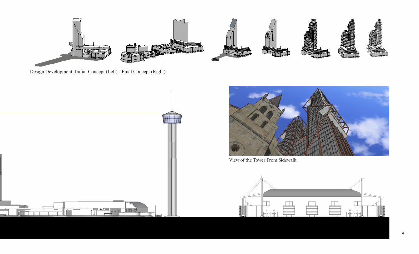
The S.A. Exchange Tower was developed through a preservation studio as an upward expansion from the existing Joske Building in downtown San Anto-nio, TX. The S.A. Exchange tower was developed so that the shadow cast during the winter solstice would miss the Alamo while still achieving the maximum height possible, and still stay below the observation deck of the Tower of the Americas. At 40 stories the shadow path avoids the Alamo due to the creation of a steep slope in the building’s north facade.
View of the S.A. Tower facing the Alamo

8
AlamoJoske Building
View From I-35 South View South From Commerce Street
9
View of the Tower From Sidewalk
Design Development; Initial Concept (Left) - Final Concept (Right)

10
Winter Solstice Sun-Path Study
3D Section Cut through the Exchange Tower

11
The La
nd H
erita
ge In
stitu
teV
isito
r Cen
ter The Land Heritage Institute
Visitor Center
The Land Heritage Institute is a non-profit organi-zation south of San Antonio Texas who’s mission is to inform and educate about the history of land use in Texas. The Land Heritage Institute required the development of a visitor center that would act as a reception area for visitors, as well as an area which small groups would be able to use as a meeting space. The programing of this facility required the inclusion of a prep-kitchen, an office for a park employee, restroom facilities, meeting/gathering spaces, and storage.
3D Section Cut
3D Section - Floor Plan

12
Development:
Because this building was to be used as a visi-tor center for an institution that taught about how people in the past lived on the land in Texas, and the request of the organization to keep the building light on the land the traditional styling of the “dog trot” was selected. The “dog trot” styling allowed for the creation of a six bay structure, where every other bay would act as a breeze way between the functional elements of the structure just as a “dog trot” would.
Objectives:
Create a design development set that was technical-ly accurate, and properly articulated the construc-tion of the designed building.
Develop a building that would meet the needs of the Land Heritage Institute: - To be Volunteer Constructed - Light on the land - Meeting Space, Restrooms, Kitchen, and Storage - Re-develop entry into the site

13

14

15
Gre
en P
rint Greenprint is a 970 square foot, one bed-
room, one bath home designed as a possible candidate for The University of Texas at San Antonio’s entry into the Solar Decathlon. A competition in which teams from universi-ties all over the country design, build, and test that their designs are “net zero.” The central dining space opens up to two shaded porches and is intended to be a multi-use in-door/outdoor room. The open kitchen plan, featuring Energy Star appliances, opens up to the entertainment room allowing expansion for larger parties, such as the home enter-tainment competition.
Structural Model

16
1.Bedroom 100 SF2. Mechanical 40 SF3. Bathroom 80 SF4. Dining 250 SF 5. Living Room 55 SF6. Kitchen 128 SF7. Breakfast Bar 8. Shaded Entrance 9. Shaded Porch
Total Square Feet: 970 SF
CNC Cut Green Print Shell
CNC Cut Green Print Shell Section
One of the primary designs parameters for this project was for “everyone” (meaning an average person anywhere in the world) to be able to build, expand, or design their own home in such a way that they can do it them selves or with very little help. To do this the idea of using a CNC router to cut the structure of Green Print from plywood was explored. This idea is still based heavily in theory and to explore the ability of building in this was took an evolutionary path, as well as the mock-up of several physical models. The design of the struc-ture we came up with for Green Print can change or evolve, and is intended to do so depending on the whim, location, monetary resources, or life style of the owner.

17
Passive Design Systems - Plan
The layout and massing of Greenprint (shown in Figures 8-11) are optimized to take advantage of prevailing breezes in both San Antonio and Irvine. An H-shaped plan allows for easy passage of breez-es through each room of the house for good cross ventilation, with more windows located on the inlet side and fewer, smaller windows on the outlet side to encourage airflow. High vaulted ceilings and operable skylights on the north-facing roof surfaces serve as outlets to encourage stack ventilation as well. Concerning daylighting and shading, the main living areas, bedroom and bathroom will receive natural light from multiple directions. Awnings and trellises will protect south, east and west facing areas of glazing. On the south side, awnings will block all direct summer sun as well as some winter sun – ex-cessive solar heat gain being an issue in San Antonio even in the wintertime.
Wind Charts Climate Analysis (San Antonio, TX and Irvine, CA)
Wall Detail

18
Wall Section
Integrated Rain Water Harvesting SystemIntegrated Rain Water Harvesting System - Section
Active Heating and Cooling Systems
Integral Water Storage:
The storage tanks under the home allow for add-ed insulating properties when filled. They are also design to expand and contract as a bladder would when water is filling or draining from the system.
Active Systems:
ERVRadiant Cooling - Ceiling PlacementRadiant Heating - Floors PlacementFlat Plate Solar CollectorThin Film PV Systems

19
Cle
vela
nd S
.R.O
. Hou
sing Single Room Occupancy (S.R.O.)
Objectives:
Create a facility for homeless and low income indi-viduals, that consists of twenty single room apart-ments, a building manager’s apartment, offices, 3 common rooms, building utilities, attached market, and no more than three levels in height.
Site Map
Interior Perspective | Community space

20
Site:
The site is a corner lot in downtown Cleveland, OH. It is divided into two sections because of a small ac-cess road for an elementary school in the rear of the site. The road had to be maintained and the build-ing had to be designed around it without disrupting any possible traffic.
Original Model Scale: 1/8” = 1’

21
The S.R.O.:
Each individual room contains a kitchenette, bath-room, built-in closet space, sitting space, and sleep-ing space.
First Floor Plan
Second Floor Plan
Third Floor Plan

22
gate | WAY
Objective:
Create a functional “gateway” to Kent, Ohio. The site is located on the northeast corner of the inter-section of state routes 43 and 59. The “gateway” should reflect the town of Kent, Kent State Univer-sity, a connection between the two and maintain its visibility all year round. Materials utilized should reflect the university and city’s commitment to sus-tainability.

23Investigation: Materials + Assembly
Preliminary Design Drawings

24
Behavioral Dw
ellings
Design/Program:
Mixed use high-rise book store, coffee shop, and storage spaces on the first level, with unified dwell-ing units (single (1 bedroom) & family (3 bed-rooms) all of which are two floors in height) above the commercial space.
Form Parti = Monolithic/Interpenetrated/Separat-ed+linked
Additive application of Point/Line/Plane = Solid/Void

25
Objectives:
1 - Design two life cycle dwelling units based on behavioral settings required.
2 - Create qualitative/quantitative spatial experi-ences applicable to the required behavioral settings and reinforce individual components as integral elements of a single collective whole internally and externally.
Design Diagrams

26
Sculpture | Site Expansion
Objective:
The designer is to gain understanding of the creative processes of sculpture and the thought processes be-hind its creation. Take the knowledge gained in this research and create a two piece sculpture to fit in the designated site maintaining height and overhang limits. The sculpture is to be created of only basic geometric shapes and limits. Once the final sculp-tural model is achieved it is then converted into a structure in the form of a museum or art gallery.
Exterior
Interior
Main concept:
Site expansion through “Sculpture.” Structure and usable interior spaces through the well thought out conversion of a created sculpture.

27
West Elevation
Original Model Scale: 1/8” = 1’
Original Drawing Scale: 1/8” = 1’
Issues Considered: sculpture connection geometry assembly movement structure

28
Rendering

29
Class: Computing Media for Architectural Studies
Project: Realistic rendering from a AutoCAD drawn elevation utilizing Adobe PhotoShop.
The basis of this project was a mixed-use high-rise our profes-sor had designed to be located in Florida. As reference we were given the original rendering, along with an AutoCad drawing of the west elevation. We utilized only Adobe PhotoShop, and the skills we acquired in the class to create our final renderings of this project.
West Elevation

30
Programs Used: AutoCad, Revit Architecture, 3dsMax, Photoshop, RhinocerosClass: Computer Applications in Architecture II
Project: For the final the class was given the spe-cific task of creating model furniture from scratch using the 3D modeling program Rhinoceros from plans created in AutoCAD. From there we import-ed our models into Revit Architecture in which the room was created. Following this we took the revit model of the room and all the furniture and accessories, and imported it into 3dsMax where we rendered all of the objects to create photo realistic quality. Finally Photo Shop was used to clean up any imperfections in the images.
31
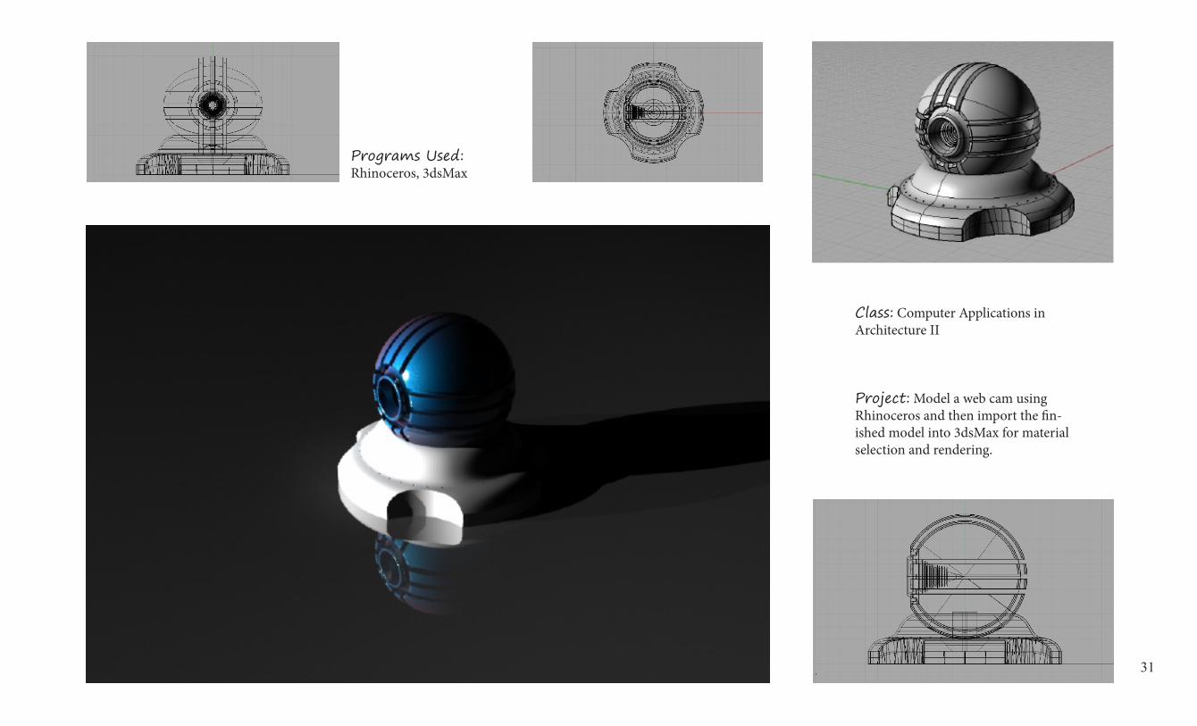
Class: Computer Applications in Architecture II
Project: Model a web cam using Rhinoceros and then import the fin-ished model into 3dsMax for material selection and rendering.
Programs Used: Rhinoceros, 3dsMax

32
Sketch Work
The following are selections of sketch work that I believe show my abilities of drawing/sketch-ing, diagramming through drawing & sketch work, and understanding design and struc-ture through drawing & sketch work.

33

34

35
The Autodesk Education team hereby congratulates
for successfully completing the Autodesk Building Performance Analysis Certificate.
The recipient is now better prepared to apply building science concepts in the creation ofhigh-performance buildings and put that knowledge into practice with Autodesk software.
BPAC v1.0 - August 2013
TOPICS: Intro to BPA, Climate, Energy Literacy
Sun and Shadows, Solar Radiation, Whole
Building Energy Analysis, Airflow, Daylighting
SOFTWARE: Autodesk Revit, Vasari, GBS
May 09 2014
David Stumpf
Powered by TCPDF (www.tcpdf.org)
1 / 1