massive mimo systems in noncontiguous bands with ...hxm025000/rfdd-proofread.pdfieee transactions on...
TRANSCRIPT
IEEE TRANSACTIONS ON WIRELESS COMMUNICATIONS, VOL. 15, NO. 7, JULY 2016 4689
Massive MIMO Systems in NoncontiguousBands With Asymmetric Traffics
Hlaing Minn, Fellow, IEEE, and Amin Khansefid, Student Member, IEEE
Abstract—Massive MIMO systems offer large spectrum effi-ciency improvements but when applied to systems with non-contiguous bands as commonly encountered in practice, theirperformance gains are largely offset by the overhead in acquir-ing channel state information (CSI). This paper presents threeschemes to enable overhead-efficient massive MIMO in noncon-tiguous bands with frequency-selective channels. By incorporatingCSI errors, CSI overhead, pilot contamination, and guard inter-val cost, achievable rate or throughput expressions of uplink anddownlink of the proposed schemes are derived. Novel resourceadaptation mechanisms between uplink and downlink are pro-posed and analyzed. Compared with the conventional frequencydivision duplexing scheme, analytical/numerical studies elabo-rate substantial spectrum efficiency enhancement, and flexibleresource adaptation capability of the proposed schemes.
Index Terms—CSI overhead, Massive MIMO, Multi-band TDD,Non-contiguous bands, Resource adaptation, Rotating FDD.
I. INTRODUCTION
L ARGE-SCALE antenna technology also known as mas-sive multi-input multi-output (MIMO) can substantially
enhance spectrum and energy efficiency [1] and has emergedas an enabler for next generation wireless systems [2]. The keyingredient for massive MIMO is the base station (BS)’s knowl-edge of individual channel state information (CSI) of all ofits user equipments (UEs) for both uplink (UL) and downlink(DL). For a system with a single contiguous band using timedivision duplexing (TDD), CSI of UL and DL can be obtainedthrough the use of UL pilots and channel reciprocity. The pilotoverhead is generally proportional to the number of total trans-mit antennas [3], and that number is smaller for UL than DLin massive MIMO systems, which justifies the approach of ULpilots. Due to the natural fit of TDD to the CSI need of massiveMIMO, most existing massive MIMO works (e.g., [3], [4] andreferences therein) in the literature consider TDD systems.
Spectrum allocations using non-contiguous bands are quitecommon, e.g., see LTE frequency channels [5], due to pre-existing spectrum allocations and non-availability of a sufficientsingle contiguous band. For such scenarios, the UL and DL of
Manuscript received March 3, 2015; revised September 11, 2015, December22, 2015, and February 17, 2016; accepted March 11, 2016. Date of publicationMarch 22, 2016; date of current version July 8, 2016. This work was supportedin part by the National Science Foundation under Grant 1547048. The associateeditor coordinating the review of this paper and approving it for publication wasA. Wyglinski.
The authors are with the University of Texas at Dallas, Richardson, TX 75080USA (e-mail: [email protected]; [email protected]).
Color versions of one or more of the figures in this paper are available onlineat http://ieeexplore.ieee.org.
Digital Object Identifier 10.1109/TWC.2016.2544753
a system operate in different bands, which is commonly knownas frequency division duplexing (FDD). An advantage of FDDsystems is that under a peak power constraint, they offer largercoverage than TDD systems. However, as UL and DL CSIsare different in FDD systems, acquiring individual DL CSIsfor massive MIMO operation would require too excessive over-head. This overhead issue stands as a major limitation of mas-sive MIMO in FDD mode. There are only a few works on mas-sive MIMO with FDD in the literature. They include low com-plexity CSI quantization [6], precoding schemes to reduce CSIoverhead by exploiting spatial correlation of the channels acrossBS antennas [7], [8], and open-loop and closed-loop trainingmechanisms exploiting temporal correlation of the channels toreduce feedback overhead in UL transmission [9]. These worksalso highlight importance and need of overhead-efficient mas-sive MIMO in FDD mode. They accomplish some degree ofoverhead reduction, yet the overhead issue still remains.
Wireless systems generally possess asymmetric trafficswhere DL data rates are higher than UL data rates. In addi-tion, the traffic loads and asymmetry vary across times. Undersuch scenarios, using a fixed resource allocation between ULand DL does not yield efficient resource utilization and UEsupport. To address this issue, recent TDD-based wireless sys-tems introduce resource adaptation between UL and DL bymeans of adjusting UL duration and DL duration, i.e., with dif-ferent UL and DL frame durations or with different numbersof UL and DL sub-frames of the same duration [5]. However,for FDD-based systems, such resource adaptation is infeasible.This fact is commonly viewed as one of the fundamental lim-itations of FDD systems. However, as mentioned above, bothnon-contiguous spectrum allocations and time-varying trafficasymmetry continue to exist, and hence new innovations toovercome these issues are much needed.
Motivated by the above issues, this paper considers mas-sive MIMO in non-contiguous bands with frequency-selectivechannels and time-varying asymmetric traffics. The technicalcontributions include i) three system architectures that facilitateoverhead-efficient massive MIMO in non-contiguous bands,ii) analytical performance assessment for each architecture, andiii) resource adaptation mechanisms between UL and DL ofthe systems with non-contiguous bands. Pilot contaminationissue is incorporated. We focus on system level innovations notconstrained by device implementation complexity and cost.1
Novelty aspects are discussed next.
1Implementation and interference management issues are open for furtherinvestigation. They are not limiting factors as even a full duplex radio, oncethought to be impossible, has very recently become a reality (e.g., see [10] andreferences therein).
1536-1276 © 2016 IEEE. Personal use is permitted, but republication/redistribution requires IEEE permission.See http://www.ieee.org/publications_standards/publications/rights/index.html for more information.
4690 IEEE TRANSACTIONS ON WIRELESS COMMUNICATIONS, VOL. 15, NO. 7, JULY 2016
First, the three system architectures have not been consideredfor massive MIMO systems. These architectures respectivelyexploit the concepts of rotating FDD (RFDD), synchronousdual band TDD (STDD), and asynchronous dual band TDD(ATDD). In RFDD, the UL and DL bands are rotated after eachtransmission frame by which the required CSIs for UL and DLare always obtained from the UL pilots. We independently per-ceived this RFDD concept and later found out that it appearedin a patent application [11] in the name of band switching (butno transceiver architecture was presented there). STDD appliesTDD on both non-contiguous bands synchronously. Under thesame peak transmit power constraint, STDD has a smaller cov-erage range than RFDD. ATDD also uses TDD on both bandsbut with a particular time offset (thus, asynchronously) betweenthe transmission frames of the two bands. The time offset canbe chosen to avoid simultaneous transmissions from the twobands which overcomes the coverage range limitation of STDDunder the peak power constraint. To the best of our knowledge,STDD and ATDD in non-contiguous bands are new while theapplication of RFDD in massive MIMO is also new.
Next, our analytical performance assessment not only pro-vides the performance characteristics of the three new systemarchitectures but also incorporates system architecture depen-dent overhead on top of the rate analysis which is new.
Finally, to the best of our knowledge, there is no exist-ing approach for resource adaptation between UL and DL forsystems with non-contiguous bands. Such resource adaptationcapability is highly desired and beneficial due to UL and DLtraffic disparities and fluctuations. Thus, our resource adapta-tion mechanism and its resolution enhancement approach arenovel and their impact on performance enhancement can bequite significant.
The rest of the paper is organized as follows. Section IIdescribes the system and Section III presents the three sys-tem architectures for massive MIMO in non-contiguous bands.Section IV develops analytical achievable rate bounds for eacharchitecture. Section V introduces resource adaptation mech-anisms between UL and DL. Numerical performance resultsare presented in Section VI and conclusions are drawn inSection VII.
Notation: Vectors (matrices) are denoted by bold face small(big) letters. The superscripts T , H , and ∗ stand for the trans-pose, complex conjugate transpose and conjugate of a matrixor vector, respectively. I K is the K × K identity matrix and0L is the L × 1 all zero vector. E{·} and ‖.‖ denote expecta-tion and Euclidean norm, respectively. n ∼ CN (0,C) meansn has a probability density function (pdf) of the zero-meancomplex Gaussian vector with covariance matrix C . N(0, σ 2)
denotes a zero-mean Gaussian pdf with variance σ 2. The δki
and �(·) denote the Kronecker delta and the Gamma function,respectively. diag {a1, · · · , aK } means a diagonal matrix withdiagonal elements {a1, · · · , aK }.
II. SYSTEM DESCRIPTION
We consider a multi-cell massive MIMO system with twonon-contiguous bands which are assumed to have a sufficientfrequency separation between them to avoid interference to
each other (as commonly used in FDD systems). Extension tomore than two non-contiguous bands is also possible but forbetter illustration of the proposed architectures and concepts,we will use two bands throughout the paper. The carrier fre-quencies of the lower band and the higher band are denoted byfL and fH . We consider OFDM transmission with a sub-carrierspacing of 1/T Hz and a cyclic prefix interval of TCP secondsfor frequency-selective channels. With DFT-precoding, OFDMcan be converted to single carrier transmission with frequencydomain equalization capability. For frequency-flat channels,OFDM with DFT-precoding without cyclic prefix yields a sin-gle carrier system. Thus, there is no loss of generality. Thetransmissions in the lower and higher bands can be respectivelyrepresented by individual OFDM systems with N1 sub-carriersand N2 sub-carriers having the same sub-carrier spacing, i.e.,with bandwidths N1/T and N2/T Hz.
Each BS has M antennas and each cell has K single-antenna UEs.2 User scheduling based on channel knowledgecan enhance system sum rate, e.g. see [12], but we do not con-sider such issue. The frequency reuse factor is 1, and thereare Ncell − 1 interfering neighbor cells. Each BS uses max-imum ratio combining (MRC) receiver and maximum ratiotransmission (MRT). We note that our beamforming uses esti-mates of channel gains as in MRC/MRT but there also existarrival/departure angle based beamforming and related estima-tion schemes in the literature, e.g., [13]. We consider a practicalconstraint that the transmitters are peak power constrained. Aswe are interested in achievable rate (or its bound), we assumethat each UE transmits on all available subcarriers. As massiveMIMO averages out the small scale fading effect, process-ing across subcarriers to counter frequency-selectivity is notneeded.
Each frame consists of an UL sub-frame with duration TUL,a receive-to-transmit guard interval TRTG (for circuit switchingtime to change from receive mode to transmit mode), a DLsub-frame with duration TDL, and a transmit-to-receive guardinterval TTRG (for two-way propagation and circuit switchingtime), or it can start with a DL sub-frame followed by TTRG, anUL sub-frame, and TRTG. The frame length is generally deter-mined by the latency requirement, channel time variation level,and frame overhead, and typically fixed in cellular standards.Thus, we consider a fixed frame duration, but TUL and TDLcan be changed for resource adaptation between UL and DL.Suppose the first sub-frame has Nsym1 OFDM symbols and thesecond sub-frame has Nsym2 OFDM symbols. Then, dependingon the resource adaptation, Nsym1 and Nsym2 can be changedbut Nsym1 + Nsym2 � Nsym is fixed.
We consider quasi-static channels where channel gainsremain the same within each frame. Small-scale fading chan-nels are assumed to be independent and identically distributedacross BS antennas and across UEs with L1 and L2 channeltaps having Rayleigh envelopes in the lower and higher bands,respectively, (frequency-flat if Li = 1 and frequency-selectiveif Li > 1). For conciseness, in the following, we will use L
2For a UE with multiple antennas, independent channels can be viewed assingle-antenna virtual UEs. For correlated channels, an appropriate precodingcan transform those correlated channels into (possibly a smaller number of)orthogonal channels which can be treated as single-antenna virtual UEs.
MINN AND KHANSEFID: MASSIVE MIMO SYSTEMS IN NONCONTIGUOUS BANDS 4691
channel taps and N sub-carriers without distinguishing betweenthe lower and upper bands. For example, if the considered bandis the lower band, it implies that L = L1 and N = N1.
For CSI acquisition, each of the K UEs in a cell is assignedwith one of the K orthogonal pilot signals in each band to trans-mit at the beginning of its UL transmission. The same pilot setis reused in other cells. The minimum pilot overhead is K L1tones for the lower band and K L2 tones for the higher band.We adopt optimal orthogonal pilot designs from [14] whichyield minimum overhead if log2(L) is an integer. If minimumpilot overhead is desired for the case where log2(L) is not aninteger, the pilot design with approximately equal pilot tonespacings from [15] can be used at a cost of marginal perfor-mance degradation. If K L > N , more than one OFDM symbolis needed for pilot transmission, and time division multiplexing(TDM) pilot design or code division multiplexing across time(CDM-T) pilot design from [14] can be applied. Within eachOFDM symbol carrying pilots, frequency division multiplex-ing (FDM) or code division multiplexing in frequency domain(CDM-F) pilot designs from [14] can be applied. Thus, with-out loss of generality, we will present pilot signal model of oneOFDM symbol. Suppose the K pilot signals in time-domainare denoted by N × 1 vectors {xk : k = 1, 2, · · · , K }. DefineXk to be an N × L circulant matrix with the first column givenby xk , for k = 1, · · · , K , and the m-th column given by the mtimes downward cyclic shifted version of xk . With the orthog-onal pilot design, we have X H
j Xk = Eaδ jkIL , (N ≥ L). We
define the pilot power in time domain as q � EaN .
The large-scale fading (path loss and shadowing) model is
βilk = aψ/( dilkd0)ν with a =
(λ
4πd0
)2[16], where the λ is car-
rier wavelength, d and d0 are the distance and the referenceminimum distance of user to BS, ν is the path loss expo-nent and ψ is log-normal shadow fading, i.e. 10 log10(ψ) ∼N
(0, σ 2
shadow, dB
). Note that we can normalize β and noise by
a without affecting Signal to Noise Ratio (SNR), hence in thefollowing signal model we use β = β/a and the normalizednoise.
The channel impulse response between UE k in cell l andantenna m of the BS in cell i (will be simply called BS i) isgiven by an L × 1 vector gilkm = √
βilkhilkm , where βilk is areal variable responsible for large-scale fading and hilkm is acomplex L × 1 vector responsible for small scale fading. βilk
is assumed to be the same for all channels between UE k incell l and all the antennas at BS i due to the assumption of co-located BS antennas, thus the index m is omitted. We assumehilkm to be Rayleigh fading with uncorrelated taps, i.e., hilkm ∼CN(0L , )with = diag{[σ 2
1 , · · · , σ 2L ]} and tr{} = 1. In the
same way as [17]–[19], we assume large scale fading coef-ficients {βilk, i, l = 1, · · · , Ncell, k = 1, · · · , K } are known atall BSs, and this assumption is justified since large scale fad-ing coefficients change very slowly compared with small-scalefading coefficients and they can be reliably estimated3.
3The assumption of each base station knowing individual {βilk } of othercells is in fact not necessary and the required information for the MMSE chan-nel estimator can be easily obtained as in [20] which shows almost the sameestimation performance as the MMSE with perfect knowledge of {βilk }.
The N × 1 received pilot vector in time domain at antenna mof BS i is given by
yim =Ncell∑l=1
K∑j=1
X j gil jm + nim (1)
where nim is AWGN with nim ∼ CN(0N , σ2noiseIN ) with
σ 2noise = 1. BS i applies minimum mean squared error (MMSE)
channel estimation as [21]
ˆgilkm = �ilkXHk yim (2)
where �ilk � 1Ea
(1βilk
�−1 + �−1ilk
)−1�−1
ilk , with
� ilk � (∑Ncell
l ′=1,l ′ �=l βil ′k)� + 1Ea
IL . After more simplification,we have
�ilk = βilkdiag{ηik,1, · · · , ηik,L} (3)
where ηik,m � σ 2m
1+σ 2m Ea
∑Ncelll′=1
βil′k. So, from (2) and (3), we
conclude
ˆgilkm = βilk
βi ik
ˆgi ikm . (4)
The role of (4) is to facilitate the rate analysis by decomposingthe inter-cell interference into a correlated term and an uncor-related term with respect to the desired user’s channel estimate(more details in the Appendix).
Next, due to the MMSE property under the Gaussian signalmodel, the channel estimate ˆgilkm and its error eilkm � ˆgilkm −gilkm are independent and they are distributed as ˆgilkm ∼CN(0L ,� ˆgilk
) and eilkm ∼ CN(0L ,�eilk ). � ˆgilkand �eilk are
L × L diagonal matrices with j th diagonal elements given by[� ˆgilk
]j j
= β2ilkσ
2j /(
∑Ncelll ′=1 βil ′k + 1/(Eaσ
2j )) and
[�eilk
]j j =
βilk(σ2j
∑Ncelll ′=1,l ′ �=l βil ′k + 1/Ea)/(
∑Ncelll ′=1 βil ′k + 1/(Eaσ
2j )).
The N × 1 frequency domain channel vector for the linkfrom UE k in cell l to antenna m of BS i is given by gilkm =√
NFL gilkm where FL is first L columns of the N -point uni-tary DFT matrix. The corresponding frequency domain channelvector estimate and its error vector are gilkm = √
NFL ˆgilkm
and eilkm = √NFL eilkm . Again, due to the MMSE property,
gilkm and eilkm are independent and distributed as gilkm ∼CN(0N ,�gilk ) and eilkm ∼ CN(0N ,�eilk ), where their covari-ance matrices are given by �gilk = NFL� ˆgilk
FHL and �eilk =
NFL�eilk FHL . Note that �gilk and �eilk individually have the
same diagonal elements which are given by[�gilk
]nn = tr{� ˆgilk
} � ζilk, (5)[�eilk
]nn = tr{�eilk } � ηilk . (6)
The channel gain, its estimate, and estimation error on subcar-rier n, given by the nth elements of the corresponding vectors,are respectively denoted by gilkm,n , gilkm,n , and eilkm,n with thefollowing relationship
gilkm,n = gilkm,n + eilkm,n (7)

4692 IEEE TRANSACTIONS ON WIRELESS COMMUNICATIONS, VOL. 15, NO. 7, JULY 2016
and they are distributed as gilkm,n ∼ CN(0, βilk), gilkm,n ∼CN(0, ζilk) and eilkm,n ∼ CN(0, ηilk). The statistics of thechannel, channel estimate and channel estimation error arethe same across subcarriers. Due to the large number of BSantennas, after precoding/beam-forming, the relative fluctua-tions of the effective channel gains across the subcarriers aresubstantially suppressed.4 Thus, frequency diversity exploita-tion is not much relevant and massive MIMO systems just applyper-subcarrier processing only. Under such system setup, thesignal model can be decoupled for each subcarrier. The channelfor each subcarrier is frequency-flat5, and per-subcarrier chan-nel statistics are the same across subcarriers. Thus, the signalmodel is the same on each subcarrier. Consequently, the achiev-able rate expression is the same across subcarriers, and we canomit the subcarrier index. gilkm,n , gilkm,n , and eilkm,n will bedenoted by gilkm , gilkm , and eilkm . In the rate analysis, we cansimply consider a signal model based on a subcarrier similarto frequency-flat channel but the corresponding channel esti-mation MSE which is different from the frequency-flat chan-nel needs to be used. Define gilk � [gilk1, gilk2, · · · , gilk M ]T
which represents the gains of the channels from UE k in celll to all the antennas of BS i and has CN(0M , βilkIM ) distribu-tion. gilk and eilk are defined in the same way with respectivedistributions CN(0M , ζilkIM ) and CN(0M , ηilkIM ). The over-all M × K channel matrix from the K UEs of cell l to BSi is denoted by Gil whose kth column is gilk . Similarly, theM × K matrix of channel estimates is denoted by Gil whosekth column is gilk . Let su
l represent a K × 1 UL data vector ona subcarrier in cell l where its kth element is UL data of UEk, E{su
l } = 0K and E{sul (s
ul )
H } = IK . Then, the correspondingUL received signal vector on a subcarrier collected from the Mantennas of BS i is
yui =
Ncell∑l=1
√puGilsu
l + nui (8)
where nui ∼ CN(0M , σ
2noiseIM ) is AWGN term with σ 2
noise = 1and pu is the UL transmit data power. BS i applies MRCprocessing on the received signal on each subcarrier as
rui = GH
ii yui (9)
where the kth element of rui denoted by ru
ik represents thedecision variable for UE k of cell i .
Define the DL complex data vector on a subcarrier for theK UEs of cell l as sd
l = [sdl1, · · · , sd
l K ]T with E{sdl } = 0K and
E{sdl (s
dl )
H } = IK . For the DL transmission, on each subcarrier,BS l linearly precodes the data vector sd
l through an M × Kprecoding matrix Wl and transmits them. The kth column of Wl
is denoted by wlk with ‖wlk‖ = 1. We define wik � g∗i ik‖gi ik‖ for
4For example, the effective channel gain on a subcarrier for an ideal MRCprecoding is distributed as a central Chi square with 2M degrees of freedom(DoF) and the ratio of the standard deviation to the mean is 1/
√M .
5by appropriately setting the cyclic prefix (CP) to be longer than the channellength and the reciprocal of the subcarrier spacing to be substantially longer(e.g., 4 times or more) than the CP.
Fig. 1. Transceiver system architecture for RFDD.
MRT precoding. The received signal at UE k in cell i is given by
rdik = √
pd
Ncell∑l=1
gTlikWlsd
l + ndik (10)
where pd is the DL data transmit power ndik ∼ CN(0, σ 2
noise) isAWGN with σ 2
noise = 1. The total transmit power at each BS isK pd. Similar to [19], the UE’s receiver uses the mean effectivechannel gain as its channel knowledge for data detection, thus,no DL training is used.
III. TRANSCEIVER SYSTEM ARCHITECTURES
We present three transceiver system architectures for massiveMIMO in non-contiguous bands.
A. Rotating FDD (RFDD)
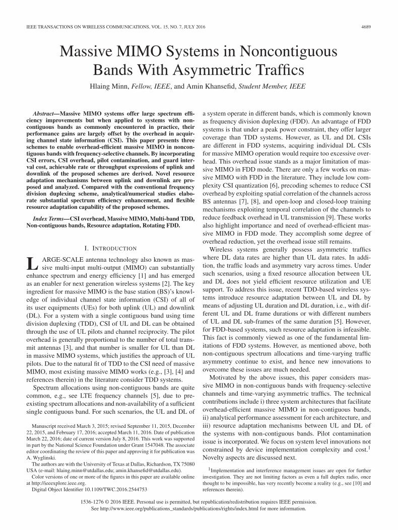
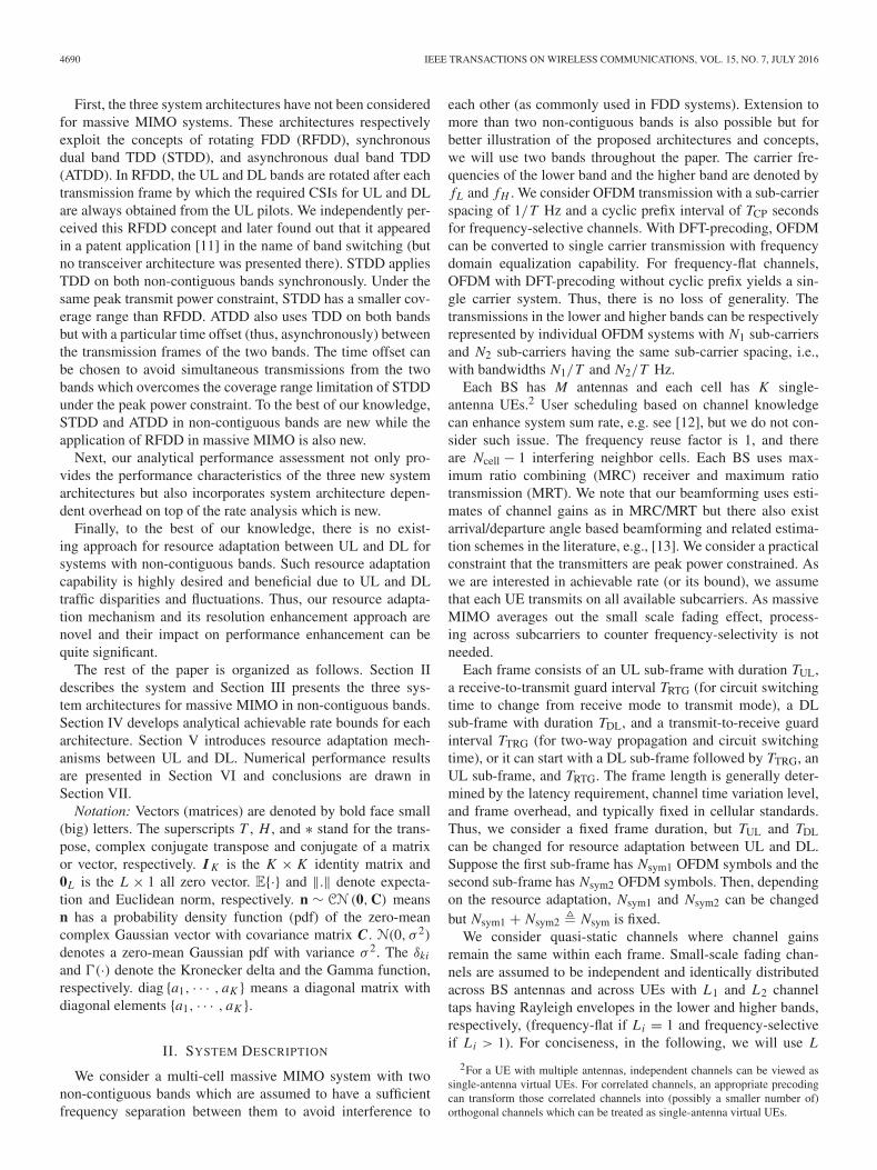
In this architecture, the UL band and the DL band arealternated in each transmission sub-frame, i.e., the carrier fre-quencies of the UL and DL bands are alternated or rotatedbetween fL and fH before the beginning of each transmissionsub-frame. The UL band in the current sub-frame becomes theDL band in the next sub-frame, so the CSI of the DL for thenext sub-frame can be obtained from the pilots in the currentUL sub-frame. This effectively solves the CSI overhead issueof massive MIMO in the conventional FDD scheme. Fig. 1presents the system architecture for a transceiver with RFDDwhere the difference from the conventional FDD architecture isthe adaptation/switching in the duplex filter and the frequencysynthesizer. Fig. 2 shows an example architecture for the adap-tive duplex filter which swaps the bandpass filters (BPFs) forthe transmit and receive signals through a switching circuit.Basically it has two modes where mode 1 receives in the higherband and transmits in the lower band while mode 2 receives inthe lower band and transmits in the higher band. The switchingcircuit facilitates changing between the two modes at the begin-ning of every sub-frame as instructed by the control signal. Anadaptive frequency synthesizer for RFDD is illustrated in Fig. 3where the transmit carrier frequency f1(t) and the receive car-rier frequency f2(t) are generated by a simple switching circuitand a dual output frequency synthesizer.
The transmit and receive timelines of RFDD in the two bandsare shown in Fig. 4 for BS and UEs. The BS timeline servesas the reference and is designed based on the target coveragerange or the UE at the cell edge (UEedge), while UE k with
MINN AND KHANSEFID: MASSIVE MIMO SYSTEMS IN NONCONTIGUOUS BANDS 4693
Fig. 2. An adaptive duplex filter (DF) architecture for RFDD.
Fig. 3. An adaptive frequency synthesizer for RFDD.
Fig. 4. Frame timeline for RFDD.
propagation delay τk adjusts its transmit and receive timelinesthrough synchronization (ranging [22]) to conform to the BSreference timeline. TUL,H and TDL,H represent the frame lengthsof UL and DL in the higher band, and TUL,L and TDL,L arethose in the lower band. For RFDD, we set TDL,H = TUL,L andTUL,H = TDL,L so that the transmissions from the two bands
Fig. 5. Transceiver system architecture for STDD.
Fig. 6. Frame timeline for STDD.
do not overlap and there is always some guard interval forswitching the bands.
B. Synchronous Dual Band TDD (STDD)
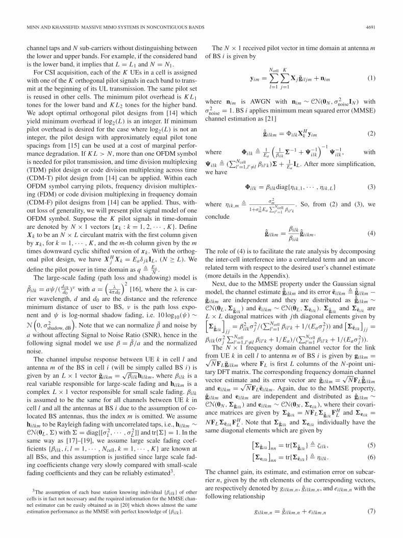
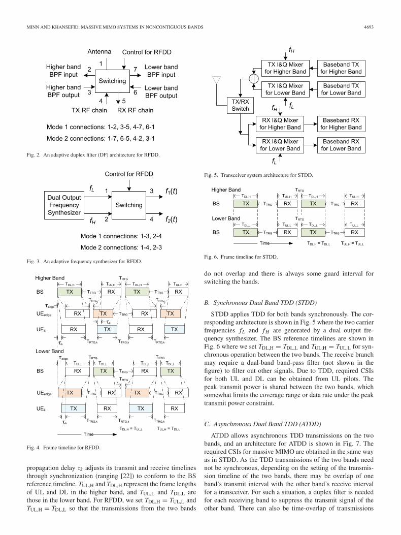
STDD applies TDD for both bands synchronously. The cor-responding architecture is shown in Fig. 5 where the two carrierfrequencies fL and fH are generated by a dual output fre-quency synthesizer. The BS reference timelines are shown inFig. 6 where we set TDL,H = TDL,L and TUL,H = TUL,L for syn-chronous operation between the two bands. The receive branchmay require a dual-band band-pass filter (not shown in thefigure) to filter out other signals. Due to TDD, required CSIsfor both UL and DL can be obtained from UL pilots. Thepeak transmit power is shared between the two bands, whichsomewhat limits the coverage range or data rate under the peaktransmit power constraint.
C. Asynchronous Dual Band TDD (ATDD)
ATDD allows asynchronous TDD transmissions on the twobands, and an architecture for ATDD is shown in Fig. 7. Therequired CSIs for massive MIMO are obtained in the same wayas in STDD. As the TDD transmissions of the two bands neednot be synchronous, depending on the setting of the transmis-sion timeline of the two bands, there may be overlap of oneband’s transmit interval with the other band’s receive intervalfor a transceiver. For such a situation, a duplex filter is neededfor each receiving band to suppress the transmit signal of theother band. There can also be time-overlap of transmissions

4694 IEEE TRANSACTIONS ON WIRELESS COMMUNICATIONS, VOL. 15, NO. 7, JULY 2016
Fig. 7. Transceiver system architecture for ATDD.
Fig. 8. Frame timeline for ATDD.
from the two bands during which coverage range or data ratewould be reduced under the peak transmit power constraint.ATDD’s transmission timeline can be set as in STDD (noduplex filter), as in RFDD (no rate sacrifice under peak powerconstraint), or between them depending on system requirements(e.g., UL and DL traffic loads as will be discussed in Section V).An example of the BS reference timeline without overlappedtransmissions (i.e., overcoming the peak power constraint issueof synchronous architecture) is shown in Fig. 8, for whichduplex filters are required.
The architecture in Fig. 7 is developed with adaptability forvarious scenarios in mind, thus it includes switches to bypassduplex filters when they are not needed (to avoid unnecessaryinsertion loss). If desired, the architecture can be simplified fora particular fixed scenario.
D. Characteristics Comparison
Here, we describe some key characteristics of the threearchitectures. RFDD needs an adaptive duplex filter. STDDexperiences more limited coverage range or data rate thanRFDD under the peak transmit power constraint. ATDD hasmost general transmission patterns (including those of RFDDand STDD), and may have similar coverage and data rate lim-itation of STDD when its transmission patterns follow STDD.ATDD offers more flexible resource adaptation than the othertwo, as will be discussed in a later section. The delays offeedback signaling (e.g., ARQ) in RFDD and ATDD can be
smaller than those in STDD since the transmission frames ofthe two bands in the former architectures are consecutive acrosstime except the guard intervals (see the figures of their frametimeline), so feedback can be sent on the earlier transmissionband of the two bands.
The proposed schemes are in general not limited to non-contiguous bands and could be applied to a single contiguousband by dividing it into two adjacent bands. In this case, STDDwill be the same as TDD with a single band, while RFDDand ATDD would need to handle i) self-interference at eachtransceiver as there will be significant leakage from the transmitchain to the receive chain and ii) intra-system multi-user inter-ference arisen from duplexing (unable to sufficiently suppresstransmit signal of other user at the receiver of a user). Thereexists a similar concept for a single contiguous band [23] whichconsiders multi-point to multi-point transmission, but due tothe above mentioned issues, the communication range is ratherlimited. Thus, although such extension of the proposed work istheoretically feasible, it will require substantial research whichis beyond the scope of this paper.
IV. PERFORMANCE ANALYSIS
We first present rate expressions, and then considering sys-tem overheads including pilots, cyclic prefix and guard inter-vals, we present throughput for different schemes.
A. Rate Expression
There exist several rate analyses of massive MIMO systems[17]–[19], [24]–[27] in the literature but for our considered sys-tems with multi-cell and pilot contamination, relevant worksare [26] which derives both UL and DL rates and [27] whichconcerns with DL rate only. However, both [26] and [27] con-sider frequency-flat channels and single band TDD systemswhile our system has frequency-selective channels and twonon-contiguous bands. We note that the DL rates in [27] and[26] are different due to differences in signal models (differentconstraints in precoding and different desired received signalterm). Our DL rate expression is adopted from our work in[27] by additionally incorporating frequency-selective chan-nels, their channel estimation MSEs which could be differentfor the two non-contiguous bands, and related CSI acquisitionoverhead. We also derive our UL rate expression but later findthat it can also be obtained from [26] although the approachesin derivation are different.
As discussed in Section II, for the considered system the sig-nal model is the same on each subcarrier. Thus, the sum rateover all the N subcarriers is N times the rate on a subcarrier.We will present the rate expressions per subcarrier in the fol-lowing. The lower bound of the achievable rate expression ona subcarrier for UL transmission is given by (11), shown at thebottom of the page, where pu is the UL transmit data power persubcarrier, and ζilk is the variance of the channel estimate on
Ruik,n = log2
⎛⎝1 + (M − 1)ζi ik
(M − 2)∑Ncell
l=1,l �=i ζilk + ∑Ncelll=1
∑Kj=1 βil j − ζi ik + 1
pu
⎞⎠ (11)

MINN AND KHANSEFID: MASSIVE MIMO SYSTEMS IN NONCONTIGUOUS BANDS 4695
the considered subcarrier which is given in (5). Although (11)can be obtained from [26], we obtain it by a different approachwhich could be beneficial for other research developments andhence our proof for (11) is briefly given in Appendix A.
The lower bound of the achievable rate on a subcarrier ofDL is given by (12), shown at the bottom of the page, where
c1(M) �(�(M+ 1
2 )
�(M)
)2
, and c2(M) � M − c1(M). Note that for
a large M , c2(M) ≈ 0.25 and c1(M) ≈ M [19]6. We observefrom the plot of c2(M) versus M that c2(M) monotonicallyincreases and saturates to 0.25 and it is well approximatedby 0.25 even at a medium value of M , e.g., c2(60) = 0.2495.Thus, the approximate expressions of c1(M) and c2(M) areaccurate for a moderate or large M . The power pd is the DLtransmit signal power per subcarrier per user. The proof for(12) can be obtained from [27] by replacing the statistics ofthe channel estimate of frequency-flat channels in [27] withthose of frequency-selective channels presented in (5), thus it isomitted.
B. System Throughput
In this section, considering DL and UL rate expressions aswell as overhead due to pilots, CP and guard intervals, we willpresent system throughputs. The UL pilot overhead is K L1tones for the lower band and K L2 tones for the upper band.The total guard interval is TG = TTRG + TRTG. The total time-frequency resource amount of the system for a combined ULsub-frame and DL sub-frame is W Ttot where W = 1
T (N1 + N2)
and Ttot = TG + Nsym1(T + TCP)+ Nsym2(T + TCP). We usea normalized throughput which is the achievable data rate ofthe considered link (UL, DL, or UL + DL) normalized byW Ttot. Such normalization is adopted due to two reasons. First,the sum of the normalized throughputs of UL and DL givesthe overall normalized throughput of the system (UL + DL).Second, they also serve as convenient metric values in resourceadaptation between UL and DL.
Let Ruik,L, Rd
ik,L, Ruik,H, and Ru
ik,H denote the UL and DLachievable rate on a subcarrier in the lower band and the higherband, respectively. Note that for frequency-flat channels therates in the two bands are equal, but for frequency-selectivechannels they can be different because of different channelestimation MSEs due to different numbers of channel taps.
First, we present the normalized throughputs of RFDD andSTDD. Their UL and DL normalized throughputs for UE k incell i are given by
ρu,RFDDik = (Nsym1 N1 − K L1)Ru
ik,L+(Nsym2 N2 − K L2)Ruik,H
(N1 + N2)(Nsym)+ (N1 + N2)(
TGT + TCP
T Nsym
)(13)
6c1(M) and c2(M) correspond to (E[θ ])2 and var(θ ) in [19].
Rdik,n = log2
⎛⎝1 + c1(M)ζi ik
(c2(M)− 1)ζi ik + K∑Ncell
l=1 βlik + (M − 1)∑Ncell
l=1,l �=i ζlik + 1pd
⎞⎠ (12)
ρd,RFDDik = (Nsym1 N2)Rd
ik,H + (Nsym2 N1)Rdik,L
(N1 + N2)(Nsym)+ (N1 + N2)(
TGT + TCP
T Nsym
)(14)
ρu,STDDik = (Nsym1 N1 − K L1)Ru
ik,L+(Nsym1 N2 − K L2)Ruik,H
(N1 + N2)(Nsym)+ (N1 + N2)(
TGT + TCP
T Nsym
)(15)
ρd,STDDik = (Nsym2 N1)Rd
ik,L + (Nsym2 N2)Rdik,H
(N1 + N2)(Nsym)+ (N1 + N2)(
TGT + TCP
T Nsym
) .(16)
Suppose the system has a constraint of maximum transmitpower per UE, i.e., E . Then, the transmit power per subcarrier isgiven by E
Nsimulwhere Nsimul is the number of subcarriers simul-
taneously used. For example for RFDD, data and pilot transmitpowers per subcarrier for UL and DL are q = pu = pd = E
N1in
the lower band and q = pu = pd = EN2
in the upper band. Butfor STDD, due to simultaneous transmissions in the two bands,pilot and data transmit powers per subcarrier for UL and DL aregiven by q = pu = pd = E
N1+N2.
Next, we present normalized throughputs for ATDD. Weassume the total numbers of OFDM symbols per frame in thelower and higher bands are the same and equal to Nsym. But thenumber of OFDM symbols for an UL sub-frame is Nsym,L1 inthe lower band and Nsym,H1 in the higher band. The correspond-ing numbers for a DL sub-frame are Nsym,L2 = Nsym − Nsym,L1and Nsym,H2 = Nsym − Nsym,H1. The two quantities Nsym,L1and Nsym,H1 can be set independently. An additional parame-ter to adjust for ATDD is the delay between the frame starts ofthe two bands. This delay influences the transmission overlapbetween the two bands which can affect the transmit powers ofthe two bands under a peak transmit power constraint.
As we mentioned before, under per-UE peak transmit powerconstraint, if there is time-overlap in transmissions in the twobands, the transmit power per subcarrier is reduced. Thus,depending on the parameter setting, ATDD may have two inter-vals with different subcarrier powers within a frame. To accountfor it, we introduce modified notations for the rate expressionsas Ru
ik,L(A, B), Rdik,L(A, B), Ru
ik,H(A, B) and Rdik,H(A, B)
where A and B represent pilot power per subcarrier and datapower per subcarrier, respectively.
We consider the scenario without UL transmission overlapbetween the two bands. The reason is that the UL transmis-sion overlap will reduce the UL pilot power, which will degradechannel estimation accuracy and both UL and DL rates. FromFig. 8, we obtain a general condition to avoid UL transmissionoverlap as TUL,H + TRTG ≤ TDL,L + TTRG or TUL,L + TRTG ≤TDL,H + TTRG. As can be observed in Fig. 8, the above condi-tion guarantees that each RX frame of BS (i.e., TX frame ofUE) in the higher band can be sandwiched between two RX
4696 IEEE TRANSACTIONS ON WIRELESS COMMUNICATIONS, VOL. 15, NO. 7, JULY 2016
frames of BS (i.e., TX frames of UE) in the lower band with-out any time-overlap while keeping circuit switching time Tcsfor transceiver mode change between between any two succes-sive TX frames of UE in different bands. With typical setting ofTRTG = Tcs and TTRG = 2τedge + Tcs, the condition can also beexpressed by dividing both sides with (T + TCP) as
Nsym,H1 ≤ Nsym,L2 +⌊
2τedge
T + TCP
⌋. (17)
OFDM systems typically have 2τedge < T + TCP, thus theabove condition reduces to Nsym,H1 ≤ Nsym,L2, i.e., the UL sub-frame length is not larger than the DL sub-frame length. Thesub-frame length condition is fortunately in line with typicalDL-dominated traffic loads. Next, the time offset between thetwo bands should be set to avoid UL transmission overlap.
Under UL transmission non-overlap case with a maximumtransmit power constraint, the normalized throughputs of ULand DL of ATDD are given by (18), (19) and (20), shown at thebottom of the page.
Similar to the throughput computation of RFDD, STDD andATDD, by incorporating pilot and guard interval overhead, wecan obtain the normalized throughputs of UL and DL of aconventional FDD scheme with massive MIMO as
ρu,FDDik = (Nsym N1 − M L2 − K L1)Ru
ik,L
(N1 + N2)(Nsym)(
1 + TCPT
) (21)
ρd,FDDik = (Nsym N2 − M L2)Rd
ik,H
(N1 + N2)(Nsym)(
1 + TCPT
) . (22)
The above FDD rates are substantially affected by the largepilot overhead due to the large number of BS antennas. Rd
ik,Hin the above is the same as that given in (12) as we assume per-fect feedback of the UEs’ DL MMSE channel estimates throughthe UL. However, for practical FDD systems, BS’s knowledgeof its DL channel would be degraded by additional errors inextracting DL channel estimates, thus its actual DL rate wouldbe worse than (12) and the above DL throughput represents anoptimistic result.
The total normalized throughput of the system (UL + DL) isgiven by
ρik = ρuik + ρd
ik (23)
ρu,ATDDik =
(Nsym,L1 N1 − K L1
)Ru
ik,L
(EN1, E
N1
)+ (
Nsym,H1 N2 − K L2)
Ruik,H
(EN1, E
N1
)
(N1 + N2)(Nsym
) + (N1 + N2)(
TGT + TCP
T Nsym
) (18)
ρd,ATDDik = Bik
(N1 + N2)(Nsym
) + (N1 + N2)(
TGT + TCP
T Nsym
) (19)
where
Bik �(Nsym,L1 N2
)Rd
ik,H
(E
N2,
E
N2
)+ (
Nsym,H2 − Nsym,L1)
N2 Rdik,H
(E
N1 + N2,
E
N2
)
+ (Nsym,H2 − Nsym,L1
)N1 Rd
ik,L
(E
N1 + N2,
E
N1
)+ (
Nsym,H1 N1)
Rdik,L
(E
N1,
E
N1
). (20)
where we use corresponding UL and DL throughput expres-sions of RFDD, STDD, ATDD or FDD to obtain the corre-sponding total normalized throughput.
The spectrum efficiency expression of each link (UL or DL)is given by the achievable rate normalized by the resourceamount of the considered individual link. If we split the guardtime overhead cost equally between UL and DL, the spectrumefficiency expressions for the UL and DL of RFDD, STDD andATDD are given as follows:
�u,RFDDik =
(Nsym1 N1 − K L1)Ruik,L + (Nsym2 N2 − K L2)Ru
ik,H
N1
(Nsym1
(1 + TCP
T
)+ TG
2
)+ N2
(Nsym2
(1 + TCP
T
)+ TG
2
)(24)
�d,RFDDik =
(Nsym1 N2)Rdik,H + (Nsym2 N1)Rd
ik,L
N2
(Nsym1
(1 + TCP
T
)+ TG
2
)+ N1
(Nsym2
(1 + TCP
T
)+ TG
2
)(25)
�u,STDDik =(Nsym1 N1 − K L1)Ru
ik,L + (Nsym1 N2 − K L2)Ruik,H
(N1 + N2)Nsym1 + (N1 + N2)(
TG2T + TCP
T Nsym1
) (26)
�d,STDDik =
(Nsym2 N1)Rdik,L + (Nsym2 N2)Rd
ik,H
(N1 + N2) Nsym2 + (N1 + N2)(
TG2T + TCP
T Nsym2
) (27)
�u,ATDDik =(Nsym,L1 N1 − K L1)Ru
ik,L + (Nsym,H1 N2 − K L2)Ruik,H
N1
(Nsym,L1
(1 + TCP
T
)+ TG
2
)+ N2
(Nsym,H1
(1 + TCP
T
)+ TG
2
)(28)
�d,ATDDik =
Bik
N1
(Nsym,L2
(1 + TCP
T
)+ TG
2
)+ N2
(Nsym,H2
(1 + TCP
T
)+ TG
2
) .(29)
Note that the spectrum efficiency of the overall system (UL +DL) is not necessarily the average of the UL and DL spectrum

MINN AND KHANSEFID: MASSIVE MIMO SYSTEMS IN NONCONTIGUOUS BANDS 4697
efficiencies, and a proper weighted average should be appliedespecially when the bandwidths of the two bands are different.On the other hand, the normalized throughput of the overallsystem given in (23) represents the spectrum efficiency of theoverall system.
V. RESOURCE ADAPTATION BETWEEN UPLINK
AND DOWNLINK
An important characteristic of a system is its capability ofresource adaptation between UL and DL since UL and DL traf-fic loads in practice are asymmetric and time-varying as well.For systems with non-contiguous bands, FDD is convention-ally applied but no resource adaptation mechanism is availablein the literature. Here, we present resource adaptation mecha-nisms for such systems by means of RFDD, STDD, and ATDDschemes. As presented earlier, the UL and DL throughputsdepend on the numbers of OFDM symbols in the UL and DLsubframes, i.e., Nsym1 and Nsym2 = Nsym − Nsym1. Thus, theadaptation is accomplished by changing them.
For RFDD, the time-frequency resource amounts (numbersof tones across time and frequency) allocated to UL and DL,respectively denoted by κu,RFDD and κd,RFDD, are given by
κu,RFDD = Nsym1 N1 + Nsym2 N2
= Nsym N2 + Nsym1(N1 − N2) (30)
κd,RFDD = Nsym(N1 + N2)− κu,RFDD
= Nsym N1 + Nsym1(N2 − N1). (31)
From (30) and (31), we can see that RFDD can performresource adaptation between UL and DL if N1 and N2 aredifferent or equivalently if the two bands have different band-widths.
The corresponding resource amounts for STDD are
κu,STDD = Nsym1(N1 + N2) (32)
κd,STDD = (Nsym − Nsym1)(N1 + N2) (33)
and those for ATDD are
κu,ATDD = Nsym,L1 N1 + Nsym,H1 N2 (34)
κd,ATDD = (Nsym − Nsym,L1)N1 + (Nsym − Nsym,H1)N2.
(35)
We can see from (30)–(35) that RFDD and STDD have oneparameter Nsym1 to adjust for resource adaptation, but ATDDhas two parameters Nsym,L1 and Nsym,H1 for adjustment. Thus,ATDD exhibits more flexible resource adaptation than theother two. However, if the system has a peak transmit powerconstraint, the ATDD’s adaptation should avoid some of theresource allocation settings with transmission overlap in thetwo bands which suffer substantial rate loss due to the trans-mit power sharing between simultaneous transmissions in thetwo bands. In the numerical result section, we will show resultsfor the case without UL transmission overlap.
As the adjustment parameters are discrete integers withincertain ranges, there are finite numbers of possible operation
points in resource adaptation. For RFDD and STDD, there areNsym − 1 operation points. For ATDD, by checking the numberof points of integer parameter pairs (Nsym,H1, Nsym,L2) sat-isfying the condition 1 ≤ Nsym,H1 ≤ Nsym,L2 ≤ N − 1 (fromthe sentence following (17) and the range of the parameters),we obtain 0.5Nsym(Nsym − 1) operation points. But as men-tioned before, the ATDD adaptation should exclude some pointswith substantial rate loss incurred by simultaneous transmis-sions from the bands. The selection of the operation points ofATDD for resource adaptation can easily be done by numericalevaluation of the throughput expressions.
As can be seen from (30)–(35), the bandwidths of the twobands (represented by N1 and N2) could also influence the oper-ation points or range of the resource adaptation. Thus, for futuresystems, the allocation/setting of the bandwidths of the twobands should also consider the targeted range of resource adap-tation so that the systems are more capable of handling trafficfluctuation and disparity between UL and DL.
The above numbers of operation points for RFDD, STDDand ATDD are reasonably sufficient for practical applications.If a finer granularity in resource adaptation is desired, wepropose to change the adjustment parameter(s) over a few suc-cessive frames. For convenience of presentation, first we defineoperation point as ratio of the amount of DL resources andthe amount of UL + DL resources, i.e. κu
κu+κd , over the con-sidered number of successive frames. For example, for RFDD,setting two different values of Nsym1, say (A1, A2), for everytwo successive frames, the operation points for adaptation aregiven by
κu,RFDD
κu,RFDD + κd,RFDD= Nsym N2 + A1+A2
2 (N1 − N2)
Nsym(N1 + N2)(36)
instead ofNsym N2+Ai (N1−N2)
Nsym(N1+N2). Then the adaptation resolution
of the operation point improves from (N1 − N2)/(Nsym(N1 +N2)) to 0.5(N1 − N2)/(Nsym(N1 + N2)). Similarly, for everyV successive frames, setting values of Nsym1 for the V framesto be (A1, A2, . . . , AV ) yields
κu,RFDD
κu,RFDD + κd,RFDD= Nsym N2 +
∑Vi=1 AiV (N1 − N2)
Nsym(N1 + N2), (37)
where κd,RFDD and κu,RFDD represent the total resourceamounts over V successive frames for DL and UL, respectively.Again, the operation point resolution for adaptation is improvedby a factor of V .
In multi-cell environments, not to cause additional intercellinterferences, adjacent cells should adopt the same resourceadaptation between UL and DL which can be determined bya mobile switching center which those cells are connected to.This practical constraint is the same as in TDD systems whereBSs synchronize to each other and apply the same resourceadaptation between UL and DL. For example, LTE specifi-cation defines several modes of resource adaptation in termsof sub-frame configurations for TDD. Note that such resourceadaptation is done based on medium-term traffic statistics (i.e.,at a much larger time scale than channel adaptation), and dueto similarity of traffic load patterns across cells, the UL and DL
4698 IEEE TRANSACTIONS ON WIRELESS COMMUNICATIONS, VOL. 15, NO. 7, JULY 2016
traffic load disparity is relatively similar across adjacent cells.Thus, even though individual cells would have different instan-taneous UL and DL traffic load disparities, the adaptation wouldstill offer overall improvement of system capacity. This aspectwill be illustrated in the next section.
VI. NUMERICAL RESULTS AND DISCUSSION
In this section, we present the massive MIMO performanceof RFDD, STDD, ATDD, and FDD in frequency-selectiveRayleigh fading channels with exponential power delay pro-file and 3 dB decay per tap. Most of the results are obtainedunder the peak transmit power constraint, but we also includea set of results without such constraint for completeness. Weassume pilots and data tones have the same power for eachscheme. Under the constraint of per-UE peak transmit powerE , RFDD and FDD have the transmit power per subcarrier ofE/N1 and E/N2 in the two bands. But STDD has the trans-mit power per subcarrier of E/(N1 + N2) in both of the bands.For ATDD, the transmit power per subcarrier is the same asSTDD (or RFDD) during the time with (or without) transmis-sion overlap between the two bands. When no peak transmitpower constraint is imposed, all schemes use the same transmitpower per subcarrier. We use a typical multicell structure withL = 7 cells and frequency reuse factor of 1. We assume theusers in each cell are uniformly located in the disk with radius1000 m around BS not closer than d0 = 100 m to BS, and thedistance of user k in cell l to BS i is denoted by dilk . So, {βilk}are independently generated by βilk = ψ/(
dilkd0)ν where ν =
3.8, 10 log10(ψ) ∼ N(
0, σ 2shadow, dB
)with σshadow, dB = 8. The
SNR is defined as SNR= p.E{βi ik }σ 2
noise, where p is transmit power
and the expectation is performed over shadow fading and userlocations. Under our simulation setting, E{βi ik} = −12.2 dB(which corresponds to E{βi ik} = −84.6 dB at 1 GHz). Thereare K = 10 UEs in each cell. The OFDM parameters are cho-sen to be consistent with LTE parameters, i.e., Nsym = 14,T = 1/15 (ms), TCP = 4.7 μs, and TG = 6.7 μs (based on theround-trip delay of a cell with radius 1000 m). Results areaveraged over 10,000 realizations of random large scale fadingcoefficients.
A. Performance Analysis
Here, we present the overall normalized system throughput(spectrum efficiency) given in (23) under the system settingof N1 = N2 = 128 subcarriers, L1 = L2 = 8 channel taps, thesame resource amount between UL and DL, Nsym1 = Nsym2 =7 symbols, and M = 60 BS antennas. Under the above set-ting, ATDD can have two settings ATTD1 and ATDD2 wheretheir transmission timelines are the same as that of RFDD andSTDD, respectively.7
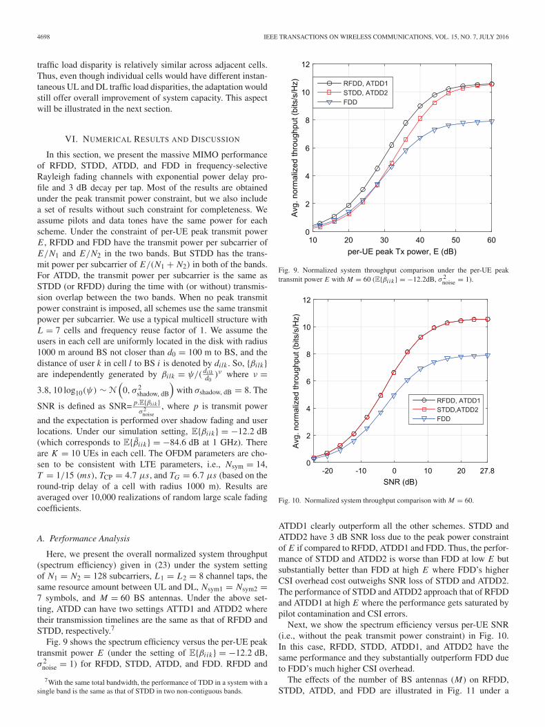
Fig. 9 shows the spectrum efficiency versus the per-UE peaktransmit power E (under the setting of E{βi ik} = −12.2 dB,σ 2
noise = 1) for RFDD, STDD, ATDD, and FDD. RFDD and
7With the same total bandwidth, the performance of TDD in a system with asingle band is the same as that of STDD in two non-contiguous bands.
Fig. 9. Normalized system throughput comparison under the per-UE peaktransmit power E with M = 60 (E{βi ik } = −12.2dB, σ 2
noise = 1).
Fig. 10. Normalized system throughput comparison with M = 60.
ATDD1 clearly outperform all the other schemes. STDD andATDD2 have 3 dB SNR loss due to the peak power constraintof E if compared to RFDD, ATDD1 and FDD. Thus, the perfor-mance of STDD and ATDD2 is worse than FDD at low E butsubstantially better than FDD at high E where FDD’s higherCSI overhead cost outweighs SNR loss of STDD and ATDD2.The performance of STDD and ATDD2 approach that of RFDDand ATDD1 at high E where the performance gets saturated bypilot contamination and CSI errors.
Next, we show the spectrum efficiency versus per-UE SNR(i.e., without the peak transmit power constraint) in Fig. 10.In this case, RFDD, STDD, ATDD1, and ATDD2 have thesame performance and they substantially outperform FDD dueto FDD’s much higher CSI overhead.
The effects of the number of BS antennas (M) on RFDD,STDD, ATDD, and FDD are illustrated in Fig. 11 under a
MINN AND KHANSEFID: MASSIVE MIMO SYSTEMS IN NONCONTIGUOUS BANDS 4699
Fig. 11. Effects of the number of BS antennas on the normalized systemthroughput (E = 30 dB, E{βi ik } = −12.2 dB, σ 2
noise = 1).
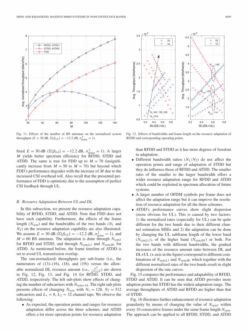
fixed E = 30 dB (E{βi ik} = −12.2 dB, σ 2noise = 1). A larger
M yields better spectrum efficiency for RFDD, STDD andATDD. The same is true for FDD up to M = 70 (insignifi-cantly increase from M = 50 to M = 70) but beyond whichFDD’s performance degrades with the increase of M due to theincreased CSI overhead toll. Also recall that the presented per-formance of FDD is optimistic due to the assumption of perfectCSI feedback through UL.
B. Resource Adaptation Between UL and DL
In this subsection, we present the resource adaptation capa-bility of RFDD, STDD, and ATDD. Note that FDD does nothave such capability. Furthermore, the effects of the framelength (Nsym) and the bandwidths of the two bands (N1 andN2) on the resource adaptation capability are also illustrated.We assume E = 30 dB (E{βi ik} = −12.2 dB, σ 2
noise = 1), andM = 60 BS antennas. The adaptation is done through Nsym1for RFDD and STDD, and through Nsym,L1 and Nsym,H1 forATDD. As mentioned before, the frame timeline of ATDD isset to avoid UL transmission overlap.
The (un-normalized) throughputs per sub-frame (i.e., thenumerators of (13)–(16), (18), and (19)) versus the allow-able normalized DL resource amount (i.e., κd
κu+κd ) are shownin Fig. 12, Fig. 13, and Fig. 14 for RFDD, STDD, andATDD, respectively. The left sub-plots show effects of chang-ing the number of subcarriers with Nsym=14. The right sub-plotspresents effects of changing Nsym with N1 = 128, N2 = 512subcarriers and L1 = 8, L2 = 32 channel taps. We observe thefollowing:
• As expected, the operation points and ranges for resourceadaptation differ across the three schemes, and ATDDoffers a lot more operation points for resource adaptation
Fig. 12. Effects of bandwidths and frame length on the resource adaptation ofRFDD and corresponding operating points.
than RFDD and STDD as it has more degrees of freedomin adaptation.
• Different bandwidth ratios (N1/N2) do not affect theoperation points and range of adaptation of STDD butthey do influence those of RFDD and ATDD. The smallerratio of the smaller to the larger bandwidth offers awider resource adaptation range for RFDD and ATDDwhich could be exploited in spectrum allocation of futuresystems.
• A larger number of OFDM symbols per frame does notaffect the adaptation range but it can improve the resolu-tion of resource adaptation for all the three schemes.
• ATDD’s performance curves show slight dispersion(more obvious for UL). This is caused by two factors:1) the normalized rates (especially for UL) can be quitedifferent for the two bands due to their different chan-nel estimation MSEs and 2) the adaptation can be doneby changing the UL subframe length of the lower band(Nsym,L1), of the higher band (Nsym,H1) or both. Forthe two bands with different bandwidths, the gradualincreases of the resource amount ratio between DL andDL+UL (x-axis in the figure) correspond to different com-binations of Nsym,L1 and Nsym,H1 which together with thedifferent normalized rates of the two bands result in slightdispersion of the rate curves.
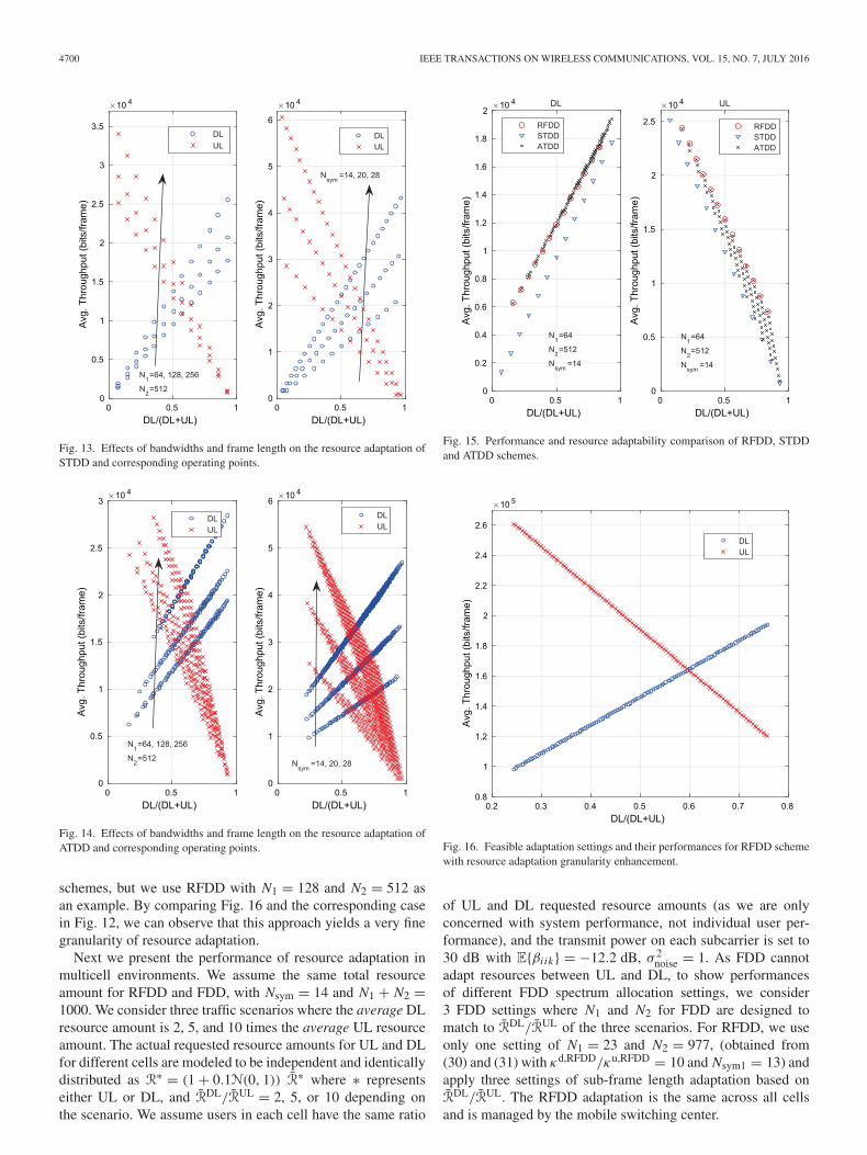
Fig. 15 compares the performance and adaptability of RFDD,STDD and ATDD. It can be seen that ATDD provides moreadaption points but STDD has the widest adaptation range. Theaverage throughputs of ATDD and RFDD are higher than thatof STDD.
Fig. 16 illustrates further enhancement of resource adaptationgranularity by means of changing the value of Nsym1 withinevery 10 consecutive frames under the same frame length Nsym.The approach can be applied to all RFDD, STDD, and ATDD
4700 IEEE TRANSACTIONS ON WIRELESS COMMUNICATIONS, VOL. 15, NO. 7, JULY 2016
Fig. 13. Effects of bandwidths and frame length on the resource adaptation ofSTDD and corresponding operating points.
Fig. 14. Effects of bandwidths and frame length on the resource adaptation ofATDD and corresponding operating points.
schemes, but we use RFDD with N1 = 128 and N2 = 512 asan example. By comparing Fig. 16 and the corresponding casein Fig. 12, we can observe that this approach yields a very finegranularity of resource adaptation.
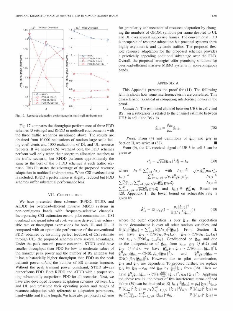
Next we present the performance of resource adaptation inmulticell environments. We assume the same total resourceamount for RFDD and FDD, with Nsym = 14 and N1 + N2 =1000. We consider three traffic scenarios where the average DLresource amount is 2, 5, and 10 times the average UL resourceamount. The actual requested resource amounts for UL and DLfor different cells are modeled to be independent and identicallydistributed as R∗ = (1 + 0.1N(0, 1)) R∗ where ∗ representseither UL or DL, and RDL/RUL = 2, 5, or 10 depending onthe scenario. We assume users in each cell have the same ratio
Fig. 15. Performance and resource adaptability comparison of RFDD, STDDand ATDD schemes.
Fig. 16. Feasible adaptation settings and their performances for RFDD schemewith resource adaptation granularity enhancement.
of UL and DL requested resource amounts (as we are onlyconcerned with system performance, not individual user per-formance), and the transmit power on each subcarrier is set to30 dB with E{βi ik} = −12.2 dB, σ 2
noise = 1. As FDD cannotadapt resources between UL and DL, to show performancesof different FDD spectrum allocation settings, we consider3 FDD settings where N1 and N2 for FDD are designed tomatch to RDL/RUL of the three scenarios. For RFDD, we useonly one setting of N1 = 23 and N2 = 977, (obtained from(30) and (31) with κd,RFDD/κu,RFDD = 10 and Nsym1 = 13) andapply three settings of sub-frame length adaptation based onRDL/RUL. The RFDD adaptation is the same across all cellsand is managed by the mobile switching center.
MINN AND KHANSEFID: MASSIVE MIMO SYSTEMS IN NONCONTIGUOUS BANDS 4701
Fig. 17. Resource adaptation performance in multi-cell environments.
Fig. 17 compares the throughput performance of three FDDschemes (3 settings) and RFDD in multicell environments withthe three traffic scenarios mentioned above. The results areobtained from 10,000 realizations of random large scale fad-ing coefficients and 1000 realizations of DL and UL resourcerequests. If we neglect CSI overhead cost, the FDD schemesperform well only when their spectrum allocation matches tothe traffic scenario, but RFDD performs approximately thesame as the best of the 3 FDD schemes at each traffic sce-nario. This illustrates the advantage of the proposed resourceadaptation in multicell environments. When CSI overhead costis included, RFDD’s performance is slightly reduced but FDDschemes suffer substantial performance loss.
VII. CONCLUSIONS
We have presented three schemes (RFDD, STDD, andATDD) for overhead-efficient massive MIMO systems innon-contiguous bands with frequency-selective channels.Incorporating CSI estimation errors, pilot contamination, CSIoverhead and guard interval cost, we have derived their achiev-able rate or throughput expressions for both UL and DL. Ifcompared with an optimistic performance of the conventionalFDD (obtained by assuming perfect feedback of CSI estimatethrough UL), the proposed schemes show several advantages.Under the peak transmit power constraint, STDD could havesmaller throughput than FDD for low to moderate values ofthe transmit peak power and the number of BS antennas butit has substantially higher throughput than FDD as the peaktransmit power or/and the number of BS antennas increase.Without the peak transmit power constraint, STDD alwaysoutperforms FDD. Both RFDD and ATDD with a proper set-ting substantially outperform FDD for all scenarios. Next, wehave also developed resource adaptation schemes between ULand DL and presented their operating points and ranges ofresource adaptation with reference to adaptation parameters,bandwidths and frame length. We have also proposed a scheme
for granularity enhancement of resource adaptation by chang-ing the numbers of OFDM symbols per frame devoted to ULand DL over several successive frames. The conventional FDDis incapable of resource adaptation but practical systems showhighly asymmetric and dynamic traffics. The proposed flex-ible resource adaptation for the proposed schemes providesa practically appealing additional advantage over the FDD.Overall, the proposed strategies offer promising solutions foroverhead-efficient massive MIMO systems in non-contiguousbands.
APPENDIX A
This Appendix presents the proof for (11). The followinglemma shows how some interference terms are correlated. Thischaracteristic is critical in computing interference power in theproof.
Lemma 1: The estimated channel between UE k in cell l andBS i on a subcarrier is related to the channel estimate betweenUE k in cell i and BS i as
gilk = βilk
βi ikgi ik . (38)
Proof: From (4) and definitions of gilk and gi ik inSection II, we arrive at (38). �
From (9), the UL received signal of UE k in cell i can begiven as
ruik = √
pu‖gi ik‖2suik + Iik (39)
where Iik �∑5
j=1 Iik, j with Iik,1 � √pugH
iikei iksuik ,
Iik,2 �∑K
j=1, j �=k√
pugHiikgi i j su
i j , Iik,3 �∑Ncelll=1,l �=i
∑Kj=1, j �=k
√pugH
iikgil j sul j , Iik,4 �∑K
j=1, j �=k√
pugHiikgilksu
lk and Iik,5 � gHiikni . Based on
[28, Appendix I], the lower bound on achievable rate isgiven by
Ruik = E{log2(1 + pu‖gi ik‖4
E{|Iik |2|gi ik} )} (40)
where the outer expectation is over gi ik , the expectationin the denominator is over all other random variables, andE{|Iik |2|gi ik} = ∑5
j=1 E{|Iik, j |2|gi ik}. From Section II,we have gilk ∼ CN(0M , βilkIM ), gilk ∼ CN(0M , ζilkIM )
and eilk ∼ CN(0M , ηilkIM ). Conditioned on gi ik and dueto the independence of gi ik from ei ik , gi i j ( j �= k) andgil j ( j �= k), we have gH
iikei ik |gi ik ∼ CN(0, ηi ik‖gi ik‖2),gH
iikgi i j |gi ik ∼ CN(0, βi i j‖gi ik‖2), and gHiikgil j |gi ik ∼
CN(0, βil j‖gi ik‖2). However, due to pilot contamination,gi ik and gilk are dependent. To proceed further, we replacegilk by gilk + eilk and gilk by βilk
βi ikgi ik from (38). Then we
have gHiikgilk |gi ik ∼ CN((
βilkβi ik
)‖gi ik‖2, ηilk‖gi ik‖2). Applyingthe above results, the power of five interference terms definedbelow (39) can be obtained as E{|Iik,1|2|gi ik} = pu‖gi ik‖2ηi ik ,E{|Iik,2|2|gi ik} = pu
∑Kj=1, j �=k ‖gi ik‖2βi i j , E{|Iik,3|2|gi ik} =
pu∑Ncell
l=1,l �=i
∑Kj=1, j �=k ‖gi ik‖2βil j , E{|Iik,4|2|gi ik} =

4702 IEEE TRANSACTIONS ON WIRELESS COMMUNICATIONS, VOL. 15, NO. 7, JULY 2016
pu∑K
j=1, j �=k(βilkβi ik)2‖gi ik‖4 + ηilk‖gi ik‖2, and E{|Iik,5|2|gi ik}
= ‖gi ik‖2. Then, we can write Ruik = E{log2(1 + 1
X )} where
X � 1‖gi ik‖2 (ηi ik + ∑K
j=1, j �=k βi i j +∑Ncelll=1,l �=i
∑Kj=1, j �=k βil j
+∑Ncelll=1,l �=i ηilk + 1
pu) +∑Ncell
l=1,l �=i (βilkβi ik)2. Next, with the
use of Jensen’s inequality for a convex function, i.e.,E{log2(1 + 1
X )} ≥ log2(1 + 1E{X} ), and the fact that 1
‖gi ik‖2 has
an inverse gamma distribution with E{ 1‖gi ik‖2 } = 1
(M−1)ζi ik, and
after some simplification using ζilk + ηilk = βilk , we arrive atthe lower bound on achievable rate Ru
ik as given in (11).
REFERENCES
[1] T. L. Marzetta, “Noncooperative cellular wireless with unlimited numbersof base station antennas,” IEEE Trans. Wireless Commun., vol. 9, no. 11,pp. 3590–3600, Nov. 2010.
[2] F. Boccardi, R. Heath, A. Lozano, T. Marzetta, and P. Popovski, “Fivedisruptive technology directions for 5G,” IEEE Commun. Mag., vol. 52,no. 2, pp. 74–80, Feb. 2014.
[3] F. Rusek et al., “Scaling up MIMO: Opportunities and challenges withvery large arrays,” IEEE Signal Process. Mag., vol. 30, no. 1, pp. 40–60,Jan. 2013.
[4] L. Lu, G. Li, A. Swindlehurst, A. Ashikhmin, and R. Zhang, “Anoverview of massive MIMO: Benefits and challenges,” IEEE J. Sel. TopicsSignal Process., vol. 8, no. 5, pp. 742–758, Oct. 2014.
[5] E. Dahlman, S. Parkvall, and J. Skold, 4G: LTE/LTE-Advanced forMobile Broadband. New York, NY, USA: Academic, 2013.
[6] J. Choi, Z. Chance, D. J. Love, and U. Madhow, “Noncoherent trelliscoded quantization: A practical limited feedback technique for massiveMIMO systems,” IEEE Trans. Commun., vol. 61, no. 12, pp. 5016–5029,Dec. 2013.
[7] A. Adhikary, J. Nam, J.-Y. Ahn, and G. Caire, “Joint spatial division andmultiplexing—The large-scale array regime,” IEEE Trans. Inf. Theory,vol. 59, no. 10, pp. 6441–6463, Oct. 2013.
[8] J. Chen and V. Lau, “Two-tier precoding for FDD multi-cell mas-sive MIMO time-varying interference networks,” IEEE J. Sel. AreasCommun., vol. 32, no. 6, pp. 1230–1238, Jun. 2014.
[9] J. Choi, D. Love, and P. Bidigare, “Downlink training techniques for FDDmassive MIMO systems: Open-loop and closed-loop training with mem-ory,” IEEE J. Sel. Topics Signal Process., vol. 8, no. 5, pp. 802–814, Oct.2013.
[10] A. K. Khandani, “Two-way (true full-duplex) wireless,” in Proc. 13thCan. Workshop Inf. Theory (CWIT), Jun. 2013, pp. 33–38.
[11] P. Bosch and S. Mullender, “Band switching for coherent beam formingin full-duplex wireless communication,” U.S. Patent 10 836 085, Nov. 3,2005.
[12] H. Liu, H. Gao, S. Yang, and T. Lv, “Low-complexity downlink userselection for massive MIMO systems,” IEEE Syst. J., 2015, submittedfor publication.
[13] A. Hu, T. Lv, H. Gao, Z. Zhang, and S. Yang, “An esprit-based approachfor 2-D localization of incoherently distributed sources in massive MIMOsystems,” IEEE J. Sel. Topics Signal Process., vol. 8, no. 5, pp. 996–1011,Oct. 2014.
[14] H. Minn and N. Al-Dhahir, “Optimal training signals for MIMO OFDMchannel estimation,” IEEE Trans. Wireless Commun., vol. 5, no. 5,pp. 1158–1168, May 2006.
[15] H. Minn and D. Munoz, “Channel knowledge acquisition in relayand multi-point to multi-point transmission systems,” IEEE Trans. Veh.Technol., vol. 64, no. 4, pp. 1416–1434, Apr. 2015.
[16] A. Goldsmith, Wireless Communications. Cambridge, U.K.: CambridgeUniv. Press, 2005.
[17] J. Hoydis, S. ten Brink, and M. Debbah, “Massive MIMO in the UL/DL ofcellular networks: How many antennas do we need?” IEEE J. Sel. AreasCommun., vol. 31, no. 2, pp. 160–171, Feb. 2013.
[18] H. Q. Ngo, E. G. Larsson, and T. L. Marzetta, “The multicell multiuserMIMO uplink with very large antenna arrays and a finite-dimensionalchannel,” IEEE Trans. Commun., vol. 61, no. 6, pp. 2350–2361, Jun.2013.
[19] J. Jose, A. Ashikhmin, T. L. Marzetta, and S. Vishwanath, “Pilot contam-ination and precoding in multi-cell TDD systems,” IEEE Trans. WirelessCommun., vol. 10, no. 8, pp. 2640–2651, Aug. 2011.
[20] A. Khansefid and H. Minn, “On channel estimation for massive MIMOwith pilot contamination,” IEEE Commun. Lett., vol. 19, no. 9, pp. 1660–1663, Sep. 2015.
[21] S. M. Kay, Fundamentals of Statistical Signal Processing, Volume I:Estimation Theory. Pearson Education, 1993, vol. 1.
[22] X. Fu, Y. Li, and H. Minn, “A new ranging method for OFDMA systems,”IEEE Trans. Wireless Commun., vol. 6, no. 2, pp. 659–669, Feb. 2007.
[23] W. Qiu, P. Tarasak, and H. Minn, “Orthogonal multicarrier division multi-ple access for multipoint-to-multipoint networks,” IEEE Trans. Commun.,vol. 61, no. 9, pp. 3841–3853, Sep. 2013.
[24] H. Q. Ngo, E. G. Larsson, and T. L. Marzetta, “Energy and spectral effi-ciency of very large multiuser MIMO systems,” IEEE Trans. Commun.,vol. 61, no. 4, pp. 1436–1449, Apr. 2013.
[25] H. Yang and T. L. Marzetta, “Performance of conjugate and zero-forcing beamforming in large-scale antenna systems,” IEEE J. Sel. AreasCommun., vol. 31, no. 2, pp. 172–179, Feb. 2013.
[26] H. Yang and T. L. Marzetta, “Capacity performance of multicell large-scale antenna systems,” in Proc. 51st Annu. Allerton Conf. Commun.Control Comput., Oct. 2013, pp. 668–675.
[27] A. Khansefid and H. Minn, “Achievable downlink rates of MRC and ZFprecoders in massive MIMO with uplink and downlink pilot contami-nation,” IEEE Trans. Commun., vol. 63, no. 12, pp. 4849–4864, Dec.2015.
[28] G. Caire, N. Jindal, M. Kobayashi, and N. Ravindran, “Multiuser MIMOachievable rates with downlink training and channel state feedback,”IEEE Trans. Inf. Theory, vol. 56, no. 6, pp. 2845–2866, Jun. 2010.
Hlaing Minn (S’99–M’01–SM’07–F’16) receivedthe B.E. degree in electrical engineering (electronics)from the Yangon Institute of Technology, Yangon,Myanmar, in 1995, the M.Eng. degree in telecom-munications from the Asian Institute of Technology,Pathumthani, Thailand, in 1997, and the Ph.D. degreein electrical engineering from the University ofVictoria, Victoria, BC, Canada, in 2001. DuringJanuary–August 2002, he was a Postdoctoral Fellowwith the University of Victoria. Since September2002, he has been with the Erik Jonsson School of
Engineering and Computer Science, University of Texas at Dallas, Richardson,TX, USA, where he is currently a Full Professor. His research interests includewireless communications, statistical signal processing, signal design, cross-layer design, cognitive radios, dynamic spectrum access and sharing, energyefficient wireless systems, next-generation wireless technologies, and wire-less healthcare applications. He is an Editor of the IEEE TRANSACTIONS ON
COMMUNICATIONS. He has served as a Technical Program Co-Chair for theWireless Communications Symposium of the IEEE Global CommunicationsConference (GLOBECOM 2014) and the Wireless Access Track of the IEEEVehicular Technology Conference (VTC, Fall 2009), as well as a TechnicalProgram Committee Member for several IEEE conferences.
Amin Khansefid (S’06) received the B.S. degreesin electrical engineering and mathematics, both fromIsfahan University of Technology, Isfahan, Iran, in2005, and the M.S. degree in electrical engineeringfrom the University of Tehran, Tehran, Iran, in 2008.He is currently pursuing the Ph.D. degree in electri-cal engineering at the University of Texas at Dallas,Richardson, TX, USA. He was an RF and ElectronicDesigner with Isfahan University of Technology from2008 to 2010, and a Research Associate with theDepartment of Electrical and Computer Engineering,
University of Tehran, Tehran, Iran, from 2010 to 2012. His research interestsinclude communication systems and signal processing.