marine high pressure carbon dioxide systems - ansul marine high... · u.s. coast guard approved...
TRANSCRIPT

MARINE HIGH PRESSURE CARBON DIOXIDE SYSTEMS
Component Sheet Library
One Stanton Street / Marinette, WI 54143-2542, USA / +1-715-735-7411 / www.ansul.comCopyright © 2015Tyco Fire Products LP. / All rights reserved. / Form No. PN76011-01 Component Sheets

TABLE OF CONTENTSU.S.C.G. APPROVAL NO. 162.038/7/0 REV. 1
UL EX 2968 6-12-12
TABLE OF CONTENTS
DESCRIPTION SECTION
EXPLANATION OF SAFETY ALERTS i
GENERAL INFORMATION 1
COMPONENT DESCRIPTION 2
SYSTEM DESIGN 3
SYSTEM INSTALLATION 4
RECHARGE AND MAINTENANCE 5
APPENDIX 6

COMPONENT DESCRIPTIONU.S.C.G. APPROVAL NO. 162.038/7/0 REV. 3
UL EX 2968 7-14-14 Page 2-1
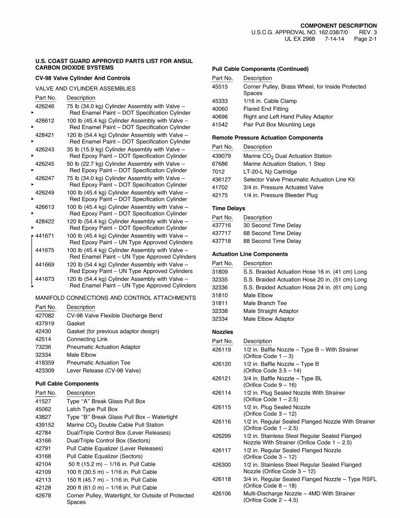
U.S. COAST GUARD APPROVED PARTS LIST FOR ANSUL CARBON DIOXIDE SYSTEMS
CV-98 Valve Cylinder And Controls
VALVE AND CYLINDER ASSEMBLIESPart No. Description426246 75 lb (34.0 kg) Cylinder Assembly with Valve – Red Enamel Paint – DOT Specification Cylinder426612 100 lb (45.4 kg) Cylinder Assembly with Valve – Red Enamel Paint – DOT Specification Cylinder428421 120 lb (54.4 kg) Cylinder Assembly with Valve –
Red Enamel Paint – DOT Specification Cylinder426243 35 lb (15.9 kg) Cylinder Assembly with Valve – Red Epoxy Paint – DOT Specification Cylinder426245 50 lb (22.7 kg) Cylinder Assembly with Valve – Red Epoxy Paint – DOT Specification Cylinder426247 75 lb (34.0 kg) Cylinder Assembly with Valve – Red Epoxy Paint – DOT Specification Cylinder426249 100 lb (45.4 kg) Cylinder Assembly with Valve –
Red Epoxy Paint – DOT Specification Cylinder426613 100 lb (45.4 kg) Cylinder Assembly with Valve – Red Epoxy Paint – DOT Specification Cylinder428422 120 lb (54.4 kg) Cylinder Assembly with Valve –
Red Epoxy Paint – DOT Specification Cylinder441671 100 lb (45.4 kg) Cylinder Assembly with Valve –
Red Epoxy Paint – UN Type Approved Cylinders441675 100 lb (45.4 kg) Cylinder Assembly with Valve –
Red Enamel Paint – UN Type Approved Cylinders441669 120 lb (54.4 kg) Cylinder Assembly with Valve –
Red Epoxy Paint – UN Type Approved Cylinders441673 120 lb (54.4 kg) Cylinder Assembly with Valve –
Red Enamel Paint – UN Type Approved Cylinders
MANIFOLD CONNECTIONS AND CONTROL ATTACHMENTSPart No. Description______ _________427082 CV-98 Valve Flexible Discharge Bend437919 Gasket42430 Gasket (for previous adaptor design)42514 Connecting Link73236 Pneumatic Actuation Adaptor32334 Male Elbow418359 Pneumatic Actuation Tee423309 Lever Release (CV-98 Valve)
Pull Cable ComponentsPart No. Description______ _________41527 Type‘‘A’’BreakGlassPullBox45062 Latch Type Pull Box43827 Type‘‘B’’BreakGlassPullBox–Watertight439152 Marine CO2 Double Cable Pull Station42784 Dual/Triple Control Box (Lever Releases)43166 Dual/Triple Control Box (Sectors)42791 Pull Cable Equalizer (Lever Releases)43168 Pull Cable Equalizer (Sectors)42104 50 ft (15.2 m) – 1/16 in. Pull Cable42109 100 ft (30.5 m) – 1/16 in. Pull Cable42113 150 ft (45.7 m) – 1/16 in. Pull Cable42128 200 ft (61.0 m) – 1/16 in. Pull Cable42678 CornerPulley,Watertight,forOutsideofProtected
Spaces
Pull Cable Components (Continued)Part No. Description45515 CornerPulley,BrassWheel,forInsideProtected
Spaces45333 1/16 in. Cable Clamp40060 Flared End Fitting40696 Right and Left Hand Pulley Adaptor41542 Pair Pull Box Mounting Legs
Remote Pressure Actuation ComponentsPart No. Description439079 Marine CO2 Dual Actuation Station67686 Marine Actuation Station, 1 Step7012 LT-20-L N2 Cartridge436127 Selector Valve Pneumatic Actuation Line Kit41702 3/4 in. Pressure Actuated Valve42175 1/4 in. Pressure Bleeder Plug
Time DelaysPart No. Description437716 30 Second Time Delay437717 68 Second Time Delay437718 88 Second Time Delay
Actuation Line ComponentsPart No. Description31809 S.S. Braided Actuation Hose 16 in. (41 cm) Long32335 S.S. Braided Actuation Hose 20 in. (51 cm) Long32336 S.S. Braided Actuation Hose 24 in. (61 cm) Long31810 Male Elbow31811 Male Branch Tee32338 Male Straight Adaptor32334 Male Elbow Adaptor
NozzlesPart No. Description426119 1/2in.BaffleNozzle–TypeB–WithStrainer (Orifice Code 1 – 3)426120 1/2 in. Baffle Nozzle – Type B (Orifice Code 3.5 – 14)426121 3/4 in. Baffle Nozzle – Type BL (Orifice Code 9 – 16)426114 1/2in.PlugSealedNozzleWithStrainer (Orifice Code 1 – 2.5)426115 1/2 in. Plug Sealed Nozzle (Orifice Code 3 – 12)426116 1/2in.RegularSealedFlangedNozzleWithStrainer
(Orifice Code 1 – 2.5)426299 1/2 in. Stainless Steel Regular Sealed Flanged
NozzleWithStrainer(OrificeCode1–2.5)426117 1/2 in. Regular Sealed Flanged Nozzle
(Orifice Code 3 – 12)426300 1/2 in. Stainless Steel Regular Sealed Flanged
Nozzle (Orifice Code 3 – 12)426118 3/4 in. Regular Sealed Flanged Nozzle – Type RSFL (Orifice Code 8 – 18)426106 Multi-DischargeNozzle–4MDWithStrainer (Orifice Code 2 – 4.5)
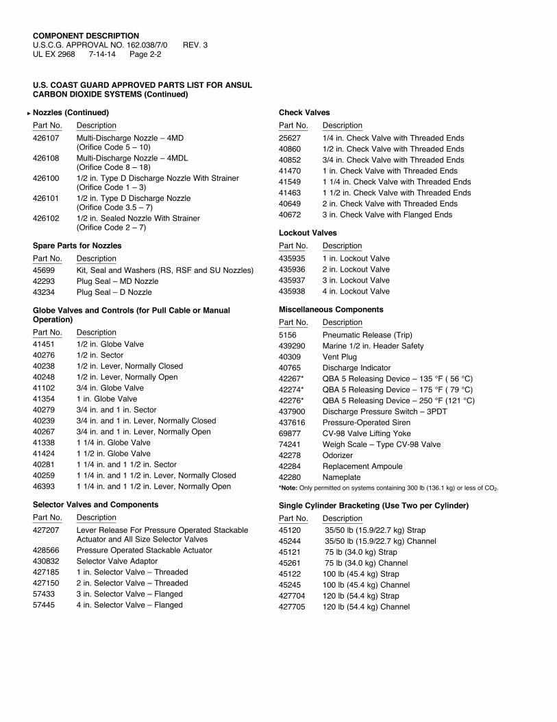
COMPONENT DESCRIPTIONU.S.C.G. APPROVAL NO. 162.038/7/0 REV. 3UL EX 2968 7-14-14 Page 2-2
U.S. COAST GUARD APPROVED PARTS LIST FOR ANSUL CARBON DIOXIDE SYSTEMS (Continued)
Nozzles (Continued)Part No. Description426107 Multi-Discharge Nozzle – 4MD (Orifice Code 5 – 10)426108 Multi-Discharge Nozzle – 4MDL (Orifice Code 8 – 18)426100 1/2in.TypeDDischargeNozzleWithStrainer (Orifice Code 1 – 3)426101 1/2 in. Type D Discharge Nozzle (Orifice Code 3.5 – 7)426102 1/2in.SealedNozzleWithStrainer (Orifice Code 2 – 7)
Spare Parts for NozzlesPart No. Description45699 Kit,SealandWashers(RS,RSFandSUNozzles)42293 Plug Seal – MD Nozzle43234 Plug Seal – D Nozzle
Globe Valves and Controls (for Pull Cable or Manual Operation)Part No. Description41451 1/2 in. Globe Valve40276 1/2 in. Sector40238 1/2 in. Lever, Normally Closed40248 1/2 in. Lever, Normally Open41102 3/4 in. Globe Valve41354 1 in. Globe Valve40279 3/4 in. and 1 in. Sector40239 3/4 in. and 1 in. Lever, Normally Closed40267 3/4 in. and 1 in. Lever, Normally Open41338 1 1/4 in. Globe Valve41424 1 1/2 in. Globe Valve40281 1 1/4 in. and 1 1/2 in. Sector40259 1 1/4 in. and 1 1/2 in. Lever, Normally Closed46393 1 1/4 in. and 1 1/2 in. Lever, Normally Open
Selector Valves and ComponentsPart No. Description427207 Lever Release For Pressure Operated Stackable
Actuator and All Size Selector Valves428566 Pressure Operated Stackable Actuator430832 Selector Valve Adaptor427185 1 in. Selector Valve – Threaded427150 2 in. Selector Valve – Threaded57433 3 in. Selector Valve – Flanged57445 4 in. Selector Valve – Flanged
Check ValvesPart No. Description25627 1/4 in. Check Valve with Threaded Ends40860 1/2 in. Check Valve with Threaded Ends40852 3/4 in. Check Valve with Threaded Ends41470 1 in. Check Valve with Threaded Ends41549 1 1/4 in. Check Valve with Threaded Ends41463 1 1/2 in. Check Valve with Threaded Ends40649 2 in. Check Valve with Threaded Ends40672 3 in. Check Valve with Flanged Ends
Lockout ValvesPart No. Description______ _________435935 1 in. Lockout Valve435936 2 in. Lockout Valve435937 3 in. Lockout Valve435938 4 in. Lockout Valve
Miscellaneous ComponentsPart No. Description5156 Pneumatic Release (Trip)439290 Marine 1/2 in. Header Safety40309 Vent Plug40765 Discharge Indicator42267* QBA 5 Releasing Device – 135 °F ( 56 °C)42274* QBA 5 Releasing Device – 175 °F ( 79 °C)42276* QBA 5 Releasing Device – 250 °F (121 °C)437900 Discharge Pressure Switch – 3PDT437616 Pressure-Operated Siren69877 CV-98 Valve Lifting Yoke74241 WeighScale–TypeCV-98Valve42278 Odorizer42284 Replacement Ampoule42280 Nameplate*Note: Only permitted on systems containing 300 lb (136.1 kg) or less of CO2.
Single Cylinder Bracketing (Use Two per Cylinder)Part No. Description45120 35/50 lb (15.9/22.7 kg) Strap45244 35/50 lb (15.9/22.7 kg) Channel45121 75 lb (34.0 kg) Strap45261 75 lb (34.0 kg) Channel45122 100 lb (45.4 kg) Strap45245 100 lb (45.4 kg) Channel427704 120 lb (54.4 kg) Strap427705 120 lb (54.4 kg) Channel
COMPONENT DESCRIPTIONU.S.C.G. APPROVAL NO. 162.038/7/0
UL EX 2968 1-19-09 Page 2-3
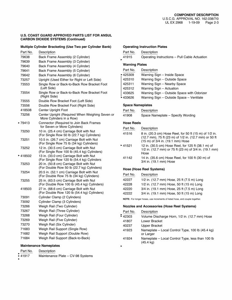
U.S. COAST GUARD APPROVED PARTS LIST FOR ANSUL CARBON DIOXIDE SYSTEMS (Continued)
Multiple Cylinder Bracketing (Use Two per Cylinder Bank)Part No. Description79638 Back Frame Assembly (2 Cylinder)79639 Back Frame Assembly (3 Cylinder)79640 Back Frame Assembly (4 Cylinder)79641 Back Frame Assembly (5 Cylinder)79642 Back Frame Assembly (6 Cylinder)73257 Upright (Used Either for Right or Left Side)73553 Single Row or Back-to-Back Row Bracket Foot
(Left Side)73554 Single Row or Back-to-Back Row Bracket Foot
(Right Side)73555 Double Row Bracket Foot (Left Side)73556 Double Row Bracket Foot (Right Side)418508 Center Upright Foot73256 CenterUpright(RequiredWhenWeighingSevenor
More Cylinders in a Row)79413 Connector (Required to Join Back Frames
for Seven or More Cylinders)73250 10 in. (25.4 cm) Carriage Bolt with Nut
(For Single Row 50 lb (22.7 kg) Cylinders)73251 10.5 in. (26.7 cm) Carriage Bolt with Nut
(For Single Row 75 lb (34 kg) Cylinders)73252 12 in. (30.5 cm) Carriage Bolt with Nut
(For Single Row 100 lb (45.4 kg) Cylinders)418502 13 in. (33.0 cm) Carriage Bolt with Nut
(For Single Row 120 lb (54.4 kg) Cylinders73253 20 in. (50.8 cm) Carriage Bolt with Nut
(For Double Row 50 lb (22.7 kg) Cylinders)73254 20.5 in. (52.1 cm) Carriage Bolt with Nut
(For Double Row 75 lb (34 kg) Cylinders)73255 25 in. (63.5 cm) Carriage Bolt with Nut
(For Double Row 100 lb (45.4 kg) Cylinders)418503 27 in. (68.6 cm) Carriage Bolt with Nut
(For Double Row 120 lb (54.4 kg) Cylinders)73091 Cylinder Clamp (2 Cylinders)73092 Cylinder Clamp (3 Cylinders)73266 WeighRail(TwoCylinder)73267 WeighRail(ThreeCylinder)73268 WeighRail(FourCylinder)73269 WeighRail(FiveCylinder)73270 WeighRail(SixCylinder)71683 WeighRailSupport(SingleRow)71682 WeighRailSupport(DoubleRow)71684 WeighRailSupport(Back-to-Back)
Maintenance NameplatesPart No. Description41917 Maintenance Plate – CV-98 Systems
Operating Instruction PlatesPart No. Description41915 Operating Instructions – Pull Cable Actuation
Warning PlatesPart No. Description425309 WarningSign–InsideSpace425310 WarningSign–OutsideSpace425311 WarningSign–NearbySpace425312 WarningSign–Actuation433625 WarningSign–OutsideSpacewithOdorizer433626 WarningSign–OutsideSpace–Ventilate
Space NameplatesPart No. Description41908 SpaceNameplate–SpecifyWording
Hose ReelsPart No. Description41516 8 in. (20.3 cm) Hose Reel, for 50 ft (15 m) of 1/2 in.
(12.7 mm), 75 ft (23 m) of 1/2 in. (12.7 mm) or 50 ft (15 m) of 3/4 in. (19.1 mm) Hose
41521 12 in. (30.5 cm) Hose Reel, for 125 ft (38.1 m) of 1/2 in. (12.7 mm) or 75 ft (23 m) of 3/4 in. (19.1 mm) Hose
41142 14 in. (35.6 cm) Hose Reel, for 100 ft (30 m) of 3/4 in. (19.1 mm) Hose
Hose (Hose Reel Systems)Part No. Description42227 1/2 in. (12.7 mm) Hose, 25 ft (7.5 m) Long42228 1/2 in. (12.7 mm) Hose, 50 ft (15 m) Long42220 3/4 in. (19.1 mm) Hose, 25 ft (7.5 m) Long42222 3/4 in. (19.1 mm) Hose, 50 ft (15 m) LongNOTE: For longer hoses, use increments of listed hose, and couple together.
Nozzles and Accessories (Hose Reel Systems)Part No. Description42303 Volume Discharge Horn, 1/2 in. (12.7 mm) Hose41807 Lower Bracket40237 Upper Bracket41923 Nameplate – Local Control Type, 100 lb (45.4 kg)
or Larger41924 Nameplate – Local Control Type, less than 100 lb
(45.4 kg)

COMPONENT DESCRIPTIONU.S.C.G. APPROVAL NO. 162.038/7/0 REV. 2UL EX 2968 7-14-14 Page 2-4
CV-98 CYLINDER SHIPPING ASSEMBLYThe CV-98 cylinder is factory filled with carbon dioxide. A single cylin-der may be used or multiple cylinders can be manifolded together to obtain the required quantity of agent for total flooding or local applica-tion methods. The CV-98 cylinder valve can be actuated pneumatically and/or manually with approved valve actuation components.CV-98cylindervalvesare“backpressure”operated.Whenconnectedto a discharge manifold with approved flexible discharge hoses, slave operated CV-98 cylinder valves will be opened by CO2 back pressure in the manifold.The cylinders are shipped with a maintenance record card and protec-tive shipping cap attached to the threaded neck of each cylinder. This cap entirely encloses and protects the valve while in shipment.The 35 and 50 lb (15.9 and 22.7 kg) cylinders are manufactured with a bent siphon tube which allows for either horizontal or vertical mount-ing.Whenmountinghorizontally,valveoutletmustbehorizontal,andsafety disk nut must be in “up” position.The valve requires no internal maintenance. The valve is sealed closed and must never be disassembled. If there is ever a malfunction of the CV-98 valve, the complete valve must be sent back to Tyco Fire Protection Products.Material: Cylinder – Steel CV-98 Valve – Brass Safety Relief Valve – Brass Shipping Cap – SteelShipping Weight ApproximateAssembly of CO2 Weight DimensionA DimensionBPart No. lb (kg) lb (kg) in. (mm) in. (mm)
Finish: Red Enamel Paint426246 (DOT/TC) 75 (34.0) 200 (91) 57 3/4 (1467) 9 1/4 (235)426612* (DOT/TC) 100 (45.4) 300 (136) 60 1/4 (1530) 10 1/2 (267)441675 (UN) 100 (45.4) 300 (136) 60 1/4 (1530) 10 1/2 (267)428421* (DOT/TC) 120 (54.4) 390 (177) 66 5/8 (1692) 11 (279)441673 (UN) 120 (54.4) 390 (177) 66 5/8 (1692) 11 (279)Finish: Red Epoxy Paint426243 (DOT/TC) 35 (15.9) 121 (55) 35 3/4 (908) 8 1/2 (216)426245 (DOT/TC) 50 (22.7) 165 (75) 52 3/4 (1340) 8 1/2 (216)426247 (DOT/TC) 75 (34.0) 200 (91) 57 3/4 (1467) 9 1/4 (235)426249* (DOT/TC) 100 (45.4) 300 (136) 59 3/4 (1517) 10 3/4 (273)426613* (DOT/TC) 100 (45.4) 300 (136) 60 1/4 (1530) 10 1/2 (267)441671 (UN) 100 (45.4) 300 (136) 60 1/4 (1530) 10 1/2 (267)428422* (DOT/TC) 120 (54.4) 390 (177) 66 5/8 (1692) 11 (279)441669 (UN) 120 (54.4) 390 (177) 66 5/8 (1692) 11 (279)* These containers are special order: minimum order quantities apply, please call for delivery time.
FIGURE 2-1
BDIAMETER
SIPHON TUBE
RECORD TAG
SIPHON TUBE ADAPTOR
CYLINDER SHIPPING CAP(PART NO. 73066)
CV-98 VALVE
VALVE SHIPPING CAP
001416
AHEIGHT
TO OUTLET
NOTE: USE FLEXIBLE DISCHARGE BEND, PART NO. 427082, WHENATTACHINGVALVETOSUPPLYPIPEORMANIFOLD.
SAFETY RELIEF DISC (BURST PRESSURE 2700-3000 PSI, TESTED PER CGA S-1.1)
FILL PORT (MATESWITHFILL ADAPTOR, PART NO. 423659
DISCHARGE BEND OUTLETWITHRECOILVALVE(MATESWITH FLEXIBLE DISCHARGE BEND, PART NO. 427082)
1.125-18 THREADED FOR RELEASE ATTACHMENTS OR SHIPPING CAP
001816
COMPONENT DESCRIPTIONU.S.C.G. APPROVAL NO. 162.038/7/0 REV. 1
UL EX 2968 3-20-12 Page 2-5
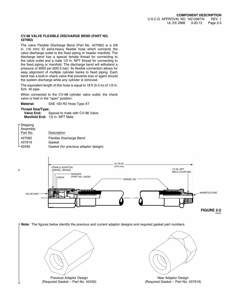
CV-98 VALVE FLEXIBLE DISCHARGE BEND (PART NO. 427082)The valve Flexible Discharge Bend (Part No. 427082) is a 5/8 in. (16 mm) ID extra-heavy flexible hose which connects the valve discharge outlet to the fixed piping or header manifold. The discharge bend has a special female thread for connecting to the valve outlet and a male 1/2 in. NPT thread for connecting to the fixed piping or manifold. The discharge bend will withstand a pressure of 9000 psi (620.5 bar). Its flexible connection allows for easy alignment of multiple cylinder banks to fixed piping. Each bend has a built-in check valve that prevents loss of agent should the system discharge while any cylinder is removed.The equivalent length of this hose is equal to 18 ft (5.5 m) of 1/2 in. Sch. 40 pipe.When connected to the CV-98 cylinder valve outlet, the checkvalve is held in the “open” position.Material: SAE 100 R2 Hose Type ATThread Size/Type: Valve End: Special to mate with CV-98 Valve Manifold End: 1/2 in. NPT Male
ShippingAssemblyPart No. Description427082 Flexible Discharge Bend437919 Gasket42430 Gasket (for previous adaptor design)
FIGURE 2-2000658
18 7/8 IN.(479 mm)
MANIFOLD END
1/2 IN. NPTMALE COUPLING
FEMALE ADAPTOR (SWIVEL,BRASS)
VALVE END
CHECKSWAGEON
WASHER(PART NO. 42430)
Previous Adaptor Design (Required Gasket – Part No. 42430)
New Adaptor Design (Required Gasket – Part No. 437919)
Note: The figures below identify the previous and current adaptor designs and required gasket part numbers.

COMPONENT DESCRIPTIONU.S.C.G. APPROVAL NO. 162.038/7/0UL EX 2968 1-19-09 Page 2-6
CONNECTING LINK (PART NO. 42514)Material: SteelThe connecting link is used to connect the lever releases located on the pilot cylinders, employing the CV-98 valve.An opening in the end of the connecting link allows connection of the wire rope for pull-cable actuated systems.
FIGURE 2-3007978
PIVOT PINHANDLE
OPENING FOR PULL-CABLE LOOP
3/4 IN. (19 mm)
15/16 IN. (24 mm)
HEX NUT
14 1/4 IN.(36.2 cm)

COMPONENT DESCRIPTIONU.S.C.G. APPROVAL NO. 162.038/7/0 REV. 1
UL EX 2968 6-12-12 Page 2-7
CV-98 VALVE PNEUMATIC ACTUATIONThe CV-98 valve has a built-in pneumatic actuation port for use with the Marine Actuation Station or the Quartzoid Bulb Actuator. Use the adaptor, elbow, and tee to connect the pilot cylinders to the actuation station or to the Quartzoid Bulb Actuator. A minimum pressure of 100 psi (6.9 bar) is required to actuate the valve.Material: SteelPart No. Description73236 Adaptor32334 Male Elbow418359 Tee
Note: Actuation piping must be vented.
FIGURE 2-4004486
TEE (PART NO.418359) (TYP.)
16 IN. STAINLESS STEEL HOSE (PART NO. 31809) (TYP.)
TO MARINE ACTU-ATION STATION OR TO QUARTZOID BULB ACTUATOR FOR “CYLINDER RELEASE”
MALEELBOW(PART NO. 32334) (TYP.)
ADAPTOR(PART NO. 73236) (TYP.)
1/4 IN. CHECK VALVE (PART NO. 25627)STRAIGHT ADAPTOR
(PART NO. 32338)ORELBOW(PARTNO. 31810)
1/4 IN. NIPPLE BY INSTALLER
PRESSURE BLEEDER PLUG (PART NO. 42175)

COMPONENT DESCRIPTIONU.S.C.G. APPROVAL NO. 162.038/7/0UL EX 2968 1-19-09 Page 2-8
SELECTOR/ISOLATION VALVE PNEUMATIC ACTUATIONThe selector valves and 3/4 in. isolation valve can be pneumati-cally actuated by the Marine Actuation Station. Use the Selector Valve Pneumatic Actuation Line Kit to control the pressure in the actuation line. One Selector Valve Pneumatic Actuation Line Kit is required for each pneumatic actuator and must be installed within 1 ft (0.3 m) of the pneumatic actuator/isolation valve. The Low Pressure Vent Plug and Safety Relief Valve are to be installed with a torque of 125 in.-lb (14 Nm). After system discharge, all pressure in the actuation line must be relieved by pulling the ring on the safety relief valve.
Part No. Description428566 Pressure Operated Stackable Actuator*41702 3/4 in. Pressure Operated Isolation Valve436127 Selector Valve Pneumatic Actuation Line Kit
(Kit includes Low Pressure Vent Plug, Part No. 436085, Safety Relief Valve, Part No. 15677, 1/4 in. Close Nipple, Part No. 28484, and 1/4 in. Tee, Part No. 27350)
*Note: The Pressure Operated Stackable Actuator is only required on selector valves.
008204
PRESSURE OPERATED STACKABLE ACTUATOR (PART NO. 428566)
1 IN., 2 IN., 3 IN., OR 4 IN. SELECTOR VALVE (4IN.SHOWN)
TO MARINE ACTUATION STATIONFOR‘VALVERELEASE’
FIGURE 2-5
SELECTOR VALVE PNEUMATIC ACTUATION LINE KIT (PART NO. 436127)
FIGURE 2-5a008334
SELECTOR VALVE PNEUMATIC ACTUATION LINE KIT (PART NO. 436127)
3/4 IN. PRESSURE ACTUATED ISOLATION VALVE (PART NO. 41702)
TO MARINE ACTUATION STATION

COMPONENT DESCRIPTIONU.S.C.G. APPROVAL NO. 162.038/7/0
UL EX 2968 1-19-09 Page 2-9
BAFFLE NOZZLE – TYPE B – WITH STRAINER (PART NO. 426119*)The baffle type nozzle with strainer is used in total flooding applications only. Placed around the outside edge or placed near the overhead approximately 15 to 20 ft (4.6 to 6.1 m) on centers in a room or any enclosed space, each nozzle provides a 180° fan spray of carbon dioxide, spreading the extinguishing gas quickly and efficiently throughout the protected space.Discharge rate depends upon nozzle pressure and orifice size. Baffle type nozzles with strainer are available in orifice sizes 1 through 3. This nozzle is supplied in natural brass. Material: Nozzle – Brass Strainer – MonelNote: Whenordering,specifyorificecoderequired:
Example – Part No. 426119 – 1.5 (See Baffle Nozzle Orifice Code Selection Chart in Appendix section).
* Nozzle previously supplied under Part No. 44790-44794.
FIGURE 2-6000662
1 3/4 IN.(44 mm)
1/2 IN. NPT
STRAINER
FORGED BRASS BODY
DISCHARGE ORIFICE
ORIFICE SIZE STAMPED ON THIS SURFACE
2 5/8 IN.(67 mm)

COMPONENT DESCRIPTIONU.S.C.G. APPROVAL NO. 162.038/7/0UL EX 2968 1-19-09 Page 2-10
BAFFLE NOZZLE – TYPE B (PART NO. 426120*)The baffle type B nozzle is used in total flooding applications only. Placed around the outside edge or placed near the over-head approximately 15 to 20 ft (4.6 to 6.1 m) on centers in a room or any enclosed space, each nozzle provides a 180° fan spray of carbon dioxide, spreading the extinguishing gas quickly and efficiently throughout the protected space.Discharge rate depends upon nozzle pressure and orifice size. Baffle type B nozzles are available in orifice sizes 3.5 through 14. This nozzle is supplied in natural brass. Material: BrassNote: Whenordering,specifyorificecoderequired:
Example – Part No. 426120 – 3.5 (See Baffle Nozzle Orifice Code Selection Chart in Appendix section).
* Nozzle previously supplied under Part No. 44629-44650.
FIGURE 2-7000663
1 3/4 IN.(44 mm)
1/2 IN. NPT
FORGED BRASS BODY
DISCHARGE ORIFICE
ORIFICE SIZE STAMPED ON THIS SURFACE
2 5/8 IN.(67 mm)

COMPONENT DESCRIPTIONU.S.C.G. APPROVAL NO. 162.038/7/0UL EX 2968 1-19-09 Page 2-11
BAFFLE NOZZLE – TYPE BL (PART NO. 426121*)The baffle type BL nozzle is used in total flooding applications only. Placed around the outside edge or placed near the over-head approximately 15 to 20 ft (4.6 to 6.1 m) on centers in a room or any enclosed space, each nozzle provides a 180° fan spray of carbon dioxide, spreading the extinguishing gas quickly and efficiently throughout the protected space.Discharge rate depends upon nozzle pressure and orifice size. Baffle type BL nozzles are available in orifice sizes 9 through 16. This nozzle is supplied in natural brass. Material: BrassNote: Whenordering,specifyorificecoderequired:
Example – Part No. 426121 – 10.5 (See Baffle Nozzle Orifice Code Selection Chart in Appendix section).
* Nozzle previously supplied under Part No. 44952-44966.
FIGURE 2-8000664
2 1/4 IN.(57 mm)
3/4 IN. NPT
FORGED BRASS BODY
DISCHARGE ORIFICE
STAMPED NOZZLE CODE
3 5/16 IN.(84 mm)
3 1/4 IN.(83 mm)
COMPONENT DESCRIPTIONU.S.C.G. APPROVAL NO. 162.038/7/0UL EX 2968 1-19-09 Page 2-12
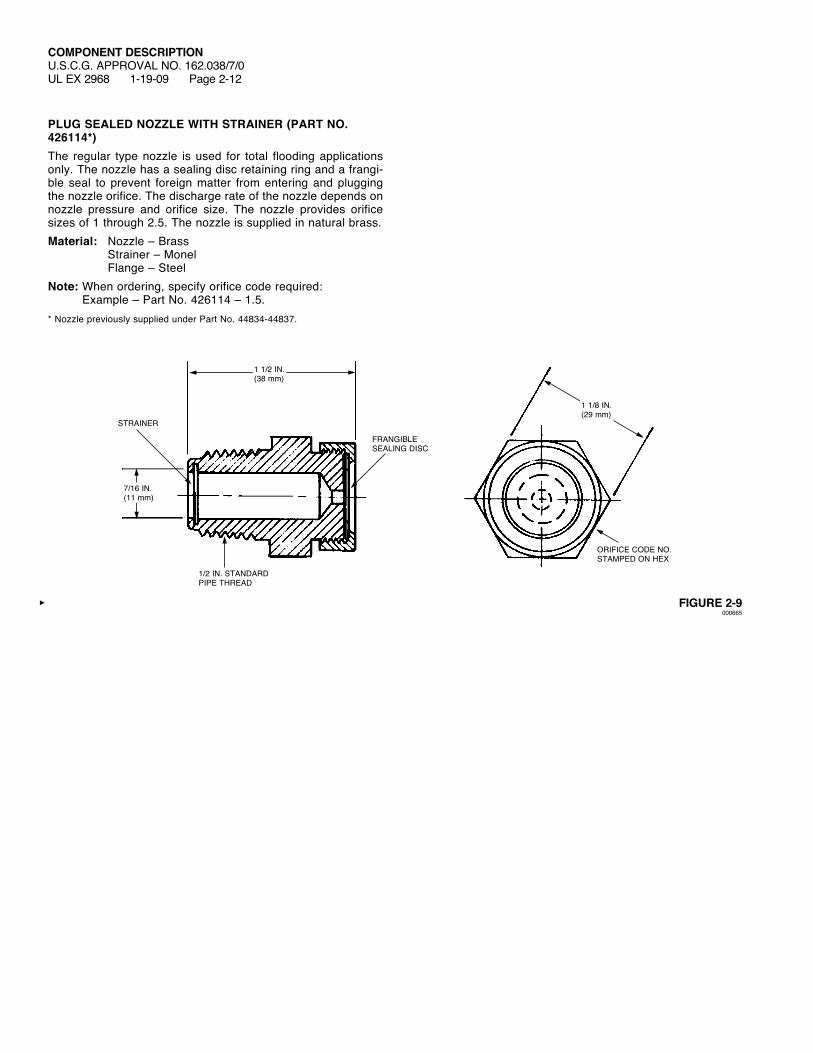
PLUG SEALED NOZZLE WITH STRAINER (PART NO. 426114*)The regular type nozzle is used for total flooding applications only. The nozzle has a sealing disc retaining ring and a frangi-ble seal to prevent foreign matter from entering and plugging the nozzle orifice. The discharge rate of the nozzle depends on nozzle pressure and orifice size. The nozzle provides orifice sizes of 1 through 2.5. The nozzle is supplied in natural brass.Material: Nozzle – Brass Strainer – Monel Flange – SteelNote: Whenordering,specifyorificecoderequired:
Example – Part No. 426114 – 1.5.* Nozzle previously supplied under Part No. 44834-44837.
FIGURE 2-9000665
7/16 IN.(11 mm)
1 1/2 IN.(38 mm)
STRAINER
1/2 IN. STANDARDPIPE THREAD
FRANGIBLE SEALING DISC
ORIFICE CODE NO.STAMPED ON HEX
1 1/8 IN.(29 mm)

COMPONENT DESCRIPTIONU.S.C.G. APPROVAL NO. 162.038/7/0UL EX 2968 1-19-09 Page 2-13
PLUG SEALED NOZZLE (PART NO. 426115*)The regular type nozzle is used for total flooding applications only. The discharge rate of the nozzle depends on nozzle pressure and orifice size. The nozzle provides orifice sizes of 3 through 12. The nozzle is supplied in natural brass.Material: Nozzle – Brass Flange – SteelNote: Whenordering,specifyorificecoderequired:
Example – Part No. 426115 – 4.5.* Nozzle previously supplied under Part No. 44838-44856.
FIGURE 2-10000666
7/16 IN.(11 mm)
1 1/2 IN.(38 mm)
1/2 IN. STANDARDPIPE THREAD
FRANGIBLE SEALING DISC
ORIFICE CODE NO.STAMPED ON HEX
1 1/8 IN.(29 mm)

COMPONENT DESCRIPTIONU.S.C.G. APPROVAL NO. 162.038/7/0UL EX 2968 1-19-09 Page 2-14
REGULAR SEALED FLANGED NOZZLE WITH STRAINER (PART NO. 426116* and 426299)The regular type nozzle is used for total flooding applications only. The nozzle has a sealing disc retaining ring and a frangi-ble seal to prevent foreign matter from entering and plugging the nozzle orifice. The discharge rate of the nozzle depends on nozzle pressure and orifice size. The nozzle provides orifice sizes of 1 through 2.5. The nozzle is supplied in natural brass (Part No. 426116) or stainless steel (Part No. 426299).Material: Nozzle – Brass Strainer – Monel Flange – SteelNote: Whenordering,specifyorificecoderequired:
Example – Part No. 426116 – 1.5.* Nozzle previously supplied under Part No. 44857-44860.
FIGURE 2-11000667
3/16 IN. (4.8 mm) MOUNTING HOLE
SELF-TAPPINGSCREW
SEAL
STRAINER
1/2 IN. NPT
3 IN.(76 mm)
2 1/2 IN.(64 mm)
1 5/8 IN.(41 mm)
2 1/2 IN.(64 mm)
3 IN.(76 mm)
1 IN.CLEARANCE HOLE
COMPONENT DESCRIPTIONU.S.C.G. APPROVAL NO. 162.038/7/0UL EX 2968 1-19-09 Page 2-15
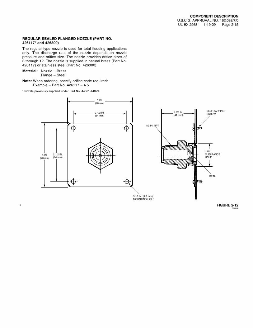
REGULAR SEALED FLANGED NOZZLE (PART NO. 426117* and 426300)The regular type nozzle is used for total flooding applications only. The discharge rate of the nozzle depends on nozzle pressure and orifice size. The nozzle provides orifice sizes of 3 through 12. The nozzle is supplied in natural brass (Part No. 426117) or stainless steel (Part No. 426300).Material: Nozzle – Brass Flange – SteelNote: Whenordering,specifyorificecoderequired:
Example – Part No. 426117 – 4.5.* Nozzle previously supplied under Part No. 44861-44879.
FIGURE 2-12000668
3/16 IN. (4.8 mm) MOUNTING HOLE
SELF-TAPPINGSCREW
SEAL
1/2 IN. NPT
3 IN.(76 mm)
2 1/2 IN.(64 mm)
1 5/8 IN.(41 mm)
2 1/2 IN.(64 mm)
3 IN.(76 mm)
1 IN.CLEARANCE HOLE
COMPONENT DESCRIPTIONU.S.C.G. APPROVAL NO. 162.038/7/0UL EX 2968 1-19-09 Page 2-16
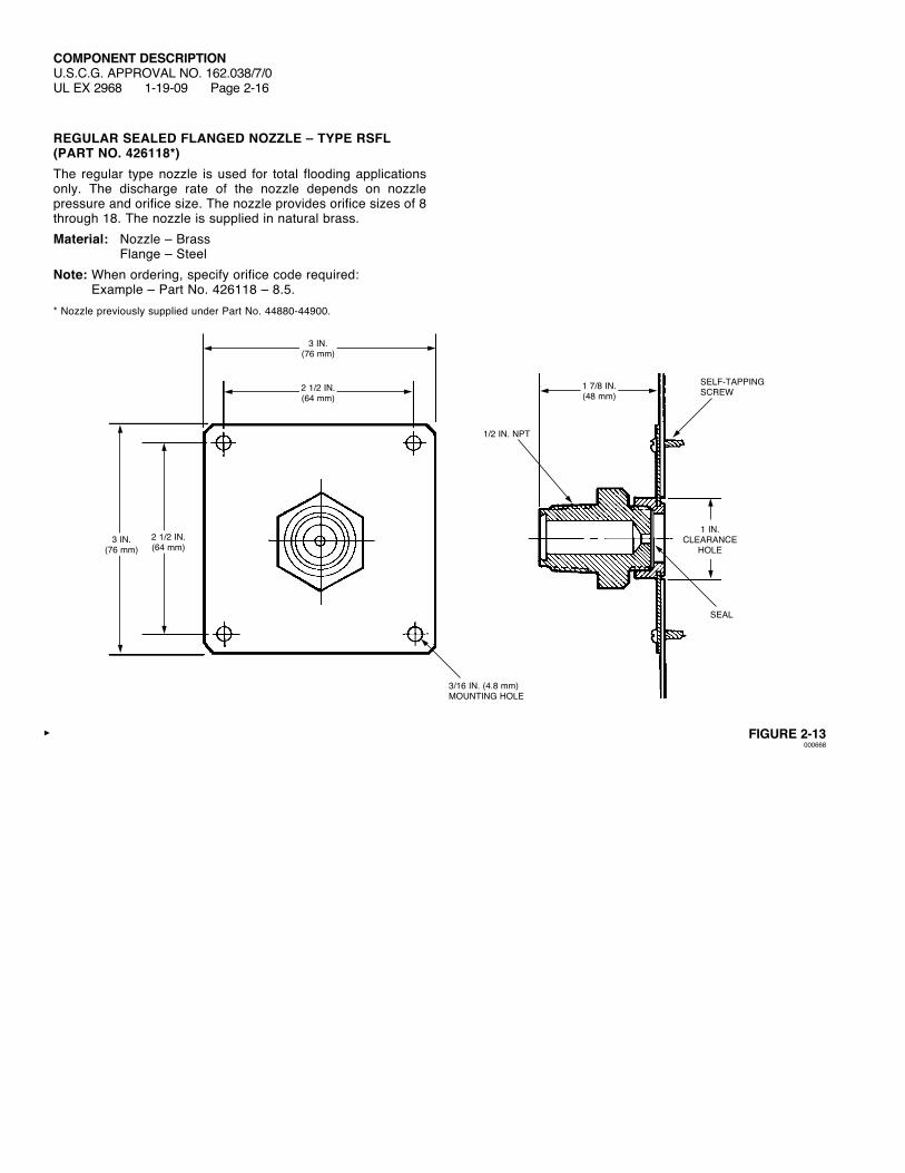
REGULAR SEALED FLANGED NOZZLE – TYPE RSFL (PART NO. 426118*)The regular type nozzle is used for total flooding applications only. The discharge rate of the nozzle depends on nozzle pressure and orifice size. The nozzle provides orifice sizes of 8 through 18. The nozzle is supplied in natural brass.Material: Nozzle – Brass Flange – SteelNote: Whenordering,specifyorificecoderequired:
Example – Part No. 426118 – 8.5.* Nozzle previously supplied under Part No. 44880-44900.
FIGURE 2-13000668
3/16 IN. (4.8 mm) MOUNTING HOLE
SELF-TAPPINGSCREW
SEAL
1/2 IN. NPT
3 IN.(76 mm)
2 1/2 IN.(64 mm)
2 1/2 IN.(64 mm)
3 IN.(76 mm)
1 IN.CLEARANCE
HOLE
1 7/8 IN.(48 mm)
COMPONENT DESCRIPTIONU.S.C.G. APPROVAL NO. 162.038/7/0UL EX 2968 1-19-09 Page 2-17
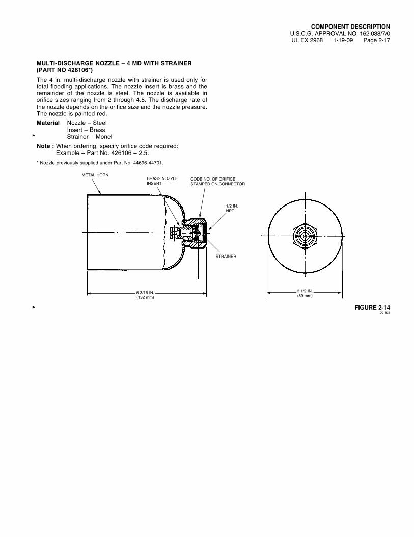
MULTI-DISCHARGE NOZZLE – 4 MD WITH STRAINER (PART NO 426106*)The 4 in. multi-discharge nozzle with strainer is used only for total flooding applications. The nozzle insert is brass and the remainder of the nozzle is steel. The nozzle is available in orifice sizes ranging from 2 through 4.5. The discharge rate of the nozzle depends on the orifice size and the nozzle pressure. The nozzle is painted red.Material Nozzle – Steel Insert – Brass Strainer – MonelNote : Whenordering,specifyorificecoderequired:
Example – Part No. 426106 – 2.5.* Nozzle previously supplied under Part No. 44696-44701.
FIGURE 2-14001831
STRAINER
1/2 IN. NPT
METAL HORNBRASS NOZZLE INSERT
CODE NO. OF ORIFICE STAMPED ON CONNECTOR
3 1/2 IN.(89 mm)
5 3/16 IN.(132 mm)
COMPONENT DESCRIPTIONU.S.C.G. APPROVAL NO. 162.038/7/0UL EX 2968 1-19-09 Page 2-18
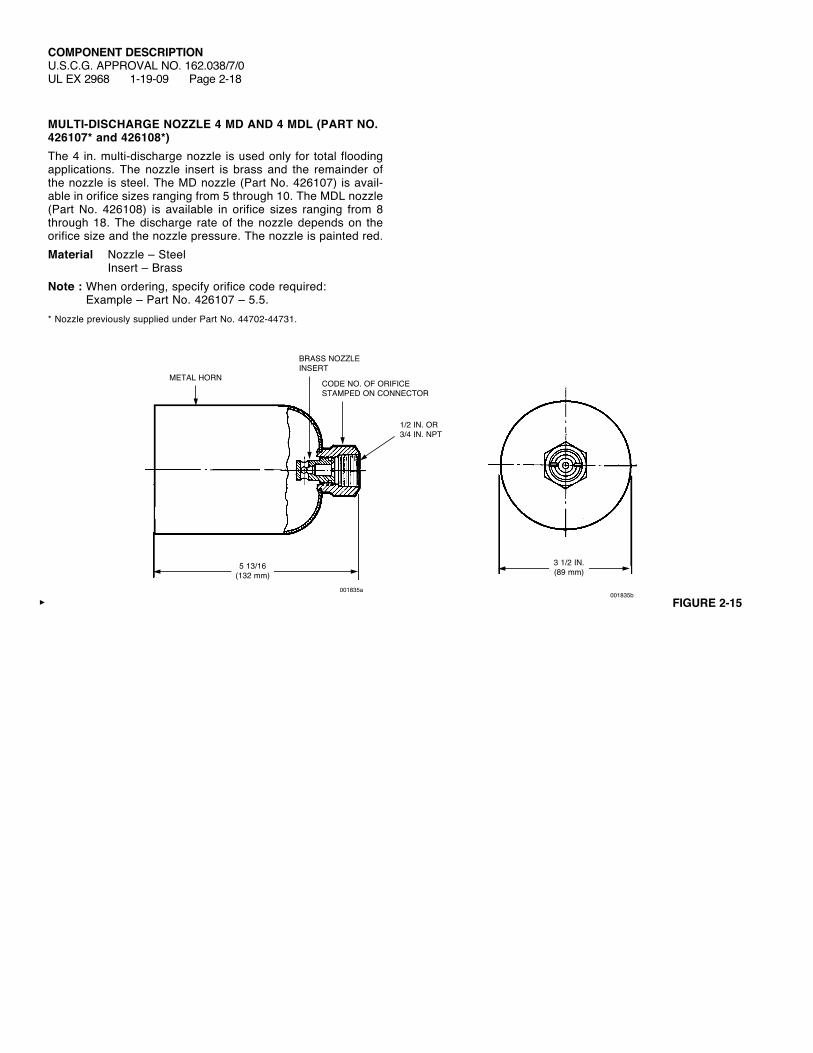
MULTI-DISCHARGE NOZZLE 4 MD AND 4 MDL (PART NO. 426107* and 426108*)The 4 in. multi-discharge nozzle is used only for total flooding applications. The nozzle insert is brass and the remainder of the nozzle is steel. The MD nozzle (Part No. 426107) is avail-able in orifice sizes ranging from 5 through 10. The MDL nozzle (Part No. 426108) is available in orifice sizes ranging from 8 through 18. The discharge rate of the nozzle depends on the orifice size and the nozzle pressure. The nozzle is painted red.Material Nozzle – Steel Insert – BrassNote : Whenordering,specifyorificecoderequired:
Example – Part No. 426107 – 5.5.* Nozzle previously supplied under Part No. 44702-44731.
FIGURE 2-15001835b
METAL HORN
BRASS NOZZLE INSERT
CODE NO. OF ORIFICE STAMPED ON CONNECTOR
1/2 IN. OR 3/4 IN. NPT
5 13/16 (132 mm)
001835a
3 1/2 IN. (89 mm)
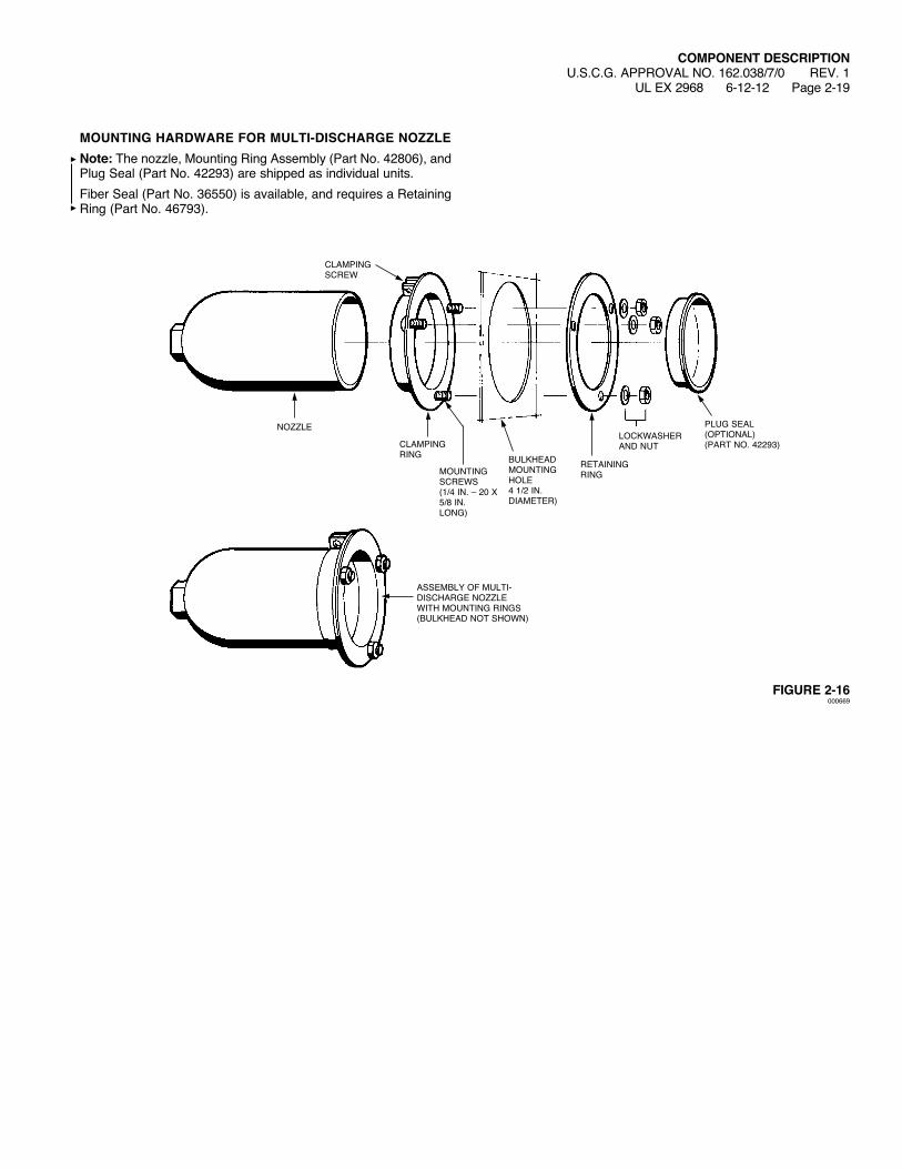
MOUNTING HARDWARE FOR MULTI-DISCHARGE NOZZLENote: The nozzle, Mounting Ring Assembly (Part No. 42806), and Plug Seal (Part No. 42293) are shipped as individual units.Fiber Seal (Part No. 36550) is available, and requires a Retaining Ring (Part No. 46793).
FIGURE 2-16000669
COMPONENT DESCRIPTIONU.S.C.G. APPROVAL NO. 162.038/7/0 REV. 1
UL EX 2968 6-12-12 Page 2-19
ASSEMBLY OF MULTI-DISCHARGE NOZZLEWITHMOUNTINGRINGS(BULKHEADNOTSHOWN)
CLAMPING SCREW
RETAININGRING
LOCKWASHERAND NUT
PLUG SEAL(OPTIONAL)(PART NO. 42293)
MOUNTING SCREWS(1/4 IN. – 20 X 5/8 IN.LONG)
BULKHEADMOUNTINGHOLE4 1/2 IN.DIAMETER)
NOZZLE
CLAMPINGRING

TYPE D DISCHARGE NOZZLE WITH STRAINER (PART NO. 426100*)The type D nozzle with strainer is used primarily for local application and is also listed and approved for use as a total flooding nozzle. The nozzle is painted red with a shell of drawn sheet steel and a brass insert. The type D nozzle with strainer is available in orifice sizes ranging from 1 through 3. The discharge rate of the nozzle depends on the orifice size and nozzle pressure. The area covered in local application is dependent upon the discharge rate and the height of the nozzle above the surface being protected. Height range: 15 to 91 1/2 in. (38 to 232 cm). Discharge rate: 11 to 48.5 lb per minute ( 5 to 22 kg per minute). Material Shell – Steel Insert – Brass Strainer – MonelNote : Whenordering,specifyorificecoderequired:
Example – Part No. 426100 – 2.5.* Nozzle previously supplied under Part No. 44651-44655.
FIGURE 2-17000671
COMPONENT DESCRIPTIONU.S.C.G. APPROVAL NO. 162.038/7/0UL EX 2968 1-19-09 Page 2-20
4 IN.(102 mm)
3 15/32 IN.(88 mm)
DRAWNSTEEL
STRAINER1/2 IN. NPT
ORIFICE
BRASS NOZZLE INSERT
NOZZLE CODE STAMPED HERE
2 IN.(51 mm)
DIAMETER2 1/2 IN.(64 mm)
DIAMETER
COMPONENT DESCRIPTIONU.S.C.G. APPROVAL NO. 162.038/7/0UL EX 2968 1-19-09 Page 2-21
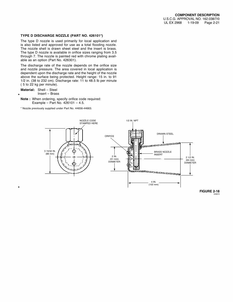
TYPE D DISCHARGE NOZZLE (PART NO. 426101*)The type D nozzle is used primarily for local application and is also listed and approved for use as a total flooding nozzle. The nozzle shell is drawn sheet steel and the insert is brass. The type D nozzle is available in orifice sizes ranging from 3.5 through 7. The nozzle is painted red with chrome plating avail-able as an option (Part No. 426301).The discharge rate of the nozzle depends on the orifice size and nozzle pressure. The area covered in local application is dependent upon the discharge rate and the height of the nozzle above the surface being protected. Height range: 15 in. to 91 1/2 in. (38 to 232 cm). Discharge rate: 11 to 48.5 lb per minute ( 5 to 22 kg per minute). Material: Shell – Steel Insert – BrassNote : Whenordering,specifyorificecoderequired:
Example – Part No. 426101 – 4.5.* Nozzle previously supplied under Part No. 44656-44663.
FIGURE 2-18000672
4 IN.(102 mm)
3 15/32 IN.(88 mm)
DRAWNSTEEL
1/2 IN. NPT
ORIFICE
BRASS NOZZLE INSERT
NOZZLE CODE STAMPED HERE
2 IN.(51 mm)
DIAMETER
2 1/2 IN.(64 mm)
DIAMETER

COMPONENT DESCRIPTIONU.S.C.G. APPROVAL NO. 162.038/7/0UL EX 2968 1-19-09 Page 2-22
SEALED NOZZLE WITH STRAINER (PART NO. 426102*)The sealed nozzle is used primarily in ducts and enclosed machinery spaces. The seal portion of the nozzle is a combi-nation line seal and strainer unit. It is used to prevent dirt or vapors from entering the system piping and also to function as a strainer for the system piping. On operation of the carbon dioxide system, the high pressure of the gas released from the cylinders ruptures the thin sealing disc, allowing an unob-structed flow of gas to the internal discharge nozzle. The sealed nozzle is available in orifice sizes ranging from 2 through 7.The advantage of the sealed nozzle is that it does not require disassembly of the system piping to clean the strainer or replace a ruptured sealing disc. This is accomplished by remov-ing the hex cap on the nozzle.Material: Body – Brass Strainer – MonelNote : Whenordering,specifyorificecoderequired:
Example – Part No. 426102 – 4.5.* Nozzle previously supplied under Part No. 44902-44912.
FIGURE 2-19000673
2 IN.(51 mm)
3 1/4 IN.(83 mm)
1/2 IN. STRAIGHTPIPE THREAD
JAM NUT TO BE USED IF DUCT IS TOO THIN TO BE THREADED
KNURLED RING SEALING DISC RETAINER
MONEL SCREEN – STRAINER
SEALING DISC
CELERONWASHER
NOZZLE
1/2 IN. NPT INLET
BODYSPARE SEALING DISCS
HEX CAP

COMPONENT DESCRIPTIONU.S.C.G. APPROVAL NO. 162.038/7/0UL EX 2968 1-19-09 Page 2-23
GLOBE VALVE WITH MANUALLY OPERATED LEVER Handle Handle Part No. Part No.Valve Valve (Normally (Normally A B C D ESize Part No. Closed) Open) in. (cm) in. (cm) in. (cm) in. (cm) in. (cm)1/2 in. 41451 40238 40248 10 (25.4) 9 3/8 (23.8) 4 3/4 (12.1) 7/8 (2.2) 2 15/16 (7.5)3/4 in. 41102 40239 40267 14 (35.6) 12 3/4 (32.4) 5 5/8 (14.3) 1 1/8 (2.9) 3 5/8 (9.2)1 in. 41354 40239 40267 14 (35.6) 12 3/4 (32.4) 6 3/8 (16.2) 1 7/16 (3.7) 4 1/8 (10.5)1 1/4 in. 41338 40259 46393 17 (43.2) 15 5/8 (39.7) 7 7/8 (20.0) 1 11/16 (4.3) 5 (12.7)1 1/2 in. 41424 40259 46393 17 (43.2) 15 5/8 (39.7) 8 1/4 (21.0) 1 7/8 (4.8) 5 1/2 (14.0)Material: Brass
FIGURE 2-20001427
A
B
*THISDIMENSIONISWITHVALVE IN OPEN POSITION
ALL PIPE THREADS ARE NPT
D
E
C*
PIPE
HANDLE IN OPEN POSITION
HANDLE IN NORMALLY CLOSED POSITION
COMPONENT DESCRIPTIONU.S.C.G. APPROVAL NO. 162.038/7/0UL EX 2968 1-19-09 Page 2-24
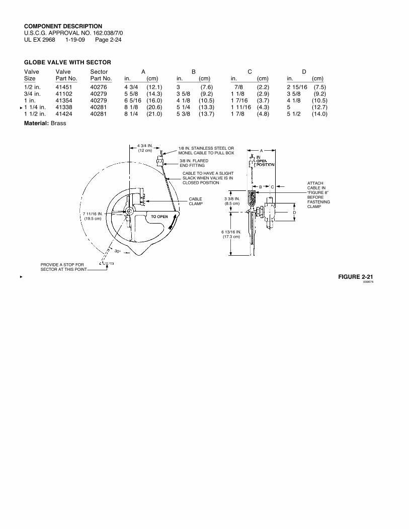
GLOBE VALVE WITH SECTORValve Valve Sector A B C DSize Part No. Part No. in. (cm) in. (cm) in. (cm) in. (cm)1/2 in. 41451 40276 4 3/4 (12.1) 3 (7.6) 7/8 (2.2) 2 15/16 (7.5)3/4 in. 41102 40279 5 5/8 (14.3) 3 5/8 (9.2) 1 1/8 (2.9) 3 5/8 (9.2)1 in. 41354 40279 6 5/16 (16.0) 4 1/8 (10.5) 1 7/16 (3.7) 4 1/8 (10.5)1 1/4 in. 41338 40281 8 1/8 (20.6) 5 1/4 (13.3) 1 11/16 (4.3) 5 (12.7)1 1/2 in. 41424 40281 8 1/4 (21.0) 5 3/8 (13.7) 1 7/8 (4.8) 5 1/2 (14.0)Material: Brass
FIGURE 2-21000674
CABLE CLAMP
1/8 IN. STAINLESS STEEL OR MONEL CABLE TO PULL BOX
3/8 IN. FLAREDEND FITTING
CABLE TO HAVE A SLIGHT SLACKWHENVALVEISINCLOSED POSITION
PROVIDE A STOP FOR SECTOR AT THIS POINT
30°
4 3/4 IN.(12 cm)
7 11/16 IN.(19.5 cm)
D
3 3/8 IN.(8.5 cm)
6 13/16 IN.(17.3 cm)
A
B CATTACH CABLE IN “FIGURE 8” BEFOREFASTENING CLAMP

COMPONENT DESCRIPTIONU.S.C.G. APPROVAL NO. 162.038/7/0
UL EX 2968 3-20-12 Page 2-24.1
1 IN. – 4 IN. LOCKOUT VALVESThe lockout valve is a manually-operated ball valve installed in various locations in the piping system. The valve is used to inhibit the discharge of carbon dioxide into an entire system or a specific area of a system when maintenance of the system or entry into the protected space is required. The valve is equipped with a locking device to padlock the valve in the open or closed position.
Valve Material:1 in. and 2 in. Valves – Stainless Steel Body
316 SS Ball, Stem, and Hardware Reinforced Teflon Seats
3 in. and 4 in. Valves – Corrosion-Resistant Painted Steel Body 316 SS Ball, Stem, and Hardware Reinforced Teflon Seats
Port:1 in. and 2 in. Valves – Standard3 in. and 4 in. Valves – Full
1 in. and 2 in. Lockout Valves
Dimension Dimension Dimension A B C Depth WeightPart No. Valve Size in. (mm) in. (mm) in. (mm) in. (mm) lb (kg)435935 1 in. 3.25 (83) 2.24 (57) 5.75 (146) 1.62 (41) 2.5 (1.1)435936 2 in. 4.65 (118) 2.91 (74) 7.63 (194) 2.75 (70) 6.5 (2.9)
FIGURE 2-21.1008998
A
C
B
COMPONENT DESCRIPTIONU.S.C.G. APPROVAL NO. 162.038/7/0UL EX 2968 3-20-12 Page 2-24.2
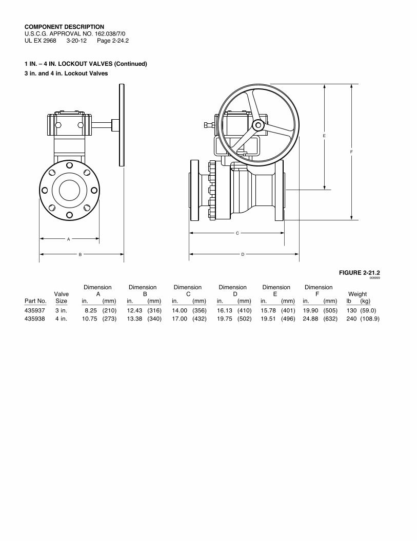
1 IN. – 4 IN. LOCKOUT VALVES (Continued)3 in. and 4 in. Lockout Valves
Dimension Dimension Dimension Dimension Dimension Dimension Valve A B C D E F WeightPart No. Size in. (mm) in. (mm) in. (mm) in. (mm) in. (mm) in. (mm) lb (kg)435937 3 in. 8.25 (210) 12.43 (316) 14.00 (356) 16.13 (410) 15.78 (401) 19.90 (505) 130 (59.0)435938 4 in. 10.75 (273) 13.38 (340) 17.00 (432) 19.75 (502) 19.51 (496) 24.88 (632) 240 (108.9)
FIGURE 2-21.2008999
A
D
C
E
F
B
COMPONENT DESCRIPTIONU.S.C.G. APPROVAL NO. 162.038/7/0UL EX 2968 1-19-09 Page 2-25
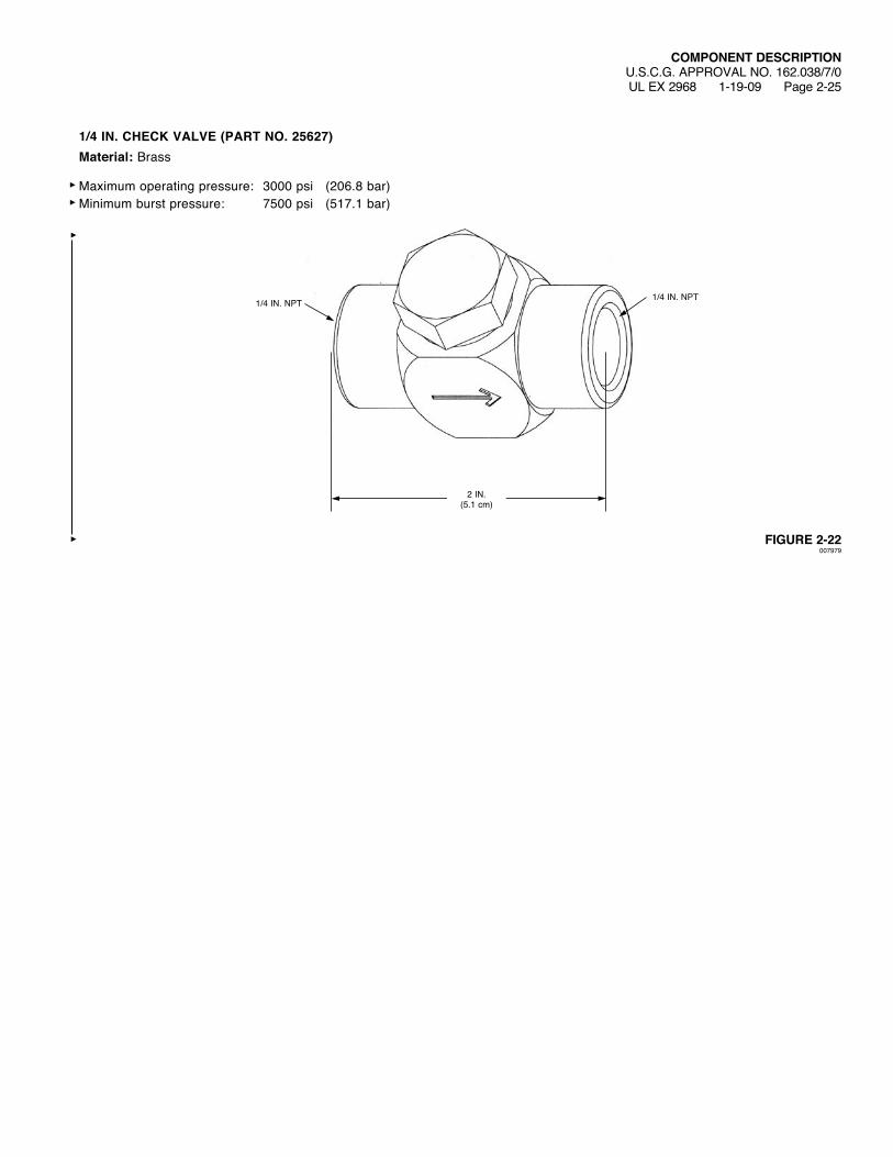
1/4 IN. CHECK VALVE (PART NO. 25627)Material: Brass
Maximum operating pressure: 3000 psi (206.8 bar)Minimum burst pressure: 7500 psi (517.1 bar)
FIGURE 2-22007979
1/4 IN. NPT1/4 IN. NPT
2 IN.(5.1 cm)

COMPONENT DESCRIPTIONU.S.C.G. APPROVAL NO. 162.038/7/0UL EX 2968 1-19-09 Page 2-26
1/2 IN. CHECK VALVE (PART NO. 40860)Material: BronzeThreads: 1/2 in. – 14 FNPT (both ends)Approximate Weight: 2 lb (0.9 kg)
FIGURE 2-23000679
FLOW
3 IN.(7.6 cm)
2 5/8 IN.(6.7 cm)
1 3/4 IN.(4.4 cm)
BONNET
SPRING
CHECK
BODY

COMPONENT DESCRIPTIONU.S.C.G. APPROVAL NO. 162.038/7/0UL EX 2968 1-19-09 Page 2-27
3/4 IN. CHECK VALVE (PART NO. 40852)Material: BronzeThreads: 3/4 in. – 14 FNPT (both ends)Approximate Weight: 4 lb (1.8 kg)
FIGURE 2-24000679
FLOW
3 5/8 IN.(9.2 cm)
3 1/8 IN.(7.9 cm)
2 1/16 IN.(5.2 cm)
BONNET
SPRING
CHECK
BODY
COMPONENT DESCRIPTIONU.S.C.G. APPROVAL NO. 162.038/7/0UL EX 2968 1-19-09 Page 2-28
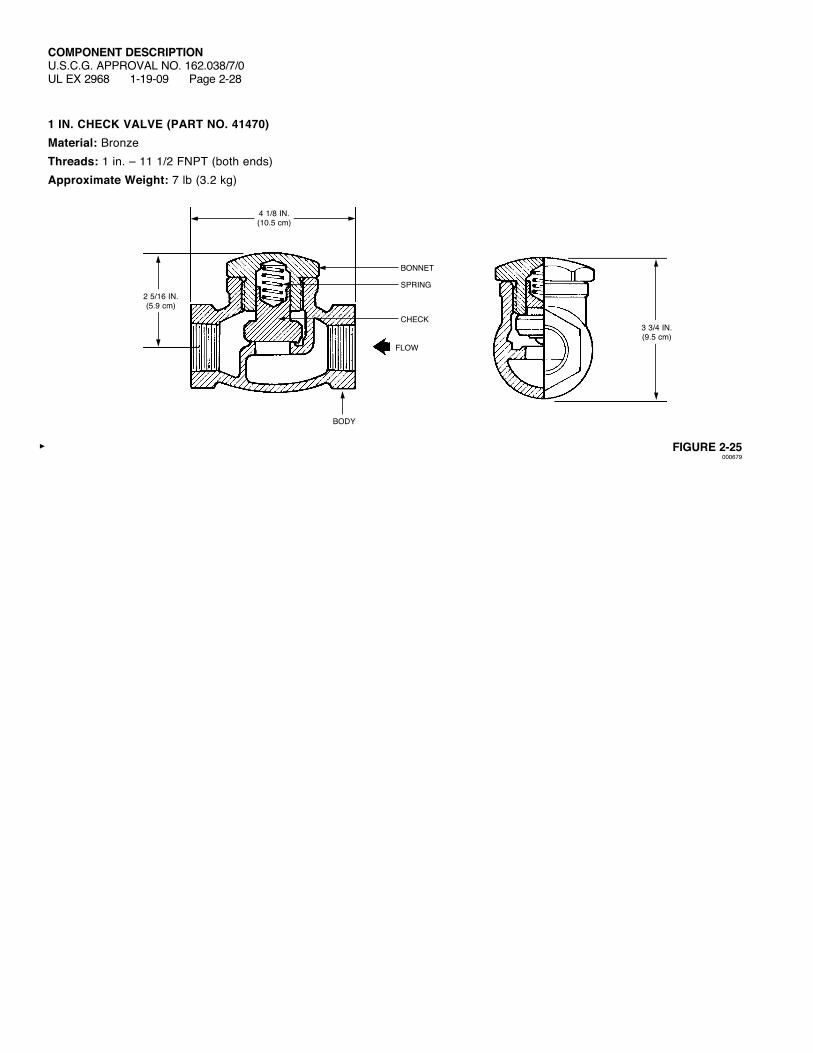
1 IN. CHECK VALVE (PART NO. 41470)Material: BronzeThreads: 1 in. – 11 1/2 FNPT (both ends)Approximate Weight: 7 lb (3.2 kg)
FIGURE 2-25000679
FLOW
4 1/8 IN.(10.5 cm)
3 3/4 IN.(9.5 cm)
2 5/16 IN.(5.9 cm)
BONNET
SPRING
CHECK
BODY

COMPONENT DESCRIPTIONU.S.C.G. APPROVAL NO. 162.038/7/0UL EX 2968 1-19-09 Page 2-29
1 1/4 IN. CHECK VALVE (PART NO. 41549)Material: BronzeThreads: 1 1/4 in. – 11 1/2 FNPT (both ends)Approximate Weight: 10 lb (8.7 kg)
FIGURE 2-26000679
FLOW
5 IN.(12.7 cm)
4 1/2 IN.(11.4 cm)
2 3/16 IN.(7.1 cm)
BONNET
SPRING
CHECK
BODY

COMPONENT DESCRIPTIONU.S.C.G. APPROVAL NO. 162.038/7/0UL EX 2968 1-19-09 Page 2-30
1 1/2 IN. CHECK VALVE (PART NO. 41463)Material: BronzeThreads: 1 1/2 in. – 11 1/2 FNPT (both ends)Approximate Weight: 13 lb (5.9 kg)
FIGURE 2-27000679
FLOW
5 1/2 IN.(14 cm)
5 1/8 IN.(13 cm)
3 1/4 IN.(8.3 cm)
BONNET
SPRING
CHECK
BODY

COMPONENT DESCRIPTIONU.S.C.G. APPROVAL NO. 162.038/7/0UL EX 2968 1-19-09 Page 2-31
2 IN. CHECK VALVE (PART NO. 40649)Material: BronzeThreads: 2 in. – 11 1/2 FNPT (both ends)Approximate Weight: 15 lb (6.8 kg)
FIGURE 2-28
6 1/2 IN.(16.5 cm)
002739
DIRECTIONOFFLOW
CHECK
BODY
BONNET
SPRING
6 7/16 IN.(16.4 cm)
3 1/2 IN.(8.9 cm)
COMPONENT DESCRIPTIONU.S.C.G. APPROVAL NO. 162.038/7/0 REV. 1UL EX 2968 6-12-12 Page 2-32
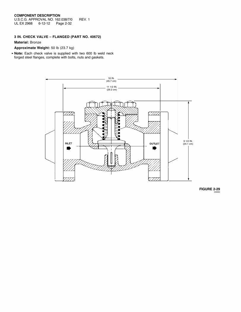
3 IN. CHECK VALVE – FLANGED (PART NO. 40672)Material: BronzeApproximate Weight: 50 lb (23.7 kg)Note: Each check valve is supplied with two 600 lb weld neck forged steel flanges, complete with bolts, nuts and gaskets.
FIGURE 2-29000683
11 1/2 IN.(29.2 cm)
18 IN.(45.7 cm)
9 1/2 IN.(24.1 cm)

COMPONENT DESCRIPTIONU.S.C.G. APPROVAL NO. 162.038/7/0UL EX 2968 1-19-09 Page 2-33
MANUAL PULL BOX – TYPE ‘‘A’’ (PART NO. 41527)Material: Brass
FIGURE 2-30000676
2 3/16 IN.(5.6 cm)
MOISTUREPROOF JOINT
PULLHANDLE
GLASS FRONT
CAST BRASS HINGED COVER (PAINTED RED)
CAST BRASS BODY (PAINTED RED)
1/8 IN. STAINLESS STEEL PULL CABLE
STOWAGESPACEFOR SPARE BREAK GLASS
SPRING FORCES HANDLE OUT INTO OPERATING POSITIONWHENGLASS IS BROKEN
3/8 IN. PIPE TO ENCLOSE PULL CABLE
4 7/16 IN.(11.3 cm)
3 1/4 IN.(8.3 cm)
4 – 3/32 IN. (2.4 mm) DIAMETERMOUNTING HOLES
PROTECTED HAZARD ENGRAVED INNAMEPLATE (SPECIFY)
4 7/8 IN.(12.4 cm)
3 IN.(7.6 cm)
BRASS HAM-MER AND CHAIN SECURED TO BOX
IN CASE OF FIREBREAK GLASS ANDPULL HANDLE HARD
UNTIL RED PAINTMARK ON CABLE
SHOWS

COMPONENT DESCRIPTIONU.S.C.G. APPROVAL NO. 162.038/7/0UL EX 2968 1-19-09 Page 2-34
MANUAL PULL BOX – TYPE ‘‘B’’ (PART NO. 43827)Material: Brass
FIGURE 2-31000684
3 1/8 IN.(7.9 cm)
MOISTUREPROOF JOINT
PULLHANDLE
GLASS
DRAIN HOLE
CAST BRASS HINGED COVER
“O” RINGGASKET
CAST BRASS HINGED FRONTWITHGLASS
LEVER TYPE LATCH
BRASS HAMMER AND CHAIN SECURED TO BOX
4 – 9/32 IN. (7.1 mm) DIAMETERMOUNTING HOLES
PROTECTED HAZARD ENGRAVED INNAMEPLATE (SPECIFY)
IN CASE OF FIRERELEASE LATCHES,OPEN DOOR, BREAK
GLASS AND PULLHANDLE HARD UNTILRED PAINT MARK ON
CABLESHOWS
CAST BRASS BODY (PAINTED RED)
1/8 IN. STAINLESS STEEL PULL CABLE
STOWAGESPACEFOR SPARE DISCS ANDWASHERS
SPRING FORCES HANDLE OUT INTO OPERATING POSITIONWHENGLASS IS BROKEN
3/8 IN. CONDUIT TO ENCLOSE PULL CABLE
3 1/4 IN.(8.3 cm)
6 3/4 IN.(17.1 cm)
4 7/8 IN.(12.4 cm)
3 IN.(7.6 cm)
COMPONENT DESCRIPTIONU.S.C.G. APPROVAL NO. 162.038/7/0UL EX 2968 1-19-09 Page 2-35
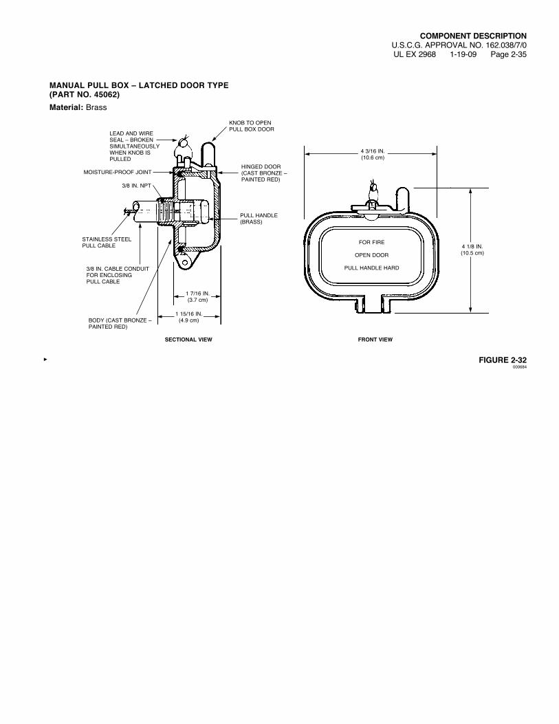
MANUAL PULL BOX – LATCHED DOOR TYPE (PART NO. 45062)Material: Brass
FIGURE 2-32000684
PULL HANDLE (BRASS)
MOISTURE-PROOF JOINT
3/8 IN. CABLE CONDUIT FOR ENCLOSINGPULL CABLE
BODY (CAST BRONZE – PAINTED RED)
3/8 IN. NPT
STAINLESS STEEL PULL CABLE
KNOB TO OPEN PULL BOX DOOR
LEADANDWIRESEAL – BROKEN SIMULTANEOUSLY WHENKNOBISPULLED
HINGED DOOR (CAST BRONZE – PAINTED RED)
FRONT VIEWSECTIONAL VIEW
FOR FIRE
OPEN DOOR
PULL HANDLE HARD
1 7/16 IN.(3.7 cm)
1 15/16 IN.(4.9 cm)
4 1/8 IN.(10.5 cm)
4 3/16 IN.(10.6 cm)
COMPONENT DESCRIPTIONU.S.C.G. APPROVAL NO. 162.038/7/0 REV. 1UL EX 2968 3-20-12 Page 2-36
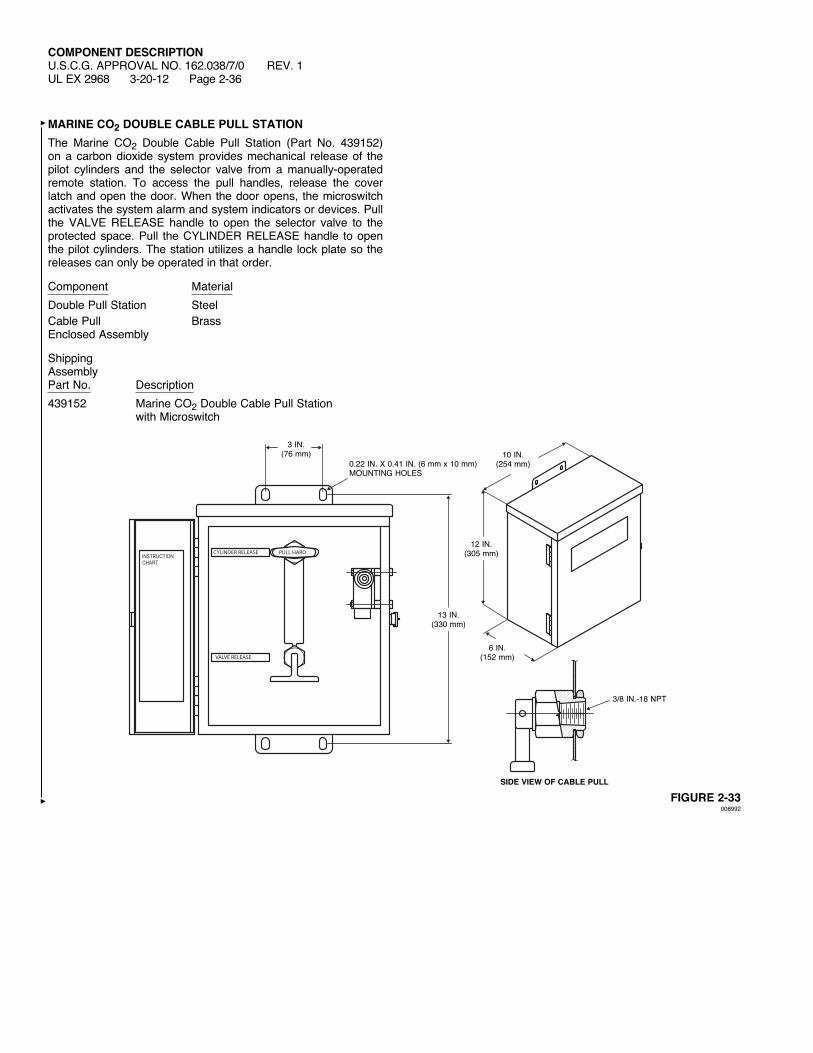
MARINE CO2 DOUBLE CABLE PULL STATIONThe Marine CO2 Double Cable Pull Station (Part No. 439152) on a carbon dioxide system provides mechanical release of the pilot cylinders and the selector valve from a manually-operated remote station. To access the pull handles, release the cover latchandopenthedoor.Whenthedooropens, themicroswitchactivates the system alarm and system indicators or devices. Pull the VALVE RELEASE handle to open the selector valve to the protected space. Pull the CYLINDER RELEASE handle to open the pilot cylinders. The station utilizes a handle lock plate so the releases can only be operated in that order.
Component MaterialDouble Pull Station SteelCable Pull Brass Enclosed Assembly
ShippingAssemblyPart No. Description439152 Marine CO2 Double Cable Pull Station with Microswitch
PULL HARD
VALVE RELEASE
CYLINDER RELEASEINSTRUCTION CHART
FIGURE 2-33008992
10 IN.(254 mm)
12 IN.(305 mm)
6 IN.(152 mm)
13 IN.(330 mm)
3/8 IN.-18 NPT
0.22 IN. X 0.41 IN. (6 mm x 10 mm) MOUNTING HOLES
SIDE VIEW OF CABLE PULL
3 IN.(76 mm)

COMPONENT DESCRIPTIONU.S.C.G. APPROVAL NO. 162.038/7/0UL EX 2968 1-19-09 Page 2-37
DUAL/TRIPLE CONTROL BOX – SHORT (PART NO. 42784)
FIGURE 2-34000685
13 3/4 IN.(34.9 cm)
12 1/4 IN.(31.1 cm)
DIRECTION OF PULLCABLE CLAMP
CABLE PULL FROM PULL-BOXES
CABLE-PULL TO CYLINDER RELEASE
3/8 IN. PIPE OR 1/2 IN. E.M.T.
FLEXIBLE TRANSPARENT PROTECTION RING
4 – 9/32 IN. (7.1 mm) DIAMETERMOUNTING HOLES
JUNCTION BOX (SHOWN WITHOUT COVER)
REMOVABLE COVER
NOTE: THE SHORT BOX IS USED FOR LEVER RELEASES ONLY.
3 1/4 IN. (8.3 cm)
2 3/4 IN.(7.0 cm)
1 IN. (2.5 cm)
1/2 IN. (1.3 cm)
5/8 IN. (1.6 cm)
11/16 IN. (1.7 cm)
1 7/8 IN.(4.8 cm)
END VIEW

COMPONENT DESCRIPTIONU.S.C.G. APPROVAL NO. 162.038/7/0UL EX 2968 1-19-09 Page 2-38
DUAL/TRIPLE CONTROL BOX – LONG (PART NO. 43166)
FIGURE 2-35000685
REMOVABLE COVER
3 1/4 IN. (8.3 cm)
2 3/4 IN.(7.0 cm)
1 IN. (2.5 cm)
1/2 IN. (1.3 cm)
5/8 IN. (1.6 cm)
11/16 IN. (1.7 cm)
1 7/8 IN.(4.8 cm)
END VIEW
20 3/4 IN.(52.7 cm)
19 1/4 IN.(48.9 cm)
DIRECTION OF PULLCABLE CLAMP
CABLE PULL FROM PULL-BOXES
CABLE-PULL TO CYLINDER RELEASE
3/8 IN. CONDUIT
FLEXIBLE TRANSPARENT PROTECTION RING4 – 9/32 IN. (7.1 mm)
DIAMETERMOUNTING HOLES
JUNCTION BOX (SHOWN WITHOUT COVER)
“A”“B”“C”
NOTE: THE LONG BOX IS USED FOR GLOBE VALVES AND SECTORS ONLY.

COMPONENT DESCRIPTIONU.S.C.G. APPROVAL NO. 162.038/7/0UL EX 2968 1-19-09 Page 2-39
REMOTE CABLE PULL EQUALIZER – SHORT (PART NO. 42791)
FIGURE 2-36000688
NOTE: THE SHORT BOX IS USED FOR LEVER RELEASES ONLY.
13 3/4 IN.(34.9 cm)
12 1/4 IN.(31.1 cm)
1 7/8 IN.(4.8 cm)
DIRECTION OF PULL
CABLE CLAMP
CABLE TO PULL BOX
REMOVABLE COVER
1 IN. (2.5 cm)
11/16 IN. (1.7 cm)
CABLE FROM CYLINDER AND VALVE RELEASES
FLEXIBLE TRANSPARENT PROTECTION RING
4 – 9/32 IN. (7.1 mm) DIAMETERMOUNTING HOLES
EQUALIZER BOX (SHOWN WITHOUT COVER)
END VIEW
3/8 IN. PIPE
2 3/4 IN.(7.0 cm)
3 1/4 IN. (8.3 cm)
COMPONENT DESCRIPTIONU.S.C.G. APPROVAL NO. 162.038/7/0UL EX 2968 1-19-09 Page 2-40
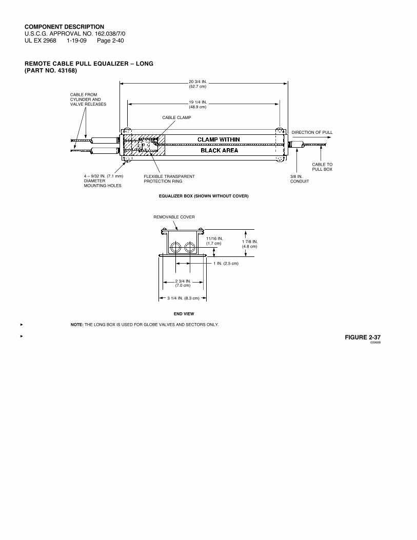
REMOTE CABLE PULL EQUALIZER – LONG (PART NO. 43168)
FIGURE 2-37000688
20 3/4 IN.(52.7 cm)
19 1/4 IN.(48.9 cm)
1 7/8 IN.(4.8 cm)
DIRECTION OF PULL
CABLE CLAMP
CABLE TO PULL BOX
REMOVABLE COVER
1 IN. (2.5 cm)
11/16 IN. (1.7 cm)
CABLE FROM CYLINDER AND VALVE RELEASES
FLEXIBLE TRANSPARENT PROTECTION RING
4 – 9/32 IN. (7.1 mm) DIAMETERMOUNTING HOLES
EQUALIZER BOX (SHOWN WITHOUT COVER)
END VIEW
3/8 IN. CONDUIT
2 3/4 IN.(7.0 cm)
3 1/4 IN. (8.3 cm)
NOTE: THE LONG BOX IS USED FOR GLOBE VALVES AND SECTORS ONLY.

COMPONENT DESCRIPTIONU.S.C.G. APPROVAL NO. 162.038/7/0 REV. 1
UL EX 2968 6-12-12 Page 2-41
1/16 IN. PULL CABLE WITH END FITTINGCable Length Cableft (m) Part No. 50 (15.2) 42104100 (30.5) 42109150 (45.7) 42113200 (61.0) 42128
NOTICEThe strength of the end fitting exceeds the breaking point of the cable.
FIGURE 2-38000689
SLOT IN COUPLING FOR INSTALLATION OF CABLE END FITTING
HANDLE
CABLE END (BRASS)
COUPLING
STAINLESSSTEELCABLEWITHSWAGEDCABLE END FOR PULL BOX, CABLE END HAVING RED PAINT MARK

COMPONENT DESCRIPTIONU.S.C.G. APPROVAL NO. 162.038/7/0UL EX 2968 1-19-09 Page 2-42
CORNER PULLEY – NYLON SHEAVE (PART NO. 42678)Material: BrasswithNylonSheave(Watertight)
FIGURE 2-39000690
3/8 IN. PIPE
3/8 IN. NPT
REMOVABLE FACE FOR RUNNING CABLE
1 5/32 IN.(2.8 cm)
2 11/16 IN.(6.8 cm)
4 3/16 IN.(10.6 cm)
RIGHT AND LEFT HAND ADAPTOR SUPPLIEDWHENREQUIRED, PART NO. 40696
LEAD-CLADCOPPER GASKET

COMPONENT DESCRIPTIONU.S.C.G. APPROVAL NO. 162.038/7/0UL EX 2968 1-19-09 Page 2-43
CORNER PULLEY – BRASS SHEAVE (PART NO. 45515)Material: Brass
FIGURE 2-40000690
3/8 IN. PIPE
3/8 IN. NPT
REMOVABLE FACE FOR RUNNING CABLE
1 5/32 IN.(2.8 cm)
2 11/16 IN.(6.8 cm)
4 3/16 IN.(10.6 cm)
RIGHT AND LEFT HAND ADAPTOR SUPPLIEDWHENREQUIRED, PART NO. 40696
1/16 1/8
COMPONENT DESCRIPTIONU.S.C.G. APPROVAL NO. 162.038/7/0UL EX 2968 1-19-09 Page 2-44
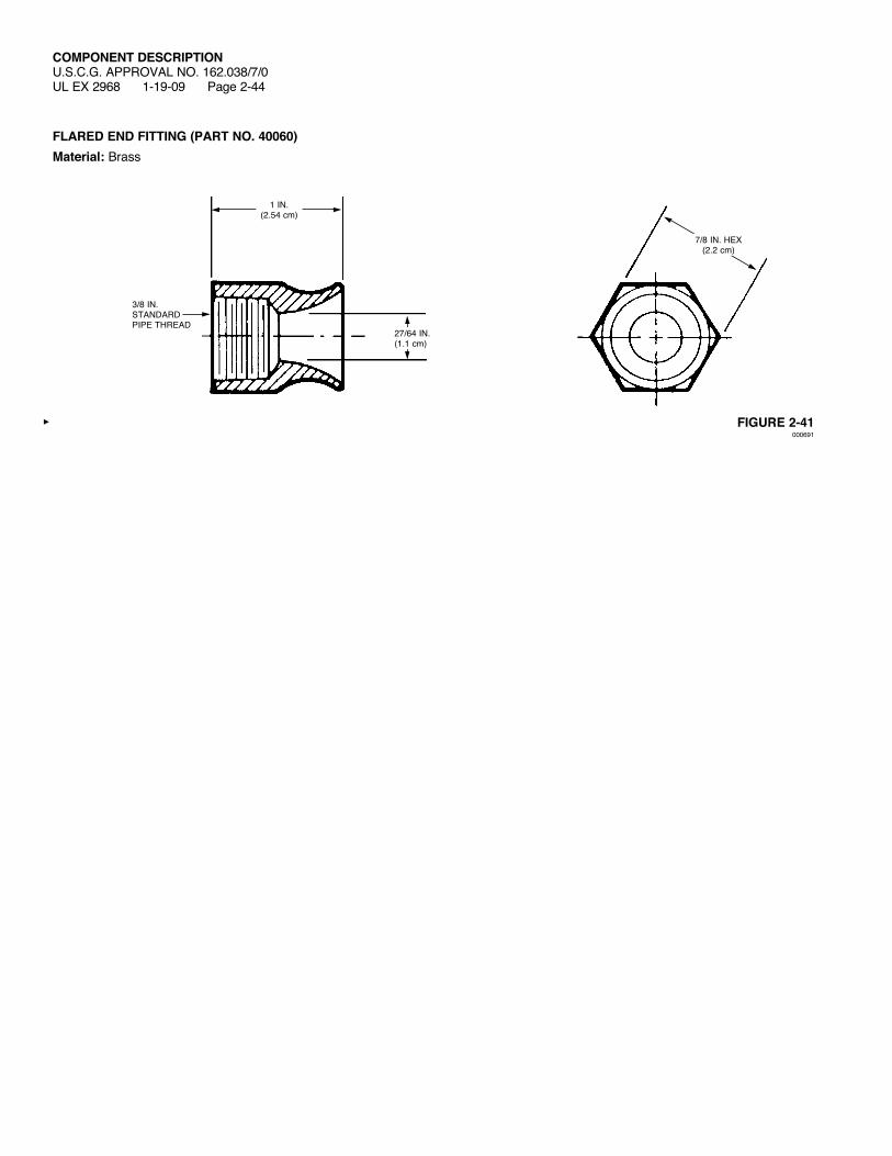
FLARED END FITTING (PART NO. 40060)Material: Brass
FIGURE 2-41000691
3/8 IN.STANDARD PIPE THREAD
1 IN.(2.54 cm)
7/8 IN. HEX(2.2 cm)
27/64 IN.(1.1 cm)
COMPONENT DESCRIPTIONU.S.C.G. APPROVAL NO. 162.038/7/0UL EX 2968 1-19-09 Page 2-45
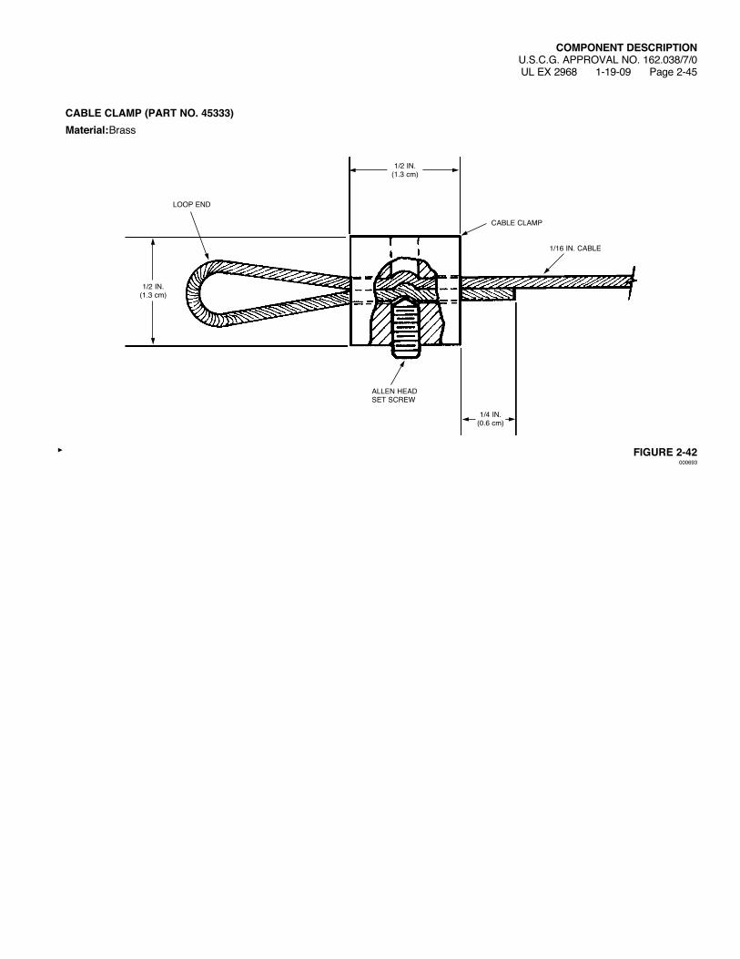
CABLE CLAMP (PART NO. 45333)Material: Brass
FIGURE 2-42000693
ALLEN HEADSETSCREW
1/16 IN. CABLE
CABLE CLAMP
1/2 IN.(1.3 cm)
1/2 IN.(1.3 cm)
1/4 IN.(0.6 cm)
LOOP END
COMPONENT DESCRIPTIONU.S.C.G. APPROVAL NO. 162.038/7/0 REV. 2UL EX 2968 6-12-12 Page 2-46
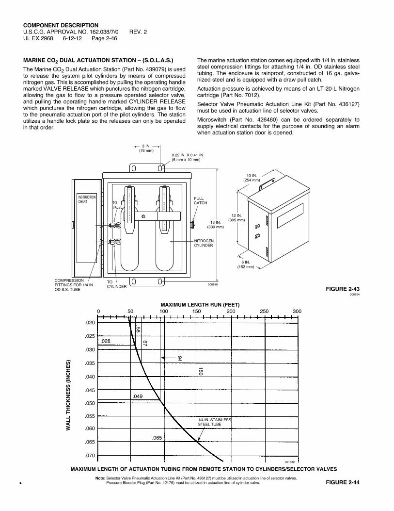
MARINE CO2 DUAL ACTUATION STATION – (S.O.L.A.S.)The Marine CO2 Dual Actuation Station (Part No. 439079) is used to release the system pilot cylinders by means of compressed nitrogen gas. This is accomplished by pulling the operating handle marked VALVE RELEASE which punctures the nitrogen cartridge, allowing the gas to flow to a pressure operated selector valve, and pulling the operating handle marked CYLINDER RELEASE which punctures the nitrogen cartridge, allowing the gas to flow to the pneumatic actuation port of the pilot cylinders. The station utilizes a handle lock plate so the releases can only be operated in that order.
The marine actuation station comes equipped with 1/4 in. stainless steel compression fittings for attaching 1/4 in. OD stainless steel tubing. The enclosure is rainproof, constructed of 16 ga. galva-nized steel and is equipped with a draw pull catch.Actuation pressure is achieved by means of an LT-20-L Nitrogen cartridge (Part No. 7012).Selector Valve Pneumatic Actuation Line Kit (Part No. 436127) must be used in actuation line of selector valves.Microswitch (Part No. 426460) can be ordered separately to supply electrical contacts for the purpose of sounding an alarm when actuation station door is opened.
FIGURE 2-44
001382
MAXIMUM LENGTH RUN (FEET) 0 50 100 150 200 250 300
WA
LL T
HIC
KN
ESS
(INC
HES
)
1/4 IN. STAINLESS STEEL TUBE
.028
.049
.065
5867
94
150
.020
.025
.030
.035
.040
.045
.050
.055
.060
.065
.070
MAXIMUM LENGTH OF ACTUATION TUBING FROM REMOTE STATION TO CYLINDERS/SELECTOR VALVESNote: Selector Valve Pneumatic Actuation Line Kit (Part No. 436127) must be utilized in actuation line of selector valves.
Pressure Bleeder Plug (Part No. 42175) must be utilized in actuation line of cylinder valve.
FIGURE 2-43000694
1
VALVE
RELEASE
2
CYLI
NDER
EASE
008990
10 IN.(254 mm)
6 IN.(152 mm)
12 IN.(305 mm)13 IN.
(330 mm)
3 IN.(76 mm)
INSTRUCTIONCHART
TOCYLINDER
COMPRESSION FITTINGS FOR 1/4 IN. OD S.S. TUBE
TO VALVE
PULLCATCH
0.22 IN. X 0.41 IN.(6 mm x 10 mm)
NITROGENCYLINDER
COMPONENT DESCRIPTIONU.S.C.G. APPROVAL NO. 162.038/7/0 REV. 1
UL EX 2968 3-20-12 Page 2-47
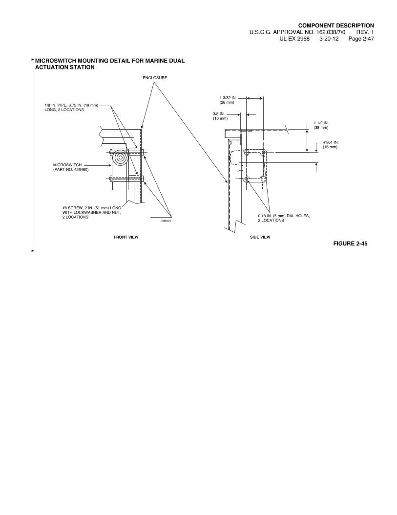
MICROSWITCH MOUNTING DETAIL FOR MARINE DUAL ACTUATION STATION
008991
FIGURE 2-45
0.18 IN. (5 mm) DIA. HOLES,2 LOCATIONS
SIDE VIEWFRONT VIEW
ENCLOSURE
MICROSWITCH(PART NO. 426460)
1/8 IN. PIPE, 0.75 IN. (19 mm) LONG, 2 LOCATIONS
#8SCREW,2IN.(51 mm) LONG WITHLOCKWASHERANDNUT,2 LOCATIONS
3/8 IN.(10 mm)
1 3/32 IN.(28 mm)
1 1/2 IN.(38 mm)
41/64 IN.(16 mm)
COMPONENT DESCRIPTIONU.S.C.G. APPROVAL NO. 162.038/7/0 REV. 2UL EX 2968 6-12-12 Page 2-48
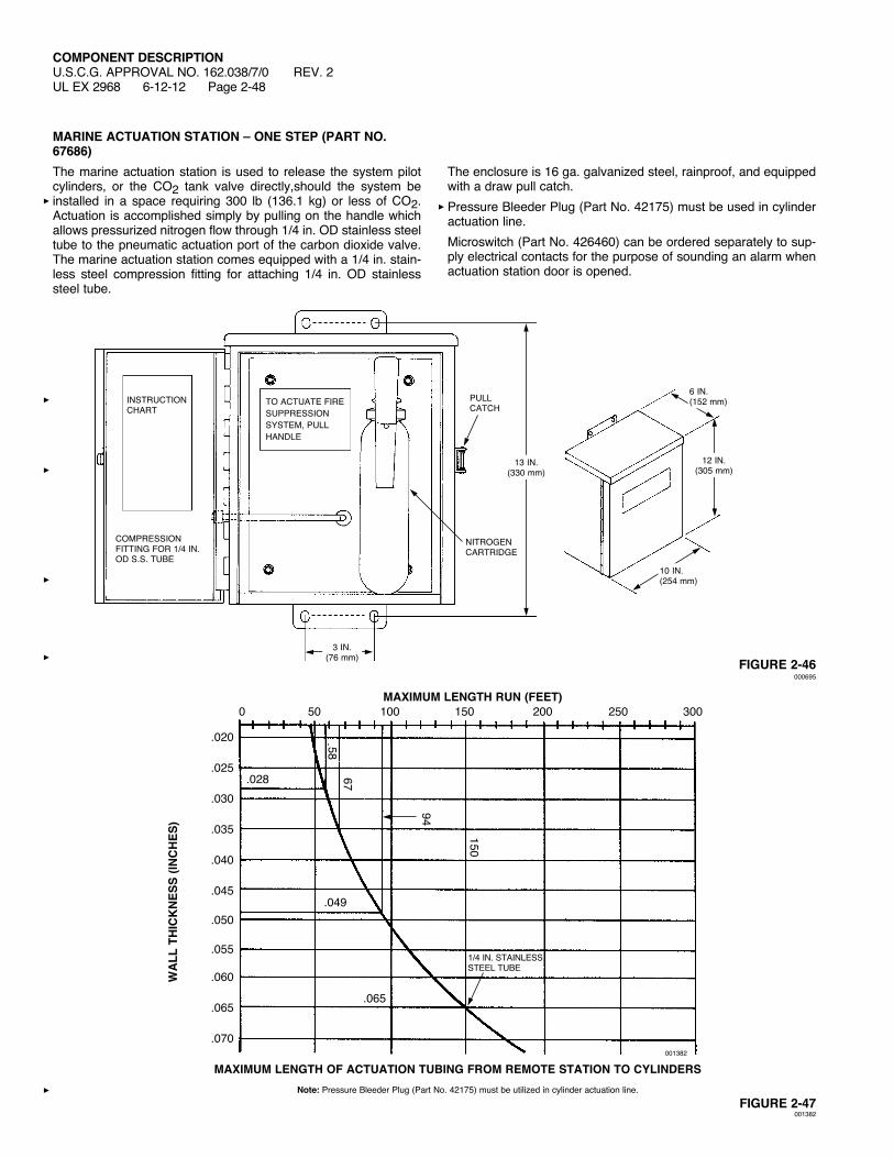
MARINE ACTUATION STATION – ONE STEP (PART NO. 67686)The marine actuation station is used to release the system pilot cylinders, or the CO2 tank valve directly,should the system be installed in a space requiring 300 lb (136.1 kg) or less of CO2. Actuation is accomplished simply by pulling on the handle which allows pressurized nitrogen flow through 1/4 in. OD stainless steel tube to the pneumatic actuation port of the carbon dioxide valve. The marine actuation station comes equipped with a 1/4 in. stain-less steel compression fitting for attaching 1/4 in. OD stainless steel tube.
The enclosure is 16 ga. galvanized steel, rainproof, and equipped with a draw pull catch.Pressure Bleeder Plug (Part No. 42175) must be used in cylinder actuation line.Microswitch (Part No. 426460) can be ordered separately to sup-ply electrical contacts for the purpose of sounding an alarm when actuation station door is opened.
FIGURE 2-46000695
FIGURE 2-47001382
001382
MAXIMUM LENGTH RUN (FEET) 0 50 100 150 200 250 300
WA
LL T
HIC
KN
ESS
(INC
HES
)
1/4 IN. STAINLESS STEEL TUBE
.028
.049
.065
5867
94
150
.020
.025
.030
.035
.040
.045
.050
.055
.060
.065
.070
MAXIMUM LENGTH OF ACTUATION TUBING FROM REMOTE STATION TO CYLINDERSNote: Pressure Bleeder Plug (Part No. 42175) must be utilized in cylinder actuation line.
NITROGENCARTRIDGE
COMPRESSION FITTING FOR 1/4 IN. OD S.S. TUBE
PULL CATCH
INSTRUCTIONCHART
TO ACTUATE FIRE SUPPRESSION SYSTEM, PULLHANDLE
6 IN.(152 mm)
12 IN.(305 mm)
13 IN.(330 mm)
3 IN.(76 mm)
10 IN.(254 mm)
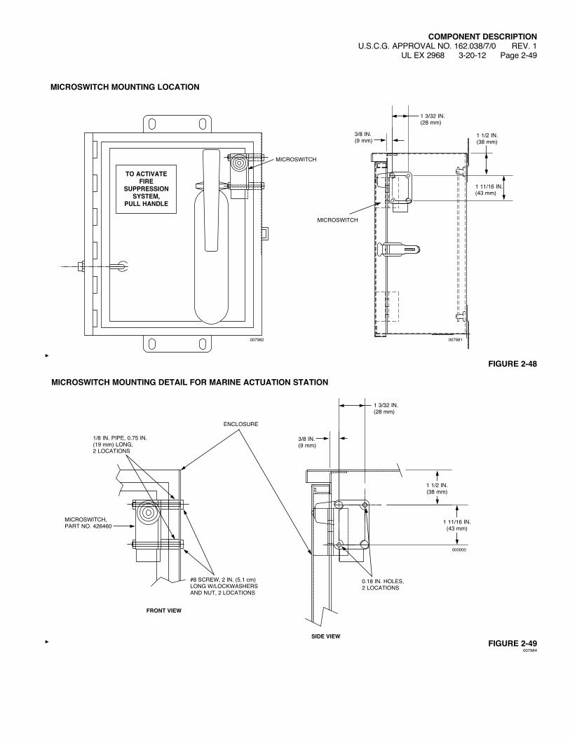
MICROSWITCH MOUNTING LOCATION
FIGURE 2-48
FIGURE 2-49007984
COMPONENT DESCRIPTIONU.S.C.G. APPROVAL NO. 162.038/7/0 REV. 1
UL EX 2968 3-20-12 Page 2-49
000000
1 3/32 IN.(28 mm)
3/8 IN.(9 mm)
1 11/16 IN.(43 mm)
1 1/2 IN.(38 mm)
0.18 IN. HOLES, 2 LOCATIONS
MICROSWITCH MOUNTING DETAIL FOR MARINE ACTUATION STATION
ENCLOSURE
MICROSWITCH,PART NO. 426460
1/8 IN. PIPE, 0.75 IN. (19 mm) LONG, 2 LOCATIONS
#8SCREW,2IN.(5.1cm) LONGW/LOCKWASHERSAND NUT, 2 LOCATIONS
SIDE VIEW
FRONT VIEW
007982
MICROSWITCH
TO ACTIVATE FIRE
SUPPRESSION SYSTEM,
PULL HANDLE
007981
MICROSWITCH
1 1/2 IN.(38 mm)
1 11/16 IN.(43 mm)
1 3/32 IN.(28 mm)
3/8 IN.(9 mm)

COMPONENT DESCRIPTIONU.S.C.G. APPROVAL NO. 162.038/7/0 REV. 1UL EX 2968 3-20-12 Page 2-50
SELECTOR VALVE PNEUMATIC ACTUATION LINE KIT (PART NO. 436127)The Selector Valve Pneumatic Actuation Line Kit is used to control the pressure in the actuation lines of the selector valves or 3/4 in. isolation valve. One Selector Valve Pneumatic Actuation Line Kit is required for each pneumatic actuator and must be installed within 1 ft (0.3 m) of the pneumatic actuator/isolation valve. The Low Pressure Vent Plug and Safety Relief Valve are to be installed with a torque of 125 in.-lb (14 Nm). After system discharge, all pressure in the actuation line must be relieved by pulling the ring on the safety relief valve.Part No. Description Material436085 Low-Pressure Vent Plug Brass15677 Safety Relief Valve Brass28484 1/4 in. Close Nipple Galvanized Steel27350 1/4 in. Tee Galvanized SteelNote: The low pressure vent plug cannot be ordered separately.
FIGURE 2-50008246
1/4 IN. TEE
LOWPRESSUREVENT PLUG
SAFETYRELIEF VALVE
1/4 IN. CLOSE NIPPLE
1 3/4 IN.(4.4 cm)
4 3/4 IN.(12.1 cm)

COMPONENT DESCRIPTIONU.S.C.G. APPROVAL NO. 162.038/7/0 REV. 1
UL EX 2968 3-20-12 Page 2-51
3/4 IN. PRESSURE ACTUATED STOP/ISOLATION VALVE (PART NO. 41702)Material: BrassThe 3/4 in. pressure actuated stop/isolation valve is used in conjunction with selector valve systems, and can be used to isolate pressure operated alarms and shut down devices.There are three methods of opening the 3/4 in. pressure actuated valve: 1. By applying pressure into the 1/8 in. NPT port located in the
rear of the valve. 2. By applying pressure at the outlet side of the valve. 3. By pulling on the manual release handle located on the front
of the valve.The 3/4 in. pressure actuated stop/isolation valve is designed to withstand a minimum burst pressure of 6000 psi (413.7 bar) and is tested to a working pressure, with carbon dioxide, of 900 psi (62.1 bar).Two 1/2 in. – 14 pipe plugs (Part No. 52056) should be ordered to complete the assembly.
FIGURE 2-51000697
MANUAL VALVERELEASE HANDLE
PIPE PLUG1/2 IN. – 14 NPT2 REQUIRED
INLET3/4 IN. – 14 NPT
OUTLET3/4 IN. – 14 NPTACTUATION
STATION INLET1/8 IN. – 27 NPT
3 9/16 IN.(9.0 cm)
5 7/8 IN.(14.9 cm)
COMPONENT DESCRIPTIONU.S.C.G. APPROVAL NO. 162.038/7/0 REV. 1UL EX 2968 3-20-12 Page 2-52
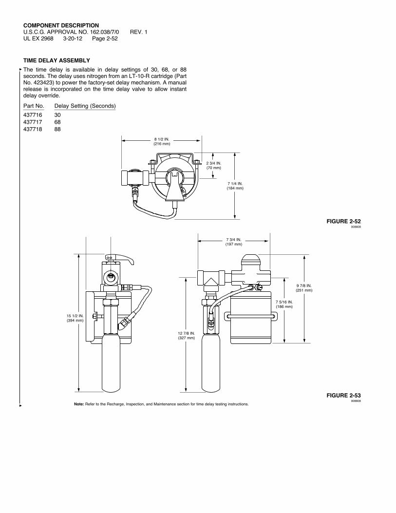
TIME DELAY ASSEMBLYThe time delay is available in delay settings of 30, 68, or 88 seconds. The delay uses nitrogen from an LT-10-R cartridge (Part No. 423423) to power the factory-set delay mechanism. A manual release is incorporated on the time delay valve to allow instant delay override.
Part No. Delay Setting (Seconds)437716 30437717 68437718 88
Note: Refer to the Recharge, Inspection, and Maintenance section for time delay testing instructions.
FIGURE 2-53008608
FIGURE 2-52008608
8 1/2 IN.(216 mm)
7 3/4 IN.(197 mm)
2 3/4 IN.(70 mm)
7 1/4 IN.(184 mm)
9 7/8 IN.(251 mm)
7 5/16 IN.(186 mm)
15 1/2 IN.(394 mm)
12 7/8 IN.(327 mm)

COMPONENT DESCRIPTIONU.S.C.G. APPROVAL NO. 162.038/7/0UL EX 2968 1-19-09 Page 2-53
STAINLESS BRAID-COVERED ACTUATION HOSE
Lengthin. (cm) Part No.16 (41) 3180920 (51) 3233524 (61) 32336This hose is used commonly in a manifolded system when piping from ‘‘master’’ valve to ‘‘slave’’ actuator, or to connect pressureactuated devices. These 3/16 in. ID hoses are constructed from Teflon tubing with a stainless steel wire braid cover. There are 7/16-20 female swivels on both ends.
FIGURE 2-54000700
3/16 IN. HOSE7/16-20FEMALESWIVEL
L
COMPONENT DESCRIPTIONU.S.C.G. APPROVAL NO. 162.038/7/0UL EX 2968 1-19-09 Page 2-54
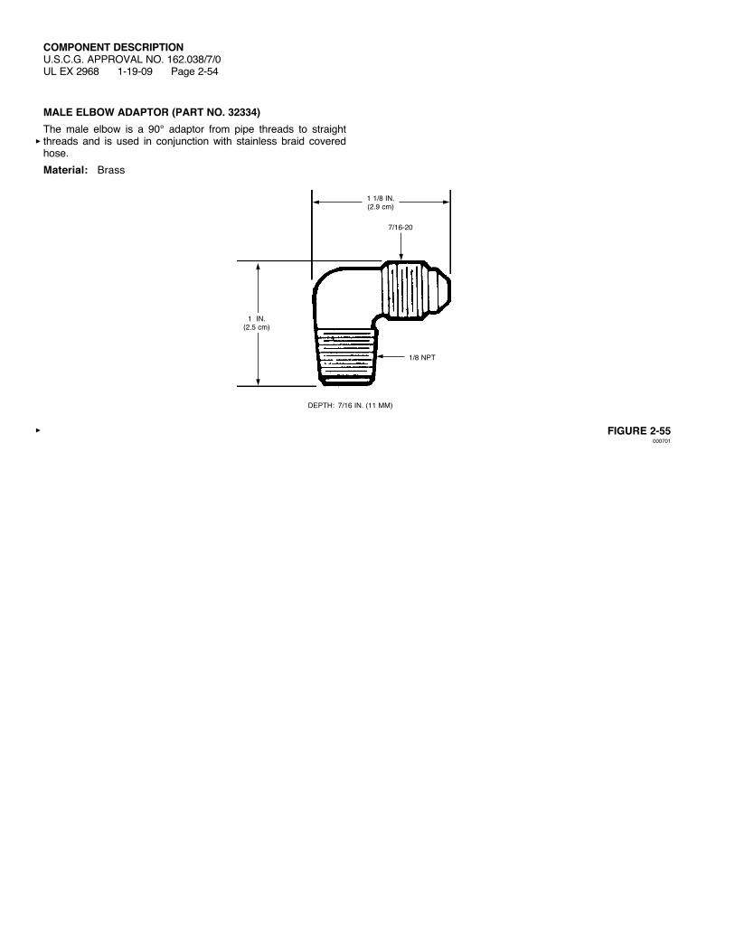
MALE ELBOW ADAPTOR (PART NO. 32334)The male elbow is a 90° adaptor from pipe threads to straight threads and is used in conjunction with stainless braid covered hose.Material: Brass
FIGURE 2-55000701
1 1/8 IN.(2.9 cm)
7/16-20
1/8 NPT
DEPTH: 7/16 IN. (11 MM)
1 IN.(2.5 cm)
COMPONENT DESCRIPTIONU.S.C.G. APPROVAL NO. 162.038/7/0UL EX 2968 1-19-09 Page 2-55
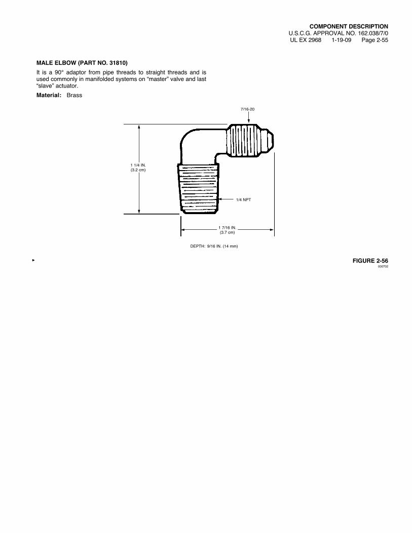
MALE ELBOW (PART NO. 31810)It is a 90° adaptor from pipe threads to straight threads and is used commonly in manifolded systems on “master” valve and last “slave” actuator.Material: Brass
FIGURE 2-56000702
1 7/16 IN.(3.7 cm)
7/16-20
1/4 NPT
DEPTH: 9/16 IN. (14 mm)
1 1/4 IN.(3.2 cm)
COMPONENT DESCRIPTIONU.S.C.G. APPROVAL NO. 162.038/7/0UL EX 2968 1-19-09 Page 2-56
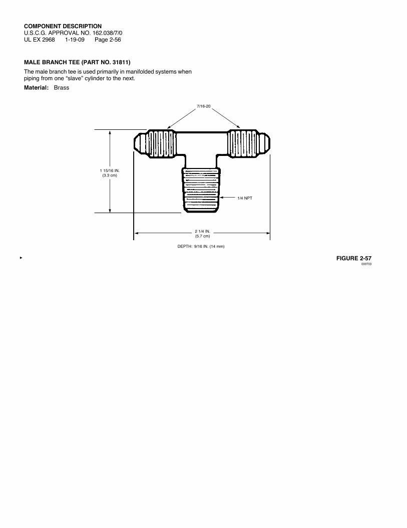
MALE BRANCH TEE (PART NO. 31811)The male branch tee is used primarily in manifolded systems when piping from one “slave” cylinder to the next.Material: Brass
FIGURE 2-57000703
2 1/4 IN.(5.7 cm)
7/16-20
1/4 NPT
DEPTH: 9/16 IN. (14 mm)
1 15/16 IN.(3.3 cm)

COMPONENT DESCRIPTIONU.S.C.G. APPROVAL NO. 162.038/7/0UL EX 2968 1-19-09 Page 2-57
MALE CONNECTOR (PART NO. 32338)This connector is used to adapt from pipe threads to straight threads, and to adapt pipe to stainless braid covered hose when it is required in a pneumatically actuated system.Material: Brass
FIGURE 2-58000704
1 1/4 IN.(3.2 cm)
7/16-20
1/4 NPT9/16 IN. HEX

COMPONENT DESCRIPTIONU.S.C.G. APPROVAL NO. 162.038/7/0UL EX 2968 1-19-09 Page 2-58
PRESSURE TRIP (PART NO. 5156)The function of the pressure trip is to set off a counterweight or spring-loaded mechanical device which closes doors or windows upon actuation of the system.Material: Brass
FIGURE 2-59000705
3 3/4 IN.(9.5 cm)
3 IN.(7.6 cm)
1/4 NPT
COMPONENT DESCRIPTIONU.S.C.G. APPROVAL NO. 162.038/7/0 REV. 1
UL EX 2968 3-20-12 Page 2-59
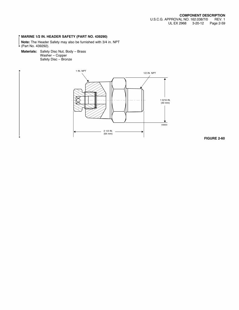
MARINE 1/2 IN. HEADER SAFETY (PART NO. 439290)Note: The Header Safety may also be furnished with 3/4 in. NPT (Part No. 439292). Materials: Safety Disc Nut, Body – Brass Washer–Copper Safety Disc – Bronze
1 9/16 IN.(40 mm)
2 1/2 IN.(64 mm)
008993
1/2 IN. NPT1 IN. NPT
FIGURE 2-60

COMPONENT DESCRIPTIONU.S.C.G. APPROVAL NO. 162.038/7/0UL EX 2968 1-19-09 Page 2-60
VENT PLUG (PART NO. 40309)Materials:Body,Stem,WasherandCheckCup–Brass Spring – Bronze Check Seal – Neoprene
FIGURE 2-61000707
7/8 IN.(22 mm)
STEMBODY
WASHER
SPRINGCHECK SEAL
CHECK CUP
1/2 NPT
29/32 IN.(23 mm)
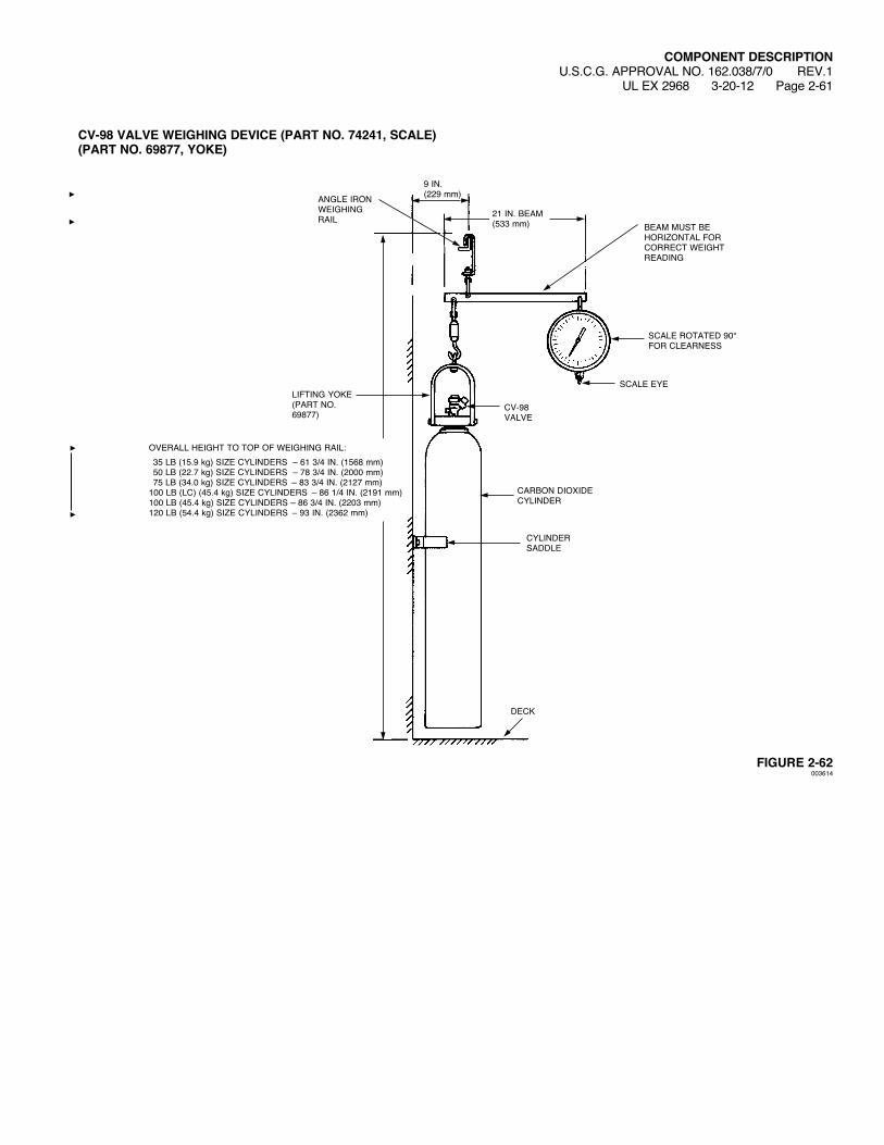
CV-98 VALVE WEIGHING DEVICE (PART NO. 74241, SCALE) (PART NO. 69877, YOKE)
FIGURE 2-62003614
COMPONENT DESCRIPTIONU.S.C.G. APPROVAL NO. 162.038/7/0 REV.1
UL EX 2968 3-20-12 Page 2-61
9 IN.(229 mm)
SCALE EYE
CARBON DIOXIDE CYLINDER
SCALE ROTATED 90° FOR CLEARNESS
BEAM MUST BEHORIZONTAL FOR CORRECTWEIGHTREADING
ANGLE IRONWEIGHINGRAIL
LIFTING YOKE (PART NO. 69877)
CYLINDERSADDLE
DECK
CV-98 VALVE
21 IN. BEAM(533 mm)
OVERALLHEIGHTTOTOPOFWEIGHINGRAIL: 35 LB (15.9 kg) SIZE CYLINDERS – 61 3/4 IN. (1568 mm) 50 LB (22.7 kg) SIZE CYLINDERS – 78 3/4 IN. (2000 mm) 75 LB (34.0 kg) SIZE CYLINDERS – 83 3/4 IN. (2127 mm)100 LB (LC) (45.4 kg) SIZE CYLINDERS – 86 1/4 IN. (2191 mm)100 LB (45.4 kg) SIZE CYLINDERS – 86 3/4 IN. (2203 mm)120 LB (54.4 kg) SIZE CYLINDERS – 93 IN. (2362 mm)
COMPONENT DESCRIPTIONU.S.C.G. APPROVAL NO. 162.038/7/0UL EX 2968 1-19-09 Page 2-62
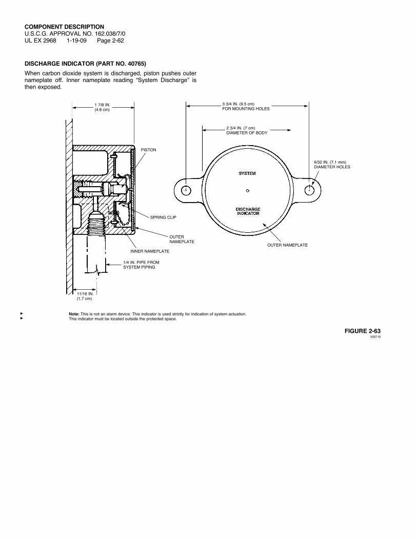
DISCHARGE INDICATOR (PART NO. 40765)Whencarbondioxidesystemisdischarged,pistonpushesouternameplate off. Inner nameplate reading “System Discharge” is then exposed.
FIGURE 2-63000710
Note: This is not an alarm device. This indicator is used strictly for indication of system actuation.This indicator must be located outside the protected space.
OUTER NAMEPLATE
OUTER NAMEPLATE
1/4 IN. PIPE FROM SYSTEM PIPING
PISTON
SPRING CLIP
INNER NAMEPLATE
11/16 IN.(1.7 cm)
9/32 IN. (7.1 mm) DIAMETER HOLES
1 7/8 IN.(4.8 cm)
3 3/4 IN. (9.5 cm)FOR MOUNTING HOLES
2 3/4 IN. (7 cm)DIAMETER OF BODY
COMPONENT DESCRIPTIONU.S.C.G. APPROVAL NO. 162.038/7/0UL EX 2968 1-19-09 Page 2-63
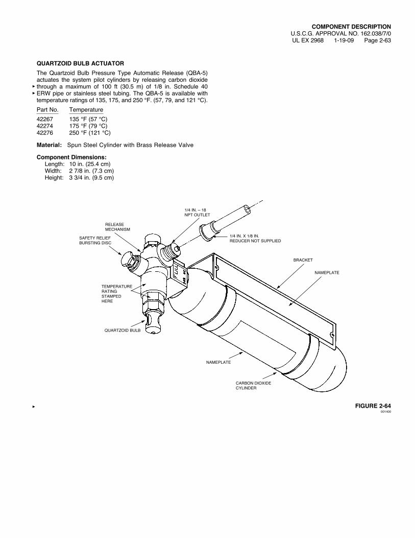
QUARTZOID BULB ACTUATORThe Quartzoid Bulb Pressure Type Automatic Release (QBA-5) actuates the system pilot cylinders by releasing carbon dioxide through a maximum of 100 ft (30.5 m) of 1/8 in. Schedule 40 ERWpipeorstainlesssteel tubing.TheQBA-5 isavailablewithtemperature ratings of 135, 175, and 250 °F. (57, 79, and 121 °C).Part No. Temperature42267 135 °F (57 °C)42274 175 °F (79 °C)42276 250 °F (121 °C)
Material: Spun Steel Cylinder with Brass Release Valve
Component Dimensions: Length: 10 in. (25.4 cm) Width: 27/8in.(7.3cm) Height: 3 3/4 in. (9.5 cm)
FIGURE 2-64001400
RELEASEMECHANISM
SAFETY RELIEFBURSTING DISC
TEMPERATURERATING STAMPEDHERE
QUARTZOID BULB
1/4 IN. – 18 NPT OUTLET
1/4 IN. X 1/8 IN.REDUCER NOT SUPPLIED
BRACKET
NAMEPLATE
NAMEPLATE
CARBON DIOXIDECYLINDER

COMPONENT DESCRIPTIONU.S.C.G. APPROVAL NO. 162.038/7/0 REV. 3UL EX 2968 7-14-14 Page 2-64
PRESSURE-OPERATED SIREN (PART NO. 437616)The pressure-operated siren is used to warn personnel of a system discharge. The siren is operated with the carbon dioxide pressure from the pilot cylinder. The siren will operate at the start of the system actuation and will continue through most of the discharge time. A pipe hanger or bracket must be installed within one foot of the siren.
ComponentSiren
MaterialBody: BrassGrill: SteelScreen: Stainless Steel
Specifications Maximum Pipe Length: – 240 ft (73.2 m) of 3/4 in. Schedule 40 pipe – 430 ft (131.1 m) of 1/2 in. Schedule 40 pipe – 675 ft (205.7 m) of 3/8 in. Schedule 40 pipe Maximum Elbows: 30 Maximum Sirens: 5
ShippingAssemblyPart No. Description437616 Pressure-Operated Siren
FIGURE 2-65008806
1/4 IN.NPT INLET
6.25 IN.(159 mm)
0.34 IN. (9 mm) DIA. HOLE (2)
5.25 IN.(133 mm)
5.60 IN.(142 mm)
3.42 IN.(87 mm)
COMPONENT DESCRIPTIONU.S.C.G. APPROVAL NO. 162.038/7/0 REV. 1
UL EX 2968 6-12-12 Page 2-65
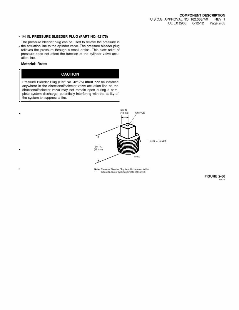
1/4 IN. PRESSURE BLEEDER PLUG (PART NO. 42175)The pressure bleeder plug can be used to relieve the pressure in the actuation line to the cylinder valve. The pressure bleeder plug relieves the pressure through a small orifice. This slow relief of pressure does not affect the function of the cylinder valve actu-ation line.
Material: Brass
CAUTION
Pressure Bleeder Plug (Part No. 42175) must not be installed anywhere in the directional/selector valve actuation line as the directional/selector valve may not remain open during a com-plete system discharge, potentially interfering with the ability of the system to suppress a fire.
FIGURE 2-66000714
ORIFICE3/8 IN.(10 mm)
1/4 IN. – 18 NPT
001839
3/4 IN.(19 mm)
Note: Pressure Bleeder Plug is not to be used in the actuation line of selector/directional valves.

COMPONENT DESCRIPTIONU.S.C.G. APPROVAL NO. 162.038/7/0 REV. 1UL EX 2968 6-12-12 Page 2-66
PRESSURE SWITCH – 3PDT (PART NO. 437900)The pressure switch is operated by the carbon dioxide agent pres-sure when the system is discharged. The pressure switch can be used to open or close electrical circuits to shut down equipment (single or 3-phase) or turn on lights or alarms. The housing is constructed of 16 ga. steel, painted red, and is rated IP65 for dust and water ingress. The 3/8 in. NPT brass pressure inlet is used to connect the pressure switch to the suppression system.Minimum operating pressure is 50 psi (3.5 bar). Thread Size/ ElectricalComponent Material Type RatingPressure Switch: Conduit Inlets: 10A, 250 VAC Switch – Nickel-plated 3/4 in. and 1/2 in. 15A, 125 VAC 3PDT Brass Housing/Cover: Pressure Inlet: 3/4 HP, C.R. 16 ga steel 3/8 in. NPT 250 VAC Plunger: Female 1-, 2-, and Stainless Steel 3-phase Pressure Port: C37700 Brass
FIGURE 2-67
008979
6.0 IN.(152 mm)
4.45 IN.(113 mm)
2.75 IN.(70 mm)
5.25 IN.(133 mm)
0089783.83 IN.(97 mm)
4.45 IN.(113 mm)
4.51 IN.(115 mm)

COMPONENT DESCRIPTIONU.S.C.G. APPROVAL NO. 162.038/7/0 REV. 1
UL EX 2968 6-12-12 Page 2-67
PAGE INTENTIONALLY LEFT BLANK

COMPONENT DESCRIPTIONU.S.C.G. APPROVAL NO. 162.038/7/0 REV. 1UL EX 2968 6-12-12 Page 2-68
PAGE INTENTIONALLY LEFT BLANK
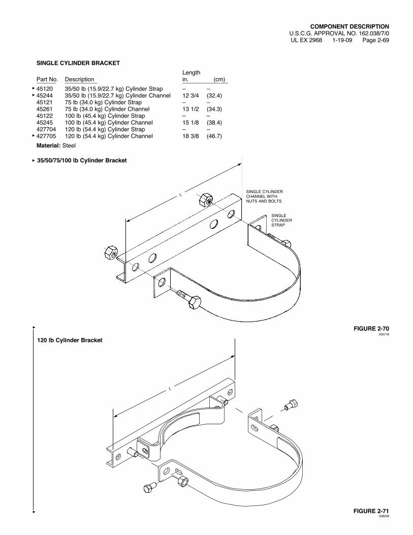
SINGLE CYLINDER BRACKET LengthPart No. Description in. (cm)______ __________ ______________45120 35/50 lb (15.9/22.7 kg) Cylinder Strap – –45244 35/50 lb (15.9/22.7 kg) Cylinder Channel 12 3/4 (32.4)45121 75 lb (34.0 kg) Cylinder Strap – –45261 75 lb (34.0 kg) Cylinder Channel 13 1/2 (34.3)45122 100 lb (45.4 kg) Cylinder Strap – –45245 100 lb (45.4 kg) Cylinder Channel 15 1/8 (38.4)427704 120 lb (54.4 kg) Cylinder Strap – –427705 120 lb (54.4 kg) Cylinder Channel 18 3/8 (46.7)Material: Steel
FIGURE 2-70000718
FIGURE 2-71008206
COMPONENT DESCRIPTIONU.S.C.G. APPROVAL NO. 162.038/7/0UL EX 2968 1-19-09 Page 2-69
SINGLECYLINDERSTRAP
SINGLE CYLINDERCHANNELWITHNUTS AND BOLTS
35/50/75/100 lb Cylinder Bracket
L
120 lb Cylinder Bracket
L
COMPONENT DESCRIPTIONU.S.C.G. APPROVAL NO. 162.038/7/0UL EX 2968 1-19-09 Page 2-70
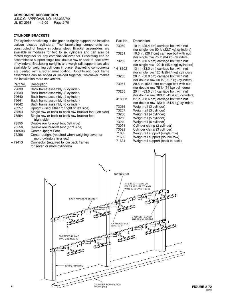
CYLINDER BRACKETSThe cylinder bracketing is designed to rigidly support the installed carbon dioxide cylinders. The bracketing components are constructed of heavy structural steel. Bracket assemblies are available in modules for two to six cylinders and can also be mated together for any combination over six. Bracketing can be assembled to support single row, double row or back-to-back rows of cylinders. Bracketing uprights and weigh rail supports are also available for weighing cylinders in place. Bracketing components are painted with a red enamel coating. Uprights and back frame assemblies can be bolted or welded together, whichever makes the installation more convenient.Part No. Description79638 Back frame assembly (2 cylinder)79639 Back frame assembly (3 cylinder)79640 Back frame assembly (4 cylinder)79641 Back frame assembly (5 cylinder)79642 Back frame assembly (6 cylinder)73257 Upright (used either for right or left side)73553 Single row or back-to-back row bracket foot (left side)73554 Single row or back-to-back row bracket foot (right side)73555 Double row bracket foot (left side)73556 Double row bracket foot (right side)418508 Center Upright Foot73256 Center upright (required when weighing seven or
more cylinders in a row)79413 Connector (required to join back frames
for seven or more cylinders)
Part No. Description73250 10 in. (25.4 cm) carriage bolt with nut
(for single row 50 lb (22.7 kg) cylinders)73251 10.5 in. (26.7 cm) carriage bolt with nut
(for single row 75 lb (34 kg) cylinders)73252 12 in. (30.5 cm) carriage bolt with nut
(for single row 100 lb (45.4 kg) cylinders)418502 13 in. (33.0 cm) carriage bolt with nut
(for single row 120 lb (54.4 kg) cylinders73253 20 in. (50.8 cm) carriage bolt with nut
(for double row 50 lb (22.7 kg) cylinders)73254 20.5 in. (52.1 cm) carriage bolt with nut
(for double row 75 lb (34 kg) cylinders)73255 25 in. (63.5 cm) carriage bolt with nut
(for double row 100 lb (45.4 kg) cylinders)418503 27 in. (68.6 cm) carriage bolt with nut
(for double row 120 lb (54.4 kg) cylinders73266 Weighrail(2cylinder)73267 Weighrail(3cylinder)73268 Weighrail(4cylinder)73269 Weighrail(5cylinder)73270 Weighrail(6cylinder)73091 Cylinder clamp (2 cylinder)73092 Cylinder clamp (3 cylinder)71683 Weighrailsupport(singlerow)71682 Weighrailsupport(doublerow)71684 Weighrailsupport(backtoback)
FIGURE 2-72000719
CONNECTOR
BACK FRAME ASSEMBLY
CYLINDER FOUNDATION BY OTHERS
CYLINDER CLAMPTWOCYLINDERS
CYLINDER CLAMPTHREE CYLINDERS
7/16 IN. X 1 1/2 IN. LG. BOLTSWITHNUTSANDWASHERSBYOTHERS
CARRIAGE BOLT WITHNUT
SHIPS FRAMING
COMPONENT DESCRIPTIONU.S.C.G. APPROVAL NO. 162.038/7/0 REV. 1
UL EX 2968 6-12-12 Page 2-71
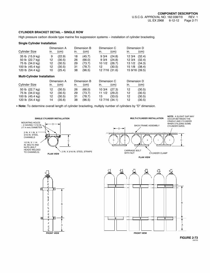
CYLINDER BRACKET DETAIL – SINGLE ROWHigh pressure carbon dioxide type marine fire suppression systems – installation of cylinder bracketing.
Single Cylinder Installation Dimension A Dimension B Dimension C Dimension DCylinder Size in. (cm) in. (cm) in. (cm) in. (cm) 35 lb (15.9 kg) 9 (22.9) 18 (45.7) 9 3/4 (24.8) 12 3/4 (32.4) 50 lb (22.7 kg) 12 (30.5) 26 (66.0) 9 3/4 (24.8) 12 3/4 (32.4) 75 lb (34.0 kg) 12 (30.5) 29 (73.7) 10 1/2 (26.7) 13 1/2 (34.3)100 lb (45.4 kg) 12 (30.5) 31 (78.7) 12 (30.5) 15 1/8 (38.4)120 lb (54.4 kg) 10 (25.4) 38 (96.5) 12 7/16 (31.6) 15 9/16 (39.5)
Multi-Cylinder Installation Dimension A Dimension B Dimension C Dimension DCylinder Size in. (cm) in. (cm) in. (cm) in. (cm) 50 lb (22.7 kg) 12 (30.5) 26 (66.0) 10 3/4 (27.3) 12 (30.5) 75 lb (34.0 kg) 12 (30.5) 29 (73.7) 11 1/2 (29.2) 12 (30.5)100 lb (45.4 kg) 12 (30.5) 31 (78.7) 13 (33.0) 12 (30.5)120 lb (54.4 kg) 14 (35.6) 38 (96.5) 13 7/16 (34.1) 12 (30.5)
Note: To determine overall length of cylinder bracketing, multiply number of cylinders by “D” dimension.
FIGURE 2-73000720
D
C
MULTI-CYLINDER INSTALLATION
FRONT VIEW
BACK FRAME ASSEMBLY
CYLINDER CLAMPCARRIAGE BOLT WITHNUT
NOTE: A SLIGHT GAP MAY OCCURBETWEENTHECRADLE AND CYLINDER WHENUTILIZINGSOMECYLINDER SIZES.
A
B
PLAN VIEW
D
C
SINGLE CYLINDER INSTALLATION
PLAN VIEW
MOUNTING HOLES – 2 HAVING 11/16 IN. (17.4 mm) DIAMETER
2 IN. X 3/16 IN. STEEL STRAPS
1/2 IN. X 1 1/4 IN. BOLTS AND NUTS (BOLT HEADSWELDEDTO CHANNELS)
2 IN. X 1 IN. X 3/16 IN. STEEL CHANNELS
A
FRONT VIEW
B
COMPONENT DESCRIPTIONU.S.C.G. APPROVAL NO. 162.038/7/0UL EX 2968 1-19-09 Page 2-72
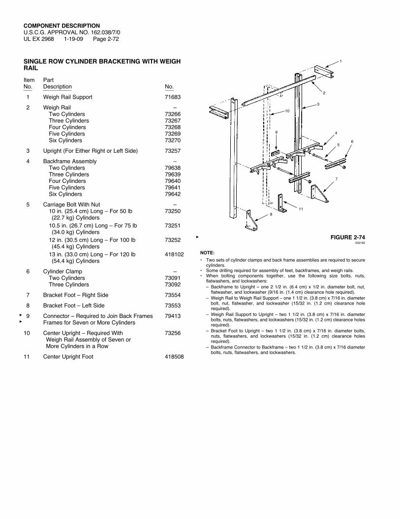
SINGLE ROW CYLINDER BRACKETING WITH WEIGH RAIL
Item PartNo. Description No.
1 WeighRailSupport 71683
2 WeighRail – Two Cylinders 73266 Three Cylinders 73267 Four Cylinders 73268 Five Cylinders 73269 Six Cylinders 73270
3 Upright (For Either Right or Left Side) 73257
4 Backframe Assembly – Two Cylinders 79638 Three Cylinders 79639 Four Cylinders 79640 Five Cylinders 79641 Six Cylinders 79642
5 CarriageBoltWithNut – 10 in. (25.4 cm) Long – For 50 lb 73250 (22.7 kg) Cylinders 10.5 in. (26.7 cm) Long – For 75 lb 73251 (34.0 kg) Cylinders 12 in. (30.5 cm) Long – For 100 lb 73252 (45.4 kg) Cylinders 13 in. (33.0 cm) Long – For 120 lb 418102 (54.4 kg) Cylinders
6 Cylinder Clamp – Two Cylinders 73091 Three Cylinders 73092
7 Bracket Foot – Right Side 73554
8 Bracket Foot – Left Side 73553
9 Connector – Required to Join Back Frames 79413 Frames for Seven or More Cylinders
10 CenterUpright–RequiredWith 73256 WeighRailAssemblyofSevenor More Cylinders in a Row
11 Center Upright Foot 418508
FIGURE 2-74002182
NOTE:• Two sets of cylinder clamps and back frame assemblies are required to secure
cylinders.• Some drilling required for assembly of feet, backframes, and weigh rails.• When bolting components together, use the following size bolts, nuts,
flatwashers, and lockwashers: – Backframe to Upright – one 2 1/2 in. (6.4 cm) x 1/2 in. diameter bolt, nut,
flatwasher, and lockwasher (9/16 in. (1.4 cm) clearance hole required). – WeighRailtoWeighRailSupport–one11/2in.(3.8cm)x7/16in.diameter
bolt, nut, flatwasher, and lockwasher (15/32 in. (1.2 cm) clearance hole required).
– WeighRailSupport toUpright– two11/2 in. (3.8cm)x7/16 in.diameterbolts, nuts, flatwashers, and lockwashers (15/32 in. (1.2 cm) clearance holes required).
– Bracket Foot to Upright – two 1 1/2 in. (3.8 cm) x 7/16 in. diameter bolts, nuts, flatwashers, and lockwashers (15/32 in. (1.2 cm) clearance holes required).
– Backframe Connector to Backframe – two 1 1/2 in. (3.8 cm) x 7/16 dia meter bolts, nuts, flatwashers, and lockwashers.
10
1
3
2
4
56
7
8
9
11

COMPONENT DESCRIPTIONU.S.C.G. APPROVAL NO. 162.038/7/0 REV. 1
UL EX 2968 6-12-12 Page 2-73
CYLINDER BRACKET DETAIL – DOUBLE ROW
Dimension A Dimension B Dimension C Dimension DCylinder Size in. (cm) in. (cm) in. (cm) in. (cm) 50 lb (22.7 kg) 12 (30.5) 20 1/2 (52.1) 12 (30.5) 26 (66.0) 75 lb (34.0 kg) 12 (30.5) 22 (55.9) 12 (30.5) 29 (73.7)100 lb (45.4 kg) 12 (30.5) 25 (63.5) 12 (30.5) 31 (78.7)120 lb (54.4 kg) 12 (30.5) 26 (66.0) 14 (35.6) 38 (96.5)
Note: To determine overall length of cylinder bracketing, multiply number of cylinders by “B” dimension.
FIGURE 2-75000721
BACK FRAME ASSEMBLY
CYLINDER CLAMP
CYLINDER BRACKET DETAIL – DOUBLE ROW
A
B
D
C
NOTE: A SLIGHT GAP MAY OCCURBETWEENTHECRADLE AND CYLINDER WHENUTILIZINGSOMECYLINDER SIZES.

COMPONENT DESCRIPTIONU.S.C.G. APPROVAL NO. 162.038/7/0UL EX 2968 1-19-09 Page 2-74
DOUBLE ROW CYLINDER BRACKETING WITH WEIGH RAIL
Item PartNo. Description No.
1 WeighRailSupport 71682
2 WeighRail – Two Cylinders 73266 Three Cylinders 73267 Four Cylinders 73268 Five Cylinders 73269 Six Cylinders 73270
3 Upright (For Either Right or Left Side) 73257
4 Backframe Assembly – Two Cylinders 79638 Three Cylinders 79639 Four Cylinders 79640 Five Cylinders 79641 Six Cylinders 79642
5 CarriageBoltWithNut – 20 in. (50.8 cm) Long – For 50 lb 73253 (22.7 kg) Cylinders 20.5 in. (52.1 cm) Long – For 75 lb 73254 (34.0 kg) Cylinders 25 in. (63.5 cm) Long – For 100 lb 73255 (45.4 kg) Cylinders 27 in. (68.6 cm) Long – For 120 lb 418503 (54.4 kg) Cylinders
6 Cylinder Clamp – Two Cylinders 73091 Three Cylinders 73092
7 Bracket Foot – Right Side 73556
8 Bracket Foot – Left Side 73555
9 Connector – Required to Join Back Frames 79413 for Seven or More Cylinders
10 CenterUpright–RequiredWith 73256 WeighRailAssemblyofSevenor More Cylinders in a Row
11 Center Upright Foot 418508
FIGURE 2-76002183
NOTE:• Two sets of cylinder clamps and back frame assemblies are required to secure
cylinders.• Some drilling required for assembly of feet, backframes, and weigh rails.• When bolting components together, use the following size bolts, nuts,
flatwashers, and lockwashers: – Backframe to Upright – one 2 1/2 in. (6.4 cm) x 1/2 in. diameter bolt, nut,
flatwasher, and lockwasher (9/16 in. (1.4 cm) clearance hole required). – WeighRailtoWeighRailSupport–one11/2in.(3.8cm)x7/16in.diameter
bolt, nut, flatwasher, and lockwasher (15/32 in. (1.2 cm) clearance hole required).
– WeighRailSupport toUpright– two11/2 in. (3.8cm)x7/16 in.diameterbolts, nuts, flatwashers, and lockwashers (15/32 in. (1.2 cm) clearance holes required).
– Bracket Foot to Upright – two 1 1/2 in. (3.8 cm) x 7/16 in. diameter bolts, nuts, flatwashers, and lockwashers (15/32 in. (1.2 cm) clearance holes required).
– Backframe Connector to Backframe – two 1 1/2 in. (3.8 cm) x 7/16 dia meter bolts, nuts, flatwashers, and lockwashers.
10
1
3
2
4
56
7
8
9
11
COMPONENT DESCRIPTIONU.S.C.G. APPROVAL NO. 162.038/7/0 REV. 1
UL EX 2968 6-12-12 Page 2-75
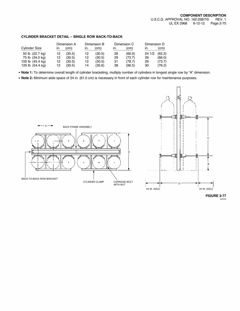
CYLINDER BRACKET DETAIL – SINGLE ROW BACK-TO-BACK
Dimension A Dimension B Dimension C Dimension DCylinder Size in. (cm) in. (cm) in. (cm) in. (cm) 50 lb (22.7 kg) 12 (30.5) 12 (30.5) 26 (66.0) 24 1/2 (62.2) 75 lb (34.0 kg) 12 (30.5) 12 (30.5) 29 (73.7) 26 (66.0)100 lb (45.4 kg) 12 (30.5) 12 (30.5) 31 (78.7) 29 (73.7)120 lb (54.4 kg) 12 (30.5) 14 (35.6) 38 (96.5) 30 (76.2)
Note 1: To determine overall length of cylinder bracketing, multiply number of cylinders in longest single row by “A” dimension.Note 2: Minimum aisle space of 24 in. (61.0 cm) is necessary in front of each cylinder row for maintenance purposes.
FIGURE 2-77000722
BACK FRAME ASSEMBLY
CARRIAGE BOLT WITHNUT
24 IN. AISLE 24 IN. AISLE
CYLINDER CLAMPBACK-TO-BACKROWBRACKET
A
D
D
C
B

COMPONENT DESCRIPTIONU.S.C.G. APPROVAL NO. 162.038/7/0UL EX 2968 1-19-09 Page 2-76
BACK-TO-BACK CYLINDER BRACKETING WITH WEIGH RAIL
Item PartNo. Description No.
1 WeighRailSupport 71684
2 WeighRail – Two Cylinders 73266 Three Cylinders 73267 Four Cylinders 73268 Five Cylinders 73269 Six Cylinders 73270
3 Upright (For Either Right or Left Side) 73257
4 Backframe Assembly – Two Cylinders 79638 Three Cylinders 79639 Four Cylinders 79640 Five Cylinders 79641 Six Cylinders 79642
5 CarriageBoltWithNut – 10 in. (25.4 cm) Long – For 50 lb 73250 (22.7 kg) Cylinders 10.5 in. (26.7 cm) Long – For 75 lb 73251 (34.0 kg) Cylinders 12 in. (30.5 cm) Long – For 100 lb 73252 (45.4 kg) Cylinders 13 in. (33.0 cm) Long – For 120 lb 418102 (54.4 kg) Cylinders
6 Cylinder Clamp – Two Cylinders 73091 Three Cylinders 73092
7 Bracket Foot – Right Side 73554
8 Bracket Foot – Left Side 73553
9 Connector – Required to Join Back Frames 79413 for Seven or More Cylinders
10 CenterUpright–RequiredWith 73256 WeighRailAssemblyofSevenor More Cylinders in a Row
11 Center Upright Foot 418508
FIGURE 2-78002184
NOTE:• Two sets of cylinder clamps and back frame assemblies are required to secure
cylinders.• Some drilling required for assembly of feet, backframes, and weigh rails.• When bolting components together, use the following size bolts, nuts,
flatwashers, and lockwashers: – Backframe to Upright – one 2 1/2 in. (6.4 cm) x 1/2 in. diameter bolt, nut,
flatwasher, and lockwasher (9/16 in. (1.4 cm) clearance hole required). – WeighRailtoWeighRailSupport–one11/2in.(3.8cm)x7/16in.diameter
bolt, nut, flatwasher, and lockwasher (15/32 in. (1.2 cm) clearance hole required).
– WeighRailSupport toUpright– two11/2 in. (3.8cm)x7/16 in.diameterbolts, nuts, flatwashers, and lockwashers (15/32 in. (1.2 cm) clearance holes required).
– Bracket Foot to Upright – two 1 1/2 in. (3.8 cm) x 7/16 in. diameter bolts, nuts, flatwashers, and lockwashers (15/32 in. (1.2 cm) clearance holes required).
– Backframe Connector to Backframe – two 1 1/2 in. (3.8 cm) x 7/16 dia meter bolts, nuts, flatwashers, and lockwashers.
10
1
3
2
4
5 6
7
8
9
11

COMPONENT DESCRIPTIONU.S.C.G. APPROVAL NO. 162.038/7/0UL EX 2968 1-19-09 Page 2-77
NAMEPLATE (PART NO. 41907, BLANK) (PART NO. 41908, ENGRAVED)
FIGURE 2-79000723
2 1/8 IN.(5.4 cm)
#7 (0.2 IN.) DR. 4 HOLES
5/16 IN.(8 mm)
2 3/4 IN.(7 cm)
6 1/4 IN.(15.9 cm)
5 5/8 IN.(14.3 cm)
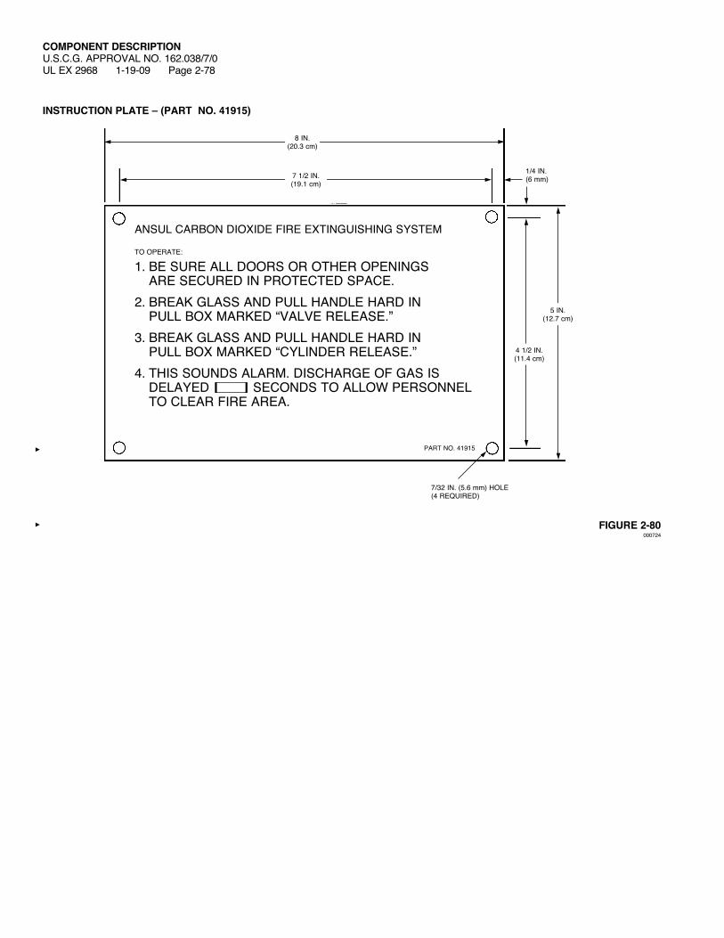
COMPONENT DESCRIPTIONU.S.C.G. APPROVAL NO. 162.038/7/0UL EX 2968 1-19-09 Page 2-78
INSTRUCTION PLATE – (PART NO. 41915)
FIGURE 2-80000724
5 IN.(12.7 cm)
7/32 IN. (5.6 mm) HOLE(4 REQUIRED)
PART NO. 41915
1/4 IN.(6 mm)
4 1/2 IN.(11.4 cm)
8 IN.(20.3 cm)
7 1/2 IN.(19.1 cm)
ANSUL CARBON DIOXIDE FIRE EXTINGUISHING SYSTEM
TO OPERATE:
1. BE SURE ALL DOORS OR OTHER OPENINGS ARE SECURED IN PROTECTED SPACE.
2. BREAK GLASS AND PULL HANDLE HARD IN PULL BOX MARKED “VALVE RELEASE.”
3. BREAK GLASS AND PULL HANDLE HARD IN PULL BOX MARKED “CYLINDER RELEASE.”
4. THIS SOUNDS ALARM. DISCHARGE OF GAS IS DELAYED □SECONDSTOALLOWPERSONNELTO CLEAR FIRE AREA.

COMPONENT DESCRIPTIONU.S.C.G. APPROVAL NO. 162.038/7/0UL EX 2968 1-19-09 Page 2-79
MAINTENANCE PLATE – PART NO. 41917
FIGURE 2-81000725
4 7/8 IN.(12.4 cm)
5/32 IN. (4.0 mm) HOLE(4 REQUIRED)
ANSUL INCORPORATEDONE STANTON STREETMARINETTE,WI54143-2542715-735-7411
ANSUL®LABEL NO. 41917
3/16 IN.(5 mm)
4 1/2 IN.(11.4 cm)
5 3/4 IN.(14.6 cm)
5 3/8 IN.(13.7 cm)
ANSUL CARBON DIOXIDE FIRE SUPPRESSION SYSTEMCYLINDER VALVESMAINTENANCE INSTRUCTIONS
WEIGH CYLINDERS EVERY SIX MONTHS AND RECORDON CYLINDER RECORD TAG. IF WEIGHT OF CYLINDERIS LBS. ( KG) LESS THAN FULLWEIGHTSTAMPED ON THE BODY OF CYLINDER VALVE OR ON NECK OF CYLINDER, RECHARGE. WHEN SHIPPING CYLINDER, BESURETHATCAPISSCREWEDONTOPOFCYLINDER.BEFOREWEIGHING CYLINDERS, REMOVE RELEASE ATTACHMENTSFROM THE CONTROL CYLINDERS AND DISCONNECT THE FLEXIBLE DISCHARGE BEND FROM ALL CYLINDERS BEING WEIGHED. BE SURE THAT RELEASE ATTACHMENT IS IN SETPOSITIONWHENREPLACINGVALVE.CARBON DIOXIDE GAS HMIS 1-0-0/VERY COLD DISCHARGE. CONTENTS UNDER HIGH PRESSURE.FOR DETAILS SEE INSTRUCTION BOOK.

COMPONENT DESCRIPTIONU.S.C.G. APPROVAL NO. 162.038/7/0UL EX 2968 1-19-09 Page 2-80
WARNING SIGNSThe following warning plates are required either inside or outside the hazard area to warn personnel that the space is protected by a carbon dioxide system and no one should enter after a discharge without being properly protected. The warning plates are furnished with four mounting holes for ease of installation.Mounting Hole Size: 7/32 in. (0.56 cm)
FIGURE 2-82
Part No. 425309 Sign In Every Protected Area
Part No. 425311 Sign In Every Nearby Space Where CO2 Can Accumulate to Hazardous Levels
Part No. 425310 Sign at Every Entrance to Protected Space
Part No. 425312 Sign at Each Manual Actuation Station
Part No. 433625 Sign at Every Entrance to Protected Space for Systems Provided with Odorizer
Part No. 433626 Sign Outside Each Entrance to CO2 Storage Room
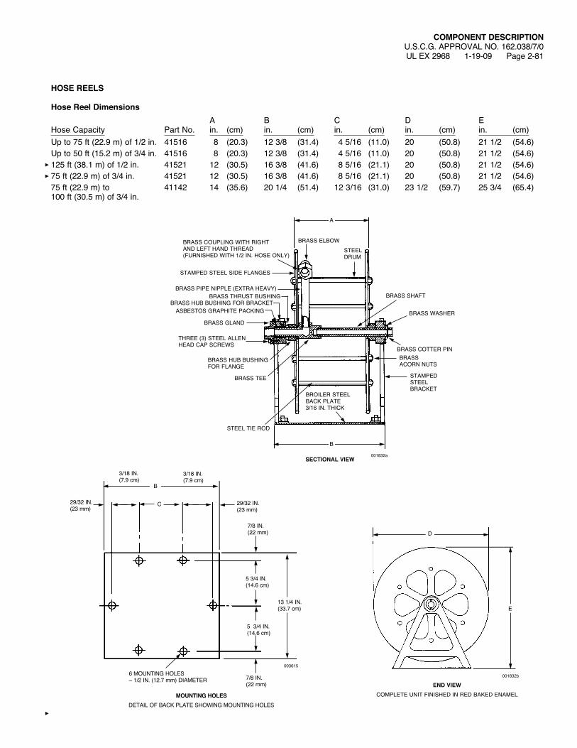
COMPONENT DESCRIPTIONU.S.C.G. APPROVAL NO. 162.038/7/0UL EX 2968 1-19-09 Page 2-81
HOSE REELS
Hose Reel Dimensions A B C D EHose Capacity Part No. in. (cm) in. (cm) in. (cm) in. (cm) in. (cm)Up to 75 ft (22.9 m) of 1/2 in. 41516 8 (20.3) 12 3/8 (31.4) 4 5/16 (11.0) 20 (50.8) 21 1/2 (54.6)Up to 50 ft (15.2 m) of 3/4 in. 41516 8 (20.3) 12 3/8 (31.4) 4 5/16 (11.0) 20 (50.8) 21 1/2 (54.6)125 ft (38.1 m) of 1/2 in. 41521 12 (30.5) 16 3/8 (41.6) 8 5/16 (21.1) 20 (50.8) 21 1/2 (54.6)75 ft (22.9 m) of 3/4 in. 41521 12 (30.5) 16 3/8 (41.6) 8 5/16 (21.1) 20 (50.8) 21 1/2 (54.6)75 ft (22.9 m) to 41142 14 (35.6) 20 1/4 (51.4) 12 3/16 (31.0) 23 1/2 (59.7) 25 3/4 (65.4) 100 ft (30.5 m) of 3/4 in.
D
E
001832b
END VIEWCOMPLETE UNIT FINISHED IN RED BAKED ENAMEL
STEEL DRUM
BRASSELBOWBRASSCOUPLINGWITHRIGHT AND LEFT HAND THREAD (FURNISHEDWITH1/2IN.HOSEONLY)
STAMPED STEEL SIDE FLANGES
BRASS PIPE NIPPLE (EXTRA HEAVY)BRASS THRUST BUSHING
BRASS HUB BUSHING FOR BRACKETASBESTOS GRAPHITE PACKING
BRASS GLAND
A
B
THREE (3) STEEL ALLEN HEADCAPSCREWS
BRASS HUB BUSHING FOR FLANGE
BRASS TEE
STEEL TIE ROD
BROILER STEEL BACK PLATE3/16 IN. THICK
BRASS SHAFT
BRASSWASHER
BRASS COTTER PINBRASS ACORN NUTS
STAMPED STEEL BRACKET
001832aSECTIONAL VIEW
13 1/4 IN.(33.7 cm)
7/8 IN.(22 mm)
5 3/4 IN.(14.6 cm)
7/8 IN.(22 mm)
3/18 IN.(7.9 cm)
29/32 IN.(23 mm)
29/32 IN.(23 mm)
C
3/18 IN.(7.9 cm)
5 3/4 IN.(14.6 cm)
6 MOUNTING HOLES– 1/2 IN. (12.7 mm) DIAMETER
MOUNTING HOLESDETAILOFBACKPLATESHOWINGMOUNTINGHOLES
003615
B

COMPONENT DESCRIPTIONU.S.C.G. APPROVAL NO. 162.038/7/0 REV. 1UL EX 2968 6-12-12 Page 2-82
FIGURE 2-83
1/2 IN. HOSE AND REELS WITH HOSEExtra heavy flexible hose – wire reinforced high pressure type – 1/2 in. (2.5 cm) size.Note: Minimum bursting pressure 6000 psi (413.7 bar) ends are die pressed male and female NPT threaded brass couplings.
Reel And Hose AssembliesSize Part No.Reel with 50 ft (15.2 m) of 1/2 in. Hose 41519Reel with 75 ft (22.9 m) of 1/2 in. Hose 41520Reel with 100 ft (30.5 m) of 1/2 in. Hose 41523
Hose LengthSize Part No.25 ft (7.6 m) 4222750 ft (15.2 m) 42228
FIGURE 2-84001843
NEOPRENE COVER – WINTERIZED–40°F(–40 °C)
WIREBRAID
FRICTION JACKET
FRICTION JACKET
WIREBRAID
SYNTHETIC RUBBER INNER TUBE – WINTERIZED–40°F(–40 °C)
1/2 IN.(13 mm)
DIAMETER
1 IN. (25 mm)DIAMETER
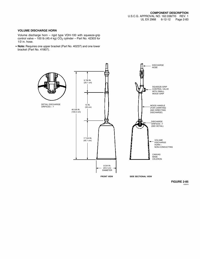
VOLUME DISCHARGE HORNVolume discharge horn – rigid type VDH-100 with squeeze-grip control valve – 100 lb (45.4 kg) CO2 cylinder – Part No. 42303 for 1/2 in. hose.Note: Requires one upper bracket (Part No. 40237) and one lower bracket (Part No. 41807).
FIGURE 2-85003616
COMPONENT DESCRIPTIONU.S.C.G. APPROVAL NO. 162.038/7/0 REV. 1
UL EX 2968 6-12-12 Page 2-83
SQUEEZE-GRIP CONTROL VALVE WITHSMALLWOODGRIP
DISCHARGE HOSE
WOODHANDLE(FOR CARRYINGAND DIRECTINGDISCHARGE)
8 3/4 IN.(22.2 cm)
DIAMETER
13 IN.(33 cm)
DISCHARGEORIFICES –7 (SEE DETAIL)
9 7/8 IN.(25.1 cm)
17 3/4 IN.(45.1 cm) VOLUME
DISCHARGEHORN – NON-CONDUCTING
CANVASBASECELERON
SIDE SECTIONAL VIEWFRONT VIEW
DETAIL DISCHARGEORIFICES – 7
40 5/8 IN.(103.2 cm)

COMPONENT DESCRIPTIONU.S.C.G. APPROVAL NO. 162.038/7/0UL EX 2968 1-19-09 Page 2-84
HOSE REEL INSTRUCTION PLATE – SIZE IV (PART NO. 41924)
FIGURE 2-86000724
5 5/16 IN.(13.5 cm)
7/32 IN. (5.6 mm) HOLE(4 REQUIRED)
1/4 IN.(6 mm)
4 3/8 IN.(11.1 cm)
7 1/2 IN.(19.1 cm)
7 IN.(17.8 cm)

COMPONENT DESCRIPTIONU.S.C.G. APPROVAL NO. 162.038/7/0UL EX 2968 1-19-09 Page 2-85
HOSE REEL INSTRUCTION PLATE – SIZE V (PART NO. 41923)
FIGURE 2-87008335
5 5/16 IN.(13.5 cm)
7/32 IN. (5.6 mm) HOLE(4 REQUIRED)
1/4 IN.(6 mm)
4 3/8 IN.(11.1 cm)
7 1/2 IN.(19.1 cm)
7 IN.(17.8 cm)
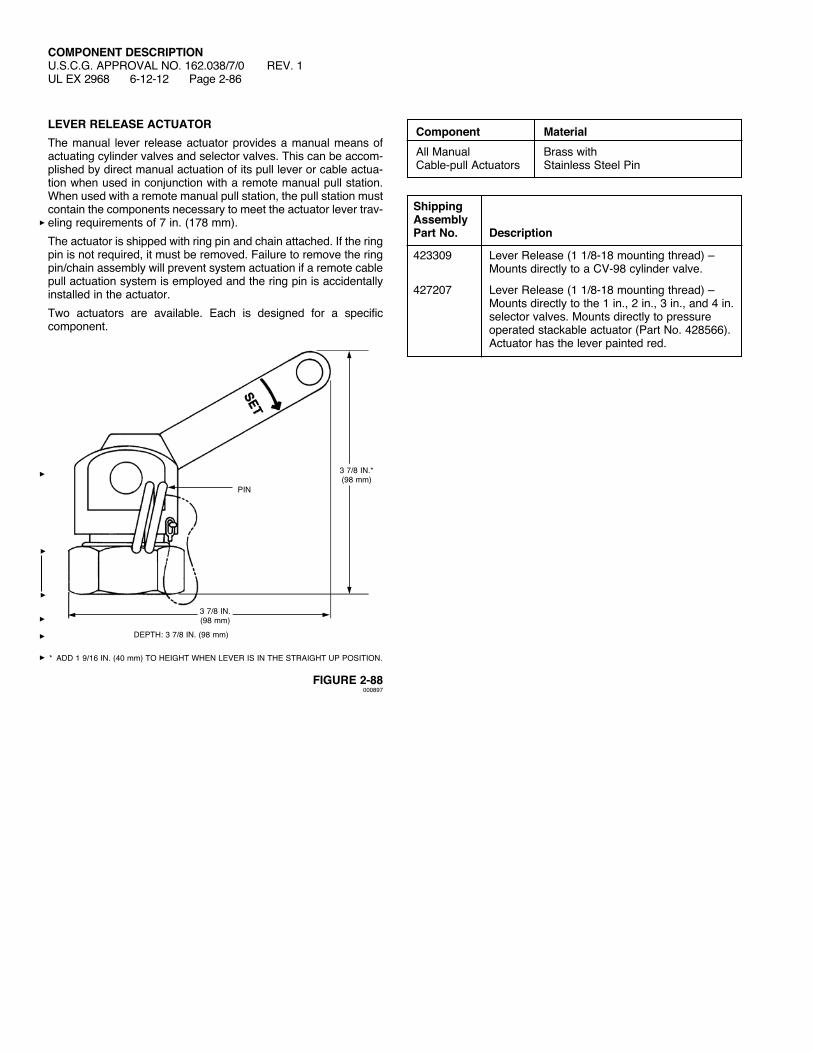
COMPONENT DESCRIPTIONU.S.C.G. APPROVAL NO. 162.038/7/0 REV. 1UL EX 2968 6-12-12 Page 2-86
LEVER RELEASE ACTUATORThe manual lever release actuator provides a manual means of actuating cylinder valves and selector valves. This can be accom-plished by direct manual actuation of its pull lever or cable actua-tion when used in conjunction with a remote manual pull station. Whenusedwitharemotemanualpullstation,thepullstationmustcontain the components necessary to meet the actuator lever trav-eling requirements of 7 in. (178 mm).The actuator is shipped with ring pin and chain attached. If the ring pin is not required, it must be removed. Failure to remove the ring pin/chain assembly will prevent system actuation if a remote cable pull actuation system is employed and the ring pin is accidentally installed in the actuator.Two actuators are available. Each is designed for a specific component.
FIGURE 2-88000897
Component MaterialAll Manual Brass withCable-pull Actuators Stainless Steel Pin
3 7/8 IN.(98 mm)
DEPTH: 3 7/8 IN. (98 mm)
3 7/8 IN.*(98 mm)
* ADD 1 9/16 IN. (40 mm)TOHEIGHTWHENLEVERISINTHESTRAIGHTUPPOSITION.
PIN
ShippingAssemblyPart No. Description
423309 Lever Release (1 1/8-18 mounting thread) – Mounts directly to a CV-98 cylinder valve.
427207 Lever Release (1 1/8-18 mounting thread) – Mounts directly to the 1 in., 2 in., 3 in., and 4 in. selector valves. Mounts directly to pressure operated stackable actuator (Part No. 428566). Actuator has the lever painted red.
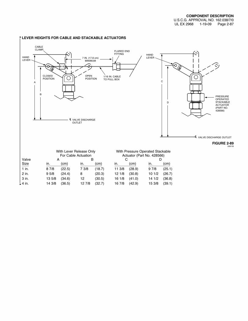
COMPONENT DESCRIPTIONU.S.C.G. APPROVAL NO. 162.038/7/0UL EX 2968 1-19-09 Page 2-87
LEVER HEIGHTS FOR CABLE AND STACKABLE ACTUATORS
FIGURE 2-89008139
WithLeverReleaseOnly WithPressureOperatedStackable For Cable Actuation Actuator (Part No. 428566)Valve A B C DSize in. (cm) in. (cm) in. (cm) in. (cm)1 in. 8 7/8 (22.5) 7 3/8 (18.7) 11 3/8 (28.9) 9 7/8 (25.1)2 in. 9 5/8 (24.4) 8 (20.3) 12 1/8 (30.8) 10 1/2 (26.7)3 in. 13 5/8 (34.6) 12 (30.5) 16 1/8 (41.0) 14 1/2 (36.8)4 in. 14 3/8 (36.5) 12 7/8 (32.7) 16 7/8 (42.9) 15 3/8 (39.1)
B
A
D
C
HAND LEVER
CABLE CLAMP
HAND LEVER
PRESSURE OPERATED STACKABLE ACTUATOR (PART NO. 428566)
CLOSED POSITION
OPEN POSITION
1/16 IN. CABLE TO PULL BOX
FLARED END FITTING
7 IN. (17.8 cm)MINIMUM
VALVE DISCHARGE OUTLET
VALVE DISCHARGE OUTLET
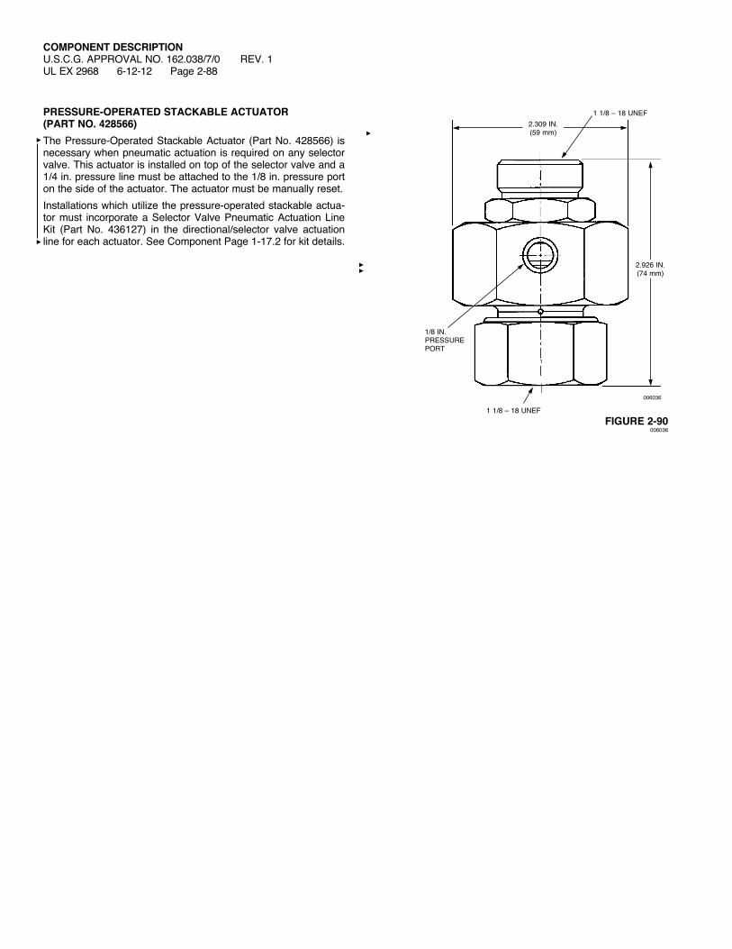
COMPONENT DESCRIPTIONU.S.C.G. APPROVAL NO. 162.038/7/0 REV. 1UL EX 2968 6-12-12 Page 2-88
PRESSURE-OPERATED STACKABLE ACTUATOR (PART NO. 428566)The Pressure-Operated Stackable Actuator (Part No. 428566) is necessary when pneumatic actuation is required on any selector valve. This actuator is installed on top of the selector valve and a 1/4 in. pressure line must be attached to the 1/8 in. pressure port on the side of the actuator. The actuator must be manually reset.Installations which utilize the pressure-operated stackable actua-tor must incorporate a Selector Valve Pneumatic Actuation Line Kit (Part No. 436127) in the directional/selector valve actuation line for each actuator. See Component Page 1-17.2 for kit details.
FIGURE 2-90006036
006036
2.309 IN.(59 mm)
1/8 IN.PRESSUREPORT
1 1/8 – 18 UNEF
1 1/8 – 18 UNEF
2.926 IN.(74 mm)

COMPONENT DESCRIPTIONU.S.C.G. APPROVAL NO. 162.038/7/0UL EX 2968 1-19-09 Page 2-89
SELECTOR VALVESSelector valves are used to control the flow of CO2 into the protected space(s).Every valve must have a lever actuator installed to it. Valves can be operated either pneumatically, manually, or by means of a remote cable pull station.When pneumatic actuation is required, a Stackable ActuatorAssembly, Part No. 428566, must be ordered separately.Selector valves can be manually operated by mounting Lever Actuator, Part No. 427207, directly onto the valve.Note: The Selector Valve Adaptor, Part No. 430832, can also be used to retrofit older model 1/2 in. through 2 1/2 in. selector valves, Part Nos. 57428-57433, when used in conjunction with Lever Release, Part No. 427207 and the Pressure Operated Stackable Actuator, Part No. 428566.
Component Material Thread Size/Type 1 in. Selector Valve Bronze 1 in. NPT Female (Used for 1/2 in., 3/4 in. and 1 in. pipe sizes) 2 in. Selector Valve Bronze 2 in. NPT Female (Used for 1 1/4 in., 1 1/2 in. and 2 in. pipe sizes) 3 in. Selector Valve Ductile 3 in. Flange Iron American Standard Raised Face 4 in. Selector Valve Ductile 4 in. Flange Iron American Standard Raised Face
ShippingAssemblyPart No. Description
427185 1 in. selector valve – threaded427150 2 in. selector valve – threaded57433 3 in. selector valve – flanged57445 4 in. selector valve – flanged
A B C Weight Valve Size Body in. (cm) in. (cm) in. (cm) lb. (kg)
1 in. Threaded – 5 1/2 (14.0) 2 9/16 (6.5) 7 (17.8) 14 (6.4) 1 in. NPT female
2 in. Threaded – 7 1/2 (19.1) 3 1/2 (8.9) 8 9/16 (21.7) 32 (14.5) 2 in. NPT female
3 in. Flanged – 3 in. 13 (33.0) 6 1/8 (15.6) 15 (38.1) 115 (52.2)
4 in. Flanged – 4 in. 16 (40.6) 8 1/4 (21.0) 18 (45.7) 230 (104.3)
3 IN. AND 4 IN. FLANGED VALVE
006035
1 IN. AND 2 IN. THREADED VALVE
A
D
1 1/8 – 18 UNEF
C
A
008140
NOTE: FOR 2 IN. and 2 1/2 IN. FLANGE SELECTOR VALVES, USE A 3 IN. FLANGE VALVE. FIGURE 2-91
SELECTOR VALVE ADAPTOR, PART NO. 430832
1 1/8 – 18 UNEF
600 LB AMERICAN STANDARD RAISED FACE FLANGE (INLET AND OUTLET) (MATING FLANGES SUPPLIED BY OTHERS)
B
C

COMPONENT DESCRIPTIONU.S.C.G. APPROVAL NO. 162.038/7/0 REV. 1UL EX 2968 7-14-14 Page 2-90
ODORIZERThe odorizer is used to inject a small amount of wintergreen scent into the carbon dioxide while flowing through the piping network. Whenthecarbondioxidedischarges into thehazardarea, itwillcarry a scent of wintergreen with it. This wintergreen scent is a warning to personnel entering the hazard area that the area contains a concentration of carbon dioxide and precautions must be taken, either leave the area immediately or secure proper breathing apparatus. The internal ampoule containing the oil of wintergreen in the odorizer must be replaced after each system discharge.
FIGURE 2-92000698
9 1/2 IN.(24.1 cm)
Shipping Assembly Part No. Description42278 Odorizer 42284 Replacement ampoule 42280 Nameplate
Component Material Thread Size/Type
Odorizer Steel 3/4 in. NPT Male