marine cable catalogue - prysmian group...lloyds register (lr) lr is a leading international...
TRANSCRIPT

Marine Cable Catalogue
NORTH EUROPE

As the worldwide leader in the cable industry, Prysmian Group believes in the effective, efficient and sustainable supply of energy and information as a primary driver in the development of communities.
With this in mind, we provide major global organisations in many industries with best-in-class cable solutions, based on state-of-the-art technology.
Through two renowned commercial brands - Prysmian and Draka - based in almost 50 coun-tries, we‘re constantly close to our customers, enabling them to further develop the world‘s energy and telecoms infrastructures and achieve sustainable and profitable growth.
Linking the futureFor our energy business, we design, produce, distribute and install cables and systems for the transmission and distribution of power at low, medium, high and extra-high voltage.
For telecoms, the Group is a leading manufacturer of all types of copper and fibre cables, systems and accessories for voice, video and data trans-mission.
Drawing on over 130 years‘ experience and continuously investing in R&D, we apply excellence, understanding and integrity to everything we do, meeting and exceeding the needs of our customers across all continents - while at the same time shaping the evolution of our industry.
2
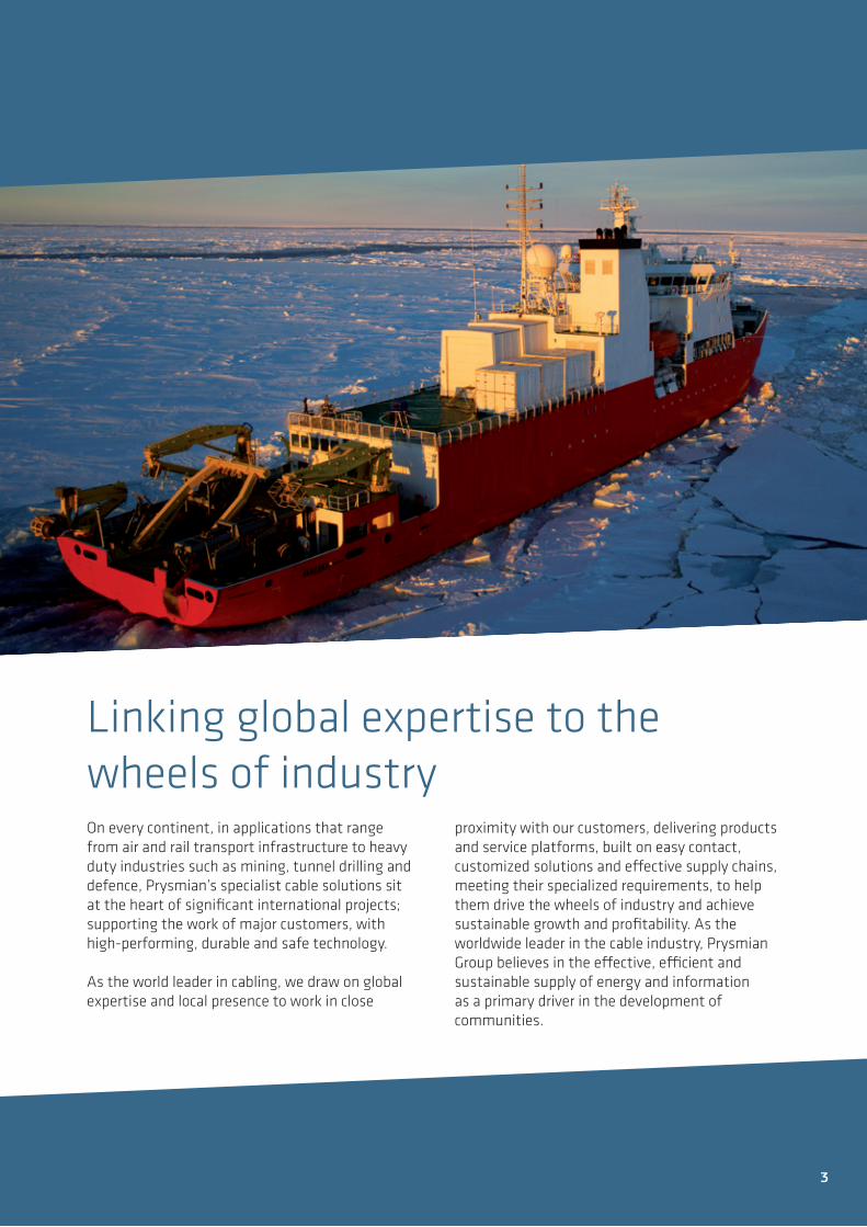
Linking global expertise to the wheels of industryOn every continent, in applications that range from air and rail transport infrastructure to heavy duty industries such as mining, tunnel drilling and defence, Prysmian’s specialist cable solutions sit at the heart of significant international projects; supporting the work of major customers, with high-performing, durable and safe technology.
As the world leader in cabling, we draw on global expertise and local presence to work in close
proximity with our customers, delivering products and service platforms, built on easy contact, customized solutions and effective supply chains, meeting their specialized requirements, to help them drive the wheels of industry and achieve sustainable growth and profitability. As the worldwide leader in the cable industry, Prysmian Group believes in the effective, efficient and sustainable supply of energy and information as a primary driver in the development of communities.
3

Marine CablesMarine cables (ship wiring and ship board cables) are for installation on board ships. They have been type approved by a classification society and they have a construction that adheres to standards for marine cables, such as: They are based on an amount of 7 litres of combustible material per metre. Bunched cables have to be minimum 3.5 meters tall, when they are in a test chamber subjected to fire from a burner directed at the cables for 40 minutes. The bunched cables may not burn more than 2.5 meters above the burner.See figure 2. on page 6. ConductorMarine cable conductors are made with stranded annealed copper, combining flexibility and small dimensions to provide excellent handling. To minimise the cable diameter and weight sector shaped conductors are used for bigger cross-section.
Fire Resistance These tests are aimed at verifying the behaviour of a cable´s circuit integrity during fire. The main three test methods are IEC 60331-21, IEC 60331-1 and IEC 60331-2, the latter is used for power and control cables. Marine cable standards require a IEC 60331-21 test, where the cable is exposed to a flame at 750˚C for 90 minutes followed by a 15 minutes cooling period, while the rated voltage is being applied. No breakdown or short circuit is permitted during the test. See figure 3. on page 6.
The optional test methods for cables with diameters over 20 mm, is the more rigorous IEC 60331-1 test. For cable diameter not exceeding 20 mm test IEC 60331-2 can also be used, in which a bent cable, affected by mechanical shock, is subjected to a 830˚C flame for minimum 90 minutes.
Insulation MaterialXLPE is used as the main insulation material. It withstands higher temperatures than ordinary thermoplastic polyethylene. It is resistant against deformation and various chemicals, with excellent mechanical and electrical properties. The maximum conductor temperature stipulated by IEC 60092-360 marine cable standard is 90˚C.
Sheathing MaterialThe sheath is composed of halogen free, flame retardant thermoplastic compound. It fulfils the criterion of SHF1 according to IEC 60092-360. In case of fire the sheathing material offers advantages such as reduced emission of smoke and corrosive toxic gasses.
Smoke DensitySmoke density is tested according to IEC 61034-1 (apparatus) and IEC 61034-2 (procedure and requirements). It is done by placing a cable in a ”smoke cube” (3x3x3 m). When the cable is burning, the light transmittance is measured using a photometric system. 60 % (70 % for a single cable) visibility is satisfactory if it is attained throughout the test.
HalogensTo test whether a material is halogen free or not, test IEC 60754-1 and 60754-2 are used. The acidity of the gasses from burning materials is measured. Halogen-free means that the materials used in the cable do not contain any halogens – such as chlorine, bromine, iodine or fluorine. In order to attain a self-extinguishing effect that halogens have in cables, ATH (aluminium trihydroxide) based materials are used instead. This way the negative effects of halogens are avoided.
4

General information
5

Fire Testing MethodsFlame retardance of a single cable is tested in accordance with IEC 60332-1-2. It is performed on a 60 cm cable sample with a gas flame for 1-8 minutes depending on the cable diameter. The cable has to be self-extinguishing up to a certain limit to fulfil the test. Flame spread is tested on bunched cables in accordance with IEC 60332-3-22, which simulating the fire behaviour of cables installed in a bunch. The main category used is type A.
Test MethodsIEC 60331-1 & 2 for fire with shock at a temperature of at least 830°C. Bunched cables are tested for flame spread.
Quality ControlEach manufactured cable goes through a test procedure according to the IEC 60092-300 series standards.
6
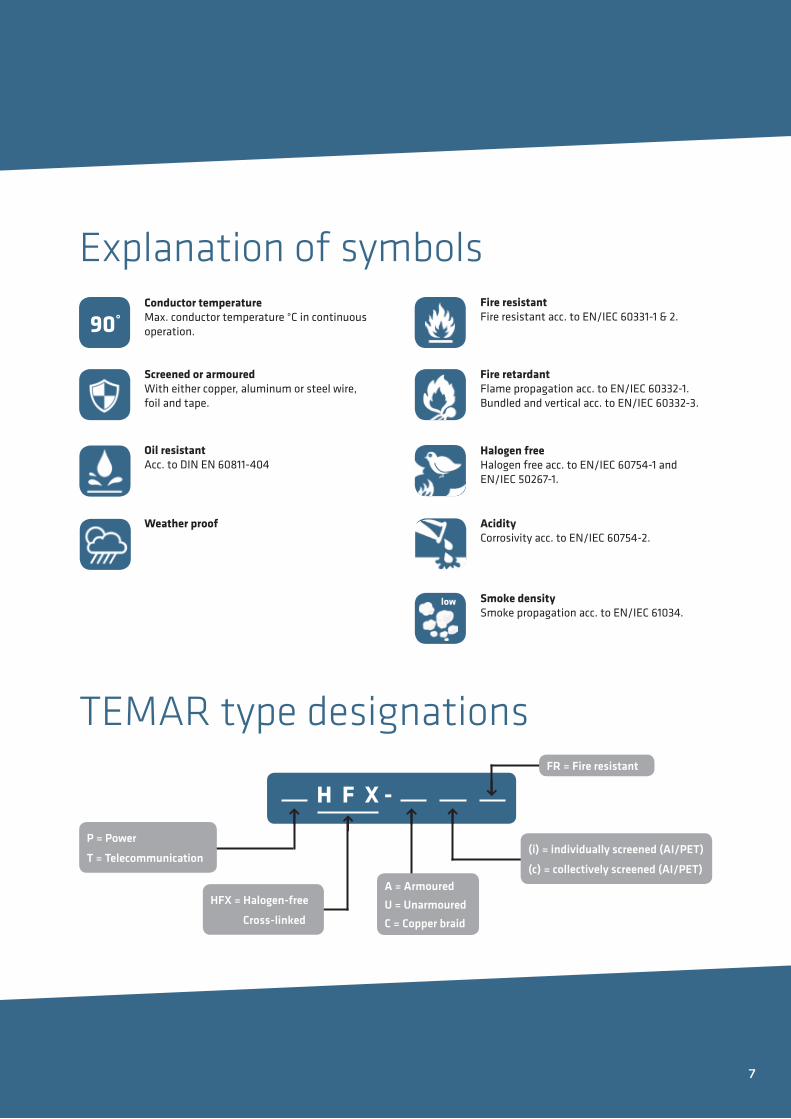
Explanation of symbols
90°
low
Acidity Corrosivity acc. to EN/IEC 60754-2.
Fire resistantFire resistant acc. to EN/IEC 60331-1 & 2.
Weather proof
Screened or armouredWith either copper, aluminum or steel wire, foil and tape.
Fire retardantFlame propagation acc. to EN/IEC 60332-1.Bundled and vertical acc. to EN/IEC 60332-3.
Halogen freeHalogen free acc. to EN/IEC 60754-1 andEN/IEC 50267-1.
Smoke densitySmoke propagation acc. to EN/IEC 61034.
Conductor temperatureMax. conductor temperature °C in continuousoperation.
Oil resistantAcc. to DIN EN 60811-404
TEMAR type designations
H F X - P = Power
T = Telecommunication
HFX = Halogen-free
Cross-linked
(i) = individually screened (AI/PET)
(c) = collectively screened (AI/PET)
FR = Fire resistant
↑ ↑↑ ↑
↑
A = ArmouredU = Unarmoured C = Copper braid
7

Bureau Veritas (BV) Created in 1828, Bureau Veritas is a global leader in Testing, Inspection and Certification (TIC), delivering high quality services to help manufac-tors meet the growing challenges of quality, safety, environmental protection and social responsibility. Bureau Veritas is an accredited EU recognised organisation allowed to provide EU Mutual Recognition Type Approval services according to certification, described in rule notes NR 320 and NR 266.
Marine Approvals
Russian Maritime Register of Shipping(RMRS)The classification society Russian Maritime Register of Shipping (RS) was established in 1913 and has been a member of IACS since 1969. Today RS is recognized by the European Union and in compliance with EC Regulation 391/2009. As well as certified by QACE. RMRS offers technical design assessment, surveys and issuing of documents, certificates and reports to ships and offshore installations as well as for ship logistics, machinery, equipment, products and materials.
As a manufacturer we must be able to prove to our customers in the maritime industry, that our cables comply with rules and regulations pertaining to the particular type of cable and its application purpose on vessels.
Prysmian Group uses a variety of recogniced and accredited third-party organisations to test and certifify our cables - to ensure the highest lavel of safety and quality for our customers.
Den Norske Veritas and Germanischer Lloyds (DNV-GL) Norske Veritas (DNV) founded in Olso, Norway in 1864 and Germanischer Lloyd (GL) established in Hamburg Germany in 1867 was merged in 2013 and today it is a globally leading quality assurance and risk management company. DNV- GL offer technical services such as design assessment, type approvals, third-party inspection, verification and testing. Includingcertification of materials, components and systems relevant to the safe operation and quality of ships and offshore installations.
8

Lloyds Register (LR)LR is a leading international provider of classification, compliance and consultancy services to the marine and offshore industries, helping our clients design, construct and operate their assets to the highest levels of safety and performance.
Manufacturers whose products will be used on board a vessel classed with Lloyd's Register must get their products certified to meet the LR Marine & Offshore Rules.
Classification with Lloyd’s Register means adding value to our products. This helps merchants manage their ships and offshore assets to their full potential, maintain operational effectiveness and minimise risk to life, property and the environment.
The Royal Institue of Naval Architects(RINA)The Royal Institution of Naval Architects (RINA), is an internationally renowned professional institution whose members are involved at all levels in the design, construction, maintenance and operation of marine vessels and structures. Certification is compulsory for products covering essential services to be fitted on board RINA-classed ships, and it is carried out in accordance with their rules for testing, certification and acceptance of marine materials and equipment.
American Bureau of Shipping (ABS)The American Bureau of Shipping (ABS) is a classification society, with a mission to promote the security of life, property and the natural environment, primarily through the development and verification of standards for the design, construction and operational maintenance of marine-related facilities.
9

10

POWER & CONTROL CABLES UP TO 3 KV
Unarmoured 0,6/1 (1,2) kV
TEMAR PHFX-U (LM-HF) . . . . . . . . . . . . . . . . . . . . . . . . . . .12
Armoured 0,6/1 kV
TEMAR PHFX-A (LSM-HF) . . . . . . . . . . . . . . . . . . . . . . . . . . 16
Armoured 1,8/3 (3,6) kV
TEMAR PHFX-A (LSM-HF) . . . . . . . . . . . . . . . . . . . . . . . . . .20
INSTRUMENTATION & COMMUNICATION CABLES UP TO 300 V
Screened 150/250 (300) V
TEMAR THFX-U(c) (LJT-HF) . . . . . . . . . . . . . . . . . . . . . . . .22
Armoured 150/250 (300) V
TEMAR THFX-C (LJST-HF) . . . . . . . . . . . . . . . . . . . . . . . . . . 24
Individually screened 250 V
HFX-ISOSA/CU . . . . . . . . . . . . . . . . . . . . . . . . . . . . . . . . . . .26
Bus cable 100 V
SIENOPYR-FR PROFIBUS M-02Y(ST)CHX . . . . . . . . . . . .28
FIRE RESISTANT CABLES UP TO 1 kV
Unarmoured Power & Control 0,6/1 (1,2) KV
TEMAR PHFX-UFR (LM-FRHF) . . . . . . . . . . . . . . . . . . . . . .30
Armoured Power & Control 0,6/1 (1,2) kV
TEMAR PHFX-AFR (LSM-FRHF) . . . . . . . . . . . . . . . . . . . . .32
Armoured 150/250 (300) V Instrumentation, Communication & Control
SIENOPYR-FR FMHXCH FE 120 . . . . . . . . . . . . . . . . . . . .34
MEDIUM VOLTAGE CABLES UP TO 24 KV
Armoured 6/10 (12) kV
MV-FHFX/A . . . . . . . . . . . . . . . . . . . . . . . . . . . . . . . . . . . . . .36
Armoured 12/20 (24) kV
MV-FHFX/A . . . . . . . . . . . . . . . . . . . . . . . . . . . . . . . . . . . . . .38
TECHNICAL DATA
General information . . . . . . . . . . . . . . . . . . . . . . . . . . . . . . .40
Laying . . . . . . . . . . . . . . . . . . . . . . . . . . . . . . . . . . . . . . . . . . 41
Rated current . . . . . . . . . . . . . . . . . . . . . . . . . . . . . . . . . . . . .42
Identification colors . . . . . . . . . . . . . . . . . . . . . . . . . . . . . . .43
Electrical data . . . . . . . . . . . . . . . . . . . . . . . . . . . . . . . . . . . .44
P R O D U C T S
11
6
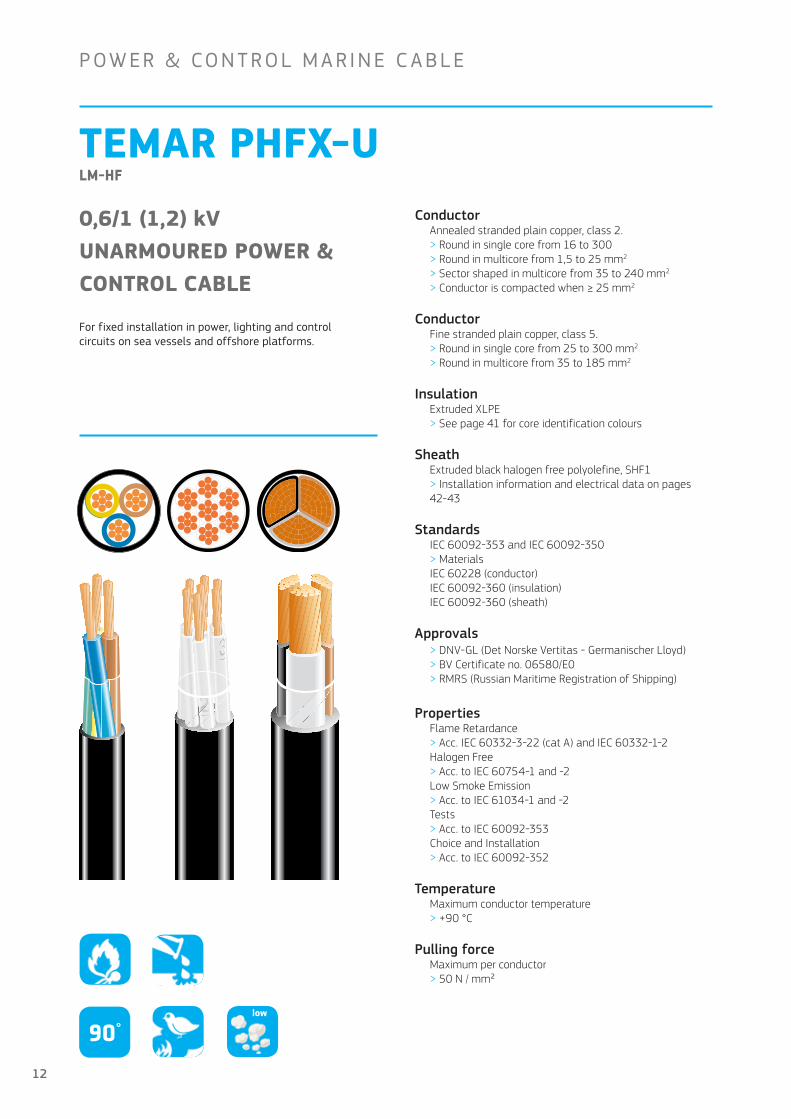
TEMAR PHFX-U LM-HF
ConductorAnnealed stranded plain copper, class 2 . > Round in single core from 16 to 300> Round in multicore from 1,5 to 25 mm2
> Sector shaped in multicore from 35 to 240 mm2
> Conductor is compacted when ≥ 25 mm2
ConductorFine stranded plain copper, class 5 .> Round in single core from 25 to 300 mm2
> Round in multicore from 35 to 185 mm2
InsulationExtruded XLPE> See page 41 for core identification colours
SheathExtruded black halogen free polyolefine, SHF1> Installation information and electrical data on pages 42-43
StandardsIEC 60092-353 and IEC 60092-350> MaterialsIEC 60228 (conductor)IEC 60092-360 (insulation)IEC 60092-360 (sheath)
Approvals> DNV-GL (Det Norske Vertitas - Germanischer Lloyd)> BV Certificate no . 06580/E0> RMRS (Russian Maritime Registration of Shipping)
PropertiesFlame Retardance > Acc . IEC 60332-3-22 (cat A) and IEC 60332-1-2Halogen Free > Acc . to IEC 60754-1 and -2Low Smoke Emission> Acc . to IEC 61034-1 and -2Tests> Acc . to IEC 60092-353Choice and Installation> Acc . to IEC 60092-352
TemperatureMaximum conductor temperature > +90 °C
Pulling forceMaximum per conductor > 50 N / mm²
0,6/1 (1,2) kVUNARMOURED POWER & CONTROL CABLE
For fixed installation in power, lighting and control circuits on sea vessels and offshore platforms.
P OW ER & CON T ROL M A R INE C A B L E
90°low
12

Conductor Cross-section mm
Including earth wire
Conductor height mm
Conductor width mm
Cable diameter mm
Cable weight kg /km
Bending radius fixed mm
POWER CABLES1 x 16 5,0 – 9,0 200 75
1 x 25 5,8 – 10,5 300 85
1 x 35 6,9 – 11,5 405 95
1 x 50 7,9 – 13,0 530 110
1 x 70 9,6 – 15,5 745 130
1 x 95 11,3 – 17,0 1000 140
1 x 120 12,7 – 19,0 1260 155
1 x 150 14,1 – 21,0 1550 170
1 x 185 15,7 – 23,5 1910 190
1 x 240 18,1 – 26,0 2490 210
1 x 300 20,2 – 29,0 3090 235
2 x 1,5 1,6 – 8,5 90 35
2 x 2,5 2,0 – 9,5 120 40
2 x 4 2,6 – 10,5 165 45
2 x 6 3,1 – 12,0 210 50
3 x 1,5 3G1,5 1,6 – 9,0 105 40
3 x 2,5 3G2,5 2,0 – 10,0 145 40
3 x 4 3G4 2,6 – 11,5 205 50
3 x 6 3G6 3,1 – 12,5 260 50
3 x 10 4,0 – 15,0 430 60
3 x 16 5,0 – 17,5 635 70
3 x 25 5,8 – 20,5 955 85
3 x 35 5,6 9,2 21,0 1220 170
3 x 50 6,5 10,7 24,0 1610 195
3 x 70 7,9 12,8 28,0 2230 230
3 x 95 9,3 15,1 32,0 3035 260
3 x 120 10,5 17,0 35,0 3790 280
3 x 150 11,6 18,9 39,0 4670 320
3 x 185 13,1 21,1 43,5 5810 350
3 x 240 15,0 24,4 49,0 7580 395
3 x 300 16,8 27,2 53,5 9410 430
4 x 1,5 4G1,5 1,6 – 9,8 130 40
4 x 2,5 4G2,5 2,0 – 11,0 180 45
4 x 4 4G4 2,6 – 12,5 260 50
4 x 6 4G6 3,1 – 14,0 350 60
4 x 10 4G10 4,0 – 16,5 545 70
4 x 16 4G16 5,0 – 19,5 820 80
4 x 25 4G25 5,8 – 23,0 1240 95
4 x 35 4G35 6,2 8,6 23,5 1610 190
4 x 50 4G50 7,2 9,9 27,5 2120 220
4 x 70 4G70 8,6 12,0 32,0 2960 260
4 x 95 4G95 10,2 14,1 36,0 4000 290
4 x 120 4G120 11,5 15,8 40,0 5010 320
– 5G1,5 1,6 – 11,0 165 45
– 5G2,5 2,0 – 12,0 220 50
– 5G6 3,1 – 15,5 440 65
– 5G10 4,0 – 18,0 660 75
– 5G16 5,0 – 21,0 1000 85
– 5G25 5,8 – 25,5 1530 155
13

Conductor Cross-section mm
Earth wire version
Conductor height mm
Conductor width mm
Cable diameter mm
Cable weight kg /km
Bending radius fixed mm
CONTROL CABLES7 x 1,5 1,6 – 12,0 200 50
12 x 1,5 1,6 – 16,0 330 65
19 x 1,5 1,6 – 18,5 490 75
27 x 1,5 1,6 – 22,5 680 90
7 x 2,5 2,0 – 13,5 280 55
12 x 2,5 2,0 – 18,0 460 75
19 x 2,5 2,0 – 21,0 690 85
CLASS 5 CONDUCTOR (F)
1 x 25 6,5 – 11,5 295 50
1 x 35 7,6 – 12,5 390 75
1 x 50 9,2 – 14,5 550 90
1 x 70 11,0 – 17,0 770 105
1 x 95 13,5 – 19,5 990 120
1 x 120 14,9 – 21,5 1250 130
1 x 150 17,2 – 24,5 1560 150
1 x 185 17,9 – 25,5 1850 160
1 x 240 20,6 – 29,0 2440 180
1 x 300 24,0 – 33,0 3070 200
3 x 35 7,6 – 27,0 1570 170
3 x 50 9,2 – 31,5 2150 190
3 x 70 11,0 – 37,0 3040 230
3 x 95 13,5 – 42,5 3930 260
3 x 120 14,9 – 46,5 4900 280
3 x 150 17,2 – 53,5 6190 330
3 x 185 17,9 – 56,0 7290 340
4 x 35 7,6 – 30,5 1960 190
4 x 50 9,14 – 33,0 2430 200
4 x 70 11,0 – 41,0 3820 250
4 x 95 13,5 – 48,0 5000 290
4 x 120 14,9 – 52,5 6260 320
4 x 150 17,2 – 59,5 7840 360
4 x 185 17,9 – 63,0 9240 380
– 5G35 7,6 – 32,5 2420 200
– 5G50 9,2 – 39,5 3360 240
– 5G70 11,0 – 45,5 4690 280
– 5G95 13,5 – 53,0 6140 320
14

15
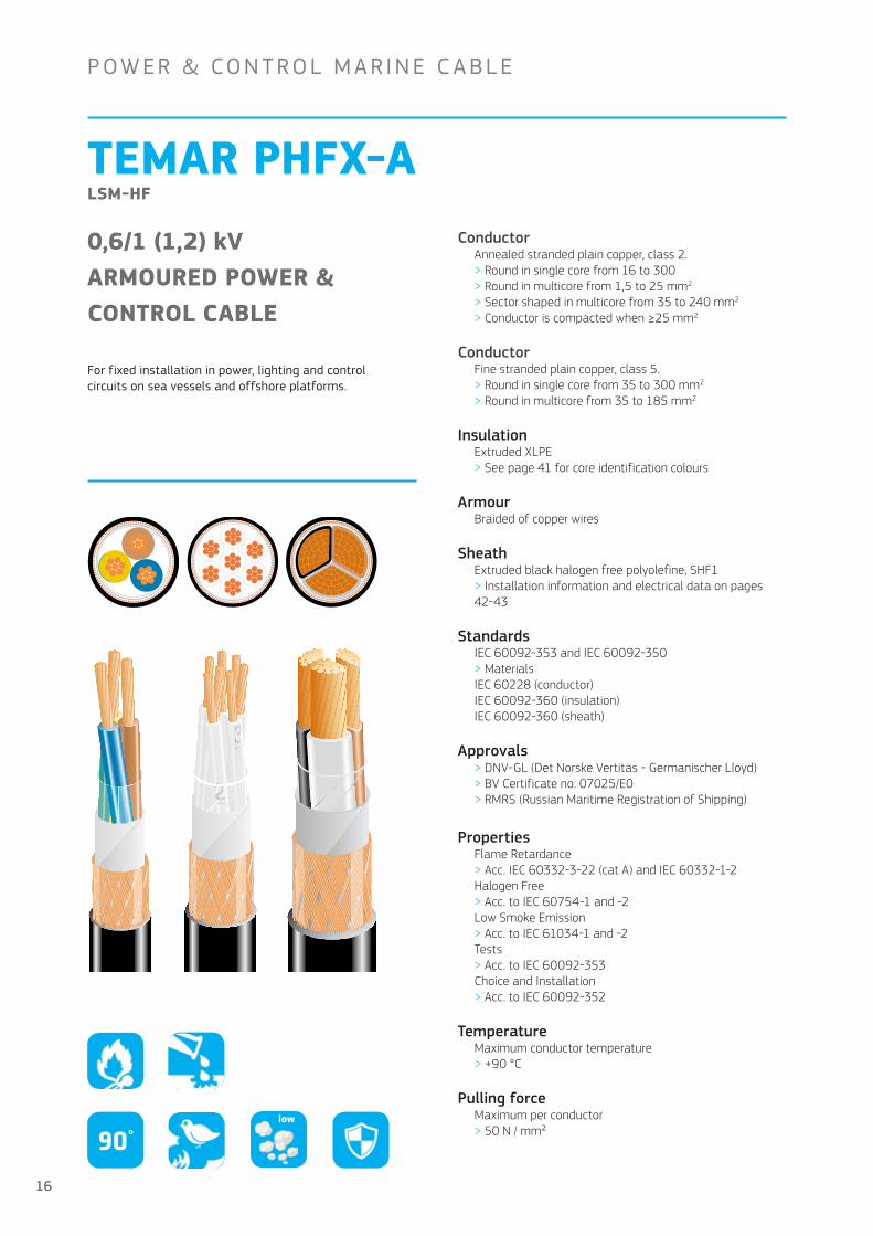
TEMAR PHFX-ALSM-HF
0,6/1 (1,2) kVARMOURED POWER &CONTROL CABLE
For fixed installation in power, lighting and control circuits on sea vessels and offshore platforms.
ConductorAnnealed stranded plain copper, class 2 .> Round in single core from 16 to 300> Round in multicore from 1,5 to 25 mm2
> Sector shaped in multicore from 35 to 240 mm2
> Conductor is compacted when ≥25 mm2
ConductorFine stranded plain copper, class 5 .> Round in single core from 35 to 300 mm2
> Round in multicore from 35 to 185 mm2
InsulationExtruded XLPE> See page 41 for core identification colours
ArmourBraided of copper wires
SheathExtruded black halogen free polyolefine, SHF1> Installation information and electrical data on pages 42-43
StandardsIEC 60092-353 and IEC 60092-350> MaterialsIEC 60228 (conductor)IEC 60092-360 (insulation)IEC 60092-360 (sheath)
Approvals> DNV-GL (Det Norske Vertitas - Germanischer Lloyd)> BV Certificate no . 07025/E0> RMRS (Russian Maritime Registration of Shipping)
PropertiesFlame Retardance > Acc . IEC 60332-3-22 (cat A) and IEC 60332-1-2Halogen Free > Acc . to IEC 60754-1 and -2Low Smoke Emission> Acc . to IEC 61034-1 and -2Tests> Acc . to IEC 60092-353Choice and Installation> Acc . to IEC 60092-352
TemperatureMaximum conductor temperature > +90 °C
Pulling forceMaximum per conductor > 50 N / mm²
P OW ER & CON T ROL M A R INE C A B L E
90°low
16

Conductor cross-section mm
Earth wire version
Conductor height mm
Conductor width mm
Diameter over braid mm
Cable diameter mm
Cable weight kg /km
Bending radius, fixed mm
POWER CABLES
1 x 16 5,1 – 7,7 10,5 255 65
1 x 25 5,8 – 9,0 11,5 360 70
1 x 35 6,9 – 10,5 13,0 475 80
1 x 50 7,9 – 11,5 14,5 595 90
1 x 70 9,6 – 14,0 17,0 860 105
1 x 95 11,3 – 16,0 19,0 1135 120
1 x 120 12,7 – 17,5 21,0 1400 130
1 x 150 14,1 – 19,5 23,0 1700 140
1 x 185 15,7 – 21,5 25,0 2095 150
1 x 240 18,1 – 24,0 28,0 2650 170
1 x 300 20,2 – 26,5 30,5 3320 185
2 x 1,5 1,6 – 7,5 10,0 130 60
2 x 2,5 2,0 – 8,5 11,0 160 70
2 x 4 2,6 – 9,5 11,5 200 70
2 x6 3,1 10,5 13,0 255 80
3 x 1,5 3G1,5 1,6 – 8,0 10,0 150 60
3 x 2,5 3G2,5 2,0 – 9,0 11,5 195 70
3 x 4 2,6 – 10,0 13,0 270 80
3 x 6 3,1 – 11,0 14,0 320 85
3 x 10 4,0 – 13,5 16,5 520 100
3 x 16 5,0 – 16,0 19,0 740 115
3 x 25 5,8 – 18,5 22,0 1050 135
3 x 35 5,6 9,2 19,0 23,0 1350 185
3 x 50 6,5 10,7 21,5 25,5 1750 205
3 x 70 7,9 12,8 25,0 29,0 2400 235
3 x 95 9,3 15,1 28,0 33,0 3200 265
3 x 120 10,5 17,0 31,5 36,5 4100 295
3 x 150 11,6 18,9 35,0 41,0 5000 330
3 x 185 13,1 21,1 39,5 45,5 6350 365
4 x 1,5 4G1,5 1,6 – 8,5 11,0 180 70
4 x2,5 4G2,5 2,0 – 10,0 12,5 250 75
4 x 4 4G4 2,6 – 11,5 14,0 320 85
4 x 6 4G6 3,1 – 13,0 16,0 450 100
4 x 10 4G10 4,0 – 15,5 18,5 670 115
4 x 16 4G16 5,0 – 17,5 21,0 940 130
4 x 25 4G25 5,8 – 20,5 24,0 1350 145
4 x 35 4G35 6,2 8,6 21,5 25,5 1750 205
4 x 50 4G50 7,2 9,9 24,5 29,0 2300 235
4 x 70 4G70 8,6 12,0 28,0 33,0 3200 265
4 x 95 4G95 10,2 14,1 32,0 37,0 4300 300
4 x 120 4G120 11,5 15,8 36,0 41,0 5300 330
5 x 1,5 5G1,5 1,6 – 9,5 12,0 220 75
5 x 2,5 5G2,5 2,0 – 11,0 13,5 290 85
17

Conductor cross-section mm
Earth wire version
Conductor height mm
Conductor width mm
Diameter over braid mm
Cable diameter mm
Cable weight kg /km
Bending radius, fixed mm
CONTROL CABLES
7 x 1,5 1,6 – 10,5 13,0 270 80
12 x 1,5 1,6 – 14,5 17,0 460 105
19 x 1,5 1,6 – 17,0 20,0 640 120
27 x 1,5 1,6 – 21,0 24,5 870 150
7 x 2,5 2,0 – 12,0 14,5 330 90
12 x 2,5 2,0 – 16,5 20,0 620 120
19 x 2,5 2,0 – 19,5 23,0 900 140
CLASS 5 CONDUCTOR (F)
1 x 35 7,6 11,0 14,0 470 85
1 x 50 9,9 – 15,0 17,5 700 105
1 x 70 11,0 – 17,0 19,0 920 115
1 x 95 13,5 – 19,0 21,0 1170 125
1 x 120 15,2 – 21,0 23,5 1450 140
1 x 150 17,2 – 24,0 26,0 1550 155
1 x 185 18,9 – 26,0 28,5 1770 170
1 x 240 21,8 – 30,0 32,0 2700 190
3 x 35 7,6 – 25,0 29,0 1800 180
3 x 50 9,2 – 29,0 33,0 2400 200
3 x 70 11,0 – 34,0 38,5 3360 235
3 x 95 13,5 – 40,0 45,0 4390 270
3 x 120 14,9 – 43,5 48,5 5390 295
3 x 150 17,2 – 50,0 55,5 6760 335
3 x 185 17,9 – 52,5 58,0 7860 350
4 x 35 7,6 – 27,5 31,5 2190 190
4 x 50 9,2 – 32,0 36,0 2970 220
4 x 70 11,0 – 38,5 43,0 4280 260
4 x 95 13,5 – 44,5 50,0 5510 300
4 x 120 14,9 – 49,0 54,5 6850 330
4 x 150 17,2 – 55,5 61,5 8488 370
4 x 185 17,9 – 58,5 65,0 10040 390
– 5G35 7,6 – 30,5 34,5 2690 210
– 5G50 9,2 – 35,5 40,0 3660 240
– 5G70 11,0 – 42,5 47,5 5210 285
– 5G95 14,5 – 50,0 55,0 6730 330
18
19
TEMAR PHFX-ALSM-HF
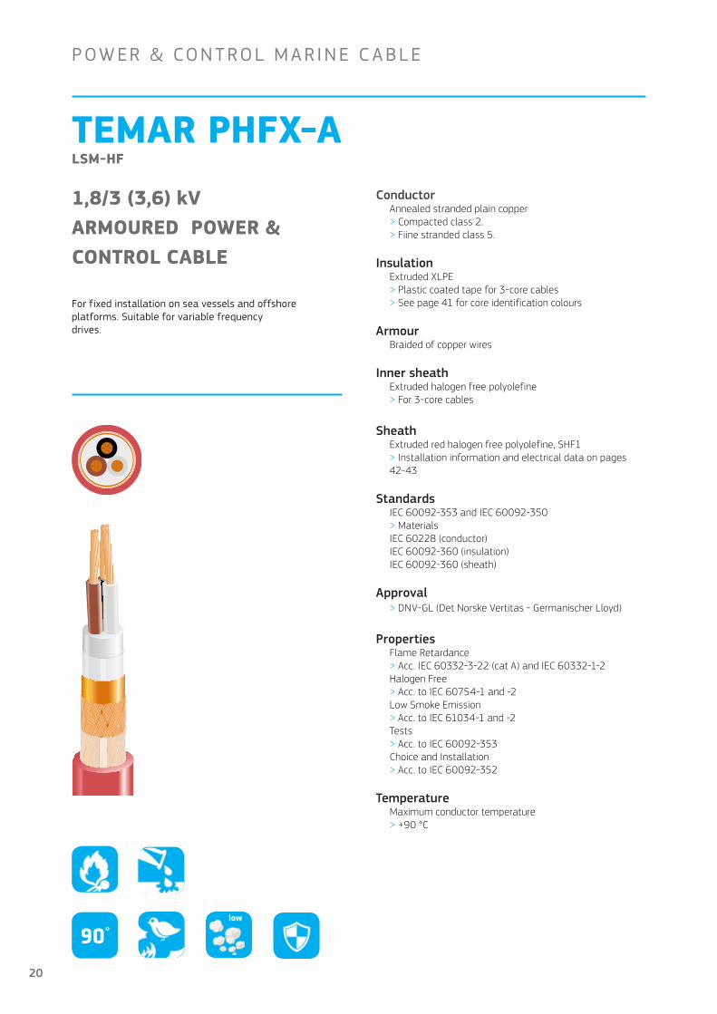
1,8/3 (3,6) kVARMOURED POWER &CONTROL CABLE
For fixed installation on sea vessels and offshore platforms. Suitable for variable frequency drives.
ConductorAnnealed stranded plain copper> Compacted class 2 .> Fiine stranded class 5 .
InsulationExtruded XLPE> Plastic coated tape for 3-core cables> See page 41 for core identification colours
ArmourBraided of copper wires
Inner sheathExtruded halogen free polyolefine> For 3-core cables
SheathExtruded red halogen free polyolefine, SHF1> Installation information and electrical data on pages 42-43
StandardsIEC 60092-353 and IEC 60092-350> MaterialsIEC 60228 (conductor)IEC 60092-360 (insulation)IEC 60092-360 (sheath)
Approval> DNV-GL (Det Norske Vertitas - Germanischer Lloyd)
PropertiesFlame Retardance > Acc . IEC 60332-3-22 (cat A) and IEC 60332-1-2Halogen Free > Acc . to IEC 60754-1 and -2Low Smoke Emission> Acc . to IEC 61034-1 and -2Tests> Acc . to IEC 60092-353Choice and Installation> Acc . to IEC 60092-352
TemperatureMaximum conductor temperature > +90 °C
P OW ER & CON T ROL M A R INE C A B L E
90°low
20

Conductor cross-section mm
Conductor diameter mm
Diameter over braid mm
Cable diameter mm
Cable weight kg /km
Bending radius, fixed mm
TEMAR PHFX-A 3 kV EMC
3 x 50/235 7,9 33 37 2900 340
3 x 70/35 9,6 37 42 3840 380
3 x 95/35 11,3 40 46 4880 420
3 x 120/40 12,7 44 50 5920 450
3 x 150/40 14,1 47 53 7000 480
TEMAR PHFX-A F 3 kV ECM (CLASS 5.)
3 x 95/35 13,5 46 51 5100 460
3 x 120/40 15,0 49 55 6170 500
21
TEMAR THFX-U(c) LJT-HF
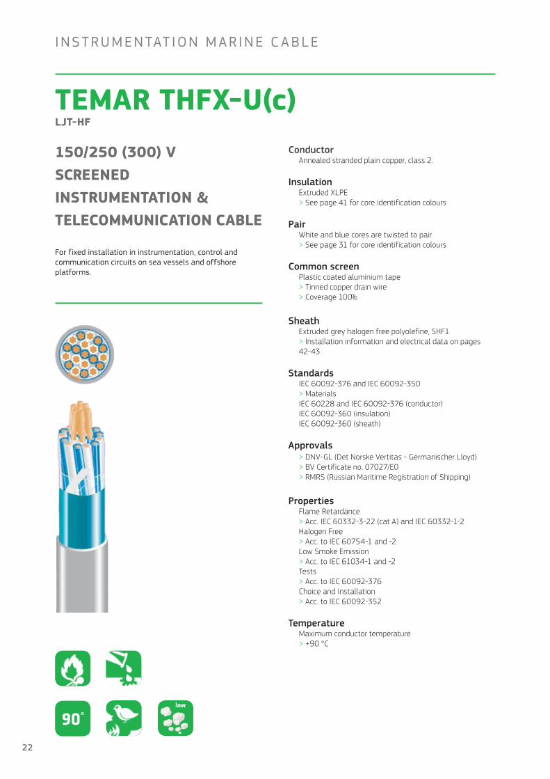
150/250 (300) V SCREENED INSTRUMENTATION &TELECOMMUNICATION CABLE
For fixed installation in instrumentation, control and communication circuits on sea vessels and offshore platforms.
ConductorAnnealed stranded plain copper, class 2 .
InsulationExtruded XLPE> See page 41 for core identification colours
PairWhite and blue cores are twisted to pair > See page 31 for core identification colours
Common screenPlastic coated aluminium tape> Tinned copper drain wire> Coverage 100 %
SheathExtruded grey halogen free polyolefine, SHF1> Installation information and electrical data on pages 42-43
StandardsIEC 60092-376 and IEC 60092-350> MaterialsIEC 60228 and IEC 60092-376 (conductor)IEC 60092-360 (insulation)IEC 60092-360 (sheath)
Approvals> DNV-GL (Det Norske Vertitas - Germanischer Lloyd)> BV Certificate no . 07027/E0> RMRS (Russian Maritime Registration of Shipping)
PropertiesFlame Retardance > Acc . IEC 60332-3-22 (cat A) and IEC 60332-1-2Halogen Free > Acc . to IEC 60754-1 and -2Low Smoke Emission> Acc . to IEC 61034-1 and -2Tests> Acc . to IEC 60092-376Choice and Installation> Acc . to IEC 60092-352
TemperatureMaximum conductor temperature > +90 °C
INS T RUMEN TAT ION M A R INE C A B L E
90°low
22

Conductor cross-section mm2
Conductor diameter mm
Cable diameter mm
Cable weight kg /km
Bending radius mm
1 x 2 x 0,5 0,9 6,5 45 55
2 x 2 x 0,5 (quad) 0,9 7,5 65 60
4 x 2 x 0,5 0,9 11,0 115 90
7 x 2 x 0,5 0,9 12,0 160 100
8 x 2 x 0,5 0,9 13,5 180 110
10 x 2 x 0,5 0,9 15,5 220 125
14 x 2 x 0,5 0,9 16,5 285 135
19 x 2 x 0,5 0,9 18,5 360 150
24 x 2 x 0,5 0,9 22,0 500 185
1 x 2 x 0,75 1,1 7,0 55 60
2 x 2 x 0,75 (quad) 1,1 8,0 85 70
4 x 2 x 0,75 1,1 12,5 150 100
7 x 2 x 0,75 1,1 14,0 225 115
8 x 2 x 0,75 1,1 15,5 260 125
10 x 2 x 0,75 1,1 18,0 315 145
14 x 2 x 0,75 1,1 19,0 405 155
19 x 2 x 0,75 1,1 21,5 530 175
24 x 2 x 0,75 1,1 24,5 690 200
Conductor cross-section mm
Conductor resistance at 20°C ohm/km
Insulation resistance ohm/km
Mutual capacitance nF/km (multi-pair)
Loop inductance mH/km
ELECTRICAL DATAn x 2 x0,50 40,4 1030 45 0,7
n x 2 x 0,75 26,0 1020 50 0,7
23

TEMAR THFX-C LJST-HF
150/250 (300) V ARMOUREDINSTRUMENTATION &TELECOMMUNICATION CABLE
For fixed installation in instrumentation, control and communication circuits on sea vessels and offshore platforms.
ConductorAnnealed stranded plain copper, class 2 .
InsulationExtruded XLPE> See page 31 for core identification colours
PairWhite and blue cores are twisted to pair > See page 41 for core identification colours
Armour (Common screen)Combined electrical and mechanical protection> Braid of copper wires> Drain wire
SheathExtruded grey halogen free polyolefine, SHF1> Installation information and electrical data on pages 42-43
StandardsIEC 60092-376 and IEC 60092-350> MaterialsIEC 60228 and IEC 60092-376 (conductor)IEC 60092-360 (insulation)IEC 60092-360 (sheath)
Approvals> DNV-GL (Det Norske Vertitas - Germanischer Lloyd)> BV Certificate no . 07027/E0 > RMRS (Russian Maritime Registration of Shipping)
PropertiesFlame Retardance > Acc . IEC 60332-3-22 (cat A) and IEC 60332-1-2Halogen Free > Acc . to IEC 60754-1 and -2Low Smoke Emission> Acc . to IEC 61034-1 and -2Tests> Acc . to IEC 60092-376
TemperatureMaximum conductor temperature > +90 °C
INS T RUMEN TAT ION M A R INE C A B L E
90°low
24

Conductor cross-section mm2
Conductor diameter mm
Cable diameter mm
Cable weight kg /km
Bending radius mm
1 x 2 x 0,5 0,9 7,5 75 45
2 x 2 x 0,5 (quad) 0,9 8,5 100 50
4 x 2 x 0,5 0,9 12,0 190 75
7 x 2 x 0,5 0,9 13,0 230 80
8 x 2 x 0,5 0,9 15,0 270 90
10 x 2 x 0,5 0,9 17,0 375 105
14 x 2 x 0,5 0,9 18,0 440 110
19 x 2 x 0,5 0,9 20,0 540 120
24 x 2 x 0,5 0,9 24,0 680 145
1 x 2 x 0,75 1,1 8,0 85 50
2 x 2 x 0,75 (quad) 1,1 9,0 120 55
4 x 2 x 0,75 1,1 13,0 220 80
7 x 2 x 0,75 1,1 15,5 345 95
8 x 2 x 0,75 1,1 16,5 390 100
10 x 2 x 0,75 1,1 19,0 475 115
14 x 2 x 0,75 1,1 20,5 580 125
19 x 2 x 0,75 1,1 22,5 715 135
24 x 2 x 0,75 1,1 26,0 880 160
Conductor cross-section mm
Conductor resistance at 20°C ohm/km
Insulation resistance ohm/km
Mutual capacitance nF/km (multi-pair)
Loop inductance mH/km
ELECTRICAL DATAn x 2 x0,50 40,4 1030 45 0,7
n x 2 x 0,75 26,0 1020 50 0,7
25

HFX-ISOSA/Cu INDIVIDUALLY & COLLECTIVELY SCREENED
250 V ARMOURED & SCREENED INSTRUMENTATION & TELECOMMUNICATION CABLE
For fixed installation in instrumentation, control and communication circuits on sea vessels and offshore platforms.
INS T RUMEN TAT ION M A R INE C A B L E
ConductorAnnealed stranded plain copper, class 2 .
InsulationExtruded XLPE
PairWhite and blue corse are twisted to pair > See page 41 for core identification colours
Individual screenCombined electro mechanical protection> Plastic coated aluminium tape> Tinned copper drain wire
Common screenPlastic coated aluminium tape> Tinned copper drain wire, coverage 100 %
ArmourBraid of copper wires
SheathExtruded grey halogen free polyolefine, SHF1> Installation information and electrical data on p . 42-43
StandardsIEC 60092-350 and -376> MaterialsIEC 60228 and IEC 60092-376 (conductor)IEC 60092-360 (insulation)IEC 60092-360 (sheath)
Approvals> ABS (American Bureau of Shipping)> RINA > DNV-GL (Det Norske Vertitas - Germanischer Lloyd)> BV (Bureau Veritas)> LR - Lloyds Register > RMRS (Russian Maritime Registration of Shipping)
PropertiesFlame Retardance > Acc . IEC 60332-3-22 (cat A) and IEC 60332-1-2Halogen Free > Acc . to IEC 60754-1 and -2Low Smoke Emission> Acc . to IEC 61034-1 and -2Tests> Acc . to IEC 60092-376Choice and Installation> Acc . to IEC 60092-352
TemperatureMaximum conductor temperature > +90 °C
90°low
26

Conductor cross-section mm2
Conductor resistance ohm/km
Conductor diameter mm
Cable diameter mm
Cable weight kg /km
Bending radius mm
2 x 2 x 0,75 26 1,1 13,6 170 109
4 x 2 x 0,75 26 1,1 17,0 300 136
7 x 2 x 0,75 26 1,1 20,1 420 161
10 x 2 x 0,75 26 1,1 24,9 630 199
14 x 2 x 0,75 26 1,1 27,1 760 217
19 x 2 x 0,75 26 1,1 30,1 1000 241
24 x 2 x 0,75 26 1,1 34,1 1190 273
27

SIENOPYR-FR PROFIBUS M-02Y(ST)CHX
100 V BUS CABLEINSTRUMENTATION CABLE
For fixed installation in field bus networks onsea vessels and offshore platforms.
INS T RUMEN TAT ION M A R INE C A B L E
Conductor7 bare copper wires> E-Cu58 F21 acc . to DIN 40500 part 4> Cross section 0,35 mm2 > AWG 22 = 0,325 mm2
InsulationPolyethylene foam (cellular HDPE)
Core identification> Aa core: red> B core: green
LayingLaying of the copper cores with two blind cores
Core assembly wrappingNon-woven plastic textile band
Multi-layer screen1 . Layer: Laminated aluminium foil2 . Layer: Tinned copper wire braid
Inner sheathAcc . to VDE 0207 part 24 > Halogen free poplymer (HM4)> Nominal diameter 8 mm
Outer sheathAcc . to IEC 60092-359 > Halogen free cross-linked polymer> Black
Approvals> DNV-GL (Det Norske Vertitas - Germanischer Lloyd)> LR - Lloyds Register > BV Certificate no . 07027/E0 > RMRS (Russian Maritime Registration of Shipping)
PropertiesFlame Retardance > Acc . IEC 60332-3-24 (cat C) Corrosivity > Acc . to IEC 60754-2Low Smoke Emission> Acc . to IEC 61034 Ozone> Acc . to DIN VDE 0472 part 805, test B Resistance to chemicals (Test VG 95218 part 2)> Diesel fuel, oils, hydraulic fluids > Solvent cleaning agents > De-ionozed water with 3,5 % NaCI
TemperatureMaximum conductor temperature > +80 °C80°
low
28

Transmission characteristics
Voltage> 100 V
Conductor resisitance > At 1 km loop at 20˚C
> Max . 110 W/km
Characteristic impedance> At 3 to 20 MHz 150 ± 15 W
> At 38,4 kHz 185 ± 18,5 W
> At 9,6 kHz 250 ± 25 W
Wave attenuation> At 16 MHz max . 45 dB/km
> At 4 MHz max . 22 dB/km
> At 38,4 kHz max . 5 dB/km
> At 9,6 kHz max . 3 dB/km
Mutual capacitance > At 800 Hz
> Max . 30 nF/km
Insulation resistance > At 20˚C
> Minimum 16 .000 MWkm
Outer sheath surface resistance> Minimum 109 W
Opter properties
Temperature> As fixed bus cable
> In installation from –35 to 80˚C
> During installation from –15 to 50˚C
> Conductor temperature in operation max . 80˚C
Tensile load > During instalalt ion: Maximum 100 N
Bending radius > Single bending minimum 10 x D
> Flexing minimum 20 x D
Weight> Appr . 110 kg/km
Outer diameter> Maximum 9,8 mm
29

F IRE RE S IS TA N T M A R INE C A B L E
TEMAR PHFX-UFR LM-FRHF
0,6/1 (1,2) kV UNARMOURED, FIRE RESISTANT POWER &CONTROL CABLE
For fixed installation in power, lighting and control circuits on sea vessels and offshore platforms.
ConductorAnnealed stranded plain copper, class 2 .> Round in multicore from 1,5 to 35 mm2
> Sector shaped in multicore from 50 to 185 mm2
> Conductor is compacted when ≥25 mm2
InsulationLayer of fire resistant mica-tape, with overlap> Extruded HF 90°C> See page 41 for core identification colours
SheathExtruded orange halogen free polyolefine, SHF1> Installation information and electrical data on pages 42-43
StandardsIEC 60092-353 and IEC 60092-350> MaterialsIEC 60228 (conductor)IEC 60092-360 (insulation)IEC 60092-360 (sheath)
Approvals> DNV-GL (Det Norske Vertitas - Germanischer Lloyd)> BV Certificate no . 23758/B0> RMRS (Russian Maritime Registration of Shipping)
PropertiesFire resistant > Acc . IEC 60331-1 or IEC 60331-2Flame Retardance > Acc . IEC 60332-3-22 (cat A) and IEC 60332-1-2Halogen Free > Acc . to IEC 60754-1 and -2Low Smoke Emission> Acc . to IEC 61034-1 and -2Tests> Acc . to IEC 60092-353Choice and Installation> Acc . to IEC 60092-352
TemperatureMaximum conductor temperature > +90 °C
Pulling forceMaximum per conductor > 50 N / mm²
90°low
30

Conductor cross-section mm
Earth wire version
Conductor height mm
Conductor width mm
Cable diamter mm
Cable weight kg /km
Bending radius, fixed mm
POWER CABLES
2 x 1,5 1,6 – 10,0 115 40
2 x 2,5 2,0 – 11,0 140 45
3 x 1,5 3G1,5 1,6 – 10,5 135 45
3 x 2,5 3G2,5 2,0 – 11,5 170 50
3 x 4 2,6 – 13,5 265 55
3 x 6 3,1 – 15,0 340 60
3 x 10 4,0 – 17,0 500 70
3 x 16 5,0 – 20,0 725 80
3 x 25 5,8 – 23,0 1130 95
3 x 35 6,8 – 25,5 1490 155
3 x 50 6,5 10,7 25,5 1700 205
3 x 70 7,9 12,8 29,5 2360 240
3 x 95 9,3 15,1 33,0 3170 270
3 x 120 10,5 17,0 36,0 3950 290
3 x 150 11,6 18,9 40,0 4840 320
4 x 1,5 4G1,5 1,6 – 11,5 160 45
4 x 2,5 4G2,5 2,0 – 12,5 210 50
4 x 4 2,6 – 15,0 310 60
4 x 6 3,1 – 16,3 420 70
4 x10 4,0 – 19,0 630 80
4 x 16 5,0 – 22,0 930 90
4 x 25 5,8 – 25,5 1430 110
4 x 35 6,8 – 28,5 1910 175
4 x 50 7,2 9,9 29,5 2160 240
4 x 70 8,6 12,0 34,0 3120 275
4 x 120 11,5 15,8 41,5 5210 335
CONTROL CABLES
5 x 1,5 1,6 – 12,5 200 50
7 x 1,5 1,6 – 14,0 250 60
12 x 1,5 1,6 – 18,0 370 75
19 x 1,5 1,6 – 21,0 550 85
27 x 1,5 1,6 – 26,0 770 160
5 x 2,5 2,0 - 14,0 240 55
7 x 2,5 2,0 – 16,0 330 65
12 x 2,5 2,0 – 20,0 520 80
19 x 2,5 2,0 – 24,0 770 150
31
F IRE RE S IS TA N T M A R INE C A B L E
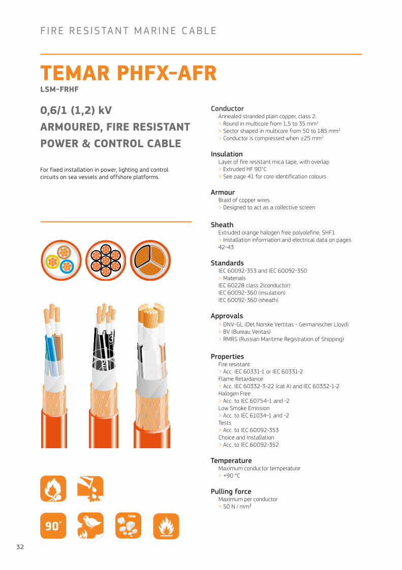
TEMAR PHFX-AFRLSM-FRHF
0,6/1 (1,2) kVARMOURED, FIRE RESISTANTPOWER & CONTROL CABLE
For fixed installation in power, lighting and control circuits on sea vessels and offshore platforms.
ConductorAnnealed stranded plain copper, class 2 .> Round in multicore from 1,5 to 35 mm2
> Sector shaped in multicore from 50 to 185 mm2
> Conductor is compressed when ≥25 mm2
InsulationLayer of fire resistant mica tape, with overlap> Extruded HF 90°C> See page 41 for core identification colours
ArmourBraid of copper wires> Designed to act as a collective screen
SheathExtruded orange halogen free polyolefine, SHF1> Installation information and electrical data on pages 42-43
StandardsIEC 60092-353 and IEC 60092-350> MaterialsIEC 60228 class 2(conductor)IEC 60092-360 (insulation)IEC 60092-360 (sheath)
Approvals> DNV-GL (Det Norske Vertitas - Germanischer Lloyd)> BV (Bureau Veritas)> RMRS (Russian Maritime Registration of Shipping)
PropertiesFire resistant > Acc . IEC 60331-1 or IEC 60331-2Flame Retardance > Acc . IEC 60332-3-22 (cat A) and IEC 60332-1-2Halogen Free > Acc . to IEC 60754-1 and -2Low Smoke Emission> Acc . to IEC 61034-1 and -2Tests> Acc . to IEC 60092-353Choice and Installation> Acc . to IEC 60092-352
TemperatureMaximum conductor temperature > +90 °C
Pulling forceMaximum per conductor > 50 N / mm²
90°low
32

Conductor cross-section mm
Earth wire version
Conductor heigth mm
Conductor width mm
Diameter over braid mm
Cable diameter mm
Cable weight kg /km
Bending radius, fixed mm
POWER CABLES
2x1,5 1,6 – 8,5 11,0 145 70
2x2,5 2,0 – 9,5 12,0 170 75
3x1,5 3G1,5 1,6 – 9,0 11,5 170 70
3x2,5 3G2,5 2,0 – 10,0 12,5 220 75
3x4 2,6 – 13,5 16,0 430 100
3x6 3,1 – 15,0 18,0 580 110
3x10 4,0 – 17,0 20,0 780 120
3x16 5,0 – 20,0 23,0 1070 140
3x25 5,8 – 25,0 28,5 1630 175
3x35 6,8 – 27,0 30,5 2060 190
3x50 6,5 10,7 27,0 30,5 2250 245
3x70 7,9 12,8 30,5 35,0 3040 280
3x95 9,3 15,1 34,0 39,0 4030 320
3x120 10,5 17,0 37,5 42,5 4920 340
3x150 11,6 18,9 41,0 44,5 5960 360
4x1,5 1,6 – 10,0 12,5 205 75
4x2,5 2,0 – 11,0 13,5 260 85
4x4 2,6 – 15,0 18,0 560 110
4x6 3,1 – 16,5 19,5 690 120
4x10 4,0 – 19,0 22,0 940 135
4x16 5,0 – 22,0 25,0 1290 150
4x25 5,8 – 27,0 31,0 1990 190
4x35 6,8 – 29,5 33,5 2540 200
4x50 7,2 9,9 30,5 35,0 2930 280
4x70 8,6 12,0 35,0 40,0 4010 320
4x120 11,5 15,8 42,5 48,0 6330 385
CONTROL CABLES
5x1,5 5G1,5 1,6 – 11,0 14,0 250 85
7x1,5 1,6 – 12,0 15,0 320 90
12x1,5 1,6 – 17,0 20,0 570 120
19x1,5 1,6 – 19,5 23,0 800 140
27x1,5 1,6 – 24,0 28,0 1100 170
5x2,5 2,0 – 12,0 15,0 320 90
7x2,5 2,0 – 14,0 16,5 460 100
12x2,5 2,0 – 19,0 22,0 740 130
19x2,5 2,0 – 22,0 26,0 1050 160
33
FIRE RESISTANT MARINE CABLE
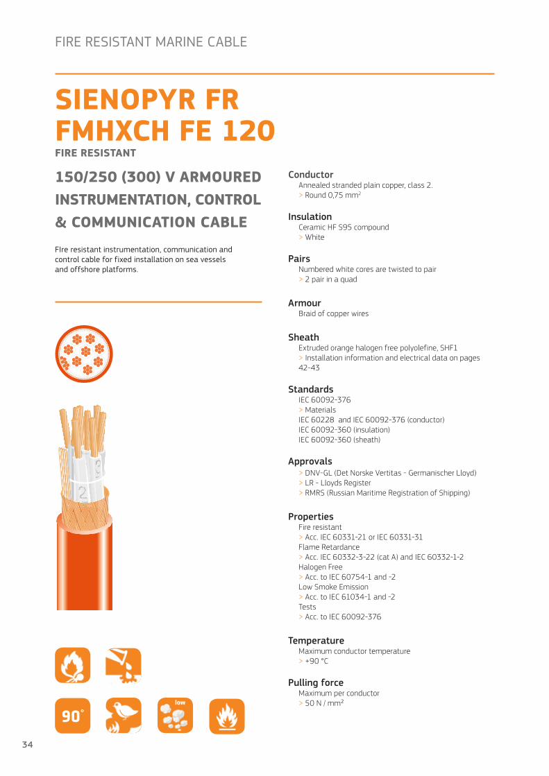
FIre resistant instrumentation, communication and control cable for fixed installation on sea vessels and offshore platforms.
SIENOPYR FR FMHXCH FE 120FIRE RESISTANT
150/250 (300) V ARMOUREDINSTRUMENTATION, CONTROL& COMMUNICATION CABLE
ConductorAnnealed stranded plain copper, class 2 .> Round 0,75 mm2
InsulationCeramic HF S95 compound> White
PairsNumbered white cores are twisted to pair> 2 pair in a quad
ArmourBraid of copper wires
SheathExtruded orange halogen free polyolefine, SHF1> Installation information and electrical data on pages 42-43
StandardsIEC 60092-376> MaterialsIEC 60228 and IEC 60092-376 (conductor)IEC 60092-360 (insulation)IEC 60092-360 (sheath)
Approvals> DNV-GL (Det Norske Vertitas - Germanischer Lloyd)> LR - Lloyds Register > RMRS (Russian Maritime Registration of Shipping)
PropertiesFire resistant > Acc . IEC 60331-21 or IEC 60331-31Flame Retardance > Acc . IEC 60332-3-22 (cat A) and IEC 60332-1-2Halogen Free > Acc . to IEC 60754-1 and -2Low Smoke Emission> Acc . to IEC 61034-1 and -2Tests> Acc . to IEC 60092-376
TemperatureMaximum conductor temperature > +90 °C
Pulling forceMaximum per conductor > 50 N / mm²
90°low
34
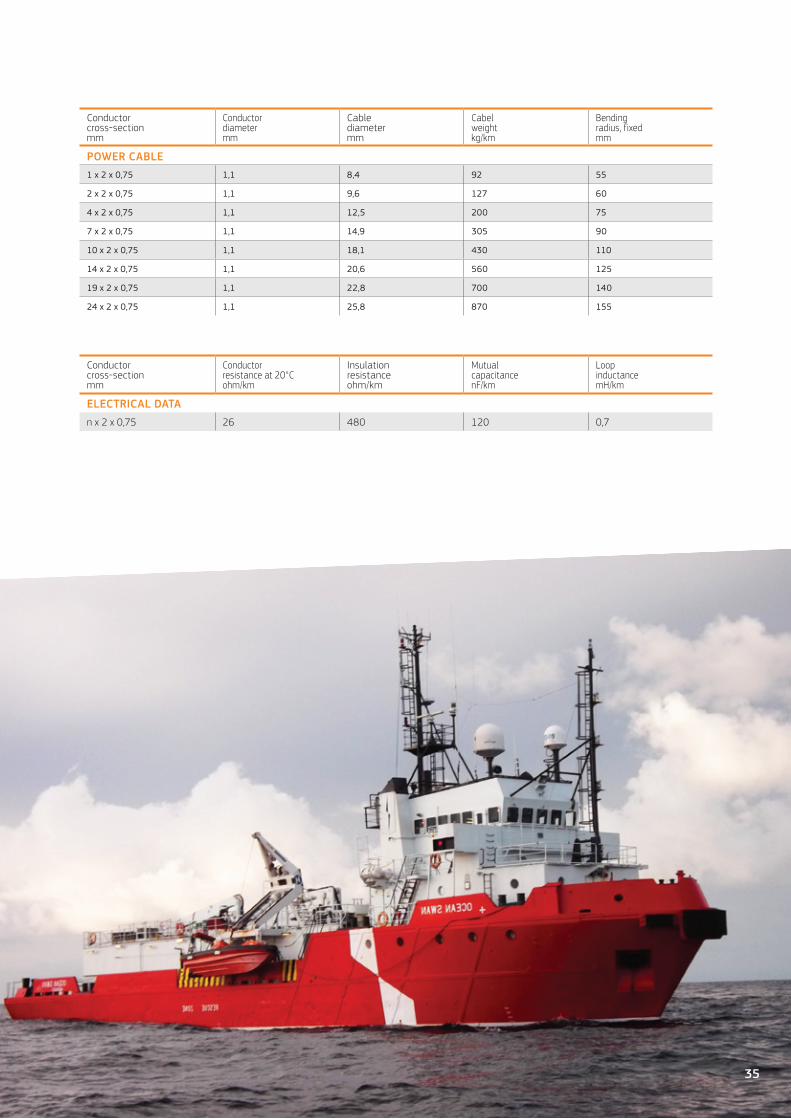
Conductor cross-section mm
Conductor diameter mm
Cable diameter mm
Cabel weight kg/km
Bending radius, fixedmm
POWER CABLE1 x 2 x 0,75 1,1 8,4 92 55
2 x 2 x 0,75 1,1 9,6 127 60
4 x 2 x 0,75 1,1 12,5 200 75
7 x 2 x 0,75 1,1 14,9 305 90
10 x 2 x 0,75 1,1 18,1 430 110
14 x 2 x 0,75 1,1 20,6 560 125
19 x 2 x 0,75 1,1 22,8 700 140
24 x 2 x 0,75 1,1 25,8 870 155
Conductor cross-section mm
Conductor resistance at 20°C ohm/km
Insulation resistance ohm/km
Mutual capacitance nF/km
Loop inductance mH/km
ELECTRICAL DATAn x 2 x 0,75 26 480 120 0,7
35

MEDIUM VOLTAGE M A R INE C A B L E
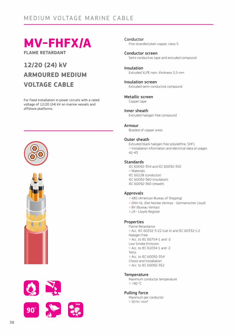
MV-FHFX/AFLAME RETARDANT
6/10 (12) kVARMOURED MEDIUMVOLTAGE CABLE
For fixed installation in power circuits with a rated voltage of 6/10 (12) kV on marine vessels and offshore platforms.
ConductorFine stranded plain copper, class 5 .
Conductor screenSemi-conductive tape and extruded compound
InsulationExtruded XLPE nom . thickness 3 .4 mm
Insulation screenExtruded semi-conductive compound
Metallic screenCopper tape
Inner sheathExtruded halogen free compound
Armour
Braided of copper wires
Outer sheathExtruded black halogen free polyolefine, SHF1> Installation information and electrical data on pages 42-43
StandardsIEC 60092-354 and IEC 60092-350> MaterialsIEC 60228 (conductor)IEC 60092-360 (insulation)IEC 60092-360 (sheath)
Approvals> ABS (American Bureau of Shipping)> DNV-GL (Det Norske Vertitas - Germanischer Lloyd)> BV (Bureau Veritas)> LR - Lloyds Register > RMRS (Russian Maritime Registration of Shipping)
PropertiesFlame Retardance > Acc . IEC 60332-3-22 (cat A) and IEC 60332-1-2Halogen Free > Acc . to IEC 60754-1 and -2Low Smoke Emission> Acc . to IEC 61034-1 and -2Tests> Acc . to IEC 60092-354Choice and Installation> Acc . to IEC 60092-352
TemperatureMaximum conductor temperature > +90°C
Pulling forceMaximum per conductor > 50 N / mm²
90°low
36
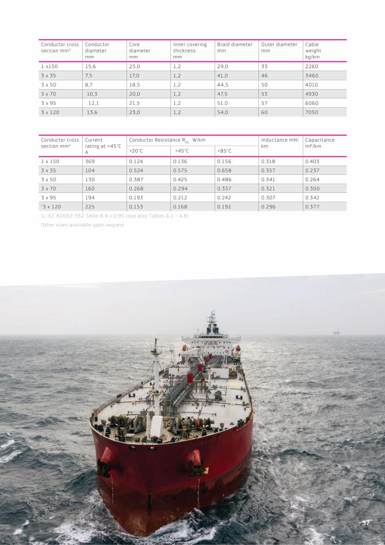
Conductor cross section mm2
Conductor diameter mm
Core diameter mm
Inner covering thickness mm
Braid diameter mm
Outer diameter mm
Cable weight kg /km
1 x150 15,6 25,0 1,2 29,0 33 2260
3 x 35 7,5 17,0 1,2 41,0 46 3460
3 x 50 8,7 18,5 1,2 44,5 50 4010
3 x 70 10,3 20,0 1,2 47,5 53 4930
3 x 95 12,1 21,5 1,2 51,0 57 6060
3 x 120 13,6 23,0 1,2 54,0 60 7050
Conductor cross section mm2
Current rating at +45"C A
Conductor Resistance RDC W/km Inductance mH/km
Capacitance mF/km
+20"C +45"C +85"C
1 x 150 369 0 .124 0 .136 0 .156 0 .318 0 .403
3 x 35 104 0 .524 0 .575 0 .658 0 .357 0 .237
3 x 50 130 0 .387 0 .425 0 .486 0 .341 0 .264
3 x 70 160 0 .268 0 .294 0 .337 0 .321 0 .300
3 x 95 194 0 .193 0 .212 0 .242 0 .307 0 .342
"3 x 120 225 0,153 0 .168 0 .192 0 .296 0 .377
1) IEC 60092-352 Table B .4 x 0,95 (see also Tables A .1 - A .8)
Other sizes available upon request
37
MEDIUM VOLTAGE M A R INE C A B L E
MV-FHFX/AFLAME RETARDANT
12/20 (24) kVARMOURED MEDIUMVOLTAGE CABLE
For fixed installation in power circuits with a rated voltage of 12/20 (24) kV on marine vessels and offshore platforms.
ConductorFine stranded plain copper, class 5 .
Conductor screenSemi-conductive tape and extruded compound
InsulationExtruded XLPE nom . thickness 5,5 mm
Insulation screenExtruded semi-conductive compound
Metallic screenCopper tape
Inner sheathExtruded halogen free compound
Armour
Braided of copper wires
Outer sheathExtruded black halogen free polyolefine, SHF1> Installation information and electrical data on pages 42-43
StandardsIEC 60092-354 and IEC 60092-350> MaterialsIEC 60228 (conductor)IEC 60092-360 (insulation)IEC 60092-360 (sheath)
Approvals> ABS (American Bureau of Shipping)> DNV-GL (Det Norske Vertitas - Germanischer Lloyd)> BV (Bureau Veritas)> LR - Lloyds Register
PropertiesFlame Retardance > Acc . IEC 60332-3-22 (cat A) and IEC 60332-1-2Halogen Free > Acc . to IEC 60754-1 and -2Low Smoke Emission> Acc . to IEC 61034-1 and -2Tests> Acc . to IEC 60092-354Choice and Installation> Acc . to IEC 60092-352
TemperatureMaximum conductor temperature > +90 °C
Pulling forceMaximum per conductor > 50 N / mm²
90°low
38

Conductor cross section mm2
Conductor diameter mm
Core diameter mm
Inner covering thickness mm
Braid diameter mm
Outer diameter mm
Cable weight kg /km
1 x 150 15,6 29,3 1,2 33,4 38 2670
3 x 35 7,5 21,2 1,2 51,3 58 4780
3 x 50 8,7 22,4 1,2 53,9 60 5450
Conductor cross section mm2
Current rating at +45"C A
Conductor Resistance RDC W/km Inductance mH/km
Capacitance mF/km
+20"C +45"C +85"C
1 x 150 369 0 .124 0 .136 0 .156 0,366 0,273
3 x 35 104 0 .524 0 .575 0 .658 0,395 0,169
3 x 50 130 0 .387 0 .425 0 .486 0,376 0,185
1) IEC 60092-352 Table B .4 x 0,95 (see also Tables A .1 - A .8)
Other sizes available upon request
39

GeneralThe rated voltage of a cable must not be lower than the nominal voltage of the circuit in which it is used . The ambient temperature during operation should be at least 10ºC lower than the maximum conductor temperature allowed to the insulation material .
Rated VoltageThe rated voltages of cables are expressed as Uo/U(Um) where: Uo the rated voltage between the conductor and earth, or between the conductor and the metal screen for which the cable is designed .
U the rated voltage between the conductors for which the cable is designed .
Um the highest system voltage for which the cables may be used
TECHNICALINFORMATION
Installation TemperatureThe minimum installation temperature for thermoplastic sheathed cables is –15°C . If, however, the cables are warmed up prior to installation, they can be installed at lower temperatures . Lowest operation temperature -40°C .
Earthing of BraidsEarthing of braids is to be carried out in accordance withthe regulations of the classification society .
Bending RadiusThe minimum bending radii according to IEC 60092-352in the final fixed assembly:
During installation the recommended radius is 1,5 timesthe value given in the table . Maximun pulling tension P = 50 N/mm2 x total conductor cross section mm2 value of the cable .
Insulation material
Outer covering
Outer cable diamter
Bending radius
Thermoplastic or thermo- setting with circular copper conductors
Unarmoured ≤25 mm 4 x D
Armoured > 25 mm 6 x D
Metal braid screened or armoured
Any 6 x D
Armoured with metal wire, tape or sheath
Any 6 x D
Composite polyester or metal laminate screened units or collective tape screening
Any 8 x D
Thermoplastic or thermo-setting with shaped copper conductors
Any Any 8 x D
Medium voltage cables
AnySingel-core 12 x D
3-core 9 x D
40
1 2 3
123 1 2 3
123
1 2 3
123
1 2 3
1231 2 3
123
1
2
3
1
2
3
1
2
3
1
2
3
1
2
3
1
2
3
1
2
3
1
2
3
1
2
3
1
2
3
1
2
3
1
2
3
1
2
3
1
2
3
1
2
3
1
2
3
1
2
3
1
2
3
1
2
3
1
2
3
21 3
213
1 12 23 3
1 2 3
123
Or
Or
Four cables per phase
Six cables per phase
Ten cables per phase on the same cable tray
TECHNICALINFORMATION
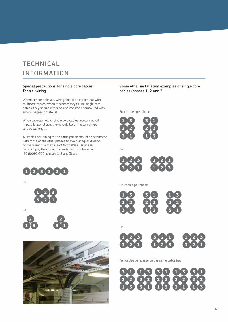
Special precautions for single core cablesfor a.c. wiring.
Whenever possible, a .c . wiring should be carried out withmulticore cables . When it is necessary to use single core cables, they should either be unarmoured or armoured witha non-magnetic material .
When several multi or single core cables are connectedin parallel per phase, they should be of the same typeand equal length .
All cables pertaining to the same phase should be alternatedwith those of the other phases to avoid unequal divisionof the current . In the case of two cables per phase,for example, the correct dispositions to conform withIEC 60092-352 (phases 1, 2 and 3) are:
Some other installation examples of single corecables (phases 1, 2 and 3).
Or
Or
41

CURRENT RATING
Current rating for continuous service. Conductor temperature max. +90˚C, ambient max +45˚C. According to IEC 60092-352, Table B.4 for 0,6/1 kV cables. Up to 6 cables bunched together.
Cores 1 2 3 4 5 7 12 19 27 37
Reduction 1,00 0,85 0,70 0,70 0,58 0,52 0,44 0,37 0,33 0,30
Cros
s-se
ctio
n
(мм²) (A) (A) (A) (A) (A) (A) (A) (A) (A) (A)
1,5 23 20 16 16 13 12 10 9 8 7
2,5 30 26 21 21 18 16 13 11 10 9
4 41 34 28 28 24
6 52 44 36 36 30
10 72 61 50 50 42
16 96 82 67 67 56
25 127 108 89 89 74
35 157 133 110 110 92
50 196 167 137 137
70 242 206 169 169
95 293 249 205 205
120 339 288 237 237
150 389 331 272 272
185 444 377 311 311
240 522 444 365 365
300 601 511 421 421
Ambient temperature correction factors According to IEC 60092-352
Тemperature (˚C) 35 40 45 50 55 60 65 70 75
Correction factor 1,10 1,05 1,00 0,94 0,88 0,82 0,74 0,67 0,58
42
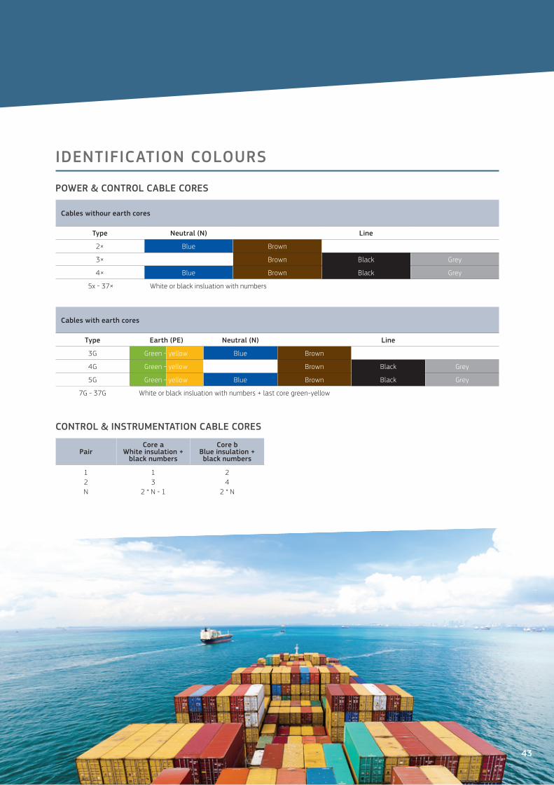
IDENTIFICATION COLOURS
Cables withour earth cores
Type Neutral (N) Line
2× Blue Brown
3× Brown Black Grey
4× Blue Brown Black Grey
5x - 37× White or black insluation with numbers
Cables with earth cores
Тype Earth (PE) Neutral (N) Line
3G Green - yellow Blue Brown
4G Green - yellow Brown Black Grey
5G Green - yellow Blue Brown Black Grey
7G - 37G White or black insluation with numbers + last core green-yellow
PairCore a
White insulation + black numbers
Core b Blue insulation + black numbers
12N
13
2 * N - 1
24
2 * N
POWER & CONTROL CABLE CORES
CONTROL & INSTRUMENTATION CABLE CORES
43

Cable type TEMAR PHFX
-U, -A, -UFR, -AFR(n x mm²)
Cross-section (mm²)
Сonductor Resistance acc. to IEC 60228 class 2. R (Ω/км) Inductance
L(mн/км)
at +20˚C at +45˚C at +85˚C
1×35 35 0,524 0,575 0,658 0,316
1×50 50 0,387 0,425 0,486 0,315
1×70 70 0,268 0,294 0,336 0,303
1×95 95 0,193 0,212 0,242 0,292
1×120 120 0,153 0,168 0,192 0,284
1×150 150 0,124 0,136 0,156 0,286
1×185 185 0,0991 0,109 0,124 0,281
1×240 240 0,0754 0,083 0,095 0,276
1×300 300 0,0601 0,066 0,075 0,288
2×1,5 1,5 12,1 13,289 15,191 0,336
2×2,5 2,5 7,41 8,138 9,303 0,313
3×1,5 1,5 12,1 13,289 15,191 0,336
3×2,5 2,5 7,41 8,138 9,303 0,313
3×4 4 4,61 5,063 5,788 0,293
3×6 6 3,08 3,383 3,867 0,281
3×10 10 1,83 2,010 2,297 0,266
3×16 16 1,15 1,263 1,444 0,254
3×25 25 0,727 0,798 0,913 0,211
3×35 35 0,524 0,575 0,658 0,202
3×50 50 0,387 0,425 0,486 0,200
3×70 70 0,268 0,294 0,336 0,197
3×95 95 0,193 0,212 0,242 0,190
3×120 120 0,153 0,168 0,192 0,189
3×150 150 0,124 0,136 0,156 0,191
3×185 185 0,0991 0,109 0,124 0,193
3×240 240 0,0754 0,083 0,095 0,190
3×300 300 0,0601 0,066 0,075 0,188
4×1,5 1,5 12,1 13,289 15,191 0,359
4×2,5 2,5 7,410 8,138 9,303 0,336
4×4 4 4,61 5,063 5,788 0,317
4×6 6 3,08 3,383 3,867 0,304
4×10 10 1,83 2,010 2,297 0,289
4×16 16 1,15 1,263 1,444 0,278
4×25 25 0,727 0,798 0,913 0,267
4×35 35 0,524 0,575 0,658 0,258
4×50 50 0,387 0,425 0,486 0,217
4×70 70 0,268 0,294 0,336 0,213
4×95 95 0,193 0,212 0,242 0,206
4×120 120 0,153 0,168 0,192 0,205
4×150 150 0,124 0,136 0,156 0,209
4×185 185 0,0991 0,109 0,124 0,209
4×240 240 0,0754 0,083 0,095 0,206
4×300 300 0,0601 0,066 0,075 0,204
ELECTRICAL DATA
44
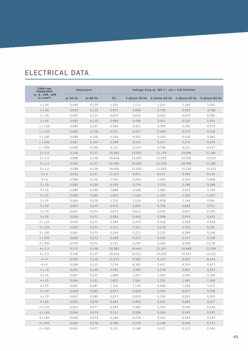
ELECTRICAL DATA
ELECTRICAL DATA
Cable type TEMAR PHFX
-U, -A, -UFR, -AFR(n x mm²)
Reactance Voltage Drop at +85°C - cos = 0,8 (mV/Am)
at 50 Hz at 60 Hz DC 1-phase 50 Hz 3-phase 50 Hz 1-phase 60 Hz 3-phase 60 Hz
1 x 35 0,099 0,119 1,316 1,172 1,015 1,195 1,035
1 x 50 0,099 0,119 0,972 0,896 0,776 0,920 0,796
1 x 70 0,095 0,114 0,673 0,653 0,565 0,675 0,585
1 x 95 0,092 0,110 0,485 0,498 0,431 0,520 0,450
1 x 120 0,089 0,107 0,384 0,415 0,359 0,436 0,378
1 x 150 0,090 0,108 0,311 0,357 0,309 0,379 0,328
1 x 185 0,088 0,106 0,249 0,305 0,264 0,326 0,282
1 x 240 0,087 0,104 0,189 0,255 0,221 0,276 0,239
1 x 300 0,090 0,108 0,151 0,229 0,198 0,251 0,217
2 x 1,5 0,106 0,127 30,382 24,432 21,159 24,458 21,181
2 x 2,5 0,098 0,118 18,606 15,003 12,993 15,026 13,013
3 x 1,5 0,106 0,127 30,382 24,432 21,159 24,458 21,181
3 x 2,5 0,098 0,118 18,606 15,003 12,993 15,026 13,013
3 x 4 0,092 0,111 11,575 9,371 8,115 9,393 8,135
3 x 6 0,088 0,106 7,734 6,293 5,450 6,314 5,468
3 x 10 0,083 0,100 4,595 3,776 3,270 3,796 3,288
3 x 16 0,080 0,096 2,888 2,406 2,084 2,425 2,100
3 x 25 0,066 0,080 1,825 1,540 1,334 1,556 1,347
3 x 35 0,064 0,076 1,316 1,129 0,978 1,144 0,991
3 x 50 0,063 0,075 0,972 0,853 0,738 0,868 0,751
3 x 70 0,062 0,074 0,673 0,612 0,530 0,627 0,543
3 x 95 0,060 0,072 0,485 0,459 0,398 0,474 0,410
3 x 120 0,059 0,071 0,384 0,379 0,328 0,393 0,340
3 x 150 0,060 0,072 0,311 0,321 0,278 0,335 0,291
3 x 185 0,061 0,073 0,249 0,272 0,235 0,286 0,248
3 x 240 0,060 0,072 0,189 0,223 0,193 0,237 0,206
3 x 300 0,059 0,071 0,151 0,192 0,166 0,206 0,178
4 x 1,5 0,113 0,136 30,382 24,441 21,167 24,468 21,190
4 x 2,5 0,106 0,127 18,606 15,011 13,000 15,037 13,022
4 x 4 0,099 0,119 11,575 9,380 8,123 9,403 8,144
4 x 6 0,096 0,115 7,734 6,302 5,457 6,324 5,477
4 x 10 0,091 0,109 4,595 3,785 3,278 3,807 3,297
4 x 16 0,087 0,105 2,888 2,415 2,091 2,436 2,109
4 x 25 0,084 0,101 1,825 1,561 1,352 1,581 1,369
4 x 35 0,081 0,097 1,316 1,150 0,996 1,169 1,013
4 x 50 0,068 0,082 0,972 0,859 0,744 0,875 0,758
4 x 70 0,067 0,080 0,673 0,619 0,536 0,635 0,550
4 x 95 0,065 0,078 0,485 0,465 0,403 0,481 0,417
4 x 120 0,064 0,077 0,384 0,385 0,333 0,400 0,346
4 x 150 0,066 0,079 0,311 0,328 0,284 0,343 0,297
4 x 185 0,066 0,079 0,249 0,278 0,241 0,294 0,254
4 x 240 0,065 0,078 0,189 0,229 0,198 0,245 0,212
4 x 300 0,064 0,077 0,151 0,198 0,171 0,213 0,184
45

Prysmian Group Denmark A/SRoskildevej 222620 AlbertslundDenmark
Sales +45 60 39 27 39 +45 60 39 26 29
Prysmian Group Finland OyKaapelitie 6802490 Pikkala Johdintie 5 90620 Oulu
Sales +35 010 5661
Prysmian Group Sweden ABVallgatan 557141 NässjöSweden
Sales+46 38 055 42 09 +46 38 055 42 08
[email protected] [email protected] [email protected]
Prysmian Group Norway AS Postboks 369 Bragernes 3001 Drammen Norway
Sales +47 32 24 90 00
no-kundesenter@ prysmiangroup.com
Prysmian Group Estonia AS Paldiski mnt. 31 76606 Keila Estonia
Sales +371 9272 731 (Latvia) +370 6 187 4 384 (Lithuania)
www.prysmiangroup.dk
www.prysmiangroup.fi www.draka.se www.prysmiangroup.no www.drakakeila.ee
Linking the future