marconi - american radio history: documents from the ... · marconi roa casting division 500kw...
TRANSCRIPT

Marconi
roa casting Division
500kW Shortwave Broadcast Transmitter
B6127
Features Pulsam low loss modulator
High -efficiency at average modulation levels
Clean 100% modulation of positive and negative peaks
Low level spurious radiation
Fast frequency change for up to 128 pre -set channels
Rapid tube changing
Good accessibility for maintenance
Simple tube protection
Condensed vapour cooling
Exceptionally stable and cool running
Stored fault indications
Diagnostic I.e.d panel
Auto matching for varying antenna v.s.w.r
12 pulse silicon diode rectification
Suitable for extended, remote or microprocessor control
Full protection of personnel and equipment
Low ownership costs
Introducing the Pulsam 500kW Transmitter The Marconi B6127 transmitter is the most technologically advanced and the least costly to operate in its class.
The new PULSAM low loss modulation system of amplitude modulation combines the virtues of pulse width and Class B
modulation resulting in a transmitter which is psychologically acceptable to maintenance personnel in addition to its many other special features.
B6127
Audio
60011 balanced audio
I input I
L
processing Switching
1JV tubes
and diodes inductor nn Storage
Pulsam modulator
J
1
/ /nn 2xTH 581 Low pass
tpr
fin Synthesized
r.f drive unit
Frequency
Broadband I
amplifier
Drive level
Local control Frequency
control Remote memory unit control
Local control
Remote control
Manual control
Penultimate r.f stage
(4CW 25000A)
I -
r
Final r.f stage (TH558)
TV filter 40-- 250MHz
Balun -- (optional) Reflectometer 75R 30011
Trip and overload sensing circuits
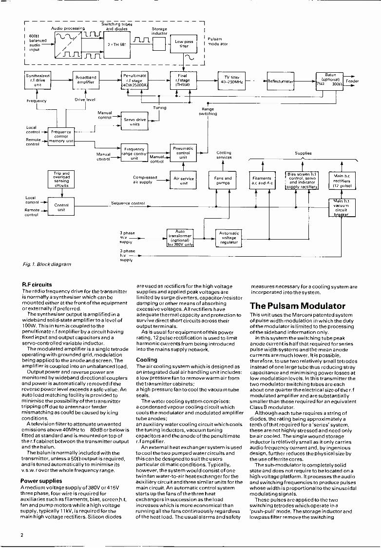
Fig. 1. Block diagram
Servo drive units
Manual control
--II' Frequency
range control unit
Tuning T Range
switching
Pneumatic - control -0- Cooling Manual-o. unit services control
Compressed Air service air supply unit
Sequence control s
3 phase m.v supply
Fans and pumps 1
Supplies
Feeder
1
Bias screen h.t Filaments control, servo a.c and d.c and indicator
su..ly rectifiers
Auto transformer (optional) T Automatic
voltage regulator
for 380V only
3 phase h.v supply
R.F circuits The radio frequency drive for the transmitter is normally a synthesiser which can be mounted either at the front of the equipment or externally if preferred.
The synthesiser output is amplified in a wideband solid -state amplifier to a level of 100W. This in turn is coupled to the penultimate r.f amplifier by a circuit having fixed input and output capacitors and a servo -controlled variable inductor.
The modulated amplifier is a single tetrode operating with grounded grid, modulation being applied to the anode and screen. The amplifier is coupled into an unbalanced load.
Output power and reverse power are monitored by wideband directional couplers and power is automatically removed if the reverse power level exceeds a safe value. An auto load matching facility is provided to minimise the possibility of the transmitter tripping off due to antenna or feeder mismatching as could be caused by icing conditions.
A television filter to attenuate unwanted emissions above 40MHz to -80dB or below is fitted as standard and is mounted on top of the r.f cabinet between the transmitter output and the balun.
The balun is normally included with the transmitter, unless a 5012 output is required, and is tuned automatically to minimise its v.s.w.r over the whole frequency range.
Power supplies A medium voltage supply of 380V or 415V three phase, four wire is required for auxiliaries such as filaments, bias, screenh.t, fan and pump motors while a high voltage supply, typically 11 kV, is required for the main high voltage rectifiers. Silicon diodes
2
are used as rectifiers for the high voltage supplies and applied peak voltages are limited by surge diverters, capacitor /resistor damping or other means of absorbing excessive voltages. All rectifiers have adequate thermal capacity and protection to survive direct short circuits across their output terminals.
As is usual for equipment of this power rating, 12 pulse rectification is used to limit harmoniccurrentsfrom being introduced into the mains supply network.
Cooling The air cooling system which is designed as an integrated dual air handling unit includes: a low pressure fan to remove warm air from the transmitter cabinets; a high pressure fan to cool the vacuum tube seals.
The water cooling system comprises: a condensed vapour cooling circuit which cools the modulator and modulated amplifier tube anodes; an auxiliary water cooling circuit which cools thetuning inductors, vacuum tuning capacitors and the anode of the penultimate r.f amplifier.
An external heat exchanger system is used to cool the two pumped water circuits and this can be designed to suit the users particular climatic conditions. Typically, however, the system would consist of one twin fan water -to -air heat exchanger for the auxiliary circuit and three similar units for the main circuit. An automatic control system starts up the fans of the three heat exchangers in succession as the load increases which is more economical than running all the fans continuously regardless of the heat load. The usual alarms and safety
measures necessary fora cooling system are incorporated into the system.
The Pulsam Modulator This unit uses the Marconi patented system of pulse width modulation in which the duty of the modulator is limited to the processing of the sideband information only.
In this system the switching tube peak anode current is half that required for series pulse width systems and the mean anode currents are much lower. It is possible, therefore, to use two relatively small tetrodes instead of one large tube thus reducing stray capacitance and minimising power losses at low modulation levels. In this transmitter the two modulator switching tubes are each about one quarter the electrical size of the r.f modulated amplifier and are substantially smaller than those required for an equivalent Class B modulator.
Although each tube requires a string of diodes, the rating being approximately a tenth of that required for a 'series' system, these are not highly stressed and need only be air cooled. The single wound storage inductor is relatively small as it only carries audio frequency current and, by ingenious design, further reduces the physical size by the use of ferrite cores.
The sub-modulator is completely solid state and does not require to be located on a high voltage platform. It processes the audio and switching frequencies to produce pulses whose width is proportional to the sinusoidal modulating signals.
These pulses are applied to the two switching tetrodes which operate in a 'push -pull' mode. The storage inductor and lowpass filter remove the switching
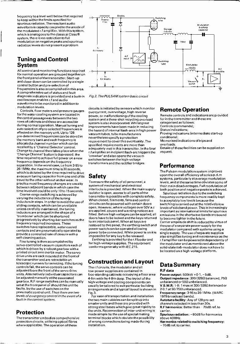
frequency to a level well below that required to keep within the limits specified for spurious radiation. The resultant audio waveform is capacity coupled to the anode of the modulated r.f amplifier. With this system, which is analogous to the classical Class B
system, there is no restriction to full modulation on negative peaks and spurious radiation levels do not present a problem.
Tuning and Control System All control and monitoring functions required for normal operation are grouped together on the front panel of the transmitter. Start-up and close -down can be controlled by a single control button and pre -selection of frequencies is also accomplished in this area. A comprehensive set of status and fault diagnosis indicators is provided and a built -in oscilloscope enables r.f and audio waveforms to be monitored in addition to modulation levels.
Controls, flow meters and pressure gauges for the water cooling system are located in the central passageway between the two rows of cabinets and these are accessible during normal operation. Manual tuning and auto selection of pre -selected frequencies is effected on the memory unit. Up to 128 pre- determined frequencies can be stored in the memory bank and each frequency is allocated a channel number which can be recalled by a 'Channel Selector' control. Change to channel then takes place when the 'Change Channel' button is depressed. the time required to achieve full power on a new frequency depends on the frequency separation. In the worst case, i.e from 3.95 to 26.1 MHz, the maximum time is 30 seconds, which is dictated by the time required to drive a vacuum tuning capacitor from one end of its travel to the other without undue wear. Ir practice most frequency changes are usually between adjacent bands in which case the time involved could be only 10to 15 seconds.
Coarse range switching is achieved by varying the inductance of the tuning inductors in steps. In order to avoid the use of sliding contacts, which can be unreliable unless carefully maintained, the tuning inductors are arranged in the shape of a
'trombone' which can be shortened progressively by shorting -bar switches as the frequency required increases. These switches have replaceable, water cooled contacts and are pneumatically operated to provide a controlled rate of closure with a
self -cleaning action. Fine tuning is then accomplished by
servo -controlled vacuum capacitors each of which is driven by a robust gearbox with a printed circuit zero inertia motor. The servo drive units are rack mounted at the front of the transmitter and are retractable on telescopic runners for servicing. If the tuning controls fail, the servo controls can be adjusted from the front of the servo drive units. Alternatively individual capacitors can be adjusted manually at the associated gearbox. R.F range switches can be manually set at the front panel or should this unit be faulty, by the use of switches on the pneumatic control unit. Thus there are two levels of emergency control in the event of a fault in the control system.
Protection The transmitter embodies comprehensive protection circuits, utilising optical fibres where applicable. The operation of these
Diodes
Supply filter
d c supply
o
a
E, d supply
AF input nZ
Switching tube
Fig.2. The PULSAM system basic circuit
Storage Inductor
Filter - NEB
Switching tube
circuits is initiated by sensors which monitor overcurrent, overvoltage, high reverse power, or malfunctioning of the cooling system and a three -shot recycling overload system is also incorporated. Whilst great improvements have been made in reducing the hazard of internal flash -arcs in high power vacuum tubes, tube manufacturers nevertheless specify a protection requirement to cover this eventuality. The specified requirements are more than adequately met in this transmitter. In the final r.f amplifier an incipient flash -arc triggers the 'crowbar' and also opens the vacuum switches between the high -voltage transformers and the rectifier bridges.
Safety To ensure the safety of all personnel,a system of mechanical and electrical interlocks is provided. When the main supply isolator is open, access to all parts of the transmitter is possible with complete safety. When closed, filaments, fans and control circuits can be powered with certain doors open. However, where voltages over 50V a.c are applied, covers and warning notices are fitted. Before high voltages can be applied, all doors have to be locked and the keys returned to an interlock panel. When all keys are restored to this panel, the earthing switch and power switch can be operated allowing power to be connected. While power is on it is impossible for any key to be released.
Earthing is provided for the r.f feeder and for high -voltage supplies. The equipment conforms generally with IEC.215.
Construction and Layout The r.f circuits, the modulator and all low -power supplies are contained in free -standing cabinets occupying a floor area 4.6m wide by 4.8m deep. The layout of the high voltage and cooling components can usually be tailored to suit particular building arrangements and a typical layout is shown in Fig.3.
For ease of transportation and installation the two main cubicles can be split up into smaller units and these are provided with strong steel bases which give great rigidity to the units. Reconnection of inter -unit wiring is made simple by the use of special mating terminal blocks which obviate the possibility of wrong connections being made during installation.
Modulation blocking capacitor
Modulation reactor
Vacuum switch
E,
Fi F
amplifier
D T1
Remote Operation Remote controls and indications are provided for in the transmitter and these are categorised as follows: Controls (commands); Status indications; Proving indications (intermediate start-up conditions); Memorised indications of trips and overloads. Details of these facilities can be supplied on request.
Performance The Pulsam modulation system improves upon the overall efficiency of series p.d.m systems, particularly at average modulation levels, and at the same time obviates some of their main disadvantages. Full modulation of both positiveand negative peaks is achieved.
Spurious radiation due to the switching frequency components is more readily kept to acceptably low levels because the switching is carried out at the relatively low levels of sideband power. This is increasingly important as international limits for spurious emissions in the shortwave bands are bound to become tighter in the future. Carrier amplitude shift is reduced by virtue of the use of a separate power supply for the modulator compared with systems using a
single supply. The use of separate supplies also simplifies tuning and maintenance as the r.f amplifier can be powered independently of the modulator and as mentioned above the solid -state sub -modulator does not have to be located on a high -voltage platform.
Data Summary R.F data Power output: 500kW +0.1, -5dB. Output impedance: 300/32812 balanced, 7552 unbalanced or 5012 unbalanced. V.S.W.R: 1.8: 1 max at 300/32812 balanced or 2-0:1 at50 /7512unbalanced. Frequency range: 3.95 to 26.1 MHz. (WARC 1979 broadcast bands). Autotunefacility: Any of 128 pre -set channels selected in less than 30s. R.F harmonics: Better than -70dB ref. to carrier. Spurious radiation: -80dB for harmonics above 40MHz. Harmonics related to switching frequency: -70dB ref. to carrier.
3

Broadcastingtivision Modulation data A.F input impedance: 60012 balanced. A.F input level: -5to +10dB for 40% modulation at 400Hz. A.F input attenuator: Range of 19.5dB in 0.5dB steps. A.F response: 60-6000Hz; +0.5, -1.0dB. 6000- 7500Hz; +0.5, -2.0dB relative to 400Hz at 75% modulation. A.F distortion: Less than 3 %t.h.dat50% modulation (60- 7500Hz); less than 4% t.h.d at 75% modulation (6000- 7500Hz); less than 4% t.h.d at 90% modulation (60- 6000Hz). Carrier noise: At least 56dB below 100% modulation at 400Hz. Modulation capability: 100% modulation for 10 min per hour then 70% modulation for 50 min per hour (with sinewave 60- 5000Hz) or 75% modulation continuously (with sinewave 60- 5000Hz).
Electrical data Power supplies: Auxiliary circuits 380/415V 3
phase 4 wire 50 /60Hz main rectifiers nominally 11 kV 3 phase (other supply voltages to order). Voltage fluctuation (permissible): Auxiliary circuits ±-10% main rectifiers adjustable +5% to -10% in steps. Full performance except power output, with maximum voltage variations of ±2 %. Frequency tolerance: ±2Hz. Line inbalance (permissible): Not greater than ±1°/ forfull performance. Power factor: Better than 0.9.
Environmental data Ambient temperature: 50 °C maximum*. Daily average: 45 °C. Yearly average: 35 °C. Altitude: 2300m maximum. Humidity: 95% maximum. *External cooling equipment can be designed for particular conditions including temperatures belotvfreezing point.
Overall efficiency: Better than 62% at any depth of modulation. Dimensions: See typical layout.
Marconi Communication Systems Broadcasting Division Chelmsford, England CM1 1PL Telephone 0245 353221 Telex 99201 Telegrams Expanse Chelmsford Telex
t 9 9 t
5.0 .1 30
46
Fig.3. Typical transmitter layout
©1982 The Marconi Company Limited Printed in England by Lund Humphries 141082/2500 +3000
This document gives only a general description of the product(s) and shall not form part of any contract. From time to time changes may be made in the products or in the conditions of supply.
1. Control and monitoring units 2. Pulsam modulator 3. Auxiliary power supplies 4. R.F unit 5. TV filter 6. Balun 7. 30011 trunk feeder 8. Passageway 9. Interlocked access door
10. Earthing switch
Dimensions in metres
1

Marconi Communication Systems
300kW H.F Broadcasting Transmitter
B6126
Advantages High Efficiency at all modulation levels
Low Operating and maintenance costs Low tube cost Rapid tube changing
Dual source tubes and high voltage components Exceptionally stable and cool running
Complete protection of personnel and equipment Good accessibility Suitable for extended, remote or microprocessor control
MI BROADCASTING DIVISION
Features Pulse width modulation
Advanced Pulsam low loss modulator
Very low level spurious radiation
No moving high power r.f contacts on power
Frequency follow (transmitter automatically powers at any drive frequency)
Automatching for varying v.s.w.r
Automatic progressive power reduction into load v.s.w.r's up to 4:1
Condensed vapour cooling
Comprehensive diagnostic I.e.d's
Stored fault indications
Status and fault indications can be remotely displayed
B6126
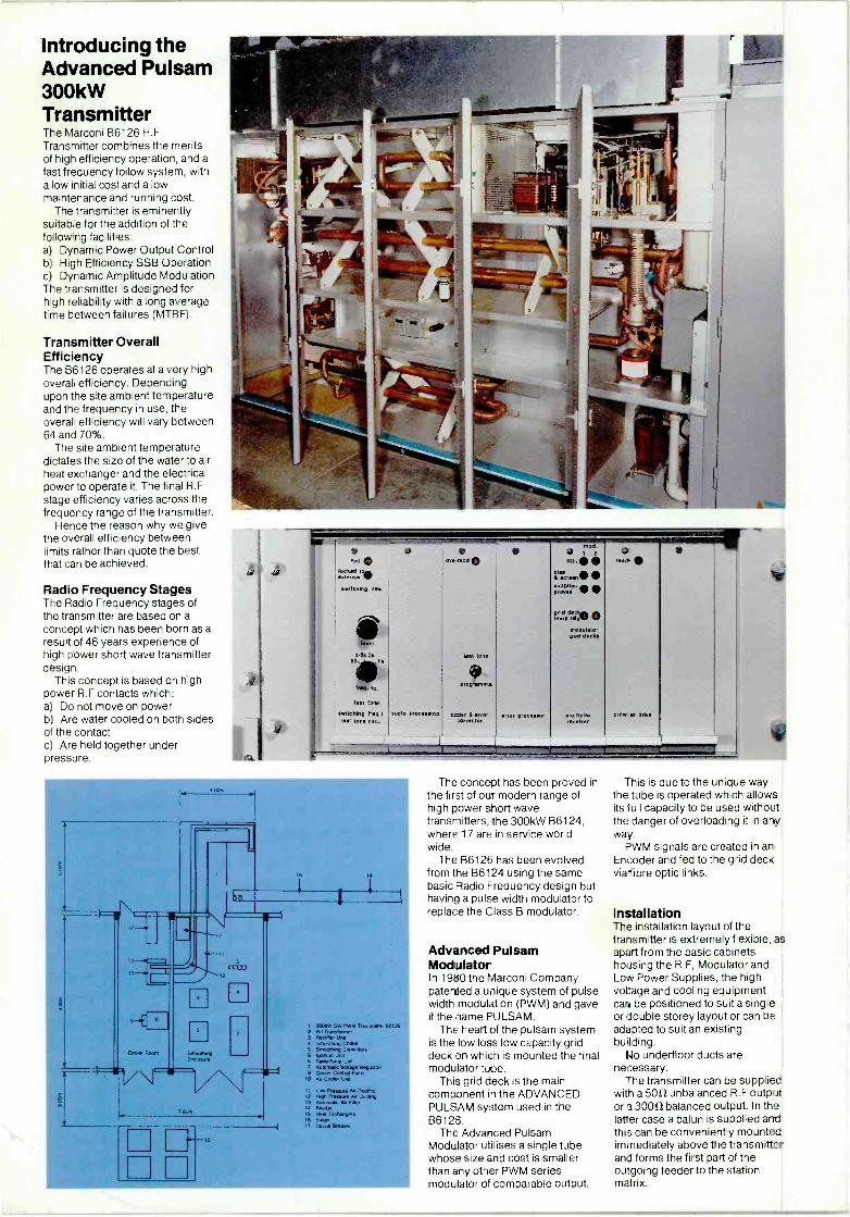
Introducing the Advanced Pulsam 300kW Transmitter The Marconi B6126 H.F Transmitter combines the merits of high efficiency operation, and a
fast frequency follow system, with a low initial cost and a low maintenance and running cost.
The transmitter is eminently suitable for the addition of the following facilities: a) Dynamic Power Output Control b) High Efficiency SSB Operation c) Dynamic Amplitude Modulation The transmitter is designed for high reliability with a long average time between failures (MTBF).
Transmitter Overall Efficiency The B6126 operates at a very high overall efficiency. Depending upon the site ambient temperature and the frequency in use, the overall efficiency will vary between 64 and 70 %.
The site ambient temperature dictates the size of the water to air heat exchanger and the electrical power to operate it. The final R.F stage efficiency varies across the frequency range of the transmitter.
Hence the reason why we give the overall efficiency between limits rather than quote the best that can be achieved.
Radio Frequency Stages The Radio Frequency stages of the transmitter are based on a
concept which has been born as a
result of 46 years experience of high power short wave transmitter design.
This concept is based on high power R.F contacts which: a) Do not move on power b) Are water cooled on both sides of the contact c) Are held together under pressure.
r a s:1 ©
=AD wncemg re.
level
., 1 5k ";k Balk
freq.-1z .
test tane
switching (-erg / bet tone cece
Sodio processing
uve mod
test tone
0 prom.
°der 6 error = orrector
error processor
nu.
bias screen s P%1 d gr d
ten P. tdeo V modulator
g =d decks
mu lipbx re. ewer
road
crow ar drive
1-1. nt7
V \ 780m
1 300kW SW PWM TrenanRler 06126 2 MC Transformer 3 Necteier Und 4 Smoothing Choke s SmootAeg Depeceors 6 l9neron Uni( 6 TanWPorrq, Unit > Automx4c 00le9e fiegolmcr 9 Coder Control Panel
to Air coder Unit
11 Low Pressure 00 Du 1.+g 12 KO Pressure Air Do°eng 13 Automalis Air Filter se Feeder 15 Exchangers 16 Baken 17 Circuit Breaker
The concept has been proved in the first of our modern range of high power short wave transmitters, the 300kW 86124, where 17 are in service world wide.
The B6126 has been evolved from the B6124 using the same basic Radio Frequency design but having a pulse width modulator to replace the Class B modulator.
Advanced Pulsam Mod JIator In 1980 the Marconi Company patented a unique system of pulse width modulation (PWM) and gave it the name PULSAM.
The heart of the pulsam system is the low loss low capacity grid deck on which is mounted the final modulator tube.
This grid deck is the main component in the ADVANCED PULSAM system used in the B6126.
The Advanced Pulsam Modulator utilises a single tube whose size and cost is smaller than any other PWM series modulator of comparable output.
This is due to the unique way the tube is operated which allows its full capacity to be used without the danger of overloading it in any way.
PWM signals are created in an Encoder and fed to the grid deck via fibre optic links.
Installation The installation layout of the transmitter is extremely flexible, as apart from the basic cabinets housing the R.F, Modulator and Low Power Supplies, the high voltage and cooling equipment cari be positioned to suit a single or double storey layout or can be adapted to suit an existing building.
No underfloor ducts are necessary.
The transmitter can be supplied with a 5012 unbalanced R.F output or a 3001/ balanced output. in the latter case a balun is supplied and this can be conveniently mounted immediately above the transmitter and forms the first part of the outgoing feeder to the station matrix.

Description R.F Circuits The radio frequency drive for the transmitter is normally a synthesiser, type H1542, which can be mounted either at the front of the equipment or externally if preferred. Provision is made for using an external frequency standard of 1 MHz. When this is used the internal standard will act as an automatic standby to the external standard.
The synthesiser output level of 100 milliwatts is raised to 100 watts by a wideband solid state amplifier covering the frequency range 3.95 to 26 1 MHz.
The wideband amplifier is coupled to the penultimate r.f stage by a circuit having fixed input and output capacitors, and a
servo controlled variable inductor. The penultimate stage, utilising a water cooled tetrode type
4CW25000A, is situated immediately below the output stage. This allows short connection paths to the final stage to be achieved. The coupling circuit utilises a water cooled inductor and pneumatically actuated off load r.f switches similar in principle to the high power circuits. Naturally cooled servo controlled variable vacuum capacitors are used in the coupling circuit.
The radio frequency output stage uses a TH537 tetrode which, although physically small, has an anode dissipation rating far in
excess of that required when the stage is fully modulated. This is achieved by'Hypervapotron' cooling of the anode. Dissipation per unit area of the grids can also be much higher than for conventional tubes by using pyrolytic graphite grids. These are
formed by oriented graphite and provide an unusually high heat transfer to the support structure. Mechanically the grids are robust, improving their strength as the grids warm up. Their secondary emission is lower than that of wire grids and the relatively lower working temperature reduces primary emission due to deposition of the cathode material.
The tuning inductors are of novel construction and are formed from lengths of straight copper tubing folded into an ideal mechanical arrangement for each circuit. The fixed contacts of the off load switches appear on one face of the folded inductor. The inductor section beyond the fold is only active for the lowest frequency range. This results in extremely small frame return path inductance between input and output circuit capacitors.
Cooling water is passed through the inductor copper pipes, which also serve as a distribution main for the water cooled capacitors. All joints are hard soldered.
A low pass filter is mounted on the R.F cabinet roof and is connected in series with the outgoing 5051feeder. It attenuates emissions in the TV, FM and communication bands in the range 40 to 250MHz.
An external balun is available to convert the output to 30051 balanced line if required.
Output power and v.s.w.r are monitored by wideband couplers in the output circuit. Power is automatically reduced if the v.s.w.r exceeds a safe value. An auto matching facility will correct for slow variations in v.s.w.r resulting, for example, from antenna icing thereby maintaining the radiated power.

High Power Tuning Components Tuning the transmitter involves two major features in the penultimate and final r.f amplifiers. Coarse range switching is achieved by progressively reducing the active length of trombone type inductors by shorting bar switches as the frequency increases. These switches have replaceable, water cooled contacts and are pneumatically operated to provide a controlled rate of closure with a self cleaning action. The water cooling applies to both fixed and moving contacts and is optimised by directing the water at the rear of each contact. By this means sliding or rolling r.f contacts have been eliminated from the final stage of the transmitter. In
addition, the shorting bars are grounded when in the inoperative position.
Fine tuning is achieved by means of servo controlled vacuum capacitors, each of which is cam operated by a robust gearbox with a stepping motor. The gearboxes are activated by servo drives which are rack mounted modules situated at the front of the transmitter.
Changing Frequency For normal operation the transmitter is in the 'automatic' mode. In this condition a
frequency change is accomplished by two operations: firstly, the 'keypad' is set to the required frequency, secondly, the 'Action' control is operated. Change of frequency then follows automatically. Remote control equipment to perform the same function must provide the keyboard for frequency selection and a fleeting contact for actioning frequency change.
Auto Tuning Having 'selected' and 'actioned' the desired frequency, output from the synthesiser is fed to ranging circuits.
The H.F spectrum 3 95 to 261 MHz is sub divided into a
large number of bands to facilitate coarse tuning.
Receipt of frequency information causes the switches to take position necessary for the chosen frequency.
Similarly, each variable capacitor is set, on receipt of frequency information, to the approximate setting required for that frequency. If the balun is used its variable capacitor is also set to the value necessary for the desired frequency. Finally, the 100 watt wideband driver stage output level is set.
The preceeding actions are carried out with the transmitter in
the 'Standby' mode. Upon completion of the coarse
tuning, full HT voltage is applied to the equipment, together with a reduced (Tune) level of screen grid voltage.
The penultimate grid inductor is now tuned, indicated by minimum reflected power being fed back to the wideband 100W amplifier.
Sequence switching then causes the penultimate stage anode to be tuned. The loading capacitor has been previously set to its approximate value.
The resulting final stage control grid current is then proved. This permits sequential tuning of the final stage output followed by the anode shunt and tuned circuits. They are indicated by minimum reflected power on the internal reflectometer and forward power level respectively.
A comparison is made of the forward power and DC input to the final stage anode. Drive level is adjusted to give the required final stage grid current.
HT and full screen voltage is applied plus programme if required. The optimum operating condition is obtained by successive tuning of the final stage anode and coupling circuits using the 'hill climb' principle.
During operation regular samples are taken of output load
match, and corresponding corrective action taken to maintain mimimum internal reflected power. This sampling procedure causes automatic compensation for slow variations of v.s.w.r at the output feeder within prescribed safe limits. Should the operational v.s.w.r at full power exceed safe limits, the transmitter will automatically reduce power until the v.s.w.r improves, permitting full power to be safely restored.
Manual Tuning Provision is made to manually tune the transmitter from the front panel controls conveniently situated for reading the required meter indications.
In this case the tuning motors are operated from voltages controlled by reversing switches and utilises minimum circuitry for maximum reliability.
The Advanced Puisam Modulator The heart of the Pulsam system is the low loss low capacity grid deck on which is mounted the final modulator tube.
This grid deck is the main component in the ADVANCED PULSAM system used in the B6126. It is connected in series with a switching frequency suppression filter and introduced between the HT supply and the RF final stage to form a series PWM modulator.
By applying constant current drive to the control and screen grids of the final modulator the full capability of the tube can be exploited without overdissipating the grids. This being so it is possible to optimise the size of the tube. This optimisation allows a
smaller tube to be used in the B6126 modulator than in the voltage driven case. This not only reduces replacement cost but also reduces the capacity of the tube to ground. As a result the switching loss due to stray capacity is reduced.
The other main source of loss is in the forward resistance of the
tube when conducting a pulse. The TH555 pyrolytic graphite gridded tube chosen for the final modulator has a very low forward resistance in this state.
Audio is processed to form pulses at the switching frequency by a solid state encoder located at the transmitter front panel. As the grid deck potential varies between zero and H.T voltage, when modulation is applied to the final R.F stage, the audio processed signal is connected to the grid deck through fibre optical circuits.
For the same reason filament, grid bias and screen supplies for the TH555 are fed to the grid deck through transformers with a large air gap between primary and secondary with the secondaries having low capacity to ground.
The filter connected to the output from the grid deck converts the pulses back to the original audio wave shape and a string of diodes connected between tube cathode and ground discharges the filter between positive pulses.
Rectifiers Silicon diodes are used, with the applied peak voltages limited by surge diverters, capacitor /resistor damping or other means of absorbing excess voltage. All rectifiers have adequate thermal capacity and protection to survive direct short circuits across their output terminals.
Diodes were chosen for the main H.T rectifier in preference to thyristors because of their simple circuit requirements, proven reliability and cost effectiveness. The transmitter tetrodes are rated to accept full H.T voltage applied at the correct point in the starting sequence. Under fault conditions a.c to the rectifier bridge is disconnected by vacuum switches, leaving rectifier diodes in conducting condition so that only uni -directional current can flow in the fault or fault diverter circuit. When thyristors are used their operation leaves an open circuited rectifier bridge. Stored
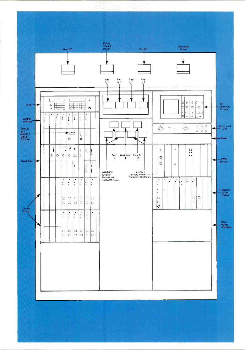
Main HT
Output Forward Power V.S.W.R
Conttol Modules
Standby and Main H T
On :ff Control
Pen Pen Final Final Ig 1 Ig 2 Ig 1 Ig 2
Backward Power
"4-- -__ o J-
00 0 O
0 O
O
0 O
0 O . . . . O ro
0 0 0 0 0 0 A A A
t gSB. t =
Wideband Amplifier Forward Backward
Pen Ik
and Power
Modulator Ik
Final Ik
yr
Forward Reflection
RF
Circui Power Coefficient
and
O . .
D
O
O
O
O
D
D
O
O
O
O
D
O D
O O
O O
D O D O
O O
4
4
4
R.F Envelope Monitor
Audio Input Unit
Blank
PWM Encoder
Frequency Follow Tuning
Servo Power Amplifiers

energy in the capacitors and reactors causes a damped oscillation around the filter and modulation components unless special precautions are taken to avoid this situation.
If required, a 12 pulse rectifier system may be used to limit the harmonic currents introduced into the mains supply system.
Power Supplies Two mains supplies are required for the transmitter: one three phase, four wire low voltage supply at 380 or 415V for auxiliaries, bias and low lower H.T supplies; the other a high voltage three phase, three wire supply for the main H.T rectifier.
The transmitter d.c power supplies are mounted in the main cubicle with the exception of the main H.T which is in the rear enclosure.
Reduction of R.F output to approximately half and quarter power is provided by low level control of the H.T. This can be carried out manually by front panel control or automatically.
All rectifiers employ silicon diodes tested to withstand direct short circuits.
Control and Monitoring All control and monitoring functions required for normal operation of the transmitter are grouped together on the front panel. From here the full start up and close down sequence can be controlled by single button control during normal operation. The full tuning sequence when selecting new frequencies is also initiated at the control panel area, and a full set of status and fault diagnosis indicators are provided. An oscilloscope enables the R.F and audio waveforms to be observed and can be used in setting modulation levels.
Operational controls, together with status and fault diagnosis indicators, can be repeated remotely.
The centre passageway through the transmitter provides access to controls, interlocks and pressure gauges for the water cooling system and the pneumatic system for the R.F switches. It also provides access to the H.T enclosure when positioned to the rear of the transmitter.
Although a failure of the incoming a.c supply will cause the transmitter to close down, if the period of failure does not exceed fifteen seconds the transmitter will re -start immediately upon the reapplication of power, without going through the normal starting delays.
Pneumatic System Maintenance requirements have received a high priority in the design of this transmitter. The twin cabinet arrangement provides exceptionally good accessibility. Moreover, in the R.F cabinet there is a rigid division down the centre between the R.F circuits and their ancillaries. Thus all motor drives for capacitor tuning, switch actuators, and the water cooling system are positioned in very accessible positions to facilitate
routine checks and maintenance. Tube changing is rapid because
of the low temperature of the components and the quick release self sealing hose connections.
All the low level solid state equipment is grouped in the modulator cabinet with easy access.
Major diagnostic aids are provided on the front panel. The control unit includes an array of I.e.d's providing a full set of status and overload indications.
The low level units are mounted on telescopic runners for easy access.
Modular type construction is used in the logic and control circuitry, permitting easy replacement or exchange of logic boards. In many instances logic boards are common, thus economising in spares holding.
Cooling It is common experience to those who operate high power high frequency transmitters that many of the problems encountered can be traced back to overheating, especially those concerned with high power R.F contacts. This problem becomes even more severe in automatic frequency changing systems employing moving contacts, and even more so at high power levels and when circuit currents become large. This particularly applies to continuously variable inductors.
Such high power inductors are, therefore, avoided in the B6126 where range changing is accomplished by well proven pneumatically operated R.F switches with water cooled contacts, and fine tuning by water cooled variable vacuum capacitors. The two high power vacuum tubes operate on the 'hypervapotron' principle and the remaining tube is conventionally water cooled. The cooling system employed contributes directly to the reduction of 'down -time' for maintenance or tube changing, since the transmitter parts are cool to the touch and such measures as the use of special gloves for handling hot components are not required.
Distilled or demineralised water is used as a coolant and is pumped in a closed water circuit which includes a reservoir tank and an external heat exchanger. Normally the heat exchanger is air blast cooled. Alternatively, a water cooled heat exchanger may be more suitable. Both the type of heat exchanger, and its position in relation to the transmitter, can be chosen to suit the site conditions.
The air cooling system delivers high pressure air to cool the seals of the modulator, penultimate R.F and final R.F tubes. In addition, both the main transmitter cubicles and the H.T enclosure are cooled by low pressure air. An external air filter is supplied; this may be a roll type filter (if this is demanded by the environmental conditions) or alternative filters of a suitable type. The air cooling systems are protected by pressure switches and thermal overloads and a 'hold on' circuit ensures adequate
cooling after shut down for a few minutes.
Protection The transmitter embodies comprehensive protection circuits whose operation is initiated by sensors which monitor overcurrent, overvoltage, high v.s.w.r or malfunctioning of the cooling system. A three shot recycling overload system is incorporated.
While great improvements have been made in reducing the hazard of internal flash -arcs in high power vacuum tubes, the manufacturers nevertheless specify a protection requirement should a flash -arc occur. These requirements are more than adequately met by the 86126. In the final R.F amplifier or modulator an incipient flash -arc triggers the 'crowbar' and also opens the six vacuum switches between the H.T transformer and rectifier bridge.
Arc detectors are strategically positioned to detect any arcing occurring in the R.F power circuits.
Safety To ensure the safety of all
personnel, a system of mechanical and electrical interlocks is used. With the main isolator open, access to all parts of the transmitter is available with complete safety. When closed, filaments, fans and control circuits can be powered with certain doors open.
However, where voltage over 50V a.c are applied, covers and warning notices are fitted. Before high voltages can be applied, all doors have to be locked and the keys returned to an interlock panel. When all keys are located the earth switch and power switch can be operated, allowing power to be switched on. While power is
on it is impossible for a key to be released.
Earthing is provided for the R.F feeder and for high voltage supplies.
The equipment conforms generally to IEC215.
The outgoing R.F feeder is isolated by a feeder earthing and isolator switch.
Construction For ease of installation and transport the transmitter is built up from two cubicles, each of which dismantle into two sections which can be conveniently handled. Each of the four sections is built on a robust steel base.
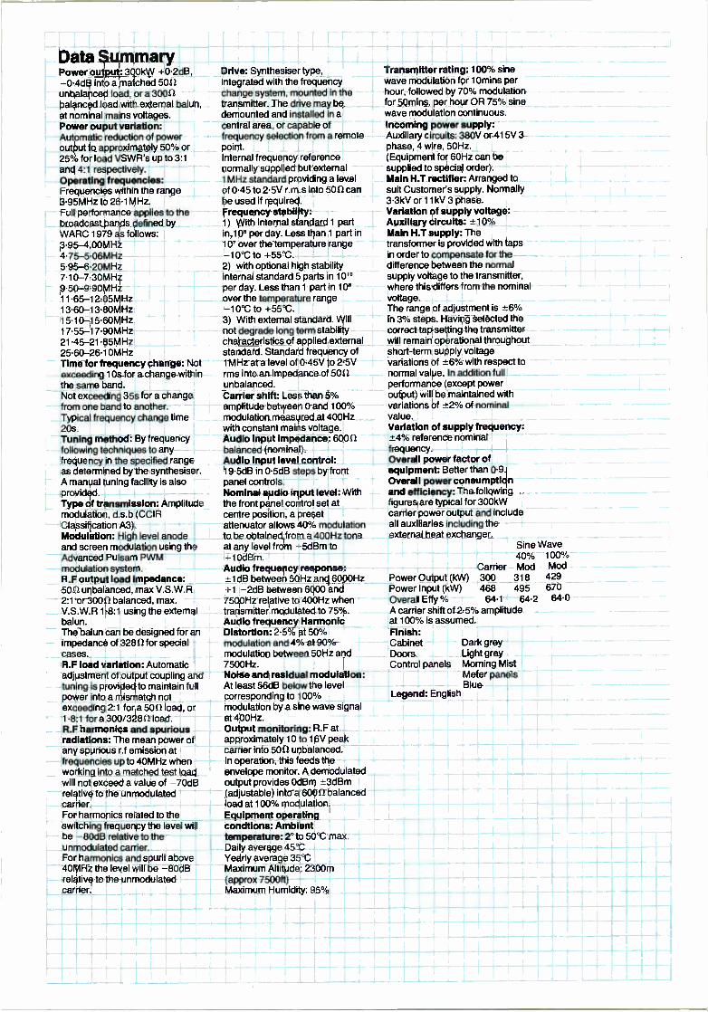
Data Summary Power output: 300kW +0.2dB, -0.4dB into a matched 50U unbalanced load, or a 30012 balanced load with external balun, at nominal mains voltages. Power ouput variation: Automatic reduction of power output to approximately 50% or 25% for load VSWR's up to 3:1
and 4:1 respectively. Operating frequencies: Frequencies within the range 3.95MHz to 26.1 MHz. Full performance applies to the broadcast bands defined by WARC 1979 as follows: 3.95- 4.00MHz 4.75- 5.06MHz 5.95 -6 20MHz 7.10- 7.30MHz 9.50- 9.90MHz 11.65- 12.05MHz 13.60- 13.80MHz 15.10- 15.60MHz 17.55- 17.90MHz 21.45- 21.85MHz 25.60- 26.10MHz Time for frequency change: Not exceeding t Os for a change within the same band. Not exceeding 35s for a change from one band to another. Typical frequency change time 20s. Tuning method: By frequency following techniques to any frequency in the specified range as de'ermined by the synthesiser. A manual tuning facility is also provided. Type of transmission: Amplitude modulation, d.s.b (CCIR Classification A3). Modulation: High level anode and screen modulation using the Advanced Pulsam PWM modulation system. R.F output load impedance: 5012 unbalanced, max V.S.W.R 2:1 or 3001 2 balanced, max. V.S.W.R 1.8:1 using the external balun. The balun can be designed for an impedance of 32812 for special cases. R.F load variation: Automatic adjustment of output coupling and tuning is provided to maintain full power into a mismatch not exceeding 2:1 for a 50121oad, or 1.8:1 for a 300/32812 load. R.F harmonics and spurious radiations: The mean power o any spurious r.f emission at frequencies up to 40MHz when working into a matched test load will not exceed a value of 70dB relative to the unmodulated carrier. For harmonics related to the switching frequency the level w'II be -80dB relative to the unmodulated carrier. For harmonics and spurii above 40MHz the level will be -80dB relative to the unmodulated carrier.
Drive: Synthesiser type, integrated with the frequency change system, mounted in the transmitter. The drive may be demounted and installed in a central area, or capable of frequency selection from a remote point. Internal frequency reference normally supplied but external 1 MHz standard providing a level of 0.45 to 2.5V r.m.s into 5012 can be used if required. Frequency stability: 1) With internal standard 1 part in,10° per day. Less than 1 part in
10' over the temperature range -10 °C to +55°C. 2) with optional high stability internal standard 5 parts in 10'° per day. Less than 1 part in 10° over the temperature range -10 °C to +55 °C.
3) With external standard. Will not degrade long term stability characteristics of applied external standard. Standard frequency of 1MHz at a level of 0.45V to 2.5V rms into an impedance of 5012 unbalanced. Carrier shift: Less than 5% amplitude between 0 and 100 °ró
modulation measured at 400Hz with constant mains voltage. Audio input impedance: 60012 balanced (nominal). Audio input level control: 19.5dB in 0.5dB steps by front panel controls. Nominal audio input level: With the front panel control set at centre position, a preset attenuator allows 40% modulation to be obtained from a 400Hz tone at any level from -5dBm to -10dBm. Audio frequency response: -1 dB between 50Hz and 6000Hz
1 -2dB between 6000 and 7500Hz relative to 400Hz when transmitter modulated to 75 %. Audio frequency Harmonic Distortion: 2.5% at 50% modulation and 4% at 90% modulation between 50Hz and 7500Hz. Noise and residual modulation: At least 56dB below the level corresponding to 100% modulation by a sine wave signal at 400Hz. Output monitoring: R.F at approximately 10 to 16V peak carrier into 5012 unbalanced. In operation, this feeds the envelope monitor. A demodulated output provides OdBm -3dBm (adjustable) into a 60012 balanced load at 100% modulation. Equipment operating condtions: Ambient temperature: 2° to 50°C max. Daily average 45°C Yearly average 35°C Maximum Altitude: 2300m (approx 7500ft) Maximum Humidity: 95%
Transmitter rating: 100% sine wave modulation for 10mins per hour, followed by 70% modulation for 50mins. per hour OR 75% sine wave modulation continuous. Incoming power supply: Auxiliary circuits: 380V or 415V 3 phase, 4 wire, 50Hz. (Equipment for 60Hz can be supplied to special order). Main H.T rectifier: Arranged to suit Customer's supply. Normally 3.3kV or 11 kV 3 phase. Variation of supply voltage: Auxiliary circuits: -±10% Main H.T supply: The transformer is provided with taps in order to compensate for the difference between the normal supply voltage to the transmitter, where this differs from the nominal voltage. The range of adjustment is +6% in 3% steps. Having selected the correct tap setting the transmitter will remain operational throughout short-term supply voltage variations of +6% with respect to normal value. In addition full performance (except power output) will be maintained with variations of ±2% of nominal value. Variation of supply frequency: -4% reference nominal frequency. Overall power factor of equipment: Better than 0.9. Overall power consumption and efficiency: The following figures are typical for 300kW carrier power output and include all auxiliaries including the external heat exchanger.
Sine Wave 40%
Carrier Mod 100 °r Mod
Power Output (kW) 300 318 429 Power Input (kW) 468 495 670 Overall Effy % 64.1 64.2 64.0 A carrier shift of 2.5% amplitude at 100% is assumed. Finish: Cabinet Doors Control panels
Dark grey Light grey Morning Mist Meter panels Blue
Legend: English

Marconi Communication Systems Broadcasting Division New Street Chelmsford, England CM1 1PL Telephone 0245 353221 Telex 99201 Facsimile 0245 87125 Group 3
1 9 8 1 TD-B6126
This document gives only a general description of the product(s) and shall not form part of any contract. ©1984 The Marconi Company Limited From time to time changes may be made in the products or in the conditions of supply. Printed in England by Lund Humphries 1 8 0 9 84 /3000