mapk-602 conductivity/ salinity meter - csvg.cz · mapk-602 conductivity/salinity meter. ......
TRANSCRIPT

MAPK-602
CONDUCTIVITY/ SALINITY METER Operation Manual Nizhny Novgorod 2010
АЯ74

2
VZOR Ltd. will be grateful for any proposals and criticisms helping improve the product.
If you have any trouble using the instrument please contact us in writing or by phone.
Postal address: 603106, Russia, Nizhny Novgorod, POB 253 Telephone: + 7 (831) 229-65-67, 412-29-40 E-mail: [email protected] Website: www.vzornn.com

3
C O N T E N T S
1 DESCRIPTION AND OPERATION ....................................................................... 4 1.1 Purpose ............................................................................................................ 4 1.2 Basic parameters ............................................................................................. 5 1.3 Specifications of each measuring channel ...................................................... 7 1.4 Product components ........................................................................................ 9 1.5 Design and operation ....................................................................................... 9
2 INTENDED USE .................................................................................................. 26 2.1 Operating limitations ...................................................................................... 26 2.2 Safety precautions ......................................................................................... 26 2.3 Conductivity meter setting-up procedures ..................................................... 27 2.4 Measurements ............................................................................................... 34 2.5 Troubleshooting ............................................................................................. 34 2.6 Supply line fuses ............................................................................................ 36
3 MAINTENANCE ................................................................................................... 37 3.1 Washing of conductivity probes and heat sensor .......................................... 37 3.2 Converting unit maintenance ......................................................................... 37 3.3 Checking the conductivity meter and adjusting the probe constant .............. 37
4 DELIVERY SET ................................................................................................... 43
4
1 DESCRIPTION AND OPERATION 1.1 Purpose
1.1.1 Product name and identification
A panel-mounted conductivity meter with CP-025С and CP-2С flow-type conductivity probes.
MAPK-602 conductivity/salinity meter. TU 4215-025-39232169-2006 Specifications. A wall-mounted conductivity meter with CP-025С and CP-2С flow-type con-
ductivity probes. MAPK-602/1 conductivity/salinity meter. TU 4215-025-39232169-2006 Specifications. A panel-mounted conductivity meter with CP-003LD main/immersion con-
ductivity probes. MAPK-602LD conductivity/salinity meter. TU 4215-025-39232169-2006 Specifications. A wall-mounted conductivity meter with CP-003LD main/immersion conduc-
tivity probes. MAPK-602LD/1 conductivity/salinity meter. TU 4215-025-39232169-2006 Specifications. 1.1.2 Purpose The MAPK-602 conductivity meter is designed to measure electric conductiv-
ity and electric conductivity (SEC) referred to 25 °С, and to calculate equivalent sa-linity referred to sodium chloride (NaCl) of water and aqueous solutions.
1.1.3 Applications heat power engineering, pharmaceutical industry, fish farming and production processes.
1.1.4 Conductivity meter types: contact; low frequency; with passive sensors − CP-025С and CP-2С flow-type conductivity probes
or CP-003LD line-dip conductivity probes; quick-response; with two measuring channels; with automatic temperature compensation; as a panel- or wall-mounted unit; measurement readouts via the current output and RS-485 port.

5
1.2 Basic parameters
1.2.1 By resistance to climatic effects this conductivity meter version falls within B4 group as per GOST 12997-84.
1.2.2 By resistance to mechanical action the conductivity meter version falls within L1 group as per GOST 12997-84.
1.2.3 By protection against environmental exposure the conductivity meter components, depending on the version, are made to GOST 14254-96, in accord-ance with Table 1.1. Table1.1 Conductivity meter
version Component name and identification Component version
as per GOST 14254 MAPK-602, MAPK-602LD
Converting unit ВР30.01.000(panel-mounted version)
IP30
MAPK-602/1, MAPK-602LD/1
Converting unit ВР42.01.000 (wall-mounted version)
IP65
MAPK-602, MAPK-602/1
CP-025С conductivity probe ВР30.02.000
IP62
CP-2C conductivity probe ВР30.02.000-01
IP62
MAPK-602LD, MAPK-602LD/1
CP-003LD conductivity probe ВР30.10.000 (immersible section)
IP68
1.2.4 By resistance to atmospheric pressure the conductivity meter version
falls within Р1 group as per GOST 12997-84 (atmospheric pressure from 84 to 106.7 kPa).
1.2.5 Analyte medium parameters 1.2.5.1 Analyte medium temperature range, C ...…………………. +5 to +50. 1.2.5.2 Analyte medium pressure, MPa, max: for MAPK-602 and MAPK-602/1 versions ………..………..…..….…….. 0.1; for MAPK-602LD and MAPK-602LD/1 versions ……...………....…….….. 1. 1.2.5.3 Aqueous solution flow rate for MAPK-602 and MAPK-602/1 versions,
dm3/h ...……………..……..…………..………………………………………….. 3 to 30. 1.2.5.4 Analyte medium velocity perpendicular to the probe axis for
MAPK-602LD and MAPK-602LD/1 versions, cm/s, min ………………………….... 5. 1.2.6 Operating conditions 1.2.6.1 Ambient air temperature, C …………………………………. +5 to +50. 1.2.6.2 Ambient air relative humidity at +35С and below without moisture
condensation, %, max ......................................................................................… 80. 1.2.6.3 Atmospheric pressure, kPa (mm of Hg) .... 84.0 to 106.7 (630 to 800). 1.2.6.4 The conductivity meter is powered from single-phase 220 V AC
(50 ± 1) Hz mains. The supply voltage tolerance varies from –15 to +10 %. 1.2.7 Power consumption at the rated supply voltage, VA, max ……..…... 10.

6
1.2.8 Overall dimensions and weight of the conductivity meter components are as shown in Table 1.2 below. Table 1.2
Conductivity meter version
Component name and identification
Overall dimensions, mm, max
Weight, kg, max
MAPK-602, MAPK-602LD
Converting unit ВР30.01.000 252146100 2.60
MAPK-602/1, MAPK-602LD/1
Converting unit ВР42.01.000 26617095 2.60
MAPK-602LD, MAPK-602LD/1
CP-025С conductivity probe ВР30.02.000 11514530 0.27
CP-2С conductivity probe ВР30.02.000-01 11514530 0.27
CP-003LD conductivity probe ВР30.10.000 54130 0.50
1.2.9 The conductivity meter must be transported in shipping crates as per
GOST 12997-84. 1.2.9.1 Temperature, С .……………………….............................. –20 to +50. 1.2.9.2 Relative humidity at 35 С, % ….……...……………………..…....... 95. 1.2.9.3 Sinusoidal vibration with a frequency of 5-35 Hz, shift amplitude of
0.35 mm in the direction shown by the "THIS END UP" mark on the crate. 1.2.10 Reliability requirements 1.2.10.1 Mean time to failure, h, min ……..……….………….…....…... 20.000. 1.2.10.2 Mean time to fix, h, max ..…………………………………………..… 2. 1.2.10.3 Conductivity meter’s mean life, years, min …………………...…... 10. 1.2.11 Resistance of electrical insulation of the conductivity meter’s supply
circuits between plug pins and case, M, min: at ambient temperature of (20 ± 5) С ……………………………………. 40; at ambient temperature of 50 С ……………….....………………………. 10; at ambient temperature of 35 С and relative humidity of 80 % ...………. 5. 1.2.12 Electrical insulation of the conductivity meter’s supply circuits relative
to the converting unit case handles a 1-minute 1.5 kV testing voltage of sinusoidal AC 50 Hz at an ambient temperature of (20 ± 5) С relative humidity from 30 to 80 %.
1.2.13 Electrical insulation between the external terminal of the converting unit earthing and its case, , max ……………………………..………………….... 0.1.

7
1.3 Specifications of each measuring channel 1.3.1 SEC and salinity measuring ranges are listed in Table 1.3.
Table 1.3 Conductivity meter
version Conductivity
probe Measuring range
SEC, μSm/cm
salinity in sodium chloride equivalent, ppm
MAPK-602, MAPK-602/1
CP-025С 0 to 2000 0 to 1.000 CP-2С 0 to 20.000 0 to 10.000
MAPK-602LD, MAPK-602LD/1 CP-003LD 0 to 200 0 to 100
1.3.2 The conductivity meter’s margin of allowable basic absolute measuring error at an analyte medium temperature of (25.0 ± 0.2) С and ambient air temper-ature of (20 ± 5) С is as shown in Table 1.4 below. Table 1.4
Conductivity meter
version
Conductivity probe
Conductivity meter’s margin of allowable basic absolute measuring
error SEC,
μSm/cm salinity,
ppm MAPK-602, MAPK-602/1
CP-025С ± (0.004 + 0.02χ) ± (0.003 + 0.025С) CP-2С ± (0.03 + 0.02χ) ± (0.03 + 0.025С)
MAPK-602LD, MAPK-602LD/1
CP-003LD ± (0.001 + 0.02χ) ± (0.001 + 0.025С)
Note: χ measured SEC value, μSm/cm; С measured salinity value, ppm
1.3.3 The conductivity meter’s margin of allowable basic absolute measuring error caused by analyte medium temperature variations within a temperature com-pensation range from +5 to +50С:
SEC measurement, μSm/cm …………...…………………………….... 0.02χ; salinity measurement, ppm ………………...………………..……….. 0.025С. 1.3.4 The conductivity meter’s margin of allowable basic absolute measuring
error, resulting from ambient temperature deviation from normal temperature (20 ± 5) С per each ± 10 С within an operating temperature range from +5 to +50 С:
SEC measurement, μSm/cm …...………………………...….………… 0.01χ; salinity measurement, ppm ..…………………….………...…….…… 0.012С. 1.3.5 The conductivity meter’s margin of allowable basic absolute measuring
error resulting from the effect by the “conductivity probe – converting unit” connect-or length with a connecting cable length of up to 100 m:
SEC measurement, μSm/cm ....…………………..……………….…. 0.016χ; salinity measurement, ppm ………………………………………….…. 0.02С.
8
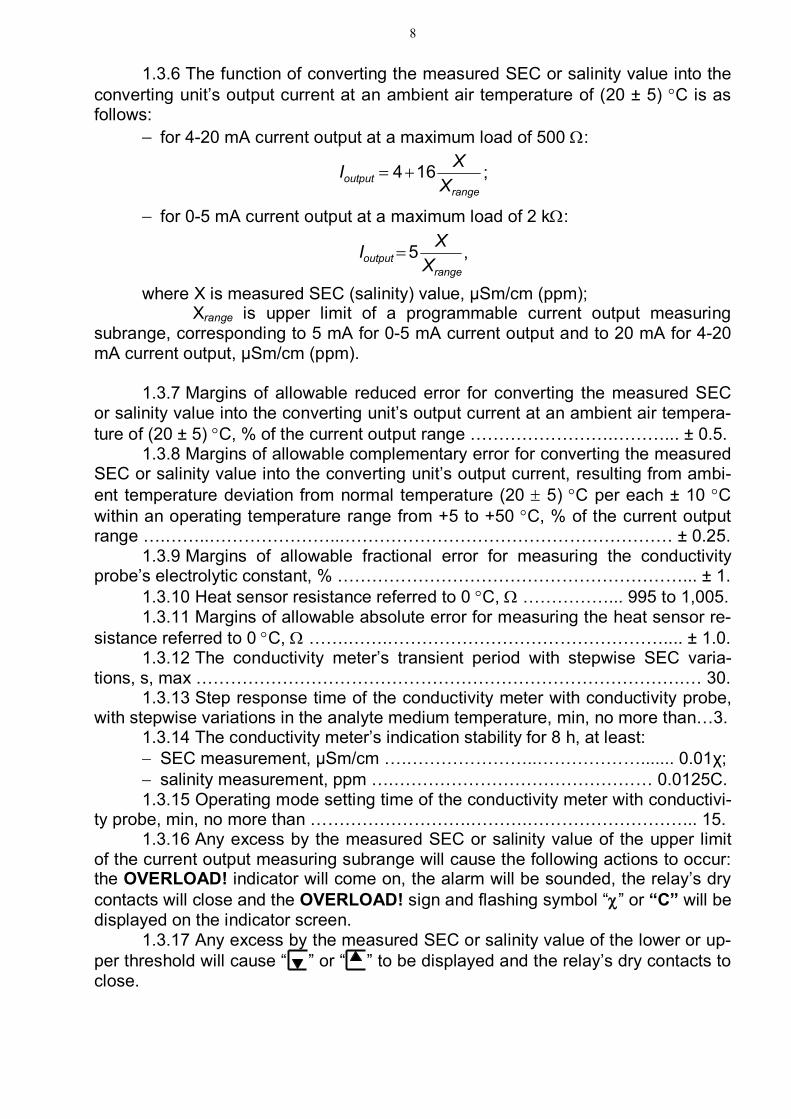
1.3.6 The function of converting the measured SEC or salinity value into the converting unit’s output current at an ambient air temperature of (20 ± 5) С is as follows:
for 4-20 mА current output at a maximum load of 500 :
rangeoutput X
XI 164 ;
for 0-5 mА current output at a maximum load of 2 k:
rangeoutput X
XI 5 ,
where X is measured SEC (salinity) value, μSm/cm (ppm); Xrange is upper limit of a programmable current output measuring
subrange, corresponding to 5 mА for 0-5 mА current output and to 20 mА for 4-20 mА current output, μSm/cm (ppm).
1.3.7 Margins of allowable reduced error for converting the measured SEC
or salinity value into the converting unit’s output current at an ambient air tempera-ture of (20 ± 5) С, % of the current output range …………………….………... ± 0.5.
1.3.8 Margins of allowable complementary error for converting the measured SEC or salinity value into the converting unit’s output current, resulting from ambi-ent temperature deviation from normal temperature (20 5) С per each ± 10 С within an operating temperature range from +5 to +50 С, % of the current output range ….……..…………………...………………………………………………… ± 0.25.
1.3.9 Margins of allowable fractional error for measuring the conductivity probe’s electrolytic constant, % ……………………………………………………... ± 1.
1.3.10 Heat sensor resistance referred to 0 С, ……………... 995 to 1,005. 1.3.11 Margins of allowable absolute error for measuring the heat sensor re-
sistance referred to 0 С, …….…….………………………………………….... ± 1.0. 1.3.12 The conductivity meter’s transient period with stepwise SEC varia-
tions, s, max ………………………………………………………………………….… 30. 1.3.13 Step response time of the conductivity meter with conductivity probe,
with stepwise variations in the analyte medium temperature, min, no more than…3. 1.3.14 The conductivity meter’s indication stability for 8 h, at least: SEC measurement, μSm/cm ….…………………..………………....... 0.01χ; salinity measurement, ppm ….……………………………………… 0.0125С. 1.3.15 Operating mode setting time of the conductivity meter with conductivi-
ty probe, min, no more than ……………………….……….………………………... 15. 1.3.16 Any excess by the measured SEC or salinity value of the upper limit
of the current output measuring subrange will cause the following actions to occur: the OVERLOAD! indicator will come on, the alarm will be sounded, the relay’s dry contacts will close and the OVERLOAD! sign and flashing symbol “” or “С” will be displayed on the indicator screen.
1.3.17 Any excess by the measured SEC or salinity value of the lower or up-per threshold will cause “ ” or “ ” to be displayed and the relay’s dry contacts to close.

9
1.3.18 Analyte medium temperatures below 0 С and above 50 С enable the OVERLOAD! indicator and alarm and cause the relay’s dry contacts to close and the OVERLOAD! sign and flashing symbol “С” to be displayed.
1.3.19 When connected to a personal computer (PC), the conductivity meter exchanges information with PC via the RS-485 interface.
1.4 Product components
The conductivity meter is comprised of the following components: panel-mounted (for MAPK-602 and MAPK-602LD versions) or wall-
mounted (for MAPK-602/1 and MAPK-602LD/1 versions) converting unit; CP-025С conductivity probe and/or CP-2С conductivity probe (for
MAPK-602 and MAPK-602/1 versions); CP-003LD conductivity probe (for MAPK-602LD and MAPK-602LD/1 ver-
sions); connecting cables; mounting parts kit; tool and accessory kit.
1.5 Design and operation 1.5.1 Conductivity meter general data
The conductivity meter is a dual-channel measuring instrument designed for continuous measuring of SEC or SEC equivalent salinity referred to sodium chlo-ride (NaCl) via two measuring channels A and B.
The measured SEC or equivalent analyte medium salinity value is displayed on a readout device − a digital LCD display (“the display”). It provides separate or simultaneous indication of parameters measured in channels A and B.
Each channel has a dedicated programmable subrange for current output measurement.
The lower limit of the programmable subrange for current output measure-ment is always 0 μSm/cm (0 ppm).
The upper limit may be set within a range from 0.1 μSm/cm (0.1 ppm) to the upper measuring range limit, depending on the connected type of probe. The pre-set upper limit of current output measurement is shown on the display.

10
The conductivity meter has two outputs with unified output DC signals from 0 to 5 mА or from 4 to 20 mА, corresponding to the two SEC or salinity measuring channels. The upper limit of the programmable subrange for current output meas-urement corresponds to a current of 5 or 20 mА. The required current output range (from 0 to 5 mА or from 4 to 20 mА) is chosen by the user separately for each channel through an option on the conductivity meter menu.
In addition to unified output DC signals from 0 to 5 mА or from 4 to 20 mА, the conductivity meter menu enables unified output signals from 0 to 20 mА to be set in each of the channels.
Independent of the set current output subrange, the conductivity meter dis-play’s measuring range is only determined by the type of probe employed. For SEC (salinity) measurement beyond the set measuring range the measuring error is not normalized.
SEC measuring range using: CP-025С conductivity probe − 0 to 2,000 μSm/cm; CP-2С conductivity probe − 0 to 20,000 μSm/cm; CP-003LD conductivity probe − 0 to 200 μSm/cm. Salinity measuring range using: CP-025С conductivity probe − 0 to 1,000 ppm; CP-2С conductivity probe − 0 to 10,000 ppm; CP-003LD conductivity probe − 0 to 100 ppm. The above instruments are contact-type conductivity probes with built-in heat
sensors. They are passive devices (without electronic elements) and may be taken up to 100 m away from a converting unit.
The probe’s constant value СP, cm-1, is shown in Table 3.1 of this Manual. A heat sensor (thermoresistor) resistance value referred to 0 С, Rt, , is shown in Para. 5.
Values Сp, cm-1, and Rt, , characterizing each particular conductivity probe must be entered (when using this probe) into the converting unit memory to allow sensor interchangeability. Values СP, cm-1, and Rt, , are entered in the parameter
monitoring and changing mode enabled by pressing the entermenu button on the face
panel and used to set all the conductivity meter’s operating modes and parame-ters.
For easier SEC monitoring, provision is made in the conductivity meter for temperature compensation, i.e. reference of the SEC absolute value to SEC at 25 С. Having a double algorithm, temperature compensation is provided for the absolutely clean water SEC component and for the component depending on the agents dissolved in water (temperature dependence approximated by a linear law – the so-called linear temperature compensation).
The linear temperature compensation factor depending on the composition of agents dissolved in water may be set by the user within a range from 0.0140 to 0.0200 degrees-1.
The conductivity meter has a measuring mode for SEC not referred to 25 С (with temperature compensation disabled).

11
Any excess by the measured SEC or salinity value of the upper limit of the current output measuring subrange will cause the OVERLOAD! indicator to come on, the OVERLOAD! sign and the flashing symbol of an overloaded parameter (“” or “С”) to be displayed and the relay’s dry contacts to close.
If the analyte medium temperature goes beyond the range from 0 to +50 С, the OVERLOAD! indicator will come on, the alarm will be sounded and the relay’s dry contacts will close. Also, the OVERLOAD! sign and the flashing symbol “C” will be displayed.
Each of the conductivity meter’s channels has two freely programmable thresholds setting the upper and lower monitoring limits for an SEC or salinity value being measured. If SEC or salinity values exceed the threshold limits, the relay’s dry contacts close and a sign of the upper or lower threshold limit is displayed (“ ” or “ ”).
The tool and accessory kit of MAPK-602LD (MAPK-602LD/1) conductivity meter includes a flow-through cell for flow-through measurements or a housing to install the probe in a main pipeline, supplied as agreed upon with the customer.
1.5.2 Conductivity meter’s operating principle 1.5.2.1 SEC measuring principle SEC measurement involves supply of constant AC voltage to a conductivity
probe and measurement of current flowing through the probe. The current value, including the probe’s electrolytic constant CP, is transferred to the controlled medi-um SEC. To define SEC referred to 25 °С, use is made of the measured tempera-ture value.
1.5.2.2 Temperature measuring principle Temperature readings are determined by transferring the heat sensor’s
measured resistance value. Such transfer using the heat sensor’s resistance value referred to 0 С, Rt, .

12
1.5.2.3 SEC temperature compensation principle (referring the measured SEC to 25 °С)
Temperature compensation comprises the following two stages: “pure” water SEC temperature compensation; salt solution temperature compensation. 1.5.2.4 Salinity measuring principle Salinity is defined by transferring a temperature-compensated (referred to
25 °С) solution SEC to NaCl salt concentration using the known dependence. 1.5.3 Conductivity meter’s components
1.5.3.1 Converting unit
The converting unit (CU) is designed to convert conductivity probe signals, display measuring data, generate a signal at current outputs, control the relay’s dry contacts and data communication to PC.
CU is powered from 220 V DC 50 Hz mains through the built-in power sup-ply.
The CU front panel features the following components (Fig.1.1): display screen designed to indicate measured or referred SEC values and
temperatures, conductivity meter modes, and to work with screen menus; button “ “ to switch on and off the display screen illumination; “” and “” buttons to move down and up the menu in the parameter
monitoring and changing mode and to change the settings; “CHANNEL” button to change the indication mode (channel A, channel B
or both channels) and perform some operations in the MENU mode;
“entermenu ” button to enter the menu (invoke the parameter monitoring and
changing mode) and confirm the values and operating modes selected in pro-gramming;
“POWER” button to switch the conductivity meter on and off; “POWER” green light power on indicator;

13
“OVERLOAD” red light indicator to show an overloaded programmable range for current output measurement or analyte medium temperature exceeding the range from 0 to +50 С.
Figure 1.1 − Layout of controls and indicators on the converting unit face panel
The panel-mounted CU rear panel (see Fig.1.2) and the wall-mounted CU
lower panel (see Fig.1.3) feature the following components: two connectors “CHANNEL А” and “CHANNEL B” to hook up conductivity
probes to the converting unit; “CURRENT OUTPUT, SIGNALING, RS-485” connector to hook up re-
cording and actuating equipment and to hook up the conductivity meter to PC; terminal “ ” to connect protective earthing to the conductivity meter
frame. The panel-mounted CU rear panel features the “~220 V 50 Hz 10 V∙A
1.0 A” mains connector. The wall-mounted converting unit lower panel features the “~220 V 50 Hz
10 V∙A 1.0 A” sealed mains cable entry.
Conductivity meter
MAPK 602
CHANNEL
ALARM POWER 1 0
MENU
ENTER

14
Figure 1.2 − Layout of connectors on the panel-mounted converting unit rear panel
Figure 1.3 − Layout of connectors the wall-mounted converting unit lower panel
~220 V 50 Hz 10 V∙A 1.0 A
CURRENT OUTPUT
SIGNALING RS-485
CHANNEL В CHANNEL А
CHANNEL В CHANNEL А CURRENT OUTPUT
SIGNALING
RS-485
~220 V 50 Hz 10 V∙A 1.0 A

15
1.5.3.2 Conductivity probes CP-025С and CP-2С are flow-type conductivity probes with electrodes of
stainless steel. The CP-025С (CP-2С) conductivity probe is shown in Fig.1.4. The probes have a sealed aluminum housing that accommodates electrode
assembly 1, heat sensor 2 based on platinum thermoresistor with connector 3, connector 4 for shielded connecting cable, and two metal pipe connections − inlet connection 5 for supply of controllable solution and outlet connection 6. The con-ductivity probe is secured to the vertical surface with М48 screws using holes 7. Conductivity probe cover 8 providing a sealed enclosure for the probe electrode section is secured with screws 9.
Figure 1.4 CP-025С (CP-2С) conductivity probe
CP-003LD is a line-dip conductivity probe with electrodes of stainless steel. The CP-003LD conductivity probe is shown in Fig.1.5.
1 2
3 6
4 5
9
8
7
115
65
102
35
TOP
108
8

16
Figure 1.5 CP-003LD conductivity probe
The conductivity probe electrode section consists of case 1 and inside elec-trode 2 fitted with a heat sensor based on platinum thermoresistor. Connector 3 is intended for shielded connecting cable. The probe has M332 thread.
For flow-through measurements the conductivity probe is set in flow-through cell 4.
The flow-through cell has two nipples (ball-cone) − inlet 5 and outlet 6, with a pipe connection outside diameter of 9 mm. The flow-through cell is connected to the process pipeline with a metal pipe (by welding).
Designed to install the conductivity probe for main pipeline measurements, housing 7 is welded into the pipeline.
10
38
40
40
7
134
6
40 4
5
3
2
1
M332
24
□ 36 64
134
84
17
The flow-through cell and housing are included in the tool and accessory kit and supplied as agreed upon with the customer.
1.5.4 Measuring screens
1.5.4.1 Types of measuring mode screens
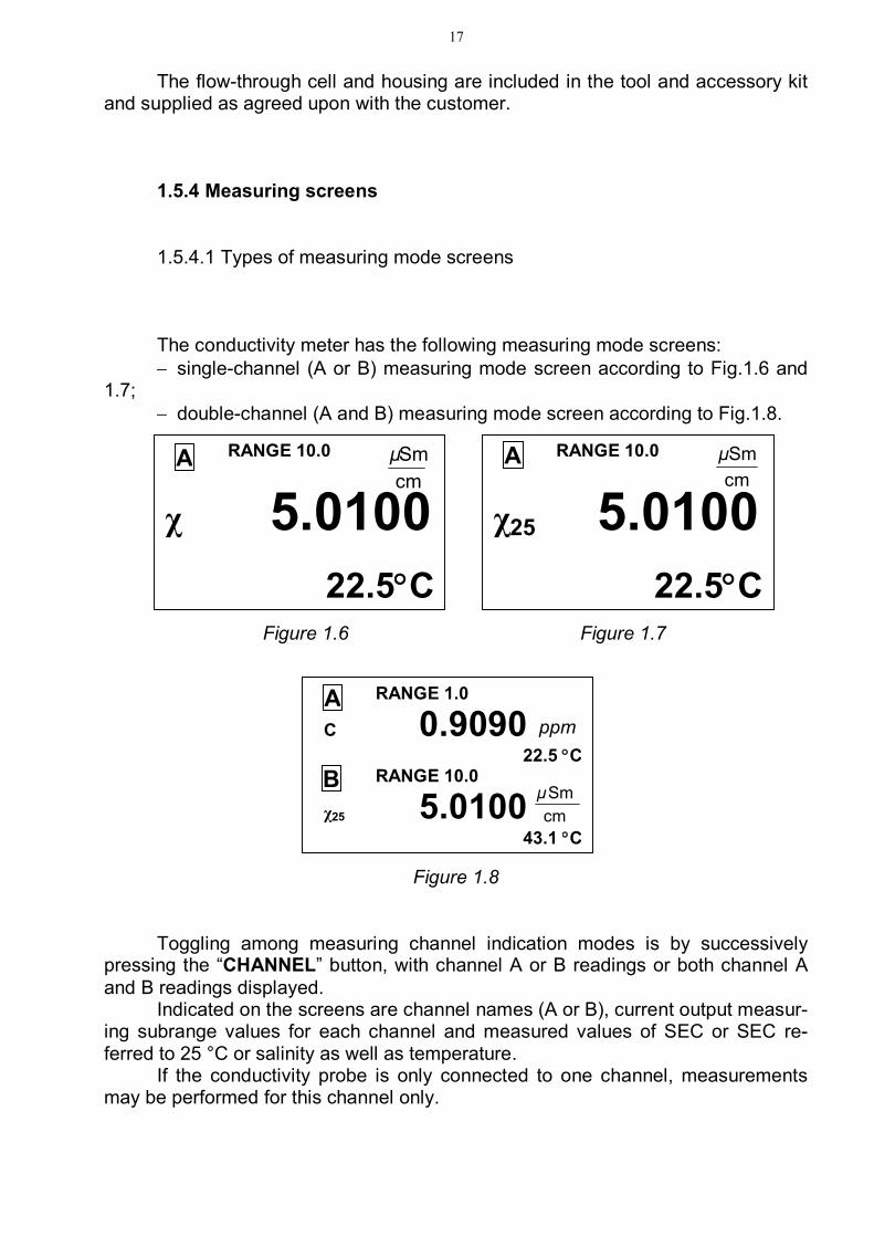
The conductivity meter has the following measuring mode screens: single-channel (А or В) measuring mode screen according to Fig.1.6 and
1.7; double-channel (А and В) measuring mode screen according to Fig.1.8.
Figure 1.6 Figure 1.7
Figure 1.8
Toggling among measuring channel indication modes is by successively pressing the “CHANNEL” button, with channel A or B readings or both channel A and B readings displayed.
Indicated on the screens are channel names (А or В), current output measur-ing subrange values for each channel and measured values of SEC or SEC re-ferred to 25 °С or salinity as well as temperature.
If the conductivity probe is only connected to one channel, measurements may be performed for this channel only.
RANGE 10.0
χ 5.0100
22.5С
А cmSmμ
RANGE 10.0
χ25 5.0100
22.5С
А cmSmμ
RANGE 1.0
С 0.9090 22.5 С
RANGE 10.0
χ25 5.0100 43.1 С
А ppm
В cmSmμ

18
1.5.5 Types of setting monitoring and changing mode screens (MENU mode)
1.5.5.1 General information on handling the MENU
The conductivity meter’s parameters are monitored and changed using the screen menus.
The MENU mode is entered from the measuring mode by pressing the
“entermenu ” button.
The conductivity meter has three screen menus: MENU [А]; MENU [В]; MENU [А] [В]. Toggling among screen menus is by successively pressing the “CHANNEL”
button. MENU [А] and MENU [В] screens reflect the status of individual channel pa-
rameters and is shown in Fig.1.9.
Figure 1.9 MENU [А] [В] screen reflects the conductivity meter’s parameters common
for both measuring channels and is shown in Fig.1.10.
Figure 1.10
MENU
SETUP PARAMETERS MODE: χ THERM. COEF.: 0.0200 CURR. OUTPUT: 0 – 5 mA
►EXIT
А
MENU
PASSWORD: OFF SYSTEM ADDRESS: 03 SOUND: ON TEMPERATURE CU: 33 С
► EXIT
А В

19
The required menu item is highlighted with the “►” marker moved up and down the screen with the “”/“” buttons.
After the “►” marker is set at the required menu item, press the “entermenu ”
button. To exit MENU screens, set the marker at the EXIT line and press the
“entermenu ” button.
1.5.5.2 Entry of numerical values in MENU [А], MENU [B] and MENU [А] [В]
As required, the conductivity meter allows the user to change numerical val-ues in menu lines or enter new ones. This concerns, for example, selection of a programmable current output measuring subrange, entry of threshold values etc.
Left scrolling is by the “CHANNEL” button.
Right scrolling is by the “entermenu ” button.
Number increasing or decreasing is by “”/“” buttons. Proceed as follows to enter or change a numerical value: set the “►” marker at this line;
press the “entermenu ” button; the first digit will be flashing;
use the “”/“” buttons to set the first digit value;
press the “entermenu ” button; the second digit will be flashing;
use the “”/“” buttons to set the second digit value;
press the “entermenu ” button; set the other digits.
Once all the digits and units of measurements are set (no number is flash-ing), use the “”/“” buttons to set the “►” marker at another line and enter another value, if necessary.
Once all the digits and units of measurements are set (no number is flash-ing), use the “”/“” buttons to set the “►” marker at the EXIT line and press the
“entermenu ” button.

20
1.5.5.3 Using MENU [А] and MENU [В] screens (Fig.1.11)
Figure 1.11 The required menu item is highlighted with the “►” marker moved up and
down the screen with the “”/“” buttons. After the “►” marker is set at the re-
quired menu item, press the “entermenu ” button.
To exit MENU screens, set the “►” marker at the EXIT line and press the
“entermenu ” button.
► SETUP − this menu item is intended to set the upper limit of the current
output measuring subrange and for changing or viewing minimum and maximum threshold values.
The screen is shown in Fig.1.12 below.
Figure 1.12
A value of the programmable current output measuring subrange should be set within a range from 0.1 to the values as listed in Table 1.3. A measuring range is set in the units of measurement of the mode selected (μSm/cm or ppm).
The M I N threshold value should be set within a range from 0.0 to 19.999. The MAX threshold value should be set within a range from 0.1 to 20.000. Once all the digit values are selected, set the “►” marker at the EXIT line
and press the “entermenu ” button. This action will cause the screen as shown in
Fig.1.13 to appear.
MENU
SETUP PARAMETERS MODE: C THERM. COEF.: 0.0200 CURR. OUTPUT: 0 – 5 mA
►EXIT
А
SETUP
RANGE χ 200.0 RANGE С: 100.0 THRESH. M I N: 100.0 THRESH. MAX: 200.0 ►EXIT
А

21
Figure 1.13
Use “”/“” buttons to set the “►” marker at the YES line, and press the
“entermenu ” button. The conductivity meter will change over to the MENU mode, sav-
ing the set measuring range value and changed threshold values. ► PARAMETERS − this menu item is intended to change or view the con-
ductivity meter’s parameters: connected conductivity probe’s electrolytic constant (PROBE CONST.); heat sensor’s resistance referred to 0 °С (THERMORESISTOR). The screen is shown in Fig.1.14 below.
Figure 1.14
Once all the digit values are selected, set the marker at the EXIT line and
press the “entermenu ” button. This action will cause the screen as shown in Fig.1.13 to
appear. Use the “”/“” buttons to set the “►” marker at the YES line, and press the
“entermenu ” button.
The conductivity meter will change over to the MENU mode, saving the con-ductivity probe’s new parameters.
SAVE ?
YES
► NO
PARAMETERS
PROBE CONST.: 2.0000
THERMORESIST.: 1000.0
►EXIT
А

22
► MODE − this menu item is meant to select a channel’s measuring mode.
Set the marker at the ► MODE line. Press successively the “entermenu ” button
to select a measuring mode. This action will cause one of the following characters corresponding to the selected measuring mode to appear in the MODE line:
«χ» − measurement of SEC not referred to 25 °С; «χ25» − measurement of SEC referred to 25 °С; «С» − salinity measurement. Having set the required mode, move to another MENU line or exit MENU. ► THERM. COEF. − this menu item is meant to change or view the linear
temperature compensation coefficient.
Set the market at this line, press the “entermenu ” button and enter, digit-by-digit,
a new value within a range from 0.0140 to 0.0200 degree-1 (similarly to the setting of the current output measuring subrange).
Only the second, third or fourth digit after the point may be edited. ► CURR. OUTPUT: 0-5 mА this menu item is intended to select the out-
put current range (0-5 mА, 4-20 mА or 0-20 mА). To select the output current range, set the “►” marker at the required item
and press the “entermenu ” button.
1.5.5.4 Using MENU [А] [В] screen The MENU [А] [В] screen (Fig.1.15) enables the user to change the conduc-
tivity meter’s parameters common for both channels. Use of this screen menu is similar to that of MENU [А], MENU [В] screens.
Figure 1.15
MENU
PASSWORD: OFF SYSTEM ADDRESS: 00 SOUND: ON TEMPERATURE CU: 33 С
► EXIT
А В

23
► PASSWORD: ON this menu item is intended to restrict access to changing the conductivity meter’s parameters.
If the password feature is disabled (PASSWORD: OFF) no password is re-quested for changeover from the measuring mode to the MENU mode.
If the password feature is enabled (PASSWORD: ON) the conductivity meter will request the password (12) to be entered to change over from the measuring mode to the MENU mode.
The screen as shown in Fig.1.16 will appear. Flashing on the screen will be the first digit to be entered. Use the “”/“” buttons to set the value of the first password value (1) and
press the “entermenu ” button. As the second digit starts flashing on the screen, set the
password value (2) and press the “entermenu ” button.
Figure 1.16
If the correct password is entered the MENU screen will drop into view. If a wrong password is entered, the conductivity meter will switch over to the measur-ing mode.
► SYSTEM ADDRESS: 00 this MENU [А] [В] item is intended to set the
conductivity meter’s system address in case a few networked instruments operate on the RS-485 interface. The system address identifies a specific conductivity me-ter in the network and may take values from 00 to 32. In out-of-network operation the system address does not matter.
► SOUND: − this MENU [А] [В] item is intended to disable the conductivity
meter’s alarm signal, if necessary. ► TEMPERATURE CU: − this MENU [А] [В] item is intended to indicate the
CU case inside temperature.
ENTER PASSWORD:
00

24
1.5.5.5 Warning and failure screens The warning screen as shown in
Fig.1.17 will appear if the measured SEC value exceeds that of the current output measuring subrange. Set the appropriate current output subrange for SEC measurement.
Figure 1.17
The warning screen as shown in
Fig.1.18 will appear if the measured salinity value exceeds that of the cur-rent output measuring subrange. Set the appropriate current output subrange for salinity measurement.
Figure 1.18
The warning screen as shown in
Fig.1.19 will appear if the salinity value being measured in channel A and the measured SEC value in channel B are higher than that of the current output measuring subrange.
Figure 1.19
The warning screen as shown in
Fig.1.20 will appear if the analyte solu-tion temperature is below 0 °С and above 50 С.
Figure 1.20
RANGE 15.0
χ 10.94
OVERLOAD! 50.7 С
RANGE 0.5
С 0.9092 OVERLOAD! 22.5С
RANGE 1.0
χ25 1.0531 OVERLOAD! 43.1С
А
В
мг дм3
Sm cm А
Sm cm
RANGE 10.0
χ25 10.21
OVERLOAD! 22.5С
А Sm sm
RANGE 5.0
С 5.110
OVERLOAD! 24.5С
А ppm
ppm

25
The warning screen as shown in Fig.1.21 will appear if the analyte solu-tion temperature is below 0 °С and above 50 С and the measured SEC value exceeds that of the current out-put measuring subrange.
Figure 1.21
The warning screen as shown in
Fig.1.22 will appear if the measured SEC value is lower than the MIN threshold.
Figure 1.22
The warning screen as shown in Fig.1.23 will appear if the measured SEC value:
– in channel А lower than MIN threshold;
– in channel В higher than MAX threshold.
Figure 1.23
The warning screen as shown in
Fig.1.24 will appear if the measured SEC value is higher than MAX thresh-old and exceeds the current output measuring subrange value and the analyte solution temperature is above 50 С.
Figure 1.24
RANGE 8.0
χ 3.5300 24.3 С
RANGE 7.0
χ 6.3540 25.4 С
А
В Sm cm
Sm cm
RANGE 8.0
χ 8.5300
24.3С
А Sm cm
RANGE 10.0
χ25 10.820
OVERLOAD! 55.7 С
А Sm cm
RANGE 8.0
χ25 10.820
OVERLOAD! 55.7 С
А Sm cm

26
2 INTENDED USE 2.1 Operating limitations 2.1.1 If a conductivity meter set includes a panel-mounted CU, install it so as
to prevent ingress of water as its housing has IP30 protection. 2.1.2 Protect CU against impacts as it comprises glass components. 2.1.3 Protect CP-025С and CP-2С conductivity probes against impacts as
they are made of fragile materials. Never use CP-025С and CP-2С conductivity probes for measurements in solutions containing chemical solvents and alcohols that may damage a probe, because it incorporates parts of acrylic plastic (methac-rylate resin).
2.1.4 When making immersion measurements, dip the CP-003LD conductivi-ty probe 60 to 100 mm into an analyte solution. In main pipeline measurements the analyte medium pressure should not exceed 1.0 MPa.
2.2 Safety precautions 2.2.1 The conductivity meter must be operated by personnel familiar with this
Manual and chemical solution handling rules. 2.2.2 The conductivity meter must be used in compliance with the Rules for
Operation of Customers’ Electrical Installations, the Safety Rules for Operation of Customers’ Electrical Installations and GOST 12.2.007.0-75 requirements.
2.2.3 CU must be installed so that the de-energizing of the conductivity me-ter is not hindered.
2.2.4 The conductivity meter must not be used with the CU case cover re-moved and CU unearthed.
2.2.5 Electric circuits providing connection to the CURRENT OUTPUT, SIG-NALING, RS-485 connector must use a shielded cable or wires laid in cable troughs or conduits.
2.2.6 Conductivity probe and the converting unit are connected by a shielded cable.

27
2.3 Conductivity meter setting-up procedures 2.3.1 Before use, unpack the conductivity meter, check the set for complete-
ness and make sure the components are intact. If the conductivity meter has stayed in cold environment, keep it at room temperature for at least 2 h before starting setting-up procedures.
2.3.2 Converting unit Installation and connection
Install CU so that the de-energizing of the conductivity meter is not hindered. The layout of attachment holes provided in the panel for a panel-mounted
CU is shown in Fig.2.1. A panel-mounted CU is installed on the panel inside. The plate included in
the panel-mounted conductivity meter delivery set is installed on the panel face. M5 screws with nuts included in the delivery set are used for attachment.
Figure 2.1 − Layout of attachment holes for a panel-mounted converting unit
The layout of holes for vertical attachment of a wall-mounted CU is shown in Fig.2.2.
238 226
75 15
0
6
2 holes 5.5

28
Figure 2.2 − Layout of holes for vertical attachment of
a wall-mounted converting unit
Earth the CU case by connecting a copper wire with a section of at least
0.35 mm2 to the block earth terminal. Push on the POWER switch; the green light indicator on the front panel will
come on. A sound signal is produced to indicate that the conductivity meter is on. 2.3.3 Conductivity meter’s parameter monitoring and changing
Proceed as follows:
press the “entermenu ” button, the conductivity meter will switch over to the pa-
rameter monitoring and changing mode; check the probe connectors for correct connection to the appropriate
measuring channel; by pressing the CHANNEL button, check parameters specified in
MENU [А], MENU [В] and MENU [А.В] and adjust them, if necessary, according to 1.5.5.1 and 1.5.5.2.
Notes 1 The probe constant Сp is shown in Table 3.1 and the heat sensor re-
sistance Rt is shown in Para.5. 2 When replacing or relocating the probes, readjust each channel for the pa-
rameters of a specific probe.
252
117
4 holes 4.5
29
3 In case of any doubts as to the conductivity meter’s correctness and prior to calibration, check the instrument in accordance with 3.3 and adjust the probe constant СP, if required.
De-energize CU; the POWER light indicator will go out. 2.3.4 Transducer unit’s external connections External connections of the converting unit are made to the “CURRENT
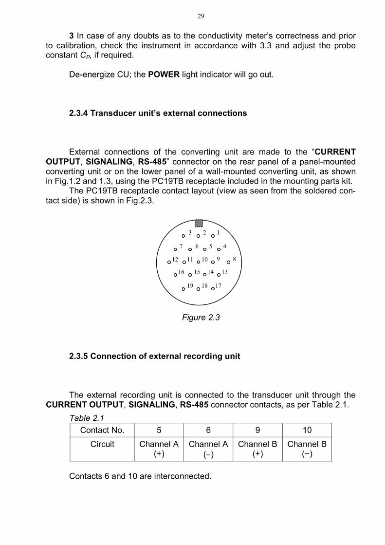
OUTPUT, SIGNALING, RS-485” connector on the rear panel of a panel-mounted converting unit or on the lower panel of a wall-mounted converting unit, as shown in Fig.1.2 and 1.3, using the PC19TB receptacle included in the mounting parts kit.
The PC19TB receptacle contact layout (view as seen from the soldered con-tact side) is shown in Fig.2.3.
Figure 2.3 2.3.5 Connection of external recording unit The external recording unit is connected to the transducer unit through the
CURRENT OUTPUT, SIGNALING, RS-485 connector contacts, as per Table 2.1. Table 2.1
Contact No. 5 6 9 10
Circuit Channel А (+)
Channel А ()
Channel В (+)
Channel В (−)
Contacts 6 and 10 are interconnected.
3
2
1
19 18 17
7
6
5
4
16 15 14 13
12 11 10 9
8

30
The 4-20 mА range load must not exceed 500 . The 0-5 mА range load must not exceed 2 k. 2.3.6 RS-485 interface connection Connection of the PC’s RS-485 port to the transducer unit is through the
CURRENT OUTPUT, SIGNALING, RS-485 connector contacts, according to Ta-ble 2.2.
Table 2.2
Contact Circuit
11 SG (signal ground)
14 DAT+ (Data +)
15 DАТ (Data )
IMPORTANT: De-energize your PC and transducer unit before connect-
ing them! Rate of exchange 19.200 bps. 2.3.7 Connection of external actuating and warning equipment Connection of external actuating and warning equipment to the transducer
unit is through the CURRENT OUTPUT, SIGNALING, RS-485 connector contacts. If the measured dissolved oxygen concentration values and analyte medium
temperature exceed the specified limits, the relay’s dry contacts close the circuits between the connector contacts, as per Table 2.3.
Threshold parameters are changed in accordance with 1.5.5. The peak switching current is 150 mА at 36 V AC.

31
Table 2.3 Controlled parameter Chan-
nel Controlled parameter value No. of contacts,
between which circuit is closed
Measured SEC value, μSm/cm Measured salinity value, ppm
А above upper limit and be-low lower limit of the cur-
rent output measuring subrange
Measured temperature value, С
above 50 С
Measured SEC value, μSm/cm Measured salinity value, ppm
В above upper limit and be-low lower limit of the cur-
rent output measuring subrange
Measured temperature value, С
above 50 С
Measured SEC value, μSm/cm Measured salinity value, ppm
А below MIN threshold value
above MAX threshold value
Measured SEC value, μSm/cm Measured salinity value, ppm
В below MIN threshold value
above MAX threshold value
2.3.8 Installation of CP-025С and CP-2С CP-003LD conductivity probes Overall and mounting dimensions of the CP-025С (CP-2С) probe are shown
in Fig.1.4. Perform the following steps to install the probes: undo cover 8 attachment screws 9 (Fig.1.4); remove probe cover 8; secure the conductivity probe so as to ensure that the analyte medium
flows via the probe from the bottom upwards (according to the arrow on the probe cover); vertical deviation of the arrow must not exceed 15;
reinstall cover 8 and tighten up screws 9; connect the probe to the sampler;
1 2
3 4
7 8
16 17
12 13
18 19

32
let flow pass through the probe until air bubbles are removed and the probe is washed; if the proposed SEC value is below 1 μSm/cm, the probe wash-ing time may reach 2 h at the maximum flow rate;
once the probe is washed, set the flow rate within a range from 3 to 30 dm3/h; the higher the proposed SEC value, the higher the flow rate to be set; with SEC of less than 5 μSm/cm the water flow rate must exceed 10 dm3/h;
repeat the same procedure to set the second probe, if it is included in the delivery set.
2.3.9 Installation of CP-003LD conductivity probe
Overall and mounting dimensions of the CP-003LD conductivity probe and the housing for probe installation in a main pipeline are shown in Fig.1.5.
An example of the CP-003LD conductivity probe installed in a main pipeline is provided in Fig.2.4. The housing should be welded into the pipeline at an angle of (45 ± 5)°.
Figure 2.4 − Example of installation of the CP-003LD conductivity probe for main pipeline measurements
Installation of the CP-003LD conductivity probe for flow-through cell meas-urements is as shown in Fig.2.5.
Housing for installation in a main pipeline
Pipeline
CP-003LD conductivity probe
Welding

33
Figure 2.5 − Installation of the CP-003LD conductivity probe in a flow-through cell
Connection to a process line is by means of a metal pipe (by welding). The
outer diameter of connections is 9 mm. The conductivity probe’s position in immersion measurements is as shown in
Fig.2.6. The analyte solution level in the container must range between 60 and 100 mm.
Figure 2.6 − Immersion measurements
2.3.10 Preparation for measurements using a hydraulic panel − in ac-cordance with ВР30.08.000РЭ
Outlet nipple connection
Flow-through cell
Inlet nipple connection
CP-003LD conductivity probe
60-1
00
CP-003LD conductivity probe

34
2.4 Measurements
To perform measurements, proceed as follows: push on the POWER switch on the front panel, the display screen will
come up; check correct setting of the conductivity meter’s parameters and operating
modes; use the CHANNEL button to select indication of channel A, channel B or
both channels. The screen indication updating time may reach 30 s. 2.5 Troubleshooting Typical failures of the conductivity meter and remedial actions are provided
in Table 2.4. If any troubles listed in Table 2.4 occur, perform the steps recommended in
the “Remedy” column. Table 2.4
Trouble Probable cause Remedy
1 Conductivity meter does not turn on.
Blown fuses For panel-mounted conductivi-ty meter – replace fuses (2.6). For wall-mounted conductivity meter − factory repair.
2 Unstable conductivity meter readings
Open cable or loose con-tact in electrode cable connector
Check and provide reliable contact or remedy the cable fault.
3 Conductivity meter overreads when measuring low SEC values
Contaminated conductivi-ty probe
Wash the conductivity probe (3.1). When changing over from high to lower SEC values, increase time of washing the conductivi-ty probe with analyte water.
Inadequate flow rate in the conductivity probe
Increase flow rate through the probe.

35
Table 2.4 continue Trouble Probable cause Remedy
4 Measured SEC or salinity value markedly different from the actual value
Conductivity probe pa-rameters are inconsistent with the set parameters of measuring channel probes
Check correct connection of probes to measuring channel connectors.
Wrongly set value of probe constant СP
Check the set probe constant value, compare it with СP value given in Table 3.1; in case of discrepancy, enter the correct probe constant value.
Open connecting cable Check contact joints at con-nectors and restore connec-tion, if necessary.
Contaminated conductivi-ty probe
Wash the conductivity probe (3.1).
Ingress of moisture into CU connector and card-boards, and into conduc-tivity probe connector contacts
Dry the converting unit or con-ductivity probe connector.
5 Measured val-ue of SEC referred to 25 С or salinity markedly different from the actual value
Probe parameters are in-consistent with the set pa-rameters of measuring channel probes
Check correct connection of probes to measuring channel connectors.
Wrongly set heat sensor resistance Rt
Invoke the parameter monitor-ing and changing mode and check the heat sensor re-sistance set. Compare it with the Rt value marked in Para. 5 and adjust it, if required.
Open connecting cable Check wire connections at the conductivity probe connector, temperature sensor connector and restore connection.
Faulty temperature sensor Factory repair Ingress of moisture into CU connector and card-boards, and into conduc-tivity probe connector
Dry the converting unit and probe connector.

36
Table 2.4 continue Trouble Probable cause Remedy
6 When measur-ing low SEC val-ues with CP-025С and CP-2С con-ductivity probes, the conductivity meter underreads
Wrong probe installation (vertical deviation angle exceeding 15)
Install the probe so as to en-sure that analyte water flows from bottom upwards with ver-tical deviation of 15 max.
7 Channel tem-perature and zeros in all digits and ranges are not in-dicated on the dis-play
Conductivity probe is off Connect the conductivity probe.
Temperature sensor break
Eliminate temperature sensor circuit fault.
8 Channel tem-perature and zeros in all digits and ranges are indi-cated on the dis-play
Conductivity probe break Eliminate the conductivity probe circuit fault.
2.6 Supply line fuses Two ВП2Б-1В (0.5 А/250 V) fuses are installed in the power transformer
primary windings. Four ВП4-3 (1 А/250 V) fuses are installed in the power transformer second-
ary windings.

37
3 MAINTENANCE 3.1 Washing of conductivity probes and temperature sensor For washing, use a washing solution that does not destroy acrylic plastic
parts stainless steel electrodes of the CP-025С (CP-2С) conductivity probe. A 1:2 ethyl alcohol-water solution is recommended. If no cleaning of oily deposits is re-quired, it is recommended to wash the probe with distilled water. Gasoline should not be used for the purpose.
Do the washing by pumping distilled water or washing solution through the CP-025С (CP-2С) conductivity probe or by multiple immersion of the CP-003LD conductivity probe into distilled water or washing solution. A brush of appropriate size may be used for the purpose.
IMPORTANT: PREVENT washing and analyte solutions from getting on
connectors! 3.2 Converting unit maintenance
The converting unit requires no maintenance. Use mild detergents to clean the CU outer surface. IMPORTANT: The transducer unit SHALL NOT be opened during the
guarantee period!
3.3 Checking the conductivity meter and adjusting the probe constant
3.3.1 Checking the transducer unit’s relative error
To check the transducer unit’s relative error, establish a set-up as depicted in Fig.3.1 below.

38
Figure 3.1 − Set-up for checking the converting unit’s relative error
Invoke the measuring mode for SEC not referred to 25 °С («χ»). Connect the С2-29В resistor with deviation not exceeding ± 0.1 % or the
Р4831 resistance box to terminals Х1 and Х2 of the simulator cable. The value of resistor connected to terminals Х1 and Х2 must vary between 0.25 and 0.3 k.
Connect a 1 k С2-29В resistor to terminals Х3 and Х4 of the simulator ca-ble.
Record the readings of the converting unit indicator χR, μSm/cm. The rated value of the converting unit indicator readings in the SEC measur-
ing mode χrated, μSm/cm, is defined with the following formula:
RСχ P
rated
310 , (3.1)
where СP value of the conductivity probe’s electrolytic constant saved to the conductivity meter memory, cm-1;
R − value of the connected resistor simulating SEC, k. The converting unit channel A (channel B) relative error χ
CUδ , %, is defined with the following formula:
% 100
R
tableRχCU χ
χχδ . (3.2)
If χCUδ , %, is within: – 0.5 ≤ CU ≤ 0.5; proceed to 3.3.2.
X1 X2 X3 X4
С2-29В resistor or P4831 resistance box
(SEC simulation)
To converting unit “Channel A” or
“Channel B” connector
C602.5 or C602LD.5 cable (depending on the conductivity
meter version) Simulator cable
(Fig. В.1 or В.2 depending on the conductivity meter version)
С2-29В resistor or Р4831 resistance box
(temperature simulation)

39
3.3.2 Probe constant check
3.3.3 To check the probe constant, establish a set-up as shown in Fig.3.2 for checking the CP-025С or CP-2С conductivity probe and as shown in Fig.3.3 for checking the CP-003LD conductivity probe.
To this end, perform the following steps: pour 0.007М KCl solution into a 3 dm3 container for CP-025С or CP-2С
conductivity probe (SEC at 25 С is 995.7 μSm/cm) and 0.0007М KCl solution for CP-003LD conductivity probe (SEC at 25 С is 102.6 μSm/cm);
place the container on the magnetic stirrer; put the reference temperature meter into the container; install the CP-025С or CP-2С conductivity probe as shown in Fig.3.2 with
a vertical deviation not exceeding 15 so as to ensure that the KCl solution flows via the CP-025С or CP-2С probe from the bottom upwards; dip the CP-003LD into the container with KCl solution as shown in Fig.3.3;
let the KCl solution flow through the reference conductivity meter’s electro-lytic cell;
place the conductivity probe, electrolytic cell and container with KCl solu-tion in the same temperature conditions (t = (20 5) С);
switch on the conductivity meter under check and enter the probe constant СP, cm-1, shown in Table 3.1;
set the value (20,000 μSm/cm) of the programmable current output meas-uring subrange;
invoke the measuring mode for SEC not referred to 25 °С («χ»); select threshold values equal to 0 μSm/cm (MIN) and 20,000 μSm/cm
(MAX); switch on the reference conductivity meter and set the desired range; disable temperature compensation of the reference conductivity meter; switch on the pump. Define the solution SEC value χref, μSm/cm, by the reference conductivity
meter and χ, μSm/cm, by the conductivity meter and conductivity probe under check.
Calculate a new value of the probe constant nPС , cm-1, using the following
formula:
rated
RrefP
nP χ
χχ
χСС (3.3)
where СP previous value of conductivity probe’s electrolytic constant saved to the conductivity meter memory, cm-1;
χref – solution SEC value defined by the reference conductivity meter, μSm/cm;
χ – solution SEC value defined by the conductivity meter under check, μSm/cm;

40
Figure 3.2 − Set-up for checking the CP-025С or CP-2С probe constant
CHANNEL А CHANNEL В CURRENT OUTPUT
SIGNALING
RS-485
CP-025С (CP-2С) conductivity probe
Electrolytic cell of reference conductivity meter
Pump
Reference temperature meter
Magnetic stirrer
Container with KCl solution
Reference conductivity meter
C602.5 cable
C602.5 cable Panel-mounted converting
unit
Wall-mounted transducer unit
CHANNEL А CHANNEL В CURRENT OUTPUT
SIGNALING
RS-485

41
Figure 3.3 − Set-up for checking the CP-003LD probe constant
CHANNEL А CHANNEL В CURRENT
OUTPUT
SIGNALING
RS-485
Panel-mounted converting unit
Wall-mounted transducer unit
CHANNEL А CHANNEL В CURRENT OUTPUT
SIGNALING
RS-485 Electrolytic cell of reference conductivity meter
Pump
Reference temperature meter
Magnetic stirrer
Container with KCl solution
Reference conductivity meter
CP-003LD conductivity probe
C602LP.5 cable
C602LD.5 cable

42
χR – readings of the indicator of CU of the conductivity meter under check, when measuring SEC with resistance simulator, μSm/cm (3.3.1);
χrated – rated readings of the indicator of CU of the conductivity meter under check with resistance simulator, μSm/cm (3.3.1).
Put the obtained value in Table 3.1 below and enter it in the conductivity me-
ter memory each time before measurement. Table 3.1
Type of conductivity
probe
Probe No.
Probe constant СP, cm-1
Date Position, name and signature
of the person checking the probe constant

43
4 DELIVERY SET The delivery set is as shown in Table 4.1.
Table 4.1 Description Code Quantity per version МАPК-
602 602/1 602LD 602LD/1 1 Converting unit ВР30.01.000 1 − 1 −
ВР42.01.000 − 1 − 1 2 Conductivity probe: CP-025С ВР30.02.000 1* 1* − − CP-2С ВР30.02.000-01 1* 1* − − CP-003LD ВР30.10.000 − − 1* 1*
3 Connecting cable: C602.5 ВР42.03.000 1** 1** − − C602.LD.5 ВР42.03.000-02 − − 1** 1**
4 Mounting parts kit: ВР30.03.100 – РС19ТВ receptacle with
housing 1 1 1 1
5 Tool and accessory kit: ВР30.04.000 HP-602 hydraulic panel ВР30.08.000 1* 1* − −
6 Tool and accessory kit: ВР30.07.000 C602.L connecting cable *** ВР42.03.000-01 1* 1* − −
7 Tool and accessory kit: ВР30.11.000 C602.LD.L
connecting cable *** ВР42.03.000-03 − − 1* 1*
8 Mounting parts kit ВР30.14.000 1 − 1 − 9 Operation Manual ВР30.00.000 1 1 1 1 *Quantity as approved by the customer. ** Quantity corresponds to that of conductivity probes. *** Length L as approved by the customer (5 to 100 m).

44
5 ACCEPTANCE CERTIFICATE
Conductivity meter MAPK-602, MAPK-602/1, MAPK-602LD, MAPK-602LD/1
(underline as appropriate) № __________________________________________
conductivity probe CP-_______________ № _____________________________
Rt=_____________________;
Conductivity probe CP-_______________ № _____________________________
Rt=_____________________.
Password – 12 is produced and accepted in accordance with government standards requirements, valid production forms and record, and considered exploitable. QC department Chief stamp here _______________ ________________ personal signature full name
“_____”____________________ 20_____.

45