map-based indoor people localization using an inertial
TRANSCRIPT

JOURNAL OF INFORMATION SCIENCE AND ENGINEERING 27, 1233-1248 (2011)
1233
Map-based Indoor People Localization using an Inertial Measurement Unit*
YUNYOUNG NAM
Center of Excellence for Ubiquitous System Ajou University
Suwon, 443-749 Korea
In this paper, we propose a new approach to map-based indoor localization for
walking people using an Inertial Measurement Unit (IMU). Generally, an office building includes various components such as corridors, rooms, floors, staircases, elevators. We consider the components for personal positioning. We present two mapping methods that are a map representation method and a position compensation method. The map repre-sentation method is applied to classification and representation of components in an in-door building map. The position compensation method is derived based on the distance and direction estimation using a dynamic scale factor. To evaluate our proposed methods, we have developed an indoor localization device using a small IMU and experimented on an office building. We show that our proposed approach achieves higher accuracy than traditional dead reckoning navigation. Keywords: indoor localization, personal positioning, inertial measurement unit, dead reckoning, foot-mounted strap-down inertial navigation, GPS-denied navigation
1. INTRODUCTION
Recent advances in wireless communication devices, sensors, and hardware tech-nology make it possible to provide various location-based services and span a wide range of fields ranging from medical and fitness, security and safety, work, learning and leisure. Reliable localization is essential for providing location-based services such as requesting for the nearest services and navigation assistance. Though positioning methods based on Global Positioning System (GPS) or mobile phone cells have been explored and stan-dardized, location-tracking of users by GPS and mobile telephony providers via GSM generates a need for more detailed location information in indoor environments. GPS is a satellite-based navigation system that provides latitude, longitude and altitude for report-ing the location. However, GPS only works outdoors and magnetic fields are often dis-turbed. In addition, cellular positioning techniques generally fail to satisfy performance requirements or accuracy. In order to overcome these problems, it is important to provide the positioning solution continuously and autonomously irrespective of any areas.
Generally, the positioning solutions have used Received Signal Strength Indicator (RSSI) signal and inertial sensors such as accelerometers in indoor environments. The RSSI-based approach is based on an estimate of the signal strength of the received elec-tromagnetic wave carrying the signal or received power, being somehow dependent on
Received April 15, 2010; revised July 14, 2010; accepted July 29, 2010. Communicated by Xiaodong Zhang. * This research was supported by the Ubiquitous Computing and Network (UCN) Project, Knowledge and Eco-
nomy Frontier R&D Program of the Ministry of Knowledge Economy (MKE), the Korean government, as a result of UCN’s subproject 11C3-T3-10M.

YUNYOUNG NAM
1234
the distance of the signal source. Although the RSSI-based approach is appealing for its low cost, the position estimate of the target probe unit is not particularly accurate. This problem can be solved by the development of inertial sensors of IMU.
Numerous researchers have proposed personal positioning methods using a combi-nation of GPS and an IMU [1-4]. The IMU measures the acceleration and rotation rate of sensors attached to the body using a 3-axis accelerometer and a gyroscope, respectively. Thus, position of the body can be derived from an attitude and a velocity. However, the Micro-Electro-Mechanical-System (MEMS) based IMU exhibits position errors that tend to increase with time in an unbounded manner because of the integral process. Therefore, an error compensation method is necessary.
In order to localize IMU-equipped only with an accelerometer and a gyroscope, three problems are addressed: (1) filtering acquired data; (2) estimating position; (3) compensating position errors. For filtering data acquired from the IMU, we applied methods including Low Pass Filter (LPF) and High Pass Filter (HPF) to the mobile de-vice. LPF can reduce the noise, smooth the small hole and even link the small break in a ridge. Then, HPF should remove any low frequency factors due to the bias voltage of output data acquired from the accelerometer and gyroscope. Lastly, the device can obtain pure acceleration and angle data.
Generally, man-made structures have straight-line features. For instance, most cor-ridors in buildings are straight and so are most walls and sidewalks alongside which a person might walk. For that reason, distance and direction of a person can be estimated by both a dead reckoning method [5, 6] and an initial position. Thus, the position of walking people can be estimated by using the distance and the direction from the initial position. For compensating position errors, we have developed two different mapping methods which are a map representation method and a position compensation method. The map representation method is to recognize physical space from architectural drawing of buildings and extracts relations of components in the indoor map. Physical space rec-ognition determines spatial relationships between structural components of building such as walls, doors, and rooms. Finally, spatial relationships between the components are represented as a graph.
This paper focuses on analyzing the personal position when the GPS signal is un-available because the signal is blocked in indoor environments. We have developed an indoor localization device based on the IMU and localization methods using a map-based mapping method and a position compensation method. The main objective of this paper is to demonstrate the feasibility of the low-cost IMU-based indoor localization system by incorporating the indoor map information. We have improved the accuracy of position-ing using spatial relationships and behavior events such as turning left and turning right. In addition, we have reduced positioning errors using a scale factor that is measured by using the estimated distance and the compensated distance. The remainder of this paper has 5 sections. We describe related work of indoor localization and the dead reckoning method in section 2. We explain indoor localization methods using the IMU in section 3. In section 4, we present position estimating methods based on topological map modeling. We show experimental results obtained with our proposed methods applied to the data from the developed device in section 5. Finally, we conclude the paper in section 6.

MAP-BASED INDOOR PEOPLE LOCALIZATION
1235
2. RELATED WORK
Numerous researchers have proposed location-based services that are predicted to become the killer application of mobile commerce [7, 8]. Early location-based services were developed based on GPS satellite access. However, if a GPS-based positioning de-vice moves from outdoor to indoor environments, the signal will likely become unavail-able and position sensing will fail. Without the location information, composite services depending on it will become unavailable as well. To arrive at seamless operation, on-the- fly switchover to an alternative position sensing service using a different technology is required.
To choose from multiple possible position sensing services, the decision has to con-sider service availability, quality of service properties, and costs. In the near future, most mobile and wearable devices are expected to have multiple position sensing technologies at disposal, such as GPS, GSM, WLAN, and Bluetooth. Nevertheless, new technologies, like at present WiMax or RFID, are continuously emerging. Thus, hardware devices and software components, their interfaces and architecture must be able to deal with changing conditions to make mobile location-based services highly available [9].
To classify indoor positioning solutions, the criteria is diverse and its applications broad. The criterions are as follows [10]: • The type of sensors: Passive or Active • The location of the position calculation: Handset or Network • The signal metrics: the Receiver Signal Strength (RSS), the Angle Of Arrival (AOA),
the Time Of Arrival (TOA) or the Time Difference Of Arrival (TDOA) To reliably and continuously track a specific person in indoor environments, there
are two kinds of location positioning systems (LPS): network-based positioning systems and independent positioning systems. Network-based positioning systems use sensor networks, mainly attached to the building. Typical network-based positioning systems are based on wireless communication such as Bluetooth [11], Ultra Wide Band (UWB) [12], WiFi [13] or RFID [14-16]. These systems have some drawbacks, including the cost of establishment and difficulty to repair. Since these techniques have the signal in-terference, accuracy of position and reorganization of distance problem, the techniques have the limitation to measure for the exactly location.
Independent positioning systems include the technologies that provide autonomous user positions, such as the dead reckoning method [17]. The dead reckoning method uses accelerometers to count steps and estimate direction using measured data of digital com-pass. 2-D position is derived from the displacement and direction. Strap-down Inertial Navigation Systems (SDINS) [18] are becoming widely used for aircraft and guided mis-sile applications. More recently this technology has been applied to not only military equipment, such as ship and submarine applications, but also indoor localization applica-tions of civilian. However, one of the problems of SDINS is the inconsistency due to cumulative location error [19]. Particularly, the heading drifts lead to large divergence from the true path. Three groups independently showed that this problem can be ad-dressed by employing known building layouts [20-22]. All used Particle Filtering (PF) methods where the building layout information is used to constrain particle movement to

YUNYOUNG NAM
1236
within the areas accessible to a pedestrian. As a result, long term error stability can be achieved when the map is sufficiently accurate and the layout sufficiently constrains the motion. The map-matching method [23] using phone compasses and accelerometers is one of recent localization approaches. However, the localization accuracy of GPS is higher than that of an IMU in outdoor environments, because people often do not walk on the street. Thus, Constandache focused on energy efficiency and showed performance of the proposed method in comparison to the WiFi based localization method.
On the other hand, some researchers have proposed vision-based positioning ap-proaches [5, 24] with single camera. To estimate the position, images are compared and matched against a pre-compiled database. If all surrounding images are stored in a data-base, the approaches could achieve higher accuracy of location. However, the approaches require potentially very large databases. Though Simultaneous Location and Mapping (SLAM) method [24] do not require a database, SLAM method may accrue errors over time and distance, and poor visibility and unfavorable light conditions can result in com-pletely false position estimation. In this paper, we deal directly with the strap down inte-gration from an IMU which is positioned at foot instep of a user and propose the inde-pendent positioning system using the map-based position compensation method to re-duce cumulative location error.
3. LOCALIZATION
Our goal is to estimate the position of a walking person using only the foot-mounted IMU and the indoor map. Fig. 1 shows the block diagram of the proposed indoor local-ization system that consists of a mobile device and an IMU. The mobile device is used for acquiring data from an accelerometer and a gyroscope in the IMU as well as estimat-ing the position. The IMU consists of sensors and a micro controller. In the micro con-troller, the analog to digital converter (ADC) transforms the analog signal to a digital signal and transfers raw data to the mobile device via a universal synchronous and asyn-chronous serial receiver and Transmitter (USART) port.
IMUSensor Micro Controller
Mobile Device
Filter
Accelerometer
Gyro
ADC
USART
Integrator
Map DB
LPF HPF
Position Estimator Location Calculator
Scale Calculator
Position Calculator
Fig. 1. The block diagram of the proposed indoor localization system.
MAP-BASED INDOOR PEOPLE LOCALIZATION
1237
Sample inde x
0 100 200 300 400 500 600 700 800 900
Vol
tage
260
280
300
320
340
360
380
400
420 Original Signal Signal after applying LPF
(a) Raw signal and signal after applying LPF.
Sample inde x
0 100 200 300 400 500 600 700 800 900
Vol
tage
- 40
- 30
- 20
- 10
0
10
20
30
40
(b) Signal after applying HPF.
Fig. 2. Signal after applying LPF and HPF.
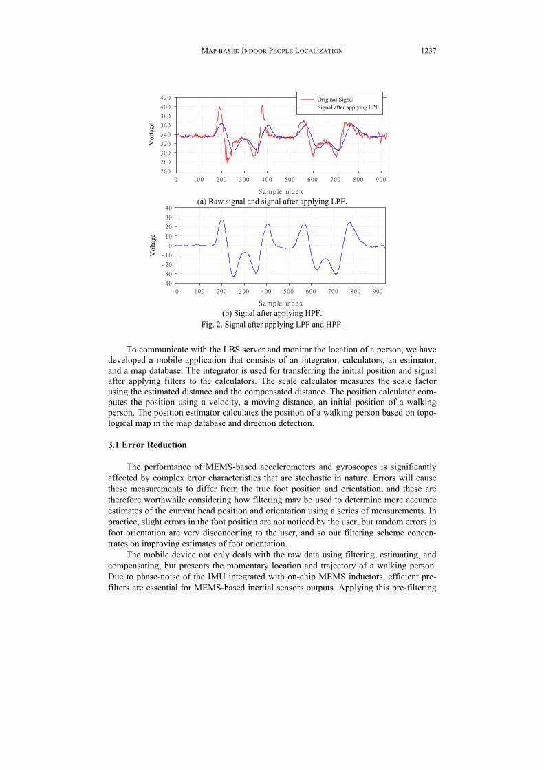
To communicate with the LBS server and monitor the location of a person, we have developed a mobile application that consists of an integrator, calculators, an estimator, and a map database. The integrator is used for transferring the initial position and signal after applying filters to the calculators. The scale calculator measures the scale factor using the estimated distance and the compensated distance. The position calculator com-putes the position using a velocity, a moving distance, an initial position of a walking person. The position estimator calculates the position of a walking person based on topo-logical map in the map database and direction detection. 3.1 Error Reduction
The performance of MEMS-based accelerometers and gyroscopes is significantly
affected by complex error characteristics that are stochastic in nature. Errors will cause these measurements to differ from the true foot position and orientation, and these are therefore worthwhile considering how filtering may be used to determine more accurate estimates of the current head position and orientation using a series of measurements. In practice, slight errors in the foot position are not noticed by the user, but random errors in foot orientation are very disconcerting to the user, and so our filtering scheme concen-trates on improving estimates of foot orientation.
The mobile device not only deals with the raw data using filtering, estimating, and compensating, but presents the momentary location and trajectory of a walking person. Due to phase-noise of the IMU integrated with on-chip MEMS inductors, efficient pre- filters are essential for MEMS-based inertial sensors outputs. Applying this pre-filtering

YUNYOUNG NAM
1238
process successfully improves signal-to-noise ratios of the sensors, removes short-term errors mixed with motion dynamics, and provides more reliable data to the MEMS inte-gration module.
Fig. 2 (a) indicates that the applied filters autocorrelation functions became much smoother after applying LPF. In order to reduce bias error, low frequency feature should be eliminated by HPF. Fig. 2 (b) shows the results of the signal filtered by using LPF and HPF. 3.2 Position Compensation
Though the best signal is obtained from LPF and HPF, the signal is not reliable to
determine the location. Due to undesirable result of drift [19, 25], the computed heading error increases continuously and without bound. In order to solve the problem, we used a Zero Velocity Update (ZUPT) that virtually eliminates the ill-effects of drift in the accel-erometers using zero velocity between steps. The ZUPT has been used successfully with update intervals between ZUPT points. In other words, when the ball of the foot is firmly on the ground, the velocity of the sole at that point is zero, that is, the energy from accel-erometer is zero. Overall energy of frequency E computed based on the 3-axis acceler-ometer is:
222zyx AAAE ++= (1)
where Ax, Ay, and Az are the energy of frequency with respect to x-axis, y-axis, and z-axis. The velocity V(x,y,z) and the distance D(x,y,z) can be computed by integrating A(x,y,z) as fol-lows,
( , , ) ( , , ) ,x y z x y ztV A dt
Δ= ∫ (2)
( , , ) ( , , ) .x y z x y ztD V dt
Δ= ∫ (3)
The trajectory can be computed by walking distance Di in interval i, and direction θ as follows,
0
1 1 1
if 0,
cos( ) if 0ii i i
x ix
x D iθ− − −
=⎧= ⎨ + ⋅ >⎩
(4)
0
1 1 1
if 0,
sin( ) if 0ii i i
y iy
y D iθ− − −
=⎧= ⎨ + ⋅ >⎩
(5)
where the coordination (x0, y0) is an initial position of a walking person.
0
1
if 0,
if 0ii
ii
θθ
θ ϕ−
=⎧= ⎨ + >⎩
(6)

MAP-BASED INDOOR PEOPLE LOCALIZATION
1239
where θ0 is the initial heading at the beginning of the walk and θi is the heading at the walk.
4. MAP-BASED POSITION ESTIMATION
Even though the position of a walking person is measured by the error reduction method and the position compensation method which are described in section 3, the typi-cal error still is largely independent of the gait or speed of a person. In practice, when walking continuously for several minutes, the position error increases gradually beyond 2%. In order to reduce increasing position errors, we have developed a map-based posi-tion estimating method depending on people movements in intersections, corridors, and dead-ends. The map-based position estimating method is composed of topological map modeling and position estimating. 4.1 Topological Map Modeling
A topological map is a concise description of the large-scale structure of the envi-ronment [26, 27]. It compactly describes the environment as a collection of places linked by paths. Topological map modeling contains the processes of extracting structural com-ponents from a map and representing topology of the components. The topological map can be represented by a graph which is composed of nodes representing topological loca-tions and edges between nodes. The topological model consists of places, paths, and re-gions explaining how the distinctive states are linked by turn and travel actions. Conse-quently, specific algorithms are required to transform a 2D map to the topological map.
To construct the topological map, line segmentation is an essential preliminary step in compact representation of structured geometric environments. Fig. 3 shows a struc-tural drawing and line segments on the 2-D terrain. After transformation of the structural drawing into line segments, our component classification algorithm classifies the line segments into intersections, corridors (lines), dead-ends, walls (blanks) as shown in Al-gorithm 1. The component classification algorithm is based on 4-connectivity that repre-sents the edge dots which are 4-neighbors of the current dot as shown in Fig. 4 (a). Fig. 4 (b) shows the component network topology represented by an undirected graph.
(a) Structural drawing. (b) Line segments.
Fig. 3. Simplified results from a structural drawing to line segments.

YUNYOUNG NAM
1240
Destination
Intersection
Line
I1
I3I2 I4
I5 I6
L1
L2
L5 L6
L7 L8L10
L4
L9 L11
L3
D1
D2 D3
D4 D5 (a) Components classified by 4-connectivity dots
structure. (b) Undirected graph of the component.
Fig. 4. 4-connectivity dots structure and component network topology represented by an undirected graph.
Algorithm 1 Component classification algorithm is based on 4-connectivity
for (x, y) = (0,0) to the size of map doif DotColor (i,j) = black then
for (x, y) = (i-1, j-1) to (i+1, j+1) docount black dots
end forif count = 2 then
MapInfo(i,j) ← dead endelse if count = 3 then
if DotColor (i-1, j) = DotColor (i+1, j) or DotColor (i,j−1) = DotColor (i, j+1)then
MapInfo(i,j) ← lineelse
MapInfo(i,j) ← intersectionend if
elseMapInfo(i,j) ← intersection {The number of black dots is over 3 (count > 3)}
end ifelse
MapInfo(i,j) ← blankend if
end for
Algorithm 2 Graph representation
for (x, y) = (0,0) to the size of MapInfo(i, j) doif MapInfo(i, j) != blank then
if MapInfo(i, j) = MapInfo(i+1, j) thenMapInfo(i+1, j) ← MapInfo(i, j)
else if MapInfo(i, j) = MapInfo(i, j+1) thenMapInfo(i, j+1) ←MapInfo(i, j)
end ifend if
end forfor (x, y) = (0,0) to the size of MapInfo(i, j) do
if MapInfo(i, j) != MapInfo(i+1, j) thenSave link information between MapInfo(i, j) and MapInfo(i+1, j)
else if MapInfo(i, j) != MapInfo(i, j+1) thenSave link information between MapInfo(i, j) and MapInfo(i, j+1)
end ifend for
MAP-BASED INDOOR PEOPLE LOCALIZATION
1241
4.2 Position Estimating Though the behavior of people walking in outdoor is less predictable, most people
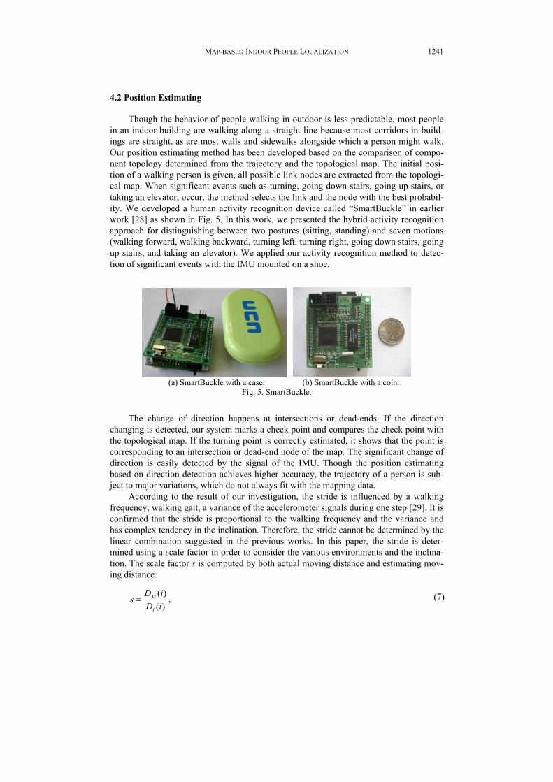
in an indoor building are walking along a straight line because most corridors in build-ings are straight, as are most walls and sidewalks alongside which a person might walk. Our position estimating method has been developed based on the comparison of compo-nent topology determined from the trajectory and the topological map. The initial posi-tion of a walking person is given, all possible link nodes are extracted from the topologi-cal map. When significant events such as turning, going down stairs, going up stairs, or taking an elevator, occur, the method selects the link and the node with the best probabil-ity. We developed a human activity recognition device called “SmartBuckle” in earlier work [28] as shown in Fig. 5. In this work, we presented the hybrid activity recognition approach for distinguishing between two postures (sitting, standing) and seven motions (walking forward, walking backward, turning left, turning right, going down stairs, going up stairs, and taking an elevator). We applied our activity recognition method to detec-tion of significant events with the IMU mounted on a shoe.
(a) SmartBuckle with a case. (b) SmartBuckle with a coin.
Fig. 5. SmartBuckle.
The change of direction happens at intersections or dead-ends. If the direction changing is detected, our system marks a check point and compares the check point with the topological map. If the turning point is correctly estimated, it shows that the point is corresponding to an intersection or dead-end node of the map. The significant change of direction is easily detected by the signal of the IMU. Though the position estimating based on direction detection achieves higher accuracy, the trajectory of a person is sub-ject to major variations, which do not always fit with the mapping data.
According to the result of our investigation, the stride is influenced by a walking frequency, walking gait, a variance of the accelerometer signals during one step [29]. It is confirmed that the stride is proportional to the walking frequency and the variance and has complex tendency in the inclination. Therefore, the stride cannot be determined by the linear combination suggested in the previous works. In this paper, the stride is deter-mined using a scale factor in order to consider the various environments and the inclina-tion. The scale factor s is computed by both actual moving distance and estimating mov-ing distance.
,)()(
iDiDs
I
M= (7)
YUNYOUNG NAM
1242
where DM(i) and DI(i) are the measured distance based on a map and the measured dis-tance based on the IMU in the interval i, respectively. Finally, the compensated position with the scale factor is calculated as:
xi = s ⋅ (xi+1 + Di-1 ⋅ cos(θi-1)), (8) yi = s ⋅ (yi+1 + Di-1 ⋅ sin(θi-1)). (9)
Since the scale factor is invariant over rotation and altitude, the positioning can be achieved by detection and measurement of human walking characterized by its stride and heading, and updating the current position and the scale factor incrementally.
5. EXPERIMENTS 5.1 Implementation
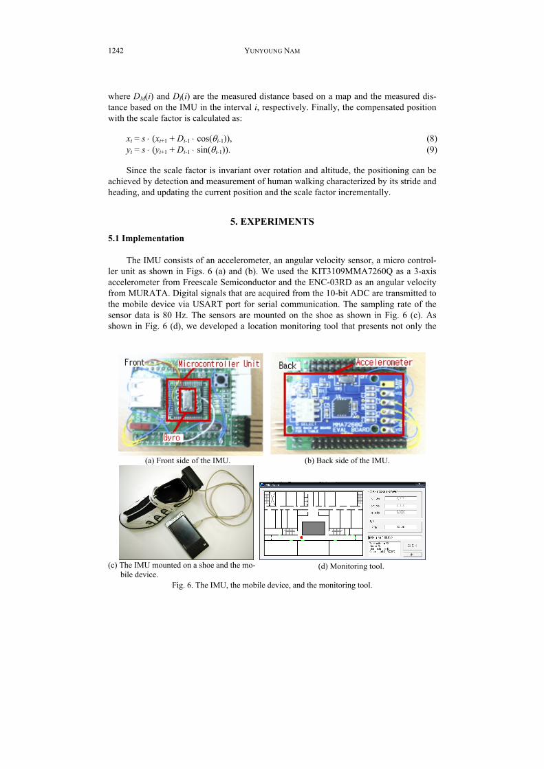
The IMU consists of an accelerometer, an angular velocity sensor, a micro control-
ler unit as shown in Figs. 6 (a) and (b). We used the KIT3109MMA7260Q as a 3-axis accelerometer from Freescale Semiconductor and the ENC-03RD as an angular velocity from MURATA. Digital signals that are acquired from the 10-bit ADC are transmitted to the mobile device via USART port for serial communication. The sampling rate of the sensor data is 80 Hz. The sensors are mounted on the shoe as shown in Fig. 6 (c). As shown in Fig. 6 (d), we developed a location monitoring tool that presents not only the
(a) Front side of the IMU. (b) Back side of the IMU.
(c) The IMU mounted on a shoe and the mo-
bile device. (d) Monitoring tool.
Fig. 6. The IMU, the mobile device, and the monitoring tool.

MAP-BASED INDOOR PEOPLE LOCALIZATION
1243
current status of an accelerometer and a gyro sensor with an indoor map, but the number of intersections, corridors, and dead-ends. In addition, the current position of a walker is marked on the map by a red dot. 5.2 Experimental Results for Various Strides
To evaluate our position estimating method, we have conducted experiments on
three different types of step length which are 0.5 meters, 0.7 meters, and 0.9 meters as shown in Fig. 7. As shown in Fig. 7, we observe two kinds of patterns which are peak patterns and valley patterns. The peak patterns are caused by the foot being lifted off the ground or the leg settling back on the ground. When the step length is 0.5 meters, 0.7 meters, and 0.9 meters, most peak voltage ranges from 200 to 300, 250 to 350, and 250 to 450, respectively. The valley patterns are caused by zero velocity between steps. In the valley patterns, overall energy of frequency and the velocity of the sole are zero. Due to minute of movements and phase-noise of the IMU integrated with on-chip MEMS in-ductors, overall energy is not always zero. In this paper, we set the fundamental voltage value to zero when the signal voltage is less than 10 for a period of time. Step events are detected using a custom algorithm (outside the scope of this paper) based on thresholds and some heuristics to ensure robustness. The parameters of the algorithm are tuned to maximize the detection accuracy of a certain person in a normal walk mode.
Time
0 50 100 150 200 250 300
Vol
tage
0
50
100
150
200
250
300
Accelerometer signalStep detection
Vol
tage
Time
0 50 100 150 200 250 300
Vol
tage
0
100
200
300
400
Accelerometer signalStep detection
(a) Step length = 0.5m. (b) Step length = 0.7m.
(c) Step length = 0.9m.
Fig. 7. Accelerometer output signal of various strides.
YUNYOUNG NAM
1244
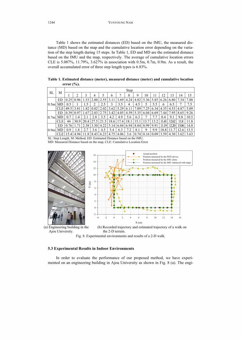
Table 1 shows the estimated distances (ED) based on the IMU, the measured dis-tance (MD) based on the map and the cumulative location error depending on the varia-tion of the step length during 15 steps. In Table 1, ED and MD are the estimated distance based on the IMU and the map, respectively. The average of cumulative location errors CLE is 5.087%, 11.79%, 3.627% in association with 0.5m, 0.7m, 0.9m. As a result, the overall accumulated error of three step length types is 6.83%.
Table 1. Estimated distance (meter), measured distance (meter) and cumulative location error (%).
Step SL M
1 2 3 4 5 6 7 8 9 10 11 12 13 14 15 ED 0.25 0.96 1.53 2.00 2.55 3.11 3.69 4.24 4.82 5.36 5.85 6.26 6.80 7.34 7.88 MD 0.5 1 1.5 2 2.5 3 3.5 4 4.5 5 5.5 6 6.5 7 7.5 0.5m CLE 49.5 3.81 1.82 0.02 2.02 3.62 5.29 6.11 7.09 7.25 6.34 4.35 4.53 4.87 5.09 ED 0.39 0.97 1.67 2.03 2.75 3.42 4.05 4.59 5.35 6.04 6.69 7.44 7.95 8.65 9.26 MD 0.7 1.4 2.1 2.8 3.5 4.2 4.9 5.6 6.3 7 7.7 8.4 9.1 9.8 10.5 0.7m CLE 44 30.9 20.4 27.5 21.5 18.6 17.4 18.1 15.1 13.7 13.2 11.41 12.62 11.8 11.8 ED 0.76 1.71 2.38 3.30 4.22 5.14 6.04 6.94 8.04 8.99 9.91 11.19 12.20 13.06 14.0 MD 0.9 1.8 2.7 3.6 4.5 5.4 6.3 7.2 8.1 9 9.9 10.8 11.7 12.6 13.5 0.9m CLE 15.4 4.94 11.8 8.43 6.23 4.75 4.06 3.6 0.74 0.16 0.09 3.59 4.30 3.62 3.63
SL: Step Length, M: Method, ED: Estimated Distance based on the IMU, MD: Measured Distance based on the map, CLE: Cumulative Location Error
X (m)
-4 -2 0 2 4 6 8 10 12 14 16
Y (m
)
-2
0
2
4
6
8
10
12
14
16 Actual positionPosition measured by the WiFi devicePosition measured by the IMU alonePosition measured by the IMU enhanced with maps
(a) Engineering building in the
Ajou University. (b) Recorded trajectory and estimated trajectory of a walk on
the 2-D terrain. Fig. 8. Experimental environments and results of a 2-D walk.
5.3 Experimental Results in Indoor Environments In order to evaluate the performance of our proposed method, we have experi-
mented on an engineering building in Ajou University as shown in Fig. 8 (a). The engi-

MAP-BASED INDOOR PEOPLE LOCALIZATION
1245
neering building has four floors with an inner-courtyard. To present experimental results on level terrain (2-D), a user equipped with the IMU and the mobile device walked along a rectangle-shaped path in counterclockwise. We ran five experiments on the path with base length 14 meters and height 10 meters. Fig. 8 (b) shows recorded trajectory and es-timated trajectory of a walker in comparison with the WiFi device, the IMU enhanced with maps, and the IMU alone. The variation of position error PE measured by the WiFi device ranges from 0 meter to 18.98 meters.
PE(ti) = distance(Estimated Position(ti), Actual Position(ti)) (10)
The average of PE measured by the WiFi device is 10.05 meters. The differences between the WiFi based localization and IMU based localization are visually apparent. Due to multi-path effects, interference and absorption, positioning method with WiFi signals is hampered by non-linearity, noise and complex correlations. The variation of PE measured by the IMU alone ranges from 0.032 meters to 2.818 meters. The variation of PE measured by the IMU enhanced with maps ranges from 0 meter to 0.26 meter. The average of PE measured by the IMU alone and the IMU enhanced with maps is 0.98 me-ters and 0.096 meters, respectively. The accuracy of position measured by the IMU en-hanced with maps is 10.2 times higher than that of position measured by the IMU alone.
Table 2. Component network topology transformed from a structural drawing. Link information Component information
I1:L66:L1:L66:L1: I1:7:7:7:7: L1:I1:I2:I1:I2: L1:7:8:7:9:7:10: … 7:72: I2:L67:L1:L67:L1: I2:7:73:7:73: L66:I1:I3:I1:I3: L66:8:7:9:7:10:7: … 18:7: L67:I2:I4:I2:I4: L67:8:73:9:73:10:73: … 24:73: I3:L88:L66:L88:L66: I3:19:7:19:7: L88:I3:D1:I3:D1: L88:19:8:19:9:19:10: … 19:51: D1:L88:L88: D1:19:52:19:52: I4:L145:L138:L67:L145:L138:L67: I4:25:73:25:73: L138:I4:D2:I4:D2: L138:25:74:25:75: … 25:80: D2:L138:L138: D2:25:81:25:81: L145:I4:I5:I4:I5: L145:26:73:27:73: … 63:73: D3:L155:L155: D3:34:207:34:207: L155:D3:I7:D3:I7: L155:35:207:36:207: … 69:207:
… …
Table 2 shows the result of the component network topology transformed from a structural drawing of the building. In this table, an intersection I1 that is located at the point (7, 7) has corridors L66 and L1. On the other hand, the corridor L1 has intersec-tions I1 and I2. The L1 is a pathway from the position (7, 8) to the position (7, 72). Fur-thermore, to show results of an experiment on level terrain (3-D), five volunteers par-

YUNYOUNG NAM
1246
ticipated in the experiment. Fig. 9 shows a 3-D plot of the trajectory. They went down stairs from the 4th floor to the 3rd floor, and went up stairs from the 3rd floor to the 4th floor. Total distance of walking path is 637.5 meters. The variation of PE ranges from 0 meter to 0.28 meters. The average of PE is 2.278 meters. The experimental results show that our proposed method estimates the position over multiple floors and improves the positioning accuracy based on the detection of significant events such as going down stairs and going up stairs.
6. CONCLUSION
In this paper, we have proposed the indoor localization method based on the topo-logical map modeling for providing a real-time position of walking people. We devel-oped not only the position compensation method using error reduction filters and ZUPT, but the map-representation method for constructing the topological map. Although the limited performance of the IMU based on dead reckoning has given less accurate posi-tioning results, we have proposed the map-based position estimating method depend on movements of walking people to improve the positioning accuracy. In the experiments, we have developed foot-mounted strap-down inertial navigation system to demonstrate the feasibility of the low-cost IMU-based device. In addition, we showed that our pro-posed methods achieve a significant improvement of the positioning accuracy compared to the use of the IMU alone.
ACKNOWLEDGEMENT
The author would like to thank Brittany Ryzuk for previewing of our manuscript.
REFERENCES
1. Q. Ladetto, V. Gabaglio, and B. Merminod, “Combining gyroscopes, magnetic com- pass and GPS for pedestrian navigation,” in Proceedings of International Symposium on Kinematic Systems in Geodesy, Geomatics and Navigation, 2001, pp. 205-212.
2. S. Cho, K. Lee, C. Park, and J. Lee, “A personal navigation system using low-cost mems/gps/fluxgate,” in Institute of Navigation Annual Meeting, 2003, pp. 122-127.
3. S. Y. Cho and C. G. Park, “Mems based pedestrian navigation system,” The Journal of Navigation, Vol. 59, 2006, pp. 135-153.
4. F. Cavallo, A. Sabatini, and V. Genovese, “A step toward gps/ins personal naviga-tion systems: real-time assessment of gait by foot inertial sensing,” in Proceedings of IEEE/RSJ International Conference on Intelligent Robots and Systems, 2005, pp. 1187-1191.
5. M. Kourogi and T. Kurata, “Personal positioning based on walking locomotion analysis with self-contained sensors and a wearable camera,” in Proceedings of the 2nd IEEE and ACM International Symposium on Mixed and Augmented Reality, 2003, pp. 103-112.
6. E. Foxlin, “Pedestrian tracking with shoe-mounted inertial sensors,” Computer Gra-

MAP-BASED INDOOR PEOPLE LOCALIZATION
1247
phics and Applications, Vol. 25, 2005, pp. 38-46. 7. P. Kannan, A. M. Chang, and A. Whinston, “Wireless commerce: marketing issues
and possibilities,” in Proceedings of the 34th Annual Hawaii International Confer-ence on System Sciences, 2001, pp. 6.
8. B. Kolmel, “Location based services,” in Proceedings of Workshop Mobile Com-merce, 2003, pp. 88-101.
9. P. Ibach, G. Tamm, and M. Horbank, “Dynamic value webs in mobile environments using adaptive location-based services,” in Proceedings of the 38th Annual Hawaii International Conference on System Sciences, 2005, pp. 208.
10. V. Renaudin, O. Yalak, P. Tome, and B. Merminod, “Indoor navigation of emer-gency agents,” European Journal of Navigation, Vol. 5, 2007, pp. 36-45.
11. A. Kotanen, M. Hannikainen, H. Leppakoski, and T. D. Hamalainen, “Experiments on local positioning with bluetooth,” in Proceedings of the International Conference on Information Technology: Computers and Communications, 2003, pp. 297.
12. D. B. Jourdan, J. J. Deyst, Jr., M. Z. Win, and N. Roy, “Monte carlo localization in dense multipath environments using uwb ranging,” in Proceedings of IEEE Interna-tional Conference on Ultra-Wideband, 2005, pp. 314-319.
13. A. M. Ladd, K. E. Bekris, A. Rudys, G. Marceau, L. E. Kavraki, and D. S. Wallach, “Robotics-based location sensing using wireless ethernet,” in Proceedings of the 8th Annual International Conference on Mobile Computing and Networking, 2002, pp. 227-238.
14. L. M. Ni, Y. Liu, Y. C. Lau, and A. P. Patil, “Landmarc: indoor location sensing using active rfid,” Wireless Network, Vol. 10, 2004, pp. 701-710.
15. C. Alippi, A. Mottarella, and G. Vanini, “A RF map-based localization algorithm for indoor environments,” in Proceedings of IEEE International Symposium on Circuits and Systems, Vol. 1, 2005, pp. 652-655.
16. M. Kourogi, N. Sakata, T. Okuma, and T. Kurata, “Indoor/outdoor pedestrian naviga- tion with an embedded gps/rfid/self-contained sensor system,” in Proceedings of the 16th International Conference on Artificial Reality and Telexistence, 2006, pp. 1310- 1321.
17. L. Ojeda and J. Borenstein, “Personal dead-reckoning system for gps-denied environ- ments,” in Proceedings of IEEE International Workshop on Safety, Security and Res-cue Robotics, 2007, pp. 1-6.
18. D. Titterton and J. Weston, “Strapdown inertial navigation technology − 2nd edition − [book review],” IEEE Aerospace and Electronic Systems Magazine, Vol. 20, 2005, pp. 33-34.
19. A. Sabatini, C. Martelloni, S. Scapellato, and F. Cavallo, “Assessment of walking features from foot inertial sensing,” IEEE Transactions on Biomedical Engineering, Vol. 52, 2005, pp. 486-494.
20. O. Woodman and R. Harle, “Pedestrian localisation for indoor environments,” in Proceedings of UbiComp, 2008, pp. 114-123.
21. S. Beauregard, Widyawan, and M. Klepal, “Indoor pdr performance enhancement using minimal map information and particle filters,” in Proceedings of IEEE/ION Position, Location and Navigation Symposium, 2008, pp. 141-147.
22. B. Krach and P. Roberston, “Cascaded estimation architecture for integration of foot-mounted inertial sensors,” in Proceedings of IEEE/ION Position, Location and

YUNYOUNG NAM
1248
Navigation Symposium, 2008, pp. 112-119. 23. I. Constandache, R. Choudhury, and I. Rhee, “Towards mobile phone localization
without war-driving,” in Proceedings of IEEE Infocom, 2010, pp. 2321-2329. 24. J. Folkesson, P. Jensfelt, and H. Christensen, “Vision slam in the measurement sub-
space,” in Proceedings of IEEE International Conference on Robotics and Automa-tion, 2005, pp. 30-35.
25. J. Borenstein, L. Ojeda, and S. Kwanmuang, “Heuristic reduction of gyro drift for personnel tracking systems,” The Journal of Navigation, Vol. 62, 2009, pp. 41-58.
26. B. Kuipers and Y. T. Byun, “A robot exploration and mapping strategy based on a semantic hierarchy of spatial representations,” Journal of Robotics and Autonomous Systems, 1991, Vol. 8, pp. 47-63.
27. H. Choset and K. Nagatani, “Topological simultaneous localization and mapping (SLAM): Toward exact localization without explicit localization,” IEEE Transac-tions on Robotics and Automation, Vol. 17, 2001, pp. 125-137.
28. Y. Cho, Y. Nam, Y. J. Choi, and W. D. Cho, “Smartbuckle: human activity recogni-tion using a 3-axis accelerometer and a wearable camera,” in Proceedings of the 2nd International Workshop on Systems and Networking Support for Health Care and Assisted Living Environments, 2008, pp. 1-3.
29. E. Ayyappa, “Normal human locomotion, part 1: Basic concepts and terminology,” Journal of Prosthetics and Orthotics, Vol. 9, 1997, pp. 10-17.
Yunyoung Nam (南潤榮) received B.S., M.S. and Ph.D. degree in Computer Engineering from Ajou University, Korea in 2001, 2003, and 2007 respectively. He was a research engineer in the Center of Excellence in Ubiquitous System from 2007 to 2009. He was a post-doctoral researcher at Stony Brook University in 2009, New York. He is currently a research professor in Ajou University in Korea. He also spent time as a visiting scholar at Stony Brook University − State University of New York Stony Brook, New York. His research interests include multimedia da-tabase, ubiquitous computing, image processing, pattern recogni- tion, context-awareness, wearable computing, and intelligent video surveillance.