manual protocol converter/ babelstar modbus - … · manual – protocol converter - babelstar...
TRANSCRIPT
Manual
Protocol Converter/ Babelstar
MODBUS – SDI-12 & MODBUS – HSIO
Model 6543A
Revision History
File name / Revision Date Author & Change Details Checked/Approved
Previous version BX 2004 RS/ JH
Unidata Manual - 6543 Protocol Converter Manual Issue 2.0 2007 AB/CB/JH/MS/KC
Unidata Manual - 6543 Protocol Converter Manual Issue 3.0 2013 DM
Unidata Manual - 6543 Protocol Converter Manual Issue 4.0 25/09/2013 MP
Unidata Manual - 6543A Protocol Converter Issue 4.0.docx 30 01 15 IM,CB Update CB
Copyright © Unidata Pty Ltd 2000-2013. All rights reserved. No part of this publication may be reproduced, transmitted, transcribed, stored in a retrieval system, or translated into any spoken or computer language, in any form or by any means. Electronic, mechanical, magnetic, optical, chemical, manual or otherwise, without prior written permission of Unidata Pty Ltd 40 Ladner St, O’Connor Western Australia 6163.
Manual – Protocol Converter - Babelstar Model 6543A
Unidata Manual - 6543A Protocol Converter Issue 4.0.docx Contents 1
TABLE OF CONTENTS
1.0 Introduction ......................................................................................................................... 1 1.1 Modbus to SDI-12 Conversion ............................................................................................ 1 1.2 Modbus to HSIO Conversion ............................................................................................... 1
2.0 Requirements ...................................................................................................................... 2
3.0 Specifications ...................................................................................................................... 3
4.0 Installation ........................................................................................................................... 4 4.1 Wiring .................................................................................................................................. 4 4.2 Connections ......................................................................................................................... 5 4.3 Settings ................................................................................................................................ 6
5.0 System Operation ............................................................................................................... 8 5.1 SDI-12 Instrument Power-Up .............................................................................................. 8 5.2 Multiple SDI-12 Instruments ................................................................................................ 9 5.3 Modbus RTU Data Format .................................................................................................. 9 5.4 SDI-12 Conversion - Suggested Operation Sequence ....................................................... 9
6.0 Appendix A – Modbus / SDI-12 Conversion Tables & Examples .................................. 10 6.1 Modbus RTU Signed Decimal / SDI-12 Conversion Table ............................................... 10 6.2 Modbus RTU Floating-Point / SDI-12 Conversion Table .................................................. 11 6.3 Modbus RTU / HSIO Conversion Table ............................................................................ 12
7.0 Appendix B - SCADA Configuration ................................................................................ 13 7.1 SDI-12 Integer Example .................................................................................................... 13 7.2 SDI-12 Floating point example .......................................................................................... 16 7.3 Additional Measurements (Firmware version 11 and above) ............................................ 19 7.4 Return of Multiple Measurements (aD1!...aD9!) ................................................................ 21
Manual – Protocol Converter - Babelstar Model 6543A
Unidata Manual - 6543A Protocol Converter Issue 4.0.docx Page 1
1.0 INTRODUCTION
The Model 6543A Protocol Convertor - BabelStar converts Modbus to SDI-12 requests OR converts HSIO data to Modbus data. The function desired is selected with DIP SW 6.
1.1 Modbus to SDI-12 Conversion
The Model 6543A Protocol Converter is designed to act as a Modbus slave on a Modbus RTU bus (Note: Modbus ASCII is not supported). On receipt of certain Modbus commands the Protocol Converter module initiates SDI-12 commands – awaits the response and returns the results as Modbus values. The data returned is in Modbus RTU and selectable as either a binary decimal values with a sign delimiter or as a binary floating point value.
1.2 Modbus to HSIO Conversion
The Model 6543A Protocol Converter is designed to act as a Modbus slave on a Modbus RTU bus (Note: Modbus ASCII is not supported) and as a HSIO slave on the HSIO connection from a Unidata logger or Starflow. On receipt of HSIO data the Protocol Converter module stores the HSIO data into memory. On receipt of certain Modbus commands, the Protocol Converter returns the requested memory values as Modbus values. The data returned is in Modbus RTU format and is returned as an exact representation of the HSIO value/s received.
Manual – Protocol Converter - Babelstar Model 6543A
Unidata Manual - 6543A Protocol Converter Issue 4.0.docx Page 2
2.0 REQUIREMENTS
The Protocol Converter requires a 5 to 24 volt power source capable of supplying a 15 mA load. SDI-12 range may be degraded slightly if power source is below 5.5 volts.
The Protocol Converter Slave ID must be set with DIP Switches 1 to 4 – only slave addresses 0 to 15 are supported.
The Modbus RTU protocol data conversion type must be set with DIP Switches 5 to 6 – IEEE 32 Bit floating point and 2’s complement 16 bit signed integers are supported.
The input conversion type (SDI-12 or HSIO) must be selected with SW 6.
The type of the Modbus communication device (RS232/RS485) must be declared with SW7.
The baud rate supported on the Modbus RTU connection is 9600 and 19,200 bps. This is set with DIP Switch 8. The SDI-12 baud rate is fixed to the standard baud rate of 1200 bps.
Manual – Protocol Converter - Babelstar Model 6543A
Unidata Manual - 6543A Protocol Converter Issue 4.0.docx Page 3
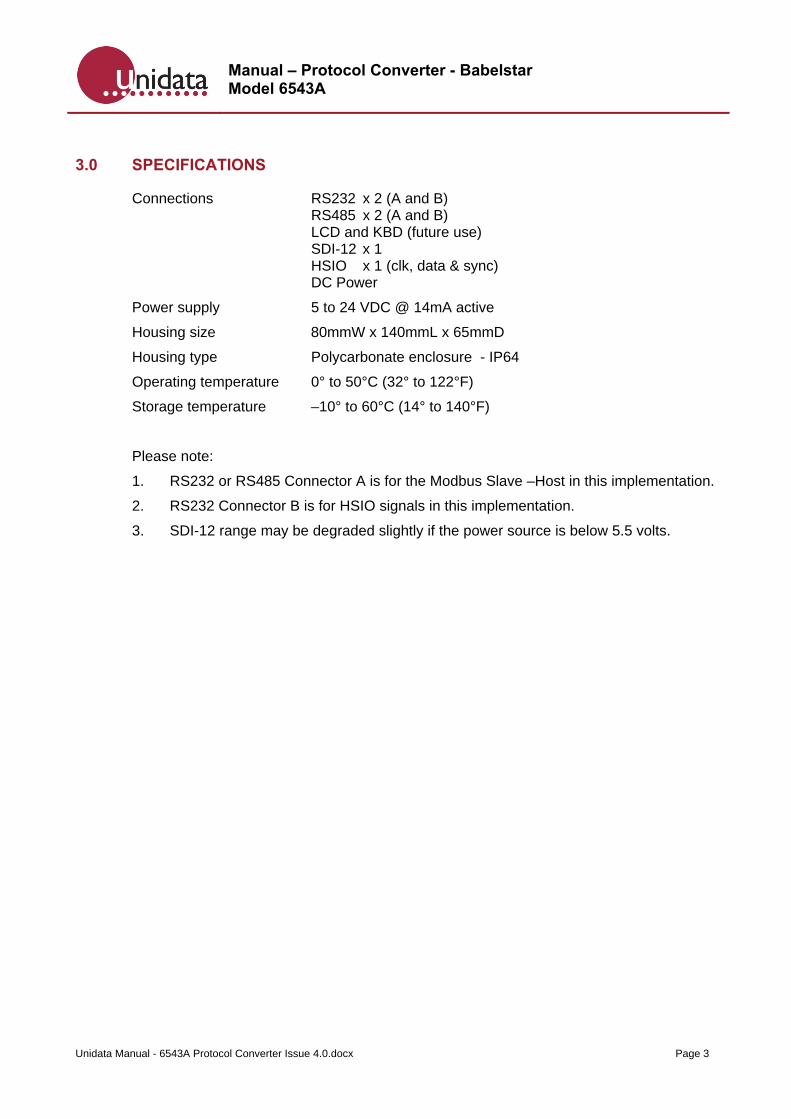
3.0 SPECIFICATIONS
Connections RS232 x 2 (A and B) RS485 x 2 (A and B) LCD and KBD (future use) SDI-12 x 1 HSIO x 1 (clk, data & sync) DC Power
Power supply 5 to 24 VDC @ 14mA active
Housing size 80mmW x 140mmL x 65mmD
Housing type Polycarbonate enclosure - IP64
Operating temperature 0° to 50°C (32° to 122°F)
Storage temperature –10° to 60°C (14° to 140°F)
Please note:
1. RS232 or RS485 Connector A is for the Modbus Slave –Host in this implementation.
2. RS232 Connector B is for HSIO signals in this implementation.
3. SDI-12 range may be degraded slightly if the power source is below 5.5 volts.
Manual – Protocol Converter - Babelstar Model 6543A
Unidata Manual - 6543A Protocol Converter Issue 4.0.docx Page 4
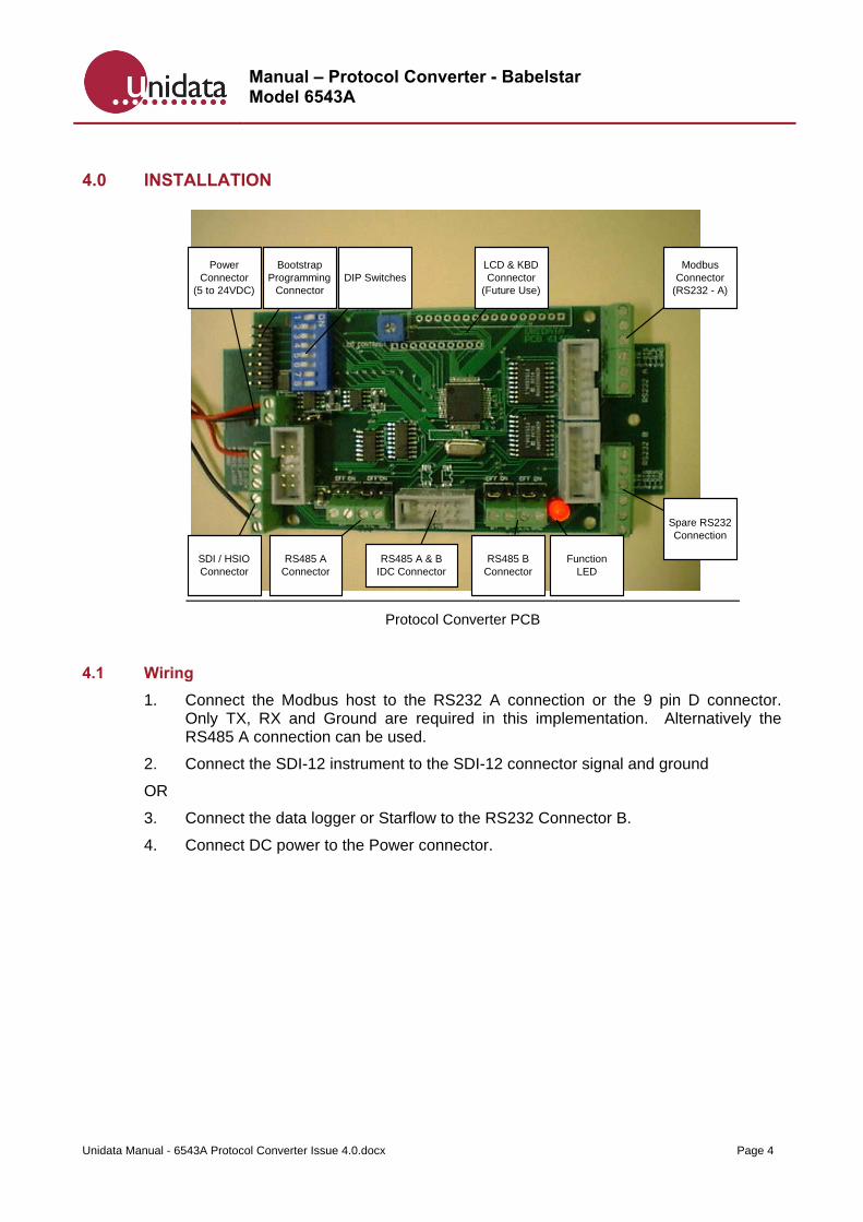
4.0 INSTALLATION
ModbusConnector
(RS232 - A)
Power Connector
(5 to 24VDC)
SDI / HSIO Connector
Bootstrap Programming
Connector
FunctionLED
DIP Switches
RS485 A Connector
RS485 BConnector
RS485 A & BIDC Connector
LCD & KBDConnector
(Future Use)
Spare RS232Connection
Protocol Converter PCB
4.1 Wiring
1. Connect the Modbus host to the RS232 A connection or the 9 pin D connector. Only TX, RX and Ground are required in this implementation. Alternatively the RS485 A connection can be used.
2. Connect the SDI-12 instrument to the SDI-12 connector signal and ground
OR
3. Connect the data logger or Starflow to the RS232 Connector B.
4. Connect DC power to the Power connector.
Manual – Protocol Converter - Babelstar Model 6543A
Unidata Manual - 6543A Protocol Converter Issue 4.0.docx Page 5
4.2 Connections
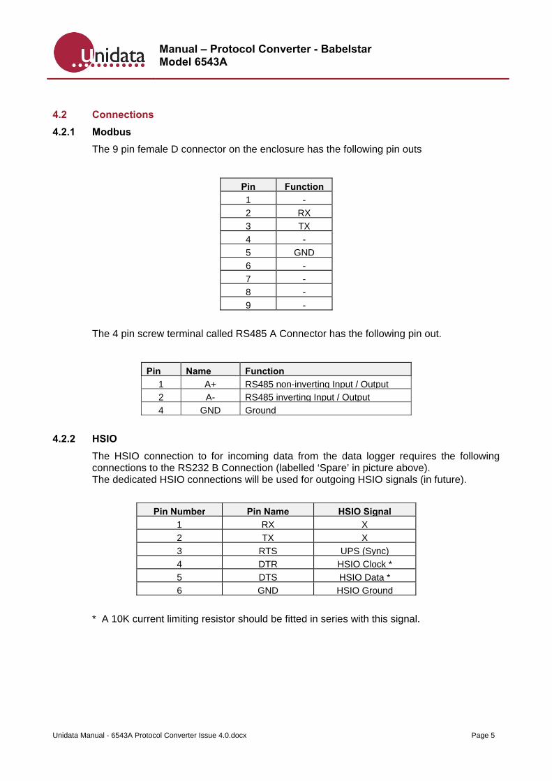
4.2.1 Modbus
The 9 pin female D connector on the enclosure has the following pin outs
Pin Function
1 -
2 RX
3 TX
4 -
5 GND
6 -
7 -
8 -
9 -
The 4 pin screw terminal called RS485 A Connector has the following pin out.
Pin Name Function
1 A+ RS485 non-inverting Input / Output
2 A- RS485 inverting Input / Output
4 GND Ground
4.2.2 HSIO
The HSIO connection to for incoming data from the data logger requires the following connections to the RS232 B Connection (labelled ‘Spare’ in picture above). The dedicated HSIO connections will be used for outgoing HSIO signals (in future).
Pin Number Pin Name HSIO Signal
1 RX X
2 TX X
3 RTS UPS (Sync)
4 DTR HSIO Clock *
5 DTS HSIO Data *
6 GND HSIO Ground
* A 10K current limiting resistor should be fitted in series with this signal.
Manual – Protocol Converter - Babelstar Model 6543A
Unidata Manual - 6543A Protocol Converter Issue 4.0.docx Page 6
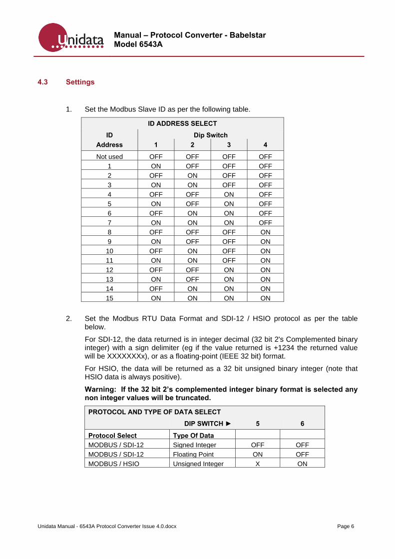
4.3 Settings
1. Set the Modbus Slave ID as per the following table.
ID ADDRESS SELECT
ID Dip Switch
Address 1 2 3 4
Not used OFF OFF OFF OFF
1 ON OFF OFF OFF
2 OFF ON OFF OFF
3 ON ON OFF OFF
4 OFF OFF ON OFF
5 ON OFF ON OFF
6 OFF ON ON OFF
7 ON ON ON OFF
8 OFF OFF OFF ON
9 ON OFF OFF ON
10 OFF ON OFF ON
11 ON ON OFF ON
12 OFF OFF ON ON
13 ON OFF ON ON
14 OFF ON ON ON
15 ON ON ON ON
2. Set the Modbus RTU Data Format and SDI-12 / HSIO protocol as per the table below.
For SDI-12, the data returned is in integer decimal (32 bit 2's Complemented binary integer) with a sign delimiter (eg if the value returned is +1234 the returned value will be XXXXXXXx), or as a floating-point (IEEE 32 bit) format.
For HSIO, the data will be returned as a 32 bit unsigned binary integer (note that HSIO data is always positive).
Warning: If the 32 bit 2’s complemented integer binary format is selected any non integer values will be truncated.
PROTOCOL AND TYPE OF DATA SELECT
DIP SWITCH ► 5 6
Protocol Select Type Of Data
MODBUS / SDI-12 Signed Integer OFF OFF
MODBUS / SDI-12 Floating Point ON OFF
MODBUS / HSIO Unsigned Integer X ON
Manual – Protocol Converter - Babelstar Model 6543A
Unidata Manual - 6543A Protocol Converter Issue 4.0.docx Page 7
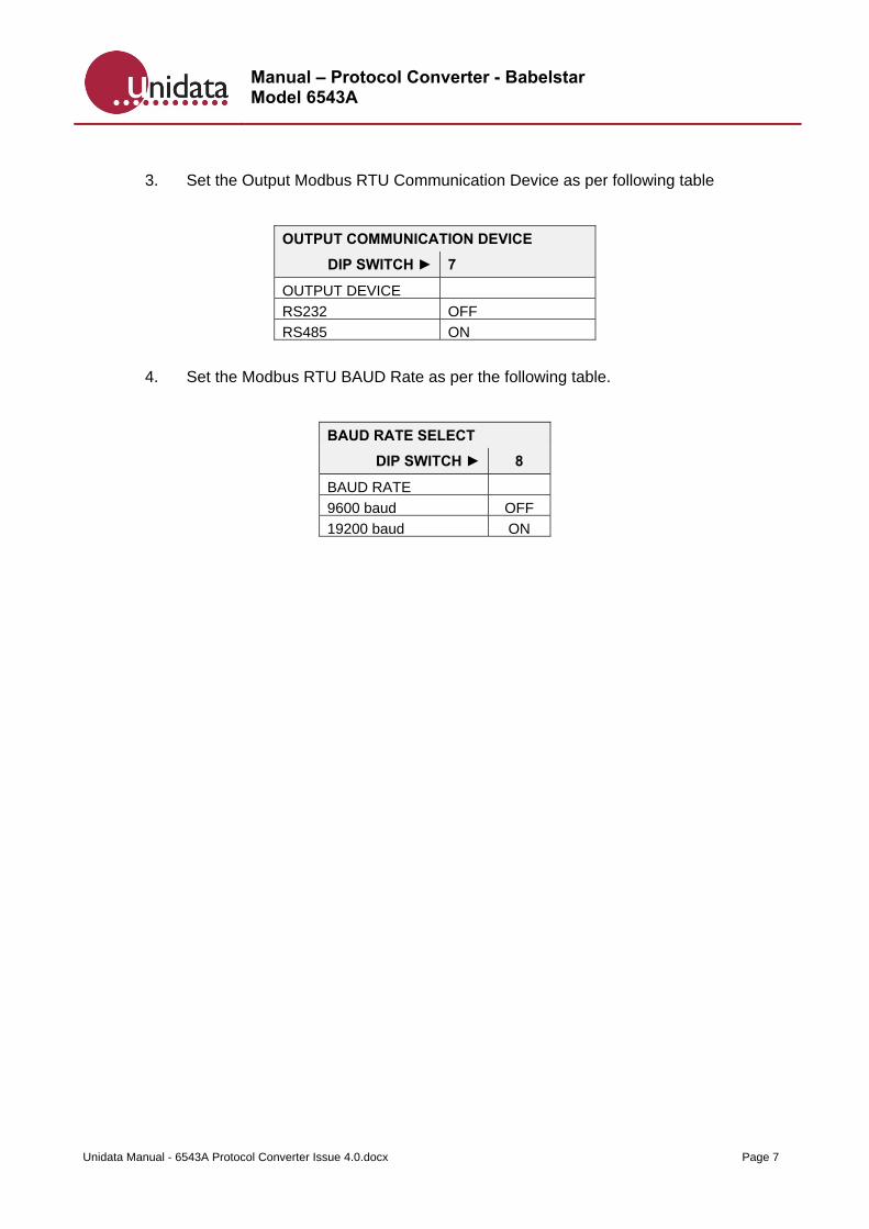
3. Set the Output Modbus RTU Communication Device as per following table
OUTPUT COMMUNICATION DEVICE
DIP SWITCH ► 7
OUTPUT DEVICE
RS232 OFF
RS485 ON
4. Set the Modbus RTU BAUD Rate as per the following table.
BAUD RATE SELECT
DIP SWITCH ► 8
BAUD RATE
9600 baud OFF
19200 baud ON
Manual – Protocol Converter - Babelstar Model 6543A
Unidata Manual - 6543A Protocol Converter Issue 4.0.docx Page 8
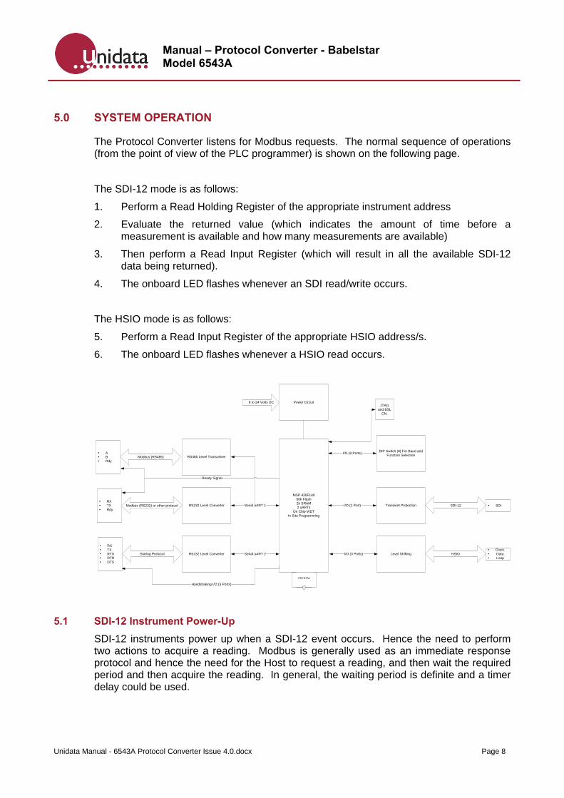
5.0 SYSTEM OPERATION
The Protocol Converter listens for Modbus requests. The normal sequence of operations (from the point of view of the PLC programmer) is shown on the following page.
The SDI-12 mode is as follows:
1. Perform a Read Holding Register of the appropriate instrument address
2. Evaluate the returned value (which indicates the amount of time before a measurement is available and how many measurements are available)
3. Then perform a Read Input Register (which will result in all the available SDI-12 data being returned).
4. The onboard LED flashes whenever an SDI read/write occurs.
The HSIO mode is as follows:
5. Perform a Read Input Register of the appropriate HSIO address/s.
6. The onboard LED flashes whenever a HSIO read occurs.
5.1 SDI-12 Instrument Power-Up
SDI-12 instruments power up when a SDI-12 event occurs. Hence the need to perform two actions to acquire a reading. Modbus is generally used as an immediate response protocol and hence the need for the Host to request a reading, and then wait the required period and then acquire the reading. In general, the waiting period is definite and a timer delay could be used.
MSP 430F14960k Flash2k SRAM2 uARTs
On Chip WDTIn Situ Programming
RS232 Level Converter Transient Protection
RS232 Level Converter
Modbus (RS232) or other protocol
Starlog Protocol Level Shifting
SDI-12
HSIO
RS485 Level Transceiver
Serial uART 1
Serial uART 2
Modbus (RS485)
I/O (3 Ports)
I/O (1 Port)
Clock Data Loop
SDI
Power Circuit6 to 24 Volts DC
DIP Switch (8) For Baud andFunction Selection
I/O (8 Ports)
Handshaking I/O (3 Ports)
RX TX RTS DTR DTS
RX TX Rdy
A B Rdy
JTAGand BSL
CN.
CRYSTAL
Ready Signal
Manual – Protocol Converter - Babelstar Model 6543A
Unidata Manual - 6543A Protocol Converter Issue 4.0.docx Page 9
5.2 Multiple SDI-12 Instruments
Multiple instruments can be connected to the SDI-12 bus hence the need to address the instruments by their instrument address.
5.3 Modbus RTU Data Format
Data from the SDI-12 instrument is returned as binary representations of the ASCII data received. SDI-12 instruments output ASCII data – for example “+1234”. Two data formats are supported, and selectable. For detailed information, refer to Appendix A – Modbus / SDI-12 Conversion Tables & Examples on page 10.
SDI-12 data is simply passed through as it is received. The returned Modbus RTU packet is standardized at 16bits Address followed by 32bits Data. If multiple instrument measurements are received, this sequence is duplicated.
This will require reformatting by the host PLC but there is no other option as SDI-12 instrument outputs precision values (of indeterminate length) and Modbus only supports 16 bit values if directly encoded.
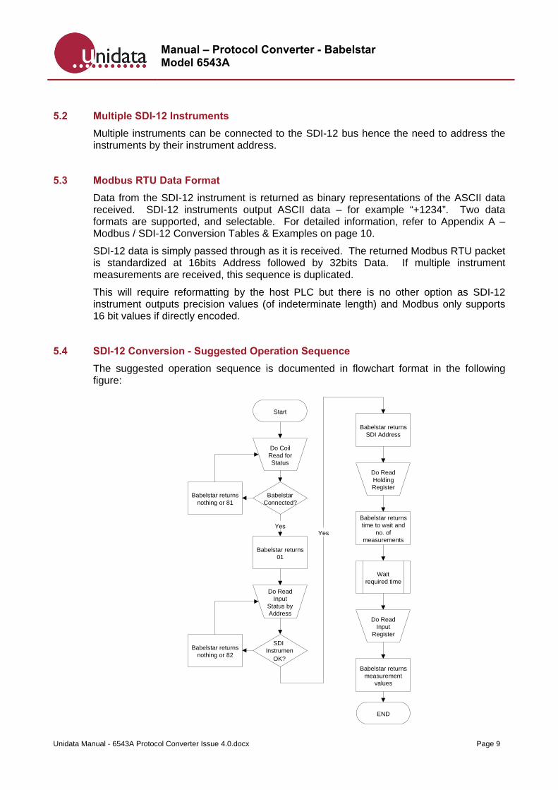
5.4 SDI-12 Conversion - Suggested Operation Sequence
The suggested operation sequence is documented in flowchart format in the following figure:
Start
BabelstarConnected?
Do CoilRead forStatus
Do ReadInput
Status byAddress
Babelstar returns01
Yes
Babelstar returnsnothing or 81
InstrumenOK?
Babelstar returnsnothing or 82
Babelstar returnsSDI Address
Yes
Do ReadHoldingRegister
Babelstar returnstime to wait and
no. ofmeasurements
Waitrequired time
Do ReadInput
Register
Babelstar returnsmeasurement
values
END
SDI
Manual – Protocol Converter - Babelstar Model 6543A
Unidata Manual - 6543A Protocol Converter Issue 4.0.docx Page 10
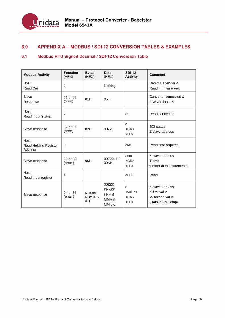
6.0 APPENDIX A – MODBUS / SDI-12 CONVERSION TABLES & EXAMPLES
6.1 Modbus RTU Signed Decimal / SDI-12 Conversion Table
Modbus Activity Function (HEX)
Bytes (HEX)
Data (HEX)
SDI-12 Activity
Comment
Host
Read Coil 1 Nothing
Detect BabelStar &
Read Firmware Ver.
Slave
Response 01 or 81 (error)
01H 05H Converter connected &
F/W version = 5
Host
Read Input Status 2 a! Read connected
Slave response 02 or 82 (error)
02H 00ZZ
a
<CR>
<LF>
SDI status
Z-slave address
Host
Read Holding Register Address
3 aM! Read time required
Slave response 03 or 83 (error )
06H 00ZZ00TT00NN
atttn
<CR>
<LF>
Z-slave address
T-time
-number of measurements
Host
Read Input register 4 aD0! Read
Slave response 04 or 84 (error )
NUMBERBYTES(H)
00ZZK
KKKKK
KKMM
MMMM
MM etc
a
<value>
<CR>
<LF>
Z-slave address
K-first value
M-second value
(Data in 2’s Comp)
Manual – Protocol Converter - Babelstar Model 6543A
Unidata Manual - 6543A Protocol Converter Issue 4.0.docx Page 11
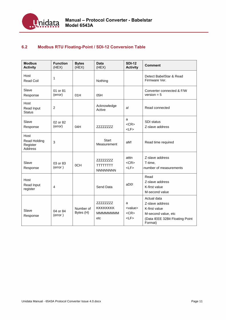
6.2 Modbus RTU Floating-Point / SDI-12 Conversion Table
Modbus Activity
Function (HEX)
Bytes (HEX)
Data (HEX)
SDI-12 Activity
Comment
Host
Read Coil 1
Nothing
Detect BabelStar & Read Firmware Ver.
Slave
Response 01 or 81 (error)
01H
05H
Converter connected & F/W version = 5
Host
Read Input Status
2 Acknowledge Active
a!
Read connected
Slave
Response 02 or 82 (error)
04H
ZZZZZZZZ
a
<CR>
<LF>
SDI status
Z-slave address
Host
Read Holding Register Address
3 Start Measurement
aM! Read time required
Slave
Response
03 or 83 (error )
0CH
ZZZZZZZZ
TTTTTTTT
NNNNNNNN
atttn
<CR>
<LF>
Z-slave address
T-time,
-number of measurements
Host
Read Input register
4
Send Data aD0!
Read
Z-slave address
K-first value
M-second value
Slave
Response
04 or 84 (error )
Number of Bytes (H)
ZZZZZZZZ
KKKKKKKK
MMMMMMMM
etc
a
<value>
<CR>
<LF>
Actual data
Z-slave address
K-first value
M-second value, etc
(Data IEEE 32Bit Floating Point Format)
Manual – Protocol Converter - Babelstar Model 6543A
Unidata Manual - 6543A Protocol Converter Issue 4.0.docx Page 12
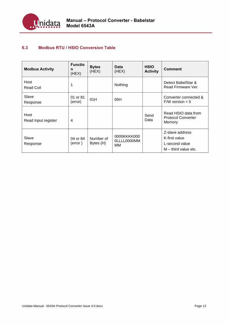
6.3 Modbus RTU / HSIO Conversion Table
Modbus Activity Function (HEX)
Bytes (HEX)
Data (HEX)
HSIO Activity
Comment
Host
Read Coil 1 Nothing
Detect BabelStar & Read Firmware Ver.
Slave
Response 01 or 81 (error)
01H 05H Converter connected & F/W version = 5
Host
Read Input register
4
Send Data
Read HSIO data from Protocol Converter Memory
Slave
Response 04 or 84 (error )
Number of Bytes (H)
0000KKKK0000LLLL0000MMMM
Z-slave address
K-first value
L-second value
M – third value etc.
Manual – Protocol Converter - Babelstar Model 6543A
Unidata Manual - 6543A Protocol Converter Issue 4.0.docx Page 13
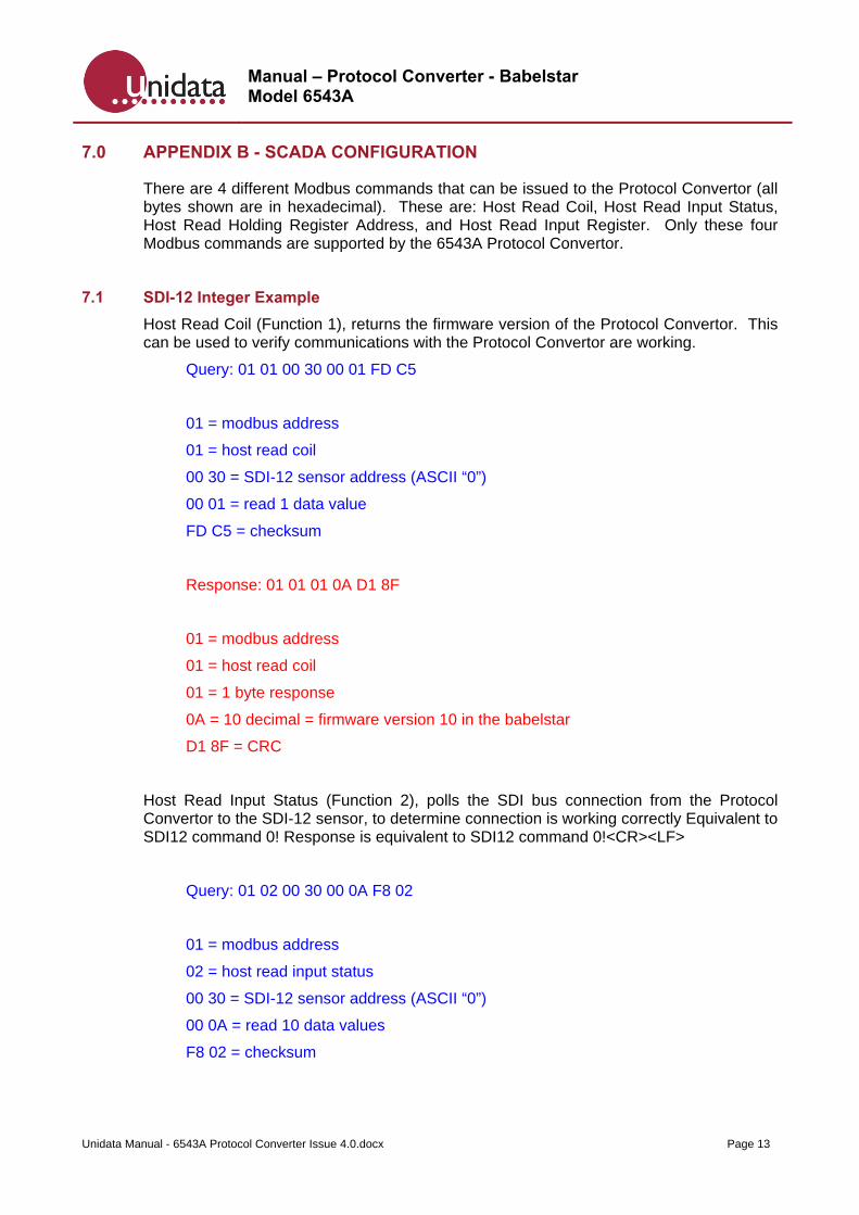
7.0 APPENDIX B - SCADA CONFIGURATION
There are 4 different Modbus commands that can be issued to the Protocol Convertor (all bytes shown are in hexadecimal). These are: Host Read Coil, Host Read Input Status, Host Read Holding Register Address, and Host Read Input Register. Only these four Modbus commands are supported by the 6543A Protocol Convertor.
7.1 SDI-12 Integer Example
Host Read Coil (Function 1), returns the firmware version of the Protocol Convertor. This can be used to verify communications with the Protocol Convertor are working.
Query: 01 01 00 30 00 01 FD C5
01 = modbus address
01 = host read coil
00 30 = SDI-12 sensor address (ASCII “0”)
00 01 = read 1 data value
FD C5 = checksum
Response: 01 01 01 0A D1 8F
01 = modbus address
01 = host read coil
01 = 1 byte response
0A = 10 decimal = firmware version 10 in the babelstar
D1 8F = CRC
Host Read Input Status (Function 2), polls the SDI bus connection from the Protocol Convertor to the SDI-12 sensor, to determine connection is working correctly Equivalent to SDI12 command 0! Response is equivalent to SDI12 command 0!<CR><LF>
Query: 01 02 00 30 00 0A F8 02
01 = modbus address
02 = host read input status
00 30 = SDI-12 sensor address (ASCII “0”)
00 0A = read 10 data values
F8 02 = checksum
Manual – Protocol Converter - Babelstar Model 6543A
Unidata Manual - 6543A Protocol Converter Issue 4.0.docx Page 14
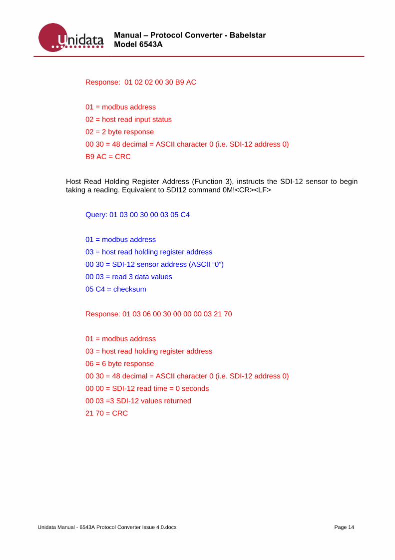
Response: 01 02 02 00 30 B9 AC
01 = modbus address
02 = host read input status
02 = 2 byte response
00 30 = 48 decimal = ASCII character 0 (i.e. SDI-12 address 0)
B9 AC = CRC
Host Read Holding Register Address (Function 3), instructs the SDI-12 sensor to begin taking a reading. Equivalent to SDI12 command 0M!<CR><LF>
Query: 01 03 00 30 00 03 05 C4
01 = modbus address
03 = host read holding register address
00 30 = SDI-12 sensor address (ASCII “0”)
00 03 = read 3 data values
05 C4 = checksum
Response: 01 03 06 00 30 00 00 00 03 21 70
01 = modbus address
03 = host read holding register address
06 = 6 byte response
00 30 = 48 decimal = ASCII character 0 (i.e. SDI-12 address 0)
00 00 = SDI-12 read time = 0 seconds
00 03 =3 SDI-12 values returned
21 70 = CRC
Manual – Protocol Converter - Babelstar Model 6543A
Unidata Manual - 6543A Protocol Converter Issue 4.0.docx Page 15
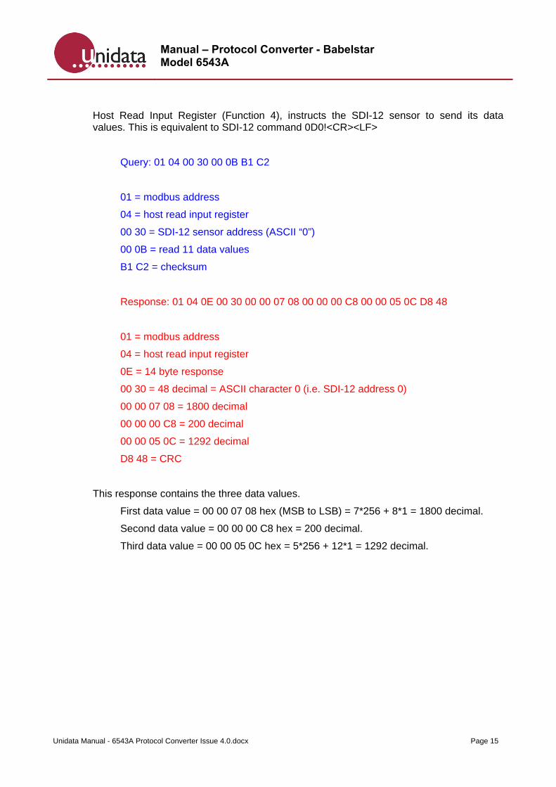
Host Read Input Register (Function 4), instructs the SDI-12 sensor to send its data values. This is equivalent to SDI-12 command 0D0!<CR><LF>
Query: 01 04 00 30 00 0B B1 C2
01 = modbus address
04 = host read input register
00 30 = SDI-12 sensor address (ASCII “0”)
00 0B = read 11 data values
B1 C2 = checksum
Response: 01 04 0E 00 30 00 00 07 08 00 00 00 C8 00 00 05 0C D8 48
01 = modbus address
04 = host read input register
0E = 14 byte response
00 30 = 48 decimal = ASCII character 0 (i.e. SDI-12 address 0)
00 00 07 08 = 1800 decimal
00 00 00 C8 = 200 decimal
00 00 05 0C = 1292 decimal
D8 48 = CRC
This response contains the three data values.
First data value = 00 00 07 08 hex (MSB to LSB) = 7*256 + 8*1 = 1800 decimal.
Second data value = 00 00 00 C8 hex = 200 decimal.
Third data value = 00 00 05 0C hex = 5*256 + 12*1 = 1292 decimal.
Manual – Protocol Converter - Babelstar Model 6543A
Unidata Manual - 6543A Protocol Converter Issue 4.0.docx Page 16
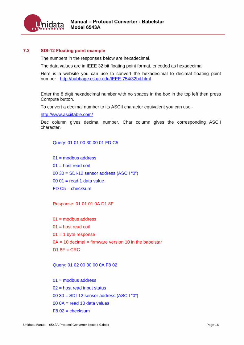
7.2 SDI-12 Floating point example
The numbers in the responses below are hexadecimal.
The data values are in IEEE 32 bit floating point format, encoded as hexadecimal
Here is a website you can use to convert the hexadecimal to decimal floating point number - http://babbage.cs.qc.edu/IEEE-754/32bit.html
Enter the 8 digit hexadecimal number with no spaces in the box in the top left then press Compute button.
To convert a decimal number to its ASCII character equivalent you can use -
http://www.asciitable.com/
Dec column gives decimal number, Char column gives the corresponding ASCII character.
Query: 01 01 00 30 00 01 FD C5
01 = modbus address
01 = host read coil
00 30 = SDI-12 sensor address (ASCII “0”)
00 01 = read 1 data value
FD C5 = checksum
Response: 01 01 01 0A D1 8F
01 = modbus address
01 = host read coil
01 = 1 byte response
0A = 10 decimal = firmware version 10 in the babelstar
D1 8F = CRC
Query: 01 02 00 30 00 0A F8 02
01 = modbus address
02 = host read input status
00 30 = SDI-12 sensor address (ASCII “0”)
00 0A = read 10 data values
F8 02 = checksum
Manual – Protocol Converter - Babelstar Model 6543A
Unidata Manual - 6543A Protocol Converter Issue 4.0.docx Page 17
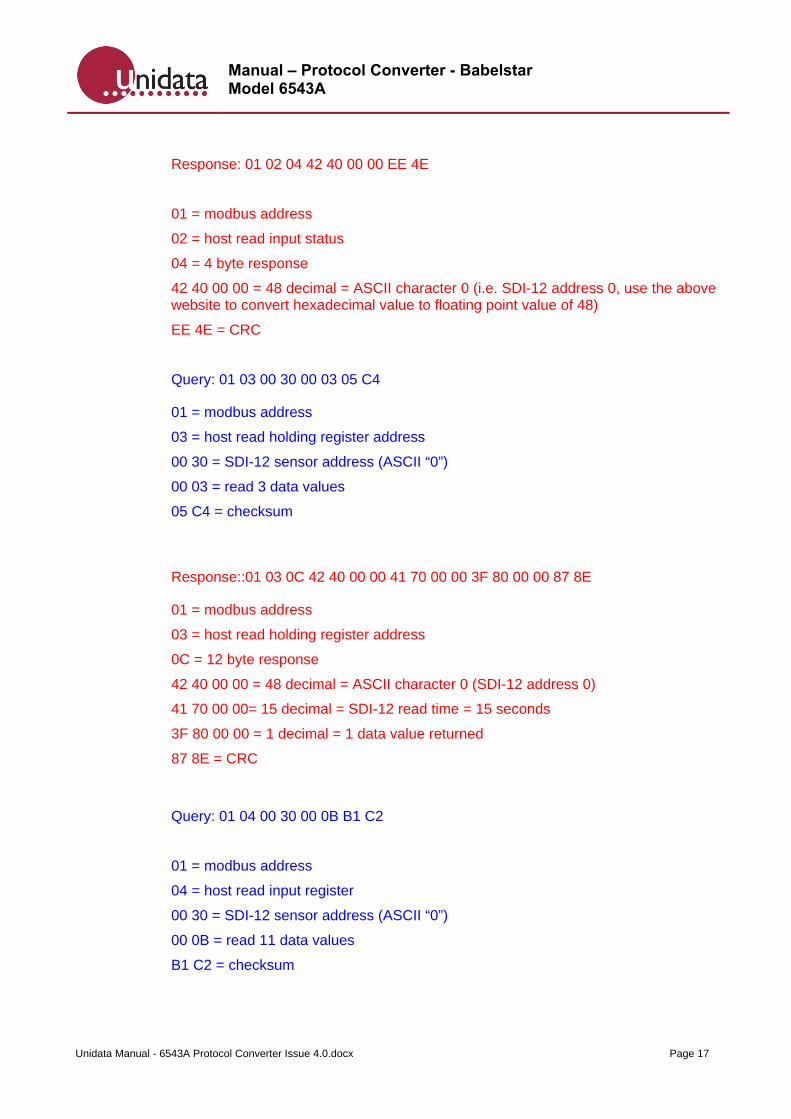
Response: 01 02 04 42 40 00 00 EE 4E
01 = modbus address
02 = host read input status
04 = 4 byte response
42 40 00 00 = 48 decimal = ASCII character 0 (i.e. SDI-12 address 0, use the above website to convert hexadecimal value to floating point value of 48)
EE 4E = CRC
Query: 01 03 00 30 00 03 05 C4
01 = modbus address
03 = host read holding register address
00 30 = SDI-12 sensor address (ASCII “0”)
00 03 = read 3 data values
05 C4 = checksum
Response::01 03 0C 42 40 00 00 41 70 00 00 3F 80 00 00 87 8E
01 = modbus address
03 = host read holding register address
0C = 12 byte response
42 40 00 00 = 48 decimal = ASCII character 0 (SDI-12 address 0)
41 70 00 00= 15 decimal = SDI-12 read time = 15 seconds
3F 80 00 00 = 1 decimal = 1 data value returned
87 8E = CRC
Query: 01 04 00 30 00 0B B1 C2
01 = modbus address
04 = host read input register
00 30 = SDI-12 sensor address (ASCII “0”)
00 0B = read 11 data values
B1 C2 = checksum
Manual – Protocol Converter - Babelstar Model 6543A
Unidata Manual - 6543A Protocol Converter Issue 4.0.docx Page 18
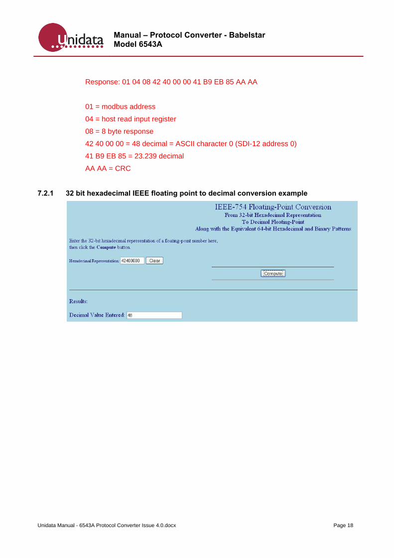
Response: 01 04 08 42 40 00 00 41 B9 EB 85 AA AA
01 = modbus address
04 = host read input register
08 = 8 byte response
42 40 00 00 = 48 decimal = ASCII character 0 (SDI-12 address 0)
41 B9 EB 85 = 23.239 decimal
AA AA = CRC
7.2.1 32 bit hexadecimal IEEE floating point to decimal conversion example
Manual – Protocol Converter - Babelstar Model 6543A
Unidata Manual - 6543A Protocol Converter Issue 4.0.docx Page 19
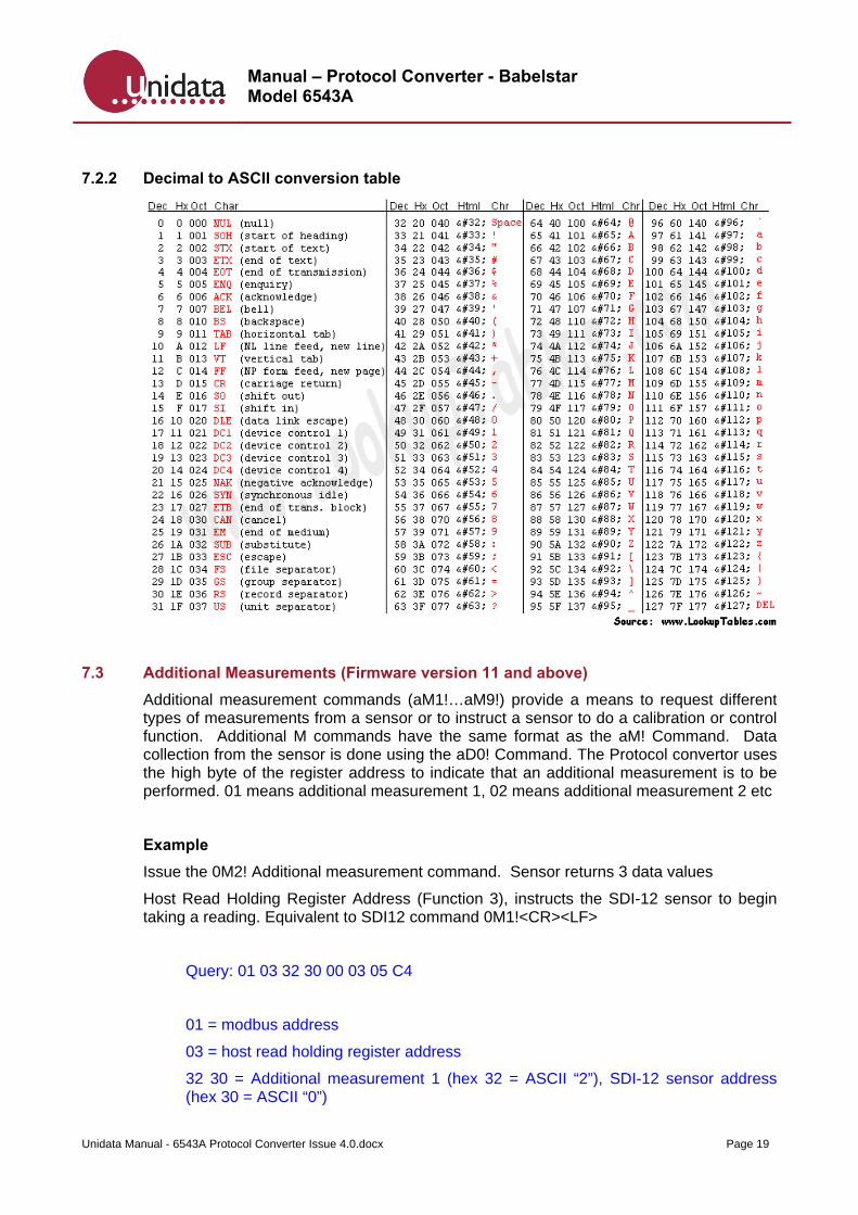
7.2.2 Decimal to ASCII conversion table
7.3 Additional Measurements (Firmware version 11 and above)
Additional measurement commands (aM1!…aM9!) provide a means to request different types of measurements from a sensor or to instruct a sensor to do a calibration or control function. Additional M commands have the same format as the aM! Command. Data collection from the sensor is done using the aD0! Command. The Protocol convertor uses the high byte of the register address to indicate that an additional measurement is to be performed. 01 means additional measurement 1, 02 means additional measurement 2 etc
Example
Issue the 0M2! Additional measurement command. Sensor returns 3 data values
Host Read Holding Register Address (Function 3), instructs the SDI-12 sensor to begin taking a reading. Equivalent to SDI12 command 0M1!<CR><LF>
Query: 01 03 32 30 00 03 05 C4
01 = modbus address
03 = host read holding register address
32 30 = Additional measurement 1 (hex 32 = ASCII “2”), SDI-12 sensor address (hex 30 = ASCII “0”)
Manual – Protocol Converter - Babelstar Model 6543A
Unidata Manual - 6543A Protocol Converter Issue 4.0.docx Page 20
00 03 = read 3 data values
05 C4 = checksum
Response: 01 03 06 00 30 00 00 00 03 21 70
01 = modbus address
03 = host read holding register address
06 = 6 byte response
00 30 = 48 decimal = ASCII character 0 (i.e. SDI-12 address 0)
00 00 = SDI-12 read time = 0 seconds
00 03 =3 SDI-12 values returned
21 70 = CRC
Host Read Input Register (Function 4), instructs the SDI-12 sensor to send its data values. This is equivalent to SDI-12 command 0D0!<CR><LF>
Query: 01 04 00 30 00 0B B1 C2
01 = modbus address
04 = host read input register
00 30 = SDI-12 sensor address (ASCII “0”)
00 0B = read 11 data values
B1 C2 = checksum
Response: 01 04 0E 00 30 00 00 07 08 00 00 00 C8 00 00 05 0C D8 48
01 = modbus address
04 = host read input register
0E = 14 byte response
00 30 = 48 decimal = ASCII character 0 (i.e. SDI-12 address 0)
00 00 07 08 = 1800 decimal
00 00 00 C8 = 200 decimal
00 00 05 0C = 1292 decimal
D8 48 = CRC
Manual – Protocol Converter - Babelstar Model 6543A
Unidata Manual - 6543A Protocol Converter Issue 4.0.docx Page 21
This response contains the three data values.
First data value = 00 00 07 08 hex (MSB to LSB) = 7*256 + 8*1 = 1800 decimal.
Second data value = 00 00 00 C8 hex = 200 decimal.
Third data value = 00 00 05 0C hex = 5*256 + 12*1 = 1292 decimal.
7.4 Return of Multiple Measurements (aD1!...aD9!)
The Protocol convertor does not support the issue of multiple measurements commands. The data values response from the SDI-12 sensor must fit into a single 35 character SDI-12 message. The data can only be retrieved by issuing the aD0! command.