meridian 1 buffer interface/protocol converter
TRANSCRIPT

Meridian 1
Buffer Interface/Protocol Converter Description
Document Number: 553-2801-100Document Release: Standard 5.00Date: April 2000
Year Publish FCC TM
Copyright ©1989–2000 Nortel NetworksAll Rights Reserved
Printed in Canada
Information is subject to change without notice. Nortel Networks reserves the right to make changes in design or components as progress in engineering and manufacturing may warrant. This equipment has been tested and found to comply with the limits for a Class A digital device pursuant to Part 15 of the FCC rules, and the radio interference regulations of Industry Canada. These limits are designed to provide reasonable protection against harmful interference when the equipment is operated in a commercial environment. This equipment generates, uses and can radiate radio frequency energy, and if not installed and used in accordance with the instruction manual, may cause harmful interference to radio communications. Operation of this equipment in a residential area is likely to cause harmful interference in which case the user will be required to correct the interference at their own expense.
SL-1 and Meridian 1 are trademarks of Nortel Networks.
Buffer Interface/Protocol Converter Description


Page 3 of 54
se
64.0
Revision historyApril 2000
Standard 5.00. This is a global document and is up-issued for X11 Relea25.0x.
August 1996Standard 4.00. Reissued for X11 Release 22.0x.
December 1994Standard 3.00. Reissued to include editorial changes and indexing.
December 1991Standard 2.00. This document is reissued to include technical content updates.
December 1989Standard 1.00. Reissued for compliance with Nortel Networks standard 1and to include updates for X11 Release 15.
Buffer Interface/Protocol Converter Description

Page 4 of 54
553-2801-100 Standard 5.00 April 2000

Page 5 of 54
7
8
9
17
18
18
202021
2123
29
29
29
293031
33
Contents
General information . . . . . . . . . . . . . . . . . . . . . . . . 7Reference list . . . . . . . . . . . . . . . . . . . . . . . . . . . . . . . . . . . . . . . . . . . .
Test equipment . . . . . . . . . . . . . . . . . . . . . . . . . . . . . . . . . . . . . . . . . . .
References . . . . . . . . . . . . . . . . . . . . . . . . . . . . . . . . . . . . . . . . . . . . . .
Description . . . . . . . . . . . . . . . . . . . . . . . . . . . . . . . . 11
Interface circuits and protocols . . . . . . . . . . . . . . . 17BIPC protocol requirements . . . . . . . . . . . . . . . . . . . . . . . . . . . . . . . . .
BIPC initialization . . . . . . . . . . . . . . . . . . . . . . . . . . . . . . . . . . . . . . . .
Link control . . . . . . . . . . . . . . . . . . . . . . . . . . . . . . . . . . . . . . . . . . . . .
Message control . . . . . . . . . . . . . . . . . . . . . . . . . . . . . . . . . . . . . . . . . . Message envelopes . . . . . . . . . . . . . . . . . . . . . . . . . . . . . . . . . . . . . Message protocol and responses . . . . . . . . . . . . . . . . . . . . . . . . . . . Message priorities . . . . . . . . . . . . . . . . . . . . . . . . . . . . . . . . . . . . . . Examples . . . . . . . . . . . . . . . . . . . . . . . . . . . . . . . . . . . . . . . . . . . . .
Installation . . . . . . . . . . . . . . . . . . . . . . . . . . . . . . . . 29Reference list . . . . . . . . . . . . . . . . . . . . . . . . . . . . . . . . . . . . . . . . . . . .
Mounting location . . . . . . . . . . . . . . . . . . . . . . . . . . . . . . . . . . . . . . . .
Unpacking and inspection . . . . . . . . . . . . . . . . . . . . . . . . . . . . . . . . . .
Option settings . . . . . . . . . . . . . . . . . . . . . . . . . . . . . . . . . . . . . . . . . . . SDI options . . . . . . . . . . . . . . . . . . . . . . . . . . . . . . . . . . . . . . . . . . . BIPC options . . . . . . . . . . . . . . . . . . . . . . . . . . . . . . . . . . . . . . . . . .
Cable connections . . . . . . . . . . . . . . . . . . . . . . . . . . . . . . . . . . . . . . . .
Buffer Interface/Protocol Converter Description

Page 6 of 54 Contents
33
34
41
41
41
454545
464646
46
Operational checks . . . . . . . . . . . . . . . . . . . . . . . . . . . . . . . . . . . . . . . .
Summary . . . . . . . . . . . . . . . . . . . . . . . . . . . . . . . . . . . . . . . . . . . . . . .
Operating procedures . . . . . . . . . . . . . . . . . . . . . . 41Placing in service . . . . . . . . . . . . . . . . . . . . . . . . . . . . . . . . . . . . . . . . .
Restoring service . . . . . . . . . . . . . . . . . . . . . . . . . . . . . . . . . . . . . . . . .
Repair procedure . . . . . . . . . . . . . . . . . . . . . . . . . . . . . . . . . . . . . . . . .
Ordering information . . . . . . . . . . . . . . . . . . . . . . . 43
Specifications . . . . . . . . . . . . . . . . . . . . . . . . . . . . . 45Mechanical . . . . . . . . . . . . . . . . . . . . . . . . . . . . . . . . . . . . . . . . . . . . . .
BIPC (A0297075) . . . . . . . . . . . . . . . . . . . . . . . . . . . . . . . . . . . Power Supply (A0297998) . . . . . . . . . . . . . . . . . . . . . . . . . . . . .
Electrical . . . . . . . . . . . . . . . . . . . . . . . . . . . . . . . . . . . . . . . . . . . . . . . BIPC (A0297075) . . . . . . . . . . . . . . . . . . . . . . . . . . . . . . . . . . . Power Supply (A0297998) . . . . . . . . . . . . . . . . . . . . . . . . . . . . .
RS-232-C interface . . . . . . . . . . . . . . . . . . . . . . . . . . . . . . . . . . . . . . .
List of terms . . . . . . . . . . . . . . . . . . . . . . . . . . . . . . 49
Index . . . . . . . . . . . . . . . . . . . . . . . . . . . . . . . . . . . . 51
553-2801-100 Standard 5.00 April 2000

Page 7 of 54
10
res,
n, ry.
l
for
tem
General informationReference list
The following are the references in this section:
• Background Terminal Facility Description (553-2311-316)
• X11 Features and Services (553-3001-306)
• X11 Administration (553-3001-311)
This document contains descriptions, installation and operating proceduordering information, and specifications for the Buffer Interface/Protocol Converter (BIPC).
Before starting the Buffer Interface/Protocol Converter (BIPC) installatiocoordination with LODGISTIX or your In House System (IHS) is necessaThe IBM series 1 hardware and software must be modified as per specifications from LODGISTIX or IHS for PBX Interface. Operating without the correct modifications may cause the Buffer Interface/ProtocoConverter (BIPC) to fail or damage the hardware.
The BIPC provides the necessary interface and communication protocolconnecting a customer-provided Property Management System (PMS) through a Serial Data Interface (SDI) port to the switch. The PMS could consist of a LODGISTIX or In House System (IHS) computer.
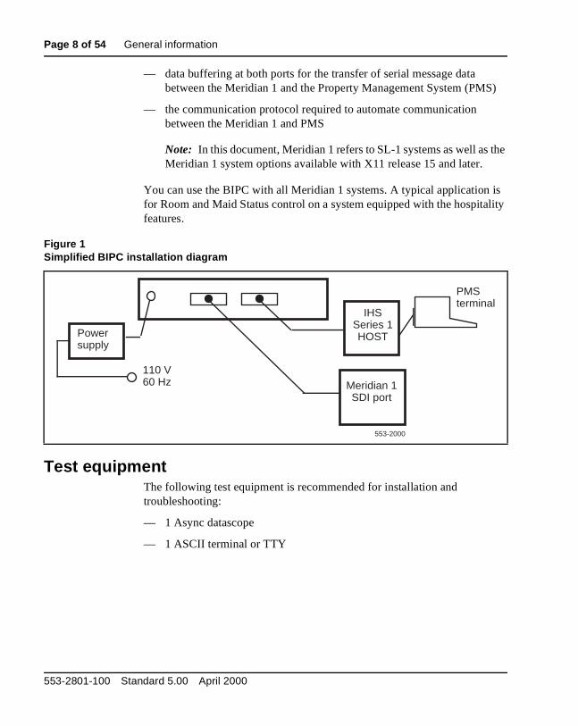
When installed (Figure 1), the BIPC provides
— two bidirectional, RS-232-C ports for connecting to a Serial Data Interface (SDI) port on one side, and the Property Management Sys(PMS) data port on the other side
Buffer Interface/Protocol Converter Description
Page 8 of 54 General information
S)
the
is lity
— data buffering at both ports for the transfer of serial message data between the Meridian 1 and the Property Management System (PM
— the communication protocol required to automate communication between the Meridian 1 and PMS
Note: In this document, Meridian 1 refers to SL-1 systems as well as Meridian 1 system options available with X11 release 15 and later.
You can use the BIPC with all Meridian 1 systems. A typical application for Room and Maid Status control on a system equipped with the hospitafeatures.
Test equipmentThe following test equipment is recommended for installation and troubleshooting:
— 1 Async datascope
— 1 ASCII terminal or TTY
Figure 1Simplified BIPC installation diagram
IHSSeries 1HOST
Meridian 1SDI port
Powersupply
110 V60 Hz
PMSterminal
553-2000
553-2801-100 Standard 5.00 April 2000

General information Page 9 of 54
es:
nt,
ReferencesRefer to the following publications for details concerning hospitality featur
— Background Terminal Facility Description (553-2311-316)
— X11 Features and Services (553-3001-306)
— X11 Administration (553-3001-311)
For details of the standards and specifications referred to in this documeconsult the following documents:
— EIA Standard RS-232-C Interface between Data Terminal Equipment (DTE) and Data Communication Equipment (DCE) employing serial binary data interchange
— CCITT Recommendation V.24 List of definitions for interchange circuits between Data Terminal Equipment (DTE) and Data Circuit-terminating Equipment (DCT)
— ISO Standard 2110-1980 Data Communication, 25-pin DTE/DCE interface connector and pin assignments
Note: EIA RS-232-C and CCITT V.24 are equivalent standards.
Buffer Interface/Protocol Converter Description

Page 10 of 54 General information
553-2801-100 Standard 5.00 April 2000

Page 11 of 54
16
ly.
ed A and
top
ire back sis
DescriptionThe BIPC is a single unit in a metal housing with an external power suppThe overall dimensions of the unit are approximately 14 x 2.5 x 7 in. (356 x 64 x 178 mm).
The front panel of the BIPC has the following characteristics:
— two LEDs, labeled PORT A and PORT B, to indicate when data is received into the applicable interface port of the BIPC
— one LED to indicate when power is applied to the BIPC
— a RESET push-button switch for initializing the BIPC operation
Two 25-pin female connectors are mounted on the back panel and labeland B. These are the RS-232-C interface connectors for the Meridian 1 PMS connections.
The top cover of the unit is secured with four screws. You can remove thecover to access the option switches and jumpers, and other componentsmounted within the unit. Figure 2 shows the layout of the components.
Power for the BIPC is connected from an external power supply. The 5-wcable from the power supply is connected to the power connector at the right corner of the BIPC. It provides + 5, + 12, –12 V dc, ground and chasground connections.
Buffer Interface/Protocol Converter Description

Page 12 of 54 Description
m).
,
in
n s, or is
for ions aces
T
ible ks
ted ion.
rity.
The power supply dimensions are 4.75 x 2.75 x 2.25 in. (121 x 70 x 57 mSee Figure 3. The unit is equipped with the following two power cables:
— a 3-wire, input power cord approximately 6 ft (1.8 m) long, with a standard, UL/CSA approved plug for connection to a standard 3-pin110 V, 60 Hz, AC power outlet
— a 5-wire output power cable, approximately 7 ft (2.1 m) long, with strarelief and a connector for connection between the power supply andthe BIPC
Note: RS-232-C cables to interface to and from the BIPC are not included and must be supplied locally.
The BIPC provides the interface between a Meridian 1 and a PMS. It caoperate at different data rates, use different data handling characteristichave similarly incompatible serial data interface (SDI) circuits. The BIPCfactory set for 9600 baud.
The RS-232-C interfaces between the circuits and the buffering needed the interchange of serial data between the two data terminals. The functand protocols automate the transfer of messages across the BIPC interfand the data links between the data terminals.
All BIPC functions are controlled by a Z80 microprocessor. Operating system storage is provided by an EPROM device (Figure 2). BIPC initialization occurs when power is applied to the unit, or when the RESEswitch on the front panel is pressed.
The two 25-pin female connectors (DB25S), labeled A and B, are compatwith ISO Standard 2110-1980 for pin configuration and numbering. Theyprovide the physical (electrical/mechanical) interface ports for the data linto the Meridian 1 and PMS. The connectors, and the RS-232-C circuits provided on them, are illustrated in Figure 4. The two ports can be operaat independent data rates up to 9600 baud. However, 9600 baud on theMeridian 1 port and 1200 baud on the PMS port are used in this applicatThe word format (code structure and buffer control) of the PMS port is selectable, but the port is hardwired for 8-bit data, one stop bit and no paData buffering to facilitate transfer of data between the independently operated ports is provided by 2 K of RAM (Figure 2).
553-2801-100 Standard 5.00 April 2000

Description Page 13 of 54
Figure 2BIPC component layout diagram
PG
ND
GN
D+
5-1
2N
C+
12
W3
W8
W13
W16
W14
W15
W12
W11
W10
W29
W9
W6
W5
W7
W28 W
27
W22
W21
W30
W4
A (J2)
B (J1)
TC
RC
CT
SD
TR
EX
T
INT
EX
T
INT
CN
T
ON
CN
T
ON
TC
RC
CT
SD
TR
EX
T
INT
EX
T
INT
CN
T
ON
CN
T
ON
9600
4800
2400
1800
1200 60
030
015
013
45 110
W2
W1
AB
Bau
dra
tege
n
XT
AL
Z-8
0
Tim
erB
oard
1K1K
2716EPROM
SW
1
W31
W26
W25
W24
W23
W20
W19
W18
W17
Por
t AP
ort B
RS
TP
ower
553-
2001
Buffer Interface/Protocol Converter Description

Page 14 of 54 Description
For
are pins e 5).
Both BIPC ports are wired to represent data terminal equipment (DTE). normal connections to the data communications equipment (DCE) at theMeridian 1 and the PMS, RS-232-C cables fitted with 25-pin connectorsrequired. The cables must include straight-through connections between1, 2, 3, 7, and 20 on the two connectors to provide RS-232-C interchangcircuits AA, AB, BA, BB, and CD between the BIPC and the DCE (Figure
Figure 3Power supply (A0297998)
Top view
4.75 in.(121 mm)
6-pinSeries 2139Molex Connector
Power output cord7 ft. (2.1 m)
Power input cord6 ft. (1.8 m)
To 110 V60 Hz
End view
2.75 in.(70 mm)
2.25 in(57 mm)
553-2002
553-2801-100 Standard 5.00 April 2000

Description Page 15 of 54
cols ta
e link IPC
ed
arity itch
rms
are
The BIPC provides the necessary conversions between the different protoused by the two data ports to control the flow of serial data across the dalinks. In addition to logic for independent control of the physical links between the BIPC and the two data terminals, the BIPC also provides message handling protocol between the PMS and the BIPC. Because thfrom the SDI port does not use message handling protocol as such, the Badds the required protocol characters to messages originating from the Meridian 1, and conversely strips the control protocol from PMS-originatmessages before transferring the message body to the Meridian 1.
The BIPC also provides error control functions as part of the message handling. Since the SDI ports do not use parity checks, the BIPC adds pbits to the serial data sent to the PMS if parity is enabled on the option sw(SW1). It also detects parity bits in the data stream from the PMS, perfoBlock Character Checks (BCC) for error detection and then removes theparity bits before sending the message body to the Meridian 1. If errors detected, the BIPC initiates error recovery procedures.
Figure 4BIPC interface connectors and interchange circuits
Signal ground
7
RD TD
Frame ground
DTR
3 2 1
20553-2003
Buffer Interface/Protocol Converter Description

Page 16 of 54 Description
553-2801-100 Standard 5.00 April 2000

Page 17 of 54
28
ross
ges, pt
MS
llows:
e of
y
Interface circuits and protocolsBIPC protocol requirements
The BIPC provides the following capabilities:
— transmits messages originated by either the Meridian 1 or the PMS acthe BIPC interface
— overrides PMS originated messages by Meridian 1-originated messaif the messages are originated simultaneously. Messages are interrudriven on the Meridian 1 side and protocol driven on the PMS side.
— does not reformat the message body
— uses asynchronous, RS-232-C data handling at up to 9600 baud
— adds one parity bit to each Meridian 1-generated 8-bit data byte
— strips parity bits from the PMS generated data stream
— uses message control (message envelope) characters at the BIPC/Pinterface as defined in Table 1
— uses interchange protocol, message envelope, and responses at theBIPC/PMS interface as described later
The protocols used between the two data terminals can be classed as fo
— Link Control to handle the establishment, take down, and maintenancthe data links, and the flow of serial data across the links
— Message Control to handle the exchange of the actual message bodacross the BIPC interfaces between the two terminals
Buffer Interface/Protocol Converter Description

Page 18 of 54 Interface circuits and protocols
is aits
C acter ve. the he
n 1 5).
orts
. A
BIPC initializationThe BIPC is initialized when power is applied, or when the RESET buttonpressed. The BIPC sends a carriage return <CR> to the Meridian 1 and wuntil it responds with the period ( . ) prompt character (hex 2E). The BIPdumps any characters received before the prompt. When the prompt charis received, a flag is set in the BIPC indicating that the Meridian 1 is actiWhen an Enquiry (ENQ) is received from the PMS, the flag is checked. If flag is set, the BIPC responds to the PMS with Acknowledged (ACK). If tflag is not set, the BIPC responds with Not Acknowledged (NAK).
Link controlThe data interchange between the BIPC and the two data ports (Meridiaand PMS) is on data links using RS-232-C link control functions (Figure
The RS-232-C interchange circuits required at each of the two interface pappear in Figure 5. The figure includes RS-232-C, CCITT V.24, and Meridian 1 SDI circuit designations for cross-referencing and to show the functions of the circuits in BIPC operation. For more details on the interchange circuits, refer to the applicable standard (RS-232-C or CCITT V.24).
The Specifications section of this document summarizes the electrical characteristics of the interface circuits for Meridian 1/PMS applications.
Several options provide logical control of the data links. You select the options independently by changing the jumpers on the ports (Figure 14)PC board layout drawing is necessary for changing the jumpers.
553-2801-100 Standard 5.00 April 2000

Interface circuits and protocols Page 19 of 54
Figure 5BIPC interface connections and functions
20
25
1234567
TR
1234567
TR
20
25
DTRDTR (CD) 108
Sys. GRD (AB) 102
GRD (AA) 101
IHS interfaceport (DCE)
BIPC(DTE)
RS232C CCITT
J2(Port B)
J1(Port A)
20
25
1234567
1234567
20
25
GRD (AA) 101TD (BA) 103RD (BB) 104
88
Sys. GRD (AB) 102
DTR (CD) 108
RS232C CCITT
Meridian 1 SDI (DCE)
553-2004
Buffer Interface/Protocol Converter Description

Page 20 of 54 Interface circuits and protocols
on
rd he rd
ven
MS ach ter. es
ol.
is
s on
The following options are available:
— Data Terminal Ready (DTR) (on connector pin 20) is strapped continuously on.
— Block Character Checks (BCC) is either on or off. With PMS, this optiis set on by the factory and is set off only if the PMS cannot use or generate BCC error control.
— Word format Port A (to the Meridian 1) is always configured for a woformat of one start bit, 8 databit, no parity, and 1 stop bit. Port B (to tPMS) word format is switch selectable (switch module SW1). The woformat appears in Figure 6. The BIPC is factory set for 7 data bits, eparity, 1 start bit, and 1 stop bit.
Message controlMessage envelopes
BIPC/PMS link The envelope for messages between the BIPC and the Puses the ASCII-encoded control characters listed in Table 1. In addition, emessage block terminates with a Block Character Checks (BCC) characThe BCC maintains message integrity, and is an Exclusive-OR of all bytfollowing the Start of Text (STX), including the End of Text (ETX). The general message format from the sender follows:
ENQ STX (message body) ETX BCC
BIPC/ Meridian 1 link The Meridian 1 does not support a message protocMessages are simply transmitted into the Meridian 1 when it is ready, asindicated by the prompt character. The input message to the Meridian 1Message <CR>, which it echoes back to the BIPC (echoplex). The terminating <CR> indicates the end of a message. The protocol from theMeridian 1 to the BIPC follows:
Note: The number of message lines sent before the prompt dependthe command and the Meridian 1 software.
CR LF nul nul nul nul nul nul Message Body
CR LF nul nul nul nul nul nul Message Body
CR LF nul nul nul nul nul nul (prompt)
553-2801-100 Standard 5.00 April 2000

Interface circuits and protocols Page 21 of 54
nd ct, ch,
e
es
y
the n
y, K
ond ows
Message protocol and responsesThe BCC follows the End of Text (ETX) character in the transmission, athe receiver immediately performs a verification check. If the BCC is correthe receiver responds with Acknowledged (ACK). If the BCC does not matthe receiver responds with Not Acknowledged (NAK).
The port is always configured for 8 data bits, no parity, and 1 stop bit. ThPMS port word format is switch selectable.
The sender does not transmit a new message until it either receives an Acknowledged (ACK) response to the previous message, or until it makthree attempts (ENQ) to send the message and receive an ACK. If the required ACK is not received after three tries or within a 20-second delafrom the time the ENQ is received, the sender flushes the message.
Message prioritiesA receiver may not interrupt a transmitter in the middle of a message. If PMS is sending to the BIPC, the BIPC waits until it has responded with aACK or Not Acknowledged (NAK) before sending any character. Similarlif the BIPC is sending to the PMS, the PMS waits until it responds with ACor NAK before sending any characters to the BIPC. However, a one-sectime out between characters violates the message specifications and allthe receiver to terminate reception of that message.
Figure 6Word format
Start bit Data bits Parity bit(if any)
Stop bits
553-2005
Buffer Interface/Protocol Converter Description

Page 22 of 54 Interface circuits and protocols
Table 1Message control and special character definitions
Character HEX code Definitions
Control characters
ENQ 05 Enquiry: solicits a response from the other terminal
— from the sender, asking the receiver if it is ready to receive a message
— from the receiver, asking the sender to send or resend a message
STX 02 Start of Text: message body follows
ETX 03 End of Text: end of message body
BCC Block Character Check (optional)
ACK 06 Acknowledge: affirmative response from the receiver to the sender (if BCC is used, ACK also indicates BCC check matches)
NAK 15 Not-Acknowledged: negative response from the receiver to the sender (for example, not ready to receive a message or a block of data received with errors requires retransmission)
Special characters
<CR> 0D carriage return (or equivalent)
lf 0A line feed (or equivalent)
. 2E ASCII character period (prompt character for Meridian 1)
00 00 Null (nu) character
xx represents any hex number
553-2801-100 Standard 5.00 April 2000

Interface circuits and protocols Page 23 of 54
f the in
ExamplesThe examples appearing in Figures 8 through 12 illustrate applications omessage protocols under both normal and error conditions. The diagramFigure 7 illustrates the message channels implied in these examples:
Figure 7BIPC connection diagram with communication channels
Figure 8 Valid transaction example
(message from PMS to Meridian 1)
Figure 9 Invalid format example
(control character in message body from PMS to BIPC)
Figure 10 Transaction with error example
(BCC mismatch in the BIPC to PMS message)
Figure 11 Valid transaction example
(single message from Meridian 1 to PMS)
Figure 12 Valid transaction example
(multiple messages from Meridian 1 to BIPC)
BIPC (DTE) PMS (DCE)
Chan. 2a
Chan. 2b
RCV
TRMT
Meridian 1 (DCE)
Chan. 1a
Chan. 1b
RCV Chan. 1
TRMT Chan. 1
TRMT Chan. 2
RCV Chan. 2
553-2006
TRMT
RCV
Buffer Interface/Protocol Converter Description

Page 24 of 54 Interface circuits and protocols
Figure 8Valid transaction example (message from PMS to Meridian 1)
Meridian 1 SDIBIPCPMS
SL-1 promptACK(Note)
ENQ
STXNo responseBuffer opens
Message body
ETX
BCC
No responseMessage stored
No responseAwaiting BCC
Error checkBCC match
ACK
Message body
CR
Message receivedAll characters echoed
CR received
SL-1 promptReady for next transaction
553-2007
Note: ENQs are NAKs until the BIPC receives a prompt from the Meridian 1.
553-2801-100 Standard 5.00 April 2000

Interface circuits and protocols Page 25 of 54
Figure 9Invalid format example (control character in message body)
PMS BIPC
ENQ (Meridian 1 prompt must be received before ACK is sent.)
ACK
STX (Note)
ETX
BCC
No response
No responseAwaiting BCC
Error check
ACK(if BCC match)
orNAK
(if BCC mismatch)
553-2008
Note: The message can be up to 100 characters. The message body is not sent to the Meridian 1. Control characters are not permitted in the message body.
Buffer Interface/Protocol Converter Description

Page 26 of 54 Interface circuits and protocols
Figure 10Transaction with error (BCC mismatch in the BIPC to PMS message)
PMS BIPC
ENQ
ACK
STX
ETX
BCC
No response
No response / Awaiting BCC
Error check / BCC mismatch
Message body No response
NAK
ENQ
ACK
STX
ETX
BCC
No response
No response / Awaiting BCC
Error check / BCC mismatch
Message body No response
NAK
ENQ
ACK
STX
ETX
BCC
No response
No response / Awaiting BCC
Error check / BCC mismatch
Message body No response
NAK
BIPC flushes message553-2009
553-2801-100 Standard 5.00 April 2000

Interface circuits and protocols Page 27 of 54
Figure 11Valid Transaction (a single message from Meridian 1 to PMS)
PMSBIPCMeridian 1 SDI
CR LFNo responseBuffer opens
00 00 00 00 00 00 No responseNulls not stored
Message body Message body storedEnd of Meridian 1 message
Meridian 1 prompt
00 00 00 00 00 00 No response
ENQ
ACK
STX
ETX
BCC
No responseAwaiting BCC
Error checkBCC match
Message body
ACKReady for next transaction
553-2010
Buffer Interface/Protocol Converter Description

Page 28 of 54 Interface circuits and protocols
Figure 12Valid Transaction (multiple messages from Meridian 1 to BIPC)
Meridian 1 SDI sends BIPC Response / Action
CR LF 00 00 00 00 00 00
Message body
No responseBuffer opens as CR LF is received
No responseMessage stored
CR LF 00 00 00 00 00 00
Message body
Message body ready to be sent to PMS (see Figure 8)
No responseMessage stored
CR LFMessage body ready to be sent to PMS (see Figure 8)
00 00 00 00 00 00 No response
Meridian 1 prompt
553-2011
553-2801-100 Standard 5.00 April 2000

Page 29 of 54
40
S e a
hin
er
. r an
5.
InstallationReference list
The following are the references in this section:
• Circuit Card Installation and Testing (553-3001-211)
Mounting locationMount the BIPC at any convenient location that meets or exceeds the following requirements:
— The cable length from the BIPC to the Meridian 1 SDI and to the PMmust not exceed 50 ft (15 m). If the distance is greater than 50 ft, usshort-haul modem or a line driver.
— The power supply (Figure 13) must be located so that the BIPC is witreach of the output cable (approximately 7 ft. [2.1 m]). A 110/120 V,60 Hz, 3-pin power receptacle is within reach of the power supply powcord (6 ft. [1.8 m]).
To prepare the BIPC mounting location, clear sufficient space for settingthe BIPC and the power supply on a flat surface approximately 15 x 8 in(381 x 203 mm) for the BIPC and 5.5 x 3 in. (140 x 76 mm) for the powesupply. A recommended location for the BIPC is on the top of the Meridi1 cabinet, with the power supply beside or on top of the BIPC.
Unpacking and inspectionUnpack and inspect the equipment as detailed in Procedure 1 on page 3
Option settingsUse the steps in Procedure 2 on page 35 for selecting the options.
Buffer Interface/Protocol Converter Description

Page 30 of 54 Installation
SDI optionsSet the address and speed switches on the SDI circuit pack. See Circuit Card Installation and Testing (553-3001-211)for the settings for your particular SDI card.
553-2801-100 Standard 5.00 April 2000

Installation Page 31 of 54
14. the (B) er is
Note: The address is determined locally, and can be any number (00 to 15) not previously assigned to another SDI port.
BIPC optionsOption switches and jumpers are located on the BIPC as shown in FigureThe options are on SW1 as seen in Figure 3. Set the jumper on W2 (A) todata rate of the Meridian 1 (9600 bps, for example). Set the jumper on W1to the data rate of the PMS (1200 bps, for example). Be sure that the powoff, and observe the static.
Figure 13BIPC power cabling
BIPC
A B
PowerSupply
6 ft (1.8 m)(maximum)
7 ft (2.1 m)(maximum)
To 110 V60 Hzoutlet
553-2012
Buffer Interface/Protocol Converter Description

Page 32 of 54 Installation
Figure 14BIPC option switches and jumpers
1 2 3 4 5 6 7 8
ON
1 = X11
Generic
1 = Enabled 0 = Disabled
BCC
0 = 501 = 7 10 = 611 = 8
Number ofdata bits
1 = Enabled 0 = Disabled
1 = Even 0 = Odd
Parity
00 = Invalid01 = 1.510 = 1 11 = 2
Number ofstop bits
SW1
553-2014
553-2801-100 Standard 5.00 April 2000

Installation Page 33 of 54
n
the
e
he
cted.
Cable connectionsConnect data and power cables to the BIPC as detailed in Procedure 3 opage 36.
Operational checksAfter the BIPC is installed, perform operational checks to verify that the BIPC is correctly transferring message data between the Meridian 1 andPMS processor in both directions.
The actual operations for the test depend on the feature controlled by thPMS. In general, the procedure should check the following:
— Commands and data from the Meridian 1 are received correctly by tPMS processor.
— Commands and data from the PMS are received correctly by the Meridian 1.
Note: Use a datascope to monitor data transfer if a problem is suspe
Procedure 4 on page 38 illustrates a typical operational exercise using Room Status.
Buffer Interface/Protocol Converter Description

Page 34 of 54 Installation
S
ack.
e nce
r
SummaryTo install the BIPC, follow these steps. Where the step refers to anotherprocedure, go to that procedure for complete instructions.
1 Unpack and inspect the equipment (Procedure 1).
2 Ensure that the required option settings are set on the BIPC. For PMIBM Series 1 computer, or your In House System (IHS), refer to Procedure 2.
3 Clear the BIPC mounting location.
4 Install the BIPC in its operating location.
5 Verify, and set if necessary, the option selections on the SDI circuit p
6 Using RS-232-C cables, connect BIPC Port A to the SDI and BIPC Port B to the PMS data port (Procedure 3).
7 Connect power to the BIPC, and press the RESET button on the faceplate.
8 Check the installation by performing typical operations on the system(Procedure 4).
Note: To verify message transactions between the Meridian 1 and thPMS, it may be necessary to connect a datascope into the circuit. Othe operation is verified, the datascope can be removed.
Before unpacking your BIPC, ensure that the IBM series 1 is modified foPBX interface by LODGISTIX.
553-2801-100 Standard 5.00 April 2000

Installation Page 35 of 54
Procedure 1Unpacking and inspection procedure
1 Open the shipping cartons and remove the equipment carefully. Inspect all items for external evidence of shipping damage. If there is noticeable damage, save the shipping cartons and notify Nortel Networks.
2 Remove the four screws securing the cover on the BIPC, and lift the cover from the unit.
3 Inspect the interior for components that may have loosened or been damaged in shipment (especially the 2716 PROM).
4 Report evidence of damage to Nortel Networks.
Note: If physical installation of the BIPC is to continue at this time, leave the cover off until you verify the option selectors and connect the power cabling. Otherwise, replace the cover on the unit.
Procedure 2BIPC option verification
1 Remove the top cover of the BIPC (may already be removed in Procedure 1).
2 Check the data speeds for Ports A and B. Set Jumpers on options W2 and W1 to the positions marked with the required rates (Figure 14).
Note: Always use Port A for the BIPC/Meridian 1 interface and Port B for the BIPC/PMS interface.
3 Verify the options for Port B (selectors 3 to 8 on switch module SW1).
4 Verify selector 1 on switch module SW1 (ON for Meridian 1 systems).
5 Verify selector 2 on switch module SW1 (ON for BCC).
6 Replace the cover on the BIPC or proceed to Procedure 3.
Buffer Interface/Protocol Converter Description

Page 36 of 54 Installation
rol.
e ted ith
Procedure 3BIPC cable connection
1 Position the BIPC and the power supply at their operating locations (on top of the Meridian 1 cabinet, for example).
2 With the top cover removed from the BIPC, connect the power cable from the power supply to the power connector on the BIPC.
3 Replace the cover on the BIPC.
4 Connect one end of an RS-232-C cable to Port A on the BIPC, and the other to the applicable SDI connector on the SDI card.
5 Connect an RS-232-C cable (the maximum length is 50 ft) between the PMS data port and Port B on the BIPC. If the distance is greater than 50 ft, use a line driver or a short-haul modem.
6 Plug the power supply cord into a 110 V 60 Hz AC outlet.
7 The BIPC can now be placed in service, at any time.
The following procedure presents a typical exercise to verify the correct operation of a BIPC unit in a system set up for Room or Maid Status contBefore installing the BIPC, prepare the Meridian 1 for the interface. The preparation consists of the following steps.
1 The Room Status feature must be assigned to guest room directorynumbers (DNs) (Controlled Class of Service Allowed [CCSA]).
2 Program a background terminal (BGD) capability on an SDI port. ThRoom Status feature can be administered from any terminal designaby a service change as a BGD. Use LD17 to configure the terminal wthe following prompt-response sequence:
• IOTB—YES
• ADAN—NEW/CHG TTY xx
• USER—BGD (Note 1)
• PARM—YES
• NDIS—150 (Note 2)
553-2801-100 Standard 5.00 April 2000

Installation Page 37 of 54
n
the e
us
her ve
m ffic oes
3 Use LD22 and the following prompt-response sequence to verify thesystem configuration update:
• REQ—PRT
• TYPE—CFN
4 Verify that the number of Number of Display Messages (NDIS) showon the printout is 150 or more and that the only user listed on the background terminal is BGD.
5 Connect an ASCII terminal (or TTY) to the background port and set following options. After you set the options, type OP <CR> to verify thsettings.
6 Use the steps in Procedure 4 to test the operation of the Room Statfeature.
Note 1: Only BGD message type should be assigned to this port. If otusers (MTC, SCH, BUG, etc.) are already assigned to the port, remothem before proceeding to the next step.
Note 2: The number of background display messages can range fro0 to 255. To prevent losing Room Status messages during heavy traperiods, NDIS should be set to 150 or higher. If the system memory dnot allow for such an accommodation, assign the maximum numberallowed.
A SE OP DI ON <CR>
SE OP DI ME OF <CR>
SE OP TE OF <CR>
SE OP DI DE OF <CR>
B SE OP PO (Port ID) OFF <CR>
SE OP PO (Port ID) ST ON <CR>
C SE OP CH ON <CR>
D SE OP TI DE OF <CR>
E SE OP TI RE OF <CR>
F SE OP TI DI ON <CR>
G SE OP SA ON <CR>
H SE OP CO OF <CR>
Buffer Interface/Protocol Converter Description

Page 38 of 54 Installation
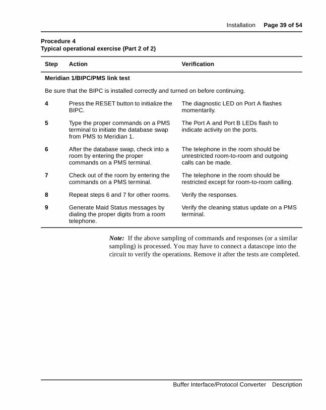
Procedure 4Typical operational exercise (Part 1 of 2)
Step Action Verification
Room Status test
1 Input: SE ST xxxx CH IN <CR>
(Set status of room DN to Check In. xxxx is the room DN)
Try making an outgoing call from telephone xxxx. The system should permit this call type as well as room-to-room dialing.
Input: SE ST xxxx CH OU <CR>
(Set status of room DN to check out)
Try making an outgoing call from telephone xxxx. The system should not permit this call type. However, room-to-room dialing should be possible.
Input: SE ST xxxx CH IN <CR>
(Set status of room DN to check in)
Try making an outgoing call from telephone xxxx. The system should now permit this call type as well as room-to-room dialing.
2 Generate Room Status messages by dialing the proper digits from the guest room telephone.
Verify the status update, which should display automatically on the terminal.
3 If the above test is successful, use LD43 to perform a data dump.
553-2801-100 Standard 5.00 April 2000
Installation Page 39 of 54
lar the ed.
Note: If the above sampling of commands and responses (or a simisampling) is processed. You may have to connect a datascope into circuit to verify the operations. Remove it after the tests are complet
Meridian 1/BIPC/PMS link test
Be sure that the BIPC is installed correctly and turned on before continuing.
4 Press the RESET button to initialize the BIPC.
The diagnostic LED on Port A flashes momentarily.
5 Type the proper commands on a PMS terminal to initiate the database swap from PMS to Meridian 1.
The Port A and Port B LEDs flash to indicate activity on the ports.
6 After the database swap, check into a room by entering the proper commands on a PMS terminal.
The telephone in the room should be unrestricted room-to-room and outgoing calls can be made.
7 Check out of the room by entering the commands on a PMS terminal.
The telephone in the room should be restricted except for room-to-room calling.
8 Repeat steps 6 and 7 for other rooms. Verify the responses.
9 Generate Maid Status messages by dialing the proper digits from a room telephone.
Verify the cleaning status update on a PMS terminal.
Procedure 4Typical operational exercise (Part 2 of 2)
Step Action Verification
Buffer Interface/Protocol Converter Description

Page 40 of 54 Installation
553-2801-100 Standard 5.00 April 2000

Page 41 of 54
42
ly.
1.
C y ure
lace o,
Operating proceduresPlacing in service
Follow these steps to place the BIPC in service:
1 Verify that the BIPC is installed correctly, that Meridian 1 data fill is completed, and that all data and power cables are connected secure
2 Plug in the power supply. (The red power indicator lights.)
3 Press the BIPC RESET button. This sends a <CR> to the Meridian
The BIPC is now ready. No further adjustment is required for normal operation.
Restoring serviceIf, for any reason, service through the BIPC is interrupted, restart the BIPby pressing the RESET switch. However, if the BIPC itself is faulty, it mabe necessary to replace the unit. Additionally, check the SDI port to be sthat it is set and operating properly.
Repair procedureThe BIPC has no field replaceable parts other than the power supply. Repa faulty BIPC with a working unit to ensure continued operation. To do sfollow the replacement procedures for defective Meridian 1 units.
Buffer Interface/Protocol Converter Description

Page 42 of 54 Operating procedures
553-2801-100 Standard 5.00 April 2000

Page 43 of 54
44
Ordering informationBIPC equipment can be ordered from Nortel Networks by quoting the applicable ordering codes and quantities required as follows:
Equipment Ordering Code Quantity Required
BIPC A0297075 One per PMS/Meridian 1 Interface (includes one power supply)
Power Supply A0297998 One per BIPC
Buffer Interface/Protocol Converter Description

Page 44 of 54 Ordering information
553-2801-100 Standard 5.00 April 2000

Page 45 of 54
48
ows:
SpecificationsMechanical
BIPC mechanical specifications and associated hardware appear as foll
BIPC (A0297075)
Power Supply (A0297998)
Size Width: 14 in. (356 mm)
Height: 2.5 in. (64 mm)
Depth: 7 in. (178 mm)
Weight 2.5 lbs (1.6 kg)
Enclosure all metal
Size Length: 4.75 in. (121 mm)
Width: 2.75 in. (70 mm)
Height: 2.25 in. (57 mm)
Cables Input: 6 ft (1.8 m), 3-wire, fitted with a UL/CSA approved 3-pin plug
Output: 7 ft (2.1 m), 5-wire (18 AWG) with strain relief
Buffer Interface/Protocol Converter Description

Page 46 of 54 Specifications
ows:
tics
ElectricalBIPC Electrical specifications and associated equipment appears as foll
BIPC (A0297075)
Power Supply (A0297998)
RS-232-C interfaceThe following is a summary of the mechanical and electrical characterisof the interface between the BIPC and an SDI port:
— Electrical interface: Compatible with EIA Standard RS-232-C
— Operating mode: Full duplex, asynchronous
— Signal logic levels:
• Space or ON = more positive than + 3 V (binary 0)
• Mark or OFF = more negative than –3 V (binary 1)
— ASCII character set
— No parity (parity disabled)
— Word framing: 10 bits consisting of the following:
• 1 START bit
• 8 DATA bits (Bit 8 is always tied to high)
• 1 STOP bit
Power requirement + 5 V dc, 800 mA
+ 12 V dc, 100 mA
–12 V dc, 100 mA
Input power 105 to 129 V ac, 57 to 60 Hz
Output power + 5 V dc ±5% at 1.0 A
+ 12 V dc ±5% at 0.2 A
–12 V dc ±5% at 0.2 A
Ripple and noise ð 10 mV ms on all outputs
Regulation ð ±5% on all outputs
UL and CSA approved
553-2801-100 Standard 5.00 April 2000

Specifications Page 47 of 54
on)
eam
ics
— No message control (logical) protocol (that is, no ENQ, ACK, and so
— No data record frame characters
— The SDI port connector is female
— The SDI data port addresses are 00 to 15
— The prompt character is a period (hex 2E)
— The character sequence indicating that a Meridian 1 initiated data stris as follows:
0DH 0AH 00H 00H 00H 00H 00H 00H (CR LF nul nul nul nul nul)
The following is a summary of the mechanical and electrical characteristof the interface between the BIPC and a PMS port:
— Electrical interface: Compatible with EIA Standard RS-232-C
— Operating mode: Full duplex, asynchronous
— Signal logic levels:
• Space or ON = more positive than + 3 V (high)
• Mark or OFF = more negative than –3 V (low)
— Signal form: Compatible with EIA Standard RS404
— Data rate: 110, 134, 150, 300, 600, 1200, 1800, 2400, 3600, 4800, 7200, or 9600, selectable
— Parity: Odd or even (or no parity), selectable
— Word framing:
• 1 START bit
• 5, 6, 7, or 8 DATA bits (selectable)
• 1 PARITY bit
• 1, 1-1/2, or 2 STOP bits (selectable)
— Maximum message text: 100 bytes
— The PMS port connector is female
Buffer Interface/Protocol Converter Description

Page 48 of 54 Specifications
553-2801-100 Standard 5.00 April 2000

Page 49 of 54
50
CC
s
ves ntrol
. For h
List of termsACK
Acknowledge or affirmative response from the receiver to the sender. If Bis used, ACK also indicates BCC check matches.
BCC Block Character Checks.
BIPC Buffer Interface/Protocol Converter.
DCE Data Communication Equipment. The interfacing equipment that couplefrom a data terminal into a transmission circuit or channel, and from a transmission circuit or channel into a data terminal.
DTE Data Terminating Equipment. The functional unit of a data station that seras a data source or data sink and provides for the data communication cofunction to be performed in accordance with link protocol.
DTR Data Terminal Ready.
NAK Not Acknowledged or a negative response from the receiver to the senderexample, not ready to receive a message or a block of data received witerrors, requires retransmission.
PMS Property Management System.
SDI Serial Data Interface.
Buffer Interface/Protocol Converter Description

Page 50 of 54 List of terms
553-2801-100 Standard 5.00 April 2000

Page 51 of 54
54
Index
AACK/NAK responsesBIPC initialization, 18message priorities, 21message protocol, 21
Bbaud rates
RS-232-C interface, 12setting, 31
BCC (Block Character Checks)as error control function, 15described, 20mismatch, 26setting on/off, 20, 32
BIPC (Buffer Interface/Protocol Converter)communication channel connections, 23description, 11installation block diagram, 8installing, 29interface circuits/protocols, 17operating procedures, 41ordering equipment, 43overview, 7setting options, 31specifications, 45
BIPC/ Meridian 1 link, 20BIPC/PMS link, 20buffer, size of data, 12
Ccables
connecting, 33, 36maximum length, 29power, 12, 31, 45See also RS-232-C cables/connectors
capabilities, BIPC, 17CCITT V.24 standard, 18characters. See BCC (Block Character Checks);
control characters; special character definitions
communication channel connections, 23component layout (circuit card), 13connectors
external, 12pin assignments, 19See also RS-232-C cables/connectors
control characters, 22
Ddata links, logical control options for, 18data rates. See baud ratesdimensions, physical, 11, 45documentation, reference, 9DTR (Data Terminal Ready) signal
continuously-on option, 20
Eelectrical specifications, 46error control functions, 15errors, BCC mismatch, 26
Buffer Interface/Protocol Converter Description

Page 52 of 54 Index
Gglossary, 49
Hhandshaking. See ACK/NAK responses
Iindicators, front panel, 11initialization, 12, 18inspecting BIPC, 29installing BIPC, 29interface circuits, 17
Jjumpers
changing data link control options, 18setting data rates, 31stop bit settings, 32
LLink Control protocols
overview, 17, 18LODGISTIX, preinstallation coordination with, 7logic levels
PMS port, 47SDI port, 46
MMaid Status feature, verifying operation of, 36, 39mechanical specifications, 45Meridian 1
checking command/data transfer, 33, 39RS-232-C port baud rate, 12
message control protocols, 17, 21message envelopes, 20message handling protocols, 15message priorities, 21messages
invalid format, 25multiple, 28sample transactions, 23
microprocessor, Z80, 12mounting location, BIPC, 29
NNAK. See ACK/NAK responses
Ooperating procedures, 41operational checks
Meridian 1/BIPC/PMS link test, 39overview, 33Room/Maid Status feature, 36
option settingsdescribed, 29switches/jumpers controlling, 32verifying, 35
ordering BIPC equipment, 43
Pparity bits/checks
as error control function, 15option switch settings, 32PMS port, 12, 47SDI port, 46
pin assignments, RS-232-C interfaceSDI through IHS, 19
PMS (Property Management System)checking command/data transfer, 33, 39interfacing to switch, 7RS-232-C port baud rate, 12
Port A (BIPC to Meridian 1)electrical/mechanical specifications, 46word format, 20
Port B (BIPC to PMS)electrical/mechanical specifications, 47word format, 20
power supplycables/connectors, 14described, 11electrical specifications, 46mechanical specifications, 45mounting location, 29
protocol conversion, 15protocol requirements, 17
553-2801-100 Standard 5.00 April 2000

Index Page 53 of 54
Rreference documentation, 9repair procedure, BIPC, 41resetting BIPC, 12, 18, 41restoring service, 41Room Status feature, verifying operation of, 36, 3RS-232-C cables/connectors
external locations, 11pin wiring, 14
RS-232-C interfacebaud rates, 12BIPC interchange circuits, 18described, 12electrical/mechanical specifications, 46
SSDI (Serial Data Interface) port
pin assignments, 19setting address/speed switches, 30
signal logic levels. See logic levelsspecial character definitions, 22specifications, 45stop bits, setting number of, 32
Ttest equipment, recommended, 8
8
tests, operational, 33
Uunpacking BIPC, 29, 35
VV.24. See CCITT V.24 standard
Wword format, 12
diagram, 21jumper settings, 32Port A/B settings, 20
word framingPMS port, 47SDI port, 46
XX11 release 15 and later, 8
ZZ80 microprocessor, 12
Buffer Interface/Protocol Converter Description

Page 54 of 54 Index
553-2801-100 Standard 5.00 April 2000


Family Product Manual Contacts Copyright FCC notice Trademarks Document number Product release Document release Date PublishCopyright
Meridian 1
Buffer Interface/Protocol ConverterDescription
Copyright ©1989–2000 Nortel NetworksAll Rights ReservedInformation is subject to change without notice. Nortel Networks reserves the right to make changes in design or components as progress in engineering and manufacturing may warrant. This equipment has been tested and found to comply with the limits for a Class A digital device pursuant to Part 15 of the FCC rules, and the radio interference regulations of Industry Canada. These limits are designed to provide reasonable protection against harmful interference when the equipment is operated in a commercial environment. This equipment generates, uses and can radiate radio frequency energy, and if not installed and used in accordance with the instruction manual, may cause harmful interference to radio communications. Operation of this equipment in a residential area is likely to cause harmful interference in which case the user will be required to correct the interference at their own expense.SL-1 and Meridian 1 are trademarks of Nortel Networks.Publication number: 553-2801-100Document release: Standard 5.00Date: April 2000Printed in Canada