manual motor home van exclusive, toskana exclusive and sphinx · from driving this vehicle and help...
TRANSCRIPT

Version 08/2011
Manual Motor home Van Exclusive, Toskana Exclusive and Sphinx
GB
Introduction
Dear Camper,
Congratulations on the purchase of your new HOBBY motor home. The trust you have
placed in us is both an incentive and an obligation to continuously implement new ideas,
technical innovations and fine touches to make our motor homes even better. Our fully fitted
and highly sophisticated models enable us to offer you the perfect setting for the most enjo-
yable days of the year.
Please read this user manual carefully, even if you have already been driving a motor home
for quite some time. This will help to prevent operating errors and damage to the vehicle and
its equipment. Handling all of the technical details correctly will increase the pleasure you get
from driving this vehicle and help to retain the value of your motor home.
If this user manual should be unable to provide the required assistance, a close, pan-Europe-
an network of dealers is available for further help. Take advantage of your authorised dealer's
experience and technical knowledge - we recommend speaking to him in detail before taking
your first trip with your HOBBY motor home.
We wish you and your fellow travellers many enjoyable trips and hope you will always have a
safe journey with your new HOBBY motor home.
Your
HOBBY – Wohnwagenwerk
Ing. Harald Striewski GmbH

Introduction
Chapter 1: Introduction1.1 General information ................................................ 01-11.2 Before taking your first drive .................................. 01-11.3 Designations in the operating instructions ............. 01-2
Chapter 2: Safety2.1 General information ................................................ 02-12.2 Fire protection ........................................................ 02-12.3 Road safety ............................................................ 02-22.4 What to observe before taking your first drive ....... 02-22.5 Before and while driving......................................... 02-32.6 Notes for your journey ........................................... 02-52.7 Vehicle tool kit ........................................................ 02-82.8 Emergency equipment ........................................... 02-92.9 When you stop driving ......................................... 02-10
Chapter 3: Chassis3.1 Chassis .................................................................. 03-13.2 Loading .................................................................. 03-13.3 Leveling supports ................................................... 03-43.4 Entrance step ......................................................... 03-53.5 Vehicle identification number (VIN) ........................ 03-63.6 Additional pneumatic springs ................................ 03-63.7 Towing fixture ......................................................... 03-73.8 Externally mounted fixtures ................................... 03-83.9 Automatic transmission ......................................... 03-8
Chapter 4: Wheels, tyres, brakes4.1 Wheels ................................................................... 04-1
4.2 Tyres ....................................................................... 04-14.3 Tyre pressure .......................................................... 04-24.4 Tread depth ............................................................ 04-24.5 Wheel rims ............................................................. 04-34.6 Spare tire ................................................................ 04-34.7 Tyre repair kit .......................................................... 04-44.8 Brakes .................................................................... 04-8
Chapter 5: Exterior Structure5.1 Overview of tank and service flaps ........................ 05-15.2 Ventilation ............................................................... 05-55.3 Opening and closing doors and flaps .................... 05-75.4 Roof rail ................................................................ 05-125.5 Bicycle carrier ...................................................... 05-135.6 Load carrier .......................................................... 05-145.7 Sun awning .......................................................... 05-15
Chapter 6: Interior Structure6.1 Opening closing doors and flaps ........................... 06-16.2 Mount for flat screen TV ......................................... 06-66.3 Tables ..................................................................... 06-76.4 Bed conversion .................................................... 06-126.5 Elevated berths .................................................... 06-176.6 Washroom with sliding elements ......................... 06-18 6.7 Cushion arrangements ......................................... 06-196.8 Windows .............................................................. 06-246.9 Dimming system for driver's cabin ...................... 06-256.10 Skylight ................................................................ 06-266.11 Pivoting seats in the driver's cab ......................... 06-29
00-1

Introduction
6.12 Construction of the seats ..................................... 06-306.13 Seatbelts in the caravan....................................... 06-326.14 Overview of the seating arrangements ................ 06-336.15 Overview of day and night positions .................... 06-37
Chapter 7: Electrical Installations7.1 Safety instructions ................................................. 07-17.2 Elements of the electrical system .......................... 07-17.3 Electric power supply ............................................. 07-77.4 Functioning of the electrical supply unit ................ 07-87.5 Caravan battery .................................................... 07-117.6 Fuse protection for the electric system................ 07-127.7 Mobile navigation ................................................. 07-137.8 Subsequently installed devices ............................ 07-14
Chapter 8: Water8.1 General information ................................................ 08-18.2 Water supply .......................................................... 08-18.3 Hot water supply ................................................... 08-58.4 Flushing toilet ......................................................... 08-5
Chapter 9: Gas9.1 General safety rules when using LPG fittings ........ 09-19.2 Gas supply ............................................................. 09-3
Chapter 10: Built-in devices10.1 General information ................................................ 10-110.2 Heating ................................................................... 10-210.3 Electric Heating System .......................................... 10-7
10.4 Hot-water heating .................................................. 10-810.5 Auxiliary Heating in the Driver's Cab ................... 10-1710.6 Refrigerator .......................................................... 10-1810.7 Gas cooker ........................................................... 10-2210.8 Oven ..................................................................... 10-2410.9 Fume Hood .......................................................... 10-2510.10 Rooftop Air Conditioning ..................................... 10-26
Chapter 11: Maintenance and Care11.1 Maintenance .......................................................... 11-111.2 Airing ...................................................................... 11-111.3 Care ........................................................................ 11-211.4 Winter Lay Up for the Motor home.......................11-611.5 Winter Operation ................................................... 11-9
Chapter 12: Sanitation and Environmental Protection12.1 The environment and traveling ............................... 12-112.2 Returning the vehicle ............................................. 12-4
Chapter 13: Technical Data13.1 Weights according to 92/21/EWG ......................... 13-113.2 Inflation pressures ................................................. 13-213.3 Technical data........................................................ 13-313.4 Tires and rims for basic motor homes ................... 13-713.5 Accessory weights ................................................ 13-9
Index ................................................................................ Ix-1Appendix ............................................................................A-1
00-2

Introduction01-1
Chapter 1: IntroductionOur motor homes are continuously being further develo-ped and for this reason we must reserve the right to make changes to the equipment, shape and technology. Certain kinds of accessories are also described in this user manual that are not part of the standard scope of delivery. For this reason, no claims may be asserted against HOBBY based on the contents of this user manual. Those accessories that are available at the time of going to print are described here. They have been applied on a par for all floor plans. Please note that it was not possible to describe all of the individual variations here. If you have any special questions concerning accessories or the technology of the vehicle, your dealer will be happy to answer them.
1.1 General information Your HOBBY motor home has been built in accordance with the latest technology and approved safety regulations. Despite all precautionary measures, however, it is possible that passengers may be hurt or the motor home damaged if the safety instructions in this user manual and the warning stickers placed throughout the motor home are not observed. Please use the motor home only when it is technically in top condition.Any defects that affect the safety of passengers or
the motor home should be remedied immediately by trained personnel.The brake system and the gas system should only be checked and repaired by an authorised workshop.Please ensure that all of the deadlines for checking equipment and inspections are met.
1.2 Before taking your first drive
Please do not consider this manual to be just a means of refe-rence, but familiarize yourself thoroughly with it before taking your first drive.
Fill out the guarantee cards in the different manuals for the instal-led equipment and fittings and send them to the manufacturers. This will ensure guarantee claims for any of the equipment.
In accordance with guarantee conditions, HOBBY's dealer will give you a 5-year guarantee on the consistency of the motor home. Your dealer will give you a guarantee booklet, “5 Years‘ Guarantee on Consistency“ when you pick up your vehicle.
Note: If a consistency test has not been carried out, you will forfeit any claims for a 5-year guarantee on consistency.

Introduction 01-2
1
Please note the following before operating the vehicle:
• Check the tyre pressure. Please refer to the section on tyre pressure• Load the vehicle correctly. Keep to the technically per-
missible overall mass. Please refer to the section on loading.• Charge up the batteries fully before each journey Please refer to the section on the starter battery.• If the temperature outside is below 0° C, heat the vehicle
before filling up the water system. Please refer to the section on water supply/filling the fresh water tank.• Tighten the wheel nuts after having driven the first 50 km.• Switch off all fitted devices that operate on gas before filling the petrol tank.• Tightly strap gas bottles in the gas bottle box during
transportation.• When camping in winter, heat the vehicle at night if there
is danger of frost. Please refer to the section on operating in winter/heating.• Keep compulsory ventilation clear. Please refer to the section on windows/roof fan/airing.• When the vehicle is not in use, empty the entire water
system and leave the water faucets open in a neutral position. This prevents the water system from being damaged by frost.
Please refer to the section on emptying the water system.
1.3 Designations in the operating instructions
This manual explains the motor home in the following manner:
Texts and illustrationsTexts that refer to illustrations are found directly below the illustrations.Details in illustrations (here: entrance) have been given item numbers j.
ListsLists are given in the form of key words and shown as bullet points using “-“.

Introduction01-3
Handling instructionsHandling instructions are also given in the form of key words beginning with the symbol “•“.
Notes
Notes point out important details that ensure your motor home and its fittings will function perfectly. Please remem-ber that there may be some differences in description to the various kinds of equipment that can be supplied.
Warnings
Warnings make you aware of dangers that may lead to material being damaged or even people being hurt if they are not observed.
Environmental Tips
Environmental tips give you possibilities for lessening the impact on the environment.

Introduction 01-4

Safety02-1
2.2 Fire protection Precautions against fire• Never leave children alone in the vehicle. • Keep inflammable materials away from all heating and coo-
king devices. • Any changes to the electric system, accelerator system or
built-in devices may only be carried out by an authorised workshop.
• Install a fire extinguisher next to the main entrance.• Store a fire blanket near the cooker. • Do not block any escape routes. • Familiarise yourself with all safety measures set up on the
property. Fighting fire• Immediately evacuate all passengers.• Close the main stop valve on the accelerator cylinder and
the accelerator stop valves for the consumer loads.• Turn off the electric supply. • Sound the alarm and call the fire department. • Only fight the fire yourself if you can do so without risk.
Chapter 2: Safety 2.1 General information
• Ensure that there is sufficient ventilation. Never cover built-in compulsory ventilation (skylights with compulsory venti-lation or roof fan). Keep compulsory ventilation free of snow and leaves - danger of suffocation!
• Operating and user instructions for built-in equipment (re-frigerator, heating, cooker, etc.) as well as for the basic ve-hicle must be observed at all times.
• If accessories or optional equipment is to be installed, this may change the measurements, weight and road perfor-mance of the engine home. Some accessories must be re-gistred and entered in the vehicle's papers.
• Use only tyres and rims that have been approved for your engine home. Please refer to the vehicle's registration pa-pers for information on tyre and rim sizes.

Safety 02-2
2.4 What to observe before taking your first drive
Vehicle registrationEvery vehicle that drives on public roads must be registered. This also applies to your new engine home. Apply for registrati-on at your local Driver and Vehicle Licensing Agency.
You must show the following when applying for registration:- registration document, Part II / CoC- insurance coverage- proof of personal identity or confirmation of registration by a
local authority- if applicable, power of attorney to register the vehicle- If applicable, the direct debit authorisation for motor vehicle
tax
General inspectionIn common with passenger cars new engine homes with a per-missible total weight up to 3.5 tonnes do not have to undergo a general inspection for the first three years after initial regis-tration. After this they must undergo a general inspection every two years. Engine homes weighing between 3.5 and 7.5 tonnes must undergo a general inspection every two years during the first six years following initial registration. After this a general inspection must be carried out every year.
2.3 Road safety
• Before driving, check that the signal and light equipment, steering and brakes all function properly.
• If the vehicle has been standing for a longer period of time (approx. 10 months) have an authorised workshop check the brake system and the accelerator system.
• Completely open and fasten the dimming system on the front and side windows.
• While moving all passengers must be secured with seat belts and may not move around in the vehicle.
• In winter, the roof must be cleared of snow and ice before driving.
• Regularly check the tyre pressure before driving. False tyre pressure can cause excessive wear, damage to the tyres or even lead to a burst tyre.
• Child seats may only be mounted on seats that have a three-point seat belt installed by the factory.
• Turn the reversible seats in the direction of travel and lock them. The seats may not be turned while driving.

Safety02-3
The general inspection can be carried out by the German Technical Surveyance Association (TÜV), the German Engi-ne Vehicle Surveyance Association (DEKRA) or an officially approved expert.
Any changes made to the vehicle that underlie German Road Traffic Licensing Regulations must be officially authorised!
If you have any further questions or difficulties, your autho-rised Hobby dealer will always be available to assist you!
2.5 Before and while drivingAs the owner / driver of the vehicle, you are responsible for the state of the vehicle. Please observe the following points:
Preparing the vehicleCheck the exterior of the vehicle and carry out the following preparations before driving:
Preparing the vehicle• If the levelling supports have been extended, retract them.• Close all the windows in the engine home as well as sky-
lights in the roof.• Retract the entrance step.

Safety 02-4
• Close the tap for the waste water tank.• Close all of the gas stop valves on the gas devices, with
the exception of the stop valve for the heating if the vehicle has been equipped with a gas pressure regulator for use while driving. (e.g. Control CS, SecuMotion)
• If necessary remove the 230 V electric cable from the exte-
rior socket.• If necessary, retract the satellite dish.• If necessary retract the TV aerial as far as possible or fold
down the satellite dish.• If necessary secure any loads on the roof ensuring that
they cannot slide.• If necessary secure bicycles; ensure that they cannot slide
and check that the existing lighting systems are not covered.• If necessary turn off the light in the tent in front of the engine home.
InteriorSome preparations must also be carried out inside the motor home.
Preparing the interior• Sort loose objects and stow them in the compartments.• Place heavy objects in the lower compartments.• If necessary switch the refrigerator to 12 V operation.
• Ensure that no liquids, including those in the refrigerator, will leak.
• Secure accelerator cylinders.• Fold down and secure the table.• Fold up the fold-away bed (if there is one)• Turn off interior lights.• Secure the table and, if possible, lower it.• Close doors (including refrigerator door), drawers and
flaps firmly.• Heavy and/or voluminous objects (e.g. TV, radio) must be
secured before driving.• Brace the safety device for the table.• Completely open and secure the optional cockpit dimming
system.• Lock and secure the washroom sliding wall.
Place a not with all important measures and weights in a visible place in both the caravan and the driver‘s cabin.
Do not overload the vehicle! It is imperative that you not the permissible axle loads, the technically permissible overall mass as well as the permissible height, width and length of the motor home.

Safety02-5
2.6 Notes for your journey
Your motor home is not an automobile!In many situations, it reacts very differently to a “normal“ au-tomobile. Therefore, you should be prepared for the following differences:
LoadingThe following applies for loading:• Load evenly. Heavy or bulky objects should be placed in the
lower compartments!• In the interior, store luggage in cupboards and compart-
ments.• Secure all doors and flaps.
Driver‘s cabin
Do not forget the following:• Adjust the interior and exterior mirrors as well as your
seat.• Check the lights.
In addition:• Check your tyre pressure.• Check all liquids, such as oil, cooling water, brake fluid and
windscreen cleaning liquid, and fill them up if necessary.• Turn off all accelerator devices (heating, refrigerator, etc.)
before putting petrol in the tank.
Before driving offBefore you drive off you should be able to answer the following questions with “yes“:• Is there a first-aid kit; a warning triangle and a warning
jacket on board?• Are all the lights working (headlights, dipped headlights,
brake lights and indicators)?
Safety 02-6
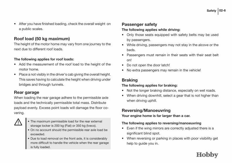
• The maximum permissible load for the rear external storage locker is 200 kg (Fiat) or 350 kg (Iveco).
• On no account should the permissible rear axle load be exceeded.
• Due to load removal on the front axle, it is considerably more difficult to handle the vehicle when the rear garage is fully loaded.
• After you have finished loading, check the overall weight on a public scales.
Roof load (50 kg maximum)The height of the motor home may vary from one journey to the next due to different roof loads.
The following applies for roof loads:• Add the measurement of the roof load to the height of the
motor home.• Place a not visibly in the driver's cab giving the overall height.
This saves having to calculate the height when driving under bridges and through tunnels.
Rear garageWhen loading the rear garage adhere to the permissible axle loads and the technically permissible total mass. Distribute payload evenly. Excess point loads will damage the floor co-vering.
BrakingThe following applies for braking:• Not the longer braking distance, especially on wet roads.• When driving downhill, select a gear that is not higher than
when driving uphill.
Reversing/ManoeuvringYour engine home is far larger than a car.
The following applies to reversing/manoeuvring• Even if the wing mirrors are correctly adjusted there is a
significant blind spot.• When reversing or parking in places with poor visibility get
help to guide you in.
Passenger safetyThe following applies while driving:• Only those seats equipped with safety belts may be used
by passengers.• While driving, passengers may not stay in the alcove or the
beds. • Passengers must remain in their seats with their seat belt
on!• Do not open the door latch!• No extra passengers may remain in the vehicle!

Safety02-7
Driving arround cornersDue to its height, a motor home begins to sway more quickly than an automobile.
The following applies for driving arround corners:• Never drive too quickly into a corner!
Driving economicallyThe engine of your motor home has not been designed to drive constantly under a full load.
The following applies when driving:• Do not keep your foot down on the accelerator!• The final 20 km/h before reaching top speed require up to
50 % more fuel!
Getting petrolA number of devices that use an open flame have been built into your motor home.
The following applies when getting petrol:• Turn off all accelerator devices (heating, refrigerator, etc.)!• Turn off all mobile phones!• Never get anything other than diesel fuel.• Never mistakenly fill the fresh water tank with fuel.
DrivingTake a trial drive before leaving on your first large journey in order to familiarize yourself with the motor home. Remember to practise reversing. The base vehicle is a commercial vehicle; adjust your driving style accordingly.
The following applies for driving:• Do not underestimate the length of the engine home. Due
to the relatively long rear overhang larger vehicles can veer to one side and, in unfavourable conditions, the rear can hit the ground.
• Be careful when driving into inner courtyards and through entrance gates.
• The motor home may start to swing from side to side in cross-winds, on wet or icy roads.
• Adjust your speed to road and traffic conditions. • Long descents with a slight gradient can become dangerous.
Adjust your speed from the very beginning to allow you to speed up if necessary without endangering other auto-mobiles.
• As a general rule, never drive faster downhill than uphill.• The motor home may be caught up in a slipstream when
overtaking or being overtaken by lorries with trailers or buses. This effect is counteracted by lightly counter-steering.
• Use foresight while driving; take regular breaks on longer drives.

Safety 02-8
2.7 Vehicle tool kit
Each vehicle comes with individual basic equipment including a vehicle tool kit and accessories:- screwdriver j- nut wrench k- nut wrench l (only if the vehicle is equipped with levelling supports)- ratchet wrench m- car jack n- chocks o- tool bag p- tool bag q
7 6
21 3 4
5
8
10
2
6 5
9
7
- pilot lamp r- towing eye s

Safety02-9
100 m
2.8 Emergency equipment
To be prepared in case of an emergency, you should always carry the three emergency devices on board and familiarize yourself with them.
First-aid kitThe first-aid kit should always be at hand and have a fixed position in your motor home. Any objects removed from the first-aid kit should be replaced immediately. Expiry dates should be checked regularly.
Reflective jacket (not included in scope of deli-very)In acc. with EN 471, we recommend that you carry and wear a reflective jacket with white retro-reflective stripes whenever you leave the vehicle on open roads and emergency strips. The driver should wear this jacket when the vehicle• comes to a stop outside city limits on an obscure rural road
because of an accident or breakdown, if the view is poor due to bad weather, in twilight or darkness, or
• when it must be secured by means of a warning triangle on the emergency strip of the engineway because of an accident or breakdown.
Warning triangleThe warning triangle should also always be at hand and have a fixed position in your motor home, preferably together with the first-aid kit.
In an emergency• Set up the warning triangle at least 100 m in front of the
danger zone!

Safety 02-10
2.9 When you stop driving
Selecting a parking space
The following applies for selecting a parking space:• Select a parking space that is as level as possible.• If possible, pick your spot in daylight.
Securing the vehicle
The following applies when securing the vehicle:• Put the vehicle in gear.• Pull on the handbrake.• If necessary, extend extra vehicle supports.
• If necessary, use blocks (not in scope of delivery).
If the temperature is below 0°C only put the handbrake on lightly and ensure that the vehicle is in gear to prevent the handbrake from freezing up!
When turning the driver‘ seat, ensure that you do not acci-dently disengage the handbrake.
Switching electric consumption:
The following applies when switching electric consump-tion:• Switch the refrigerator from 12 V to accelerator or 230 V.
Otherwise, if the engine is not on, the 12 V electrical supply will automatically turn itself off after a few minutes.
• Open the main stop valve on the accelerator cylinder and the accelerator stop valve on the consumer required.
Water system
Empty the entire water system if the vehicle is not heated when there is danger of frost. Leave the water faucets as well as all drain valves open to prevent damage from frost.
Water that has been left to stand in the fresh water tank or water pipes quickly becomes undrinkable. Therefore always flush the water pipes thoroughly with several litres of fresh water before using them.
Safety02-11
Saving energy in winter
It is very easy to save energy inside your motor home. This applies especially to heating in winter.
The following applies for saving energy:• Meter the exact use of ventilation in the vehicle and the
heating valve.• Install winter mats on the inner sides of the driver‘s cabin
and the windscreen (not included in scope of delivery).• Attach the insulating mat between the driver‘s cab and the
interior of the motor home (not included in scope of deli-very) or, for the Sphinx model, completely shut the sliding door to the driver‘s cab.
• Open the outside door as seldom and briefly as possible.• If you are camping in winter, attach a small outer tent. This
will offer protection against the cold.

Safety 02-12

Chassis
Chapter 3: Chassis
3.1 Chassis
The chassis includes parts of the frame and the axles. No technical changes may be made, as otherwise the general type approval will expire!
Technical changes may only be carried out after being released by the manufacturer.
For further information, please refer to the enclosed ope-rating instructions for the basic vehicle.
3.2 LoadingThe maximum axle loads as well as the technically permis-sible overall mass entered in the vehicle‘s documents may not be exceeded.
Weights of motor homes in accordance with 92/21/EWG
Please refer to the definition of masses for motor homes!
03-1
Definition of Masses for Motor homesThroughout Europe, EU Guideline 92/21/EWG is applicable for calculating the masses (weights) and resulting loads for motor homes. The terms and basis used for calculations are explained below.
1. Technically permissible overall massInformation regarding the technically permissible maximum weight is based on Hobby Wohnwagenwerk's specification in cooperation with the manufacturers of the previous construc-tion stages (Fiat, AL-KO, Iveco). This weight was determined in detailed calculations and tests. It is specified in the basic approvals and, for safety reasons, it must not be exceeded under any circumstances.
2. Mass when the vehicle is ready to startThe mass when the vehicle is ready to start corresponds to the mass of the empty vehicle including lubricants, tools, spare tyre (and/or repair kit), petrol (100 %), booster battery, all of the standard equipment mounted by the factory as well as 75 kg for the driver, plus basic equipment (gas, water, electric).
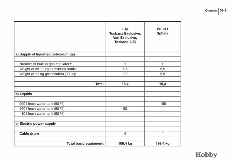
3. Basic equipmentThe basic equipment includes the masses for fresh water and the gas storage containers, which have been filled to 90 % of their total capacity. The masses for the individual models are calculated in detail as follows:
Chassis 03-2
FIATToskana Exclusive,
Van Exclusive,Toskana (LE)
IVECOSphinx
a) Supply of liquefied petroleum gas
Number of built-in gas regulators: 1 1 Weight of an 11 kg aluminium bottle: 5,5 5,5 Weight of 11 kg gas inflation (90 %): 9,9 9,9
Total: 15,4 15,4
b) Liquids
200 l fresh water tank (90 %) - 180 100 l fresh water tank (90 %) 90 - 10 l fresh water tank (90 %) - -
c) Electric power supply
Cable drum 4 4
Total basic equipment: 109,4 kg 199,4 kg

Chassis03-3
4. LoadingLoading corresponds to the difference between the "technically permissible overall mass" and the "mass when the vehicle is rea-dy to start". This value must take into consideration the masses for passengers (conventional load: 75 kg x no. of seats, driver excepted), additional equipment and personal belongings.
Check to ensure that the masses of all objects transported in the motor home have been taken into consideration, e.g. passengers, additional equipment, basic equipment and personal belongings such as clothes, food, pets, bicycles, surfboards, other sport equipment, etc.).
Under no circumstances may the technically permissible total load be exceeded when the motor home has been loaded.

Chassis 03-4
3.3 Levelling supports (Optional Extra)
The levelling supports are located in the rear area by the frame extension.
Swinging out the levelling supports• Place the crank on the hexagon head j .• Turn the crank to move the support to a vertical position.• If necessary, secure the foot k to prevent it from sinking
into the ground and place it on a firm base.• If the levelling support is in a vertical position, the support
foot will extend telescopically.• Use the crank to level the levelling supports until the vehi-
cle stands level.
Retracting levelling supports• Use crank to release levelling supports.• Continue to crank smoothly until the levelling support is once
again in its initial horizontal position.
- Do not use the levelling supports as a car jack. Their sole purpose is to stabilise the motor home when it is parked.
- Always load the levelling supports evenly.- Always retract the levelling supports and secure them
before driving.- Clean the levelling supports regularly and grease them
slightly.
2
1
2
The telescopically adjustable foot may only be extended as far as the yellow marking!

Chassis03-5
To open• Press the switch k in the entrance area down. The entrance
step will be extended automatically.
To close• Press the switch l in the entrance area up. The entrance
step will be retracted automatically.
If, due to dirt or frost, the entrance step does not func-tion properly or at all, the hinges must be cleaned or defrosted.
3.4 Entrance step
The motor homes are equipped with an electrically extenda-ble entrance step j. Vehicles based on the Fiat model have just one step (see photo) while vehicles based on the Iveco model have two steps to adjust for the extra height.
1
Always retract the entrance step before driving!
Mind the different heights of the steps and ensure that the ground in front of the entrance is firm and level.
Do not step on the entrance step until it has been comple-tely extended!
2
3

Chassis
3.5 Vehicle identification number (VIN)
On Iveco models, the 17-digit vehicle ID number is located at the front on the right-hand longitudinal beam of the frame. On Fiat models, it has been applied to the inner wheel case on the passenger‘s side. To identify it more easily, the VIN on Fiat models can also be found on a label on the left-hand side of the dashboard. In addition, the VIN is also given on the type plate of the base vehicle as well as on the Hobby type plate (in the motor compartment on the upper front cross member of the radiator). Always have your VIN at hand whenever you have a question or visit your dealer/contractual partner.
1
23
03-6
3.6 Additional pneumatic springs
Additional pneumatic springs on the rear axle (optional extra) provide a significant improvement to the motor home’s road handling and complement the standard suspension. The air bellows lift the vehicle’s tail as required.
The compressor is activated from the driver’s cabin ope-rating panel using the On/Off button j, thereby filling the bellows with air. The manometer l can be used to provide continuous information regarding the current pressure in the system. Should excess pressure occur the excess air can be released from the system using the ventilation button k.

Chassis03-7
In order to avoid damage to the air bellows during mainte-nance work they should be checked for any accumulation of waste or dirt and, if required, cleaned.
The following cleaning agents are approved for cleaning the air bellows: soap suds, methanol, ethanol and iso-propanol.
The maximum permissible operating pressure of the system is 4.0 bar.
The optimum air pressure is achieved when the vehicle is standing horizontally. The minimum air pressure must be high enough to ensure that the air bellows cannot snap through. When the vehicle is empty this pressure is approx. 0.5 bar (please check individually); when the vehicle is loaded the va-lue will be correspondingly higher, depending on the loading.
Please see the registration documents for information con-cerning the tow bar load and the rear axle load.
3.7 Towing fixture (Optional Extra)
Adhere to the permissible tow bar load and rear axle load, in particular in conjunction with loading of the rear garage.
Simultaneous use of the towing fixture and the rear load carrier is not permitted.
While manoeuvring to hitch and unhitch loads, ensure that no-one is standing between the motor home and the trailer.
Please check Iveco's User Manual for information on how to operate the pneumatic suspension of the Iveco Daily.

Chassis
3.9 Automatic transmission
As an option, your motor home can be equipped with an au-tomatic transmission (Fiat: Comfort-Matic; Iveco: Agile) which has two methods of operation: MANUAL and AUTO(MATIC). Since the clutch is engaged and released by means of an electro-hydraulic unit that is controlled by the transmission‘s control unit, the clutch pedal is superfluous and, therefore, it has been removed. Both the selected method of operation as well as the gear you are driving in are shown on the multi-function display panel.
The gearshift lever on the dashboard has three fixed positions:− the centre position for selecting the forward gear,− N for selecting the neutral position (engine is idle),− R for selecting the reverse gear.
Starting from the centre position, which corresponds to the forward gear, the lever can be moved as follows:− forwards (- position) to select a lower gear (i.e. shifting
down),− backwards (+ position) to select a higher gear,− to the left (A/M position) to select automatic or manual
mode, alternatively.
03-8
The D 75 models have a removable tow-bar. We recom-mend that you remove this when it is not required.
Due to stipulations by the manufacturer of the basic vehicle and the fixing of the so-called D value of the towing fixture no additional loading of the towing loads is possible.
Do not forget that towbar couplings, motorcycle carriers, level-ling devices and/or additional spring blades must be registered.
Please note that mounting additional equipment reduces the load your motor home can carry.
Registering accessories in the vehicle's documents
• Have your HOBBY dealer mount your externally mounted fixtures.• Take your motor home to a technical support organisation
or technical service provider (e.g. MOT).• The technical support organisation will approve the fittings
and draw up a corresponding expertise. (road traffic authorities)• Take the expertise and the registration documents, Parts
I and II, to the Driver and Vehicle Licensing Agency. They will copy the changes into the vehicle's documents.
3.8 Externally mounted fixtures

Chassis
the gas pedal to the floorboard. This will provide you with the required performance and torque to achieve the acceleration you require.
Parking the vehicleTo ensure that the vehicle is safely parked, step on the brake pedal and then shift into either first gear or reverse (R). Fur-thermore, when parking on a slope, you must also pull the hand brake.
Never leave the vehicle when the transmission is in neutral (N).
If the vehicle is not moving and you have already shifted into gear, always step on the brake pedal until you have decided to start driving. Only then should you release the brake pedal and slowly step on the gas pedal.
If the vehicle is not moving and the engine is running for a longer period of time, we recommend that you shift to neutral (N).
These three positions are not fixed, i.e. after the lever has been moved it jumps back to the centre position.
Manual operationThis method of operation allows the driver to select a suitable gear according to the conditions under which the vehicle is being driven. Switch gears as follows:
• Move the lever in the direction of (+) to shift up or in the direction of (-) to shift down. Do not let go of the gas pedal while you are shifting gears.
The system will only allow you to shift when such an action will not prevent the motor or the transmission from functio-ning correctly. As soon as the motor reaches idle speed, the system will automatically shift down (e.g. when braking).
Automatic operationThe lever must be pressed in the direction of A/M in order to switch automatic operation on or off. The system auto-matically shifts gears on the basis of the vehicle‘s speed, the engine rpm and the position of the gas pedal. However, by pressing the lever you can still shift gears without having to switch off the AUTO mode of operation. If necessary, the system will shift down one or more gears when you press
03-9

Chassis
If you want to shift into first gear when in reverse gear (R) or vice versa, the gearshift lever may only be moved when the vehicle is standing completely still and you are stepping on the brake pedal.
For further information, please refer to the operating in-structions for the base vehicle. Please familiarise yourself sufficiently with the operation of the automatic transmissi-on before you use your vehicle the first time.
03-10
Do not use the gas pedal as a means of holding the ve-hicle in one spot (e.g. on a slope). Instead, use the brake pedal and step on the gas only when you start to drive.

Wheels, tyres, brakes04-1
Rim size Fiat Ducato Iveco Daily
16'' 180 Nm 290 - 350 Nm
15'' 160 Nm –
Chapter 4: Wheels, tyres, brakes
4.1 Wheels
If you are driving a new vehicle, or after changing a tire, tighten the wheel bolts or nuts after you have driven the first 50 km and then again after the following 100 km. For your safety, do not use any tires or fixing material other than what was originally stipulated. Wheel bolts and nuts should then be checked regularly to ensure that they fit tightly.
Tightening torque for wheel nuts and bolts:
4.2 Tyres
Use only tyres that have been entered in the vehicle's documents. Other tyre sizes may only be used if they have been permitted by the manufacturer of the basic vehicle.
Driving to protect your tyres• Avoid braking sharply and racing starts.• Avoid long drives on poor roads.• Never drive an overloaded vehicle.
Tubeless tyres have been mounted on your HOBBY motor home. Under no circumstances may tubes be inserted in these tyres!
Winter tires are mandatory in many EU countries!
If you are driving in snow, ice or sludge in one of these countries, your vehicle must be fitted with tires that have the "M+S" symbol. You may be fined if you ignore this legal requirement.

Wheels, tyres, brakes
1 2 3
04-2
4.3 Tyre pressure
The inflation pressure of all tyres as well as the spare tyre should be checked approx. every 4 weeks and before you go on longer journeys.
The following applies when checking inflation pressure:• Check the pressure only when the tyre is cold.• If checking or correcting the pressure of a warm tyre, the
pressure must be 0.3 bar higher than for a cold tyre.
The following applies for inflation pressure:- correct inflation pressure j.- inflation pressure too low k.- inflation pressure too high l.
If the pressure is too low, this may cause overheating of the tyre, possibly resulting in severe damage to the tyre.
For the correct inflation pressure, please refer to the table in the chapter on “Technical Data“ or the operating instructions for the basic vehicle.
4.4 Tread depth
Replace your tyres as soon as the tread depth is only 1.6 mm.
Tyre manufacturers‘ recommendations• Irrespective of their tread depth, tyres should be changed
every 6 years.• Avoid hard impacts against curbs, potholes or other obstacles.
Tyres age even if they are used seldom or not at all.
Tyres may not be exchanged crosswise, i.e. from the right side of the vehicle to the left and vice versa.
The minimum tread depth gives you only the barest amount of safety while driving. The following recommendations must be observed:Safety limit in summer: 3.0 mmSafety limit in winter: 4.0 mm

Wheels, tyres, brakes04-3
4.6 Spare tire
A spare tire is part of the scope of delivery only for tan-dem axle vehicles with an AL-KO chassis (D 75) and the Sphinx models.
Spare tire on the AL-KO chassis
To remove the spare tire on the AL-KO chassis, use a he-xagon spanner to remove the two screws on the spare tire holder. Insert the crank on the left-hand side of the spare tire holder, unhinge the tire holder, lower the spare tire to the ground and remove it.
For information on the Iveco spare tire, please refer to the operating instructions for the base vehicle.
4.5 Wheel rims
Use only those wheel rims listed in the vehicle‘s documents. Please observe the following points, should you wish to use other wheel rims.
The following applies when using other wheel rims:- Size,- construction,- injection depth and- The load bearing capacity must be sufficient for the per-
missible total axle weight.- The cone of the fastening screw must correspond to the
construction of the wheel rim.
Adaptations are only permitted if these have been released by the manufacturer.
Aluminium wheel rims must be tested separately for each type of vehicle. The screws used on aluminium rims may not be used for steel rims.

Wheels, tyres, brakes 04-4
4.7 Tyre repair kit
Do not use the tyre repair kit if the tyre was damaged as a result of driving without air. Small cuts, especially in the tyre tread, can be resealed using the tyre repair kit. Do not remove foreign bodies (such as screws or nails) from the tyre. The tyre repair kit can be used at outside temperatures to a mini-mum of approx. -30°C.
A Shake the bottle. Open the fill hose j on the bottle (foil seal is thereby punctured).
There is an expiry date on the tire repair kit. Therefore, please note this date. Kits that have expired no longer offer a guarantee that they will function properly.
Wheels, tyres, brakes04-5
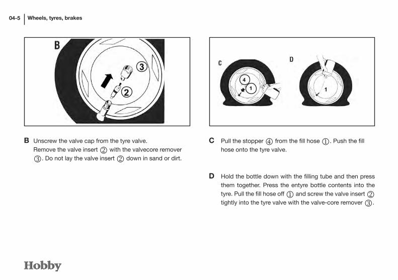
C Pull the stopper m from the fill hose j. Push the fill hose onto the tyre valve.
D Hold the bottle down with the filling tube and then press them together. Press the entyre bottle contents into the tyre. Pull the fill hose off j and screw the valve insert k tightly into the tyre valve with the valve-core remover l.
B Unscrew the valve cap from the tyre valve. Remove the valve insert k with the valvecore remover l. Do not lay the valve insert k down in sand or dirt.

Wheels, tyres, brakes 04-6
E Open the air hose n on the tyre valve. Insert the plug
o into the cigar lighter socket. Then pump the tyres (Fig. p). do not operate the electric air pump longer than 8 minutes! Danger of overheating! If sufficient air pressure is unattainable, drive 10 meters (either forward or in reverse) so that the sealant can be evenly distribut-ed within the tyre. Repeat the pumping process. Resume driving immediately, so that the sealant can be evenly distributed within the tyre.
Maximum speed: 80 km/h. Especially in curves. Check tyre pressure after driving 10 minutes. If the tyre pressure has fallen under this minimum value q, you may not drive any further.
If the minimum value is still indicated q correct the tyre pressure according to Table 12.2. Drive carefully to the nearest workshop and have the tyre replaced.
Danger of accidents: If the required tyre pressure is still unattainable the tyre is too severely damaged. In this case the tyre repair kit can no longer provide an effective seal. Do not, therefore, drive any further. Notify a service station or the 24-hour service hotline.

Wheels, tyres, brakes
Warning when changing the tire
Changing a tire• Place a firm base, such as a piece of wood, underneath
the car jack if the vehicle is on soft ground.• Insert the car jack into the appropriate mounting holes.• Turn the wheel spanner a few times to loosen the wheel
mounting screws, but do not remove them.• Jack up the vehicle until the wheel is 2 -3 cm above the
ground.
04-7
The car jack may only be inserted in the appropriate mounting holes! If the car jack is attached in other places, this may cause damage to the vehicle or even accidents if the vehicle falls off the jack.
The car jack is to be used only for changing tires. It may never be used when working underneath the vehicle! Danger of death!
The levelling supports may not be used as a car jack!
When changing a tire, please also observe the vehicle manufacturer‘s operating instructions.
Danger of accidents! Have the tyres replaced at the nearest service station.
F Adhere the provided sticker to the combination panel within sight of the driver. Dispose of used tyre repair kit at a service station.

Wheels, tyres, brakes
It is in your own interest to have the brakes checked regularly by your Fiat or Iveco workshop.
04-8
For further information, please refer to the Fiat Ducato or Iveco Daily operating instructions.
• Remove the wheel mounting screws and lift off the tire.• Place the spare tire on the wheel hub and align it.• Screw the bolts on and tighten them in a diagonal sequence.• Lower the car jack and remove it.• Tighten the wheel mounting screws evenly with the wheel
spanner. Please refer to the operating instructions for the base vehicle for the specified value of the tightening torque of the wheel mounting screws.
• Place the tire you have removed in the (possibly existing) spare tire holder and then shut the holder.
4.8 Brakes
The components in the brake system are part of the General Type Approval (“Allgemeinen Betriebserlaubnis“, ABE).If you change the components in the brake system, the type approval expires. Any changes are only possible if they have been released by the manufacturer.
The following applies when maintaining the brake system:• Check the level of brake fluid regularly.• Check the brake system and brake hoses regularly for lea-
kage. Martens often gnaw at rubber hoses.• Use only brake fluids with the same qualities as those
fluids already in the brake circuit.

Exterior Structure05-1
Storage flap jToilet flap k
Gas box flap l
Chapter 5: Exterior Structure
5.1 Overview of tank and service flaps
60 ES Van Exclusive 69 EL Toskana Exclusive
60 KL Van Exclusive 69 GL Toskana Exclusive
j
j
j j j
j
j j
jk
k
k
k
j
l
l
l
Exterior Structure 05-2
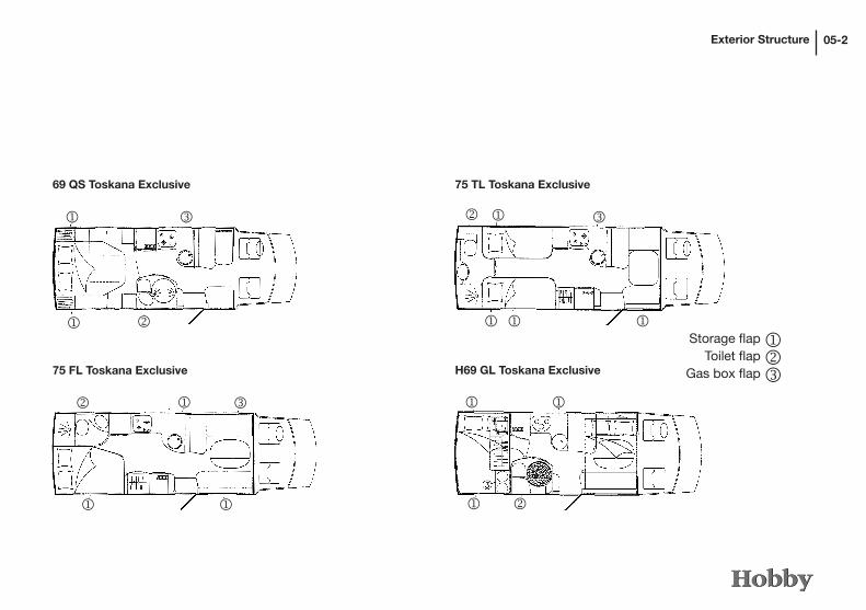
69 QS Toskana Exclusive
75 FL Toskana Exclusive
75 TL Toskana Exclusive
H69 GL Toskana Exclusive
j
j
j
j j
j
j j j
j j
j
k
k
k
k
l
l
l
Storage flap jToilet flap k
Gas box flap l

Exterior Structure05-3
Storage flap jToilet flap k
Gas box flap lA77 EM Spinx
A77 GM SphinxH75 FL Toskana Exclusive
H75 UC Toskana Exclusive
j
j j
j j
jj
j
jjj
jj
k
k j
jjj
jj
k
k
l
ll
l

Exterior Structure 05-4
Exterior Structure
1
2
05-5
1
2
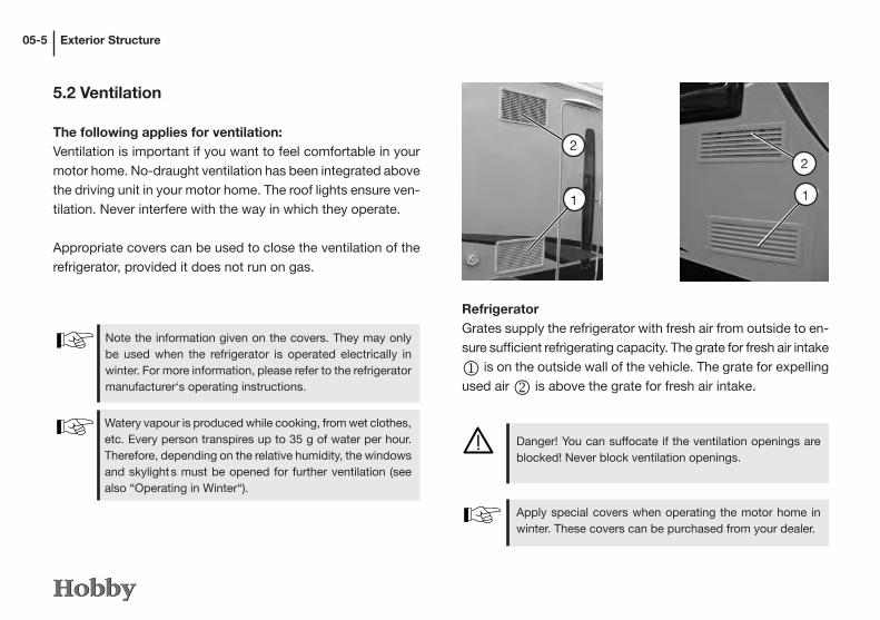
5.2 Ventilation
The following applies for ventilation:Ventilation is important if you want to feel comfortable in your motor home. No-draught ventilation has been integrated above the driving unit in your motor home. The roof lights ensure ven-tilation. Never interfere with the way in which they operate.
Appropriate covers can be used to close the ventilation of the refrigerator, provided it does not run on gas.
Note the information given on the covers. They may only be used when the refrigerator is operated electrically in winter. For more information, please refer to the refrigerator manufacturer‘s operating instructions.
Watery vapour is produced while cooking, from wet clothes, etc. Every person transpires up to 35 g of water per hour. Therefore, depending on the relative humidity, the windows and skylight s must be opened for further ventilation (see also “Operating in Winter“).
RefrigeratorGrates supply the refrigerator with fresh air from outside to en-sure sufficient refrigerating capacity. The grate for fresh air intake
j is on the outside wall of the vehicle. The grate for expelling used air k is above the grate for fresh air intake.
Danger! You can suffocate if the ventilation openings are blocked! Never block ventilation openings.
Apply special covers when operating the motor home in winter. These covers can be purchased from your dealer.

Exterior Structure 05-6
Removing the ventilation grate• Push the lock(s) l up as far as they will go or turn the
lock(s) m to the right (for Thetford: push both locks towards the centre).
• Carefully lift open the ventilation grid on the left-hand side (Thetford: lift up).
• Then pull the right-hand side out of the bracket (Thetford: press the lower edges down out of the bracket).
1
We recommend that you remove the ventilation grate if the outside temperature is very high. This allows more air to permeate to the refrigerator, intensifying refrigeration. The ventilation grids must remain firmly mounted while driving or when it is raining.
HeatingThe heating system is supplied with fresh air from outside j. This ventilation flap also permits exhaust air from the system to escape.
Blocked ventilation openings can lead to suffocation! Therefore, never block ventilation openings. When operating in winter ensure that the chimney outlet is not blocked.
3
4
Exterior Structure05-7
5.3 Opening and closing doors and flaps
Keys to the vehicleThe following keys are delivered with the motor home:
- two keys to fit the following locks on the base vehicle: - driver‘s and passenger‘s doors- a code card.
In addition, a self-adhesive aluminium plate is included in delivery, engraved with the key number of the base vehicle.
Note the manufacturer‘s operating instructions for the
basic vehicle.
- two keys that fit the following locks on the structure: - entrance door - service flaps - toilet flaps
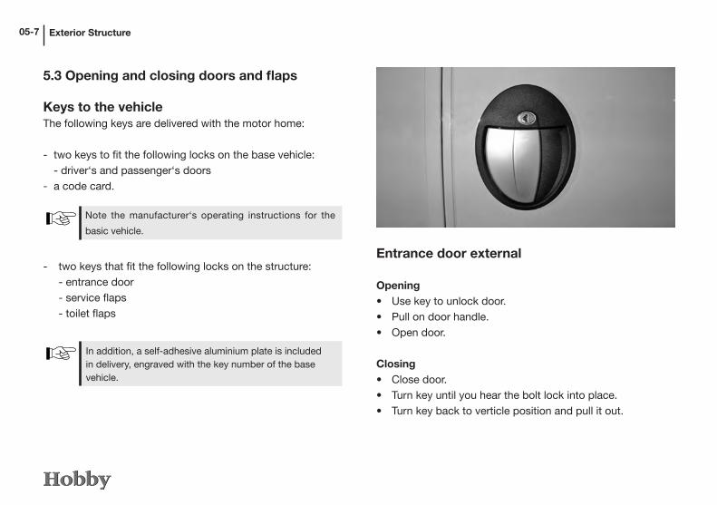
Entrance door external
Opening• Use key to unlock door.• Pull on door handle.• Open door.
Closing• Close door.• Turn key until you hear the bolt lock into place.• Turn key back to verticle position and pull it out.

Exterior Structure 05-8
To prevent damage to locks and door frames, the inner door handle must be positioned horizontally and not slanted upwards.
The entrance door is your escape route in an emergency. Never barricade the door from the outside!
Entrance door internal
Opening• Push the bolt down.
This allows a door which has been locked from the outside to be opened from the inside.
Exterior Structure
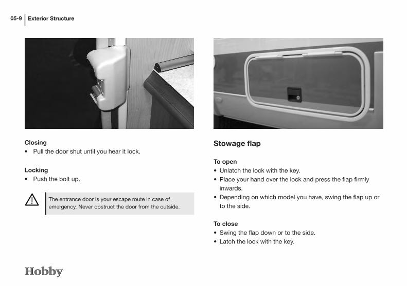
Stowage flap
To open• Unlatch the lock with the key.• Place your hand over the lock and press the flap firmly
inwards.• Depending on which model you have, swing the flap up or
to the side.
To close• Swing the flap down or to the side.• Latch the lock with the key.
05-9
The entrance door is your escape route in case of emergency. Never obstruct the door from the outside.
Closing• Pull the door shut until you hear it lock.
Locking• Push the bolt up.

Exterior Structure 05-10
Garage (storage locker) flap
To open• Unlatch the lock with the key.• Place your hand over the lock and press the flap firmly
inwards.• Swing the flap to the side.
To close• Swing the flap shut.• Latch the lock with the key.
Toilet flap
To open• Use key to unlock flap j.• Press both buttons (j and k) and open flap.
To close• Press flap until it locks into place.• Use key to lock flap j.
1
2

Exterior Structure05-11
2
1
Exterior gas supply
At the customer‘s request, the motor home can be fitted with an exterior gas supply k. Equipment that uses gas, such as a gas grill or a gas lamp, can be supplied from outside the motor home. The exterior gas supply is located below the gas box flap.
Opening• Pull the cover plate j of the flap towards you.
Closing• Press the cover plate j of the flap shut until you hear it
lock into place.
Fresh water filler neck
Opening• Use key to unlock j.• Turn lid k firmly and remove.
Closing• Insert lid k and turn it closed.• Use key to lock j.
12

Exterior Structure 05-12
1
Please refer to the separate operating instructions from Fiat or Iveco for information on how to operate the petrol cap.
Tank filler cap
The petrol cap for all Van Exclusive and Toskana (Exclusive) models is located behind the driver's door behind a flap in the lower section of the B pillar.
Opening• Pull the flap open by inserting your finger into the convex
opening j and pulling it outwards.Closing• Push the flap until it locks.
5.4 Roof rail
The following applies when loading the roof rail:• Only store light items of luggage on the roof.• Lash the roof load securely and ensure that it cannot slip
or fall off.• Do not overload the roof! The heavier the roof load, the
worse the vehicle’s performance.
The maximum overall load is 50 kg.

Exterior Structure05-13
• Observe the maximum permissible axle loads when loa-ding.
• Add the measurements of the roof load to the height of the vehicle.
• Place a note with the overall height in a visible position in the driver’s cabin to avoid having to calculate it when passing under bridges or through archways.
Only transport roof loads using an additional, suitable roof rack.
5.5 Bicycle carrier (Optional Extra)
The motor home’s handling when driving is significantly different when the bicycle carrier is in use. The driving speed should be adjusted accordingly to take this into consideration:
• Even if loading is perfect the critical speed is dramatically reduced.• The driver is responsible for the secure fastening of the bicycles. Even when unloaded and folded up the carrier must be secured using the clips provided.• Ensure that the existing lighting equipment is not completely or partially obscured by any loads.

Exterior Structure 05-14
Due to the construction method of the rear wall, the ma-nufacturer has not planned bicycle carriers for the Sphinx models.
The maximum permissible loads for the bicycle carriers are 50 kg.
5.6 Load carrier (Optional Extra)
Your motor home can subsequently be fitted with a carrier from an accessory dealer which, for example, is equipped with a modification kit for attaching a motorcycle or motor scooter. The driver is responsible for the safe and stable fa-stening of the load.
• The chassis of the motor home has been designed to carry a maximum load of 130 kg.
• Never exceed the permissible rear axle load.• The load carrier reduces the rear ramp angle of the ve-
hicle. When driving over uneven surfaces the carrier can touch the ground.
• When the load carrier is fully loaded the rear axle is sub-ject to an additional load and the front axle is unloaded. This can result in significant changes in the motor home’s handling, steering and braking performance.
• The rear number plate must be centrally mounted bet-ween the load carrier’s number plate lights.
• Please note, when the load carrier is in use it is forbid-den to use any existing towing fixture which may still be accessible simultaneously.

Exterior Structure05-15
5.7 Sun awning (Optional Extra)
Depending on the model, your motor home has an awning that is either integrated in the edge trim or attached to the side wall.
• An awning offers protection from the sun, not against the elements.
• Do not place people or obstacles in the extension/retraction area of the awning.
• The awning winding mechanism is fitted with a mechanical block control to limit the extent to which it can be extended. Never attempt to exceed the block control by force.
• Always support the awning with the integrated struts when extended.
• The awning must always be completely retracted and secu-red before driving.
Extending • Insert the hook on the crank into the grommet on the win-
ding mechanism.• Hold the crank with one hand on the upper twist grip and
the other on the lower twist grip. During the operating procedure gently pull the crank towards you and hold it as vertically in the grommet as possible.
• Turn the crank clockwise until the awning has been exten-ded to the desired position.
• Remove the crank.• Unfold the telescopic rods on the inside of the drop tube
and use them to support the awning.
Retracting• Retract the telescopic rods, fold them up and secure them.• Insert the hook on the crank into the grommet on the win-
ding mechanism.• Turn the crank anti-clockwise until the awning has been
fully retracted and is secured.• Remove the crank and store it in the vehicle.
If the canvas is slack when extended, retract the awning until the canvas is tightly stretched again.

Exterior Structure 05-16

Interior Structure06-1
Stowage cabinets
To open• Press the pushbutton j to unlock the flap.• Pull on the handle until the flap opens.
To close• Use the handle to press the flap shut until you can feel it
close and lock.
1
Chapter 6: Interior Structure
6.1 Opening and closing doors and flaps
Close all flaps and doors properly before driving. This avoids them opening accidentally while driving and objects falling out.

Interior Structure 06-2
Store only light objects in the upper stowage cabinets.
Front stowage cabinets
To open• Pull on the handle and swing the flap up.
To close• Use the handle to press the flap shut until you can feel it
lock into place.
Kitchen cupboard doors Depending on the model, concealed locking handles have been fitted.
To open• Turn the handle j (located directly behind the flap)
down.• Pull on the flap until it opens.
To close• Press the flap shut until you can feel it close and lock.
1

Interior Structure06-3
Furniture doors with turning knob
• Turn the knob to open or shut the door.
Furniture doors with handle
• Push the handle to open and shut the door.

Interior Structure 06-4
Doors with snap locks
To open• Briefly push the door handle until it snaps open.• Open the door.
To close• Push the door handle until the lock snaps into place.
1
Drawers with a pressure lock
To open• Press the push-button j to unlock the pull-out.• Pull on the handle until the pull-out opens.
To close• Use the handle to press the flap shut until you can feel it
lock into place.

Interior Structure06-5
Bar in the entrance area (layout/model-specific)
To open• Pull on the handle and swing the door outwards.
To close• Use the handle to press the flap shut until you can feel it
lock into place.
Doors with push locks
To open• Depress the push lock until the knob pops out.• Carefully pull the knob and open the door.
To close• Push the door closed using the knob.• Depress the push lock until the knob locks into place and
the door is fastened.

Interior Structure 06-6
1
Lock the media unit or TV holder before driving.
6.2 Television holder for flat-screen monitor
To unlock, press in on the metal rail j. Then extend the TV mount. 230 V power sockets and an aerial socket for the TV and/or receiver are located directly adjacent to the holder.
Sliding doors
Cupboard under the bed, washroom door
To open• Grasp sliding doors by the centre bar and push them both
outwards.
To close• Grasp the doors by the centre bar and push them shut
until they meet in the middle.
The mounted TV may not weigh more than 8 kg. When driving, we recommend that you remove the TV from the mount and store it securely.
In order to use the TV, the hand brake must be on.

Interior Structure06-7
This table is not fastened to the floor. Before driving, lower the table and secure it to prevent it from shifting.
6.3 Tables
Lowering the table in the centre seating arrangement
• Push the switch j on the table leg up.• Fold in the lower part of the table leg until you feel it click
into place.• Unhinge the table and hook it to the lower fastening.
1
TV mount for flat screen TV, 3-way universal hinged bracket
To pull the mount out or fold it in, move the telescopic arm manually at the joints marked j , k and l.
2
1
3

Interior Structure 06-8
Table extension
• Turn the wheel j under the table until the table is loose.• Lift the table slightly and pull it out until the extra leaf is
fully visible.• Swing the leaf upwards towards the side wall.
1
• Push the table towards the leaf and place them in the appropriate openings.

Interior Structure06-9
Pillared tableWhen lowered, the pillared table can also be used as a base frame for the bed.
To lower• Lock the swivel lock on the table top by firmly tightening
the knurled wheel k.• Pull the table top off by pulling it straight up.• Pull the middle section of the pillar l off the foot m and
remove it.• Place the table top on the foot m.
2 4
3
Lowering the table
Release the table top
Pull the table top off by pulling it up
Pull out the pillar
Then replace the table top on the table foot
Fasten the table top
1 2
3 4

Interior Structure 06-10
Turning function of the pillared table
• Loosen the swivel lock on the table top by loosening the knurled wheel k.
• Swivel the table top to the desired position.• Lock the swivel lock of the table top.
Folding down the edge of the tableThe table in the seating arrangement has an edge that can be folded down (layout/model-specific) to provide you with more room for moving in the vehicle.
Function• Push in the supporting rails j under the main part of the
table.• Lower the edge of the table slowly; do not let it drop down.
1

Interior Structure06-11
Hanging tableWhen lowered, the hanging table can be used as a base frame for the bed.
To lower• Fully retract the lower, pivotable table top j and use the
locking pin k to lock it.• Raise the front end of the table top l by approx. 30°.• Pull down the lower section of the table foot m and remove
it.• Pull the table top out of the upper wall bracket n.• Raise the front end of the table top by approx. 30° and hook
it into the lower wall bracket o.
• Place the shortened supporting leg p at the front edge of the table top on the floor.
To swivel out• Pull the locking pin k.• Swivel the lower table top j to the desired position.
2
1
5
3
4
6
7

Interior Structure 06-12
6.4 Bed conversion
The seating arrangements can be rearranged as comfortable beds for sleeping.
To rearrange• Remove all cushions.• Lower the table. (see 6.3 Tables).
• Pull out the extension of the bedj and place additional cushions along the outer wall.
• Place the cusions from the seating arrangement on top and pull them together towards the middle of the table.
• Fill the empty spaces with the backrests. To do this, turn the backrests around and place them with
the wider side towards the front or back wall.
1

Interior Structure06-13
Converting the Transverse Seat
In order to use the additional bed in the rear, the transverse seat must be converted.
Conversion• Remove the seat and back cushions.• Lower the pillared table.• Fold the cushion j cover forward by 180° and place it
on the pillared table.
1
Widening the beds (Optional Extra)
In those models with individual beds above the rear garage, the two beds can be widened or joined by folding out an additional plank.
• Open the flapjunder the additional plank and take out the access ladder.
• Fold the additional plank kforward and hook the access ladder securely into the appropriate holes.
• Place the two additional cushions on the surface.
1
2
Interior Structure 06-14
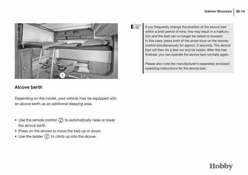
Alcove berth
Depending on the model, your vehicle may be equipped with an alcove berth as an additional sleeping area.
• Use the remote control k to automatically raise or lower the alcove berth.
• Press on the arrows to move the bed up or down.• Use the ladder j to climb up into the alcove.
1
If you frequently change the position of the alcove bed within a brief period of time, this may result in a malfunc-tion and the bed can no longer be raised or lowered.In this case, press both of the arrow keys on the remote control simultaneously for approx. 2 seconds. The alcove bed will then do a test run and be raised. After this has finished, you can operate the alcove bed normally again.
Please also note the manufacturer's separately enclosed operating instructions for the alcove bed.

Interior Structure06-15
• For protection, the alcove berth function can be switched off (0).
• Turn the key from (1) to (0) and pull it out. The alcove berth can no longer be moved.
.
• The maximum load for the alcove berth is approx. 200 kg.• Never use the alcove berth without setting up the safety
mesh.• Never leave children unminded in the alcove berth.• The alcove berth must be raised before driving.• Ensure that the lights attached underneath the alcove
berth are turned off.
2
Fold-away bed
The 60 KL Van Exclusive model has a fold-away bed that can be lowered from above the seating arrangement as an additional bed.
To operate• In order to use the bed, you must first fold down the edge
of the table. j• Use the switch in the entrance area k to move the bed to
the middle of the vehicle. Once it has reached the correct position, the bed will automatically stop.
2

Interior Structure 06-16
6.6 Cushion arrangementsRearranging the cushions
DL 500 GESC Van Exclusive
• Slowly lower the bed manually (a pneumatic spring gives you assistance). At the same time, the pillared table will automatically be lowered.
• To return the bed to its storage position, first fold it up and then use the switch to move it back to its original position.
• Lower the fold-away bed slowly; do not let it drop sud-
denly.• Before driving, the fold-away bed must be in its storage
position.• Ensure that there are no objects on the table and se-
ating benches.• When raising the fold-away bed and returning it to its
storage position, ensure that there are no objects bet-ween the bed and the side wall.
• The fold-away bed can hold a maximum load of 200 kg.
1
Interior Structure06-17
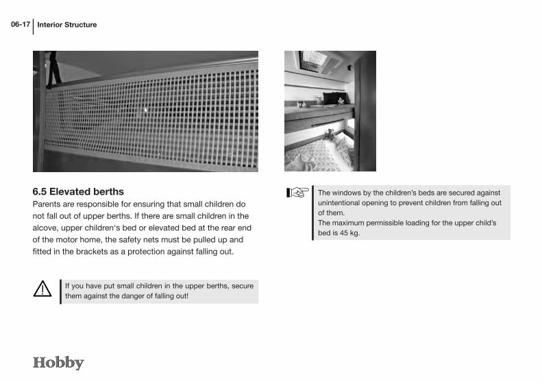
6.5 Elevated berthsParents are responsible for ensuring that small children do not fall out of upper berths. If there are small children in the alcove, upper children‘s bed or elevated bed at the rear end of the motor home, the safety nets must be pulled up and fitted in the brackets as a protection against falling out.
If you have put small children in the upper berths, secure them against the danger of falling out!
The windows by the children’s beds are secured against unintentional opening to prevent children from falling out of them.The maximum permissible loading for the upper child’s bed is 45 kg.

Interior Structure 06-18
6.6 Washroom with Sliding Wall
You can slide the washroom elements in the Siesta 65 FL model in order to use the shower.
• Press the lever j below the wash basin up and slide the wash basin together with the back wall along the guide rail towards the toilet.
1
• Extend or unfold the shower walls and pull the tap out of its anchorage so that it can be used as a shower head.
• Put everything back into place by folding in the shower walls and pushing them back, and then push back the wash basin wall until you can feel it lock into place.
Before sliding the elements, turn the hand shower 90°!
While driving, the washroom with Sliding Wall must be firmly secured and locked into its basic position.

Interior Structure06-19
6.7 Cushion arrangements (Back cushions: Optional Extra)
The back cushions delivered by the manufacturer have an ergonomic shape and, therefore, they cannot be used when converting the arrangement into a bed.
As an option, the back cushions are available as a Optional Extra.
Rearranging the cushions60 ES Van Exclusive
Additional cushion
1040x480x125
Additional cushion
420x420x125

Interior Structure 06-20
Rearranging the cushions69 EL Toskana Exclusive
Rearranging the cushions69 QS Toskana Exclusive
Additional cushion
640x525x125
Additional cushion
945x625x125 Additional cushion
524x455x125
Additional cushion
1560x410x125
Interior Structure06-21
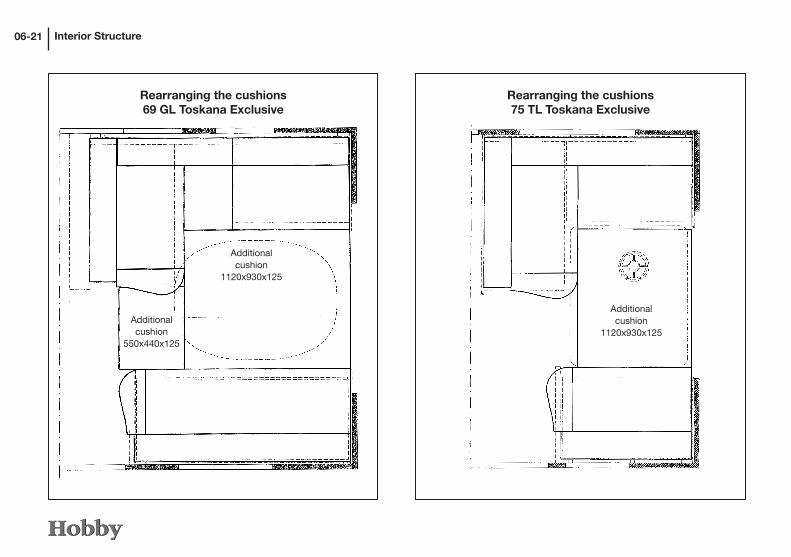
Rearranging the cushions69 GL Toskana Exclusive
Rearranging the cushions75 TL Toskana Exclusive
Additional cushion
550x440x125
Additional cushion
1120x930x125
Additional cushion
1120x930x125

Interior Structure 06-22
Rearranging the cushions75 FL Toskana Exclusive
Rearranging the cushions600 FS
Additional cushion
545x455x125
Additional cushion
1210x940x125
Additional cushion
1550x580x125
Additional cushion
540x300x125

Interior Structure06-23
Rearranging the cushionsA77 GM Toskana Exclusive
Rearranging the cushionsA77 EM Toskana Exclusive
Additional cushion
1095x580x125
Additional cushion
1095x580x125

Interior Structure 06-24
6.8 Windows
Knockout windows with locking hooks
Opening• Press the knob of the bolts and turn them to a vertical position.• Press the window outwards until you hear a click. The window
will automatically remain in this position. The width of the opening is adjustable in several stages.
Closing• Raise the window slightly so that the hook unlocks.• Close the window.• Press the knob of the bolts and turn them to a horizontal
position.
Combined sunshade and insect screenSunshades and insect screens are integrated in the window frame, and it is possible to combine them. The combined shade can be adjusted in several positions.
Adjusting the sunshade• Push evenly up or down on the left and right outer metal
rail of the sunshade.
Shifting the insect screen• Push the sunshade down and use the latch of the insect
screen to push it to the desired position.
Interior Structure06-25
2
1
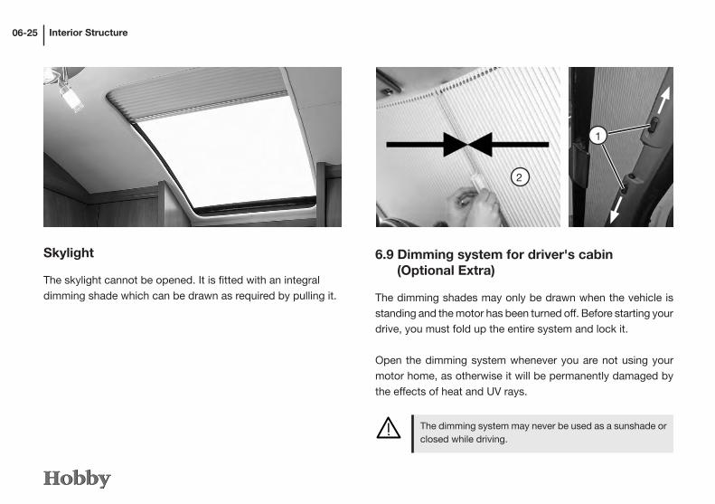
6.9 Dimming system for driver's cabin (Optional Extra)
The dimming shades may only be drawn when the vehicle is standing and the motor has been turned off. Before starting your drive, you must fold up the entire system and lock it.
Open the dimming system whenever you are not using your motor home, as otherwise it will be permanently damaged by the effects of heat and UV rays.
The dimming system may never be used as a sunshade or closed while driving.
Skylight
The skylight cannot be opened. It is fitted with an integral dimming shade which can be drawn as required by pulling it.

Interior Structure 06-26
6.10 Skylight
Safety instructions
• Never open the skylight in strong winds/rain/hail, etc. or if the temperature outside is below -20°C!
• Remove snow, ice or excessive dirt before opening. Ensure there is sufficient room before opening the skylight under trees, in garages, etc.• Do not use force to open the roof skylight when covered
by ice or snow as this could break the hinges and ope-ning mechanism.
• Do not stand on the skylight.• Close and bolt the skylight before driving. Open the insect screen and pleated material (resting position).• If the sunlight is very strong, pull the sunshade only 3/4
closed, otherwise there is a danger of heat build-up.
The vents for ventilation must always remain open! Never shut or cover up these vents!
Before driving, ensure that the skylight is securely bolted.
3
4
Front system k• To open the locking mechanism, push the locks j
outward. (Press the lock m together)• Press the clasp together in the middle. The magnetic lock
will automatically lock.
Side system l• Draw the clasp across to the rabbet. The magnetic lock will
automatically lock.

Interior Structure06-27
Opening• Turn the crank to its user position. By turning the crank
clockwise, you can now open the skylight to the desired position. When the maximum opening angle of 60° has been reached you will feel resistance.
Closing• Turn the crank anti-clockwise until the skylight is closed
and you can feel resistance. The crank can be folded back into the crank niche when the skylight is closed. To ensure safe closure the crank should be folded back into the crank niche. Check the skylight is closed by pushing against the glass with your hand.
Large roof bonnet
• There are three different positions for opening the skylight by turning the crank anti-clockwise. Press the locking button and open the skylight to the desired position by turning the crank before locking it into position. The maxi-mum opening angle is 50°.
Closing• Release the crank from the locking position and close the
skylight. The skylight is automatically locked when it has been fully closed.
Opening
Before opening the skylight, check that the outside area above the skylight is clear.
Small roof bonnet

Interior Structure 06-28
1
Round roof light
To open• Pull the lower end of all three locking mechanisms j
towards the middle of the window and release them.• Push the full surface of the roof bonnet up until it locks
into place.
To close• Close the roof bonnet.• Press the locking mechanisms j firmly until they lock
into place.
Dimming shadePull the handle of the shade to any desired position or until the latch locks into the handle of the insect screen.
Insect screenPush the clasp of the insect screen against the clasp of the shade until the latch locks into the clasp.

Interior Structure06-29
All of the motor homes on the Fiat base vehicle have pivo-ting driver‘s and passenger‘s seats, which can be used to extend the number of seats available in the superstructure. To operate these pivoting seats, please refer to the opera-ting instructions for the base vehicle.
Swivelling seats• Put the armrests up.• Move the seat to the middle position.• Release the lever to swivel the seat. The seat will be relea-
sed from the locking position.• Push the seat belt buckle down to avoid damaging it.• Swivel the seat to the desired position.
6.11 Pivoting seats in the driver‘s cab
All of the motor homes on the Fiat base vehicle have pivo-ting driver‘s and passenger‘s seats, which can be used to extend the number of seats available in the superstructure. To operate these pivoting seats, please refer to the opera-ting instructions for the base vehicle.
• Before driving turn all swivelling seats in to face in the driving direction and lock them into place.
• Leave the seats locked to face in the driving direction while driving. Do not swivel them.
• When the vehicle is stationary: when swivelling the driver’s seat make sure that the handbrake is not relea-sed by accident.

Interior Structure 06-30
Setting the height of the head rests• Take hold of the cushion on the head rest and push it to the
desired position.
6.12 Construction of the seats
Cushion fastenings
The seat and back cushions are held in place by an anti-slip mat.
Ensure that the seat cushions and backrests are fastened securely and correctly.
Arm rest in the seating arrangement (model-specific)
To extend• Pull the arm rest up until you feel it lock into place.
To retract• Pull the safety clamp j up until the arm rest is released.• Slowly lower the arm rest.
1

Interior Structure06-31
Additional belt rack
As an option, the Sphinx models can be fitted with a so-called belt rack facing towards the rear, which increases the number of seats that can be used while driving from four to six.
The height of the belt connector can be adjusted manually by pressing knobs j and k.
When using the vehicle with 6 people, ensure that the permissible axle loads as well as the technically permissi-ble maximum weight is not exceeded.
2
1
Converting the L-shaped seating arrangement
If you wish to use the outer seat in models with an L-shaped seating arrangement or the seats in the H75 UC model, you must convert these before you start to drive.
• Remove the seat and back cushions.• Fold back the cushion cover j by 180° and place it on
the crossbench.• Open the locking bolt k swing the supporting wall out by
90° and then shut the locking bolt k.
2
1

Interior Structure 06-32
6.13 Seatbelts in the caravan
The seats in the middle seating arrangement facing the direction of traffic have been fitted with seatbelts.
Buckling the seatbeltDo not twist the seatbelt.• Grasp the tongue and insert it in the lock of the seatbelt
until you hear it snap shut.
• Fasten seat belts before driving and keep them fastened while driving.
• Do not damage or jam the seatbelts. Damaged seatbelts should be replaced by an authorised workshop.
• Do not alter the seatbelt fixings; the automatic retraction system or the buckles.
• Only use each seatbelt for one adult. Do not fasten ob-jects and people using only one seatbelt.
• Seatbelts alone are not suitable for persons under 150 cm tall. In such cases use additional restraining equip-ment.
• Replace seatbelts after an accident.• Do not twist the seatbelt; it should fit closely to your
body.
• Guide the upper part of the seatbelt over your shoulder and diagonally across your chest.
• The lower part of the seatbelt fits across your hips.
Unbuckling the seatbelt• Press the button on the lock of the seatbelt to unlock the
tongue.
Please note the overview of the seating arrangements for your vehicle. Certain seats may not be used while driving!

Interior Structure06-33
Seats 1 - 4: may be used while driving.Seat 5: must not be used while driving.
6.14 Overview of the seating arrangements
69 EL Toskana Exclusive
69 GL Toskana Exclusive60 KL Van Exclusive
60 ES Van Exclusive
Seats 1 - 4: may be used while driving.
Seats 1 - 3: may be used while drivingSeat 4: may be used while driving if the permissible maximum weight = 4,000 kg/4,250 kg.Seat 4: must not be used while driving if the permissible maximum weight = 3,500 kg.Seats 5 - 7: must not be used while driving.
Seats 1 - 3: may be used while drivingSeat 4: may be used while driving if the permissible maximum weight = 4,000 kg/4,250 kg.Seat 4: must not be used while driving if the permissible maximum weight = 3,500 kg.Seats 5 - 8: must not be used while driving.

Interior Structure 06-34
69 QS Toskana Exclusive
75 FL Toskana Exclusive
75 TL Toskana Exclusive
H69 GL Toskana Exclusive
Seats 1 - 4: may be used while driving.Seats 5 - 8: must not be used while driving.
Seats 1 - 4: may be used while driving.Seats 5 - 7: must not be used while driving.
Seats 1 - 3: may be used while drivingSeat 4: may be used while driving if the permissible maximum weight = 4,000 kg/4,250 kg.Seat 4: must not be used while driving if the permissible maximum weight = 3,500 kg.Seats 5 - 7: must not be used while driving.
Seats 1 - 3: may be used while drivingSeat 4: may be used while driving if the permissible maximum weight = 4,000 kg/4,250 kg.Seat 4: must not be used while driving if the permissible maximum weight = 3,500 kg.Seats 5 - 8: must not be used while driving.
Seats 1 - 3: may be used while drivingSeat 4: may be used while driving if the permissible maximum weight = 4,000 kg/4,250 kg.Seat 4: must not be used while driving if the permissible maximum weight = 3,500 kg.Seats 5 - 8: must not be used while driving.
Seats 1 - 3: may be used while drivingSeat 4: may be used while driving if the permissible maximum weight = 4,000 kg/4,250 kg.Seat 4: must not be used while driving if the permissible maximum weight = 3,500 kg.Seat 5: must not be used while driving.

Interior Structure06-35
H75 UC Toskana Exclusive
A77 GM Sphinx
A77 EM Sphinx
H75 FL Toskana Exclusive
Seats 1 - 4: may be used while driving.Seats 5 - 8: must not be used while driving.
Seats 1 - 3: may be used while driving
*Seat 4: Only for the optional additional belt rack. If the additional belt rack has not been fitted as an option, this seat may not beused while driving.
Seats 1 - 4: may be used while driving
*Seat 5 - 6: Only for the optional additional belt rack. If the additional belt rack has not been fitted as an option, this seat may not beused while driving.
Seats 1 - 4: may be used while driving
*Seat 5 - 6: Only for the optional additional belt rack. If the additional belt rack has not been fitted as an option, this seat may not beused while driving.

Interior Structure 06-36

Interior Structure06-37
6.15 Overview of day and night positions
60 ES Van Exclusive 60 KL Van Exclusive
Day position
Night position

Interior Structure 06-38
69 EL Toskana Exclusive 69 GL Toskana Exclusive
Day position
Night position

Interior Structure06-39
69 QS Toskana Exclusive 75 FL Toskana Exclusive
Day position
Night position

Interior Structure 06-40
75 TL Toskana Exclusive H69 GL Toskana Exclusive
Day position
Night position

Interior Structure06-41
H75 UC Toskana ExclusiveH75 FL Toskana Exclusive
Day position
Night position
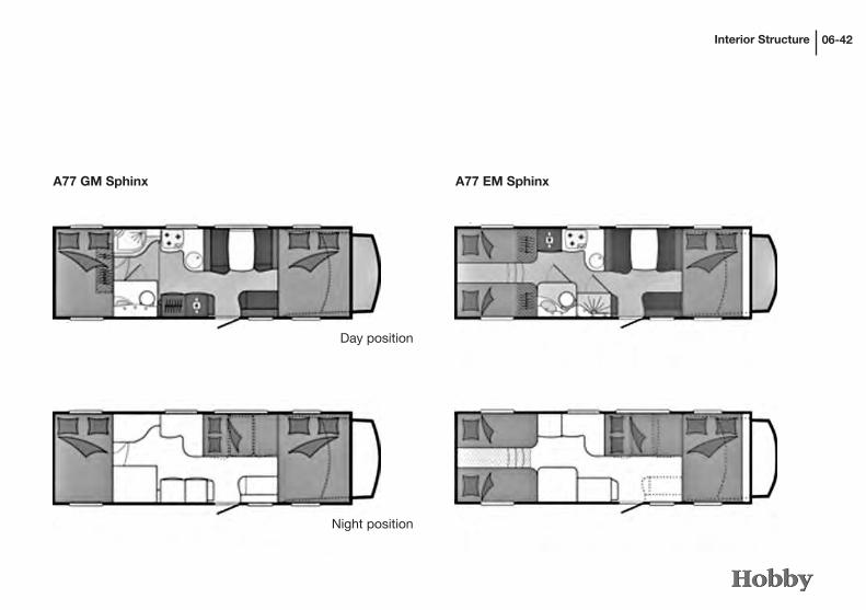
Interior Structure 06-42
A77 EM SphinxA77 GM Sphinx
Day position
Night position

Electrical Installations
Chapter 7: Electrical Installations
7.1 Safety instructions
The following must be observed:• Donot remove the signson electrical componentsgiving
safetyinstructionsordangerwarnings.• Donot use the installation compartments for the caravan
battery,on-boardcontrolpanel,batterychargerand230Vconnectorboxasadditionalstorageroom.
• Smoking and naked flame are forbiddenwhen checkingelectricalequipment.
• Onlyauthorisedandexperiencedworkshopsmaycarryoutelectricalrepairs.
• Inexperthandlingofthevehicle‘selectricalsystemmayen-dangeryourownlifeaswellasthatofothers.
• Useonlyweatherproof,3-wiredextensioncableandshock-proofplugorCEEplugandcouplerwhenhookinguptoanexternal230Vnetwork.
07-1
7.2 Elements of the electrical systemTheelectricpowersupplyisprovidedviatheHOBBYon-boardcontrolpanelinconnectionwithanautomaticbatterycharger.
Main elements of the electrical system• CONTROLPANEL– Controlstheelectricalconsumersandshowstheirstatus.• 12VDISTRIBUTIONMODULE- Mainrelay,batteryparallelrelay(12V–70A),refrigeratorrelay,pumprelay,chargingfacilityB1,safetyfuses.
• BATTERYCHARGINGDEVICE- Chargesthebatteryinbufferoperation• PROBEWITHRODS- Measuresthecontentsofthefreshwatertank•PROBEWITHSCREWS- LEDdisplayshowswhenwastewatertankisfull•MODULARBATTERY-WITHCIRCUITBREAKER Suppliesallelectricaldevices•VEHICLEBATTERY•GENERATOR- loadsboththevehicleandconsumerbatteriesatthesametime
•230VMAINSWITCH- suppliesandprotectsthe230Vconsumers•50AFUSESVEHICLE/andCONSUMERBATTERIES

Electrical Installations 07-2
Advice and instructions
Important• Anychangestotheelectricalinstallationsmayonlybecarriedoutbyaprofessionalelectrician.
• Disconnectthebatteryandswitchoffthe230Vmainsbeforecarryingoutanymaintenancework.
Batteries• Pleaseobservethebatterymanufacturer’soperatinginstruc-tions.
• Theacidinthebatteryispoisonousandcorrosive.Avoidcontactwitheyesandskin.
• Thecompletelydischargedbatterymustberechargedforatleast10hours.Thebatterymaybedamagedifithasbeendischargedformorethan8weeks.
• Avoidtotaldischargesincethissignificantlyreducestheper-formancecapacityandservicelifeofthebatteries.
• Checkthelevelofthebatteryfluidregularly(acidbatteries);gelbatteriesrequirenomaintenance,butmustbecontinuouslyrecharged.
• Checkthattheclampshavebeenproperlyfittedand,ifneces-sary,removeanylayersofoxide.
•Unclamptheminuspoleiftheancillarybatteryisnotbeingusedforalongerperiodoftime(morethan1-2months).Evenifthemainswitchofthebatteryhasbeeninterrupted,thebat-terymayberechargedbythecharger.(Conservationcharging)
• Shouldtheconsumerbatteryberemoved,isolatethepluspole(topreventshortcircuitswhenturningonthemotor).
Battery charger• Thecharger’scapacityis220W(VanExclusive) 300W(ToskanaExclusive,Sphinx).• ThechargerfunctionsinaccordancewithIU0U1chargingtechnology.
• Inthecaseofmisusetheguaranteeandmanufacturer’sliabilitywillnolongerapply.
• Donotpluguptheventilationandensurethatyouhaveade-quateventilation.
Tank probes• Toavoidincrustations,particularlyinthewastewatertank,neverletthewaterinthetanksstandfortoolong.Flushthetanksregularly.
230V main switch• Toswitchoffthepowersupplyfortheentiresystemsetthemainswitchto“0”(OFF).
•Connectanddisconnectthe230Vmainsconnectiononlywhenthemainswitchhasbeenswitchedoff.
Fuses• Onlyreplacedefectivefusesafterthecauseofthedefecthasbeenremediedbyaprofessionalelectrician.
• Thenewfusemusthavethesameamperageastheoldone.

Electrical Installations07-3
Control panel
Legend
jKeyformonitoringthebatteryvoltageofthesuperstruc-tureandthevehicle.
kKeyfordisplayingthelevelofliquidinthefreshwatertank[in%]andforsettingtheparametersthatcanbeprogrammed.
lKeyforprogrammingthesystem.
mMainswitch(pressforapprox.2sec.toturnonoroff).Whenyouswitchiton,thesystemwillcarryoutafunc-tionaltestandshowallofthesymbolsonthedisplay.Whenitisgreen,thecorrespondingLEDshowsthatthecontrolpanelison.Ifitisred,itshowsthatanalarmhasgoneoffsomewhere(battery,tank,etc.).
nKeyforturningthelightsandtheheatingonandoff.
oKeyforturningthefreshwaterpumponandoff.
pKeyforswitchingtheoutertentlightonandoff(theoutertentlightisautomaticallyswitchedoffwhenthemotoristurnedon).
1 2 3 4 5 6 7
Programming settings
Amongotherthings,thetimeandthealarmfunctioncanbesetintheprogrammingmenu(pleaserefertotheusermanualformorepossiblesettings).
-Pressthe"PROG"keyforlongerthan2sec.-Usethearrowkeys(1)and(2)tonavigate.-Use"PROG"toconfirmthesettingyouwishtoset.-Press"PROG"severaltimestosavesettingsandexitfromthemenu.
-Toexitwithoutsaving,waitapprox.20seconds.

Electrical Installations 07-4
Functions
Protection against total dischargeAnelectronicinstallationturnsoffall12Vconsumerswhentheconsumerbatteryreachesaminimumvoltageof10V.Thecon-sumerscanbeswitchedonagainforapprox.oneminutebyswitchingthemainswitchonagain.
Therefrigerator,electricentrancestepandthoseconsumersdirectlysuppliedbyB2arenotaffectedbythisinstallation.
1 2 4
13 14 15 16 17
10
11
3
12
98
7
5
6
Main display
j230Vmains
kChargedstateofthevehiclebatterylParallelconnectionofsuperstructureandvehiclebattery
mVehiclemotor
nOutsidetemperature
oInsidetemperature
pDigitalclock
qProgram
rTonesdeactivated
sAlarmclockdisplayON Consumptiondisplayforfreshwatertank Consumptiondisplayforbattery Freshwatertankempty Wastewatertankfull
11121314
Deepdischargeprotectionon Modularbatterybelowminimumvoltage Vehiclebatterybelowminimumvoltage
151617

Electrical Installations07-5
45123
Intelligent Battery Sensor (IBS) (Optional Extra)Asanoptionalfeature,yourvehicleisequippedwithabatterysensor.TheIBScontrolmeasurestheavailablecapacityofthebatteryandalsoindicatesbatteryageing.
LegendjDOD display Showstheremainingamountoftimeforuseifcurrent
amountofuseiscontinued..
kElectric power display Red=discharge Green=charge
lElectricity as a numerical value Example:Currentdischarge:0.1A.
mBattery ageing (SOH=StateofHealth) Example:Theoriginalcapacityofthebatteryhasalready
beenreducedby2%.
nState of charge (SOC=StateofCharge) Actualstateofchargeofthebattery Example:SOC:88%.

Electrical Installations 07-6
Distribution module
Fuses
j 10Afuseforsupplyofthefronttentlight
k 10Afuseforsupplyofthewaterpump
10
10 20 30 25 3
10 20 20 3
AUXB
A
1 3 5 7 9
2 4 6 8 10
-B2 +B2 +B1
1 2 3 4
1 2
1 4 7 01
2 5 8 11
3 6 9 21
1
9
8
16
1 4
2 5
3 6
1 4 7
2 5 8
3 6 9
12
20
19A
15
11
1413
1718
16
232221
12
A
B
19B
171819
141516
19
l 10Afuseforsupplyoftheheating/boiler
m 20Afuseforthelights
n 20Afuseforthelights
o 30Afuseforsupplyofthe12VAESabsorberrefrigerator
p 20Afusefortheauxsupply(solarchargercontroller)
q 25Afusesforsupplyoftheelectricstep
r 3Afuse
s 3Afuse Bridgecircuit SimulatedD+alternatoroutputforelectricstepand
refrigerator Change-overswitchmustbeinPosition“A” ElectricaldeviceconnectionA ElectricaldeviceconnectionB Electricaldeviceconnection Freshwatertanksensorconnection Freshwatertanksensorconnection ASignalinputignition-variationA BSignalinputignition-variationB Groundconnectionforelectricaldevices Connectionfornegativepoleformodularbattery Connectionforpositivepoleformodularbattery Connectionforpositivepoleformodularbattery
2021
2322
1112
13

Electrical Installations07-7
7.3 Electric power supply
Yourmotor homehas the following connections for electricpowersupply:- electricmains(a.c.voltage230V)- caravanbattery(d.c.voltage12V)
Supply via mains connectionThe230Vsystemissafeguardedbya2-polecircuitbrea-kerwitharesidualcurrentoperateddeviceand2x13A.Theresidualcurrentoperateddeviceislocatedeitherintheseatingarrangementbehindthedriver‘sseatorintheclothescupboard(dependingonthemodel).Shouldtherebeapowerfailure,theautomaticpersonprotectioncircuitinterruptstheentire230Velectriccircuit.Inmostcases,suchapowerfai-lureiscausedbyadefectelectricaldeviceoradefectcord.•Repairthedefectbeforeyouswitchthecircuitbreakeronagain.
•Ifyoucannotrepairthedefect,consultanelectrician.
Rules for the mains connection:• Useonlya3x2.5mm²cablewithamaximumlengthof 25m,aCEEplugandconnectortoconnectthemotorhometoanexternal230Vmains.
Ifyouareusingacabledrumwithoutprotectionagainstoverheating,theelectriccablemustbecompletelyunw-oundfromthecabledrum.
• UseonlyplugsandcablesthatmeetCEEstandards.• First,make the connection to themain socket (1) of the
vehicle.• Theninserttheotherpluginthelivesocket.• Followthissequenceinreversewhenyoupullouttheplug.

Electrical Installations 07-8
7.4 Functioning of the electrical supply unit
Place of installation of the battery chargerThebatterychargerislocatedunderthepassenger‘sseat(VanExclusive/Toskana/ToskanaExclusive)orinthesideseatingbenchbehindthepassenger‘sseat(Sphinx).
Operating the 230 V mains connectionAfterthemainsconnectionhasbeenpluggedin,boththemodularandthevehiclebatterywillautomaticallybechargedbythebatterychargerinthemotorhome(eveniftheControlPanelhasnotbeenswitchedon).
1
2
Exterior socket
Opening• Takeholdof thebottomof the cover flapj andpull it
upwards.
Closing• RemoveCEEplugk.• Pushcoverflapjdownuntilyouhearitlockintoplace.

Electrical Installations07-9
ItisnotnecessarytoswitchthemainswitchontheBoardControlPaneloninordertochargethebatteries.Whenthebatterychargerhasbeenswitchedon,thebatteriesarechar-gedassoonasthefeederplugsupplies230V.
Charging procedureThechargerrepresentsthecurrentstatusoftechnologyandchargesinthreephasesinaccordancewiththeso-calledIU0U1curve.Thechargingperiodshouldbeatleast12hours.
Function of the battery charger
Protecting the deviceIfthebatterychargershouldbecomehotbecauseofhighen-vironmentaltemperaturesorhighchargingcurrents,abuilt-inthermalswitchturnsoffthebatterychargeruntilthetemperatureinthebatterychargerhasdroppedagain.
Check list• Turnoffthemotor.• Connectthebatterychargertothemainssupply.• Switchonthe12Vmainswitch.• Turnoffallequipment(alsorefrigerator)using12Vpower.
Thevoltageof thecaravanbatterymust rise toamaximumvoltageof14.4V.
Batteriesdonotrespondwelltocoldtemperatures;insuchcasestheydonotsupplyelectricitytotheon-boardcircuitorabsorbpowerfromthecharger.Therefore,whentravellinginwinter,theheatingshouldbeturnedonbeforechargingthebatteries.
Thebatteryvoltageofboththemotorbatteryandtheancillarybatterycanbecheckedcontinuouslyonthecontrolpanel.
Thebatterychargeronlyworksifthebatterieshavebeeninsertedwiththeirpolesintherightdirection.
Theminimumchargingperiodof12hoursmustbeexten-dedaccordinglyifequipmentusing12Visswitchedonduringcharging.
Total discharge protectionIfthebatteryvoltageoftheancillarybatterysinksbelow10.5Varelayshutsdownallequipmentusingpower.
Ifthetotaldischargeprotectionisactivatedturnoffthe12Vmainswitchtoavoidanadditionaldischargeoftheancillarybattery.

Electrical Installations 07-10
Thevoltageofthecaravanbatterymustriseif- theenginespeedisabovetheidlingspeed,- thevehicle‘sbatteryisnotcompletelydischarged.
Thecontrolpanelshowswhetherornotthegeneratorhasbeencharged.Ifthisisnotthecase,pleasecheckthefollow-ing:
• Isthe50Afuseinthesupplylinetotheancillarybatterynearthemotorbatteryfunctioningproperly?
• Isthefusedistributionpaneldisplayingthe“Motorrun-ning”signal?
Operation by means of a 12 V caravan batteryAlloftheequipmentisautomaticallysuppliedfromthecara-vanbatteryifthemotorhomeisstandingstillwithouta230Vmainssupplyandwithitsengineturnedoff.The12Vmainswitchmustbeswitchedonandthebattery‘scircuitbreakermustbeclosed.
Thecaravanbatteryshouldonlybeallowedtodischargetoavoltageof11V.Atthispoint,youshouldensurethatitisrechargedfromthedynamoorfrompublicsupply.
Ifthisdoesnothappenafterusingthebuilt-inbatterychargertochargethebattery,checkthefollowing:• Isthechargerattachedcorrectlytothepowersupply?• Isthecharger’smainsfuseworkingproperly?• Isthecharger’sbatteryvoltageover3volts?• Aretheancillarybattery’spolesattachedcorrectly?
Operation when the motor is runningAssoonasthemotorisrunning,arelayconnectsthestarterbatteryandthecaravanbatteryinparallel.TheD+signalsitsclose to the dynamo. Therefore, the dynamo charges bothbatteries.IftheD+signalnolongersitsclosetothedynamo,thetwobatterieswillbeseparatedfromeachotheragain.Inthisway,thestarterbatterycannotbedischargedbyequipmentinthecaravan.The12Vsupplyfortherefrigeratoronlyfunctionswhenyouaredriving.Ifthemotorhasstopped,the12Voperationoftherefrigeratorisautomaticallyturnedoffagain.
Checklist• Turnoffthemotor.• Switchonthe12Vmasterswitch.
• Turnoffallequipmentthatuses12V.• Startthemotor.
To charge a discharged caravanbattery optimallywhiledriving,disconnectthe12Voperationoftherefrigeratorandturnoffasmuchequipmentaspossiblethatuses12V.

Electrical Installations07-11
Changing the battery• Pleasedonotsmokewhenchangingthebattery.• Disconnecttheconnectiontothe230Vnetwork.• Beforeyouconnectordisconnectthebattery,allofthe 12Velectricaldevicesmustbeswitchedoffandthebattery‘s
circuitbreakermustbeopened.
7.5 Caravan battery
Place of installation- VanExclusive/Toskana/ToskanaExclusive:underthepassenger‘sseat
- Sphinx:inthesideseatingarrangementbehindthepassenger‘sseat
Features- Thebatterydoesnotrequiremaintenance.Itdoesnotneed
toberefilledwithwater.- Thebatteryisclosedoffandcannotleak.- The battery is cycle-proof,making it especially suitable
forthesupplyoftheboardnetwork.Severaldischarging/chargingoperationsarepossible.
Useonlythesamekindofbatterieswhenexchangingthebattery(samecapacityandvoltage,cycle-proof,mainte-nance-freeandleakproof).
• First,disconnectthenegative(-)terminal.• Thendisconnectthepositive(+)terminal.• Removethebattery.• Insertthenewbattery.• Usethereversesequencetoconnectthenewbattery.

Electrical Installations 07-12
1
Circuit breakerToprotectthemodularbatteryfrombeingexhaustivelydischargedwhenthemotorhomeisnotbeingused,acircuitbreakerjhasbeeninstalled.Whenthisisopened,themo-dularbatteryiscompleteddisconnectedfromthe12Vmains.
1
Whenthecircuitbreakerisopen,theelectricalinputstagewillnotengageautomatically.
7.6 Fuse protection of the electric system
Ancillary batteryThemainfuseprotectioniscarriedoutbymeansofa50Asafetyfusej.Thefuseislocateddirectlynexttothebattery.
12V circuitsFuseprotectioniscarriedoutbymeansoffusesonthe12Vdistributionmodule.
The following applies if one of the devices breaks down• Checkthefuseonthecorrespondingelectriccircuit.• Replacethefuse.• Ifthefuseblowsagainpleasecontactyourauthorized
Hobbydealer.

Electrical Installations07-13
Charger with distribution module
Thechargerlanddistributionmodulekwithintegratedfusesarelocatedinfrontofthemodularbatteryunderthefrontpassengerseat.
32
7.7 Mobile navigation
Asanoptionalextra,yourmotorhomecanbeequippedwithanavigationsystemandintegratedrearviewcamera,whichcanbeclippedintoaspecialholderonthedashboard.Itthenfunctionsimmediately.
• Presstherightswitchjforward.• Firstremovetheright-handsideofthesat-navdevice,
thentheleft-handside.
1
1

Electrical Installations 07-14
•Removethedevicefromtheholderwhenyouparkyourmotorhome,asotherwiseitwillcontinuetouseelectri-cityandthestarterbatterymightbedischarged.
•Readthedevicemanufacturer‘soperatinginstructionscarefullybeforeinitialoperation.
•Donotallowyourselftobedistractedbythisdeviceasthismaycauseaccidents.
•Neveroperatethedevicewhiledriving.•Checkthedisplaypanelonlywhenthetrafficsituationissafefordoingso.
7.8 Subsequently installed devices
Subsequentlyinstalledelectronicdevicesthatcanbeusedwhiledriving(e.g.mobilephones,wirelessequipment,radios,came-rasfordrivinginreverse,navigationequipment,orothers)mustmeetalloftherequirementsforelectromagneticcompatibility.SuchequipmentmusthavebeenapprovedinaccordancewithEUGuideline72/245/EWGasitappearsinversion95/54/EG,becauseotherwiseitmaycauseinterferencewiththeelectronicsystemsalreadyinstalledinthemotorhome.
ACEmarkismandatoryfordevicesthathavebeensubsequent-lyinstalledandwhichcannotbeusedwhiledriving.
Information on how the TV works
•InordertousetheTV,thehandbrakemustbeon.•Toguaranteethattheantennasearchesforasatellitequicklyandcorrectly,pleaseensurethatnoobstacles(e.g.trees)obstructthesearch.

Water08-1
Chapter 8: WaterThe water supply system corresponds to the current sta-tus of technology as per 10/2009 [Directive 2002/72/EC].
The motor home is equipped with a fixed fresh water tank. An electric water pump pumps the water to the individual water outlets. When a tap is turned on the pump is automatically activated and pumps water to the relevant outlet. The waste water tank collects the dirty waste water. The water levels in the fresh water and waste water tanks can be checked on the control panel display.
The fresh water tank is filled using the filler neck on the side wall. The fresh water filler neck has a blue cap j and a tap symbol on the bottom edge of the frame. The filler cap j can be opened or closed using the ancillary key.
Filling the system• Close all outlets and valves.• Open the protective cover k of the filler neck by pulling it.• Unlock and open the filler cap j.• Fill the tank with drinking water.• Switch on the 12V main switch.• If applicable turn on the water pump at the control panel.
8.2 Water supply
8.1 General
• Always use water that is of drinkable quality when wor-king with food. This also applies for washing your hands or objects that come into contact with food.
• In order to ensure excellent water quality, water should be taken directly from the public drinking water system.
• Garden hoses, watering cans and similar materials unsu-itable for drinking water should never be used to fill the mobile system.
• If the motor home has not been used for a longer period of time, the entire water system must be emptied com-pletely.
• After longer periods of stagnation, the water system must be flushed thoroughly before being used. Should you discover impurities, the material should be disin-fected using suitable agents that have been approved for such measures.

Water
1
2
08-2
Emptying the fresh water tank• The outlet valve j is located next to the fresh water tank
in the seating arrangement on the outside wall (Van Exclu-sive / Toskana Exclusive).
• In the Sphinx models, the outlet valve can be accessed above the rear external storage locker (rear left service flap).
1
Always empty the fresh water tank completely if the hea-ting has not been switched on and the motor home is not in use, and especially if there is frost.
Always ensure that the fresh water tank is filled before switching on the pump. The pump can be destroyed if allowed to run dry!
Never introduce anti-freeze or other chemicals into the wa-ter system. This can be poisonous! When operating during winter ensure that the fresh water tank is sufficiently heated.
• Turn all taps to “warm”; let the water run and wait until the water runs without bubbles. This is the only way to ensure that the warm water boiler is also filled with water.
The fresh water tanks in the following models: D 69 H GFLC with a technically permissible maximum weight of 4000 kg have been equipped with an overflow valve that limits the volume of fresh water to 10 l. Before driving, the overflow valve must be opened.

Water08-3
Attach hand showers to the shower fitting. Check that water is draining out. Clean the tanks and rinse them thoroughly. Allow the water system to dry for as long as possible. Do not forget to empty the toilet cassette.
If the vehicle is not being used and there is a danger of sub-zero temperatures be sure to drain the entire water system. Leave taps turn on in the middle position. Leave all drain valves open.
Only empty your waste water tank at the specially desi-gnated disposal points and never in open spaces! As a rule disposal points can be found at motorway service stations; campsites and petrol stations.
Waste water tankIn the Van Exclusive and Toskana Exclusive models, the waste water tank is insulated by a Styrofoam casing that hot air flows through (only when the hot-air heating has been turned on). This prevents the waste water from freezing in a light frost.
In the Sphinx models, the waste water tank has been in-stalled in the heated false ceiling, which efficiently prevents the waste water from freezing.
Draining the water systemEnsure that the motor home is in a horizontal position. Turn off the 12 V power supply at the control panel. Turn on all drain cocks. If possible open the filler cap of the fresh water tank. Turn the water taps to the middle position and let them run.
Do a small quantity of antifreeze agent (e.g. table salt) to the waste water tank if temperatures are significantly below freezing to prevent the waste water from freezing.
The waste water tank is not sufficiently protected against damage from frost when the vehicle is not in use. Therefore, if there is any danger of sub-zero temperatures empty the waste water tank completely.
Never pour boiling water down the sink. This can cause distortions and leaks in the waste water system.
The waste water heating cartridge can only be switched on when the motor home is connected to the 230V mains supply.
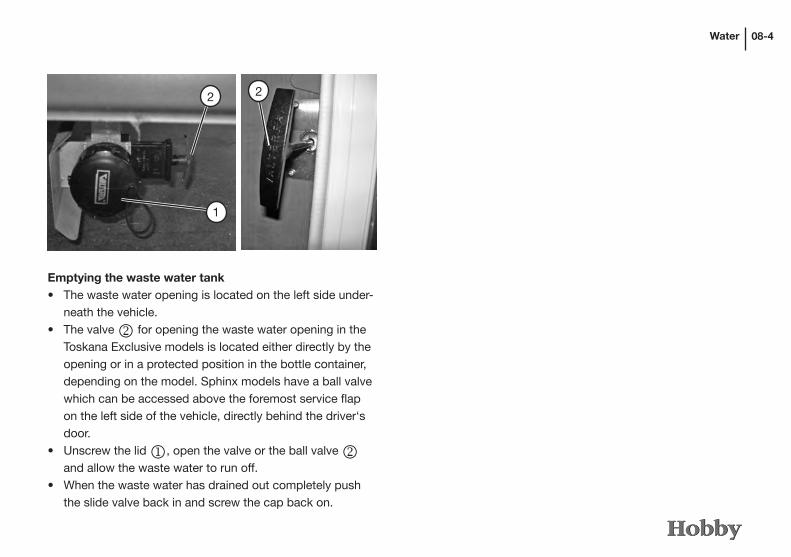
Water 08-4
Emptying the waste water tank• The waste water opening is located on the left side under-
neath the vehicle.• The valve k for opening the waste water opening in the
Toskana Exclusive models is located either directly by the opening or in a protected position in the bottle container, depending on the model. Sphinx models have a ball valve which can be accessed above the foremost service flap on the left side of the vehicle, directly behind the driver‘s door.
• Unscrew the lid j, open the valve or the ball valve k and allow the waste water to run off.
• When the waste water has drained out completely push the slide valve back in and screw the cap back on.
1
22

Water08-5
8.4 Flushing toilet
Preparing the toilet• Open the Thetford door (see 5.1) and pull the holding bar
up to remove the waste tank.
The waste tank can only be removed when the drain valve is closed.
• Pull out the tank as far as possible, keeping it level.• Slightly tip the waste tank and then pull it out completely.• Place it in an upright vertical position.• Turn the drain nozzle to an upward position.
8.3 Hot water supply
Your motor home is equipped with a heating system with integrated boiler. The boiler holds 10 litres of water. During summer use the water can be heated independently of the heating system. Please see Chapter 9.3 Heating for instruc-tions on operating the boiler.
The non-electric safety or drain valve will automatically open at temperatures under approx. 3°C and drain the boiler contents via a drain nozzle.
If the cold water system is operated without the boiler the boiler tank will still fill with water. In order to avoid frost damage the boiler must be drained via the drain valve, even when not in use.

Water 08-6
• Fill the waste tank with the correct amount of toilet fluids.• Then add enough water to completely cover the bottom of
the waste tank.• Return the drain nozzle to its original position.
Use toilet fluids very sparingly. An overdose is no guaran-tee of preventing possible odours!
• Push the waste tank back into position.• Ensure that the holding bar secures the waste tank.• Close the service flap.
Never fill toilet fluids directly into the toilet bowl.

Water08-7
Emptying the waste tankThe waste tank must be emptied at the latest when the LED lights up. It is recommended that the tank is emptied before this. The LED lights up when the tank contains more than 15 litres. From this point in time the tank has a residual capacity of 2 litres, representing approx. 5 flushes.
• Open the toilet flap and pull the holding bar up to remove the waste tank.
The waste tank can only be removed when the drain valve is closed.
Using the toilet• Turn the toilet bowl to a comfortable position.• Fill the toilet bowl with a small amount of water by pres-
sing the flush button or by opening the drain valve by pulling the valve handle under the toilet bowl towards you.
• Use the toilet.• After use open the drain valve (if still closed) and flush.
Close the drain valve after flushing.

Water
2
1
08-8
Only empty the waste tank at specially designated dis-posal points and never in open spaces!
• Take the waste tank to a designated disposal site, making sure to hold the drain nozzle in an upright position.• Remove the cap on the drain nozzle.• Tilt the waste tank so that the drain nozzle is pointing
downwards.• Press the vent button with your thumb and hold it down.
The waste tank will drain itself.• Return the waste tank to its storage position, ensuring
that it is pushed in until the holding bar locks into place.• Lock the service flap.
Water connection for external shower (Optional Extra)
Opening• Push the cover j up to gain access to the water connection.
Closing• Remove the external shower’s hose from the connection
point k and attach the protective cover.• Push the cover down.

Gas09-1
Chapter 9: Gas
9.1 General safety rules when using LPG fittings
If you suspect that gas is leaking, take the following measures immediately:
• Close the stop valve on the gas cylinder.• Ignition sources such as open flames or smoking are strictly forbidden.• Air the rooms.• Clear the danger zone.• Inform your immediate surroundings (groundsman) and, if necessary, the fire brigade.
The gas fittings may only be taken into operation again after they have been checked by an expert.
Built-in objects and changes• Objects may only be built in and changes to the gas fit-
tings made by an expert.• Only devices with a constant connection pressure of 30
mbar may be operated.• Following any changes to the gas fittings they must be
rechecked by a recognised expert, who must provide a written confirmation.
Checkingthegasfittings• Before initial operation have the LPG fittings checked by
an expert.• The gas fittings must be checked every 2 years by an LPG
expert. This must be confirmed on the certificate (in ac-cordance with Form G 607 from the German Association of Gas and Water Experts (DVGW) and EN 1949).
• The regulator and waste gas pipes must also be checked.• We recommend that you replace the safety regulator at
least every 6 years.• The connecting hose should also be checked regularly for
damage. Replace it immediately if you find tears, porous spots or similar damage.
• The operator is responsible for having checks carried out.
You are not permitted to operate the heating system while driving!Exception:As an optional feature, the vehicle can be equipped with a gas pressure regulator for use while driving (e.g. Control CS, SecuMotion).

Gas 09-2
Regulators and valves• Use only special vehicle regulators that have a safety
valve. In accordance with the German DVWG (German As-sociation of the Gas and Water Sector) Worksheet G 607, other regulators are not permitted; they are not adequate for handling the heavy strain.
• Pressure governors must have a fixed pressure of 30 mbar. The regulations of EN 12864, Appendix D apply ac-cordingly. The pressure governors must have a minimum flow rate of 1.2 hx/h.
• Attach the high-pressure hose on the bottle carefully by hand (note: left-handed thread). Do not use spanners, pliers or similar tools.
• If the temperature is below 5°C use the de-frosting facility (ice-ex) for regulators.
The operating pressure for gas is 30 mbar.
Before initial operation• The waste gas pipe must be tightly connected to the hea-
ting and chimney without any leaks. It may not be dama-ged.
• Keep vents clear.• Remove any snow from the chimney.• Clear aspirating openings for combustion air in the side
all from dirt and/or snow. Otherwise, the exhaust fumes could have a CO content higher than allowed.
• Do not close the safety vents.• We recommend that you store a Type D (dry powder)
fire extinguisher with a minimum capacity of 1 kg by the entrance door as well as a fire blanket next to the cooker. Familiarize yourself with the safety precautions against fire that have been set up on the grounds where you are parked.
Read the manufacturer’s operating manuals carefully!
Never use portable cooking or heating devices, except electrical heating devices - but no radiant heaters, because they can cause danger of fire and suffocation.

Gas09-3
9.2 Gas supplyThe motor home is equipped with a propane gas system (gas bottle not included in scope of delivery). This system is used to run the following equipment:- Cooker- Refrigerator- Heating- Hot water boiler- Oven- Possibly special accessories
Gas bottle cabinetDepending on the model access to the gas bottle cabinet is either via the rear storage compartment or separately in the side wall.
The gas bottle cabinet holds 2 x 11 kg propane gas cylinders.
The gas bottle container holds two 11 kg propane cylinders j. Via a safety regulator k , the gas bottles are attached by a hose l to the supply line m . Each bottle is fastened by two separate belts n to the wall at the front end of the camper or the floor of the gas bottle container.
5 1
2
4 3
Gas bottles may only be carried in the gas bottle container.

Gas 09-4
The following applies to the gas bottle cabinet:• Always check the gas cylinder mountings before driving.
Stand the gas cylinders upright and close the valves.• Pull any loose straps tight.• The high-pressure hose to the cylinders must be checked
for leaks using the leak detector every time a cylinder is changed.
• The gas bottle cabinet is not suitable for storing additional items.
• The stop valves on the gas cylinders must always be easily accessible.• Do not close the gas bottle cabinet’s air vents.• Ensure that third parties cannot gain access to the gas
bottle cabinet.
Gas bottles must be shut while driving.
Gas regulator for France and Great BritainDue to specific country regulations, the gas regulator in vehicles exported to France and Great Britain is mounted on the wall of the gas bottle container. The requires the use of a high-pressure hose. Therefore, the low-pressure hoses that are normally used may not be fitted here.
- gas regulator mounted on the wall j - high-pressure hose k
1
2
This must be taken into account should it be necessary to replace the hose.

Gas09-5
• Open the door of the gas bottle cabinet.• Close the main stop valve on the gas cylinder. Pay attenti-
on to the direction of the arrow.• Unscrew the gas pressure regulator with the gas hose by
hand from the gas bottle (left-handed thread).• Loosen the fixing strap and remove the gas cylinder.• Replace the full gas cylinder in the gas bottle cabinet and
carefully fasten it using the fixing straps.• Screw the gas pressure regulator with the gas hose by
hand on to the gas bottle (left-handed thread).• Check that gas is not escaping from the connection point
using leak detector spray.• Close the gas bottle cabinet door.
Do not smoke or ignite open flames while changing the gas cylinders. After changing the gas bottles, check whether there is any gas escaping from the tie-in point by spraying it with leak detection spray.
Gas stop valvesEvery gas device is fitted with a corresponding gas stop valve. The gas stop valves are located in the kitchen drawer above the cutlery tray and are labelled with the corresponding symbols.
Changing gas cylinders

Gas 09-6
The following applies to stop valves and valves:• All the valves on gas devices must be closed while driving. • The photos above show the shutoff valves when they
are closed. To open the valves, they must be turned to a vertical position.
• No firing point may be in operation when filling the petrol tank of your vehicle on ferries or in the garage.
Over the years, vibrations can cause slight leakages to occur. If you suspect that there are leakages, have your dealer or an authorised workshop for gas facilities check your system.
Never carry out leak tests near an open flame.
Heating (Oven) Gas cooker Refrigerator
Should you suspect a leak in the gas system, immediately close the shutoff valves in the vehicle and the gas bottle valves in the gas bottle container.

Gas09-7
Gas regulator with a crash sensor (Optional Extra)
Using the MonoControl CS, it is possible to heat the vehicle even while driving.
Should there be an accident, the integrated crash sensor automatically interrupts the gas supply, thereby preventing gas from escaping.(Effect of delay 3.5 g ± 0.5 g; this corresponds to an impact speed of 15-20 km/h against a fixed obstacle.)
To operatej Open the valve on the bottle.
k Press firmly on the hose rupture protection (green button) on the high-pressure hose.
l If necessary (e.g. after it has been newly mounted or the gas bottle accidentally hits against the gas pressure regulator system) press the green reset button on the MonoControl CS (resets the crash sensor activation
element).
12
3

Gas 09-8
Changing a gas bottle
• Open the door of the gas bottle container.• Close the main shutoff valve on the gas bottle, noting the
direction of the arrow.• Unscrew the high-pressure hose from the gas bottle.• Release the fastening straps and take out the gas bottle.• Place a full gas bottle back in the gas bottle container and
use both fastening straps to lash it securely.• Screw the high-pressure hose to the full gas bottle.• Open the valve on the full gas bottle.• Press the hose rupture protection (see: To operate)• Check whether there is any gas escaping from the tie-in
points by spraying them with leak detection spray.• Close the door of the gas bottle container.
Please use the enclosed screw aid to screw and unscrew the hose. It ensures the necessary tightening torque.
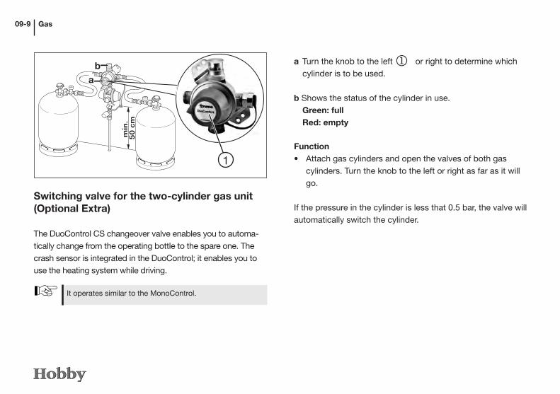
Gas09-9
Switching valve for the two-cylinder gas unit (Optional Extra)
The DuoControl CS changeover valve enables you to automa-tically change from the operating bottle to the spare one. The crash sensor is integrated in the DuoControl; it enables you to use the heating system while driving.
a Turn the knob to the left j or right to determine which cylinder is to be used.
b Shows the status of the cylinder in use. Green: full Red: empty
1
DuoComfort
min
. 5
0 c
m
b
a
ba
Function• Attach gas cylinders and open the valves of both gas
cylinders. Turn the knob to the left or right as far as it will go.
If the pressure in the cylinder is less that 0.5 bar, the valve will automatically switch the cylinder.
It operates similar to the MonoControl.
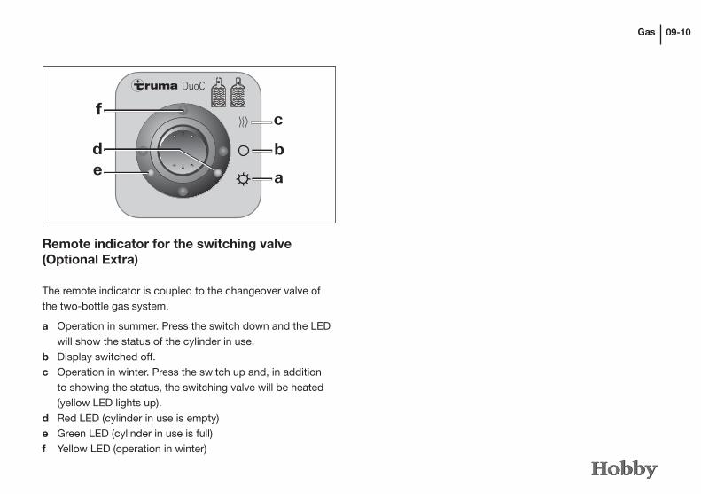
Gas 09-10
Remote indicator for the switching valve (Optional Extra)
The remote indicator is coupled to the changeover valve of the two-bottle gas system.
a Operation in summer. Press the switch down and the LED will show the status of the cylinder in use.b Display switched off.c Operation in winter. Press the switch up and, in addition to showing the status, the switching valve will be heated (yellow LED lights up).d Red LED (cylinder in use is empty)e Green LED (cylinder in use is full)f Yellow LED (operation in winter)
DuoC
f
bde
c
a

Built-in devices10-1
Chapter 10: Built-in devices
10.1 General Information
Please also refer to the instructions in Chapter 9 for opera-ting gas devices, gas regulators and gas bottles.
Built-in devices may only be repaired by specialists.
In this chapter, you will find information on the devices that have been built into the motor home. This information refers only to the operation of these devices. To some extent, the devices described are special accessories. For further infor-mation on the individual built-in devices, please refer to the separate operating instructions that have been included in the blue service bag found in the vehicle.
Only the device manufacturer's original spare parts may be used for maintenance and repair work.
Any changes to the built-in devices as well as non-com-pliance with the rules for use will cause the guarantee to become void and lead to the exclusion of liability claims. Furthermore, the operating licence for the device will become void and, in some countries, this means that the operating licence for the vehicle is also void.
Please observe the instructions in Chapter 7 for operating electrical devices.

Built-in devices 10-2
10.2 Heating
The combined LPG heating consists of a warm air heater with an integrated hot water boiler (capacity: 10 l).The heating system is fully operational with or without the hot water system.
Initial operation• Set the air vents in the motor home so that the warm air is blown out where required.• Check that the chimney is clear. Remove any covers.• Open the gas cylinder and the gas stop valve.
Operating panela Rotary switch for room temperature (1-5)b green LED lights up: “ON” green LED flashes: “COAST DOWN” to reduce the heater’s temperature.
1
3
57
9
40°
60°
60°
Combi
1
23
45
c
df
b
ag, h
e
c Summer operation (Water temperature 40°C or 60°C)d Winter operation (Heating without regulated water temperature or with drained water system)e Winter operation (Heating with regulated water temperature)f Rotary switch “OFF”g Yellow LED lights up: “BOILER HEAT-UP PHASE”h Red LED lights up, red LED flashes “MALFUNCTION”: carefully clean the heater’s rotary switch with a brush.

Built-in devices10-3
k
m
n
o
FrostControl
FrostControl is a non-electric safety or drain valve. If there is a risk of sub-zero temperatures it automatically drains the content of the boiler via a drain outlet.If the system is under excess pressure intermittent pressure equalisation will automatically take place via the safety valve. The outlet valve is located by the heating connection in your vehicle.k Rotary switch position “ON”m Push button position “CLOSED”n Push button position “DRAIN”o Drain outlet (to the outside through the vehicle floor)
To activate• Push in the knob at position (m) slightly and, at the same time, move it 90° towards position (k).• If the switch is in position (k), the knob will remain in posi- tion (m).
To deactivate• Turn the switch at position (k) by 90° so that it is parallel to the frost control.• At the same time, the knob will jump from position (m) to position (n).
The drain valve can only be closed manually using the push button (Position m) and the boiler filled if the valve temperature is above approx. 7°C.
If the temperature of the safety/drain valve is lower than approx. 3°C, the push button will be ejected (Po-sition n) and the contents of the boiler will be drained off via the drain outlet (o).

Built-in devices 10-4
1
3
57
9
40°
60°
60°
Combi
1
23
45
c
df
b
ag, h
e
1
3
57
9
40°
60°
60°
Combi
1
23
45
c
df
b
ag, h
e
Summer operation
• Turn the rotary switch on the operating panel to Position c (summer operation 40°C or 60°C). The green (b) and yellow (g) LEDs will light up. When the water temperature selected (40°C or 60°C) has been reached, the burner will turn off and the yellow LED (g) will go out.
Winter operation
Heating with regulated water temperature • Set the rotary switch to operating position (e). • Turn the rotary button (a) to the desired thermostat setting (1-5). The green LED (b) for operation lights up and simultane ously displays the setting for the room temperature selected.
The yellow LED (g) indicates the warming up phase for the water. The device will automatically select the perfor-mance level required. When the room temperature set on the operating panel has been reached the burner will

Built-in devices10-5
Heating without regulated water temperature• Set the rotary switch to operating position (d).• Turn the rotary button (a) to the desired thermostat setting
(1-5).
The green LED (b) for operation lights up and simulta-neously displays the setting for the room temperature selected. The yellow LED (g – warming-up phase for the water) only lights up at water temperatures below 5°C. The device will automatically select the performance level required.
When the room temperature set on the operating panel has been reached the burner will turn off. The warm air blower will continue to run at a low rotation speed as long as the air emission temperature (of the device) is above 40°C. If the boiler is full the water will automatically also be heated. The water temperature will depend on the heat produced and the duration of heating required to reach the room temperature selected.
revert back to the lowest setting and heat the water in the boiler to 60° C. The yellow LED (g) will go out when the water temperature has been reached.
Heating with drained water system• Set the rotary switch to operating position (d).• Turn the rotary button (a) to the desired thermostat setting (1-5).
The green LED (b) for operation lights up and simultane-ously displays the setting for the room temperature se-lected. The yellow LED (g) only lights up if the temperature of the device is below 5°C. The device will automatically select the performance level required.When the room temperature set on the operating panel has been reached the burner will turn off.

Built-in devices 10-6
Turning off• Turn the heater off using the rotary switch (position f). The green LED (b) will go out.
If the green LED (b) flashes after the device has been turned off, a coast-down phase to reduce the device’s temperature is being carried out. This will finish after a few minutes and the green LED (b) will go out.
In the case of malfunction, the red LED (h) will light up. Please check the manufacturer`s instructions to determine possibble causes of malfunction.
Filling up the boiler• Close the drain valve by pushing the button until it locks into place.• Turn on the 12V power supply by turning on the main switch on the control panel.• Turn on all taps and set them to “warm”. Leave them on until the boiler fills up due to the air displacement.
At temperatures below approx. 7°C turn on the heating first in order to warm up the installation area and the FrostControl on the drain valve. After a few minutes, when the temperature on the FrostControl is above 7°C, the drain valve can be closed.
Draining the boiler• Turn off the 12V power supply at the control panel.• Turn on the hot water taps.• Turn the rotary switch on the drain valve 180° until it locks into place (the push button will be ejected), the drain valve will open and the boiler contents will drain off to outside.

Built-in devices10-7
10.3 Electric Heating System (Optional Extra)
The electric heating system also has heating rods to enable electric operation. These can be switched on or combined manually.
a Rotary switch for selecting type of energyb Electrical operation: 230 V, 1800 Wc Electrical operation: 230 V, 900 Wd Operating on gase Mixed operation* (gas and electrical operation, 900 W)f Mixed operation* (gas and electrical operation, 1800 W)g Yellow LED lit up: "Electrical operation"
*For operation in winter only!When operating in summer, the device automatically selects electrical operation with the preselected electric power(900 W or 1800 W).
Combi E
230 V~
ed
f
g
bca

Built-in devices 10-8
10.4 Hot-water heating (Optional Extra)
The LPG heating system Compact 3010 is a hot-water hea-ting system with a separate hot-water heater (contents: 8.5 l). The heating system can heat up even if the hot-water heater has not been filled with fresh water.
Place of installation- in the clothes cupboard
Frischwasser aus
Glykolflüssigkeit Ausgang zu den Heizkörpern
Steuerkarte
Brennerlüfter
Luftzufuhr
Abgasauslass
Magnetventil
Glykolflüssigkeit Eingang Rücklauf
Frischwasser ein
Elektrische Heizpatrone 1 kW
Elektrische Heizpatrone 2 kW
Please note the following• Please read the separate operating instructions carefully
before initial use of the heating system.• Always switch the main switch for the heating system off
whenever the vehicle is not in use.• If there is danger of frost, always empty the fresh water out
of the hot-water heater.• The heating system may not be started if it has not been
filled with glycol.• To make the best possible use of the convection principle,
nothing must prevent the air from circulating in the motor home, such as behind the back cushions, winter ventilati-on, in the bed frames and behind the stowage cabinets.

Built-in devices10-9
Operating methods- LPG operation- heating cartridge operation (230 V)- combined LPG and heating cartridge operation
Functionality- hot-water heater- heating system and hot-water heater- heating system
Operating unitWhile on standby, you can see which functions have been activated for the heating system; the backlight is switched off. After two minutes, the operating unit switches from the setting position to standby if no key is pressed or if the arrow keys have been used to set it to standby.
To start the hot water heaterPress the On/Off button. The heater will start, using the settings that were last selected. The Alde logo appears on the display.
Please refer to the separate operating instructions for the „Alde Compact 3010“ for more detailed information on the operation, use and upkeep of the hot-water heater.
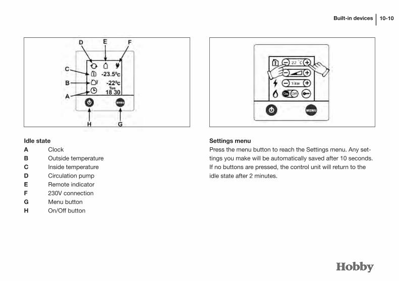
Built-in devices 10-10
Idle stateA ClockB Outside temperatureC Inside temperatureD Circulation pumpE Remote indicatorF 230V connectionG Menu buttonH On/Off button
Settings menuPress the menu button to reach the Settings menu. Any set-tings you make will be automatically saved after 10 seconds. If no buttons are pressed, the control unit will return to the
idle state after 2 minutes.

Built-in devices10-11
Setting the desired temperature(+5°C to +30°C) by pressing – or + in steps of 0.5°C.
Hot water (50°C) is always available when this is switched on. The hot-water system is operated electrically or uses LPG.
Setting the hot waterShould you require more hot water, the temperature can be increased temporarily from 50°C to 65°C. After 30 minutes, the hot-water heater will switch back to normal operation. Increase the amount by pressing +; turn the hot water off by pressing -.
Setting the electric heating systemUse the – and + buttons to select the output (Off, 1/2/3 kW). Preference is given to electrical operation when selecting whether to operate on electricity or gas.
Setting for heating with gas Set the heating to gas operation. Start operation with gas by pressing the On button. The heating system will operate until the temperature you have set has been reached. Turn gas operation off by pressing the Off button.
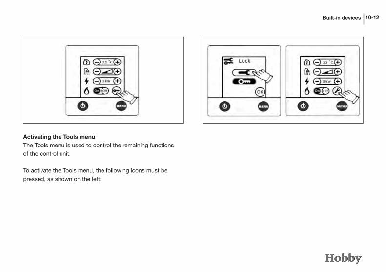
Built-in devices 10-12
Activating the Tools menuThe Tools menu is used to control the remaining functions of the control unit.
To activate the Tools menu, the following icons must be pressed, as shown on the left:

Built-in devices10-13
Functions of the Tools menu 1 Arrow icons enabling you to switch between the indivi-
dual Tools fields.2 Setting the clock to use functions such as automatic
start or automatic temperature.3 Automatic temperature change to set temperatures,
e.g. at night or on individual days.4 Automatic start at a later time. The heating system will
run for 24 hours and repeats this procedure every week at the same time. The On/Off button must be set to Off.
5 Overload protection prevents 230V fuses from overloa-ding. If power consumption exceeds the value that has been set, the electric output of the heating system will automatically be reduced.

Built-in devices 10-14
1 Continuous operation of the pumps to limit the volume of hot water, especially if little heating is required.
2 Pump Auto / 12V – the 230V pump will run if this is set to the auto position; if the 230V electric power supply is interrupted, the 12V pump will start up. If set to 12V, the 12V pump will run even if the 230V electric power supply has been connected.
3 Setting the pump speed.4 This function is used in combination with the automa-
tic gas-bottle change-over (DuoComfort). It indicates
whether the liquid gas bottle is empty.
1 Temperature setting for calibrating the temperature using the control unit.
2 Automatic increase in temperature at 2.00 a.m. to r educe danger of Legionella bacteria.3 Language setting (German, English, French)
4 Function for external start, e.g. using GSM.
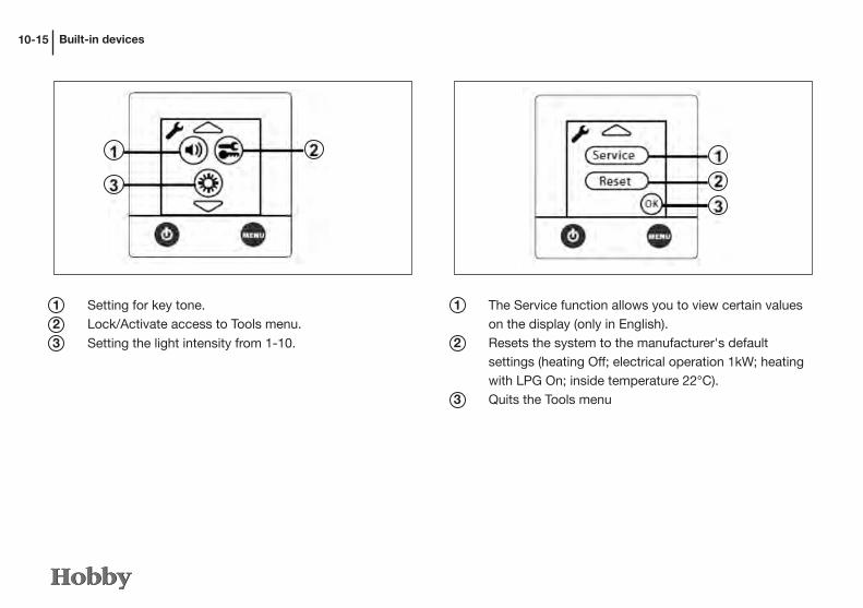
Built-in devices10-15
1 Setting for key tone.2 Lock/Activate access to Tools menu.
3 Setting the light intensity from 1-10.
1 The Service function allows you to view certain values on the display (only in English).
2 Resets the system to the manufacturer's default settings (heating Off; electrical operation 1kW; heating with LPG On; inside temperature 22°C).
3 Quits the Tools menu

Built-in devices 10-16
Error messages Error messages are shown on the display (panel in idle state).
Battery low: if voltage sinks to under 10.5V, the heating system will switch off. Automatic reset to above 11V.
Fan failure: incorrect fan speed. Automatic reset after 5 minutes.
Gas failure: gas bottle is empty. Reset by switching off or restart.
Overheating is red: to reset, interrupt the 12V electric power supply and connect it again.
Overheating is blue: to reset, interrupt the 12V electric power supply and connect it again.
Window is open: the heating system interrupts the gas supply when thewindow is open. Shut the window.
Connection failure: connection error between the heating system and the panel. Switch the main voltage off and then on again.
Panel failure 1: panel errorPanel failure 2: panel error

Built-in devices10-17
10.5 Auxiliary Heating in the Driver's Cab (Optional Extra)
This heating unit is integrated in the water circuit; electric power is supplied by means of the 12V modular battery.
FunctionThe heating function is set manually using the switch in the driver's cab.
Set the switch to position j to heat the driver's cab.
Set the switch to position k if you prefer to heat the motor; this will, however, also preheat the interior.
1
2
Please refer to the separate operating instructions for the „Alde Compact 3010“ for more detailed information on the operation, use and upkeep of the hot-water heater.
1
Wash roomSince the convector heater in the wash room must be moun-ted behind the external panel and, therefore, there is no gu-arantee that the air can circulate sufficiently, a fan has been provided to circulate the hot air in the room. This fan can be activated in two stages using the switch j.

Built-in devices 10-18
12 V operation12 V operation can only be used while driving, when the mo-tor is running. When resting or if you have stopped for a lon-ger period of time, turn off the 12 V operation and, if required, select another mode of operation.
• Turn the energy selector switch to battery operation j.• 12V operation will only function if the vehicle’s motor is
running.• The refrigerator runs without a thermostatic control (con-
tinuous operation). 12 V operation should, therefore, only serve to maintain a temperature which has already been achieved.
1
2
3
10.6 Refrigerator
Modes of operationThree modes of operation are possible for the refrigerator.- 12 V operation: electricity is supplied by the motor
home’s battery.- 230 V operation: electricity is supplied from an external
source.- LPG: supply is from the motor home’s gas bottles
Please refer to the manufacturer's separate operating instructions before using the refrigerator.
10.5 Auxiliary Heating in the Driver's Cab (Optional Extra)

Built-in devices10-19
The refrigerator door must always be kept closed and locked while driving.
Refrigerator door lock
Lock on the Tec Tower Lock on the Slim Tower
To open the refrigerator door, press down on the button j There is an automatic lock on the door of the refrigerator. When you shut the refrigerator door and press it firmly, it will lock itself automatically. The lock on the freezer compartment is the same as the one on the refrigerator. It is located under-neath the freezer door k.
1
2
• To turn the refrigerator off turn the energy selector switch to the O position.
230 V operation• Turn the energy selector switch to mains k.• Set the temperature using the thermostat.• To turn the refrigerator off turn the energy selector switch
to the O position.
Gas operation• Turn the energy selector switch to gas operation l.• Open the main stop valve on the gas cylinder and the
“Refrigerator” gas stop valve. • Turn the thermostat to the highest setting and keep it
pressed down. The refrigerator will either automatically ignite or by pressing the button for manual ignition (de-pending on the model).
• When the pilot light has ignited, let go of the thermostat. Repeat the previous step if there has not been ignition.
• Set the cooling temperature using the thermostat.• To turn the refrigerator off turn the energy selector switch
to the O position• Close the main stop valve on the gas cylinder and the
“Refrigerator” gas stop valve.

Built-in devices 10-20
To remove the freezer• Fold down the locking clamps underneath the freezer.• Push both clamps towards the middle.• Pull the freezer slightly out.• Unhinge the door.• Remove the floor panel of the freezer.
To avoid mould or unpleasant odours always lock the refrigerator door in the ventilation position when the refri-gerator is turned off.
Removable freezer (Slim Tower)
To make the best use of space, the freezer can be removed.
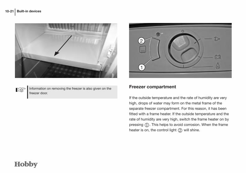
Built-in devices10-21
Freezer compartment
If the outside temperature and the rate of humidity are very high, drops of water may form on the metal frame of the separate freezer compartment. For this reason, it has been fitted with a frame heater. If the outside temperature and the rate of humidity are very high, switch the frame heater on by pressing j. This helps to avoid corrosion. When the frame heater is on, the control light k will shine.
1
2
Information on removing the freezer is also given on the freezer door.

Built-in devices 10-22
Do not operate the cooker when the glass covering is closed.
Never use the cooker or other devices extracting combu-stion air from the interior of the vehicle to heat the vehicle. If this is ignored there is an acute risk to life due to a lack of oxygen and the odourless carbon monoxide which could be generated.
10.7 Gas cooker
The kitchen in the motor home is equipped with a gas cooker with three burners.
Before initial operation• Open the bottle valve and the quick-action stop valve in
the gas pipe.• Open the skylight or the kitchen window• Ignition points which must be pressed for ignition when
turning on the gas device should spring back to their original position after being pressed.

Built-in devices10-23
Use oven gloves or potholders when handling hot pots, pans or similar objects. You may be burned!
Never store easily flammable objects such as dishtowels, serviettes, etc. near the cooker. Danger of fire!
• To turn off the gas flame, turn the rotary switch back to the “0” position
• Close the main gas stop valve on the gas cooker.
After cooking, leave the glass covering open until the burner no longer emits heat. Otherwise, the glass plate could explode.
2
1
Operation• Open the tinted glass covering j.• Turn the rotary switch k of the burner you wish to use to
the ignition position (large flame) and press.• Ignite the burner with a gas lighter or a match or cigarette
lighter.• Continue to press the rotary switch for a further 5-10
seconds to ensure that the automatic flame guard takes effect.
• Release the rotary switch k and turn to the desired set-ting (large or small flame).
• If ignition was unsuccessful, repeat the procedure.

Built-in devices 10-24
• Never operate the oven when it is empty (no food inside).• Never use the grill (Optional Extra) for longer than 25 minutes.• Never use the oven to heat the motor home.
Switching on• Turn on the 12 V power supply at the main switch of the
control panel.• Open the main stop valve on the gas cylinder and the gas
stop valve “Oven”.• Open the oven door as far as it will go.• Position the oven rack or baking tray in such a way that
there is no direct contact with the flame.• Gently press the rotary switch and set it to the desired
ignition position (oven or grill).• Press the rotary switch. Gas will be released to the burner
and the flame will ignite automatically.• Depress the rotary switch for a few seconds until the igniti-
on safety valve keeps the gas supply open.• Release the rotary switch and set it to the desired level of
performance (oven only).• Close the oven door carefully so that the flame is not extin-
guished.
10.8 Oven (Optional Extra)
• Do not close the air vents on the oven.• Only use the oven after making a 230 V or 12 V mains
connection (automatic ignition).• A skylight or window must be open when the oven is in
operation.• The oven door must remain open during the ignition
process.• If there is no ignition repeat the procedure from the be-
ginning.• In the event the pilot light is extinguished by mistake set
the rotary switch to the “0” position and leave the pilot light out for at least one minute before reigniting it.

Built-in devices10-23
10.9 Fume Hood (Optional Extra)
The built-in fan blows kitchen odours directly outside.
Clean the filter of the fume hood regularly, as it collects fat from kitchen odours.
j Light
k To switch on
l To set the speed for the fan
1 2 3
Switching off • Turn the rotary switch to the “0” position. The flame will be
extinguished.• Close the main stop valve on the gas cylinder and the gas
stop valve “Oven”.

Built-in devices 10-24
To set the direction of ventilation• First turn the knob counter-clockwise.• Set the slide to correspond with the desired direction of
ventilation.• Turn the knob clockwise.
10.10 Rooftop Air Conditioning (Optional Extra)
The air conditioner is located instead of the roof window on the living room ceiling.To operate the air conditioner correctly and optimize its per-formance, you should observe the following:
• Ensure sound thermal insulation; seal chinks and cover up glass areas.
• Avoid opening doors and windows unnecessarily.• Do not plug or cover up air intakes and openings.• Do not spray water into the air conditioner.• Keep all easily inflammable material away from the system.

Maintenance and Care11-1
Chapter 11: Maintenance andCare
11.1 Maintenance
Maintenance intervals
There are stipulated maintenance intervals for the motor home
and its equipment.
Also note the maintenance intervals for the basic Fiat vehicle.
11.2 Airing
For a comfortable climate inside the caravan, there must be sufficient ventilation. This also avoids corrosive damage due to condensation.
Condensation is caused by- insufficient volume inside the caravan- breathing and perspiration of the passengers- bringing in damp clothing- operating a gas cooker
Ensure that there is a sufficient exchange of air to avoid damages due to the build-up of condensation!
The following applies for maintenance intervals:• Have the first maintenance carried out by a HOBBY dealer
12 months after the vehicle was first registered.• All further maintenance should be carried out once a year
by a HOBBY dealer.• The maintenance of the basic vehicle as well as all built-in
equipment should be carried out at the intervals given in each operating manual.
The gas fittings must be checked every 2 years by an expert for LPG and confirmed on the certificate in accor-dance with DVGW G 607 and EN 1949.
The operator of the vehicle is responsible for having main-tenance carried out on schedule.
Replace the safety regulator for gas at least every 6 years!
For safety reasons, spare parts for equipment must conform with the manufacturer‘s instructions and must be installed by him or a duly authorised representative.

Maintenance and Care 11-2
11.3 Care
Cleaning the exteriorThe vehicle should not be washed more often than necessary.
Wash the vehicle only in places provided for this purpose.
Using cleaning materials sparingly. Aggressive cleansers, such as wheel rim cleaners, damage the environment.
The following applies when cleaning the exterior:• Rinse the vehicle with a weak jet of water.• Wash the vehicle with a soft sponge and a commercial
shampoo solution. Rinse the sponge often.• Then rinse with a generous amount of water.• Dry the vehicle with a suede cloth.• After washing the vehicle, leave it standing outside to dry
off completely.
Dry the headlights and sockets thoroughly, as water collects
there easily.
Only wash the vehicle at sites designated for this pur-pose. Avoid direct exposure to sunlight and adhere to environmental protection measures.Do not use cleaning agents containing solvents.
Washing with a high pressure cleaner
Do not spray stickers and external decors directly with the high pressure cleaner as they could peel away as a result.
Before washing the motor home with a high pressure cleaner, study its operating manual carefully. During washing maintain a minimum distance of 700 mm between the motor home and the high pressure cleaner. Please note that the water jet is under pressure when it comes out of the cleaning nozzle. Incorrect handling of the high pressure cleaner can result in damage to the motor home. The water temperature should not exceed 60°C. Keep the water jet moving while washing. The jet should not be pointed directly at gaps around doors; gaps around windows; acrylic windows; electric attachments; the exhaust chimney; refrigerator grille; connectors; seals; service flaps or skylights as this could damage the vehicle or result in water penetrating inside the vehicle.

Maintenance and Care
The following applies for damages:• Repair damages immediately to avoid further damages due
to corrosion. Ask your HOBBY dealer for assistance.
Skylights, windows and doorsWindow panes require particularly careful treatment.
The following applies for their care:• Rub the rubber seals around doors and windows lightly
with talcum powder.• Clean acrylic glass panes only with a clean, wet sponge
and a soft cloth. Cleaning with a dry cloth may scratch the panes.
11-3
The following applies when waxing the surfaces:• The varnished surfaces should be treated occasionally
with wax. Follow the application instructions given by the wax manufacturers.
The following applies when polishing the surfaces:• In exceptional cases, use polish to refinish weathered
varnished surfaces. We recommend solvent-free polishing paste.
Use polish only in special cases and as seldom as possible, because polish removes the top layer of varnish. Frequent polishing causes extreme wear.
The following applies for tar and resin stains:• Tar and resin stains as well as other organic stains can be
removed with petroleum ether or spirits.
Do not use aggressive solutions such as products contai-ning ester or ketone.
Do not use strong and aggressive solutions that contain softeners or solvents!
You will find talcum powder in auto accessory shops.

Maintenance and Care 11-4
We recommend the following methods for cleaning:Method A: • Use only commercial cleaning agents that have a water
basis.• Alternatively, add two tablespoons of ammonia to 1 litre. Dip a cloth into this solution and gently sponge the spot. Turn the cloth over so that you are using a clean cloth to touch the spot. This method is particularly suitable for removing:- wine, milk, lemonade- blood- biro, ink- urine, sweat- mud- vomit
Method B: • Use only mild, water-free solvents for dry cleaning.• Dampen the cloth and proceed as described in method A.
This method is particularly suitable for removing:- wax, candles- pencil
The following applies for cushions, upholstery and curtains:• Clean cushions with a soft brush or hoover. • Have very dirty upholstery and curtains dry-cleaned. Do
not wash them yourself!• If necessary, wash them carefully using the foam from
mild-action detergent.
Cleaning the interior
To reduce problems arising from dampness, use water sparingly when cleaning inside.
Cleaning instructions for materials that containTeflon(Dubai and Devon)
• Always treat spots immediately.• Sponge spots, but do not rub them.• Work from the edge towards the middle of the spot.• Never use household cleaners to remove spots.• Hoover cushions regularly to remove any dirt that may
have collected.

Maintenance and Care11-5
The following applies for furniture surfaces:• Clean the surface of wooden furniture with a damp cloth or
sponge.• Rub dry with a dust-free cloth.• Use mild furniture polish.
Never use strong cleansers or intensive furniture polish, because this could scratch the surface!
The following applies for the toilet:• Clean with a neutral liquid cleanser and a cloth that does
not scratch.
Never use strong cleansers in the toilet!
Do not use diluted acetic acid to clean the toilet and the water system or for descaling the water system. Diluted acetic acid can damage the seals or parts of the system.
Do not pour any corrosive substances down the drains. Do not pour boiling water down the drains. Corrosive substances and boiling water damage drain pipes and syphons.
The following applies for the sink and the cooker:• Clean stainless steel parts with normal household cleaners
or special stainless steel cleansing agents.
The following applies for carpeted floors:• Clean with a hoover or brush.• If necessary, treat with carpet shampoo or a shampooing
machine.
The following applies for the PVC flooring:
Sand and dust can damage the surface of PVC flooring that is walked on regularly. When in use, clean the floor daily with a Hoover or a broom.
• Use cleansing agents for PVC floors and clean water when washing the floor. Do not place fitted carpets on a wet PVC floor, as the fitted carpet and the PVC flooring could become glued together.
• Never use chemical cleansing agents or steel wool, be-cause this will damage the PVC flooring.
Chocolate or coffee should only be washed out with luke-warm water.
Maintenance and Care 11-6
Accessories
The following applies for their care:• Clean plastic parts (e.g. fenders, skirts) with water of up to
60° C and mild household cleansers.• Clean greasy or oily surfaces with spirits.• If necessary, lubricate door hinges and leveling supports.• Clean fresh water pipes, the fresh water and waste water
tanks once a year.
Do not use strong cleansers, because these could scratch the surface!
Remove all spray cans containing cleansing and care so-lutions from the vehicle after you have finished! Otherwise they may explode if the temperature exceeds 50° C!
11.4 Winter Lay Up for the Motor home
The camping season often ends when winter starts. Your motor home must be prepared accordingly before being laid up for the winter.
It should only be left in a closed space if this is dry and easy to air well. Otherwise, it is better to leave your motor home in the open.
The following applies for the base vehicle and the exter-nal superstructure:
• Preserve varnished external surfaces with suitable agents.• Use a wax-based protective agent to protect the metal
parts of the undercarriage against rust.• To protect the tires, jack up the motor home and move it
every two months.• Leave space between tarpaulins and the motor home so
as not to hamper ventilation.• Leave the forced ventilation open.• Air the motor home thoroughly every three to four weeks.• Check the antifreezer in the cooling system and, if necessary, top it up.
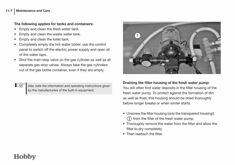
Maintenance and Care11-7
Draining the filter housing of the fresh water pump:You will often find water deposits in the filter housing of thefresh water pump. To protect against the formation of dirtas well as frost, this housing should be dried thoroughly before longer breaks or when winter starts.
• Unscrew the filter housing (only the transparent housing!)
j from the filter of the fresh water pump.• Thoroughly remove the water from the filter and allow the
filter to dry completely.• Then reattach the filter.
1
The following applies for tanks and containers:• Empty and clean the fresh water tank.• Empty and clean the waste water tank.• Empty and clean the toilet tank.• Completely empty the hot-water boiler: use the control
panel to switch off the electric power supply and open all of the water taps.
• Shut the main stop valve on the gas cylinder as well as all separate gas stop valves. Always take the gas cylinders out of the gas bottle container, even if they are empty.
Also note the information and operating instructions given by the manufacturers of the built-in equipment.

Maintenance and Care 11-8
The following applies for the interior fittings: • Empty and clean the refrigerator; leave the refrigerator
door open.• Leave stowage spaces and cupboards open to enable air
circulation.• Place cushions and mattresses in such a way that they do
not come into contact with condensation.• If necessary, heat the motor home to prevent the build-up
of mould from condensation.• Set up a dehumidifier (such as salt) inside the camper and
dry the granulate or change it regularly.• Open the battery's circuit breaker. Ideally, remove the bat-
tery and/or check the charge level approx. once a month; if necessary, recharge it.
• Switch off the main switch for 12V.

Maintenance and Care11-7
If, despite all of these measures, condensation forms, simply wipe it away.
The following applies for your preparations:• Check the vehicle for damage to the paintwork or from
rust and, if necessary, repair it.• Ensure that water cannot run into the ventilation and de-
aerating and heating systems.• Use a wax-based protective agent to protect the metal
parts of the undercarriage against rust.• Preserve varnished external surfaces with suitable agents.• Fill the petrol tank with winter diesel; check the antifreezer
in the windshield cleaning unit and the coolant.
IDuring operation in winter, condensation is caused when using the camper in low temperatures. Sufficient ventilation is extremely important to ensure that the quality of the air inside the camper is good and to avoid damages to the vehicle caused by condensation.
11.5 Winter Operation
Preparations Your motor home has been designed to allow you to use it to a certain extent in winter. If you really wish to camp in winter, we recommend that you optimize your motor home to meet your personal requirements. Your dealer will be pleased to advise you.
The following applies for ventilation:• Set the heating to maximum power when heating up the
vehicle and open all of the upper cupboards, curtains and shades/screens. This enables you to achieve optimum ventilation and de-aerating.
• Every morning, air all of the cushions and stowage spaces and dry any damp spots.
• Air thoroughly with fully opened doors and windows sever-al times a day.
• If the outside temperature is under 8° C, winter covers should be mounted over the ventilation grilles of the refri-gerator.
Before entering the vehicle, remove the snow from your clothes and shoes to prevent an increase in humidity.
The following applies for heating: • Both the air intake as well as the exhaust gas openings of
the heating system must be kept free of snow and ice.• It takes longer to heat up the motor home in winter, especially to heat hot water.
Maintenance and Care 11-8
If there is danger of frost, or if you are in the vehicle, you must let the heating run during the night!
Check the gas supply when operating the vehicle in win-ter: up to three times as much gas is used.
The following applies for tanks and containers:• If the interior is sufficiently heated, the fresh water tank,
water pipes and therme/boiler should not freeze. Fill all of the water containers only after the interior has been
thoroughly heated.• Since waste water is collected outside the vehicle, add
antifreezer or common salt to it. The drain cock of the sewage pipe must be kept clear.
• The toilet can be used normally, even in cold weather, as long as the interior of the motor home is heated. If there is a danger of frost, both the excrement and the flushing water tanks should be emptied.
• Do not let the interior cool down completely when you are away or at night; set the heating to low and leave it on.
At the end of the winter season
The following applies for the care of the vehicle:• Thoroughly wash the underbody and the motor. This removes
corrosive thawing agents (salts, alkali).• Clean the exterior and use normal car wax to preserve metal
parts.• Do not forget to remove flue extensions, cover panels on
refrigerators, etc.
Wash the vehicle only in places provided for this purpose.
Using cleaning materials sparingly. Aggressive cleansers, such as wheel rim cleaners, damage the environment.

Sanitation and Environmental Protection12-1
Chapter 12: Sanitation and Environmental Protection
12.1 The environment and traveling
Environmentally fair useIt is only natural that owners of motor homes and caravans have a special responsibility for the environment. Always use your vehicle in an environmentally friendly way. The following applies for environmentally fair use:
• Whenspendinglongerperiodsintownsandcitiesaskaboutspeciallydesignatedcampsitesformotorhomesand use them.
• Donotspoilthepeaceandcleanlinessofnature.• Disposeofwastwaterandrubbishintheproperway.• Setanexamplesothatmotorhomeandcaravandriversare
notgenerallyheldtobepollutionists.

Sanitation and Environmental Protection 12-2
The following applies for wastes:• Onlyuseapprovedsanitarycleansingproductsinthewaste
tank.
The following applies for waste water:• Collectwastewateronboardonly inbuilt-inwastewater
tanksor,ifnecessary,insuitablecontainers!• Never empty waste water in open spaces or down man-
holes!Generally, thepublicwastewater systemdoesnot
runthroughclarificationplants.
• Emptyyourwastewatertankasoftenaspossible,evenifitis
notcompletelyfull(hygiene).Ifpossible,rinseoutthewaste
watertankwithfreshwaterafteremptying.
Only empty yourwastewater tank in special places forwastewaterdisposal,butneverinopenspaces!Generally,wastewaterstationsarefoundinmotorwayserviceareas,campsites or petrol stations.
You may be able to avoid the use of sanitary liquids by installing an activated carbon filter system (sold as anaccessory)!
Usesanitaryliquidsverysparingly.Anoverdoseisnogua-ranteeofpreventingodours!

Sanitation and Environmental Protection12-3
The following applies for waste:• Separateyourwasteandputappropriatematerials inthe
recyclingbins.• Emptywastebinsasoftenaspossible intheappropriate
bins or containers. This avoids unpleasant and problematic wastefrombuildinguponboard.
The following applies for picnic spots:• Alwaysleavepicnicspotscleanandtidy,evenifyoudispose
of someone else‘s waste.
Carefuluseoftheenvironment isnotonly inthe interestof nature, but also ofmotor home and caravandriverseverywhere!
Sanitation• Neverallowthewastetanktobecometoofull.Emptythe
tankimmediatelyassoonasthelevelindicatorlightsup.• Never emptywastes downmanholes!Generally, the pu-
blicwastewatersystemdoesnotrunthroughclarification
plants.
Emptythewastetankinspecialplacesforsanitarydisposal,butneverinopenspaces!

Sanitation and Environmental Protection 12-4
12.2 Returning the vehicle
Ifyoushouldeverhavetogiveupyourmotorhomeandhaveitrecycled,themanufacturerofthebasicvehicleisresponsiblefortakingitback(statusatthetimeofprinting).
ThismeansthatyourHOBBYmotorhomewillbetakenbackfreeofchargebyanyFiatdealerandexpertlyrecycled.

Technical Data13-1
Chapter 13: Technical Data13.1 Weights according to 92/21/EWG
These figures refer to the standard vehicle without extra equipment. Deviations of up to 5 % are possible.
Model
Series
Weight of basic
vehicle
Driver
Diesel [kg]
Basic equipment
Mass when vehicle is ready to
start
Techn. perm.
overall weight
Overload weight
No. of seats
Conven- tioal
loading
Overload weight
Length of vehicle
Personal equipment
Remaining overload weight
DL 500 GESC Limited Edition - Van Exclusive 2775 75 77 110 3037 3500 463 4 225 238 6,9 109 129
D 650 ESC Limited Edition - Toskana 2750 75 77 110 3012 3500 488 4 225 263 7,0 110 153
60 ES Van Exclusive 2803 75 77 110 3065 3500 435 4 225 210 7,3 113 97
60 KL Van Exclusive 2865 75 77 110 3127 3500 373 4 225 148 7,3 113 35
69 GL Toskana Exclusive 2955 75 77 110 3217 3500 283 3 150 133 7,5 105 28
69 EL Toskana Exclusive 2962 75 77 110 3224 3500 276 3 150 126 7,5 105 21
69 QS Toskana Exclusive 2957 75 77 110 3219 3500 281 3 150 131 7,5 105 26
H69 GL Toskana Exclusive 3103 75 77 110 3365 4250 885 4 225 660 7,5 115 545
75 FL Toskana Exclusive 3437 75 77 110 3699 4500 801 4 225 576 8,0 120 456
75 TL Toskana Exclusive 3454 75 77 110 3716 4500 784 4 225 559 8,0 120 439
H75 FL Toskana Exclusive 3542 75 77 110 3804 4500 696 4 225 471 8,0 120 351
H75 UC Toskana Exclusive 3575 75 77 110 3837 4500 663 3 150 513 8,0 110 403
A77 EM Sphinx 3855 75 85 200 4215 5200 985 4 225 760 8,0 120 640
A77 GM Sphinx 3837 75 85 200 4197 5200 1003 4 225 778 8,0 120 658

Technical Data 13-2
Model
Series
Weight of basic
vehicle
Driver
Diesel [kg]
Basic equipment
Mass when vehicle is ready to
start
Techn. perm.
overall weight
Overload weight
No. of seats
Conven- tioal
loading
Overload weight
Length of vehicle
Personal equipment
Remaining overload weight
DL 500 GESC Limited Edition - Van Exclusive 2775 75 77 110 3037 3500 463 4 225 238 6,9 109 129
D 650 ESC Limited Edition - Toskana 2750 75 77 110 3012 3500 488 4 225 263 7,0 110 153
60 ES Van Exclusive 2803 75 77 110 3065 3500 435 4 225 210 7,3 113 97
60 KL Van Exclusive 2865 75 77 110 3127 3500 373 4 225 148 7,3 113 35
69 GL Toskana Exclusive 2955 75 77 110 3217 3500 283 3 150 133 7,5 105 28
69 EL Toskana Exclusive 2962 75 77 110 3224 3500 276 3 150 126 7,5 105 21
69 QS Toskana Exclusive 2957 75 77 110 3219 3500 281 3 150 131 7,5 105 26
H69 GL Toskana Exclusive 3103 75 77 110 3365 4250 885 4 225 660 7,5 115 545
75 FL Toskana Exclusive 3437 75 77 110 3699 4500 801 4 225 576 8,0 120 456
75 TL Toskana Exclusive 3454 75 77 110 3716 4500 784 4 225 559 8,0 120 439
H75 FL Toskana Exclusive 3542 75 77 110 3804 4500 696 4 225 471 8,0 120 351
H75 UC Toskana Exclusive 3575 75 77 110 3837 4500 663 3 150 513 8,0 110 403
A77 EM Sphinx 3855 75 85 200 4215 5200 985 4 225 760 8,0 120 640
A77 GM Sphinx 3837 75 85 200 4197 5200 1003 4 225 778 8,0 120 658
13.2 Inflation pressures
* These tire pressures are only valid for standard tires made by alter-native manufacturers (e.g. Continental, Pirelli, etc.).
Models with dual wheels (Iveco base vehicle) have an extension to make it easier to pump up the rear inner tires.
Motor homes
Tyres Tyre pressure (bar) Basis
Michelin XC Camping
215/70 R 15 C front: 5,0 rear: 5,5 FIAT
225/75 R 16 C front: 5,5 rear: 5,5 FIAT
other tyre manufacturers*
195/75 R 16 C front: 4,75 rear: 4,75 IVECO
215/70 R 15 C front: 4,1 rear: 4,5 FIAT
225/75 R 16 C front: 4,5 rear: 5,0 FIAT

Technical Data13-3
13.3 Technical data
Hobby Model Type Base Motorisation5) exhaust gas
emissions
Chassis Frame extension Tow-barModel vehicle Model Towing bracket Spherical head
FIAT Ducato X250 (front wheel drive)
DL 500 GESC Limited Edit. - Van Exclusive F3 Ducato 130 Multijet (95,5 kW) Euro 4 Spezial 205817 lowered SAWIKO 30PEI20011-P Typ 04 (3009000400)
D 650 ESC Limited Edit. - Toskana F3 Ducato 130 Multijet (95,5 kW) Euro 4 Spezial 205806 straight SAWIKO 30PEI20018-P Typ 04 (3009000400)
60 ES Van Exclusive F3 Ducato 115 Multijet (85 kW) Euro 5 Spezial 206457 lowered SAWIKO 30PEI20019-P Typ 04 (3009000400)
60 KL Van Exclusive F3 Ducato 115 Multijet (85 kW) Euro 5 Spezial 206854 straight SAWIKO 30PEI20019-P Typ 04 (3009000400)
69 GL Toskana Exclusive F3 Ducato 130 Multijet (96 kW) Euro 5 Spezial 205724 lowered SAWIKO 30PEI20010-P Typ 04 (3009000400)
69 EL Toskana Exclusive F3 Ducato 130 Multijet (96 kW) Euro 5 Spezial 205724 lowered SAWIKO 30PEI20010-P Typ 04 (3009000400)
69 QS Toskana Exclusive F3 Ducato 130 Multijet (96 kW) Euro 5 Spezial 205724 lowered SAWIKO 30PEI20010-P Typ 04 (3009000400)
H69 GL Toskana Exclusive F3 Ducato Maxi 130 Multijet (96 kW) Euro 5 Spezial 205724 lowered SAWIKO 30PEI20010-P Typ 04 (3009000400)
75 FL Toskana Exclusive F4 Ducato Maxi 130 Multijet (96 kW) Euro 5 AL-KO AMC 45HT straight AL-KO AMC58G-A ---
75 TL Toskana Exclusive F4 Ducato Maxi 130 Multijet (96 kW) Euro 5 AL-KO AMC 45HT straight AL-KO AMC58G-A ---
H75 FL Toskana Exclusive F4 Ducato Maxi 130 Multijet (96 kW) Euro 5 AL-KO AMC 45HT straight AL-KO AMC58G-A ---
H75 UC Toskana Exclusive F4 Ducato Maxi 130 Multijet (96 kW) Euro 5 AL-KO AMC 45HT straight AL-KO AMC58G-A ---
IVECO Daily (rear wheel drive)
A77 EM Sphinx J1 50 C 17 3.0 Twin Turbo EEV (125 kW) Euro V Ladder-type chassis frame 2059398) lowered BOSAL 7605-G ---
A77 GM Sphinx J1 50 C 17 3.0 Twin Turbo EEV (125 kW) Euro V Ladder-type chassis frame 2059398) lowered BOSAL 7605-G ---
All measurements in [mm] all weights in [kg] 2) without wing mirror, without side blinker3) tow coupling is a special accessory4) rear edge of traction unit to rear edge of back wall5) FIAT: 115 Multijet: 85 kW (115 PS); 130 Multijet: 96 kW (130 PS); 150 Multijet: 109 kW (148 PS); 180 Multijet Power 130 kW (177 PS)IVECO 3.0 170 PS (125 kW) Twin Turbo EEV (Euro V)
7) 4th seat on the right (1473034) is an option8) If special accessory has been ordered: pneumatic suspension 205940 (A77)

Technical Data 13-4
Hobby Model Type Base Motorisation5) exhaust gas
emissions
Chassis Frame extension Tow-barModel vehicle Model Towing bracket Spherical head
FIAT Ducato X250 (front wheel drive)
DL 500 GESC Limited Edit. - Van Exclusive F3 Ducato 130 Multijet (95,5 kW) Euro 4 Spezial 205817 lowered SAWIKO 30PEI20011-P Typ 04 (3009000400)
D 650 ESC Limited Edit. - Toskana F3 Ducato 130 Multijet (95,5 kW) Euro 4 Spezial 205806 straight SAWIKO 30PEI20018-P Typ 04 (3009000400)
60 ES Van Exclusive F3 Ducato 115 Multijet (85 kW) Euro 5 Spezial 206457 lowered SAWIKO 30PEI20019-P Typ 04 (3009000400)
60 KL Van Exclusive F3 Ducato 115 Multijet (85 kW) Euro 5 Spezial 206854 straight SAWIKO 30PEI20019-P Typ 04 (3009000400)
69 GL Toskana Exclusive F3 Ducato 130 Multijet (96 kW) Euro 5 Spezial 205724 lowered SAWIKO 30PEI20010-P Typ 04 (3009000400)
69 EL Toskana Exclusive F3 Ducato 130 Multijet (96 kW) Euro 5 Spezial 205724 lowered SAWIKO 30PEI20010-P Typ 04 (3009000400)
69 QS Toskana Exclusive F3 Ducato 130 Multijet (96 kW) Euro 5 Spezial 205724 lowered SAWIKO 30PEI20010-P Typ 04 (3009000400)
H69 GL Toskana Exclusive F3 Ducato Maxi 130 Multijet (96 kW) Euro 5 Spezial 205724 lowered SAWIKO 30PEI20010-P Typ 04 (3009000400)
75 FL Toskana Exclusive F4 Ducato Maxi 130 Multijet (96 kW) Euro 5 AL-KO AMC 45HT straight AL-KO AMC58G-A ---
75 TL Toskana Exclusive F4 Ducato Maxi 130 Multijet (96 kW) Euro 5 AL-KO AMC 45HT straight AL-KO AMC58G-A ---
H75 FL Toskana Exclusive F4 Ducato Maxi 130 Multijet (96 kW) Euro 5 AL-KO AMC 45HT straight AL-KO AMC58G-A ---
H75 UC Toskana Exclusive F4 Ducato Maxi 130 Multijet (96 kW) Euro 5 AL-KO AMC 45HT straight AL-KO AMC58G-A ---
IVECO Daily (rear wheel drive)
A77 EM Sphinx J1 50 C 17 3.0 Twin Turbo EEV (125 kW) Euro V Ladder-type chassis frame 2059398) lowered BOSAL 7605-G ---
A77 GM Sphinx J1 50 C 17 3.0 Twin Turbo EEV (125 kW) Euro V Ladder-type chassis frame 2059398) lowered BOSAL 7605-G ---
Belt Seats t.p.o.w. [kg]
Permiss. front axle
load
Permiss. rear axle
load
Unbrakedtrailer load3)
Brakedtrailer load3)
Maximumtowing weight
Length of super-
structure4)
Total Height Width Front treadwidth
Rear treadwidth
Wheel Front Rearsystem length1) 2) base projection projection
FIAT Ducato X250 (front wheel drive)
UAP 370 (20-10006904) 4 3500 1850 2000 750 1600 5100 4382 6947 2740 2240 1810 1790 3800 948 2199
UAP 371 (20-10006943) 4 3500 1850 2000 750 1600 5100 4527 6968 2870 2330 1810 1980 3800 948 2220
UAP 370 (20-10006904) 4 3500 1850 2000 750 1600 5100 4711 7276 2740 2240 1810 1790 4035 948 2293
UAP 370 (20-10006904) 4 3500 1850 2000 750 1600 5100 4711 7276 2740 2240 1810 1790 4035 948 2293
UAP 372 (20-10007347) 3 3500 1850 2000 750 1600 5100 5024 7465 2870 2310 1810 1790 4035 948 2482
UAP 371 (20-10006943) 3 3500 1850 2000 750 1600 5100 5024 7465 2870 2310 1810 1790 4035 948 2482
UAP 371 (20-10006943) 3 3500 1850 2000 750 1600 5100 5024 7465 2870 2310 1810 1790 4035 948 2482
UAP 372 (20-10007347) 4 4250 2100 2400 750 1600 5600 5024 7465 2952 2310 1810 1790 4035 948 2482
UAP 242 (20-10006947) 4 4500 2100 2x1500 750 1550 6000 5606 8047 2910 2310 1810 1860 4316 948 1983
UAP 241 (20-10006946) 4 4500 2100 2x1500 750 1550 6000 5606 8047 2910 2310 1810 1860 4316 948 1983
UAP 242 (20-10006947) 4 4500 2100 2x1500 750 1550 6000 5606 8047 2965 2310 1810 1860 4316 948 1983
AL-KO SGS5 1473024 ES re. 37) 4500 2100 2x1500 750 1550 6000 5606 8047 2965 2310 1810 1860 4316 948 1983
IVECO Daily (rear wheel drive)
UVP 150 (20-10005303) 4 5200 2100 3700 750 3000 8200 5515 8028 3290 2300 1812 1541 4750 998 2280
UVP 150 (20-10005303) 4 5200 2100 3700 750 3000 8200 5515 8028 3290 2300 1812 1541 4750 998 2280

Technical Data13-5
Load increased for Motorhomes
Hobby Model Type Base Seats t.p.o.w.[kg]
Permissible front axle
load
Permiss. rear axle
load
Unbrakedtrailer load3)
Brakedtrailer load3)
Maximumtowing weightModel vehicle
FIAT Ducato X250 (front wheel drive)
DL 500 GESC Limited Edit. - Van Exclusive F3 --- --- --- --- --- --- --- ---
D 650 ESC Limited Edit. - Toskana F3 --- --- --- --- --- --- --- ---
60 ES Van Exclusive F3 Ducato 4 3650 1850 2000 750 1600 5250
60 ES Van Exclusive F3 Ducato Maxi 4 4250 2100 2400 750 1600 5850
60 KL Van Exclusive F3 Ducato 4 3650 1850 2000 750 1600 5250
60 KL Van Exclusive F3 Ducato Maxi 4 4250 2100 2400 750 1600 5850
69 GL Toskana Exclusive F3 Ducato 4 3650 1850 2000 750 1600 5250
69 GL Toskana Exclusive F3 Ducato Maxi 4 4250 2100 2400 750 1600 5850
69 EL Toskana Exclusive F3 Ducato 4 3650 1850 2000 750 1600 5250
69 EL Toskana Exclusive F3 Ducato Maxi 4 4250 2100 2400 750 1600 5850
69 QS Toskana Exclusive F3 Ducato 4 3650 1850 2000 750 1600 5250
69 QS Toskana Exclusive F3 Ducato Maxi 4 4250 2100 2400 750 1600 5850
H69 GL Toskana Exclusive F3 --- --- --- --- --- --- --- ---
75 FL Toskana Exclusive F4 Ducato Maxi 4 5000 2100 2x1500 750 1550 6000
75 TL Toskana Exclusive F4 Ducato Maxi 4 5000 2100 2x1500 750 1550 6000
H75 FL Toskana Exclusive F4 Ducato Maxi 4 5000 2100 2x1500 750 1550 6000
H75 UC Toskana Exclusive F4 Ducato Maxi 3 5000 2100 2x1500 750 1550 6000
IVECO Daily (rear wheel drive)
A77 EM Sphinx (N) J1 --- --- --- --- --- --- --- ---
A77 GM Sphinx (N) J1 --- --- --- --- --- --- --- ---

Technical Data 13-6
Hobby Model Type Base Seats t.p.o.w.[kg]
Permissible front axle
load
Permiss. rear axle
load
Unbrakedtrailer load3)
Brakedtrailer load3)
Maximumtowing weightModel vehicle
FIAT Ducato X250 (front wheel drive)
DL 500 GESC Limited Edit. - Van Exclusive F3 --- --- --- --- --- --- --- ---
D 650 ESC Limited Edit. - Toskana F3 --- --- --- --- --- --- --- ---
60 ES Van Exclusive F3 Ducato 4 3650 1850 2000 750 1600 5250
60 ES Van Exclusive F3 Ducato Maxi 4 4250 2100 2400 750 1600 5850
60 KL Van Exclusive F3 Ducato 4 3650 1850 2000 750 1600 5250
60 KL Van Exclusive F3 Ducato Maxi 4 4250 2100 2400 750 1600 5850
69 GL Toskana Exclusive F3 Ducato 4 3650 1850 2000 750 1600 5250
69 GL Toskana Exclusive F3 Ducato Maxi 4 4250 2100 2400 750 1600 5850
69 EL Toskana Exclusive F3 Ducato 4 3650 1850 2000 750 1600 5250
69 EL Toskana Exclusive F3 Ducato Maxi 4 4250 2100 2400 750 1600 5850
69 QS Toskana Exclusive F3 Ducato 4 3650 1850 2000 750 1600 5250
69 QS Toskana Exclusive F3 Ducato Maxi 4 4250 2100 2400 750 1600 5850
H69 GL Toskana Exclusive F3 --- --- --- --- --- --- --- ---
75 FL Toskana Exclusive F4 Ducato Maxi 4 5000 2100 2x1500 750 1550 6000
75 TL Toskana Exclusive F4 Ducato Maxi 4 5000 2100 2x1500 750 1550 6000
H75 FL Toskana Exclusive F4 Ducato Maxi 4 5000 2100 2x1500 750 1550 6000
H75 UC Toskana Exclusive F4 Ducato Maxi 3 5000 2100 2x1500 750 1550 6000
IVECO Daily (rear wheel drive)
A77 EM Sphinx (N) J1 --- --- --- --- --- --- --- ---
A77 GM Sphinx (N) J1 --- --- --- --- --- --- --- ---
Length of super-
structure4)
Total Height Width Front tread Rear treadwidth
Wheel Front Rearlength1) 2) width base projection projection1)
--- --- --- --- --- --- --- --- ---
--- --- --- --- --- --- --- --- ---
4711 7276 2740 2240 1810 1790 4035 948 2293
4711 7276 2767 2240 1810 1790 4035 948 2293
4711 7276 2740 2240 1810 1790 4035 948 2293
4711 7276 2767 2240 1810 1790 4035 948 2293
5024 7465 2870 2310 1810 1790 4035 948 2482
5024 7465 2897 2310 1810 1790 4035 948 2482
5024 7465 2870 2310 1810 1790 4035 948 2482
5024 7465 2897 2310 1810 1790 4035 948 2482
5024 7465 2870 2310 1810 1790 4035 948 2482
5024 7465 2897 2310 1810 1790 4035 948 2482
--- --- --- --- --- --- --- --- ---
5606 8047 2910 2310 1810 1860 4316 948 1983
5606 8047 2910 2310 1810 1860 4316 948 1983
5606 8047 2965 2310 1810 1860 4316 948 1983
5606 8047 2965 2310 1810 1860 4316 948 1983
--- --- --- --- --- --- --- --- ---
--- --- --- --- --- --- --- --- ---
All measurements in [mm] all weights in [kg]
1) incl. roof rail if it is standard equipment2) without wing mirror, without side blinker 3) tow coupling is a special accessory4) rear edge of traction unit to rear edge of back wall
Load increased for Fiat Ducato to 3650 kg without technical changesLoad increased for Fiat Ducato to 4250 kg using a maxi chassis

Technical Data13-7
13.4 Tyres and rims for basic motor home vehicles
No. of tyre bolts / centralising collars / bolt circle Recommended light alloy rims for the Fiat Ducato: original FIAT rims 1352242080 (6 J x 15, ET 68) and 1352243080 (6 J x 16, ET 68) - manufacturer: Hayes Lemmerz - Brescia/I
Basic model
*
HobbyModel Series t.p.o.w.
[kg]Perm. axle load front
Perm. axle load rear Tyre size Wheel
attachment Steel rims
DL 500 GESC Limited Edit. - Van Exclusive 3500 1850 2000 215/70 R 15 C 5 / 71 / 118 6 J x 15, ET 68
D 650 ESC Limited Edit. - Toskana 3500 1850 2000 215/70 R 15 C 5 / 71 / 118 6 J x 15, ET 68
60 ES Van Exclusive 3500 1850 2000 215/70 R 15 C 5 / 71 / 118 6 J x 15, ET 68
60 KL Van Exclusive 3500 1850 2000 215/70 R 15 C 5 / 71 / 118 6 J x 15, ET 68
69 GL Toskana Exclusive 3500 1850 2000 215/70 R 15 C 5 / 71 / 118 6 J x 15, ET 68
69 EL Toskana Exclusive 3500 1850 2000 215/70 R 15 C 5 / 71 / 118 6 J x 15, ET 68
69 QS Toskana Exclusive 3500 1850 2000 215/70 R 15 C 5 / 71 / 118 6 J x 15, ET 68
H69 GL Toskana Exclusive 4250 2100 2400 225/75 R 16 C 5 / 78 / 130 6 J x 16, ET 68
75 FL Toskana Exclusive 4500 2100 2x1500 225/75 R 16 C 5 / 78 / 130 6 J x 16, ET 68
75 TL Toskana Exclusive 4500 2100 2x1500 225/75 R 16 C 5 / 78 / 130 6 J x 16, ET 68
H75 FL Toskana Exclusive 4500 2100 2x1500 225/75 R 16 C 5 / 78 / 130 6 J x 16, ET 68
H75 UC Toskana Exclusive 4500 2100 2x1500 225/75 R 16 C 5 / 78 / 130 6 J x 16, ET 68
A77 EM Sphinx 5200 2100 3700 195/75 R 16 C LI 110 6 / 130 / 170 5J x 16 H1, ET 108
A77 GM Sphinx 5200 2100 3700 195/75 R 16 C LI 110 6 / 130 / 170 5J x 16 H1, ET 108
*

Technical Data 13-8
Tyres and rims for loaded motor homes
No. of tyre bolts / centralising collars / bolt circle Recommended light alloy rims for the Fiat Ducato: original FIAT rims 1352242080 (6 J x 15, ET 68) and 1352243080 (6 J x 16, ET 68) - manufacturer: Hayes Lemmerz - Brescia/I*
HobbyModel Series Auflastung Perm. axle
load frontPerm. axle load rear Tyre size Wheel
attachment Steel rims
DL 500 GESC Limited Edit. - Van Exclusive --- --- --- --- --- ---
D 650 ESC Limited Edit. - Toskana --- --- --- --- --- ---
60 ES Van Exclusive 3650 1850 2000 215/70 R 15 C 5 / 71 / 118 6 J x 15, ET 68
4250 2100 2400 225/75 R 16 C 5 / 78 / 130 6 J x 16, ET 68
60 KL Van Exclusive 3650 1850 2000 215/70 R 15 C 5 / 71 / 118 6 J x 15, ET 68
4250 2100 2400 225/75 R 16 C 5 / 78 / 130 6 J x 16, ET 68
69 GL Toskana Exclusive 3650 1850 2000 215/70 R 15 C 5 / 71 / 118 6 J x 15, ET 68
4250 2100 2400 225/75 R 16 C 5 / 78 / 130 6 J x 16, ET 68
69 EL Toskana Exclusive 3650 1850 2000 215/70 R 15 C 5 / 71 / 118 6 J x 15, ET 68
4250 2100 2400 225/75 R 16 C 5 / 78 / 130 6 J x 16, ET 68
69 QS Toskana Exclusive 3650 1850 2000 215/70 R 15 C 5 / 71 / 118 6 J x 15, ET 68
4250 2100 2400 225/75 R 16 C 5 / 78 / 130 6 J x 16, ET 68
H69 GL Toskana Exclusive --- --- --- --- --- ---
75 FL Toskana Exclusive 5000 2100 2x1500 225/75 R 16 C 5 / 78 / 130 6 J x 16, ET 68
75 TL Toskana Exclusive 5000 2100 2x1500 225/75 R 16 C 5 / 78 / 130 6 J x 16, ET 68
H75 FL Toskana Exclusive 5000 2100 2x1500 225/75 R 16 C 5 / 78 / 130 6 J x 16, ET 68
H75 UC Toskana Exclusive 5000 2100 2x1500 225/75 R 16 C 5 / 78 / 130 6 J x 16, ET 68
A77 EM Sphinx --- --- --- --- --- ---
A77 GM Sphinx --- --- --- --- --- ---
*
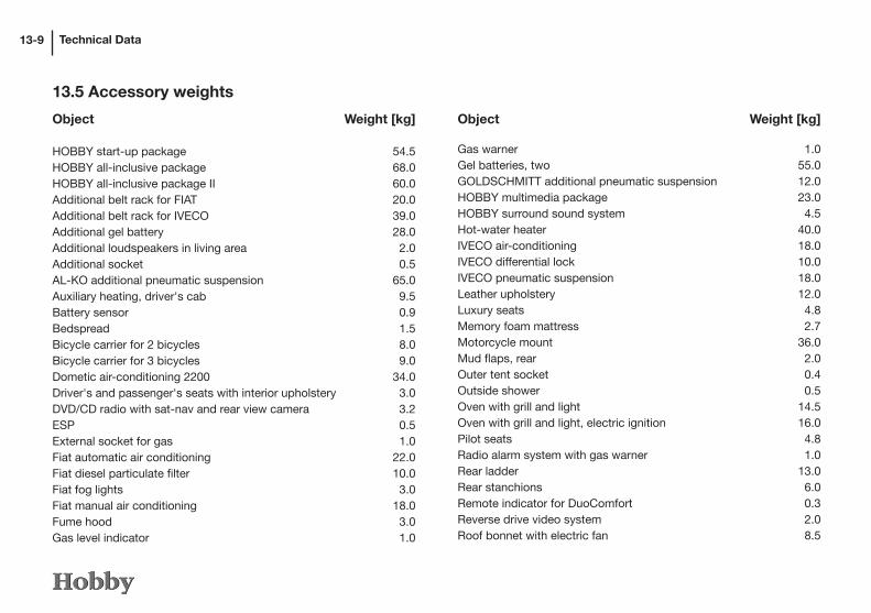
Technical Data
13.5 Accessory weights
13-9
Object Weight [kg] HOBBY start-up package 54.5HOBBY all-inclusive package 68.0HOBBY all-inclusive package II 60.0Additional belt rack for FIAT 20.0Additional belt rack for IVECO 39.0Additional gel battery 28.0Additional loudspeakers in living area 2.0Additional socket 0.5AL-KO additional pneumatic suspension 65.0Auxiliary heating, driver's cab 9.5Battery sensor 0.9Bedspread 1.5Bicycle carrier for 2 bicycles 8.0Bicycle carrier for 3 bicycles 9.0Dometic air-conditioning 2200 34.0Driver's and passenger's seats with interior upholstery 3.0DVD/CD radio with sat-nav and rear view camera 3.2ESP 0.5External socket for gas 1.0Fiat automatic air conditioning 22.0Fiat diesel particulate filter 10.0Fiat fog lights 3.0Fiat manual air conditioning 18.0Fume hood 3.0Gas level indicator 1.0
Gas warner 1.0Gel batteries, two 55.0GOLDSCHMITT additional pneumatic suspension 12.0HOBBY multimedia package 23.0HOBBY surround sound system 4.5Hot-water heater 40.0IVECO air-conditioning 18.0IVECO differential lock 10.0IVECO pneumatic suspension 18.0Leather upholstery 12.0Luxury seats 4.8Memory foam mattress 2.7Motorcycle mount 36.0Mud flaps, rear 2.0Outer tent socket 0.4Outside shower 0.5Oven with grill and light 14.5Oven with grill and light, electric ignition 16.0Pilot seats 4.8Radio alarm system with gas warner 1.0Rear ladder 13.0Rear stanchions 6.0Remote indicator for DuoComfort 0.3Reverse drive video system 2.0Roof bonnet with electric fan 8.5
Object Weight [kg]

Technical Data 13-10
Roof bonnet, Midi-Heki 4.5Roof bonnet, Midi-Heki, electric 5.5SAT antenna 65 cm 16.0SAT antenna 85 cm 18.0SAT receiver 2.0Special metallic silver paintwork 3.0Telescopic arm for flat screen TV 3.0Telescopic arm for flat screen TV, 3-way universal hinged bracket 2.0Telescopic ladder 2.8Tow coupling, removable 32.0Tow coupling, rigid 33.0Tow coupling, rigid, for Sphinx 39.0Tow coupling, rigid, for Toskana (Exclusive) 43.0Truma Combi 6 E heating 1.1Two-cylinder gas unit, DuoComfort 3.0Winter cover for refrigerator grid 0.5
Object Weight [kg]

IndexIx-1
IndexAAccessories upkeep 11-5Additional belt rack 06-31Additional loads 03-3Additional pneumatic spring 03-6Airing 11-1Alcove bed 06-14Automatic transmission 03-8Auxiliary heating in the driver's cab
10-17Awning 05-15
BBar 06-5Basic equipment 03-1Battery circuit breaker 07-14Bed conversion 06-12Berths 06-15Bicycle carrier 05-13Brakes 02-6/04-8Breakdown of devices 07-12Built-in devices 10-1
CCar jack 04-7Carrier 05-14Changeover valve 09-9Changing the tire 04-7Charger place of installation 07-8Charging process 07-9 deep discharge protection 07-9 protecting devices 07-9 when engine is running 07-10Chassis 03-1
Checking the gas system 09-1Children's bed 06-15Chocks 02-8Choosing a parking space 02-10Combined sunshade 06-24 combining the shades 06-24 to shift 06-24Condensation 11-1Control panel 07-3Converting the L-shaped seating arran-
gement 06-31Converting the transverse seat 06-13Cushion arrangements 06-19
DDarkening system 06-25Day and night positions overview 06-37Deep discharge protection 07-9Distribution module 07-6Doors opening and closing 05-7Doors and flaps interior 06-1Driving 02-7 in curves 02-7 in reverse 02-6 sparing the tires 04-1Driving economically 02-7
EElectric heating 10-7Electric power supply 07-7Electrical devices, installation safety tips 07-1Electrical supply unit 07-8Electrical system fuse protection 07-12Emergency equipment 02-9 first-aid kit 02-9
high-visibility vest 02-9 warning triangle 02-9Entrance door 05-7Entrance step 03-5Environment 12-1 disposal 12-3 excrements 12-2 picnic spots 12-3 rubbish 12-3 waste water 12-2Environmental protection 12-1Exhaust fumes 09-2External cleaning 11-2 high-pressure cleaner 11-2 polishing 11-2 waxing 11-2External gas connection 05-11External socket 07-8
FFire protection 02-1First aid kit 02-9Fittings 03-8Flaps opening and closing 05-10Flush toilet 08-5Fold-away bed 06-15Forced ventilation 05-6Freezer compartment 10-20Fresh water pump to drain 11-7Fresh water tank 08-1 dispensing water 08-1 filling up the water 08-1 to empty 08-2Front stowage cabinets 06-2FrostControl 10-3Fuel filler flap 05-1Fume hood 10-25Furniture doors 06-2
Furniture surfaces upkeep 11-5Fuse protection of electrical system 12V circuits 07-12
GGas 09-1Gas bottle container 09-3Gas bottle to change 09-8Gas cooker 10-22 initial operation 10-22 operating the cooker 10-23Gas supply 09-3Gas system 09-1 exhaust fumes 09-2 fixtures and changes 09-1 inspection 09-1 place of installation 09-5 regulator knobs and valves 09-2 shutoff valves and valves 09-5General inspection 02-2
HHanging table 06-11Heating 10-2 control panel 10-2 electric heating 10-7 hot-air heating 10-2 hot-water heating 10-8 to operate 10-2 to switch off 10-6Hinged windows 06-24Hot water supply 08-5Hot-air heating 10-2Hot-water boiler 08-5 to empty 10-6 to fill 10-6 operation in summer 10-4 operation in winter 10-4

Index Ix-2
Hot-water heating system 10-8
IInsect screen 06-23Intelligent battery sensor (IBS) 07-5
KKeys to the vehicle 05-7
LLevelling supports 03-4Loading 02-5/03-1Lowering tables 06-7
MMains connection 07-7Maintenance intervals 11-1Maintenance brake system 04-8Mobile navigation 07-13Modular battery 07-16 changing the battery 07-11 features 07-11 place of installation 07-16Motorcycle carrier 03-8
NNavigation 07-13
OOperating the cooker 10-18Outside shower 08-8 water supply 08-8Oven 10-20Overflow valve fresh water tank 08-2
PPetrol cap 05-12Pillared table 06-9Power saving 02-11
Preparing the vehicle 02-3Profile depth 04-2Push lock 06-4PVC flooring 11-5
RRear external storage locker 02-6Rear view camera 07-14Redirecting electrical devices 02-10Refrigerator 10-18 12V operation 10-18 air supply 05-5 door lock 10-19 to operate 10-18 types of operation 10-18Refuelling 02-7Registration 02-2Regulator knobs 09-2Remote indicator for changeover valve 09-10Resin stains 11-3Rims 04-3Roof air conditioning 10-26Roof bonnets 06-26Roof load 02-6Roof rail 05-12
SSafety belts in the superstructure 06-32Seats in the superstructure 06-30 overview 06-33Securing the vehicle 02-10Service flaps 05-1Shunting 02-6Sliding doors 06-5Spare tire 04-3Sunshade 06-23
TTable edge, to fold down 06-10Table extension 06-8Tables 06-7Taking back end-of-life vehicles 12-4Tar stains 11-3Technical data 13-1Technically permissible maximum weight 03-1Tire pressure 04-2Tire pressure values 13-2Tire repair kit 04-4Tires 04-1Toilet flap 05-11Toilet emptying the cassette 08-7 to use 08-5 upkeep 11-5Tow-bar 03-7TV mount 06-6
UUpkeep 11-2 accessories 11-6 chair and cushion covers, curtains 11-4 fitted carpet 11-5 furniture surfaces 11-4 skylight, windows and doors 11-3 toilet 11-5
VValve for waste water tank 08-4Valves 09-2Vehicle identification numberVehicle tool kit 02-8Ventilation grids 05-6VIN 03-6
WWarning triangle 02-9Wash room 10-17Washroom with sliding elements 06-18Waste water tank 08-3 to empty 08-4Water filler necks 05-11Water filter 08-3Water system 02-10Weights for accessories 13-9Widening the beds 06-13 hanging table 06-11 pillared table model 06-9Windows 06-24Winter operation airing 11-9 anti-freeze measures 11-9 preparations 11-9 waste water tank 11-8Winterising 11-7 containers 11-7 external structure and the base vehicle 11-6 interior fittings 11-8
AppendixA-1
Calculating masses for HOBBY motor homes
The following table enables you to calculate the mass of your own motor home on the basis of the mass data given in this manual.
This calculation must always result in a positive remaining load in order to fulfil current legal requirements.
To determine your remaining load, simply subtract the "mass when the vehicle is ready to start", the "conventional load", all "additional
equipment" as well as your "personal luggage" from the "technically permissible overall mass". Simply enter the date for your personal
motor home in the table on the next page. If you have any questions or if anything is unclear, your HOBBY dealer will be pleased to
assist you.
Your
HOBBY Motor Home Plant
Ing. Harald Striewski GmbH

Appendix A-2
Technically permissible overall mass:
Mass when the vehicle is ready to start (incl. gas, water, electricity, driver and fuel): -
Conventional load (no. of seats [excl. driver] x 75 kg: -
Additional equipment:
1.) -
2.) -
3.) -
4.) -
5.) -
6.) -
7.) -
8.) -
9.) -
10.) -
11.) -
12.) -
13.) -
14.) -
15.) -
Personal luggage = (10 x N) + (10 x L): -
N - Total number of seats (incl. driver)
L - Length of vehicle in meters
Remaining load:
Model:
Under no circumstances may the technically permissible overall mass of the motor home be exceeded!