manual - helmholz – compatible with you part of this manual may be reproduced, processed,...
TRANSCRIPT

Helmholz GmbH & Co. KG | Hannberger Weg 2 | D-91091 Großenseebach | Germany Phone +49 9135 7380-0 | Fax +49 9135 7380-110 | [email protected] | www.helmholz.com
TB20 – Digital, Analog, and System Modules
Manual Version 13 / 1/23/18
Manual order no.: 960-200-0AA01/en


TB20 Modules | Version 13 | 1/23/18 3
Notes
All rights reserved, including those related to the translation, reprinting, and reproduction of this manual or of parts thereof.
No part of this manual may be reproduced, processed, duplicated, or distributed in any form (photocopy, microfilm, or any other methods), even for training purposes or with the use of electronic systems, without written approval from Helmholz GmbH & Co. KG.
All rights reserved in the event of the granting of a patent or the registration of a utility model.
To download the latest version of this manual, please visit our website at www.helmholz.de.
We welcome all ideas and suggestions.
Copyright © 2018 by Helmholz GmbH & Co. KG Hannberger Weg 2, 91091 Großenseebach, Germany
Revision Record
Version
Date Change
1 10/2/2012 First version
2 10/24/2012 LEDs supplemented; corrections in the specifications; fusing section supplemented;
3 11/16/2012 AO U and AO I parameter sets corrected; electronic nameplate; module ID and module type supplemented
4 2/18/2013 2x / 4x DO 2A added; corrections to the analog values tables
5 7/2/2013 Parameter numbers inserted (section 8)
6 10/22/2013 Relay modules 2x/4x changeover; Di AC 230V; AI U 24V inserted
7 4/24/2014 Corrections UL; AI U/I Iso. & AI TC Iso. inserted
8 8/4/2014 AI and AO: Update times supplemented AI Iso. Modules: Channel LEDs documented
9 6/24/2015
Diagnostic IDs supplemented; DO High Feature modules supplemented Potential distributor 4 x 24 V high feature supplemented Spelling of potential distributor corrected Introduction chapter updated AI TC EA data explained (#5618)
10 10/24/2016 AI R/RTD PT100/PT1000 climate supplemented AI U 100V Iso. supplemented AI U 100V load resistance corrected
11 11/16/2017
DI 8/16 GND reading DO 8/16 sink AI/AO U/I: INT16 format of values UL508 additions
12 12/21/2017 8x / 16x DO, sink current corrected; “Hot-Plug” “Hot-Swap”
13 1/8/2018 correction of “DO, sink” connection plan text correction for coding plug potential distributor HF: documentation of input area

TB20 Modules | Version 13 | 1/23/18 4
Table of contents
1. General ..................................................................................................... 10 1.1. Target audience for this manual .............................................................................. 10
1.2. Safety instructions .................................................................................................... 10
1.3. Note symbols and signal words in the manual ....................................................... 11
1.4. Intended use ............................................................................................................. 12
1.5. Improper use ............................................................................................................. 12
1.6. Installation ................................................................................................................ 13
1.6.1. Access restriction .............................................................................................................. 13
1.6.2. Electrical installation ........................................................................................................ 13
1.6.3. Protection against electrostatic discharges ....................................................................... 13
1.6.4. Overcurrent protection ..................................................................................................... 13
1.6.5. EMC protection ................................................................................................................ 13
1.6.6. Operation .......................................................................................................................... 14
1.6.7. Liability ............................................................................................................................. 14
1.6.8. Disclaimer of liability ....................................................................................................... 14
1.6.9. Warranty ........................................................................................................................... 14
2. System overview ....................................................................................... 15 2.1. General ...................................................................................................................... 15
2.2. The components that make up the TB20 I/O system ............................................. 15
2.2.1. Bus coupler ....................................................................................................................... 15
2.2.2. Peripheral modules ........................................................................................................... 15
2.2.3. Power and isolation module ............................................................................................. 16
2.2.4. Power module ................................................................................................................... 17
2.2.5. Final cover ........................................................................................................................ 18
2.2.6. Components in a module ................................................................................................. 18
2.2.7. Module Coding ................................................................................................................. 19
3. Installation and removal ........................................................................... 20 3.1. Installation position ................................................................................................. 20
3.2. Minimum clearance ................................................................................................. 20
3.3. Installing and removing peripheral modules .......................................................... 21
3.3.1. Installation ........................................................................................................................ 21
3.3.2. Removal ............................................................................................................................ 22
3.4. Replacing an electronic module ............................................................................... 25
3.5. Installing and removing the coupler ....................................................................... 29
3.5.1. Installation ........................................................................................................................ 29
3.5.2. Removal ............................................................................................................................ 30
3.6. Installing and removing the final cover .................................................................. 32

TB20 Modules | Version 13 | 1/23/18 5
3.6.1. Installation ........................................................................................................................ 32
3.6.2. Removal ............................................................................................................................ 32
4. Setup and wiring ...................................................................................... 33 4.1. EMC/safety/shielding ............................................................................................... 33
4.2. Front connectors ...................................................................................................... 34
4.3. Wiring the coupler ................................................................................................... 35
4.4. Using power and isolation modules ........................................................................ 36
4.5. Separate power supply segments for the coupler and the I/O components........... 37
4.6. Using power modules ............................................................................................... 38
4.7. Function of the LEDs ................................................................................................ 39
4.8. Electronic nameplate ................................................................................................ 39
4.9. Fusing ........................................................................................................................ 39
4.10. General technical specifications .............................................................................. 40
5. Digital modules ........................................................................................ 41 5.1. Digital Input Modules .............................................................................................. 41
5.1.1. 600-210-0AB01, DI 2 x DC 24 V ....................................................................................... 41
5.1.2. 600-210-0AD01, DI 4 x DC 24 V ...................................................................................... 42
5.1.3. 600-210-0AH01, DI 8 x DC 24 V ...................................................................................... 43
5.1.4. 600-210-0AP21, DI 16 x DC 24 V ..................................................................................... 44
5.1.5. 600-210-0DH01, DI 8 x 24 V GND reading ...................................................................... 45
5.1.6. 600-210-0DP21, DI 16 x 24 V GND reading .................................................................... 46
5.1.7. 600-210-0CC01, DI 3 x DC 24 V, 3-wire .......................................................................... 47
5.1.8. 600-210-0CF21, DI 6 x DC 24 V, 3-wire ........................................................................... 48
5.1.9. 600-211-0BB01, DI 2 x AC 230 V, per channel N ............................................................ 49
5.1.10. 600-211-0BD01, DI 4 x AC 230 V, per channel N ............................................................ 50
5.1.11. 600-211-0BH21, DI 8 x AC 230 V, per channel N ............................................................ 51
5.2. Digital output modules ............................................................................................ 52
5.2.1. 600-220-0AB01, DO 2 x DC 24 V, 500 mA ...................................................................... 52
5.2.2. 600-220-0AD01, DO 4 x DC 24 V, 500 mA ...................................................................... 53
5.2.3. 600-220-0AH01, DO 8 x DC 24 V, 500 mA ...................................................................... 54
5.2.4. 600-220-0AP21, DO 16 x DC 24 V, 500 mA ..................................................................... 55
5.2.5. 600-220-0DH01, DO 8 x DC 24 V, 300 mA, sink ............................................................. 56
5.2.6. 600-220-0DP21, DO 16 x DC 24 V, 300 mA, sink ............................................................ 57
5.2.7. 600-220-7AD01, DO 4 x DC 24 V, 700 mA, High Feature ............................................... 58
5.2.8. 600-220-7AH01, DO 8 x DC 24 V, 700 mA, High Feature ............................................... 60
5.2.9. 600-220-7AP21, DO 16 x DC 24 V, 700 mA, High Feature .............................................. 62
5.2.10. 600-220-0BB01, DO 2 x DC 24 V, 2 A .............................................................................. 64
5.2.11. 600-220-0BD01, DO 4 x DC 24 V, 2 A ............................................................................. 65
5.2.12. 600-222-0AB01, DO 2 x relay, AC 230 V, 5 A, changeover .............................................. 66

TB20 Modules | Version 13 | 1/23/18 6
5.2.13. 600-222-0AD21, DO 4 x relay, AC 230 V, 5 A, changeover ............................................. 67
5.3. Digital Input/Output Modules ................................................................................. 69
5.3.1. 600-230-0AD01, DIO 2 x In / 2 x Out DC 24 V, 500 mA ................................................. 69
5.3.2. 600-230-0AH01, DIO 4 x In / 4 x Out DC 24 V, 500 mA ................................................. 71
5.3.3. 600-230-0AP21, DIO 8 x Out / 8 x In DC 24 V, 500 mA ................................................. 73
6. Analog modules ....................................................................................... 75 6.1. Analog Input Modules .............................................................................................. 75
6.1.1. 600-250-4AB01, AI 2 x I, 0/4-20 mA, ±20 mA, 12-bit ...................................................... 75
6.1.2. 600-250-4AD01, AI 4 x I, 0/4-20 mA, ±20 mA, 12-bit ...................................................... 77
6.1.3. 600-250-7BB01, AI 2 x I, 0/4-20 mA, ±20 mA, Iso., 16-bit ............................................... 79
6.1.4. 600-250-7BD01, AI 4 x I, 0/4-20 mA, ±20 mA, Iso., 16-bit .............................................. 81
6.1.5. 600-250-7BH21, AI 8 x I, 0/4-20 mA, ±20 mA, Iso., 16-bit .............................................. 83
6.1.6. 600-252-4AB01, AI 2 x U, ±10 V, 0–10 V, 1–5 V, 12-bit ................................................... 85
6.1.7. 600-252-4AD01, AI 4 x U, ±10 V, 0–10 V, 1–5 V, 12-bit .................................................. 87
6.1.8. 600-252-7BB01, AI 2 x U, ±10 V, 0–10 V, 1–5 V, Iso., 16-bit ........................................... 89
6.1.9. 600-252-7BD01, AI 4 x U, ±10 V, 0-10 V, 1-5 V, Iso., 16-bit ............................................ 91
6.1.10. 600-252-7BH21, AI 8 x U, ±10 V, 0–10 V, 1–5 V, Iso., 16-bit ........................................... 93
6.1.11. 600-252-4CB01, AI 2 x U, ±24 V, 0–24 V, 12-bit .............................................................. 95
6.1.12. 600-252-4CD01, AI 4 x U, ±24 V, 0–24 V, 12-bit ............................................................. 97
6.1.13. 600-252-7DD01, AI 4 x U, ±100 V, 0-100 V, Iso., 16 bit .................................................. 99
6.1.14. 600-252-7DH21, AI 8 x U, ±100 V, 0-100 V, Iso., 16 bit ................................................ 101
6.1.15. 600-253-4AB01, AI 1/2 x R, RTD, 16-bit, 2/3/4-wire ...................................................... 103
6.1.16. 600-253-4AD01, AI 2/4 x R, RTD, 16-bit, 2/3/4-wire ..................................................... 105
6.1.17. 600-254-4AB01, AI 2 x TC, 16-bit ................................................................................... 107
6.1.18. 600-254-4AD01, AI 4 x TC, 16-bit .................................................................................. 110
6.1.19. 600-254-4AB02, AI 2 x TC, Iso., 16-bit ........................................................................... 113
6.1.20. 600-254-4AD02, AI 4 x TC, Iso., 16-bit .......................................................................... 116
6.1.21. 600-254-4AH22, AI 8 x TC, Iso., 16-bit .......................................................................... 119
6.2. Analog Output Modules ......................................................................................... 122
6.2.1. 600-260-4AB01, AO 2 x I, 0/4–20 mA, 12-bit ................................................................. 122
6.2.2. 600-260-4AD01, AO 4 x I, 0/4-20 mA, 12-bit ................................................................. 124
6.2.3. 600-261-4AB01, AO 2 x U, ±10 V, 0–10 V, 1–5 V, 12-bit ............................................... 126
6.2.4. 600-261-4AD01, AO 4 x U,.±10 V, 0–10 V, 1–5 V, 12-bit............................................... 128
6.3. Basic Analog Value Representation Principles ....................................................... 130
6.3.1. General Information ....................................................................................................... 130
6.3.2. Analog Value Representation with 16-bit Resolution .................................................... 130
6.3.3. Reading Resolution ......................................................................................................... 130
6.4. Analog Value Representation in SIMATIC S7 Format ........................................... 131
6.4.1. Simatic S7 Analog Value Representation for Voltage Measuring Ranges ....................... 131
6.4.2. Simatic S7 Analog Value Representation for Current Measuring Ranges ...................... 133

TB20 Modules | Version 13 | 1/23/18 7
6.4.3. Simatic S7 Analog Value Representation for Resistance Measuring Range .................... 134
6.4.4. Analog value representation for PT100/PT1000 Standard ............................................. 135
6.4.5. Analog value representation for Ni100/Ni1000/LGNi1000 Standard ............................ 135
6.4.6. Analog value representation for PT100/PT1000 climate ................................................ 136
6.4.7. Analog Value Representation for TC .............................................................................. 136
6.5. Analog Value Representation in SIMATIC S5 Format ........................................... 137
6.5.1. Simatic S5 Analog Value Representation for Voltage Measuring Ranges ....................... 137
6.5.2. Simatic S5 Analog Value Representation for Current Measuring Ranges ...................... 138
6.5.3. Simatic S5 Analog Value Representation for Resistance Measuring Range .................... 139
6.6. Analog Value Representation in INT16 Format .................................................... 140
6.6.1. INT16 Analog Value Representation for Voltage Measuring Ranges ............................. 140
6.6.2. INT16 Analog Value Representation for Current Measuring Ranges ............................. 141
6.7. Definition of Operational Error Limit and Basic Error Limit ................................ 142
6.7.1. Operational error limit ................................................................................................... 142
6.7.2. Basic error limit............................................................................................................... 142
6.7.3. Example Showing How to Calculate the Input Error for an Analog Input Module ...... 142
6.8. Connecting Sensors to Analog Inputs ................................................................... 143
6.8.1. Abbreviations Used ......................................................................................................... 143
6.8.2. Signal Cables ................................................................................................................... 143
6.8.3. Connecting Voltage Transmitters .................................................................................. 144
6.8.4. Connecting Current Transmitters .................................................................................. 145
6.8.5. Connecting Resistance Thermometers and Resistors ..................................................... 146
6.8.6. Connecting Thermocouples ........................................................................................... 147
6.9. Connecting Loads and Actuators to Analog Outputs ........................................... 148
6.9.1. Abbreviations Used ......................................................................................................... 148
6.9.2. Connecting Loads/Actuators to Voltage Outputs .......................................................... 148
6.9.3. Connecting Loads/Actuators to Current Outputs .......................................................... 149
7. System Components ............................................................................... 150 7.1. Power and isolation modules ................................................................................. 150
7.1.1. 600-710-0AA01, 24 VDC, 8 A Power and Isolation Module .......................................... 150
7.2. Potential Distributors ............................................................................................. 151
7.2.1. 600-730-4AD01, potential distributor 4 x DC 24 V, High Feature ................................. 151
7.2.2. 600-720-0AH01, potential distributor 9 x DC 24 V ....................................................... 152
7.2.3. 600-720-0BH01, 9 x GND Potential Distributor............................................................. 153
7.2.4. 600-720-0CH01, 10 x AUX Potential Distributor ........................................................... 154
7.2.5. 600-720-0DH01, potential distributor 4 x DC 24 V + 4 x GND ..................................... 155
7.2.6. 600-720-0XH01, 9 x Free Pot. distributor....................................................................... 156
7.3. Power supply .......................................................................................................... 157
7.3.1. 600-700-0AA01, 24 VDC Power Module ........................................................................ 157

TB20 Modules | Version 13 | 1/23/18 8
8. Configuring the Modules’ Parameters.................................................... 159 8.1. General Information .............................................................................................. 159
8.2. Digital Output Modules ......................................................................................... 159
8.2.1. 600-220-7AD01, DO 4 x DC 24 V, 700 mA, High Feature ............................................. 159
8.2.2. 600-220-7AH01, DO 8 x DC 24 V, 700 mA, High Feature ............................................. 160
8.2.3. 600-220-7AP21, DO 16 x DC 24 V, 700 mA, High Feature ............................................ 160
8.2.4. Work method of pulse extension for DO high feature modules ................................... 161
8.3. Analog Input Modules ............................................................................................ 162
8.3.1. 600-250-4AB01, AI 2x I, 0/4–20 mA, +-20 mA, 12-bit .................................................... 162
8.3.2. 600-250-4AD01, AI 4 x I, 0/4–20 mA, ±-20 mA, 12-bit .................................................. 163
8.3.3. 600-250-7BB01, AI 2x I, 0/4–20 mA, +-20 mA, Iso., 16-bit ............................................ 164
8.3.4. 600-250-7BD01, AI 4x I, 0/4–20 mA, +-20 mA, Iso., 16-bit ............................................ 165
8.3.5. 600-250-7BH21, AI 8x I, 0/4-20 mA, +-20 mA, Iso., 16-bit ............................................ 166
8.3.6. 600-252-4AB01, AI 2 x U, ±10 V, 0–10 V, 1–5 V, 12-bit ................................................. 168
8.3.7. 600-252-4AD01, AI 4 x U, ±10 V, 0–10 V, 1–5 V, 12-bit ................................................ 169
8.3.8. 600-252-7BB01, AI 2x U, +-10 V, 0–10 V, 1–5 V, Iso., 16-bit ......................................... 170
8.3.9. 600-252-7BD01, AI 4x U, +-10 V, 0–10 V, 1–5 V, Iso., 16-bit......................................... 171
8.3.10. 600-252-7BH21, AI 8x U, +-10 V, 0–10 V, 1–5 V, Iso., 16-bit ........................................ 172
8.3.11. 600-252-4CB01, AI 2x U, +-24 V, 0–24 V, 12-bit ............................................................ 174
8.3.13. 600-252-4CD01, AI 4x U, +-24 V, 0–24 V, 12-bit ........................................................... 175
8.3.14. 600-252-7DD01, AI 4x U, +-100 V, 0-100 V, Iso., 16-bit ................................................ 176
8.3.15. 600-252-7DH21, AI 8x U, +-100 V, 0-100 V, Iso., 16-bit ................................................ 177
8.3.16. 600-253-4AB01, AI 1/2 x R, RTD, 16-bit, 2/3/4-wire ...................................................... 179
8.3.17. 600-253-4AD01, AI 2/4x R, RTD, 16-bit, 2/3/4-wire ...................................................... 180
8.3.18. 600-254-4AB01, AI 2 x TC, 16-bit ................................................................................... 182
8.3.19. 600-254-4AB02, AI 2 x TC, Iso., 16-bit ........................................................................... 182
8.3.20. 600-254-4AD01, AI 4 x TC, 16-bit .................................................................................. 183
8.3.21. 600-254-4AD02, AI 4 x TC, Iso., 16-bit .......................................................................... 183
8.3.22. 600-254-4AH22, AI 8 x TC, Iso., 16-bit .......................................................................... 184
8.4. Analog Output Modules ......................................................................................... 186
8.4.1. 600-260-4AB01, AO 2 x I, 0/4–20 mA, 12-bit ................................................................. 186
8.4.2. 600-260-4AD01, AO 4 x I, 0/4–20 mA, 12-bit ................................................................ 187
8.4.3. 600-261-4AB01, AO 2x U, +-10 V, 0–10 V, 1–5 V, 12-bit ............................................... 188
8.4.4. 600-261-4AD01, AO 4 x U, ±10 V, 0–10 V, 1–5 V, 12-bit............................................... 189
9. Alarms .................................................................................................... 190 9.1. Diagnostic IDs ........................................................................................................ 190
9.2. Process alarms ......................................................................................................... 190
9.2.1. Process alarms of the analog input modules .................................................................. 190
10. Dimensions ............................................................................................ 191

TB20 Modules | Version 13 | 1/23/18 9
11. Spare parts ............................................................................................. 192 11.1. Base modules .......................................................................................................... 192
11.1.1. 14 mm width standard base module .............................................................................. 192
11.1.2. 25 mm width base module ............................................................................................. 192
11.1.3. Power and isolation base module ................................................................................... 192
11.1.4. Power base module ......................................................................................................... 193
11.2. Front connectors .................................................................................................... 193
11.2.1. 10-terminal front connector ........................................................................................... 193
11.2.2. 20-terminal front connector ........................................................................................... 193
11.3. Electronic modules ................................................................................................. 194
11.4. Final cover .............................................................................................................. 194

TB20 Modules | Version 13 | 1/23/18 10
1. General
This operating manual applies only to devices, assemblies, software, and services of Helmholz GmbH & Co. KG.
1.1. Target audience for this manual
This description is only intended for trained personnel qualified in control and automation engineering who are familiar with the applicable national standards. For installation, commissioning, and operation of the components, compliance with the instructions and explanations in this operating manual is essential.
Configuration, execution, and operating errors can interfere with the proper operation of the TB20 devices and result in personal injury as well as material or environmental damage. Only suitably qualified personnel may operate the TB20 devices!
Qualified personnel must ensure that the application and use of the products described meet all the safety requirements, including all relevant laws, regulations, provisions, and standards.
1.2. Safety instructions
The safety instructions must be observed in order to prevent harm to persons and living creatures, material goods, and the environment. The safety instructions indicate possible hazards and provide information on how hazardous situations can be prevented.

TB20 Modules | Version 13 | 1/23/18 11
1.3. Note symbols and signal words in the manual
If the hazard warning is ignored, there is an imminent danger to life and health of people from electrical voltage.
If the hazard warning is ignored, there is a probable danger to life and health of people from electrical voltage.
If the hazard warning is ignored, people can be injured or harmed.
Draws attention to sources of error that can damage equipment or the environment.
Gives an indication for better understanding or preventing errors.

TB20 Modules | Version 13 | 1/23/18 12
1.4. Intended use
The TB20 I/O system is an open, modular, and distributed peripheral system designed to be mounted on a 35 mm DIN rail.
Communication with a higher-level control system takes place via a bus system / network through a TB20 bus coupler. Up to 64 modules from the TB20 range can be set up on a bus coupler. The bus couplers support hot plug for replacing modules during ongoing operation.
All components are supplied with a factory hardware and software configuration. The user must carry out the hardware and software configuration for the conditions of use. Modifications to hardware or software configurations which are beyond the documented options are not permitted and nullify the liability of Helmholz GmbH & Co. KG.
The TB20 devices should not be used as the only means for preventing hazardous situations on machinery and equipment.
Successful and safe operation of the TB20 devices requires proper transport, storage, installation, assembly, installation, commissioning, operation, and maintenance.
The ambient conditions provided in the technical specifications must be adhered to.
The TB20 systems have a protection rating of IP20 and must have a control box/cabinet fitted to protect against environmental influences in an electrical operating room. To prevent unauthorized access, the doors of control boxes/cabinets must be closed and possibly locked during operation.
TB20 devices can be equipped with modules that can carry dangerously high voltages. The voltages connected to the TB20 devices can result in hazards during work on the TB20 devices.
1.5. Improper use
The consequences of improper use may include injury of the user or third parties, as well as property damage to the control system, the product, or environment. Use TB20 devices only as intended!

TB20 Modules | Version 13 | 1/23/18 13
1.6. Installation
1.6.1. Access restriction
The modules are open operating equipment and must only be installed in electrical equipment rooms, cabinets, or housings.
Access to the electrical equipment rooms, cabinets, or housings must only be possible using a tool or key, and access should only be granted to trained or authorized personnel.
1.6.2. Electrical installation
Observe the regional safety regulations.
TB20 devices can be equipped with modules that can carry dangerously high voltages. The voltages connected to the TB20 devices can result in hazards during work on the TB20 devices.
1.6.3. Protection against electrostatic discharges
To prevent damage through electrostatic discharges, the following safety measures are to be followed during assembly and service work:
• Never place components and modules directly on plastic items (such as polystyrene, PE film) or in their vicinity.
• Before starting work, touch the grounded housing to discharge static electricity.
• Only work with discharged tools.
• Do not touch components and assemblies on contacts.
1.6.4. Overcurrent protection
To protect the TB20 and the supply line, a slow-blowing 8 A line protection fuse is required.
1.6.5. EMC protection
To ensure electromagnetic compatibility (EMC) in your control cabinets in electrically harsh environments, the known rules of EMC-compliant configuration are to be observed in the design and construction.

TB20 Modules | Version 13 | 1/23/18 14
1.6.6. Operation
Operate the TB20 only in flawless condition. The permissible operating conditions and performance limits must be adhered to.
Retrofits, changes, or modifications to the device are strictly forbidden.
The TB20 is an operating means intended for use in industrial plants. During operation, the TB20 can carry dangerous voltages. During operation, all covers on the unit and the installation must be closed in order to ensure protection against contact.
1.6.7. Liability
The contents of this manual are subject to technical changes resulting from the continuous development of products of Helmholz GmbH & Co. KG. In the event that this manual contains technical or clerical errors, we reserve the right to make changes at any time without notice. No claims for modification of delivered products can be asserted based on the information, illustrations, and descriptions in this documentation. Beyond the instructions contained in the operating manual, the applicable national and international standards and regulations must also in any case be observed.
1.6.8. Disclaimer of liability
Helmholz GmbH & Co. KG is not liable for damages if these were caused by use or application of products that was improper or not as intended.
Helmholz GmbH & Co. KG assumes no responsibility for any printing errors or other inaccuracies that may appear in the operating manual, unless there are serious errors about which Helmholz GmbH & Co. KG was already demonstrably aware.
Beyond the instructions contained in the operating manual, the applicable national and international standards and regulations must also in any case be observed.
Helmholz GmbH & Co. KG is not liable for damage caused by software that is running on the user’s equipment which compromises, damages, or infects additional equipment or processes through the remote maintenance connection and which triggers or permits unwanted data transfer.
1.6.9. Warranty
Report any defects to the manufacturer immediately after discovery of the defect.
The warranty is not valid in case of:
• Failure to observe these operating instructions
• Use of the device that is not as intended
• Improper work on and with the device
• Operating errors
• Unauthorized modifications to the device
The agreements met upon contract conclusion under “General Terms and Conditions of Helmholz GmbH & Co. KG” apply.
TB20 Modules | Version 13 | 1/23/18 15
2. System overview
2.1. General
The TB20 I/O system is an open, modular, and distributed peripheral system designed to be mounted on a 35mm DIN rail.
It is made up of the following components:
• Bus couplers
• Peripheral modules
• Power and isolation modules
• Power modules
By using these components, you can build a custom automation system that is tailored to your specific needs and that can have up to 64 modules connected in series to a bus coupler. All components have a protection rating of IP20.
2.2. The components that make up the TB20 I/O system
2.2.1. Bus coupler
The system’s bus coupler includes a bus interface and a power module. The bus interface is responsible for establishing a connection to the higher-level bus system and is used to exchange I/O signals with the automation system’s CPU.
The power module is responsible for powering the coupler’s electronics and all connected peripheral modules.
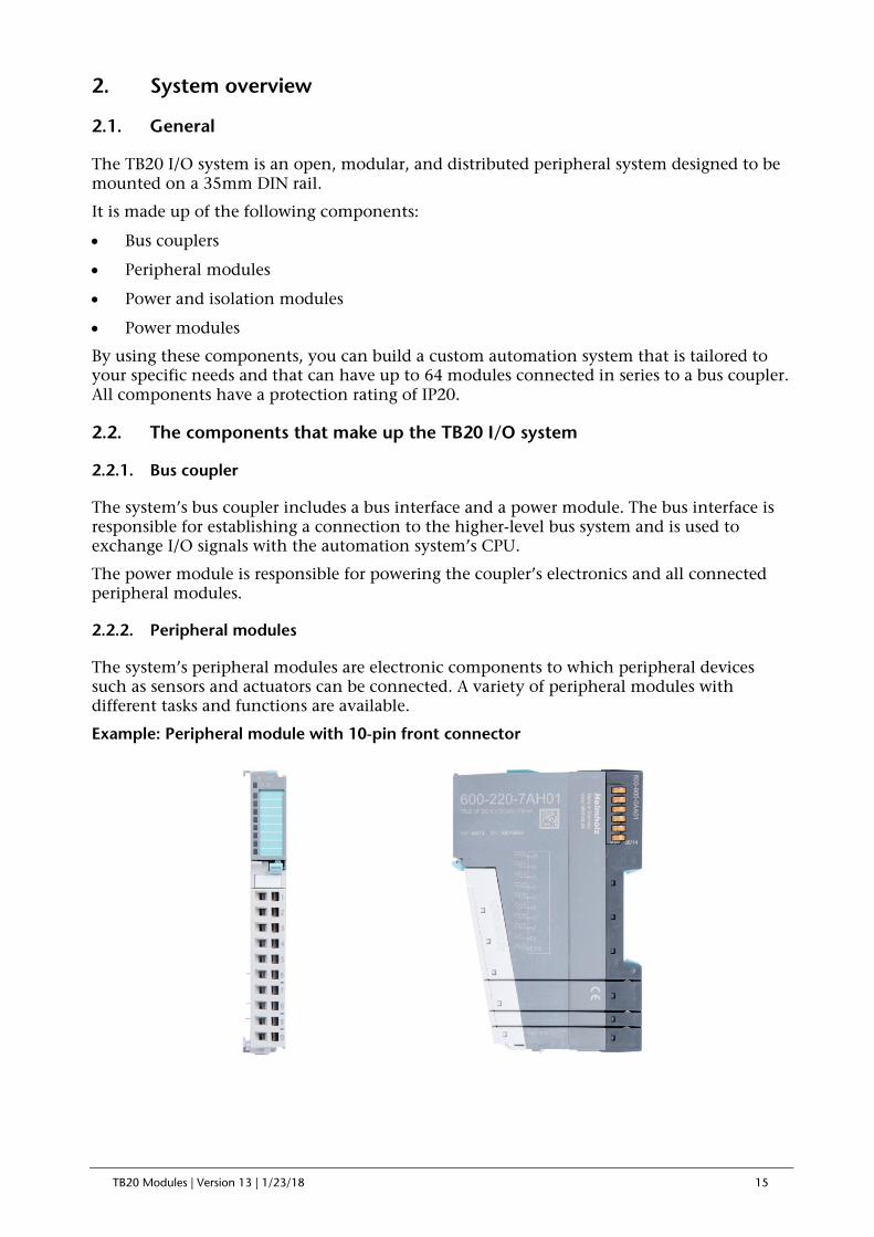
2.2.2. Peripheral modules
The system’s peripheral modules are electronic components to which peripheral devices such as sensors and actuators can be connected. A variety of peripheral modules with different tasks and functions are available.
Example: Peripheral module with 10-pin front connector

TB20 Modules | Version 13 | 1/23/18 16
Example: Peripheral module with 20-pin front connector
2.2.3. Power and isolation module
The system’s bus coupler provides the supply voltage for the communications bus (5 V, top) and for external signals (24 V, bottom). These voltages are passed from module to module through the base modules.
Power and isolation modules make it possible to segment the power supply for external signals into individual power supply sections that are powered separately. On the other hand, the communications bus signals and supply voltage for the communications bus are simply passed through, in contrast to the way they are handled in the power modules (see section 2.2.4).
Power and insulation modules have a lighter body color.

TB20 Modules | Version 13 | 1/23/18 17
2.2.4. Power module
The system’s bus coupler provides the supply voltage for the communications bus (5 V, top) and for external signals (24 V, bottom). These voltages are passed from module to module through the base modules.
Power modules make it possible to segment the power supply for both external signals and the communication bus into individual power supply sections that are powered separately.
Power modules deliver all necessary power to the peripheral modules connected after them and, if applicable, all the way to the next power module or power and isolation module. A power module is required whenever the power supplied by the coupler alone is not sufficient, e.g., when there are a large number of modules with high power requirements. The “TB20 ToolBox” configuration program can be used to determine whether power modules are needed, as well as how many of them will be needed.
Power modules have a lighter body color.
TB20 Modules | Version 13 | 1/23/18 18
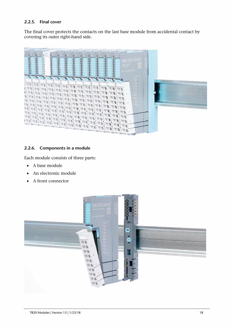
2.2.5. Final cover
The final cover protects the contacts on the last base module from accidental contact by covering its outer right-hand side.
2.2.6. Components in a module
Each module consists of three parts:
• A base module
• An electronic module
• A front connector

TB20 Modules | Version 13 | 1/23/18 19
2.2.7. Module Coding
Electronic modules and base modules feature coding elements meant to prevent the wrong spare electronic modules from being plugged in during maintenance and repairs.
These coding elements consist of a coding plug on the electronic module and a coding socket on the base module (see following figure).
The coding plug and coding socket can each be in one of eight different positions. Each of these eight positions can be used for a specific type of module (Digital In, Digital Out, Analog In, Analog Out, Power). It will only be possible to plug an electronic module into a base module if the position of the coding plug and the position of the coding socket match. If the positions differ, the electronic module is mechanically blocked.

TB20 Modules | Version 13 | 1/23/18 20
3. Installation and removal
TB20 modules can carry lethal voltage.
Before starting any work on TB20 system components, make sure to de-energize all components and the cables supplying them with power! Carrying out work when the system is live poses the risk of fatal electrocution!
Installation must be carried out according to VDE 0100/IEC 364 and in accordance with applicable national standards. The TB20 IO system has protection rating IP20. If a higher protection rating is required, the system must be installed in a housing or control cabinet. In order to ensure safe operation, the ambient temperature must not exceed 60 °C.
3.1. Installation position
The TB20 I/O system can be installed in any position.
Optimal ventilation and thus the maximum ambient temperature can only be achieved in the horizontal installation layout.
3.2. Minimum clearance
It is recommended to adhere to the minimum clearances specified when installing the coupler and modules. Adhering to these minimum clearances will ensure that:
• the modules can be installed and removed without having to remove any other system components
• there will be enough space to make connections to all existing terminals and contacts using commercially available accessories.
• there will be enough space for potentially necessary cable management systems.
The minimum clearances for mounting TB20 components are: 30 mm on the top and on bottom and 10 mm on each side.

TB20 Modules | Version 13 | 1/23/18 21
3.3. Installing and removing peripheral modules
3.3.1. Installation
Installing an assembled peripheral module
Place the assembled module on the DIN rail by moving it straight towards the rail. Make sure that the module engages the upper and lower guide elements of the previous module. Then push the upper part of the module towards the DIN rail until the rail fastener fastens into place on the inside snaps with a soft click.
Installing the individual parts of a peripheral module one after the other:
Place the base module on the DIN rail from below in an inclined position. Then push the upper part of the base module towards the rail until the module is parallel to the rail and the rail fastener on the inside snaps into place with a soft click.
Place an electronic module with matching coding (see “Module Coding” in section 2.2.7) on the base module in a straight line from above and then gently push it onto the base module until both modules are fully resting on top of one another and the module fastener snaps into place with a soft click.
Finally, place the front connector on the electronic module from below in an inclined position and then gently push it onto the electronic module until the front connector fastener snaps into place with a soft click.

TB20 Modules | Version 13 | 1/23/18 22
3.3.2. Removal
To remove a peripheral module, follow the four steps below:
Step 1: Remove the front connector
To remove the front connector, push the tab above the front connector upwards (see the picture below). This will push out the front connector, after which you can pull it out.

TB20 Modules | Version 13 | 1/23/18 23
Step 2: Remove the electronic module
To do so, use your middle finger to push on the lever from above and then use your thumb and index finger to pull out the electronic module while holding the lever down (see the picture below).

TB20 Modules | Version 13 | 1/23/18 24
Step 3: Release the base module
Use a screwdriver to release the base module. Turn the screwdriver 90° counterclockwise to release.
Step 4: Remove the base module
Remove the base module by pulling it towards you.

TB20 Modules | Version 13 | 1/23/18 25
3.4. Replacing an electronic module
The procedure for replacing the electronic module on a peripheral module consists of four steps.
If you need to replace the electronic module while the system is running, make sure to take into account the general technical specifications for the bus coupler being used.
TB20 modules can carry lethal voltage.
Before starting any work on TB20 system components, make sure to de-energize all components and the cables supplying them with power! Carrying out work when the system is live poses the risk of fatal electrocution!
Note the wiring diagram of the system and switch off dangerous voltages before starting work!
Step 1: Remove the front connector
To remove the front connector, push the tab above the front connector upwards (see the picture below). This will push out the front connector, after which you can pull it out.

TB20 Modules | Version 13 | 1/23/18 26
Step 2: Remove the electronic module
To remove the electronic module, use your middle finger to push on the lever from above and then use your thumb and index finger to pull out the electronic module while holding the lever down (see the picture below).

TB20 Modules | Version 13 | 1/23/18 27
Step 3: Plug in a new electronic module
The electronic module must be snapped into place on the base module with a single continuous movement. If the electronic module is not snapped into place firmly and straight on the base module, bus malfunctions may occur.

TB20 Modules | Version 13 | 1/23/18 28
If the electronic module cannot be plugged into the base module, check whether the coding elements on the electronic module and base module (see figure below) match. If the coding elements on the electronic module do not match those on the base module, you may be attempting to plug in the wrong electronic module.
For more information on coding elements, please consult section 2.2.7.
Step 4: Plug in the front connector

TB20 Modules | Version 13 | 1/23/18 29
3.5. Installing and removing the coupler
3.5.1. Installation
Place the coupler, together with the attached base module, on the DIN rail by moving it straight towards the rail. Then push the coupler towards the rail until the base module’s rail fastener snaps into place with a soft click.
Step 2: Secure the coupler on the DIN rail
Use the locking lever on the left side of the coupler to lock the coupler into position on the DIN rail.

TB20 Modules | Version 13 | 1/23/18 30
3.5.2. Removal
Step 1: Release the locking mechanism
Release the locking lever on the left side of the coupler in order to disengage it from the DIN rail.
Step 2: Remove the coupler
Use your middle finger to push on the lever from above and use your thumb and index finger to pull out the coupler while holding the lever down.

TB20 Modules | Version 13 | 1/23/18 31
Step 3: Release the base module
Use a screwdriver to release the base module.
Step 4: Remove the base module
Remove the base module by pulling it towards you.
TB20 Modules | Version 13 | 1/23/18 32
3.6. Installing and removing the final cover
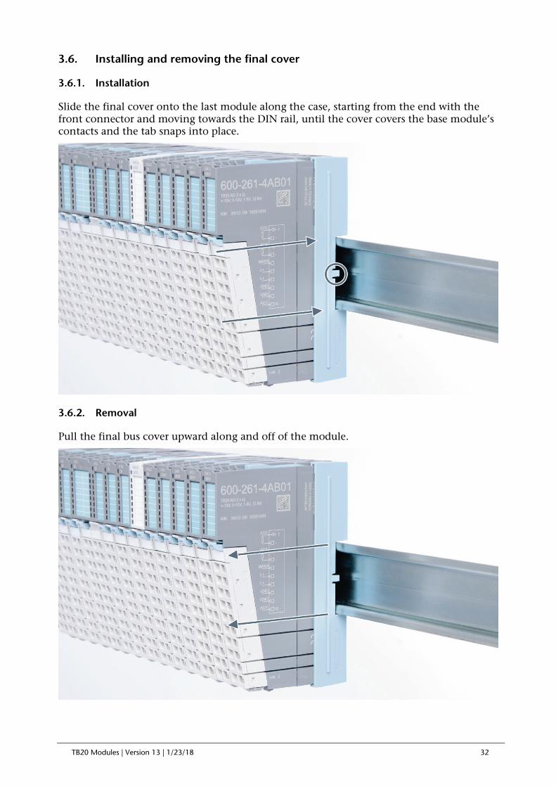
3.6.1. Installation
Slide the final cover onto the last module along the case, starting from the end with the front connector and moving towards the DIN rail, until the cover covers the base module’s contacts and the tab snaps into place.
3.6.2. Removal
Pull the final bus cover upward along and off of the module.

TB20 Modules | Version 13 | 1/23/18 33
4. Setup and wiring
4.1. EMC/safety/shielding
The TB20 IO system complies with EU Directive 2004/108/EC (“Electromagnetic Compatibility”).
One effective way to protect against disturbances caused by electromagnetic interference is to shield electric cables, wires, and components.
When setting up the system and laying the necessary cables, make sure to fully comply with all standards, regulations, and rules regarding shielding (please also consult the relevant guidelines and documents published by the PROFIBUS User Organization). All work must be done professionally!
Shielding faults can result in serious malfunctions, including the system’s failure.
To ensure electromagnetic compatibility (EMC) in your control cabinets in electrically harsh environments, the following EMC rules are to be observed in the design and the setup:
• All metal parts of the cabinet are to be connected with each other over a large area with good conductivity (no paint on paint). Where necessary, use contact washers or serrated washers.
• The cabinet door must be connected to the ground straps (top, middle, bottom) over as short a distance as possible.
• Signal cables and power cables are to be laid separated spatially by a minimum distance of 20 cm from each in order to avoid coupling paths.
• Run signal lines only from one level into the cabinet if possible.
• Unshielded cables in the same circuit (outgoing and incoming conductors) must be twisted if possible.
• Contactors, relays, and solenoid valves in the closet, or in adjacent cabinets if applicable, must be provided with quenching combinations; e.g., with RC elements, varistors, diodes.
• Do not lay wires freely in the closet; instead, run them as closely as possible to the cabinet housing or mounting panels. This also applies to reserve cables. These must be grounded on at least one end, and it is better if they are grounded at both ends (additional shielding effect).
• Unnecessary line lengths should be avoided. Coupling capacitances and inductances are kept low in this way.
• Analog signal lines and data lines must be shielded.

TB20 Modules | Version 13 | 1/23/18 34
4.2. Front connectors
The front connector’s spring-clamp terminals are designed for a cross-sectional cable area of up to 1.5 mm² (16–22 AWG) with or without ferrules.
It is also possible, for example, to connect two 0.75 mm² wires to a single spring-type terminal, provided the maximum cross-sectional cable area of 1.5 mm² per terminal is not exceeded.
The cables can be attached to the underside of the front connector with a cable tie.

TB20 Modules | Version 13 | 1/23/18 35
4.3. Wiring the coupler
A power supply unit is integrated into the bus coupler. The power supply unit is responsible for powering the peripheral modules connected to the coupler.
In turn, it draws its own power from the three-pin connector on the front (24 VDC, GND, AUX).
The 24 V connector is used to power two buses:
• The power bus used to power the I/O components (24 VDC, GND, AUX)
• The communications bus used to power the electronics in the peripheral modules
The AUX pin can be used to connect and use an additional voltage potential. Every peripheral module has an AUX terminal on its front connector (the bottommost terminal, i.e., terminals 10 and 20).
The coupler and the modules are grounded via the shield contact to the DIN rail. The DIN rail must be grounded. The surface of the DIN rail must be clean and conduct electricity well.

TB20 Modules | Version 13 | 1/23/18 36
4.4. Using power and isolation modules
Power and isolation modules make it possible to segment the power supply for external signals (24 V, GND, AUX) into individual power supply sections that are powered separately.
The order no. for the power and isolation module for 24 V signals is 600-710-0AA01.
Its electronic module and base module have the same light gray color as the front connector, ensuring that all power and isolation modules will stand out visually in the system and make it easy to clearly distinguish each individual power supply segment.

TB20 Modules | Version 13 | 1/23/18 37
4.5. Separate power supply segments for the coupler and the I/O components
If the power supply for the coupler needs to be separate from the power supply for the I/O modules, a power and isolation module can be used right after the coupler.

TB20 Modules | Version 13 | 1/23/18 38
4.6. Using power modules
Power modules deliver all necessary power to the connected peripheral modules and, if applicable, all the way to the next power module or power and isolation module. Power modules must be used whenever the power supplied by the coupler alone is not sufficient, that is, when there are a large number of modules on the bus. The “TB20 ToolBox” parameter configuration and diagnosis program can be used to calculate a system’s total current draw.
24 VDC, GND, and AUX are fed into the terminals on the front, while the connected modules are powered through the base modules’ bus system.
The order no. for the power module is 600-700-0AA01. The electronic module of the power module is light gray like the front connector. The base module of the power module is light gray with a dark top part.

TB20 Modules | Version 13 | 1/23/18 39
4.7. Function of the LEDs
The topmost OK/SF LED indicates the current system status of each module.
Solid blue light: The module is running (RUN)
Slowly flashing blue light: The module is stopped (STOP); substitute values (if any) are being applied
Quickly flashing blue light: The module is idle (IDLE); its parameters have not been configured yet
Solid red light: The module is indicating a diagnostic error
Flashing red light: The module is indicating a parameter assignment error
The red “SF” LED lights will only be shown on modules with configurable parameters or diagnostic capabilities.
IDLE mode (quickly flashing blue LED) indicates modules that have not been added to ongoing system operation by the coupler. One of the reasons that can cause this is an incorrect configuration (wrong module model on the slot).
4.8. Electronic nameplate
All of a TB20 module’s important information can be found on its electronic nameplate. This information includes, for example, the corresponding module ID, module type, order number, unique serial number, hardware version, firmware version, and internal range of functionalities.
This information can be read in a number of ways, one of which is using the “TB20 ToolBox” configuration and diagnosis program. The modules’ electronic nameplates not only make it possible to prevent configuration errors (setup), but also make maintenance (servicing) easier.
4.9. Fusing
The TB20 coupler’s and power modules’ power supply must be externally fused with a slow-blowing fuse, maximum 8 A, appropriate for the required maximum current.

TB20 Modules | Version 13 | 1/23/18 40
4.10. General technical specifications
Certifications CE Noise immunity DIN EN 61000-6-2 “EMC Immunity” Interference emission DIN EN 61000-6-4 “EMC Emission”
Vibration and shock resistance DIN EN 60068-2-8:2008 “Vibration” DIN EN 60068-27:2010 “Shock”
Isolation voltage 1.5 kV Protection rating IP 20 Relative humidity 95% without condensation Installation position Any Permissible ambient temperature 0 °C to 60 °C Transport and storage temperature -20 °C to 80 °C Pollution degree 2 (for UL508 certified modules)

TB20 Modules | Version 13 | 1/23/18 41
5. Digital modules
5.1. Digital Input Modules
5.1.1. 600-210-0AB01, DI 2 x DC 24 V
Characteristics
• 2 inputs, electrically isolated from the backplane bus
• 24 V DC input voltage
• Can accommodate 2-wire proximity sensors
• A blue LED indicates the module's operating status
• Green LEDs (one for each input) indicate the inputs’ states
Pin assignment
Technical data
Order no. 600-210-0AB01 Name DI 2 x DC 24 V Module ID / module type 1200 dec. / 0x0102 Number of inputs 2 Electrically isolated from backplane bus Yes Channels electrically isolated from each other No Current draw External Max. 0 mA Internal Max. 22 mA Power dissipation Max. 0.5 W Input characteristic curve Type 2, EN 61131-2 Reverse polarity protection for inputs Yes Input voltage For signal “0” -3 V to 9 V For signal “1” 12 V to 30 V Hot plug-compatible Yes Weight Approx. 70 g Certification UL 508
Connection I/O 1 Input 0 2 Input 1 3 GND 4 GND 5 L+, 24 VDC 6 L+, 24 VDC 7 AUX 8 AUX 9 L+, 24 VDC 10 AUX

TB20 Modules | Version 13 | 1/23/18 42
5.1.2. 600-210-0AD01, DI 4 x DC 24 V
Characteristics
• 4 inputs, electrically isolated from the backplane bus
• 24 V DC input voltage
• Can accommodate 2-wire proximity sensors
• A blue LED indicates the module's operating status
• Green LEDs (one for each input) indicate the inputs’ states
Pin assignment
Technical data
Order no. 600-210-0AD01 Name DI 4 x DC 24 V Module ID / module type 1400 dec. / 0x0104 Number of inputs 4 Electrically isolated from backplane bus Yes Channels electrically isolated from each other No Current draw External Max. 0 mA Internal Max. 22 mA Power dissipation Max. 0.95 W Input characteristic curve Type 2, EN 61131-2 Reverse polarity protection for inputs Yes Input voltage For signal “0” -3 V to 9 V For signal “1” 12 V to 30 V Hot plug-compatible Yes Weight Approx. 70 g Certification UL 508
Connection I/O 1 Input 0 2 Input 1 3 Input 2 4 Input 3 5 L+, 24 VDC 6 L+, 24 VDC 7 AUX 8 AUX 9 L+, 24 VDC 10 AUX

TB20 Modules | Version 13 | 1/23/18 43
5.1.3. 600-210-0AH01, DI 8 x DC 24 V
Characteristics
• 8 inputs, electrically isolated from the backplane bus
• 24 V DC input voltage
• Can accommodate 2-wire proximity sensors
• A blue LED indicates the module's operating status
• Green LEDs (one for each input) indicate the inputs’ states
Pin assignment
Technical data
Order no. 600-210-0AH01 Name DI 8 x DC 24 V Module ID / module type 1800 dec. / 0x0108 Number of inputs 8 Electrically isolated from backplane bus Yes Channels electrically isolated from each other No Current draw External Max. 0 mA Internal Max. 22 mA Power dissipation Max. 1.85 W Input characteristic curve Type 2, EN 61131-2 Reverse polarity protection for inputs Yes Input voltage For signal “0” -3 V to 9 V For signal “1” 12 V to 30 V Hot plug-compatible Yes Weight Approx. 70 g Certification UL 508
Connection I/O 1 Input 0 2 Input 1 3 Input 2 4 Input 3 5 Input 4 6 Input 5 7 Input 6 8 Input 7 9 L+, 24 VDC 10 AUX

TB20 Modules | Version 13 | 1/23/18 44
5.1.4. 600-210-0AP21, DI 16 x DC 24 V
Characteristics
• 16 inputs, electrically isolated from the backplane bus
• 24 V DC input voltage
• Can accommodate 2-wire proximity sensors
• A blue LED indicates the module's operating status
• Green LEDs (one for each input) indicate the inputs’ states
Pin assignment
Technical data
Order no. 600-210-0AP21 Name DI 16 x DC 24 V Module ID / module type 1900 dec. / 0x0109 Number of inputs 16 Electrically isolated from backplane bus Yes Channels electrically isolated from each other No Current draw External Max. 0 mA Internal Max. 23 mA Power dissipation Max. 3.7 W Input characteristic curve Type 2, EN 61131-2 Reverse polarity protection for inputs Yes Input voltage For signal “0” -3 V to 9 V For signal “1” 12 V to 30 V Hot plug-compatible Yes Weight Approx. 110 g Certification UL 508
Connection I/O Connection I/O 1 Input 0 11 Input 8 2 Input 1 12 Input 9 3 Input 2 13 Input 10 4 Input 3 14 Input 11 5 Input 4 15 Input 12 6 Input 5 16 Input 13 7 Input 6 17 Input 14 8 Input 7 18 Input 15 9 L+, 24 VDC 19 L+, 24 VDC 10 AUX 20 AUX

TB20 Modules | Version 13 | 1/23/18 45
5.1.5. 600-210-0DH01, DI 8 x 24 V GND reading
Characteristics
• 8 inputs, electrically isolated from the backplane bus
• A blue LED indicates the module's operating status
• Green LEDs (one for each input) indicate the inputs’ states
Pin assignment
Technical data
Order no. 600-210-0DH01 Name DI 8 x 24 V GND reading Module ID / module type 1801 dec. / 0x0108 Number of inputs 8 Electrically isolated from backplane bus Yes Channels electrically isolated from each other No Current draw External Max. 0 mA Internal Max. 22 mA Power dissipation Max. 1.85 W Input characteristic curve Type 3, EN 61131-2 Reverse polarity protection for inputs Yes Input voltage For signal “0” Vcc -5 .. Vcc For signal “1” 0 V … Vcc-11 V Hot plug-compatible Yes Weight Approx. 70 g Certification UL 508
1
10
L+
GND
DI1
DI2
DI3
DI4
DI5
DI6
DI7
DI0
AUX
Connection I/O 1 Input 0 2 Input 1 3 Input 2 4 Input 3 5 Input 4 6 Input 5 7 Input 6 8 Input 7 9 L+, 24 VDC 10 AUX
TB20 Modules | Version 13 | 1/23/18 46
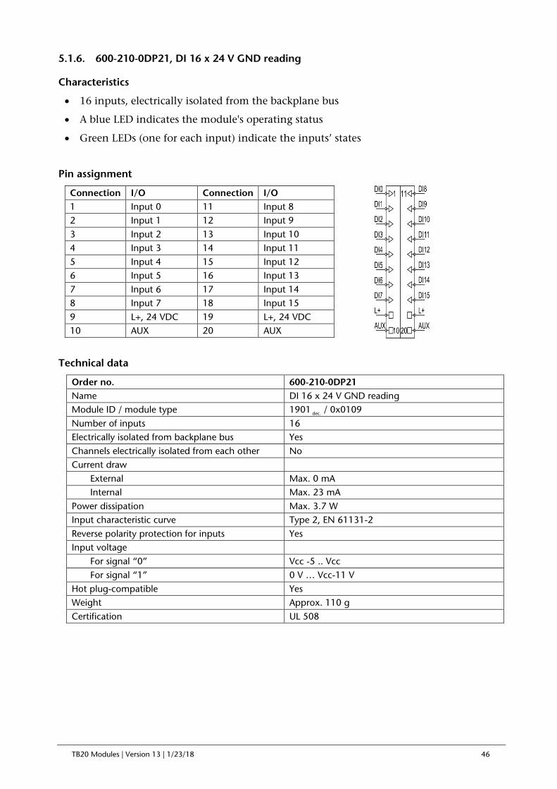
5.1.6. 600-210-0DP21, DI 16 x 24 V GND reading
Characteristics
• 16 inputs, electrically isolated from the backplane bus
• A blue LED indicates the module's operating status
• Green LEDs (one for each input) indicate the inputs’ states
Pin assignment
Technical data
Order no. 600-210-0DP21 Name DI 16 x 24 V GND reading Module ID / module type 1901 dec. / 0x0109 Number of inputs 16 Electrically isolated from backplane bus Yes Channels electrically isolated from each other No Current draw External Max. 0 mA Internal Max. 23 mA Power dissipation Max. 3.7 W Input characteristic curve Type 2, EN 61131-2 Reverse polarity protection for inputs Yes Input voltage For signal “0” Vcc -5 .. Vcc For signal “1” 0 V … Vcc-11 V Hot plug-compatible Yes Weight Approx. 110 g Certification UL 508
Connection I/O Connection I/O 1 Input 0 11 Input 8 2 Input 1 12 Input 9 3 Input 2 13 Input 10 4 Input 3 14 Input 11 5 Input 4 15 Input 12 6 Input 5 16 Input 13 7 Input 6 17 Input 14 8 Input 7 18 Input 15 9 L+, 24 VDC 19 L+, 24 VDC 10 AUX 20 AUX
TB20 Modules | Version 13 | 1/23/18 47
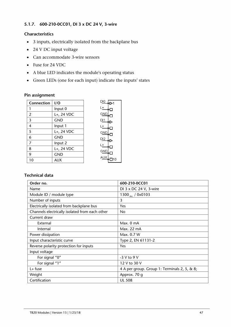
5.1.7. 600-210-0CC01, DI 3 x DC 24 V, 3-wire
Characteristics
• 3 inputs, electrically isolated from the backplane bus
• 24 V DC input voltage
• Can accommodate 3-wire sensors
• Fuse for 24 VDC
• A blue LED indicates the module's operating status
• Green LEDs (one for each input) indicate the inputs’ states
Pin assignment
Technical data
Order no. 600-210-0CC01 Name DI 3 x DC 24 V, 3-wire Module ID / module type 1300 dec. / 0x0103 Number of inputs 3 Electrically isolated from backplane bus Yes Channels electrically isolated from each other No Current draw External Max. 0 mA Internal Max. 22 mA Power dissipation Max. 0.7 W Input characteristic curve Type 2, EN 61131-2 Reverse polarity protection for inputs Yes Input voltage For signal “0” -3 V to 9 V For signal “1” 12 V to 30 V L+ fuse 4 A per group. Group 1: Terminals 2, 5, & 8; Weight Approx. 70 g Certification UL 508
Connection I/O 1 Input 0 2 L+, 24 VDC 3 GND 4 Input 1 5 L+, 24 VDC 6 GND 7 Input 2 8 L+, 24 VDC 9 GND 10 AUX

TB20 Modules | Version 13 | 1/23/18 48
5.1.8. 600-210-0CF21, DI 6 x DC 24 V, 3-wire
Characteristics
• 6 inputs, electrically isolated from the backplane bus
• 24 V DC input voltage
• Can accommodate 3-wire sensors
• Fuse for 24 VDC
• A blue LED indicates the module's operating status
• Green LEDs (one for each input) indicate the inputs’ states
Pin assignment
Technical data
Order no. 600-210-0CF21 Name DI 6 x DC 24 V, 3-wire Module ID / module type 1600 dec. / 0x0106 Number of inputs 6 Electrically isolated from backplane bus Yes Channels electrically isolated from each other No Current draw External Max. 0 mA Internal Max. 22 mA Power dissipation Max. 1.4 W Input characteristic curve Type 2, EN 61131-2 Reverse polarity protection for inputs Yes Input voltage For signal “0” -3 V to 9 V For signal “1” 12 V to 30 V
L+ fuse 4 A per group, group 1: terminals 2, 5, & 8 | group 2: terminals 12, 15, and 18
Weight Approx. 110 g Certification UL 508
Connection I/O Connection I/O 1 Input 0 11 Input 3 2 L+, 24 VDC 12 L+, 24 VDC 3 GND 13 GND 4 Input 1 14 Input 4 5 L+, 24 VDC 15 L+, 24 VDC 6 GND 16 GND 7 Input 2 17 Input 5 8 L+, 24 VDC 18 L+, 24 VDC 9 GND 19 GND 10 AUX 20 AUX

TB20 Modules | Version 13 | 1/23/18 49
5.1.9. 600-211-0BB01, DI 2 x AC 230 V, per channel N
Characteristics
• 2 inputs, electrically isolated from the backplane bus
• 110 – 230 V AC input voltage
• Each channel has its own individual neutral conductor terminal
• A blue LED indicates the module's operating status
• Green LEDs (one for each input) indicate the inputs’ states
Pin assignment
Technical data
Order no. 600-211-0BB01 Name DI 2 x AC 230 V, per channel N Module ID / module type 1221 dec. / 0x0102 Number of inputs 2 Electrically isolated from backplane bus Yes Channels electrically isolated from each other Yes Current draw External Max. 0 mA Internal Max. 22 mA Power dissipation Max. 3.8 W Input characteristic curve Type 1, EN 61131-2 Input frequency 50 Hz / 60 Hz Input voltage For signal “0” 0 V to 40 V For signal “1” 79 V to 253 V Weight Approx. 70 g Certification UL 508
Connection I/O 1 Input 0 L 2 Input 0 N 3 Input 1 L 4 Input 1 N 5 n.c. 6 n.c. 7 n.c. 8 n.c. 9 n.c. 10 AUX

TB20 Modules | Version 13 | 1/23/18 50
5.1.10. 600-211-0BD01, DI 4 x AC 230 V, per channel N
Characteristics
• 4 inputs, electrically isolated from the backplane bus
• 110 – 230 V AC input voltage
• Each channel has its own individual neutral conductor terminal
• A blue LED indicates the module's operating status
• Green LEDs (one for each input) indicate the inputs’ states
Pin assignment
Technical data
Order no. 600-211-0BD01 Name DI 4 x AC 230 V, per channel N Module ID / module type 1421 dec. / 0x0104 Number of inputs 4 Electrically isolated from backplane bus Yes Channels electrically isolated from each other Yes Current draw External Max. 0 mA Internal Max. 22 mA Power dissipation Max. 7.6 W Input characteristic curve Type 1, EN 61131-2 Input frequency 50 Hz / 60 Hz Input voltage For signal “0” 0 V to 40 V For signal “1” 79 V to 253 V Weight Approx. 70 g Certification UL 508
Connection I/O 1 Input 0 L 2 Input 0 N 3 Input 1 L 4 Input 1 N 5 Input 2 L 6 Input 2 N 7 Input 3 L 8 Input 3 N 9 n.c. 10 AUX
TB20 Modules | Version 13 | 1/23/18 51
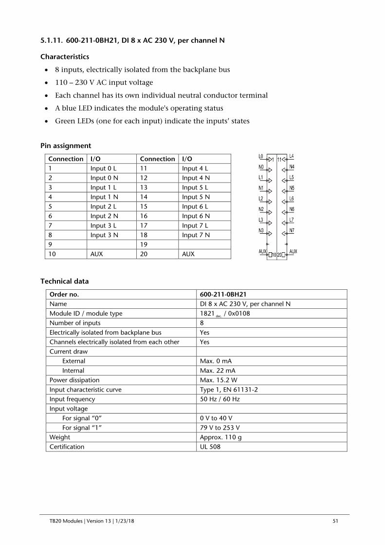
5.1.11. 600-211-0BH21, DI 8 x AC 230 V, per channel N
Characteristics
• 8 inputs, electrically isolated from the backplane bus
• 110 – 230 V AC input voltage
• Each channel has its own individual neutral conductor terminal
• A blue LED indicates the module's operating status
• Green LEDs (one for each input) indicate the inputs’ states
Pin assignment
Technical data
Order no. 600-211-0BH21 Name DI 8 x AC 230 V, per channel N Module ID / module type 1821 dec. / 0x0108 Number of inputs 8 Electrically isolated from backplane bus Yes Channels electrically isolated from each other Yes Current draw External Max. 0 mA Internal Max. 22 mA Power dissipation Max. 15.2 W Input characteristic curve Type 1, EN 61131-2 Input frequency 50 Hz / 60 Hz Input voltage For signal “0” 0 V to 40 V For signal “1” 79 V to 253 V Weight Approx. 110 g Certification UL 508
Connection I/O Connection I/O 1 Input 0 L 11 Input 4 L 2 Input 0 N 12 Input 4 N 3 Input 1 L 13 Input 5 L 4 Input 1 N 14 Input 5 N 5 Input 2 L 15 Input 6 L 6 Input 2 N 16 Input 6 N 7 Input 3 L 17 Input 7 L 8 Input 3 N 18 Input 7 N 9 19 10 AUX 20 AUX

TB20 Modules | Version 13 | 1/23/18 52
5.2. Digital output modules
5.2.1. 600-220-0AB01, DO 2 x DC 24 V, 500 mA
Characteristics
• 2 outputs, electrically isolated from the backplane bus
• 24 V DC output voltage
• 500 mA output voltage per channel
• A blue LED indicates the module's operating status
• Green LEDs (one for each output) indicate the outputs’ states
Pin assignment
Technical data
Order no. 600-220-0AB01 Name DO 2 x DC 24 V, 500 mA Module ID / module type 2200 dec. / 0x0120 Number of outputs 2 Electrically isolated from backplane bus Yes Channels electrically isolated from each other No Supply voltage UP, US Rated 24 V DC Ripple USS Max. 3.6 V Permissible range (with ripple) 20 ... 30 V Voltage for t < 10 ms 50 V Output current Rated 500 mA Leakage current Max. 0.5 mA Current draw External Max. 10 mA + load Internal Max. 27.5 mA Power dissipation Max. 0.7 W Output short-circuit protection Electronic, for each individual channel Inductive cutoff voltage limit -48 V Weight Approx. 70 g Certification UL 508
Connection I/O 1 Output 0 2 Output 1 3 GND 4 GND 5 L+, 24 VDC 6 L+, 24 VDC 7 AUX 8 AUX 9 L+, 24 VDC 10 AUX

TB20 Modules | Version 13 | 1/23/18 53
5.2.2. 600-220-0AD01, DO 4 x DC 24 V, 500 mA
Characteristics
• 4 outputs, electrically isolated from the backplane bus
• 24 V DC output voltage
• 500 mA output voltage per channel
• A blue LED indicates the module's operating status
• Green LEDs (one for each output) indicate the outputs’ states
Pin assignment
Technical data
Order no. 600-220-0AD01 Name DO 4 x DC 24 V, 500 mA Module ID / module type 2400 dec. / 0x0140 Number of outputs 4 Electrically isolated from backplane bus Yes Channels electrically isolated from each other No Supply voltage UP, US Rated 24 V DC Ripple USS Max. 3.6 V Permissible range (with ripple) 20 ... 30 V Voltage for t < 10 ms 50 V Output current Rated 500 mA Leakage current Max. 0.5 mA Current draw External Max. 20 mA + load Internal Max. 30 mA Power dissipation Max. 1.0 W Output short-circuit protection Electronic, for each individual channel Inductive cutoff voltage limit -48 V Weight Approx. 70 g Certification UL 508
Connection I/O 1 Output 0 2 Output 1 3 Output 2 4 Output 3 5 L+, 24 VDC 6 L+, 24 VDC 7 AUX 8 AUX 9 L+, 24 VDC 10 AUX

TB20 Modules | Version 13 | 1/23/18 54
5.2.3. 600-220-0AH01, DO 8 x DC 24 V, 500 mA
Characteristics
• 8 outputs, electrically isolated from the backplane bus
• 24 V DC output voltage
• 500 mA output voltage per channel
• A blue LED indicates the module's operating status
• Green LEDs (one for each output) indicate the outputs’ states
Pin assignment
Technical data
Order no. 600-220-0AH01 Name DO 8 x DC 24 V, 500 mA Module ID / module type 2800 dec. / 0x0180 Number of outputs 8 Electrically isolated from backplane bus Yes Channels electrically isolated from each other No Supply voltage UP, US Rated 24 V DC Ripple USS Max. 3.6 V Permissible range (with ripple) 20 ... 30 V Voltage for t < 10 ms 50 V Output current Rated 500 mA Leakage current Max. 0.5 mA Current draw External Max. 40 mA + load Internal Max. 35 mA Power dissipation Max. 2.5 W Output short-circuit protection Electronic, for each individual channel Inductive cutoff voltage limit -48 V Weight Approx. 70 g Certification UL 508
Connection I/O 1 Output 0 2 Output 1 3 Output 2 4 Output 3 5 Output 4 6 Output 5 7 Output 6 8 Output 7 9 L+, 24 VDC 10 AUX
TB20 Modules | Version 13 | 1/23/18 55
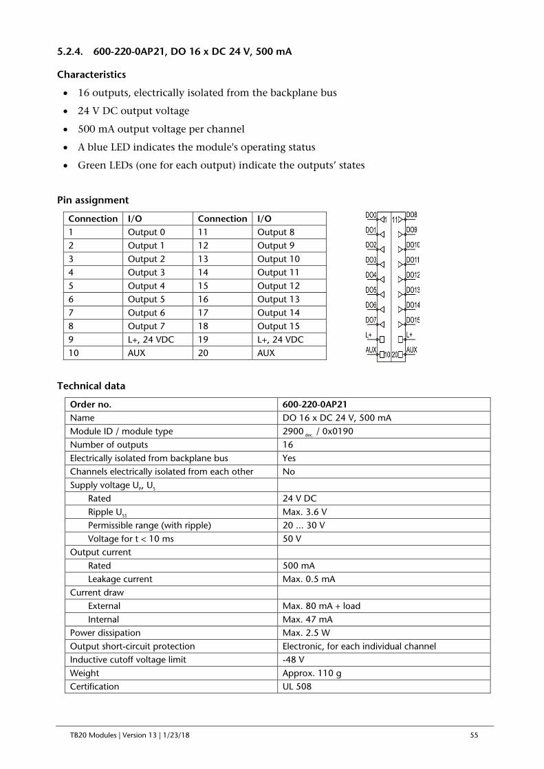
5.2.4. 600-220-0AP21, DO 16 x DC 24 V, 500 mA
Characteristics
• 16 outputs, electrically isolated from the backplane bus
• 24 V DC output voltage
• 500 mA output voltage per channel
• A blue LED indicates the module's operating status
• Green LEDs (one for each output) indicate the outputs’ states
Pin assignment
Technical data
Order no. 600-220-0AP21 Name DO 16 x DC 24 V, 500 mA Module ID / module type 2900 dec. / 0x0190 Number of outputs 16 Electrically isolated from backplane bus Yes Channels electrically isolated from each other No Supply voltage UP, US Rated 24 V DC Ripple USS Max. 3.6 V Permissible range (with ripple) 20 ... 30 V Voltage for t < 10 ms 50 V Output current Rated 500 mA Leakage current Max. 0.5 mA Current draw External Max. 80 mA + load Internal Max. 47 mA Power dissipation Max. 2.5 W Output short-circuit protection Electronic, for each individual channel Inductive cutoff voltage limit -48 V Weight Approx. 110 g Certification UL 508
Connection I/O Connection I/O 1 Output 0 11 Output 8 2 Output 1 12 Output 9 3 Output 2 13 Output 10 4 Output 3 14 Output 11 5 Output 4 15 Output 12 6 Output 5 16 Output 13 7 Output 6 17 Output 14 8 Output 7 18 Output 15 9 L+, 24 VDC 19 L+, 24 VDC 10 AUX 20 AUX

TB20 Modules | Version 13 | 1/23/18 56
5.2.5. 600-220-0DH01, DO 8 x DC 24 V, 300 mA, sink
Characteristics
• 8 outputs, electrically isolated from the backplane bus
• 300 mA output voltage per channel
• A blue LED indicates the module's operating status
• Green LEDs (one for each output) indicate the outputs’ states
Pin assignment
Technical data
Order no. 600-220-0DH01 Name DO 8 x DC 24 V, 300 mA, sink Module ID / module type 2801 dec. / 0x0180 Number of outputs 8 Electrically isolated from backplane bus Yes Channels electrically isolated from each other No Supply voltage UP, US Rated -24 V DC Ripple USS Max. 3.6 V Permissible range (with ripple) 20 ... 30 V Voltage for t < 10 ms 50 V Output current Rated 300 mA Leakage current Max. 0.5 mA Current draw External Max. 40 mA + load Internal Max. 35 mA Power dissipation Max. 2.5 W Output short-circuit protection Electronic, for each individual channel Inductive cutoff voltage limit -48 V Weight Approx. 70 g
1
10
GND
DO5
DO4
DO3
DO2
DO1
DO0
AUX
DO6
DO7
Connection I/O 1 Output 0 2 Output 1 3 Output 2 4 Output 3 5 Output 4 6 Output 5 7 Output 6 8 Output 7 9 L+, 24 VDC 10 AUX

TB20 Modules | Version 13 | 1/23/18 57
5.2.6. 600-220-0DP21, DO 16 x DC 24 V, 300 mA, sink
Characteristics
• 16 outputs, electrically isolated from the backplane bus
• 24 V DC output voltage
• 500 mA output voltage per channel
• A blue LED indicates the module's operating status
• Green LEDs (one for each output) indicate the outputs’ states
Pin assignment
Technical data
Order no. 600-220-0DP21 Name DO 16 x DC 24 V, 300 mA, sink Module ID / module type 2901 dec. / 0x0190 Number of outputs 16 Electrically isolated from backplane bus Yes Channels electrically isolated from each other No Supply voltage UP, US Rated -24 V DC Ripple USS Max. 3.6 V Permissible range (with ripple) 20 ... 30 V Voltage for t < 10 ms 50 V Output current Rated 300 mA Leakage current Max. 0.5 mA Current draw External Max. 80 mA + load Internal Max. 47 mA Power dissipation Max. 2.5 W Output short-circuit protection Electronic, for each individual channel Inductive cutoff voltage limit -48 V Weight Approx. 110 g
GND
DO7
DO6
DO5
DO4
DO3
DO2
DO1
DO0
AUX
GND
AUX
DO15
DO14
DO13
DO12
DO11
DO10
DO9
DO8
10
1
20
11Connection I/O Connection I/O 1 Output 0 11 Output 8 2 Output 1 12 Output 9 3 Output 2 13 Output 10 4 Output 3 14 Output 11 5 Output 4 15 Output 12 6 Output 5 16 Output 13 7 Output 6 17 Output 14 8 Output 7 18 Output 15 9 L+, 24 VDC 19 L+, 24 VDC 10 AUX 20 AUX

TB20 Modules | Version 13 | 1/23/18 58
5.2.7. 600-220-7AD01, DO 4 x DC 24 V, 700 mA, High Feature
Characteristics
• 4 outputs, electrically isolated from the backplane bus
• 24 V DC output voltage
• 700 mA output voltage per channel
• A blue LED indicates the module's operating status
• Green/red LEDs indicate the outputs’ states
• 24 V load voltage monitoring and diagnosis
• Short circuit to GND monitoring and diagnosis for each individual channel
• Channel status information in input image table
Pin assignment
Channel LED signals
Off = Output off
Solid green light = Output on
Solid red light = 24 V load voltage (L+) missing
Flashing red light = Short circuit to GND detected
Output area (1 byte)
7 6 5 4 3 2 1 0
Byte 0 - - - - DO 3 DO 2 DO 1 DO 0
Input area (1 byte)
7 6 5 4 3 2 1 0
Byte 0 Status DO 3 Status DO 2 Status DO 1 Status DO 0
Status DO: 00 = OK / 01 = short circuit to GND / 10 = 24 V load voltage (L+) missing
Parameters for the module
Diagnostic alarm: ON / OFF
Connection I/O 1 Output 0 2 Output 1 3 Output 2 4 Output 3 5 GND 6 GND 7 GND 8 GND 9 L+, 24 VDC 10 AUX

TB20 Modules | Version 13 | 1/23/18 59
Parameters for each channel
Behavior at CPU-STOP: Output Off / Output On / Keep last value
Pulse lengthening (0 - 255 in 5ms increments)
Technical data
Order no. 600-220-7AD01 Name DO 4 x DC 24 V, 700 mA, High Feature Module ID / module type 2410 dec. / 0x1140 Number of outputs 4 Electrically isolated from backplane bus Yes Channels electrically isolated from each other No Supply voltage UP, US Rated 24 V DC Ripple USS Max. 3.6 V Permissible range (with ripple) 20 ... 30 V Voltage for t < 10 ms 50 V Output current Rated 700 mA Leakage current Max. 0.5 mA Current draw External Max. 20 mA + load Internal Max. 30 mA Power dissipation Max. 1.0 W
Diagnoses No external reference voltage (load voltage L+) Short circuit to GND Parameter assignment error
Output short-circuit protection Electronic, for each individual channel Inductive cutoff voltage limit -48 V Weight Approx. 70 g Certification UL 508

TB20 Modules | Version 13 | 1/23/18 60
5.2.8. 600-220-7AH01, DO 8 x DC 24 V, 700 mA, High Feature
Characteristics
• 8 outputs, electrically isolated from the backplane bus
• 24 V DC output voltage
• 700 mA output voltage per channel
• A blue LED indicates the module's operating status
• Green/red LEDs indicate the outputs’ states
• 24 V load voltage monitoring and diagnosis
• Short circuit to GND monitoring and diagnosis for each individual channel
• Channel status information in input image table
Pin assignment
Channel LED signals
Off = Output off
Solid green light = Output on
Solid red light = 24 V load voltage (L+) missing
Flashing red light = Short circuit to GND detected
Output area (1 byte)
7 6 5 4 3 2 1 0
Byte 0 DO 7 DO 6 DO 5 DO 4 DO 3 DO 2 DO 1 DO 0
Input area (2 bytes)
7 6 5 4 3 2 1 0
Byte 0 Status DO 3 Status DO 2 Status DO 1 Status DO 0
Byte 1 Status DO 7 Status DO 6 Status DO 5 Status DO 4
Status DO: 00 = OK / 01 = short circuit to GND / 10 = 24 V load voltage (L+) missing
Connection I/O 1 Output 0 2 Output 1 3 Output 2 4 Output 3 5 Output 4 6 Output 5 7 Output 6 8 Output 7 9 L+, 24 VDC 10 AUX

TB20 Modules | Version 13 | 1/23/18 61
Parameters for the module
Diagnostic alarm: ON / OFF
Parameters for each channel
Behavior at CPU-STOP: Output Off / Output On / Keep last value
Pulse lengthening (0 - 255 in 5ms increments)
Technical data
Order no. 600-220-7AH01 Name DO 8 x DC 24 V, 700 mA, High Feature Module ID / module type 2810 dec. / 0x1180 Number of outputs 8 Electrically isolated from backplane bus Yes Channels electrically isolated from each other No Supply voltage UP, US Rated 24 V DC Ripple USS Max. 3.6 V Permissible range (with ripple) 20 ... 30 V Voltage for t < 10 ms 50 V Output current Rated 700 mA Leakage current Max. 0.5 mA Current draw External Max. 40 mA + load Internal Max. 35 mA Power dissipation Max. 2.5 W
Diagnoses No external reference voltage (load voltage L+) Short circuit to GND Parameter assignment error
Output short-circuit protection Electronic, for each individual channel Inductive cutoff voltage limit -48 V Weight Approx. 70 g Certification UL 508

TB20 Modules | Version 13 | 1/23/18 62
5.2.9. 600-220-7AP21, DO 16 x DC 24 V, 700 mA, High Feature
Characteristics
• 16 outputs, electrically isolated from the backplane bus
• 24 V DC output voltage
• 700 mA output voltage per channel
• A blue LED indicates the module's operating status
• Green/red LEDs indicate the outputs’ states
• 24 V load voltage monitoring and diagnosis
• Short circuit to GND monitoring and diagnosis for each individual channel
• Channel status information in input image table
Pin assignment
Channel LED signals
Off = Output off
Solid green light = Output on
Solid red light = 24 V load voltage (L+) missing
Flashing red light = Short circuit to GND detected
Parameters for the module
Diagnostic alarm: ON / OFF
Parameters for each channel
Behavior at CPU-STOP: Output Off / Output On / Keep last value
Pulse lengthening (0 - 255 in 5ms increments)
Output area (2 byte)
7 6 5 4 3 2 1 0
Byte 0 DO 7 DO 6 DO 5 DO 4 DO 3 DO 2 DO 1 DO 0
Byte 1 DO 15 DO 14 DO 13 DO 12 DO 11 DO 10 DO 9 DO 8
Connection I/O Connection I/O 1 Output 0 11 Output 8 2 Output 1 12 Output 9 3 Output 2 13 Output 10 4 Output 3 14 Output 11 5 Output 4 15 Output 12 6 Output 5 16 Output 13 7 Output 6 17 Output 14 8 Output 7 18 Output 15 9 L+, 24 VDC 19 L+, 24 VDC 10 AUX 20 AUX

TB20 Modules | Version 13 | 1/23/18 63
Input area (4 bytes)
7 6 5 4 3 2 1 0
Byte 0 Status DO 3 Status DO 2 Status DO 1 Status DO 0
Byte 1 Status DO 7 Status DO 6 Status DO 5 Status DO 4
Byte 2 Status DO 11 Status DO 10 Status DO 9 Status DO 8
Byte 3 Status DO 15 Status DO 14 Status DO 13 Status DO 12
Status DO: 00 = OK / 01 = short circuit to GND / 10 = 24 V load voltage (L+) missing
Technical specifications
Order no. 600-220-0AP21 Name DO 16 x DC 24 V, 500 mA Module ID / module type 2910 dec. / 0x1190 Number of outputs 16 Electrically isolated from backplane bus Yes Channels electrically isolated from each other No Supply voltage UP, US Rated 24 V DC Ripple USS Max. 3.6 V Permissible range (with ripple) 20 ... 30 V Voltage for t < 10 ms 50 V Output current Rated 700 mA Leakage current Max. 0.5 mA Current draw External Max. 80 mA + load Internal Max. 47 mA Power dissipation Max. 2.5 W
Diagnoses No external reference voltage (load voltage L+) Short circuit to GND Parameter assignment error
Output short-circuit protection Electronic, for each individual channel Inductive cutoff voltage limit -48 V Weight Approx. 110 g Certification UL 508

TB20 Modules | Version 13 | 1/23/18 64
5.2.10. 600-220-0BB01, DO 2 x DC 24 V, 2 A
Characteristics
• 2 outputs, electrically isolated from the backplane bus
• 24 V DC output voltage
• 2 A output voltage per channel
• A blue LED indicates the module's operating status
• Green LEDs (one for each output) indicate the outputs’ states
Pin assignment
Technical data
Order no. 600-220-0BB01 Name DO 2 x DC 24 V, 2 A Module ID / module type 2220 dec. /0x0120 Number of outputs 2 Electrically isolated from backplane bus Yes Channels electrically isolated from each other No Supply voltage UP, US Rated 24 V DC Ripple USS Max. 3.6 V Permissible range (with ripple) 20 ... 30 V Voltage for t < 10 ms 50 V Output current Rated 2 A Leakage current Max. 0.5 mA Current draw External Max. 20 mA + load Internal Max. 30 mA Power dissipation Max. 0.7 W Output short-circuit protection Electronic, for each individual channel Inductive cutoff voltage limit -48 V Weight Approx. 70 g Certification UL 508
Connection I/O 1 Output 0 2 Output 1 3 GND 4 GND 5 L+, 24 VDC 6 L+, 24 VDC 7 AUX 8 AUX 9 L+, 24 VDC 10 AUX

TB20 Modules | Version 13 | 1/23/18 65
5.2.11. 600-220-0BD01, DO 4 x DC 24 V, 2 A
Characteristics
• 4 outputs, electrically isolated from the backplane bus
• 24 V DC output voltage
• 2 A output voltage per channel
• A blue LED indicates the module's operating status
• Green LEDs (one for each output) indicate the outputs’ states
Pin assignment
Technical data
Order no. 600-220-0BD01 Name DO 4 x DC 24 V, 2 A Module ID / module type 2420dec. / 0x0140 Number of outputs 4 Electrically isolated from backplane bus Yes Channels electrically isolated from each other No Supply voltage UP, US Rated 24 V DC Ripple USS Max. 3.6 V Permissible range (with ripple) 20 ... 30 V Voltage for t < 10 ms 50 V Output current Rated 2 A Leakage current Max. 0.5 mA Current draw External Max. 30 mA + load Internal Max. 30 mA Power dissipation Max. 1.1 W Output short-circuit protection Electronic, for each individual channel Inductive cutoff voltage limit -48 V Weight Approx. 70 g Certification UL 508
Connection I/O 1 Output 0 2 Output 1 3 Output 2 4 Output 3 5 L+, 24 VDC 6 L+, 24 VDC 7 AUX 8 AUX 9 L+, 24 VDC 10 AUX

TB20 Modules | Version 13 | 1/23/18 66
5.2.12. 600-222-0AB01, DO 2 x relay, AC 230 V, 5 A, changeover
Characteristics
• Dry contact switching
• Two changeover relays
• 5 A output voltage per relay
• Up to 230 V AC switching voltage per relay
• Switching operation counter: 2x input words (switching operations *1000) [optional with Profibus-DP]
• Transient filter for protection against high-frequency relay switching (10 Hz)
• A blue LED indicates the module's operating status
• Green LEDs (one for each output) indicate the outputs’ states
Pin assignment
Technical data
Order no. 600-222-0AB01 Name DO 2 x relay, AC 230 V, 5 A, changeover Module ID / module type 2260 dec. /0x0120 Number of outputs 4 (2 changeover relays) Electrically isolated from backplane bus Yes Channels electrically isolated from each other Yes Supply voltage UP, US Rated 24 V DC Ripple USS Max. 3.6 V Permissible range (with ripple) 20 ... 30 V Voltage for t < 10 ms 50 V Current draw External Max. 30 mA Internal Max. 30 mA Power dissipation Max. 1.5 W Relays 2 Max. continuous current / max. inrush current 5 A / 10 A Rated voltage / max. switching voltage 250 V AC / 400 V AC Max. switching power for utilization category AC1 1500 VA
Connection I/O 1 Relay 0, “normally closed” 2 Relay 0, “common” 3 Relay 0, “normally open” 4 n.c. 5 Relay 1, “normally closed” 6 Relay 1, “common” 7 Relay 1, “normally open” 8 n.c. 9 L+, 24 VDC 10 AUX

TB20 Modules | Version 13 | 1/23/18 67
Max. switching power for utilization category AC15 (230 VAC)
300 VA
Single-phase motor load, utilization category AC-3 – running (230 VAC)
0.185 kW
Max. switching current for utilization category DC1: 30/110/220 V
6 / 0.2 / 0.12 A
Min. switching capacity 500 mW (12 V / 10 mA) Mechanical life (AC / DC) - / 10 * 106 switching operations Electrical life for utilization category AC1 60,000 switching operations Dielectric strength, coil to contact 6 kV (8 mm) Dielectric strength across open contacts 1000 VAC Maximum switching frequency (internal protection) 10 Hz Weight Approx. 80 g Certification UL 508
5.2.13. 600-222-0AD21, DO 4 x relay, AC 230 V, 5 A, changeover
Characteristics
• Dry contact switching
• Four changeover relays
• 5 A output voltage per relay
• Up to 230 V AC switching voltage per relay
• Switching operation counter: 4x input words (switching operations *1000) [optional with Profibus-DP]
• Transient filter for protection against high-frequency relay switching (10 Hz)
• A blue LED indicates the module's operating status
• Green LEDs (one for each output) indicate the outputs’ states
Pin assignment
Connection I/O Connection I/O 1 Relay 0, “normally closed” 11 Relay 0, “normally closed” 2 Relay 0, “common” 12 Relay 0, “common” 3 Relay 0, “normally open” 13 Relay 0, “normally open” 4 n.c. 14 n.c. 5 Relay 1, “normally closed” 15 Relay 1, “normally closed” 6 Relay 1, “common” 16 Relay 1, “common” 7 Relay 1, “normally open” 17 Relay 1, “normally open” 8 n.c. 18 n.c. 9 L+, 24 VDC 19 L+, 24 VDC 10 AUX 20 AUX

TB20 Modules | Version 13 | 1/23/18 68
Technical data
Order no. 600-222-0AD21 Name DO 2 x relay, AC 230 V, 5 A, changeover Module ID / module type 2460dec. / 0x0140 Number of outputs 8 (4 changeover relays) Electrically isolated from backplane bus Yes Channels electrically isolated from each other Yes Supply voltage UP, US Rated 24 V DC Ripple USS Max. 3.6 V Permissible range (with ripple) 20 ... 30 V Voltage for t < 10 ms 50 V Current draw External Max. 60 mA Internal Max. 60 mA Power dissipation Max. 2.5 W Relays 4 Max. continuous current / max. inrush current 5 A / 10 A Rated voltage / max. switching voltage 250 V AC / 400 V AC Max. switching power for utilization category AC1 1500 VA Max. switching power for utilization category AC15 (230 VAC) 300 VA
Single-phase motor load, utilization category AC-3 – running (230 VAC) 0.185 kW
Max. switching current for utilization category DC1: 30/110/220 V 6 / 0.2 / 0.12 A
Min. switching capacity 500 mW (12 V / 10 mA) Mechanical life (AC / DC) - / 10 * 106 switching operations Electrical life for utilization category AC1 60,000 switching operations Dielectric strength, coil to contact 6 kV (8 mm) Dielectric strength across open contacts 1000 VAC Maximum switching frequency (internal protection) 10 Hz Weight Approx. 120 g Certification UL 508

TB20 Modules | Version 13 | 1/23/18 69
5.3. Digital Input/Output Modules
5.3.1. 600-230-0AD01, DIO 2 x In / 2 x Out DC 24 V, 500 mA
Characteristics
• 2 inputs, electrically isolated from the backplane bus
• 24 V DC input voltage
• Can accommodate 2-wire proximity sensors
• 2 outputs, electrically isolated from the backplane bus
• 24 VDC output voltage
• 500 mA output voltage per channel
• A blue LED indicates the module's operating status
• Green LEDs (one for each input/output) indicate the inputs’ and outputs' states
Pin assignment
Technical data
Order no. 600-230-0AD01 Name DIO 2 x In / 2 x Out DC 24 V, 500 mA Module ID / module type 3200 dec. / 0x0122 Number of inputs 2 Input characteristic curve Type 2, EN 61131-2 Reverse polarity protection for inputs Yes Input voltage For signal "0" -3 V to 9 V For signal "1" 12 V to 30 V Number of outputs 2 Supply voltage UP, US Rated 24 V DC Ripple USS Max. 3.6 V Permissible range (with ripple) 20 ... 30 V Voltage for t < 10 ms 50 V Output current Rated 500 mA
Connection I/O 1 Input 0 2 Input 1 3 L+, 24 VDC 4 L+, 24 VDC 5 Output 0 6 Output 1 7 AUX 8 AUX 9 L+, 24 VDC 10 AUX

TB20 Modules | Version 13 | 1/23/18 70
Leakage current Max. 0.5 mA Output short-circuit protection Electronic, for each individual channel Inductive cutoff voltage limit -48 V Current draw External Max. 10 mA + load Internal Max. 25 mA Power dissipation Max. 1.2 W Electrically isolated from backplane bus Yes Channels electrically isolated from each other No Weight Approx. 70 g Certification UL 508

TB20 Modules | Version 13 | 1/23/18 71
5.3.2. 600-230-0AH01, DIO 4 x In / 4 x Out DC 24 V, 500 mA
Characteristics
• 4 inputs, electrically isolated from the backplane bus
• 24 V DC input voltage
• Can accommodate 2-wire proximity sensors
• 4 outputs, electrically isolated from the backplane bus
• 24 VDC output voltage
• 500 mA output voltage per channel
• A blue LED indicates the module's operating status
• Green LEDs (one for each input/output) indicate the inputs’ and outputs' states
Pin assignment
Technical data
Order no. 600-230-0AH01 Name DIO 4 x In / 4 x Out DC 24 V, 500 mA Module ID / module type 3400 dec. / 0x0144 Number of inputs 4 Input characteristic curve Type 2, EN 61131-2 Reverse polarity protection for inputs Yes Input voltage For signal "0" -3 V to 9 V For signal "1" 12 V to 30 V Number of outputs 4 Supply voltage UP, US Rated 24 V DC Ripple USS Max. 3.6 V Permissible range (with ripple) 20 ... 30 V Voltage for t < 10 ms 50 V Output current Rated 500 mA Leakage current Max. 0.5 mA
Connection I/O 1 Input 0 2 Input 1 3 Input 2 4 Input 3 5 Output 0 6 Output 1 7 Output 2 8 Output 3 9 L+, 24 VDC 10 AUX

TB20 Modules | Version 13 | 1/23/18 72
Output short-circuit protection Electronic, for each individual channel Inductive cutoff voltage limit -48 V Current draw External Max. 20 mA + load Internal Max. 28 mA Power dissipation Max. 1.95 W Electrically isolated from backplane bus Yes Channels electrically isolated from each other No Weight Approx. 70 g Certification UL 508
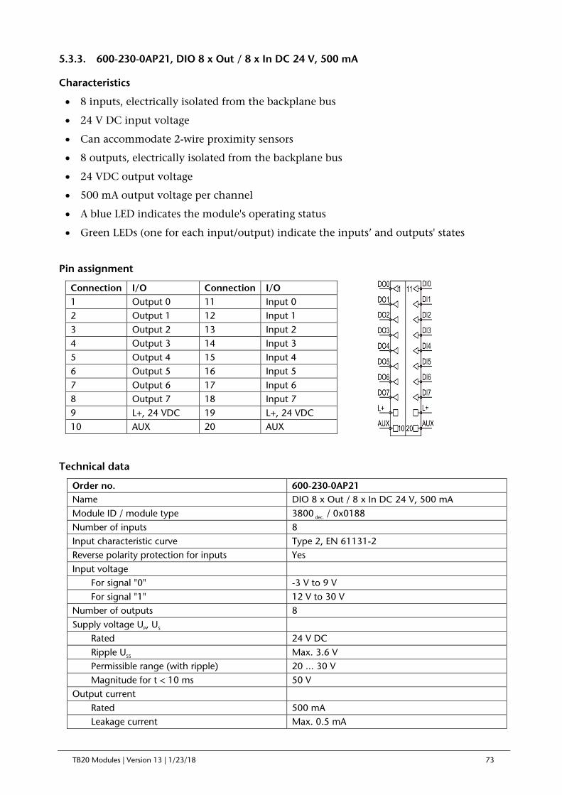
TB20 Modules | Version 13 | 1/23/18 73
5.3.3. 600-230-0AP21, DIO 8 x Out / 8 x In DC 24 V, 500 mA
Characteristics
• 8 inputs, electrically isolated from the backplane bus
• 24 V DC input voltage
• Can accommodate 2-wire proximity sensors
• 8 outputs, electrically isolated from the backplane bus
• 24 VDC output voltage
• 500 mA output voltage per channel
• A blue LED indicates the module's operating status
• Green LEDs (one for each input/output) indicate the inputs’ and outputs' states
Pin assignment
Technical data
Order no. 600-230-0AP21 Name DIO 8 x Out / 8 x In DC 24 V, 500 mA Module ID / module type 3800 dec. / 0x0188 Number of inputs 8 Input characteristic curve Type 2, EN 61131-2 Reverse polarity protection for inputs Yes Input voltage For signal "0" -3 V to 9 V For signal "1" 12 V to 30 V Number of outputs 8 Supply voltage UP, US Rated 24 V DC Ripple USS Max. 3.6 V Permissible range (with ripple) 20 ... 30 V Magnitude for t < 10 ms 50 V Output current Rated 500 mA Leakage current Max. 0.5 mA
Connection I/O Connection I/O 1 Output 0 11 Input 0 2 Output 1 12 Input 1 3 Output 2 13 Input 2 4 Output 3 14 Input 3 5 Output 4 15 Input 4 6 Output 5 16 Input 5 7 Output 6 17 Input 6 8 Output 7 18 Input 7 9 L+, 24 VDC 19 L+, 24 VDC 10 AUX 20 AUX

TB20 Modules | Version 13 | 1/23/18 74
Output short-circuit protection Electronic, for each individual channel Inductive cutoff voltage limit -48 V Current draw External Max. 40 mA + load Internal Max. 35 mA Power dissipation Max. 4.35 W Electrically isolated from backplane bus Yes Channels electrically isolated from each other No Weight Approx. 110 g Certification UL 508

TB20 Modules | Version 13 | 1/23/18 75
6. Analog modules
6.1. Analog Input Modules
6.1.1. 600-250-4AB01, AI 2 x I, 0/4-20 mA, ±20 mA, 12-bit
Characteristics
• 2 analog inputs for measuring current, electrically isolated from the backplane bus
• 2 process input words
• Measuring ranges 0 ... 20 mA, 4 ... 20 mA, ±20 mA, individually configurable for each channel
• Measurement resolution: up to 12 bits + sign
• Diagnostic messages
• Wire break detection (for 4 ...) 20 mA)
• Limit value alarms for each channel
• A bi-color LED (blue/red) indicates the module’s operating status and any malfunctions
Pin assignment
Parameters for the module
Diagnostic alarm: ON / OFF
Overflow / underflow diagnosis: ON / OFF
Format of values: Simatic S7 / Simatic S5 / INT16
Parameters for each channel
Wire break detection (for 4–20 mA only): ON / OFF
Interference frequency suppression: None / 10 Hz / 50 Hz / 60 Hz / 400 Hz
Measuring range: deactivated / 0 ... 20 mA / 4 ... 20 mA / ±20 mA
Limit value alarms enabled: ON / OFF
Upper / lower limit: 16-bit analog value (±27648)
Connection I/O 1 AI0 + 2 AI0 - 3 AI1 + 4 AI1 - 5 L+, 24 VDC 6 L+, 24 VDC 7 L-, GND 8 L-, GND 9 Mana 10 AUX

TB20 Modules | Version 13 | 1/23/18 76
Technical specifications
Order no. 600-250-4AB01 Name AI 2 x I 0/4–20 mA, ±20 mA, 12-bit Module ID / module type 4200 dec. / 0x0202 Number of inputs 2 Electrically isolated from backplane bus Yes Channels electrically isolated from each other No Current draw External Not needed Internal Max. 95 mA Power dissipation Max. 0.7 W
Measuring ranges / load resistance 0 ... 20 mA / 50 ohms 4 ... 20 mA / 50 ohms ±20 mA / 50 ohms
Measurement resolution 12 bits + sign Measuring method Integration Interference frequency suppression None / 10 Hz / 50 Hz / 60 Hz / 400 Hz
Refresh rate / conversion rate
Number of active channels x conversion time + 16 ms for wire break detection for each channel when activated The conversion time depends on the interference frequency suppression: None: 8 ms 400 Hz: 45 ms 60 Hz: 109 ms 50 Hz: 128 ms 10 Hz: 342 ms
Diagnoses
Upper measuring limit exceeded (overflow) Lower measuring limit fallen below (underflow) Wire break (only for 4 ...) 20 mA) Configuration error
Process alarms Upper and lower limit per channel Error limits
Operational error limit ±0.5% within the entire temperature range, relative to the nominal range
Basic error limit ±0.3%, operational error limit at 25°C, relative to the nominal range
Temperature error ±0.005%/K, relative to the nominal range Linearity error ±0.05%/K, relative to the nominal range Repeating accuracy in steady state at 25 °C ±0.05%/K, relative to the nominal range Parameter configuration length 12 bytes General error indicator Red LED Weight Approx. 70 g Certification UL 508

TB20 Modules | Version 13 | 1/23/18 77
6.1.2. 600-250-4AD01, AI 4 x I, 0/4-20 mA, ±20 mA, 12-bit
Characteristics
• 4 analog inputs for measuring current, electrically isolated from the backplane bus
• 4 process input words
• Measuring ranges 0 ... 20 mA, 4 ... 20 mA, ±20 mA, individually configurable for each channel
• Measurement resolution: up to 12 bits + sign
• Diagnostic messages
• Wire break detection (for 4 ... 20 mA)
• Limit value alarms for each channel
• A bi-color LED (blue/red) indicates the module’s operating status and any malfunctions
Pin assignment
Parameters for the module
Diagnostic alarm: ON / OFF
Overflow / underflow diagnosis: ON / OFF
Format of values: Simatic S7 / Simatic S5 / INT16
Parameters for each channel
Wire break detection (for 4–20 mA only): ON / OFF
Interference frequency suppression: None / 10 Hz / 50 Hz / 60 Hz / 400 Hz
Measuring range: deactivated / 0 ... 20 mA / 4 ... 20 mA / ±20 mA
Limit value alarms enabled: ON / OFF
Upper / lower limit: 16-bit analog value (±27648)
Connection I/O 1 AI0 + 2 AI0 - 3 AI1 + 4 AI1 - 5 AI2 + 6 AI2 - 7 AI3 + 8 AI3 - 9 Mana 10 AUX

TB20 Modules | Version 13 | 1/23/18 78
Technical specifications
Order no. 600-250-4AD01 Name AI 4 x I 0/4–20 mA, ±20 mA, 12-bit Module ID / module type 4400 dec. / 0x0204 Number of inputs 4 Electrically isolated from backplane bus Yes Channels electrically isolated from each other No Current draw External Not needed Internal Max. 95 mA Power dissipation Max. 0.7 W
Measuring ranges / load resistance 0 ... 20 mA / 50 ohms 4 ... 20 mA / 50 ohms ±20 mA / 50 ohms
Measurement resolution 12 bits + sign Measuring method Integration Interference frequency suppression None / 10 Hz / 50 Hz / 60 Hz / 400 Hz
Refresh rate / conversion rate
Number of active channels x conversion time + 16 ms for wire break detection for each channel when activated The conversion time depends on the interference frequency suppression: None: 8 ms 400 Hz: 45 ms 60 Hz: 109 ms 50 Hz: 128 ms 10 Hz: 342 ms
Diagnoses
Upper measuring limit exceeded (overflow) Lower measuring limit fallen below (underflow) Wire break (for 4–20 mA only) Parameter assignment error
Process alarms Upper and lower limit per channel Error limits
Operational error limit ±0.5% within the entire temperature range, relative to the nominal range
Basic error limit ±0.3%, operational error limit at 25 °C, relative to the nominal range
Temperature error ±0.005%/K, relative to the nominal range Linearity error ±0.05%/K, relative to the nominal range Repeating accuracy in steady state at 25 °C ±0.05%/K, relative to the nominal range Parameter configuration length 22 bytes General error indicator Red LED Weight Approx. 70 g Certification UL 508

TB20 Modules | Version 13 | 1/23/18 79
6.1.3. 600-250-7BB01, AI 2 x I, 0/4-20 mA, ±20 mA, Iso., 16-bit
Characteristics
• 2 analog inputs for measuring current
• Channels electrically isolated from each other and from the backplane bus
• 2 process input words
• Measuring ranges 0 ... 20 mA, 4 ... 20 mA, ±20 mA, individually configurable for each channel
• Measurement resolution: up to 15 bits + sign
• Diagnostic messages
• Red/green bi-color LEDs (one for each channel) indicate the channels’ states
• Wire break detection (for 4 ... 20 mA)
• Limit value alarms for each channel
• A bi-color LED (blue/red) indicates the module’s operating status and any malfunctions
Pin assignment
Channel LED signals:
Flashing red light = Parameter assignment error on channel
Solid red light = Reading overflow/underflow or wire break
Flashing green light = Reading within overdrive range
Solid green light = Channel configured, normal reading
Off = Channel disabled or module not yet configured
Parameters for the module
Diagnostic alarm: ON / OFF
Overflow / underflow diagnosis: ON / OFF
Format of values: Simatic S7 / Simatic S5 / INT16
Parameters for each channel
Wire break detection (for 4–20 mA only): ON / OFF
Connection I/O 1 AI0 + 2 AI0 - 3 AI1 + 4 AI1 - 5 n.c. 6 n.c. 7 n.c. 8 n.c. 9 n.c. 10 AUX

TB20 Modules | Version 13 | 1/23/18 80
Interference frequency suppression: None / 10 Hz / 50 Hz / 60 Hz / 400 Hz
Measuring range: deactivated / 0 ... 20 mA / 4 ... 20 mA / ±20 mA
Limit value alarms enabled: ON / OFF
Upper / lower limit: 16-bit analog value (±27648)
Technical specifications
Order no. 600-250-7BB01 Name AI 2 x I, 0/4–20 mA, ±20 mA, Iso., 16-bit Module ID / module type 4210 dec. / 0x0202 Number of inputs 2 Electrically isolated from backplane bus Yes Channels electrically isolated from each other Yes Current draw External Not needed Internal Max. 140 mA Power dissipation Max. 1 W
Measuring ranges / load resistance 0 ... 20 mA / 50 ohms 4 ... 20 mA / 50 ohms ±20 mA / 50 ohms
Measurement resolution 15 bits + sign Measuring method Integration Interference frequency suppression None / 10 Hz / 50 Hz / 60 Hz / 400 Hz
Refresh rate / conversion rate
Depends on the interference frequency suppression setting being used: None: 2 ms 400 Hz: 8 ms 60 Hz: 51 ms 50 Hz: 60 ms 10 Hz: 160 ms
Diagnoses
Upper measuring limit exceeded (overflow) Lower measuring limit fallen below (underflow) Wire break (for 4-20 mA only) Configuration error
Process alarms Upper and lower limit per channel Error limits
Operational error limit ±0.2% within the entire temperature range, relative to the nominal range
Basic error limit ±0.1%, operational error limit at 25°C, relative to the nominal range
Temperature error ±0.005%/K, relative to the nominal range Linearity error ±0.05%/K, relative to the nominal range Repeating accuracy in steady state at 25 °C ±0.05%/K, relative to the nominal range Parameter configuration length 13 bytes General error indicator Red LED Weight Approx. 70 g Certification UL 508

TB20 Modules | Version 13 | 1/23/18 81
6.1.4. 600-250-7BD01, AI 4 x I, 0/4-20 mA, ±20 mA, Iso., 16-bit
Characteristics
• 4 analog inputs for measuring current
• Channels electrically isolated from each other and from the backplane bus
• 4 process input words
• Measuring ranges 0 ... 20 mA, 4 ... 20 mA, ±20 mA, individually configurable for each channel
• Measurement resolution: up to 15 bits + sign
• Diagnostic messages
• Red/green bi-color LEDs (one for each channel) indicate the channels’ states
• Wire break detection (for 4 ... 20 mA)
• Limit value alarms for each channel
• A bi-color LED (blue/red) indicates the module’s operating status and any malfunctions
Pin assignment
Channel LED signals:
Flashing red light = Parameter assignment error on channel
Solid red light = Reading overflow/underflow or wire break
Flashing green light = Reading within overdrive range
Solid green light = Channel configured, normal reading
Off = Channel disabled or module not yet configured
Parameters for the module
Diagnostic alarm: ON / OFF
Overflow / underflow diagnosis: ON / OFF
Format of values: Simatic S7 / Simatic S5 / INT16
Connection I/O 1 AI0 + 2 AI0 - 3 AI1 + 4 AI1 - 5 AI2 + 6 AI2 - 7 AI3 + 8 AI3 - 9 n.c. 10 AUX
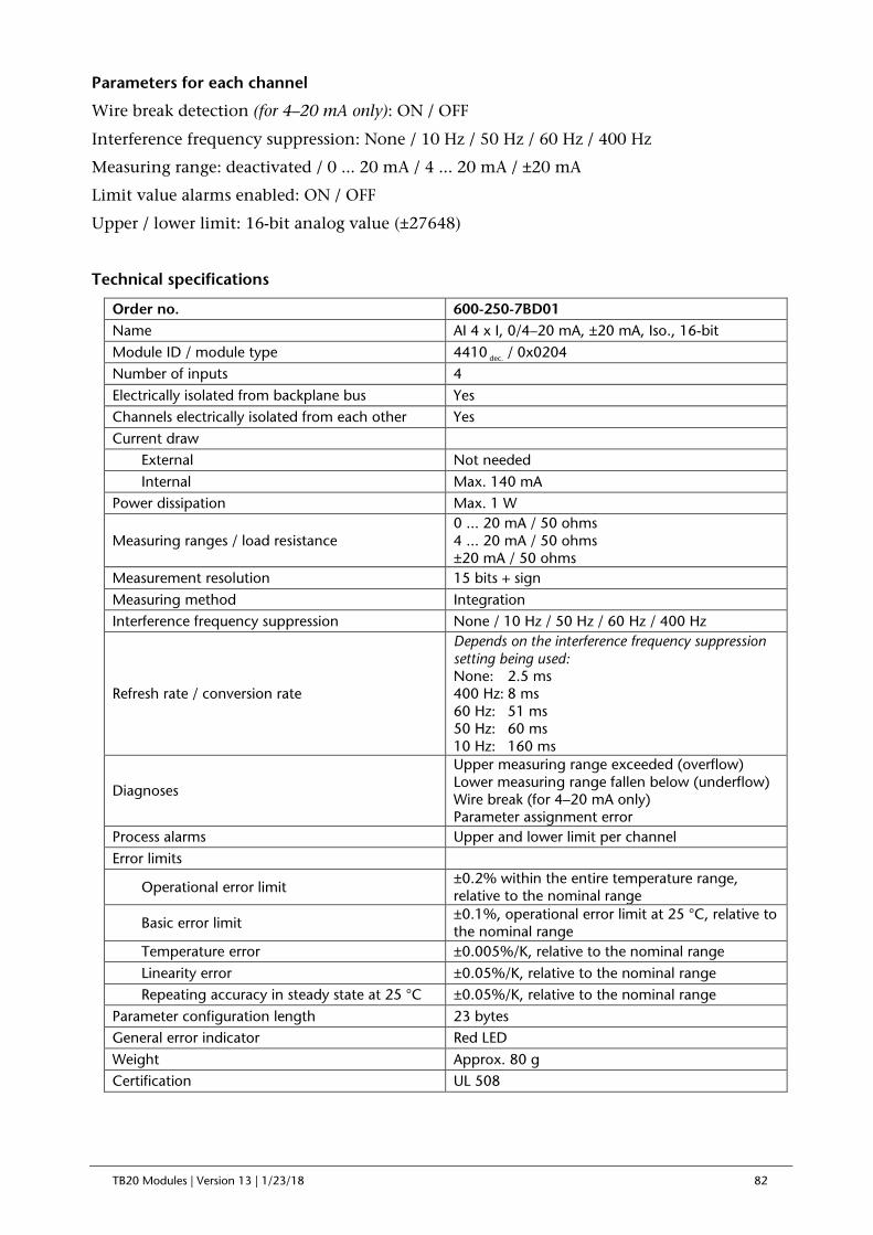
TB20 Modules | Version 13 | 1/23/18 82
Parameters for each channel
Wire break detection (for 4–20 mA only): ON / OFF
Interference frequency suppression: None / 10 Hz / 50 Hz / 60 Hz / 400 Hz
Measuring range: deactivated / 0 ... 20 mA / 4 ... 20 mA / ±20 mA
Limit value alarms enabled: ON / OFF
Upper / lower limit: 16-bit analog value (±27648)
Technical specifications
Order no. 600-250-7BD01 Name AI 4 x I, 0/4–20 mA, ±20 mA, Iso., 16-bit Module ID / module type 4410 dec. / 0x0204 Number of inputs 4 Electrically isolated from backplane bus Yes Channels electrically isolated from each other Yes Current draw External Not needed Internal Max. 140 mA Power dissipation Max. 1 W
Measuring ranges / load resistance 0 ... 20 mA / 50 ohms 4 ... 20 mA / 50 ohms ±20 mA / 50 ohms
Measurement resolution 15 bits + sign Measuring method Integration Interference frequency suppression None / 10 Hz / 50 Hz / 60 Hz / 400 Hz
Refresh rate / conversion rate
Depends on the interference frequency suppression setting being used: None: 2.5 ms 400 Hz: 8 ms 60 Hz: 51 ms 50 Hz: 60 ms 10 Hz: 160 ms
Diagnoses
Upper measuring range exceeded (overflow) Lower measuring range fallen below (underflow) Wire break (for 4–20 mA only) Parameter assignment error
Process alarms Upper and lower limit per channel Error limits
Operational error limit ±0.2% within the entire temperature range, relative to the nominal range
Basic error limit ±0.1%, operational error limit at 25 °C, relative to the nominal range
Temperature error ±0.005%/K, relative to the nominal range Linearity error ±0.05%/K, relative to the nominal range Repeating accuracy in steady state at 25 °C ±0.05%/K, relative to the nominal range Parameter configuration length 23 bytes General error indicator Red LED Weight Approx. 80 g Certification UL 508

TB20 Modules | Version 13 | 1/23/18 83
6.1.5. 600-250-7BH21, AI 8 x I, 0/4-20 mA, ±20 mA, Iso., 16-bit
Characteristics
• 8 analog inputs for measuring current
• Channels electrically isolated from each other and from the backplane bus
• 8 process input words
• Measuring ranges 0 ... 20 mA, 4 ... 20 mA, ±20 mA, individually configurable for each channel
• Measurement resolution: up to 15 bits + sign
• Red/green bi-color LEDs (one for each channel) indicate the channels’ states
• Diagnostic messages
• Wire break detection (for 4 ... 20 mA)
• Limit value alarms for each channel
• A bi-color LED (blue/red) indicates the module’s operating status and any malfunctions
Pin assignment
Channel LED signals:
Flashing red light = Parameter assignment error on channel
Solid red light = Reading overflow/underflow or wire break
Flashing green light = Reading within overdrive range
Solid green light = Channel configured, normal reading
Off = Channel disabled or module not yet configured
Parameters for the module
Diagnostic alarm: ON / OFF
Overflow / underflow diagnosis: ON / OFF
Format of values: Simatic S7 / Simatic S5 / INT16
Connection I/O Connection I/O 1 AI0 + 11 AI4 + 2 AI0 - 12 AI4 - 3 AI1 + 13 AI5 + 4 AI1 - 14 AI5 - 5 AI2 + 15 AI6 + 6 AI2 - 16 AI6 - 7 AI3 + 17 AI7 + 8 AI3 - 18 AI7 - 9 n.c. 19 n.c. 10 AUX 20 AUX

TB20 Modules | Version 13 | 1/23/18 84
Parameters for each channel
Wire break detection (for 4–20 mA only): ON / OFF
Interference frequency suppression: None / 10 Hz / 50 Hz / 60 Hz / 400 Hz
Measuring range: deactivated / 0 ... 20 mA / 4 ... 20 mA / ±20 mA
Limit value alarms enabled: ON / OFF
Upper / lower limit: 16-bit analog value (±27648)
Technical specifications
Order no. 600-250-7BH21 Name AI 8 x I, 0/4–20 mA, ±20 mA, Iso., 16-bit Module ID / module type 4810 dec. / 0x0208 Number of inputs 8 Electrically isolated from backplane bus Yes Channels electrically isolated from each other Yes Current draw External Not needed Internal Max. 140 mA Power dissipation Max. 1 W
Measuring ranges / load resistance 0 ... 20 mA / 50 ohms 4 ... 20 mA / 50 ohms ±20 mA / 50 ohms
Measurement resolution 15 bits + sign Measuring method Integration Interference frequency suppression None / 10 Hz / 50 Hz / 60 Hz / 400 Hz
Refresh rate / conversion rate
Depends on the interference frequency suppression setting being used: None: 3 ms 400 Hz: 8 ms 60 Hz: 51 ms 50 Hz: 60 ms 10 Hz: 160 ms
Diagnoses
Upper measuring limit exceeded (overflow) Lower measuring limit fallen below (underflow) Wire break (for 4–20 mA only) Parameter assignment error
Process alarms Upper and lower limit per channel Error limits
Operational error limit ±0.2% within the entire temperature range, relative to the nominal range
Basic error limit ±0.1%, operational error limit at 25 °C, relative to the nominal range
Temperature error ±0.005%/K, relative to the nominal range Linearity error ±0.05%/K, relative to the nominal range Repeating accuracy in steady state at 25 °C ±0.05%/K, relative to the nominal range Parameter configuration length 44 bytes General error indicator Red LED Weight Approx. 110 g Certification UL 508

TB20 Modules | Version 13 | 1/23/18 85
6.1.6. 600-252-4AB01, AI 2 x U, ±10 V, 0–10 V, 1–5 V, 12-bit
Characteristics
• 2 analog inputs for measuring voltage (electrically isolated from the backplane bus)
• 2 process input words
• Measuring ranges 0 ... 10 V, 1 ... 5 V, ±10 V, ±5 V, ±2.5 V, individually configurable for each channel
• Measurement resolution: up to 12 bits + sign
• Diagnostic messages
• Wire break detection (for 1 ... 5V)
• Limit value alarms for each channel
• A bi-color LED (blue/red) indicates the module’s operating status and any malfunctions
Pin assignment
Parameters for the module
Diagnostic alarm: ON / OFF
Overflow / underflow diagnosis: ON / OFF
Format of values: Simatic S7 / Simatic S5 / INT16
Parameters for each channel
Wire break detection (for 1–5 V only): ON / OFF
Interference frequency suppression: None / 10 Hz / 50 Hz / 60 Hz / 400 Hz
Measuring range: deactivated / 0 ... 10 V / 1 ... 5 V / ±10 V / ±5 V / ±2.5 V
Limit value alarms enabled: ON / OFF
Upper / lower limit: 16-bit analog value (±27648)
Connection I/O 1 AI0 + 2 AI0 - 3 AI1 + 4 AI1 - 5 L+, 24 VDC 6 L+, 24 VDC 7 L-, GND 8 L-, GND 9 Mana 10 AUX

TB20 Modules | Version 13 | 1/23/18 86
Technical specifications
Order no. 600-252-4AB01 Name AI 2 x U, ±10 V, 0–10 V, 1–5 V, 12-bit Module ID / module type 5200 dec. / 0x0202 Number of inputs 2 Electrically isolated from backplane bus Yes Channels electrically isolated from each other No Current draw External Not needed Internal Max. 95 mA Power dissipation Max. 0.7 W
Measuring ranges / load resistance
0 ... 10 V / 10 Mohms 1 … 5 V / 10 Mohms ±10 V / 10 Mohms ±5 V / 10 Mohms ±2.5 V / 10 Mohms
Measurement resolution 12 bits + sign Measuring method Integration Interference frequency suppression None / 10 Hz / 50 Hz / 60 Hz / 400 Hz
Refresh rate / conversion rate
Number of active channels x conversion time + 16 ms for wire break detection for each channel when activated The conversion time depends on the interference frequency suppression: None: 8 ms 400 Hz: 45 ms 60 Hz: 109 ms 50 Hz: 128 ms 10 Hz: 342 ms
Diagnoses
Upper measuring limit exceeded (overflow) Lower measuring limit fallen below (underflow) Wire break (for 1–5 V only) Parameter assignment error
Process alarms Upper and lower limit per channel Error limits
Operational error limit ±0.5% within the entire temperature range, relative to the nominal range
Basic error limit ±0.3%, operational error limit at 25 °C, relative to the nominal range
Temperature error ±0.005%/K, relative to the nominal range Linearity error ±0.05%/K, relative to the nominal range Repeating accuracy in steady state at 25 °C ±0.05%/K, relative to the nominal range Parameter configuration length 12 bytes General error indicator Red LED Weight Approx. 70 g Certification UL 508

TB20 Modules | Version 13 | 1/23/18 87
6.1.7. 600-252-4AD01, AI 4 x U, ±10 V, 0–10 V, 1–5 V, 12-bit
Characteristics
• 4 analog inputs for measuring voltage (electrically isolated from the backplane bus)
• 4 process input words
• Measuring ranges 0 ... 10 V, 1 ... 5 V, ±10 V, ±5 V, ±2.5 V, individually configurable for each channel
• Measurement resolution: up to 12 bits + sign
• Diagnostic messages
• Wire break detection (for 1–5 V)
• Limit value alarms for each channel
• A bi-color LED (blue/red) indicates the module’s operating status and any malfunctions
Pin assignment
Parameters for the module
Diagnostic alarm: ON / OFF
Overflow / underflow diagnosis: ON / OFF
Format of values: Simatic S7 / Simatic S5 / INT16
Parameters for each channel
Wire break detection (for 1-5V only): ON / OFF
Interference frequency suppression: None / 10 Hz / 50 Hz / 60 Hz / 400 Hz
Measuring range: deactivated / 0 ... 10 V / 1 ... 5 V / ±10 V / ±5 V / ±2.5 V
Limit value alarms enabled: ON / OFF
Upper / lower limit: 16-bit analog value (±27648)
Connection I/O 1 AI0 + 2 AI0 - 3 AI1 + 4 AI1 - 5 AI2 + 6 AI2 - 7 AI3 + 8 AI3 - 9 Mana 10 AUX

TB20 Modules | Version 13 | 1/23/18 88
Technical specifications
Order no. 600-252-4AD01 Name AI 4 x U, ±10 V, 0–10 V, 1–5 V, 12-bit Module ID / module type 5400 dec. / 0x0204 Number of inputs 4 Electrically isolated from backplane bus Yes Channels electrically isolated from each other No Current draw External Not needed Internal Max. 95 mA Power dissipation Max. 0.7 W
Measuring ranges / load resistance
0 ... 10 V / 10 Mohms 1 ... 5 V / 10 Mohms ±10 V / 10 Mohms ±5 V / 10 Mohms ±2.5 V / 10 Mohms
Measurement resolution 12 bits + sign Measuring method Integration Interference frequency suppression None / 10 Hz / 50 Hz / 60 Hz / 400 Hz
Refresh rate / conversion rate
Number of active channels x conversion time + 16 ms for wire break detection for each channel when activated The conversion time depends on the interference frequency suppression: None: 8 ms 400 Hz: 45 ms 60 Hz: 109 ms 50 Hz: 128 ms 10 Hz: 342 ms
Diagnoses
Upper measuring limit exceeded (overflow) Lower measuring limit fallen below (underflow) Wire break (for 1-5 V only) Configuration error
Process alarms Upper and lower limit per channel Error limits
Operational error limit ±0.5% within the entire temperature range, relative to the nominal range
Basic error limit ±0.3%, operational error limit at 25 °C, relative to the nominal range
Temperature error ±0.005%/K, relative to the nominal range Linearity error ±0.05%/K, relative to the nominal range Repeating accuracy in steady state at 25 °C ±0.05%/K, relative to the nominal range Parameter configuration length 22 bytes General error indicator Red LED Weight Approx. 70 g Certification UL 508

TB20 Modules | Version 13 | 1/23/18 89
6.1.8. 600-252-7BB01, AI 2 x U, ±10 V, 0–10 V, 1–5 V, Iso., 16-bit
Characteristics
• 2 analog inputs for measuring voltage
• Channels electrically isolated from each other and from the backplane bus
• 2 process input words
• Measuring ranges 0 ... 10 V, 1 ... 5 V, ±10 V, ±5 V, ±2.5 V, individually configurable for each channel
• Measurement resolution: up to 15 bits + sign
• Diagnostic messages
• Red/green bi-color LEDs (one for each channel) indicate the channels’ states
• Wire break detection (for 1 ... 5V)
• Limit value alarms for each channel
• A bi-color LED (blue/red) indicates the module’s operating status and any malfunctions
Pin assignment
Channel LED signals:
Flashing red light = Parameter assignment error on channel
Solid red light = Reading overflow/underflow or wire break
Flashing green light = Reading within overdrive range
Solid green light = Channel configured, normal reading
Off = Channel disabled or module not yet configured
Parameters for the module
Diagnostic alarm: ON / OFF
Overflow / underflow diagnosis: ON / OFF
Format of values: Simatic S7 / Simatic S5 / INT16
Connection I/O 1 AI0 + 2 AI0 - 3 AI1 + 4 AI1 - 5 n.c. 6 n.c. 7 n.c. 8 n.c. 9 n.c. 10 AUX
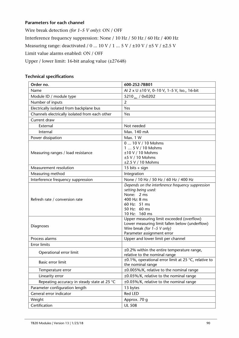
TB20 Modules | Version 13 | 1/23/18 90
Parameters for each channel
Wire break detection (for 1–5 V only): ON / OFF
Interference frequency suppression: None / 10 Hz / 50 Hz / 60 Hz / 400 Hz
Measuring range: deactivated / 0 ... 10 V / 1 ... 5 V / ±10 V / ±5 V / ±2.5 V
Limit value alarms enabled: ON / OFF
Upper / lower limit: 16-bit analog value (±27648)
Technical specifications
Order no. 600-252-7BB01 Name AI 2 x U ±10 V, 0–10 V, 1–5 V, Iso., 16-bit Module ID / module type 5210 dec. / 0x0202 Number of inputs 2 Electrically isolated from backplane bus Yes Channels electrically isolated from each other Yes Current draw External Not needed Internal Max. 140 mA Power dissipation Max. 1 W
Measuring ranges / load resistance
0 ... 10 V / 10 Mohms 1 … 5 V / 10 Mohms ±10 V / 10 Mohms ±5 V / 10 Mohms ±2.5 V / 10 Mohms
Measurement resolution 15 bits + sign Measuring method Integration Interference frequency suppression None / 10 Hz / 50 Hz / 60 Hz / 400 Hz
Refresh rate / conversion rate
Depends on the interference frequency suppression setting being used: None: 2 ms 400 Hz: 8 ms 60 Hz: 51 ms 50 Hz: 60 ms 10 Hz: 160 ms
Diagnoses
Upper measuring limit exceeded (overflow) Lower measuring limit fallen below (underflow) Wire break (for 1–5 V only) Parameter assignment error
Process alarms Upper and lower limit per channel Error limits
Operational error limit ±0.2% within the entire temperature range, relative to the nominal range
Basic error limit ±0.1%, operational error limit at 25 °C, relative to the nominal range
Temperature error ±0.005%/K, relative to the nominal range Linearity error ±0.05%/K, relative to the nominal range Repeating accuracy in steady state at 25 °C ±0.05%/K, relative to the nominal range Parameter configuration length 13 bytes General error indicator Red LED Weight Approx. 70 g Certification UL 508

TB20 Modules | Version 13 | 1/23/18 91
6.1.9. 600-252-7BD01, AI 4 x U, ±10 V, 0-10 V, 1-5 V, Iso., 16-bit
Characteristics
• 4 analog inputs for measuring voltage
• Channels electrically isolated from each other and from the backplane bus
• 4 process input words
• Measuring ranges 0 ... 10 V, 1 ... 5 V, ±10 V, ±5 V, ±2.5 V, individually configurable for each channel
• Measurement resolution: up to 15 bits + sign
• Diagnostic messages
• Red/green bi-color LEDs (one for each channel) indicate the channels’ states
• Wire break detection (for 1–5 V)
• Limit value alarms for each channel
• A bi-color LED (blue/red) indicates the module’s operating status and any malfunctions
Pin assignment
Channel LED signals:
Flashing red light = Parameter assignment error on channel
Solid red light = Reading overflow/underflow or wire break
Flashing green light = Reading within overdrive range
Solid green light = Channel configured, normal reading
Off = Channel disabled or module not yet configured
Parameters for the module
Diagnostic alarm: ON / OFF
Overflow / underflow diagnosis: ON / OFF
Format of values: Simatic S7 / Simatic S5 / INT16
Parameters for each channel
Connection I/O 1 AI0 + 2 AI0 - 3 AI1 + 4 AI1 - 5 AI2 + 6 AI2 - 7 AI3 + 8 AI3 - 9 n.c. 10 AUX

TB20 Modules | Version 13 | 1/23/18 92
Wire break detection (for 1-5V only): ON / OFF
Interference frequency suppression: None / 10 Hz / 50 Hz / 60 Hz / 400 Hz
Measuring range: deactivated / 0 ... 10 V / 1 ... 5 V / ±10 V / ±5 V / ±2.5 V
Limit value alarms enabled: ON / OFF
Upper / lower limit: 16-bit analog value (±27648)
Technical specifications
Order no. 600-252-7BD01 Name AI 4 x U ±10 V, 0–10 V, 1–5 V, Iso., 16-bit Module ID / module type 5410 dec. / 0x0204 Number of inputs 4 Electrically isolated from backplane bus Yes Channels electrically isolated from each other Yes Current draw External Not needed Internal Max. 140 mA Power dissipation Max. 1 W
Measuring ranges / load resistance
0 ... 10 V / 10 Mohms 1 ... 5 V / 10 Mohms ±10 V / 10 Mohms ±5 V / 10 Mohms ±2.5 V / 10 Mohms
Measurement resolution 15 bits + sign Measuring method Integration Interference frequency suppression None / 10 Hz / 50 Hz / 60 Hz / 400 Hz
Refresh rate / conversion rate
Depends on the interference frequency suppression setting being used: None: 2.5 ms 400 Hz: 8 ms 60 Hz: 51 ms 50 Hz: 60 ms 10 Hz: 160 ms
Diagnoses
Upper measuring limit exceeded (overflow) Lower measuring limit fallen below (underflow) Wire break (for 1-5 V only) Configuration error
Process alarms Upper and lower limit per channel Error limits
Operational error limit ±0.2% within the entire temperature range, relative to the nominal range
Basic error limit ±0.1%, operational error limit at 25 °C, relative to the nominal range
Temperature error ±0.005%/K, relative to the nominal range Linearity error ±0.05%/K, relative to the nominal range Repeating accuracy in steady state at 25 °C ±0.05%/K, relative to the nominal range Parameter configuration length 23 bytes General error indicator Red LED Weight Approx. 80 g Certification UL 508

TB20 Modules | Version 13 | 1/23/18 93
6.1.10. 600-252-7BH21, AI 8 x U, ±10 V, 0–10 V, 1–5 V, Iso., 16-bit
Characteristics
• 8 analog inputs for measuring voltage
• Channels electrically isolated from each other and from the backplane bus
• 8 process input words
• Measuring ranges 0 ... 10 V, 1 ... 5 V, ±10 V, ±5 V, ±2.5 V, individually configurable for each channel
• Measurement resolution: up to 15 bits + sign
• Diagnostic messages
• Red/green bi-color LEDs (one for each channel) indicate the channels’ states
• Wire break detection (for 1-5 V)
• Limit value alarms for each channel
• A bi-color LED (blue/red) indicates the module’s operating status and any malfunctions
Pin assignment
Channel LED signals:
Flashing red light = Parameter assignment error on channel
Solid red light = Reading overflow/underflow or wire break
Flashing green light = Reading within overdrive range
Solid green light = Channel configured, normal reading
Off = Channel disabled or module not yet configured
Parameters for the module
Diagnostic alarm: ON / OFF
Overflow / underflow diagnosis: ON / OFF
Format of values: Simatic S7 / Simatic S5 / INT16
Parameters for each channel
Wire break detection (for 1-5V only): ON / OFF
Connection I/O Connection I/O 1 AI0 + 11 AI4 + 2 AI0 - 12 AI4 - 3 AI1 + 13 AI5 + 4 AI1 - 14 AI5 - 5 AI2 + 15 AI6 + 6 AI2 - 16 AI6 - 7 AI3 + 17 AI7 + 8 AI3 - 18 AI7 - 9 n.c. 19 n.c. 10 AUX 20 AUX

TB20 Modules | Version 13 | 1/23/18 94
Interference frequency suppression: None / 10 Hz / 50 Hz / 60 Hz / 400 Hz
Measuring range: deactivated / 0 ... 10 V / 1 ... 5 V / ±10 V / ±5 V / ±2.5 V
Limit value alarms enabled: ON / OFF
Upper / lower limit: 16-bit analog value (±27648)
Technical specifications
Order no. 600-252-7BH21 Name AI 8 x U ±10 V, 0–10 V, 1–5 V, Iso., 16-bit Module ID / module type 5810 dec. / 0x0208 Number of inputs 8 Electrically isolated from backplane bus Yes Channels electrically isolated from each other Yes Current draw External Not needed Internal Max. 140 mA Power dissipation Max. 1 W
Measuring ranges / load resistance
0 ... 10 V / 10 Mohms 1 ... 5 V / 10 Mohms ±10 V / 10 Mohms ±5 V / 10 Mohms ±2.5 V / 10 Mohms
Measurement resolution 15 bits + sign Measuring method Integration Interference frequency suppression None / 10 Hz / 50 Hz / 60 Hz / 400 Hz
Refresh rate / conversion rate
Depends on the interference frequency suppression setting being used: None: 3 ms 400 Hz: 8 ms 60 Hz: 51 ms 50 Hz: 60 ms 10 Hz: 160 ms
Diagnoses
Upper measuring limit exceeded (overflow) Lower measuring limit fallen below (underflow) Wire break (for 1-5 V only) Configuration error
Process alarms Upper and lower limit per channel Error limits
Operational error limit ±0.2% within the entire temperature range, relative to the nominal range
Basic error limit ±0.1%, operational error limit at 25 °C, relative to the nominal range
Temperature error ±0.005%/K, relative to the nominal range Linearity error ±0.05%/K, relative to the nominal range Repeating accuracy in steady state at 25 °C ±0.05%/K, relative to the nominal range Parameter configuration length 44 bytes General error indicator Red LED Weight Approx. 110 g Certification UL 508

TB20 Modules | Version 13 | 1/23/18 95
6.1.11. 600-252-4CB01, AI 2 x U, ±24 V, 0–24 V, 12-bit
Characteristics
• 2 analog inputs for measuring voltage, electrically isolated from the backplane bus
• 2 process input words
• Measuring ranges 0 ... 24 V, ±24 V, individually configurable for each channel
• Measurement resolution: up to 12 bits + sign
• Diagnostic messages
• Limit value alarms for each channel
• A bi-color LED (blue/red) indicates the module’s operating status and any malfunctions
Pin assignment
Parameters for the module
Diagnostic alarm: ON / OFF
Overflow / underflow diagnosis: ON / OFF
Representation values: Simatic S7 / Simatic S5
Parameters for each channel
Interference frequency suppression: None / 10 Hz / 50 Hz / 60 Hz / 400 Hz
Measuring range: deactivated / 0 ... 24 V / ±24 V
Limit value alarms enabled: ON / OFF
Upper / lower limit: 16-bit analog value (±27648)
Connection I/O 1 AI0 + 2 AI0 - 3 AI1 + 4 AI1 - 5 L+, 24 VDC 6 L+, 24 VDC 7 L-, GND 8 L-, GND 9 Mana 10 AUX

TB20 Modules | Version 13 | 1/23/18 96
Technical specifications
Order no. 600-252-4CB01 Name AI 2 x U ±24 V, 0–24 V, 12-bit Module ID / module type 5220 dec. / 0x0202 Number of inputs 2 Electrically isolated from backplane bus Yes Channels electrically isolated from each other No Current draw External Not needed Internal Max. 95 mA Power dissipation Max. 0.7 W
Measuring ranges / load resistance 0 ... 24 V / 10 Mohms ±24 V / 10 Mohms
Measurement resolution 12 bits + sign Measuring method Integration Interference frequency suppression None / 10 Hz / 50 Hz / 60 Hz / 400 Hz
Refresh rate / conversion rate
Number of active channels x conversion time + 16 ms for wire break detection for each channel when activated The conversion time depends on the interference frequency suppression: None: 8 ms 400 Hz: 45 ms 60 Hz: 109 ms 50 Hz: 128 ms 10 Hz: 342 ms
Diagnoses Upper measuring limit exceeded (overflow) Lower measuring limit fallen below (underflow) Parameter assignment error
Process alarms Upper and lower limit per channel Error limits
Operational error limit ±0.5% within the entire temperature range, relative to the nominal range
Basic error limit ±0.3%, operational error limit at 25 °C, relative to the nominal range
Temperature error ±0.005%/K, relative to the nominal range Linearity error ±0.05%/K, relative to the nominal range Repeating accuracy in steady state at 25 °C ±0.05%/K, relative to the nominal range Parameter configuration length 12 bytes General error indicator Red LED Weight Approx. 70 g Certification UL 508

TB20 Modules | Version 13 | 1/23/18 97
6.1.12. 600-252-4CD01, AI 4 x U, ±24 V, 0–24 V, 12-bit
Characteristics
• 4 analog inputs for measuring voltage, electrically isolated from the backplane bus
• 4 process input words
• Measuring ranges 0 ... 24 V, ±24 V, individually configurable for each channel
• Measurement resolution: up to 12 bits + sign
• Diagnostic messages
• Limit value alarms for each channel
• A bi-color LED (blue/red) indicates the module’s operating status and any malfunctions
Pin assignment
Parameters for the module
Diagnostic alarm: ON / OFF
Overflow / underflow diagnosis: ON / OFF
Representation values: Simatic S7 / Simatic S5
Parameters for each channel
Interference frequency suppression: None / 10 Hz / 50 Hz / 60 Hz / 400 Hz
Measuring range: deactivated / 0 ... 24 V / ±24 V
Limit value alarms enabled: ON / OFF
Upper / lower limit: 16-bit analog value (±27648)
Connection I/O 1 AI0 + 2 AI0 - 3 AI1 + 4 AI1 - 5 AI2 + 6 AI2 - 7 AI3 + 8 AI3 - 9 Mana 10 AUX

TB20 Modules | Version 13 | 1/23/18 98
Technical specifications
Order no. 600-252-4CD01 Name AI 4 x U ±24 V, 0–24 V, 12-bit Module ID / module type 5440 dec. / 0x0204 Number of inputs 4 Electrically isolated from backplane bus Yes Channels electrically isolated from each other No Current draw External Not needed Internal Max. 95 mA Power dissipation Max. 0.7 W
Measuring ranges / load resistance 0 ... 24 V / 10 Mohms ±24 V / 10 Mohms
Measurement resolution 12 bits + sign Measuring method Integration Interference frequency suppression None / 10 Hz / 50 Hz / 60 Hz / 400 Hz
Refresh rate / conversion rate
Number of active channels x conversion time + 16 ms for wire break detection for each channel when activated The conversion time depends on the interference frequency suppression: None: 8 ms 400 Hz: 45 ms 60 Hz: 109 ms 50 Hz: 128 ms 10 Hz: 342 ms
Diagnoses Upper measuring limit exceeded (overflow) Lower measuring limit fallen below (underflow) Parameter assignment error
Process alarms Upper and lower limit per channel Error limits
Operational error limit ±0.5% within the entire temperature range, relative to the nominal range
Basic error limit ±0.3%, operational error limit at 25 °C, relative to the nominal range
Temperature error ±0.005%/K, relative to the nominal range Linearity error ±0.05%/K, relative to the nominal range Repeating accuracy in steady state at 25 °C ±0.05%/K, relative to the nominal range Parameter configuration length 22 bytes General error indicator Red LED Weight Approx. 70 g Certification UL 508

TB20 Modules | Version 13 | 1/23/18 99
6.1.13. 600-252-7DD01, AI 4 x U, ±100 V, 0-100 V, Iso., 16 bit
Characteristics
• 4 analog inputs for measuring voltage
• Channels electrically isolated from each other and from the backplane bus
• 4 process input words
• Measuring ranges 0 ... 100 V, ±100 V, individually configurable for each channel
• Measurement resolution: up to 15 bits + sign
• Diagnostic messages
• Red/green bi-color LEDs (one for each channel) indicate the channels’ states
• Limit value alarms for each channel
• A bi-color LED (blue/red) indicates the module’s operating status and any malfunctions
Pin assignment
Channel LED signals:
Flashing red light = Parameter assignment error on channel
Solid red light = Reading overflow/underflow or wire break
Flashing green light = Reading within overdrive range
Solid green light = Channel configured, normal reading
Off = Channel disabled or module not yet configured
Parameters for the module
Diagnostic alarm: ON / OFF
Overflow / underflow diagnosis: ON / OFF
Format of values: Simatic S7 / Simatic S5 / INT16
Parameters for each channel
Interference frequency suppression: None / 10 Hz / 50 Hz / 60 Hz / 400 Hz
Connection I/O 1 AI0 + 2 AI0 -
3 AI1 + 4 AI1 -
5 AI2 + 6 AI2 -
7 AI3 + 8 AI3 -
9 n.c. 10 AUX

TB20 Modules | Version 13 | 1/23/18 100
Measuring range: deactivated / 0 ... 100 V / ±100 V
Limit value alarms enabled: ON / OFF
Upper / lower limit: 16-bit analog value (±27648)
Technical specifications
Order no. 600-252-7DD01 Name AI 4 x U ±100 V, 0-100 V, Iso., 16-bit Module ID / module type 5411 dec. / 0x0204 Number of inputs 4 Electrically isolated from backplane bus Yes Channels electrically isolated from each other Yes Current draw External Not needed Internal Max. 140 mA Power dissipation Max. 1 W
Measuring ranges / load resistance 0 ... 100 V / 2 Mohms ±100 V / 2 Mohms
Measurement resolution 15 bits + sign Measuring method Integration Interference frequency suppression None / 10 Hz / 50 Hz / 60 Hz / 400 Hz
Refresh rate / conversion rate
Depends on the interference frequency suppression setting being used: None: 2.5 ms 400 Hz: 8 ms 60 Hz: 51 ms 50 Hz: 60 ms 10 Hz: 160 ms
Diagnoses Upper measuring limit exceeded (overflow) Lower measuring limit fallen below (underflow) Parameter assignment error
Process alarms Upper and lower limit per channel Error limits
Operational error limit ±0.2% within the entire temperature range, relative to the nominal range
Basic error limit ±0.1%, operational error limit at 25 °C, relative to the nominal range
Temperature error ±0.005%/K, relative to the nominal range Linearity error ±0.05%/K, relative to the nominal range Repeating accuracy in steady state at 25 °C ±0.05%/K, relative to the nominal range Parameter configuration length 23 bytes General error indicator Red LED Weight Approx. 80 g Certification UL 508

TB20 Modules | Version 13 | 1/23/18 101
6.1.14. 600-252-7DH21, AI 8 x U, ±100 V, 0-100 V, Iso., 16 bit
Characteristics
• 8 analog inputs for measuring voltage
• Channels electrically isolated from each other and from the backplane bus
• 8 process input words
• Measuring ranges 0 ... 100 V, ±100 V, individually configurable for each channel
• Measurement resolution: up to 15 bits + sign
• Diagnostic messages
• Red/green bi-color LEDs (one for each channel) indicate the channels’ states
• Limit value alarms for each channel
• A bi-color LED (blue/red) indicates the module’s operating status and any malfunctions
Pin assignment
Channel LED signals:
Flashing red light = Parameter assignment error on channel
Solid red light = Reading overflow/underflow or wire break
Flashing green light = Reading within overdrive range
Solid green light = Channel configured, normal reading
Off = Channel disabled or module not yet configured
Parameters for the module
Diagnostic alarm: ON / OFF
Overflow / underflow diagnosis: ON / OFF
Format of values: Simatic S7 / Simatic S5 / INT16
Parameters for each channel
Interference frequency suppression: None / 10 Hz / 50 Hz / 60 Hz / 400 Hz
Measuring range: deactivated / 0 ... 100 V / ±100 V
Connection I/O Connection I/O 1 AI0 + 11 AI4 + 2 AI0 - 12 AI4 - 3 AI1 + 13 AI5 + 4 AI1 - 14 AI5 - 5 AI2 + 15 AI6 + 6 AI2 - 16 AI6 - 7 AI3 + 17 AI7 + 8 AI3 - 18 AI7 - 9 n.c. 19 n.c. 10 AUX 20 AUX

TB20 Modules | Version 13 | 1/23/18 102
Limit value alarms enabled: ON / OFF
Upper / lower limit: 16-bit analog value (±27648)
Technical specifications
Order no. 600-252-7DH21 Name AI 8 x U ±100 V, 0-100 V, Iso., 16-bit Module ID / module type 5811 dec. / 0x0208 Number of inputs 8 Electrically isolated from backplane bus Yes Channels electrically isolated from each other Yes Current draw External Not needed Internal Max. 140 mA Power dissipation Max. 1 W
Measuring ranges / load resistance 0 ... 10 V / 2 Mohms ±100 V / 2 Mohms
Measurement resolution 15 bits + sign Measuring method Integration Interference frequency suppression None / 10 Hz / 50 Hz / 60 Hz / 400 Hz
Refresh rate / conversion rate
Depends on the interference frequency suppression setting being used: None: 3 ms 400 Hz: 8 ms 60 Hz: 51 ms 50 Hz: 60 ms 10 Hz: 160 ms
Diagnoses Upper measuring limit exceeded (overflow) Lower measuring limit fallen below (underflow) Parameter assignment error
Process alarms Upper and lower limit per channel Error limits
Operational error limit ±0.2% within the entire temperature range, relative to the nominal range
Basic error limit ±0.1%, operational error limit at 25 °C, relative to the nominal range
Temperature error ±0.005%/K, relative to the nominal range Linearity error ±0.05%/K, relative to the nominal range Repeating accuracy in steady state at 25 °C ±0.05%/K, relative to the nominal range Parameter configuration length 44 bytes General error indicator Red LED Weight Approx. 110 g Certification UL 508

TB20 Modules | Version 13 | 1/23/18 103
6.1.15. 600-253-4AB01, AI 1/2 x R, RTD, 16-bit, 2/3/4-wire
Characteristics
• 1/2 inputs for measuring resistance, electrically isolated from the backplane bus
• 2 process input words
• Measuring ranges 150 ohms, 300 ohms, 600 ohms, 3000 ohms, 6000 ohms, PT 100, PT 1000, Ni 100, Ni 1000, LGNi 1000, PT 100 climate (as of FW V.1.06), PT 1000 climate (as of FW V1.06), can be configured individually for each channel
• Can accommodate 2/3/4-wire sensors
• Measurement resolution: up to 15 bits + sign
• Diagnostic messages
• Wire break detection
• Limit value alarms for each channel
• A bi-color LED (blue/red) indicates the module’s operating status and any malfunctions
Pin assignment
Parameters for the module
Diagnostic alarm: ON / OFF
Overflow / underflow diagnosis: ON / OFF
Representation values: Simatic S7 / Simatic S5
Temperature unit: Celsius x 10 / Fahrenheit x 10 / Kelvin x 10
Parameters for each channel
Wire break detection: ON / OFF
Interference frequency suppression: None / 10 Hz / 50 Hz / 60 Hz / 400 Hz
Measuring ranges: 150 ohms / 300 ohms / 600 ohms / 3000 ohms / 6000 ohms / PT100 / PT1000 / Ni100 / Ni1000 / LGNi1000 / PT 100 climate / PT 1000 climate
Sensor connection: disabled / 2-wire / 3-wire (channel 0 only) / 4-wire (channel 0 only)
Limit value alarms enabled: ON / OFF
Upper / lower limit: 16-bit analog value (±27648)
Connection I/O 1 AI0 + 2 AI0 - 3 AI1 + 4 AI1 - 5 L+, 24 VDC 6 L+, 24 VDC 7 L-, GND 8 L-, GND 9 Mana 10 AUX

TB20 Modules | Version 13 | 1/23/18 104
Technical specifications
Order no. 600-253-4AB01 Name AI 1/2 x R, RTD, 16-bit, 2/3/4-wire Module ID / module type 6200 dec. / 0x0202 Number of inputs 1 / 2 Electrically isolated from backplane bus Yes Channels electrically isolated from each other No Current draw External Not needed Internal Max. 140 mA Power dissipation Max. 1.0 W
Measuring ranges
150 ohms / 300 ohms / 600 ohms / 3000 ohms / 6000 ohms PT 100 / PT 1000 Ni 100 / Ni 1000 LGNi 1000 PT 100 climate / PT 1000 climate (as of FW V1.06)
Measurement resolution 15 bits + sign Measuring method Integration Interference frequency suppression None / 10 Hz / 50 Hz / 60 Hz / 400 Hz
Refresh rate / conversion rate
Number of active channels x conversion time + 16 ms for wire break detection for each channel when activated The conversion time depends on the interference frequency suppression: None: 8 ms 400 Hz: 45 ms 60 Hz: 109 ms 50 Hz: 128 ms 10 Hz: 342 ms
Diagnoses
Upper measuring limit exceeded (overflow) Lower measuring limit fallen below (underflow) Wire break Parameter assignment error
Process alarms Upper and lower limit per channel Error limits
Operational error limit ±0.5% within the entire temperature range, relative to the nominal range
Basic error limit ±0.3%, operational error limit at 25 °C, relative to the nominal range
Temperature error ±0.005%/K, relative to the nominal range Linearity error ±0.05%/K, relative to the nominal range Repeating accuracy in steady state at 25 °C ±0.05%/K, relative to the nominal range Parameter configuration length 14 bytes General error indicator Red LED Weight Approx. 70 g Certification UL 508

TB20 Modules | Version 13 | 1/23/18 105
6.1.16. 600-253-4AD01, AI 2/4 x R, RTD, 16-bit, 2/3/4-wire
Characteristics
• 2/4 inputs for measuring resistance, electrically isolated from the backplane bus
• 4 process input words
• Measuring ranges 150 ohms, 300 ohms, 600 ohms, 3000 ohms, 6000 ohms, PT 100, PT 1000, Ni 100, Ni 1000, LGNi 1000, PT 100 climate (as of FW V.1.06), PT 1000 climate (as of FW V1.06), can be configured individually for each channel
• Can accommodate 2/3/4-wire sensors
• Measurement resolution: up to 15 bits + sign
• Diagnostic messages
• Wire break detection
• Limit value alarms for each channel
• A bi-color LED (blue/red) indicates the module’s operating status and any malfunctions
Pin assignment
Parameters for the module
Diagnostic alarm: ON / OFF
Overflow / underflow diagnosis: ON / OFF
Representation values: Simatic S7 / Simatic S5
Temperature unit: Celsius x 10 / Fahrenheit x 10 / Kelvin x 10
Parameters for each channel
Wire break detection: ON / OFF
Interference frequency suppression: None / 10 Hz / 50 Hz / 60 Hz / 400 Hz
Measuring ranges: 150 ohms / 300 ohms / 600 ohms / 3000 ohms / 6000 ohms / PT100 / PT1000 / Ni100 / Ni1000 / LGNi1000 / PT 100 climate / PT 1000 climate
Sensor connection: / 2-wire / 3-wire (channels 0&2 only) / 4-wire (channels 0&2 only)
Limit value alarms enabled: ON / OFF
Upper / lower limit: 16-bit analog value (±27648)
Connection I/O 1 AI0 + 2 AI0 - 3 AI1 + 4 AI1 - 5 AI2 + 6 AI2 - 7 AI3 + 8 AI3 - 9 Mana 10 AUX
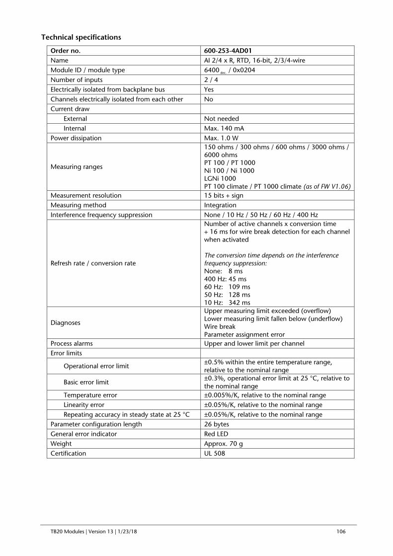
TB20 Modules | Version 13 | 1/23/18 106
Technical specifications
Order no. 600-253-4AD01 Name AI 2/4 x R, RTD, 16-bit, 2/3/4-wire Module ID / module type 6400 dec. / 0x0204 Number of inputs 2 / 4 Electrically isolated from backplane bus Yes Channels electrically isolated from each other No Current draw External Not needed Internal Max. 140 mA Power dissipation Max. 1.0 W
Measuring ranges
150 ohms / 300 ohms / 600 ohms / 3000 ohms / 6000 ohms PT 100 / PT 1000 Ni 100 / Ni 1000 LGNi 1000 PT 100 climate / PT 1000 climate (as of FW V1.06)
Measurement resolution 15 bits + sign Measuring method Integration Interference frequency suppression None / 10 Hz / 50 Hz / 60 Hz / 400 Hz
Refresh rate / conversion rate
Number of active channels x conversion time + 16 ms for wire break detection for each channel when activated The conversion time depends on the interference frequency suppression: None: 8 ms 400 Hz: 45 ms 60 Hz: 109 ms 50 Hz: 128 ms 10 Hz: 342 ms
Diagnoses
Upper measuring limit exceeded (overflow) Lower measuring limit fallen below (underflow) Wire break Parameter assignment error
Process alarms Upper and lower limit per channel Error limits
Operational error limit ±0.5% within the entire temperature range, relative to the nominal range
Basic error limit ±0.3%, operational error limit at 25 °C, relative to the nominal range
Temperature error ±0.005%/K, relative to the nominal range Linearity error ±0.05%/K, relative to the nominal range Repeating accuracy in steady state at 25 °C ±0.05%/K, relative to the nominal range Parameter configuration length 26 bytes General error indicator Red LED Weight Approx. 70 g Certification UL 508

TB20 Modules | Version 13 | 1/23/18 107
6.1.17. 600-254-4AB01, AI 2 x TC, 16-bit
Characteristics
• 2 inputs, electrically isolated from the backplane bus
• 2 process input words
• 2 process output words (for temperature compensation)
• Measuring range: ±80 mV
• Supported thermocouples: E, J, K, N, R, S, T, B, C, L
• Measurement resolution: up to 15 bits + sign
• External or internal temperature compensation
• Diagnostic messages
• Limit value alarms for each channel
• A bi-color LED (blue/red) indicates the module’s operating status and any malfunctions
Pin assignment
Input area (2 values, 4 bytes)
Value 1 Byte 0
Analog value for channel 0 Byte 1
Value 2 Byte 2
Analog value for channel 1 Byte 3
Output area (2 values, 4 bytes)
Value 1 Byte 0
External temperature compensation channel 0 Byte 1
Value 2 Byte 2
External temperature compensation channel 1 Byte 3
Parameters for the module
Diagnostic alarm: ON / OFF
Overflow / underflow diagnosis: ON / OFF
Representation values: Simatic S7 / Simatic S5 (for ±80 mV only)
Connection I/O 1 AI0 + 2 AI0 -
3 AI1 + 4 AI1 -
5 L+, 24 VDC 6 L+, 24 VDC
7 L-, GND 8 L-, GND
9 Mana 10 AUX

TB20 Modules | Version 13 | 1/23/18 108
Temperature unit: Celsius x 10 / Fahrenheit x 10 / Kelvin x 10
Parameters for each channel
Wire break detection: ON / OFF
Interference frequency suppression: None / 10 Hz / 50 Hz / 60 Hz / 400 Hz
Measuring ranges: ±80 mV
Thermocouples: E / J / K / N / R / S / T / B / C / L
Temperature compensation: internal / external / process data-based
Limit value alarms enabled: ON / OFF
Upper / lower limit: 16-bit analog value (±27648)
Technical specifications
Order no. 600-254-4AB01 Name AI 2 x TC, 16-bit Module ID / module type 7200 dec. / 0x0222 Number of inputs 2 Electrically isolated from backplane bus Yes Channels electrically isolated from each other No Current draw External Not needed Internal Max. 95 mA Power dissipation Max. 0.7 W Measuring ranges ±80 mV
Thermocouples
E (-270 °C … 990 °C) J (-210 °C ... 1200 °C) K (-270 °C … 1380 °C) N (-270 °C … 1320 °C) R (-50 °C … 1775 °C) S (-50 °C … 1775 °C) T (-270 °C … 405 °C) B (0 °C … 1800 °C) C (0 °C … 2320 °C) L (0 °C … 900 °C)
Resolution 15 bits + sign Measuring method Integration Interference frequency suppression None / 10 Hz / 50 Hz / 60 Hz / 400 Hz
Refresh rate / conversion rate
Number of active channels x conversion time + 16 ms for wire break detection for each channel when activated The conversion time will depend on the interference frequency suppression setting being used: None: 8 ms 400 Hz: 45 ms 60 Hz: 109 ms 50 Hz: 128 ms 10 Hz: 342 ms
Diagnoses Upper measuring limit exceeded (overflow) Lower measuring limit fallen below (underflow) Parameter assignment error
Process alarms Upper and lower limit per channel

TB20 Modules | Version 13 | 1/23/18 109
Error limits
Operational error limit ±0.5% within the entire temperature range, relative to the nominal range
Basic error limit ±0.3%, operational error limit at 25 °C, relative to the nominal range
Temperature error ±0.005%/K, relative to the nominal range Linearity error ±0.05%/K, relative to the nominal range Repeating accuracy in steady state at 25 °C ±0.05%/K, relative to the nominal range Parameter configuration length 26 bytes General error indicator Red LED Weight Approx. 70 g Certification UL 508

TB20 Modules | Version 13 | 1/23/18 110
6.1.18. 600-254-4AD01, AI 4 x TC, 16-bit
Characteristics
• 4 inputs, electrically isolated from the backplane bus
• 4 process input words
• 4 process output words (for temperature compensation)
• Measuring range: ±80 mV
• Supported thermocouples: E, J, K, N, R, S, T, B, C, L
• Measurement resolution: up to 15 bits + sign
• External or internal temperature compensation
• Diagnostic messages
• Limit value alarms for each channel
• A bi-color LED (blue/red) indicates the module’s operating status and any malfunctions
Pin assignment
Input area (4 values, 8 bytes)
Value 1 Byte 0
Analog value for channel 0 Byte 1
Value 2 Byte 2
Analog value for channel 1 Byte 3
Value 3 Byte 4
Analog value for channel 2 Byte 5
Value 4 Byte 6
Analog value for channel 3 Byte 7
Output area (4 values, 8 bytes)
Value 1 Byte 0
External temperature compensation channel 0 Byte 1
Value 2 Byte 2
External temperature compensation channel 1 Byte 3
Value 3 Byte 4
External temperature compensation channel 2 Byte 5
Value 4 Byte 6
External temperature compensation channel 3 Byte 7
Connection I/O 1 AI0 + 2 AI0 -
3 AI1 + 4 AI1 -
5 AI2 + 6 AI2 -
7 AI3 + 8 AI3 -
9 Mana 10 AUX

TB20 Modules | Version 13 | 1/23/18 111
Parameters for the module
Diagnostic alarm: ON / OFF
Overflow / underflow diagnosis: ON / OFF
Representation values: Simatic S7 / Simatic S5 (for ±80 mV only)
Temperature unit: Celsius x 10 / Fahrenheit x 10 / Kelvin x 10
Parameters for each channel
Wire break detection: ON / OFF
Interference frequency suppression: None / 10 Hz / 50 Hz / 60 Hz / 400 Hz
Measuring ranges: ±80 mV
Thermocouples: E / J / K / N / R / S / T / B / C / L
Temperature compensation: internal / external / process data-based
Limit value alarms enabled: ON / OFF
Upper / lower limit: 16-bit analog value (±27648)
Technical specifications
Order no. 600-254-4AD01 Name AI 4 x TC, 16-bit Module ID / module type 7400 dec. / 0x0244 Number of inputs 4 Electrically isolated from backplane bus Yes Channels electrically isolated from each other No Current draw External Not needed Internal Max. 95 mA Power dissipation Max. 0.7 W Measuring ranges ±80mV
Thermocouples
E (-270 °C … 990 °C) J (-210 °C ... 1200 °C) K (-270 °C … 1380 °C) N (-270 °C … 1320 °C) R (-50 °C … 1775 °C) S (-50 °C … 1775 °C) T (-270 °C … 405 °C) B (0 °C … 1800 °C) C (0 °C … 2320 °C) L (0 °C … 900 °C)
Resolution 15 bits + sign Measuring method Integration Interference frequency suppression None / 10 Hz / 50 Hz / 60 Hz / 400 Hz
Refresh rate / conversion rate
Number of active channels x conversion time + 16 ms for wire break detection for each channel when activated The conversion time will depend on the interference frequency suppression setting being used: None: 8 ms 400 Hz: 45 ms 60 Hz: 109 ms 50 Hz: 128 ms 10 Hz: 342 ms
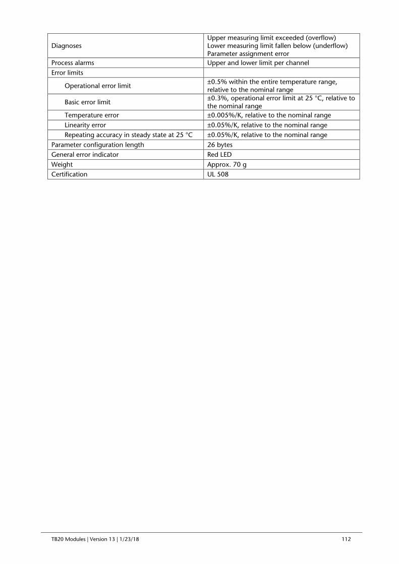
TB20 Modules | Version 13 | 1/23/18 112
Diagnoses Upper measuring limit exceeded (overflow) Lower measuring limit fallen below (underflow) Parameter assignment error
Process alarms Upper and lower limit per channel Error limits
Operational error limit ±0.5% within the entire temperature range, relative to the nominal range
Basic error limit ±0.3%, operational error limit at 25 °C, relative to the nominal range
Temperature error ±0.005%/K, relative to the nominal range Linearity error ±0.05%/K, relative to the nominal range Repeating accuracy in steady state at 25 °C ±0.05%/K, relative to the nominal range Parameter configuration length 26 bytes General error indicator Red LED Weight Approx. 70 g Certification UL 508

TB20 Modules | Version 13 | 1/23/18 113
6.1.19. 600-254-4AB02, AI 2 x TC, Iso., 16-bit
Characteristics
• 2 inputs
• Channels electrically isolated from each other and from the backplane bus
• 2 process input words, 2 process output words (for temperature compensation)
• Measuring range: ±80 mV
• Supported thermocouples: E, J, K, N, R, S, T, B, C, L
• Measurement resolution: 15 bits + sign
• External or internal temperature compensation
• Red/green bi-color LEDs (one for each channel) indicate the channels’ states
• Wire break detection
• Diagnostic messages
• Limit value alarms for each channel
• A bi-color LED (blue/red) indicates the module’s operating status and any malfunctions
Pin assignment
Channel LED signals:
Flashing red light = Parameter assignment error on channel
Solid red light = Reading overflow/underflow or wire break
Flashing green light = Reading within overdrive range
Solid green light = Channel configured, normal reading
Off = Channel disabled or module not yet configured
Connection I/O 1 AI0 + 2 AI0 -
3 AI1 + 4 AI1 -
5 n.c. 6 n.c.
7 n.c. 8 n.c.
9 n.c. 10 AUX

TB20 Modules | Version 13 | 1/23/18 114
Input area (2 values, 4 bytes)
Value 1 Byte 0
Analog value for channel 0 Byte 1
Value 2 Byte 2
Analog value for channel 1 Byte 3
Output area (2 values, 4 bytes)
Value 1 Byte 0
External temperature compensation channel 0 Byte 1
Value 2 Byte 2
External temperature compensation channel 1 Byte 3
Parameters for the module
Diagnostic alarm: ON / OFF
Overflow / underflow diagnosis: ON / OFF
Representation values: Simatic S7 / Simatic S5 (for ±80 mV only)
Temperature unit: Celsius x 10 / Fahrenheit x 10 / Kelvin x 10
Parameters for each channel
Wire break detection: ON / OFF
Interference frequency suppression: None / 10 Hz / 50 Hz / 60 Hz / 400 Hz
Measuring ranges: ±80 mV
Thermocouples: E / J / K / N / R / S / T / B / C / L
Temperature compensation: internal / external / process data-based
Limit value alarms enabled: ON / OFF
Upper / lower limit: 16-bit analog value (±27648)
Technical specifications
Order no. 600-254-4AB02 Name AI 2 x TC, Iso., 16-bit Module ID / module type 7201 dec. / 0x0222 Number of inputs 2 Electrically isolated from backplane bus Yes Channels electrically isolated from each other Yes Current draw External Not needed Internal Max. 140 mA Power dissipation Max. 1 W Measuring ranges ±80 mV
Thermocouples
E (-270 °C … 990 °C) J (-210 °C ... 1200 °C) K (-270 °C … 1380 °C) N (-270 °C … 1320 °C) R (-50 °C … 1775 °C) S (-50 °C … 1775 °C) T (-270 °C … 405 °C) B (0 °C … 1800 °C) C (0 °C … 2320 °C) L (0 °C … 900 °C)

TB20 Modules | Version 13 | 1/23/18 115
Measurement resolution 15 bits + sign Measuring method Integration Interference frequency suppression None / 10 Hz / 50 Hz / 60 Hz / 400 Hz
Refresh rate / conversion rate
Depends on the interference frequency suppression setting being used: None: 2 ms 400 Hz: 8 ms 60 Hz: 51 ms 50 Hz: 60 ms 10 Hz: 160 ms
Diagnoses
Upper measuring limit exceeded (overflow) Lower measuring limit fallen below (underflow) Wire break Parameter assignment error
Process alarms Upper and lower limit per channel Error limits
Operational error limit ±0.5% within the entire temperature range, relative to the nominal range
Basic error limit ±0.3%, operational error limit at 25 °C, relative to the nominal range
Temperature error ±0.005%/K, relative to the nominal range Linearity error ±0.05%/K, relative to the nominal range Repeating accuracy in steady state at 25 °C ±0.05%/K, relative to the nominal range Parameter configuration length 26 bytes General error indicator Red LED Weight Approx. 70 g Certification UL 508

TB20 Modules | Version 13 | 1/23/18 116
6.1.20. 600-254-4AD02, AI 4 x TC, Iso., 16-bit
Characteristics
• 4 inputs
• Channels electrically isolated from each other and from the backplane bus
• 4 process input words, 4 process output words (for temperature compensation)
• Measuring range: ±80 mV
• Supported thermocouples: E, J, K, N, R, S, T, B, C, L
• Measurement resolution: 15 bits + sign
• External or internal temperature compensation
• Red/green bi-color LEDs (one for each channel) indicate the channels’ states
• Wire break detection
• Diagnostic messages
• Limit value alarms for each channel
• A bi-color LED (blue/red) indicates the module’s operating status and any malfunctions
Pin assignment
Channel LED signals:
Flashing red light = Parameter assignment error on channel
Solid red light = Reading overflow/underflow or wire break
Flashing green light = Reading within overdrive range
Solid green light = Channel configured, normal reading
Off = Channel disabled or module not yet configured
Connection I/O 1 AI0 + 2 AI0 -
3 AI1 + 4 AI1 -
5 AI2 + 6 AI2 -
7 AI3 + 8 AI3 -
9 n.c. 10 AUX

TB20 Modules | Version 13 | 1/23/18 117
Input area (4 values, 8 bytes)
Value 1 Byte 0
Analog value for channel 0 Byte 1
Value 2 Byte 2
Analog value for channel 1 Byte 3
Value 3 Byte 4
Analog value for channel 2 Byte 5
Value 4 Byte 6
Analog value for channel 3 Byte 7
Output area (4 values, 8 bytes)
Value 1 Byte 0
External temperature compensation channel 0 Byte 1
Value 2 Byte 2
External temperature compensation channel 1 Byte 3
Value 3 Byte 4
External temperature compensation channel 2 Byte 5
Value 4 Byte 6
External temperature compensation channel 3 Byte 7
Parameters for the module
Diagnostic alarm: ON / OFF
Overflow / underflow diagnosis: ON / OFF
Representation values: Simatic S7 / Simatic S5 (for ±80 mV only)
Temperature unit: Celsius x 10 / Fahrenheit x 10 / Kelvin x 10
Parameters for each channel
Wire break detection: ON / OFF
Interference frequency suppression: None / 10 Hz / 50 Hz / 60 Hz / 400 Hz
Measuring ranges: ±80 mV
Thermocouples: E / J / K / N / R / S / T / B / C / L
Temperature compensation: internal / external / process data-based
Limit value alarms enabled: ON / OFF
Upper / lower limit: 16-bit analog value (±27648)
Technical specifications
Order no. 600-254-4AD02 Name AI 4 x TC, Iso., 16-bit Module ID / module type 7401 dec. / 0x0244 Number of inputs 4 Electrically isolated from backplane bus Yes Channels electrically isolated from each other Yes Current draw External Not needed Internal Max. 95 mA Power dissipation Max. 0.7 W Measuring ranges ±80mV

TB20 Modules | Version 13 | 1/23/18 118
Thermocouples
E (-270 °C … 990 °C) J (-210 °C ... 1200 °C) K (-270 °C … 1380 °C) N (-270 °C … 1320 °C) R (-50 °C … 1775 °C) S (-50 °C … 1775 °C) T (-270 °C … 405 °C) B (0 °C … 1800 °C) C (0 °C … 2320 °C) L (0 °C … 900 °C)
Measurement resolution 15 bits + sign Measuring method Integration Interference frequency suppression None / 10 Hz / 50 Hz / 60 Hz / 400 Hz
Refresh rate / conversion rate
Depends on the interference frequency suppression setting being used: None: 2.5 ms 400 Hz: 8 ms 60 Hz: 51 ms 50 Hz: 60 ms 10 Hz: 160 ms
Diagnoses
Upper measuring limit exceeded (overflow) Lower measuring limit fallen below (underflow) Wire break Parameter assignment error
Process alarms Upper and lower limit per channel Error limits
Operational error limit ±0.5% within the entire temperature range, relative to the nominal range
Basic error limit ±0.3%, operational error limit at 25 °C, relative to the nominal range
Temperature error ±0.005%/K, relative to the nominal range Linearity error ±0.05%/K, relative to the nominal range Repeating accuracy in steady state at 25 °C ±0.05%/K, relative to the nominal range Parameter configuration length 26 bytes General error indicator Red LED Weight Approx. 70 g Certification UL 508

TB20 Modules | Version 13 | 1/23/18 119
6.1.21. 600-254-4AH22, AI 8 x TC, Iso., 16-bit
Characteristics
• 8 inputs
• Channels electrically isolated from each other and from the backplane bus
• 8 process input words, 8 process output words (for temperature compensation)
• Measuring range: ±80 mV
• Supported thermocouples: E, J, K, N, R, S, T, B, C, L
• Measurement resolution: 15 bits + sign
• External or internal temperature compensation
• Red/green bi-color LEDs (one for each channel) indicate the channels’ states
• Wire break detection
• Diagnostic messages
• Limit value alarms for each channel
• A bi-color LED (blue/red) indicates the module’s operating status and any malfunctions
Pin assignment
Channel LED signals:
Flashing red light = Parameter assignment error on channel
Solid red light = Reading overflow/underflow or wire break
Flashing green light = Reading within overdrive range
Solid green light = Channel configured, normal reading
Off = Channel disabled or module not yet configured
Connection I/O Connection I/O 1 AI0 + 11 AI4 + 2 AI0 - 12 AI4 - 3 AI1 + 13 AI5 + 4 AI1 - 14 AI5 - 5 AI2 + 15 AI6 + 6 AI2 - 16 AI6 - 7 AI3 + 17 AI7 + 8 AI3 - 18 AI7 - 9 n.c. 19 n.c. 10 AUX 20 AUX

TB20 Modules | Version 13 | 1/23/18 120
Input area (16 bytes)
Value 1 Byte 0
Analog value for channel 0 Byte 1
Value 2 Byte 2
Analog value for channel 1 Byte 3
Value 3 Byte 4
Analog value for channel 2 Byte 5
Value 4 Byte 6
Analog value for channel 3 Byte 7
Value 5 Byte 8
Analog value for channel 4 Byte 9
Value 6 Byte 10
Analog value for channel 5 Byte 11
Value 7 Byte 12
Analog value for channel 6 Byte 13
Value 8 Byte 14
Analog value for channel 7 Byte 15
Output area (16 byte)
Value 1 Byte 0
External temperature compensation channel 0 Byte 1
Value 2 Byte 2
External temperature compensation channel 1 Byte 3
Value 3 Byte 4
External temperature compensation channel 2 Byte 5
Value 4 Byte 6
External temperature compensation channel 3 Byte 7
Value 5 Byte 8
External temperature compensation channel 4 Byte 9
Value 6 Byte 10
External temperature compensation channel 5 Byte 11
Value 7 Byte 12
External temperature compensation channel 6 Byte 13
Value 8 Byte 14
External temperature compensation channel 7 Byte 15
Parameters for the module
Diagnostic alarm: ON / OFF
Overflow / underflow diagnosis: ON / OFF
Representation values: Simatic S7 / Simatic S5 (for ±80 mV only)
Temperature unit: Celsius x 10 / Fahrenheit x 10 / Kelvin x 10
Parameters for each channel
Wire break detection: ON / OFF
Interference frequency suppression: None / 10 Hz / 50 Hz / 60 Hz / 400 Hz
Measuring ranges: ±80 mV
Thermocouples: E / J / K / N / R / S / T / B / C / L
Temperature compensation: internal / external / process data-based
Limit value alarms enabled: ON / OFF
Upper / lower limit: 16-bit analog value (±27648)

TB20 Modules | Version 13 | 1/23/18 121
Technical specifications
Order no. 600-254-4AH22 Name AI 8 x TC, Iso., 16-bit Module ID / module type 7800 dec. / 0x0288 Number of inputs 8 Electrically isolated from backplane bus Yes Channels electrically isolated from each other Yes Current draw External Not needed Internal Max. 140 mA Power dissipation Max. 1 W Measuring ranges ±80mV
Thermocouples
E (-270 °C … 990 °C) J (-210 °C ... 1200 °C) K (-270 °C … 1380 °C) N (-270 °C … 1320 °C) R (-50 °C … 1775 °C) S (-50 °C … 1775 °C) T (-270 °C … 405 °C) B (0 °C … 1800 °C) C (0 °C … 2320 °C) L (0 °C … 900 °C)
Measurement resolution 15 bits + sign Measuring method Integration Interference frequency suppression None / 10 Hz / 50 Hz / 60 Hz / 400 Hz
Refresh rate / conversion rate
Depends on the interference frequency suppression setting being used: None: 3 ms 400 Hz: 8 ms 60 Hz: 51 ms 50 Hz: 60 ms 10 Hz: 160 ms
Diagnoses
Upper measuring limit exceeded (overflow) Lower measuring limit fallen below (underflow) Wire break Parameter assignment error
Process alarms Upper and lower limit per channel Error limits
Operational error limit ±0.5% within the entire temperature range, relative to the nominal range
Basic error limit ±0.3%, operational error limit at 25 °C, relative to the nominal range
Temperature error ±0.005%/K, relative to the nominal range Linearity error ±0.05%/K, relative to the nominal range Repeating accuracy in steady state at 25 °C ±0.05%/K, relative to the nominal range Parameter configuration length 51 bytes General error indicator Red LED Weight Approx. 110 g Certification UL 508

TB20 Modules | Version 13 | 1/23/18 122
6.2. Analog Output Modules
6.2.1. 600-260-4AB01, AO 2 x I, 0/4–20 mA, 12-bit
Characteristics
• 2 analog outputs (electrically isolated from the backplane bus)
• 2 process output words (4 bytes)
• Output range 0 ... 20 mA, 4 ... 20 mA
• Resolution of up to 12 bits + sign
• Substitute value functionality
• Diagnostic messages
• A bi-color LED (blue/red) indicates the module’s operating status and any malfunctions
Pin assignment
Parameters for the module
Diagnostic alarm: ON / OFF
Format of values: Simatic S7 / Simatic S5 / INT16
Parameters for each channel
Wire break detection: ON / OFF
Output ranges: 0 ... 20 mA / 4 ... 20 mA
Available substitute value options: Outputs de-energized / Retain last value / Apply substitute value
Substitute value: 16-bit analog value (±27648)
Connection I/O 1 AO0 + 2 AO0 - 3 AO1 + 4 AO1 - 5 Mana 6 L+, 24 VDC 7 L+, 24 VDC 8 L-, GND 9 L-, GND 10 AUX

TB20 Modules | Version 13 | 1/23/18 123
Technical specifications
Order no. 600-260-4AB01 Name AO 2 x I, 0/4–20 mA, 12-bit Module ID / module type 8200 dec. / 0x0220 Number of outputs 2
Output ranges 0 ... 20 mA 4 ... 20 mA
Electrically isolated from backplane bus Yes Channels electrically isolated from each other No Current draw External Max. 60 mA Internal Max. 26 mA Power dissipation Max. 1.9 W Connection for actuators 2-wire connection Load resistance Max. 600 ohms Inductive load Max. 100 mH No-load voltage Max. 18 V Resolution 12 bits Refresh time 0.2 ms
Settling time
0.2 ms for resistive loads 2.2 ms for capacitive loads 0.5 ms for inductive loads (<=1 mH) 3.3 ms for inductive loads (<=3.3 mH)
Diagnoses No external reference voltage (L+) Wire break Parameter assignment error
Error limits
Operational error limit ±0.5% within the entire temperature range, relative to the nominal range
Basic error limit ±0.3%, operational error limit at 25 °C, relative to the nominal range
Temperature error ±0.005%/K, relative to the nominal range Linearity error ±0.05%/K, relative to the nominal range Repeating accuracy in steady state at 25 °C ±0.05%/K, relative to the nominal range Parameter configuration length 7 bytes General error indicator Red LED Weight Approx. 70 g Certification UL 508

TB20 Modules | Version 13 | 1/23/18 124
6.2.2. 600-260-4AD01, AO 4 x I, 0/4-20 mA, 12-bit
Characteristics
• 4 analog outputs (electrically isolated from the backplane bus)
• 4 process output words (8 bytes)
• Output range 0 ... 20 mA, 4 ... 20 mA
• Resolution of up to 12 bits
• Substitute value functionality
• Diagnostic messages
• A bi-color LED (blue/red) indicates the module’s operating status and any malfunctions
Pin assignment
Parameters for the module
Diagnostic alarm: ON / OFF
Format of values: Simatic S7 / Simatic S5 / INT16
Parameters for each channel
Wire break detection: ON / OFF
Output range 0 ... 20 mA, 4 ... 20 mA
Available substitute value options: Outputs de-energized / Retain last value / Apply substitute value
Substitute value: 16-bit analog value (±27648)
Connection I/O 1 AO0 + 2 AO0 - 3 AO1 + 4 AO1 - 5 AO2 + 6 AO2 - 7 AO3 + 8 AO3 - 9 GND 10 AUX

TB20 Modules | Version 13 | 1/23/18 125
Technical specifications
Order no. 600-260-4AD01 Name AO 4 x I, 0/4–20 mA, 12-bit Module ID / module type 8400 dec. / 0x0240 Number of outputs 4
Output ranges 0 ... 20 mA 4 ... 20 mA
Electrically isolated from backplane bus Yes Channels electrically isolated from each other No Current draw External Max. 100 mA Internal Max. 26 mA Power dissipation Max. 3 W Connection for actuators 2-wire connection Load resistance Max. 600 ohms Inductive load Max. 100 mH No-load voltage Max. 18 V Resolution 12 bits Refresh time 0.2 ms
Settling time
0.2 ms for resistive loads 2.2 ms for capacitive loads 0.5 ms for inductive loads (<=1 mH) 3.3 ms for inductive loads (<=3.3 mH)
Diagnoses No external reference voltage (L+) Wire break Parameter assignment error
Error limits
Operational error limit ±0.5% within the entire temperature range, relative to the nominal range
Basic error limit ±0.3%, operational error limit at 25 °C, relative to the nominal range
Temperature error ±0.005%/K, relative to the nominal range Linearity error ±0.05%/K, relative to the nominal range Repeating accuracy in steady state at 25 °C ±0.05%/K, relative to the nominal range Parameter configuration length 13 bytes General error indicator Red LED Weight Approx. 70 g Certification UL 508

TB20 Modules | Version 13 | 1/23/18 126
6.2.3. 600-261-4AB01, AO 2 x U, ±10 V, 0–10 V, 1–5 V, 12-bit
Characteristics
• 2 analog outputs (electrically isolated from the backplane bus)
• 2 process output words (4 bytes)
• Output ranges: ±10 V, 0–10 V, 1–5 V
• Resolution of up to 12 bits + sign
• Substitute value functionality
• Diagnostic messages
• A bi-color LED (blue/red) indicates the module’s operating status and any malfunctions
Pin assignment
Parameters for the module
Diagnostic alarm: ON / OFF
Format of values: Simatic S7 / Simatic S5 / INT16
Parameters for each channel
Wire break detection: ON / OFF
Output ranges: ±10 V, 0–10 V, 1–5 V
Available substitute value options: Outputs de-energized / Retain last value / Apply substitute value
Substitute value: 16-bit analog value (±27648)
Connection I/O 1 AO0 + 2 AO0 - 3 AO1 + 4 AO1 - 5 Mana 6 L+, 24 VDC 7 L+, 24 VDC 8 L-, GND 9 L-, GND 10 AUX

TB20 Modules | Version 13 | 1/23/18 127
Technical specifications
Order no. 600-261-4AB01 Name AO 2 x U, ±10 V, 0–10 V, 1–5 V, 12-bit Module ID / module type 9200 dec. / 0x0220 Number of outputs 2
Output ranges ±10 V 0–10 V 1–5 V
Electrically isolated from backplane bus Yes Channels electrically isolated from each other No Current draw External Max. 45 mA Internal Max. 24 mA Power dissipation Max. 1.6 W Connection for actuators 2-wire connection Load resistance Min. 1 kohm Capacitive load Max. 1 µF Short-circuit protection Yes Short-circuit current Max. 25 mA Resolution 12 bits + sign Refresh time 0.2 ms
Settling time
0.2 ms for resistive loads 2.2 ms for capacitive loads 0.5 ms for inductive loads (<=1 mH) 3.3 ms for inductive loads (<=3.3 mH)
Diagnoses No external reference voltage (L+) Configuration error
Error limits
Operational error limit ±0.5% within the entire temperature range, relative to the nominal range
Basic error limit ±0.3%, operational error limit at 25 °C, relative to the nominal range
Temperature error ±0.005%/K, relative to the nominal range Linearity error ±0.05%/K, relative to the nominal range Repeating accuracy in steady state at 25 °C ±0.05%/K, relative to the nominal range Parameter configuration length 7 bytes General error indicator Red LED Weight Approx. 70 g Certification UL 508
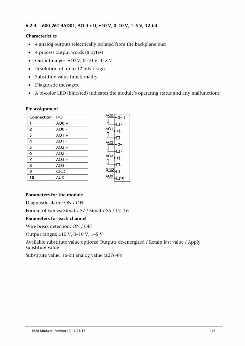
TB20 Modules | Version 13 | 1/23/18 128
6.2.4. 600-261-4AD01, AO 4 x U,.±10 V, 0–10 V, 1–5 V, 12-bit
Characteristics
• 4 analog outputs (electrically isolated from the backplane bus)
• 4 process output words (8 bytes)
• Output ranges: ±10 V, 0–10 V, 1–5 V
• Resolution of up to 12 bits + sign
• Substitute value functionality
• Diagnostic messages
• A bi-color LED (blue/red) indicates the module’s operating status and any malfunctions
Pin assignment
Parameters for the module
Diagnostic alarm: ON / OFF
Format of values: Simatic S7 / Simatic S5 / INT16
Parameters for each channel
Wire break detection: ON / OFF
Output ranges: ±10 V, 0–10 V, 1–5 V
Available substitute value options: Outputs de-energized / Retain last value / Apply substitute value
Substitute value: 16-bit analog value (±27648)
Connection I/O 1 AO0 + 2 AO0 - 3 AO1 + 4 AO1 - 5 AO2 + 6 AO2 - 7 AO3 + 8 AO3 - 9 GND 10 AUX

TB20 Modules | Version 13 | 1/23/18 129
Technical specifications
Order no. 600-261-4AD01 Name AO 4 x U, ±10 V, 0–10 V, 1–5 V, 12-bit Module ID / module type 9400 dec. / 0x0240 Number of outputs 4
Output ranges ±10 V 0–10 V 1–5 V
Electrically isolated from backplane bus Yes Channels electrically isolated from each other No Current draw External Max. 75 mA Internal Max. 24 mA Power dissipation Max. 2.4 W Connection for actuators 2-wire connection Load resistance Min. 1 kohm Capacitive load Max. 1 µF Short-circuit protection Yes Short-circuit current Max. 25 mA Resolution 12 bits + sign Refresh time 0.2 ms
Settling time
0.2 ms for resistive loads 2.2 ms for capacitive loads 0.5 ms for inductive loads (<=1 mH) 3.3 ms for inductive loads (<=3.3 mH)
Diagnoses No external reference voltage (L+) Configuration error
Error limits
Operational error limit ±0.5% within the entire temperature range, relative to the nominal range
Basic error limit ±0.3%, operational error limit at 25 °C, relative to the nominal range
Temperature error ±0.005%/K, relative to the nominal range Linearity error ±0.05%/K, relative to the nominal range Repeating accuracy in steady state at 25 °C ±0.05%/K, relative to the nominal range Parameter configuration length 13 bytes General error indicator Red LED Weight Approx. 70 g Certification UL 508

TB20 Modules | Version 13 | 1/23/18 130
6.3. Basic Analog Value Representation Principles
6.3.1. General Information
CPUs are only able to process analog values as binary values. Analog input modules convert analog input values into binary numbers with a resolution of 16 bits.
6.3.2. Analog Value Representation with 16-bit Resolution
Analog values are represented as two’s complement fixed-point numbers. Each analog value’s sign is always represented by bit 15, i.e., if bit 15 = 1, the value is negative.
Sign
High-Byte Low-Byte
Bit 15 14 13 12 11 10 9 8 7 6 5 4 3 2 1 0
Value of bit 215 214 213 212 211 210 29 28 27 26 25 24 23 22 21 20
6.3.3. Reading Resolution
In certain analog input modules, the analog values’ resolution may be lower than 15 bits. When the resolution is lower than 15 bits, the “x” bits are set to “0” starting from the bit with the lowest value.
Resolution in bits (+ sign)
Units Analog value
Decimal Hexadecimal High-Byte Low-Byte
10 32 20h Sign 0 0 0 0 0 0 0 0 0 1 x x x x x
11 16 10h Sign 0 0 0 0 0 0 0 0 0 0 1 x x x x
12 8 8h Sign 0 0 0 0 0 0 0 0 0 0 0 1 x x x
13 4 4h Sign 0 0 0 0 0 0 0 0 0 0 0 0 1 x x
14 2 2h Sign 0 0 0 0 0 0 0 0 0 0 0 0 0 1 x
15 1 1h Sign 0 0 0 0 0 0 0 0 0 0 0 0 0 0 1

TB20 Modules | Version 13 | 1/23/18 131
6.4. Analog Value Representation in SIMATIC S7 Format
6.4.1. Simatic S7 Analog Value Representation for Voltage Measuring Ranges
System Voltage measuring range Range
Dec. Hex. ±10 V ±5 V ±2.5 V ±80 mV
32767 7FFF Overflow
30720 7800
30719 77FF 11.111 V 5.555 V 2.778 V 88.88 mV Over-range
27649 6C01
27648 6C00 10.000 V 5.000 V 2.500 V 80 mV
Nominal range
20736 5100 7.500 V 3.75 V 1.875 V
1 1 361 µV 180 µV 90 µV 2.9 µV
0 0 0 V 0 V 0 V 0 mV
-1 FFFF -361 µV -180 µV -90 µV -2.9 µV
-20736 AF00 -7.500 V -3.750 V -1.875 V
-27648 9400 -10.000 V -5.000 V -2.500 V -80 mV
-27649 93FF Under-range
-30719 8801 -11.111 V -5.555 V -2.778 V -88.88 mV
-30720 8800 Underflow
-32768 8000
System Voltage measuring range Range
Dec. Hex. 1 to 5 V 0 to 10 V
32767 7FFF Overflow
30720 7800
30719 77FF 5.704 V 11.759 V Over-range
27649 6C01
27648 6C00 5 V 10 V
20736 5100 4 V 7.5 V
1 1 1 V + 144 µV 361 µV Nominal range
0 0 1 V 0 V
-1 FFFF 1 V + 144 µV
Negative values not allowed
Under-range -4864 ED00 296 mV
-4865 ECFF Underflow
-32768 8000
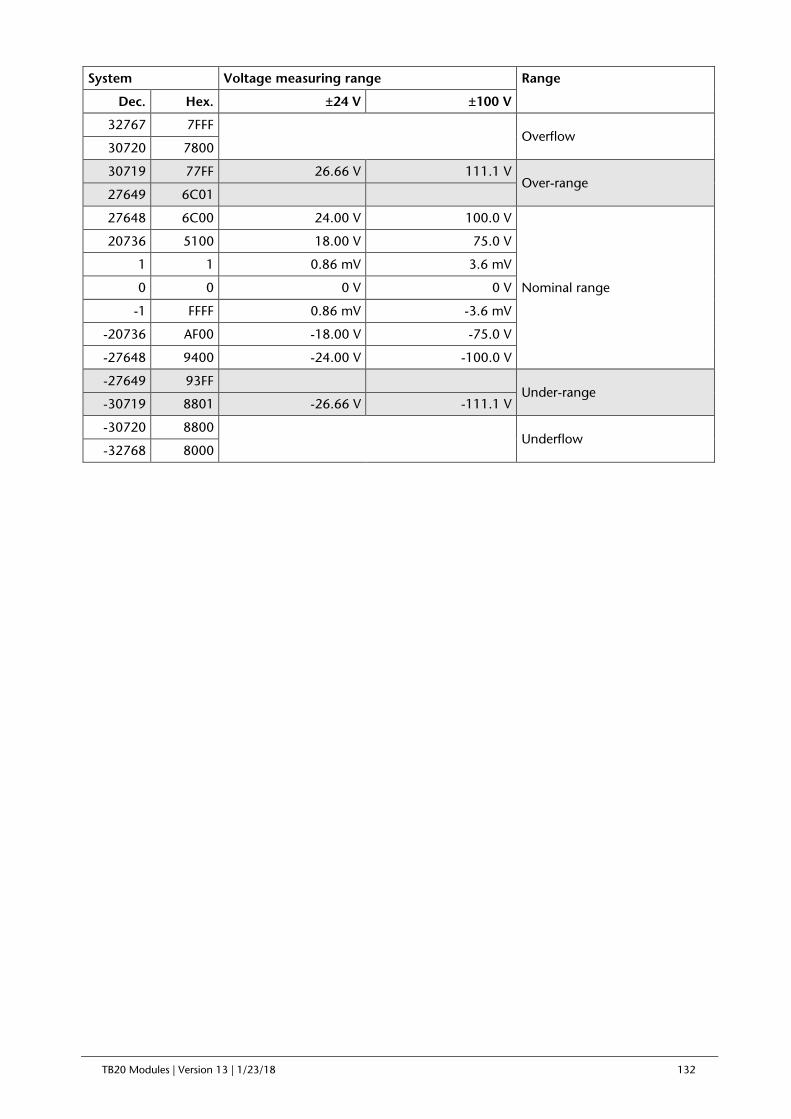
TB20 Modules | Version 13 | 1/23/18 132
System Voltage measuring range Range
Dec. Hex. ±24 V ±100 V
32767 7FFF Overflow
30720 7800
30719 77FF 26.66 V 111.1 V Over-range
27649 6C01
27648 6C00 24.00 V 100.0 V
Nominal range
20736 5100 18.00 V 75.0 V
1 1 0.86 mV 3.6 mV
0 0 0 V 0 V
-1 FFFF 0.86 mV -3.6 mV
-20736 AF00 -18.00 V -75.0 V
-27648 9400 -24.00 V -100.0 V
-27649 93FF Under-range
-30719 8801 -26.66 V -111.1 V
-30720 8800 Underflow
-32768 8000

TB20 Modules | Version 13 | 1/23/18 133
6.4.2. Simatic S7 Analog Value Representation for Current Measuring Ranges
System Current measuring range
Range
Dec. Hex. ±20 mA 0 ... 20 mA
32767 7FFF Overflow
30720 7800
30719 77FF 22.22 mA 22.22 mA Over-range
27649 6C01
27648 6C00 20 mA 20 mA
Nominal range
20736 5100 15 mA 15 mA
1 1 0.72 µA 0.72 µA
0 0 0 mA 0 mA
-1 FFFF -0.72 µA
Negative values not allowed
-4864 ED00 -3.52 mA
-20736 AF00 -15 mA
-27648 9400 -20 mA
-27649 93FF Under-range
-30719 8801 -22.22 mA
-30720 8800 Underflow
-32768 8000
System Current measuring range Range
Dec. Hex. 4–20 mA
32767 7FFF Overflow
30720 7800
30719 77FF 22.22 mA Over-range
27649 6C01
27648 6C00 20 mA
Nominal range 20736 5100 16 mA
1 1 4 mA + 0.58 µA
0 0 4 mA
-1 FFFF 4 mA – 0.58 µA Under-range
-4864 ED00 1.185 mA
-4865 AF00 Underflow
-32768 8000
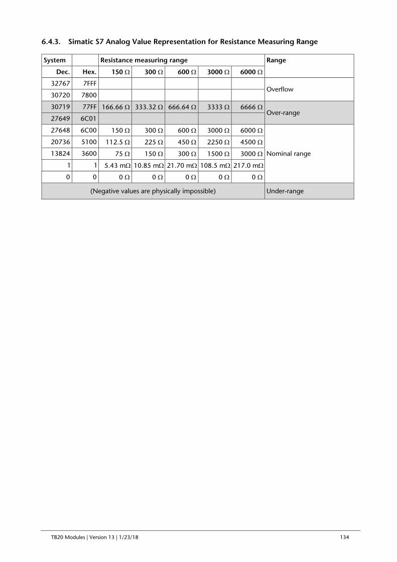
TB20 Modules | Version 13 | 1/23/18 134
6.4.3. Simatic S7 Analog Value Representation for Resistance Measuring Range
System Resistance measuring range Range
Dec. Hex. 150 Ω 300 Ω 600 Ω 3000 Ω 6000 Ω
32767 7FFF Overflow
30720 7800
30719 77FF 166.66 Ω 333.32 Ω 666.64 Ω 3333 Ω 6666 Ω Over-range
27649 6C01
27648 6C00 150 Ω 300 Ω 600 Ω 3000 Ω 6000 Ω
Nominal range
20736 5100 112.5 Ω 225 Ω 450 Ω 2250 Ω 4500 Ω
13824 3600 75 Ω 150 Ω 300 Ω 1500 Ω 3000 Ω
1 1 5.43 mΩ 10.85 mΩ 21.70 mΩ 108.5 mΩ 217.0 mΩ
0 0 0 Ω 0 Ω 0 Ω 0 Ω 0 Ω
(Negative values are physically impossible) Under-range

TB20 Modules | Version 13 | 1/23/18 135
6.4.4. Analog value representation for PT100/PT1000 Standard
Temperature in °C
Units Temperature in °F
Units Temperature in K
Units
Dec. Hex. Dec. Hex. Dec. Hex.
> 1000.0 32767 7FFF >1832.0 32767 7FFF >1273.2 32767 7FFF
1000.0 10000 2710 1832.0 18320 4790 1273.2 12732 31BC
850.1 8501 2135 1562.3 15623 3D07 1123.2 11232 2BE0
850.0 8500 2134 1562.2 15622 3D06 1123.1 11231 2BDF
1.0 10 000A 33.8 338 0152 274.2 2742 0AB6
0.1 1 0001 32.2 322 0142 273.3 2733 0AAD
0.0 0 0000 32.0 320 0140 273.2 2732 0AAC
-200.0 -2000 F830 -328.0 -3280 F330 73.2 732 02DC
-200.1 -2001 F82F -328.1 -3281 F32F 73.1 731 02DB
-240.0 -2400 F6A0 -400.0 -4000 F060 33.2 332 014C
< -240,0 -32768 8000 < -400,0 -32768 8000 < 33,2 -32768 8000
Note: The ranges with a gray background are overdrive or underdrive ranges
6.4.5. Analog value representation for Ni100/Ni1000/LGNi1000 Standard
Temperature in °C
Units Temperature in °F
Units Temperature in K
Units
Dec. Hex. Dec. Hex. Dec. Hex.
> 295.0 32767 7FFF > 563.1 32767 7FFF > 568.2 32767 7FFF
295.0 2950 0B86 563.0 5630 15FE 568.2 5682 1632
250.1 2501 09C5 482.1 4821 0F51 523.3 5233 1471
250.0 2500 09C4 482.0 4820 0F50 523.2 5232 1470
1.0 10 000A 33.8 338 0152 274.2 2742 0AB6
0.1 1 0001 32.2 322 0142 273.3 2733 0AAD
0.0 0 0000 32.0 320 0140 273.2 2732 0AAC
-60.0 -600 FDA8 -76.0 -760 FD08 213.2 2132 0854
-60.1 -601 FDA7 -76.1 -761 FD07 213.1 2131 0853
-110.0 -1100 FBB4 -166.0 -1660 F984 163.2 1632 0660
< -110,0 -32768 8000 < -166,0 -32768 8000 < 163,2 -32768 8000
Note: The ranges with a gray background are overdrive or underdrive ranges
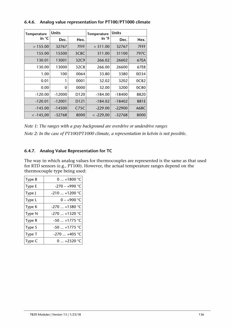
TB20 Modules | Version 13 | 1/23/18 136
6.4.6. Analog value representation for PT100/PT1000 climate
Temperature in °C
Units Temperature in °F
Units
Dec. Hex. Dec. Hex.
> 155.00 32767 7FFF > 311.00 32767 7FFF
155.00 15500 3C8C 311.00 31100 797C
130.01 13001 32C9 266.02 26602 67EA
130.00 13000 32C8 266.00 26600 67E8
1.00 100 0064 33.80 3380 0D34
0.01 1 0001 32.02 3202 0C82
0.00 0 0000 32.00 3200 0C80
-120.00 -12000 D120 -184.00 -18400 B820
-120.01 -12001 D121 -184.02 -18402 B81E
-145.00 -14500 C75C -229.00 -22900 A68C
< -145,00 -32768 8000 < -229,00 -32768 8000
Note 1: The ranges with a gray background are overdrive or underdrive ranges
Note 2: In the case of PT100/PT1000 climate, a representation in kelvin is not possible.
6.4.7. Analog Value Representation for TC
The way in which analog values for thermocouples are represented is the same as that used for RTD sensors (e.g., PT100). However, the actual temperature ranges depend on the thermocouple type being used:
Type B 0 ... +1800 °C
Type E -270 – +990 °C
Type J -210 ... +1200 °C
Type L 0 – +900 °C
Type K -270 ... +1380 °C
Type N -270 ... +1320 °C
Type R -50 ... +1775 °C
Type S -50 ... +1775 °C
Type T -270 ... +405 °C
Type C 0 ... +2320 °C

TB20 Modules | Version 13 | 1/23/18 137
6.5. Analog Value Representation in SIMATIC S5 Format
6.5.1. Simatic S5 Analog Value Representation for Voltage Measuring Ranges
System Voltage measuring range Range
Dec. Hex. ±10 V ±5 V ±2.5 V ±80 mV
32767 7FFF Overflow
18432 4800
18431 47FF 11.25 V 5.62 V 2.81 V 90 mV Over-range
16385 4001
16384 4000 10.000 V 5.000 V 2.500 V 80 mV
Nominal range
12288 3000 7.500 V 3.75 V 1.875 V
1 1 610 µV 305 µV 152 µV 4.8 µV
0 0 0 V 0 V 0 V 0 mV
-1 FFFF -610 µV -305 µV -152 µV - 4.8 µV
-12228 D000 -7.500 V -3.750 V -1.875 V
-16384 C000 -10.000 V -5.000 V -2.500 V -80 mV
-16385 BFFF Under-range
-18431 B801 -11.25 V -5.62 V -2.81 V -90 mV
-18432 B800 Underflow
-32768 8000
System Voltage measuring range Range
Dec. Hex. 1 to 5 V 0 to 10 V
32767 7FFF Overflow
30720 7800
30719 77FF 5.5 V 11.25 V Over-range
16385 4001
16384 4000 5 V 10 V
12288 3000 4 V 7.5 V
1 1 1 V + 244 µV 610 µV Nominal range
0 0 1 V 0 V
-1 FFFF 1 V + 244 µV
Negative values not allowed
Under-range -2048 F800 0.5 V
-2049 F7FF Underflow
-32768 8000

TB20 Modules | Version 13 | 1/23/18 138
6.5.2. Simatic S5 Analog Value Representation for Current Measuring Ranges
System Current measuring range
Range
Dec. Hex. ±20 mA 0 ... 20 mA
32767 7FFF Overflow
18432 4800
18431 47FF 22.5 mA 22.5 mA Over-range
16385 4001
16384 4000 20 mA 20 mA
Nominal range
12288 3000 15 mA 15 mA
1 1 1.22 µA 1.22 µA
0 0 0 mA 0 mA
-1 FFFF -1.22 µA
Negative values not allowed
-12228 D000 -15 mA
-16384 C000 -20 mA
-16385 BFFF Under-range
-18431 B801 -22.5 mA
-18432 B800 Underflow
-32768 8000
System Current measuring range Range
Dec. Hex. 4 ... 20 mA
32767 7FFF Overflow
30720 7800
30719 77FF 22.5 mA Over-range
16385 4001
16384 4000 20 mA
Nominal range 12288 3000 16 mA
1 1 4 mA + 0.98 µA
0 0 4 mA
-1 FFFF 4 mA – 0.98 µA Under-range
-2048 F800 1.185mA
-2049 F7FF Underflow
-32768 8000

TB20 Modules | Version 13 | 1/23/18 139
6.5.3. Simatic S5 Analog Value Representation for Resistance Measuring Range
System Resistance measuring range Range
Dec. Hex. 150 Ω 300 Ω 600 Ω 3000 Ω 6000 Ω
32767 7FFF Overflow
18432 4800
18431 47FF 168.74 Ω 337.48 Ω 674.96 Ω 3374 Ω 6749 Ω Over-range
16385 4001
16384 4000 150 Ω 300 Ω 600 Ω 3000 Ω 6000 Ω
Nominal range
12288 3000 112.5 Ω 225 Ω 450 Ω 2250 Ω 4500 Ω
8192 2000 75 Ω 150 Ω 300 Ω 1500 Ω 3000 Ω
1 1 9.16 mΩ 18.3 mΩ 27.3 mΩ 183 mΩ 366 mΩ
0 0 0 Ω 0 Ω 0 Ω 0 Ω 0 Ω
(Negative values are physically impossible) Under-range

TB20 Modules | Version 13 | 1/23/18 140
6.6. Analog Value Representation in INT16 Format
6.6.1. INT16 Analog Value Representation for Voltage Measuring Ranges
The value format INT16 knows no overflow or underflow. If the maximum PLC value is reached, this value also stops when the nominal range is exceeded.
System Voltage measuring range Range
Dec. Hex. ±10 V ±5 V ±2.5 V
32767 7FFF 10.000 V 5.000 V 2.500 V
Nominal range
24575 5FFF 7.500 V 3.75 V 1.875 V
1 1 305 µV 152 µV 76 µV
0 0 0 V 0 V 0 V
-1 FFFF -305 µV -152 µV -76 µV
-24575 A000 -7.500 V -3.750 V -1.875 V
-32768 8000 -10.000 V -5.000 V -2.500 V
System Voltage measuring range Range
Dec. Hex. 1 to 5 V 0 to 10 V
32767 7FFF 5 V 10 V
24575 5FFF 4 V 7.5 V
1 1 1 V + 122 µV 305 µV Nominal range
0 0 1 V 0 V
System Voltage measuring range Range
Dec. Hex. ±24 V ±100 V
32767 7FFF 24.00 V 100.0 V
Nominal range
24575 5FFF 18.00 V 75.0 V
1 1 0.73 mV 3.05 mV
0 0 0 V 0 V
-1 FFFF 0.73 mV -3.05 mV
-24575 A000 -18.00 V -75.0 V
-32768 8000 -24.00 V -100.0 V

TB20 Modules | Version 13 | 1/23/18 141
6.6.2. INT16 Analog Value Representation for Current Measuring Ranges
System Current measuring range
Range
Dec. Hex. ±20 mA 0 ... 20 mA
32767 7FFF 20 mA 20 mA
Nominal range
24575 5FFF 15 mA 15 mA
1 1 0.61 µA 0.61 µA
0 0 0 mA 0 mA
-1 FFFF -0.61 µA Negative values
not allowed -24575 A000 -15 mA
-32768 8000 -20 mA
System Current measuring range Range
Dec. Hex. 4–20 mA
32767 7FFF 20 mA
Nominal range 24575 5FFF 16 mA
1 1 4 mA + 0.48 µA
0 0 4 mA

TB20 Modules | Version 13 | 1/23/18 142
6.7. Definition of Operational Error Limit and Basic Error Limit
6.7.1. Operational error limit
“Operational error limit” is the analog input module’s error in measurement, within the entire permissible temperature range, relative to the module’s nominal range.
6.7.2. Basic error limit
“Basic error limit” is the operational error limit at 25 °C, relative to the module’s nominal range.
6.7.3. Example Showing How to Calculate the Input Error for an Analog Input Module
For this example, assume that a 600-252-4AD01 analog input module is being used with a “0 to 10 V” input range. The module will be operated at an ambient temperature of 30 °C. This is why the input error must be calculated on the basis of the operational error limit.
The relevant technical specifications indicate the following:
Operational error limit: ±0.5%
The input error for the module’s entire nominal range is:
±0.5% at 10 V = ±0.05 V
Input error ±0.05 V ±0.05 V ±0.05 V ±0.05 V ±0.05 V
Input value 1 V 2.5 V 5 V 8 V 10 V
Reading 0.95 ... 1.05 V 2.45 ... 2.55 V 4.95 ... 5.05 V 7.95 ... 8.05 V 9.95 ... 10.05 V
Relative error 5% 2% 1% 0.625% ±0.5%

TB20 Modules | Version 13 | 1/23/18 143
6.8. Connecting Sensors to Analog Inputs
6.8.1. Abbreviations Used
M+ Measuring line (positive)
M- Measuring line (negative)
MAna Reference potential of the analog circuit
L+ 24 VDC power supply terminal
GND Ground terminal
6.8.2. Signal Cables
Shielded twisted pair cables should be used for the analog signals. The analog cables’ shielding should be grounded at both ends of the cable.
Signal cables should not run parallel to power cables. In addition, signal and data cables must be routed in conduits or bundles separate from those for power cables. Make sure to route signal and data cables as close as possible to grounding surfaces, e.g., on stringers, metal rails, mounting plates, or the metal sheets making up a cabinet or enclosure.
Motor cables, power supply cables connected to the power grid, and IT cables must be routed with a distance of at least 0.2 m between each other within the equipment cabinet. If there are any crossings, there can be a smaller distance between them. Outside the equipment cabinet, motor cables must be routed in separate bundles at a distance of at least 0.3 m from other cables. This will reduce the amount of interference caused by induction.
If a joint is necessary, no more than 2 cm should be unshielded. The shielding on both cable ends must be connected with the shielding bus, not with a terminal. The cable’s shielding should not be connected to analog ground MAna.
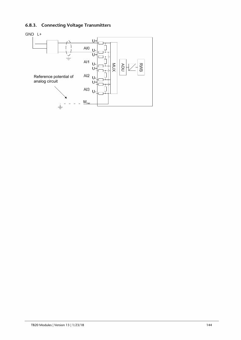
TB20 Modules | Version 13 | 1/23/18 144
6.8.3. Connecting Voltage Transmitters
Reference potential of analog circuit

TB20 Modules | Version 13 | 1/23/18 145
6.8.4. Connecting Current Transmitters
2-wire transducer:
4-wire transducer:
4-wire transmitters have a separate supply voltage.
Reference potential of analog circuit
Reference potential of analog circuit

TB20 Modules | Version 13 | 1/23/18 146
6.8.5. Connecting Resistance Thermometers and Resistors
Resistance thermometers and resistors are wired with a 4-wire, 3-wire, or 2-wire configuration.
When a 4-wire or 3-wire configuration is used, the module will deliver a constant current so that the voltage drop that occurs on the measuring lines will be compensated for. It is important for the connected constant current cables to be connected directly to the resistance thermometer/resistor! Measurements with 4-wire or 3-wire configuration provide more accurate results than measurements with 2-wire configuration.
2-wire measurement:
3-wire measurement:
4-wire measurement:

TB20 Modules | Version 13 | 1/23/18 147
6.8.6. Connecting Thermocouples
Reference potential of analog circuit

TB20 Modules | Version 13 | 1/23/18 148
6.9. Connecting Loads and Actuators to Analog Outputs
6.9.1. Abbreviations Used
U Analog voltage output
I+ Analog current output
MAna Reference potential of the analog circuit
L+ 24 VDC power supply terminal
GND Ground terminal
6.9.2. Connecting Loads/Actuators to Voltage Outputs
Reference potential of analog circuit

TB20 Modules | Version 13 | 1/23/18 149
6.9.3. Connecting Loads/Actuators to Current Outputs
Reference potential of analog circuit

TB20 Modules | Version 13 | 1/23/18 150
7. System Components
7.1. Power and isolation modules
7.1.1. 600-710-0AA01, 24 VDC, 8 A Power and Isolation Module
The 24 VDC, 8 A power and isolation module serves as a power supply module for the power bus’ 24 VDC, GND, and AUX to the right, while segmenting the power bus on the left. This module can be used to subdivide a power bus into individual segments.
Characteristics
• Powers the power bus to the right
• Segments the power bus on the left
• A green LED indicates the 24 VDC status
• A blue LED indicates the module's operating status
Pin assignment
Technical data
Order no. 600-710-0AA01 Name 24 VDC, 8 A power and isolation module Module ID / module type 30050 dec. / 0x1000 Load Per contact 8 A Total 24 VDC supply 8 A Total GND supply 8 A Total AUX supply 8 A Current draw External Max. 22 mA Internal Max. 5 mA Power dissipation Max. 0.3 W Electrically isolated from backplane bus Yes Weight Approx. 70 g Certification UL 508
The power and isolation module’s power supply must be externally fused with a fast-blow fuse appropriate for the required maximum current.
Connection I/O 1 L+, 24 VDC 2 L+, 24 VDC 3 L+, 24 VDC 4 L+, 24 VDC 5 GND 6 GND 7 GND 8 GND 9 AUX 10 AUX

TB20 Modules | Version 13 | 1/23/18 151
7.2. Potential Distributors
7.2.1. 600-730-4AD01, potential distributor 4 x DC 24 V, High Feature
The 4 x 24 VDC High Feature potential distributor can be used to power up to four transducers or 3-wire sensors. Moreover, it features a monitoring functionality that not only monitors the 24 V load voltage but also monitors for overload and short-circuit conditions at the supply outputs. In the event of a fault, the module will send a diagnostic signal to the PLC and change the color of the corresponding LEDs to red.
Characteristics
• 4 outputs, electrically isolated from the backplane bus
• 24 VDC output voltage
• 100 mA output voltage per channel
• A blue LED indicates the module's operating status
• Short-circuit protection with self-resetting fuse per channel
• Green/red LEDs indicate the outputs’ states
• 24 V load voltage monitoring and diagnosis
• Short circuit to GND monitoring and diagnosis for each individual channel
• 1 Byte channel status information in input image table
Pin assignment
Input area (1 Byte)
Bit 7 Bit 6 Bit 5 Bit 4 Bit 3 Bit 2 Bit 1 Bit 0
Byte 0 1= 24 V
Power supply off
0 0 0 Channel 3:
0=OK 1 = error
Channel 2: 0=OK
1 = error
Channel 1: 0=OK
1 = error
Channel 0: 0=OK
1 = error
Technical data
Order no. 600-730-4AD01 Name 4 x 24 VDC High Feature potential distributor Module ID / module type 31100 dec. / 0x3004 Number of outputs 4 Electrically isolated from backplane bus Yes Current draw
Connection I/O 1 MS0, DC 24 V 2 GND 3 MS1, DC 24 V 4 GND 5 MS2, DC 24 V 6 GND 7 MS3, DC 24 V 8 GND 9 L+, 24 VDC 10 AUX

TB20 Modules | Version 13 | 1/23/18 152
External 10 mA + load Internal Max. 30 mA Power dissipation Max. 0.1 W Load per output 100 mA Output short-circuit protection Fuse per channel, self-resetting Weight Approx. 70 g Certification UL 508
7.2.2. 600-720-0AH01, potential distributor 9 x DC 24 V
The 9 x 24 VDC potential distributor makes the 24 VDC supply from the power bus available on the front connector.
Characteristics
• Max. 8 A supply load
• Powers its outputs using the power bus
• A blue LED indicates the module's operating status
Pin assignment
Technical data
Order no. 600-720-0AH01 Name 9 x 24 VDC potential distributor Module ID / module type 31000 dec. / 0x3000 Number of outputs 9 Electrically isolated from backplane bus Yes Current draw External 0 mA Internal Max. 22 mA Power dissipation Max. 0.1 W Load Per contact 8 A Total load 8 A Weight Approx. 70 g Certification UL 508
Connection I/O 1 L+, 24 VDC 2 L+, 24 VDC 3 L+, 24 VDC 4 L+, 24 VDC 5 L+, 24 VDC 6 L+, 24 VDC 7 L+, 24 VDC 8 L+, 24 VDC 9 L+, 24 VDC 10 AUX

TB20 Modules | Version 13 | 1/23/18 153
7.2.3. 600-720-0BH01, 9 x GND Potential Distributor
The 9 x GND potential distributor makes the GND connection from the power bus available on the front connector.
Characteristics
• Max. 8 A supply load
• Powers its outputs using the power bus
• A blue LED indicates the module's operating status
Pin assignment
Technical data
Order no. 600-720-0BH01 Name 9 x GND potential distributor Module ID / module type 31010 dec. / 0x3000 Number of outputs 9 Electrically isolated from backplane bus Yes Current draw External 0 mA Internal Max. 22 mA Power dissipation Max. 0.1 W Load Per contact 8 A Total load 8 A Weight Approx. 70 g Certification UL 508
Connection I/O 1 GND 2 GND
3 GND 4 GND
5 GND 6 GND
7 GND 8 GND
9 GND 10 AUX

TB20 Modules | Version 13 | 1/23/18 154
7.2.4. 600-720-0CH01, 10 x AUX Potential Distributor
The 10 x AUX potential distributor makes the AUX connection from the power bus available on the front connector.
Characteristics
• Max. 8 A supply load
• Powers its outputs using the power bus
• A blue LED indicates the module's operating status
Pin assignment
Technical data
Order no. 600-720-0CH01 Name 10 x AUX potential distributor Module ID / module type 31020 dec. / 0x3000 Number of outputs 10 Electrically isolated from backplane bus Yes Current draw External 0 mA Internal Max. 22 mA Power dissipation Max. 0.1 W Load Per contact 8 A Total load 8 A Weight Approx. 70 g Certification UL 508
Connection I/O 1 AUX 2 AUX
3 AUX 4 AUX
5 AUX 6 AUX
7 AUX 8 AUX
9 AUX 10 AUX

TB20 Modules | Version 13 | 1/23/18 155
7.2.5. 600-720-0DH01, potential distributor 4 x DC 24 V + 4 x GND
The 4 x 24 VDC + 4 x GND potential distributor makes the 24 V supply and the GND connection from the power bus available on the front connector.
Characteristics
• Max. 8 A supply load
• Powers its outputs using the power bus
• A blue LED indicates the module's operating status
Pin assignment
Technical data
Order no. 600-720-0DH01 Name 4 x 24 VDC + 4 x GND potential distributor Module ID / module type 31030 dec. / 0x3000
Number of outputs 10 in three groups: 4 x 24 VDC, 4 x GND, 2 x AUX
Electrically isolated from backplane bus Yes Current draw External 0 mA Internal Max. 22 mA Power dissipation Max. 0.1 W Load Per contact 8 A Total load, 24 VDC 8 A Total load, GND 8 A Total load, AUX 8 A Weight Approx. 70 g Certification UL 508
Connection I/O 1 L+, 24 VDC 2 L+, 24 VDC
3 L+, 24 VDC 4 L+, 24 VDC
5 GND 6 GND
7 GND 8 GND
9 AUX 10 AUX

TB20 Modules | Version 13 | 1/23/18 156
7.2.6. 600-720-0XH01, 9 x Free Pot. distributor
The “9 x Free Pot.” distributor makes 9 contacts that are connected to each other available on the front connector. The potential distributed through these contacts can be freely chosen.
Characteristics
• Max. 8 A supply load
• Can accommodate any supply potential
• A blue LED indicates the module's operating status
Pin assignment
Technical data
Order no. 600-720-0XH01 Name 9 x free pot. potential distributor Module ID / module type 31040 dec. / 0x3000 Number of outputs 9 Electrically isolated from backplane bus Yes Current draw External 0 mA Internal Max. 22 mA Power dissipation Max. 0.1 W Load Per contact 8 A Total load 8 A Permissible potential difference relative to GND 48 VAC Weight Approx. 70 g Certification UL 508
Connection I/O 1 External pot. 2 External pot. 3 External pot. 4 External pot. 5 External pot. 6 External pot. 7 External pot. 8 External pot. 9 External pot. 10 AUX

TB20 Modules | Version 13 | 1/23/18 157
7.3. Power supply
7.3.1. 600-700-0AA01, 24 VDC Power Module
The 24 VDC power module provides a new supply voltage for the backplane bus and also serves as a power and isolation module for the power bus’ 24 VDC, GND, and AUX.
Characteristics
• New supply voltage for the backplane bus
• 2.5 A, 5 VDC output current for the backplane bus
• Powers the power bus to the right
• Segments the power bus on the left
• A green LED indicates the 24 VDC status
• Diagnostic messages in the event of a loss of voltage or short circuit on the backplane bus
• A bi-color LED (blue/red) indicates the module’s operating status and any malfunctions
Pin assignment
Parameters for the module
Diagnostic alarms: not enabled / enabled
Technical specifications
Order no. 600-700-0AA01 Name 24 VDC power module Module ID / module type 30000 dec. / 0x2000 Electrically isolated from backplane bus No Current draw External Max. 10 mA + load Internal Max. 35 mA 24 VDC supply 18–30 VDC Rated input current Max. 8 A, overcurrent protection device Reverse polarity protection Up to 60 V, electronic Power dissipation Max. 0.7 W
Connection I/O 1 24 VDC IN 2 GND IN 3 - 4 L+, 24 VDC 5 L+, 24 VDC 6 GND 7 GND 8 - 9 L+, 24 VDC 10 AUX

TB20 Modules | Version 13 | 1/23/18 158
Load Per contact 8 A Total load, 24 VDC 8 A Total load, GND 8 A Total load, AUX 8 A General error indicator Red LED Weight Approx. 70 g Certification UL 508
The power module’s power supply must be externally fused with a fast-blow fuse appropriate for the required maximum current.

TB20 Modules | Version 13 | 1/23/18 159
8. Configuring the Modules’ Parameters
8.1. General Information
All configurable modules come with a default parameter configuration. Depending on the bus system being used, the bus coupler will automatically load the desired operating parameter configuration into the modules when starting up or the user will have to transfer the configuration from the PLC by using the relevant methods.
When using bus couplers with project storage capabilities (e.g., CANopen couplers), the parameters can be configured in advance with the “TB20 ToolBox” software.
Modules can also be reconfigured at any time—even during operation. The methods that have to be used for this purpose will vary depending on the bus system and PLC being used.
The following section goes over the structure of the relevant parameter data sets. The corresponding default settings are underlined.
Note: All word and double word parameters are in big-endian format. Depending on the coupler used, these parameters are already correctly interpreted or need to be sent by the user in the correct order.
8.2. Digital Output Modules
8.2.1. 600-220-7AD01, DO 4 x DC 24 V, 700 mA, High Feature
Parameter set length: 6 bytes
Parameter Byte Bit 7 Bit 6 Bit 5 Bit 4 Bit 3 Bit 2 Bit 1 Bit 0
1 0 Diagnosis alarm - - - - -
2 1 Channel 3 behavior at CPU-
STOP Channel 2 behavior at CPU-
STOP Channel 1 behavior at CPU-
STOP Channel 0 behavior at CPU-
STOP 3 2 Pulse extension for channel 0 4 3 Pulse extension for channel 1 5 4 Pulse extension for channel 2
6 5 Pulse extension for channel 3
Diagnostic alarm: 1 = ON / 0 = OFF
Behavior at CPU-STOP 0 = Output Off / 1= Output On / 2 = Keep last value
Pulse extension: 0 = none / 1–255 = time (* 5ms)

TB20 Modules | Version 13 | 1/23/18 160
8.2.2. 600-220-7AH01, DO 8 x DC 24 V, 700 mA, High Feature
Parameter set length: 11 bytes
Para-meter Byte Bit 7 Bit 6 Bit 5 Bit 4 Bit 3 Bit 2 Bit 1 Bit 0
1 0 Diagnosis alarm - - - - -
2 1 Channel 3 behavior at
CPU-STOP Channel 2 behavior at
CPU-STOP Channel 1 behavior at
CPU-STOP Channel 0 behavior at
CPU-STOP
3 2 Channel 7 behavior at
CPU-STOP Channel 6 behavior at
CPU-STOP Channel 5 behavior at
CPU-STOP Channel 4 behavior at
CPU-STOP 4 3 Pulse extension for channel 0
5 4 Pulse extension for channel 1 6 5 Pulse extension for channel 2 7 6 Pulse extension for channel 3
8 7 Pulse extension for channel 4
9 8 Pulse extension for channel 5 10 9 Pulse extension for channel 6 11 10 Pulse extension for channel 7
Diagnostic alarm: 1 = ON / 0 = OFF
Behavior at CPU-STOP 0 = Output Off / 1= Output On / 2 = Keep last value
Pulse extension: 0 = none / 1–255 = time (* 5ms)
8.2.3. 600-220-7AP21, DO 16 x DC 24 V, 700 mA, High Feature
Parameter set length: 21 bytes
Para-meter Byte Bit 7 Bit 6 Bit 5 Bit 4 Bit 3 Bit 2 Bit 1 Bit 0
1 0 Diagnosis
alarm - - - - -
2 1 Channel 3 behavior at
CPU-STOP Channel 2 behavior at
CPU-STOP Channel 1 behavior at
CPU-STOP Channel 0 behavior at
CPU-STOP
3 2 Channel 7 behavior at
CPU-STOP Channel 6 behavior at
CPU-STOP Channel 5 behavior at
CPU-STOP Channel 4 behavior at
CPU-STOP
4 3 Channel 11 behavior at CPU-STOP
Channel 10 behavior at CPU-STOP
Channel 9 behavior at CPU-STOP
Channel 8 behavior at CPU-STOP
5 4 Channel 15 behavior at CPU-STOP
Channel 14 behavior at CPU-STOP
Channel 13 behavior at CPU-STOP
Channel 12 behavior at CPU-STOP
6 5 Pulse extension for channel 0 7 6 Pulse extension for channel 1
8 7 Pulse extension for channel 2
9 8 Pulse extension for channel 3 10 9 Pulse extension for channel 4 11 10 Pulse extension for channel 5
12 11 Pulse extension for channel 6
13 12 Pulse extension for channel 7 14 13 Pulse extension for channel 8 15 14 Pulse extension for channel 9
16 15 Pulse extension for channel 10
17 16 Pulse extension for channel 11 18 17 Pulse extension for channel 12 19 18 Pulse extension for channel 13
20 19 Pulse extension for channel 14
21 20 Pulse extension for channel 15
Diagnostic alarm: 1 = ON / 0 = OFF
Behavior at CPU-STOP 0 = Output Off / 1= Output On / 2 = Keep last value
Pulse extension: 0 = none / 1–255 = time (* 5ms)

TB20 Modules | Version 13 | 1/23/18 161
t t
8.2.4. Work method of pulse extension for DO high feature modules
Example 1: Output value is a short pulse.
When an increasing edge of the output signal is detected, the output is activated and kept active for the time t. When a falling edge is detected, the output is driven low until the expiration of t, regardless of the output signal.
Example 2: Output signal is a series of short pulses.
On the detection of the first pulse, the output is activated and it stays active for the duration of t meaning that pulses are ignored. When a falling edge is detected the output is driven low. If the output signal becomes active during the extension of the logical 0 and remains active when t expires, it is detected and extended for the duration of t on the output.
Example 3: Output signal is a pulse active beyond the duration of t.
The output is the exact copy of the output signal. When t expires and the falling edge is detected, the logical “0” is extended on the output.
Output signal
Output behavior
Output signal
Output behavior
t t t
t t
Output signal
Output behavior

TB20 Modules | Version 13 | 1/23/18 162
8.3. Analog Input Modules
8.3.1. 600-250-4AB01, AI 2x I, 0/4–20 mA, +-20 mA, 12-bit
Parameter set length: 12 bytes
Parameter Byte Bit 7 Bit 6 Bit 5 Bit 4 Bit 3 Bit 2 Bit 1 Bit 0
1 0 Diagnosis alarm -
Overflow / underflow diagnosis
1 - - Format of values
2 1 0 0 Channel 1 limit value
alarm
Channel 0 limit value
alarm 0 0
Channel 1 wire break detection
Channel 0 wire break detection
3 2 Channel 0 interf. frequency suppression - Channel 0 measuring range
4 3
Channel 0 upper limit 4
5 5
Channel 0 lower limit 6
6 7 Channel 1 interf. frequency suppression - Channel 1 measuring range
7 8
Channel 1 upper limit 9
8 10
Channel 1 lower limit 11
Diagnostic alarm: 1 = ON / 0 = OFF
Overflow / underflow diagnosis: 1 = ON / 0 = OFF
Format of values: 0 = Simatic S7; 1 = Simatic S5; 2 = INT16
Wire break detection (only for 4 ... 20 mA): 1 = ON / 0 = OFF
Interference frequency suppression: 0 = None / 1 = 10 Hz / 2 = 50 Hz / 3 = 60 Hz / 4 = 400 Hz
Measuring range: 0 = Disabled / 1 = ±20 mA current / 2 = 0 ... 20 mA current/ 3 = 4 ... 20 mA
Limit value alarm: 1 = ON / 0 = OFF
Upper / lower limit: 16-bit analog value (±27648)

TB20 Modules | Version 13 | 1/23/18 163
8.3.2. 600-250-4AD01, AI 4 x I, 0/4–20 mA, ±-20 mA, 12-bit
Parameter set length: 22 bytes
Parameter Byte Bit 7 Bit 6 Bit 5 Bit 4 Bit 3 Bit 2 Bit 1 Bit 0
1 0 Diagnosis alarm -
Overflow / underflow diagnosis
1 - - Format of values
2 1 Channel 3 limit value
alarm
Channel 2 limit value
alarm
Channel 1 limit value
alarm
Channel 0 limit value
alarm
Channel 3 wire break detection
Channel 2 wire break detection
Channel 1 wire break detection
Channel 0 wire break detection
3 2 Channel 0 interf. frequency suppression - Channel 0 measuring range
4 3
Channel 0 upper limit 4
5 5
Channel 0 lower limit 6
6 7 Channel 1 interf. frequency suppression - Channel 1 measuring range
7 8
Channel 1 upper limit 9
8 10
Channel 1 lower limit 11
9 12 Channel 2 interf. frequency suppression - Channel 2 measuring range
10 13
Channel 2 upper limit 14
11 15
Channel 2 lower limit 16
12 17 Channel 3 interf. frequency suppression - Channel 3 measuring range
13 18
Channel 3 upper limit 19
14 20
Channel 3 lower limit 21
Diagnostic alarm: 1 = ON / 0 = OFF
Overflow / underflow diagnosis: 1 = ON / 0 = OFF
Format of values: 0 = Simatic S7; 1 = Simatic S5; 2 = INT16
Wire break detection (only for 4 ... 20 mA): 1 = ON / 0 = OFF
Interference frequency suppression: 0 = None / 1 = 10 Hz / 2 = 50 Hz / 3 = 60 Hz / 4 = 400 Hz
Measuring range: 0 = Disabled / 1 = ±20 mA current / 2 = 0–20 mA current / 3 = 4 ... 20 mA current
Limit value alarm: 1 = ON / 0 = OFF
Upper / lower limit: 16-bit analog value (±27648)

TB20 Modules | Version 13 | 1/23/18 164
8.3.3. 600-250-7BB01, AI 2x I, 0/4–20 mA, +-20 mA, Iso., 16-bit
Parameter set length: 13 bytes
Parameter Byte Bit 7 Bit 6 Bit 5 Bit 4 Bit 3 Bit 2 Bit 1 Bit 0
1 0 Mode = 1
2 1 Diagnosis alarm
- Overflow / underflow diagnosis
1 - - Format of values
3 2 0 0 Channel 1 limit value
alarm
Channel 0 limit value
alarm 0 0
Channel 1 wire break detection
Channel 0 wire break detection
4 3 Channel 0 interf. frequency suppression - Channel 0 measuring range
5 4
Channel 0 upper limit 5
6 6
Channel 0 lower limit 7
7 8 Channel 1 interf. frequency suppression - Channel 1 measuring range
8 9
Channel 1 upper limit 10
9 11
Channel 1 lower limit 12
Diagnostic alarm: 1 = ON / 0 = OFF
Overflow / underflow diagnosis: 1 = ON / 0 = OFF
Format of values: 0 = Simatic S7; 1 = Simatic S5; 2 = INT16
Wire break detection (only for 4 ... 20 mA): 1 = ON / 0 = OFF
Interference frequency suppression: 0 = None / 1 = 10 Hz / 2 = 50 Hz / 3 = 60 Hz / 4 = 400 Hz
Measuring range: 0 = Disabled / 1 = ±20 mA current / 2 = 0 ... 20 mA current/ 3 = 4 ... 20 mA
Limit value alarm: 1 = ON / 0 = OFF
Upper / lower limit: 16-bit analog value (±27648)

TB20 Modules | Version 13 | 1/23/18 165
8.3.4. 600-250-7BD01, AI 4x I, 0/4–20 mA, +-20 mA, Iso., 16-bit
Parameter set length: 23 bytes
Parameter Byte Bit 7 Bit 6 Bit 5 Bit 4 Bit 3 Bit 2 Bit 1 Bit 0
1 0 Mode = 1
2 1 Diagnosis alarm
- Overflow / underflow diagnosis
1 - - Format of values
3 2 Channel 3 limit value
alarm
Channel 2 limit value
alarm
Channel 1 limit value
alarm
Channel 0 limit value
alarm
Channel 3 wire break detection
Channel 2 wire break detection
Channel 1 wire break detection
Channel 0 wire break detection
4 3 Channel 0 interf. frequency suppression - Channel 0 measuring range
5 4
Channel 0 upper limit 5
6 6
Channel 0 lower limit 7
7 8 Channel 1 interf. frequency suppression - Channel 1 measuring range
8 9
Channel 1 upper limit 10
9 11
Channel 1 lower limit 12
10 13 Channel 2 interf. frequency suppression - Channel 2 measuring range
11 14
Channel 2 upper limit 15
12 16
Channel 2 lower limit 17
13 18 Channel 3 interf. frequency suppression - Channel 3 measuring range
14 19
Channel 3 upper limit 20
15 21
Channel 3 lower limit 22
Diagnostic alarm: 1 = ON / 0 = OFF
Overflow / underflow diagnosis: 1 = ON / 0 = OFF
Format of values: 0 = Simatic S7; 1 = Simatic S5; 2 = INT16
Wire break detection (only for 4 ... 20 mA): 1 = ON / 0 = OFF
Interference frequency suppression: 0 = None / 1 = 10 Hz / 2 = 50 Hz / 3 = 60 Hz / 4 = 400 Hz
Measuring range: 0 = Disabled / 1 = ±20 mA current / 2 = 0–20 mA current / 3 = 4 ... 20 mA
Limit value alarm: 1 = ON / 0 = OFF
Upper / lower limit: 16-bit analog value (±27648)

TB20 Modules | Version 13 | 1/23/18 166
8.3.5. 600-250-7BH21, AI 8x I, 0/4-20 mA, +-20 mA, Iso., 16-bit
Parameter set length: 44 bytes
Parameter Byte Bit 7 Bit 6 Bit 5 Bit 4 Bit 3 Bit 2 Bit 1 Bit 0
1 0 Mode = 1
2 1 Diagnosis alarm
- Overflow / underflow diagnosis
1 - - Format of values
3 2 Channel 3 limit value
alarm
Channel 2 limit value
alarm
Channel 1 limit value
alarm
Channel 0 limit value
alarm
Channel 3 wire break detection
Channel 2 wire break detection
Channel 1 wire break detection
Channel 0 wire break detection
4 3 Channel 7 limit value
alarm
Channel 6 limit value
alarm
Channel 5 limit value
alarm
Channel 4 limit value
alarm
Channel 7 wire break detection
Channel 6 wire break detection
Channel 5 wire break detection
Channel 4 wire break detection
5 4 Channel 0 interf. frequency suppression - Channel 0 measuring range
6 5
Channel 0 upper limit 6
7 7
Channel 0 lower limit 8
8 9 Channel 1 interf. frequency suppression - Channel 1 measuring range
9 10
Channel 1 upper limit 11
10 12
Channel 1 lower limit 13
11 14 Channel 2 interf. frequency suppression - Channel 2 measuring range
12 15
Channel 2 upper limit 16
13 17
Channel 2 lower limit 18
14 19 Channel 3 interf. frequency suppression - Channel 3 measuring range
15 20
Channel 3 upper limit 21
16 22
Channel 3 lower limit 23
17 24 Channel 4 interf. frequency suppression - Channel 4 measuring range
18 25
Channel 4 upper limit 26
19 27
Channel 4 lower limit 28
20 29 Channel 5 interf. frequency suppression - Channel 5 measuring range
21 30
Channel 5 upper limit 31
22 32
Channel 5 lower limit 33
23 34 Channel 6 interf. frequency suppression - Channel 6 measuring range
24 35
Channel 6 upper limit 36
25 37
Channel 6 lower limit 38
26 39 Channel 7 interf. frequency suppression - Channel 7 measuring range
27 40
Channel 7 upper limit 41
28 42
Channel 7 lower limit 43
Diagnostic alarm: 1 = ON / 0 = OFF
Overflow / underflow diagnosis: 1 = ON / 0 = OFF
Format of values: 0 = Simatic S7; 1 = Simatic S5; 2 = INT16
Wire break detection (only for 4 ... 20 mA): 1 = ON / 0 = OFF

TB20 Modules | Version 13 | 1/23/18 167
Interference frequency suppression: 0 = None / 1 = 10 Hz / 2 = 50 Hz / 3 = 60 Hz / 4 = 400 Hz
Measuring range: 0 = Disabled / 1 = ±20 mA current / 2 = 0–20 mA current / 3 = 4 ... 20 mA
Limit value alarm: 1 = ON / 0 = OFF
Upper / lower limit: 16-bit analog value (±27648)

TB20 Modules | Version 13 | 1/23/18 168
8.3.6. 600-252-4AB01, AI 2 x U, ±10 V, 0–10 V, 1–5 V, 12-bit
Parameter set length: 12 bytes
Parameter Byte Bit 7 Bit 6 Bit 5 Bit 4 Bit 3 Bit 2 Bit 1 Bit 0
1 0 Diagnosis alarm -
Overflow / underflow diagnosis
0 - - Format of values
2 1 0 0 Channel 1 limit value
alarm
Channel 0 limit value
alarm 0 0
Channel 1 wire break detection
Channel 0 wire break detection
3 2 Channel 0 interf. frequency suppression - Channel 0 measuring range
4 3
Channel 0 upper limit 4
5 5
Channel 0 lower limit 6
6 7 Channel 1 interf. frequency suppression - Channel 1 measuring range
7 8
Channel 1 upper limit 9
8 10
Channel 1 lower limit 11
Diagnostic alarm: ON/OFF
Overflow / underflow diagnosis: ON/OFF
Format of values: 0 = Simatic S7; 1 = Simatic S5; 2 = INT16
Wire break detection (only for 1 ... 5 V): ON/OFF
Interference frequency suppression: 0 = OFF / 1 = 10 Hz / 2 = 50 Hz / 3 = 60 Hz / 4 = 400 Hz
Measuring ranges: 0 = Disabled / 1 = ±10 V voltage / 2 = 0 ... 10 V voltage/ 3 = 1 ... 5 V voltage / 4 = ±5 V | ±2.5 V
Limit value alarm: ON/OFF
Upper / lower limit: 16-bit analog value (±27648)

TB20 Modules | Version 13 | 1/23/18 169
8.3.7. 600-252-4AD01, AI 4 x U, ±10 V, 0–10 V, 1–5 V, 12-bit
Parameter set length: 22 bytes
Parameter Byte Bit 7 Bit 6 Bit 5 Bit 4 Bit 3 Bit 2 Bit 1 Bit 0
1 0 Diagnosis alarm -
Overflow / underflow diagnosis
0 - - Format of values
2 1 Channel 3 limit value
alarm
Channel 2 limit value
alarm
Channel 1 limit value
alarm
Channel 0 limit value
alarm
Channel 3 wire break detection
Channel 2 wire break detection
Channel 1 wire break detection
Channel 0 wire break detection
3 2 Channel 0 interf. frequency suppression - Channel 0 measuring range
4 3
Channel 0 upper limit 4
5 5
Channel 0 lower limit 6
6 7 Channel 1 interf. frequency suppression - Channel 1 measuring range
7 8
Channel 1 upper limit 9
8 10
Channel 1 lower limit 11
9 12 Channel 2 interf. frequency suppression - Channel 2 measuring range
10 13
Channel 2 upper limit 14
11 15
Channel 2 lower limit 16
12 17 Channel 3 interf. frequency suppression - Channel 3 measuring range
13 18
Channel 3 upper limit 19
14 20
Channel 3 lower limit 21
Diagnostic alarm: 1 = ON / 0 = OFF
Overflow / underflow diagnosis: 1 = ON / 0 = OFF
Format of values: 0 = Simatic S7; 1 = Simatic S5; 2 = INT16
Wire break detection (only for 1 ... 5 V): ON/OFF
Interference frequency suppression: 0 = None / 1 = 10 Hz / 2 = 50 Hz / 3 = 60 Hz / 4 = 400 Hz
Measuring range: 0 = Disabled / 1 = ±10 V voltage / 2 = 0 ... 10 V voltage / 3 = 1 … 5 V voltage / 4 = ±5 V / 5 = ±2.5 V
Limit value alarm: 1 = ON / 0 = OFF
Upper / lower limit: 16-bit analog value (±27648)

TB20 Modules | Version 13 | 1/23/18 170
8.3.8. 600-252-7BB01, AI 2x U, +-10 V, 0–10 V, 1–5 V, Iso., 16-bit
Parameter set length: 13 bytes
Parameter Byte Bit 7 Bit 6 Bit 5 Bit 4 Bit 3 Bit 2 Bit 1 Bit 0
1 0 Mode = 10
2 1 Diagnosis alarm
- Overflow / underflow diagnosis
0 - - Format of values
3 2 0 0 Channel 1 limit value
alarm
Channel 0 limit value
alarm 0 0
Channel 1 wire break detection
Channel 0 wire break detection
4 3 Channel 0 interf. frequency suppression - Channel 0 measuring range
5 4
Channel 0 upper limit 5
6 6
Channel 0 lower limit 7
7 8 Channel 1 interf. frequency suppression - Channel 1 measuring range
8 9
Channel 1 upper limit 10
9 11
Channel 1 lower limit 12
Diagnostic alarm: ON/OFF
Overflow / underflow diagnosis: ON/OFF
Format of values: 0 = Simatic S7; 1 = Simatic S5; 2 = INT16
Wire break detection (only for 1 ... 5 V): ON/OFF
Interference frequency suppression: 0 = OFF / 1 = 10 Hz / 2 = 50 Hz / 3 = 60 Hz / 4 = 400 Hz
Measuring ranges: 0 = Disabled / 1 = ±10 V voltage / 2 = 0 ... 10 V voltage/ 3 = 1 ... 5 V voltage / 4 = ±5 V | ±2.5 V
Limit value alarm: ON/OFF
Upper / lower limit: 16-bit analog value (±27648)

TB20 Modules | Version 13 | 1/23/18 171
8.3.9. 600-252-7BD01, AI 4x U, +-10 V, 0–10 V, 1–5 V, Iso., 16-bit
Parameter set length: 23 bytes
Parameter Byte Bit 7 Bit 6 Bit 5 Bit 4 Bit 3 Bit 2 Bit 1 Bit 0
1 0 Mode = 10
2 1 Diagnosis alarm
- Overflow / underflow diagnosis
0 - - Format of values
3 2 Channel 3 limit value
alarm
Channel 2 limit value
alarm
Channel 1 limit value
alarm
Channel 0 limit value
alarm
Channel 3 wire break detection
Channel 2 wire break detection
Channel 1 wire break detection
Channel 0 wire break detection
4 3 Channel 0 interf. frequency suppression - Channel 0 measuring range
5 4
Channel 0 upper limit 5
6 6
Channel 0 lower limit 7
7 8 Channel 1 interf. frequency suppression - Channel 1 measuring range
8 9
Channel 1 upper limit 10
9 11
Channel 1 lower limit 12
10 13 Channel 2 interf. frequency suppression - Channel 2 measuring range
11 14
Channel 2 upper limit 15
12 16
Channel 2 lower limit 17
13 18 Channel 3 interf. frequency suppression - Channel 3 measuring range
14 19
Channel 3 upper limit 20
15 21
Channel 3 lower limit 22
Diagnostic alarm: 1 = ON / 0 = OFF
Overflow / underflow diagnosis: 1 = ON / 0 = OFF
Format of values: 0 = Simatic S7; 1 = Simatic S5; 2 = INT16
Wire break detection (only for 1 ... 5 V): ON/OFF
Interference frequency suppression: 0 = None / 1 = 10 Hz / 2 = 50 Hz / 3 = 60 Hz / 4 = 400 Hz
Measuring range: 0 = Disabled / 1 = ±10 V voltage / 2 = 0 ... 10 V voltage / 3 = 1 … 5 V voltage / 4 = ±5 V / 5 = ±2.5 V
Limit value alarm: 1 = ON / 0 = OFF
Upper / lower limit: 16-bit analog value (±27648)

TB20 Modules | Version 13 | 1/23/18 172
8.3.10. 600-252-7BH21, AI 8x U, +-10 V, 0–10 V, 1–5 V, Iso., 16-bit
Parameter set length: 44 bytes
Parameter Byte Bit 7 Bit 6 Bit 5 Bit 4 Bit 3 Bit 2 Bit 1 Bit 0
1 0 Mode = 10
2 1 Diagnosis alarm
- Overflow / underflow diagnosis
0 - - Format of values
3 2 Channel 3 limit value
alarm
Channel 2 limit value
alarm
Channel 1 limit value
alarm
Channel 0 limit value
alarm
Channel 3 wire break detection
Channel 2 wire break detection
Channel 1 wire break detection
Channel 0 wire break detection
4 3 Channel 7 limit value
alarm
Channel 6 limit value
alarm
Channel 5 limit value
alarm
Channel 4 limit value
alarm
Channel 7 wire break detection
Channel 6 wire break detection
Channel 5 wire break detection
Channel 4 wire break detection
5 4 Channel 0 interf. frequency suppression - Channel 0 measuring range
6 5
Channel 0 upper limit 6
7 7
Channel 0 lower limit 8
8 9 Channel 1 interf. frequency suppression - Channel 1 measuring range
9 10
Channel 1 upper limit 11
10 12
Channel 1 lower limit 13
11 14 Channel 2 interf. frequency suppression - Channel 2 measuring range
12 15
Channel 2 upper limit 16
13 17
Channel 2 lower limit 18
14 19 Channel 3 interf. frequency suppression - Channel 3 measuring range
15 20
Channel 3 upper limit 21
16 22
Channel 3 lower limit 23
17 24 Channel 4 interf. frequency suppression - Channel 4 measuring range
18 25
Channel 4 upper limit 26
19 27
Channel 4 lower limit 28
20 29 Channel 5 interf. frequency suppression - Channel 5 measuring range
21 30
Channel 5 upper limit 31
22 32
Channel 5 lower limit 33
23 34 Channel 6 interf. frequency suppression - Channel 6 measuring range
24 35
Channel 6 upper limit 36
25 37
Channel 6 lower limit 38
26 39 Channel 7 interf. frequency suppression - Channel 7 measuring range
27 40
Channel 7 upper limit 41
28 42
Channel 7 lower limit 43
Diagnostic alarm: 1 = ON / 0 = OFF
Overflow / underflow diagnosis: 1 = ON / 0 = OFF
Format of values: 0 = Simatic S7; 1 = Simatic S5; 2 = INT16
Wire break detection (only for 1 ... 5 V): ON/OFF

TB20 Modules | Version 13 | 1/23/18 173
Interference frequency suppression: 0 = None / 1 = 10 Hz / 2 = 50 Hz / 3 = 60 Hz / 4 = 400 Hz
Measuring range: 0 = Disabled / 1 = ±10 V voltage / 2 = 0 ... 10 V voltage / 3 = 1 … 5 V voltage / 4 = ±5 V / 5 = ±2.5 V
Limit value alarm: 1 = ON / 0 = OFF
Upper / lower limit: 16-bit analog value (±27648)

TB20 Modules | Version 13 | 1/23/18 174
8.3.11. 600-252-4CB01, AI 2x U, +-24 V, 0–24 V, 12-bit
Parameter set length: 12 bytes
Parameter Byte Bit 7 Bit 6 Bit 5 Bit 4 Bit 3 Bit 2 Bit 1 Bit 0
1 0 Diagnosis alarm -
Overflow / underflow diagnosis
0 - - Format of values
2 1 0 0 Channel 1 limit value
alarm
Channel 0 limit value
alarm 0 0 0 0
3 2 Channel 0 interf. frequency suppression - Channel 0 measuring range
4 3
Channel 0 upper limit 4
5 5
Channel 0 lower limit 6
6 7 Channel 1 interf. frequency suppression - Channel 1 measuring range
7 8
Channel 1 upper limit 9
8 10
Channel 1 lower limit 11
Diagnostic alarm: ON/OFF
Overflow / underflow diagnosis: ON/OFF
Format of values: 0 = Simatic S7; 1 = Simatic S5
Interference frequency suppression: 0 = OFF / 1 = 10 Hz / 2 = 50 Hz / 3 = 60 Hz / 4 = 400 Hz
Measuring ranges: 0 = Disabled / 1 = ±24 V voltage / 2 = 0 ... 24 V
Limit value alarm: ON/OFF
Upper / lower limit: 16-bit analog value (±27648)
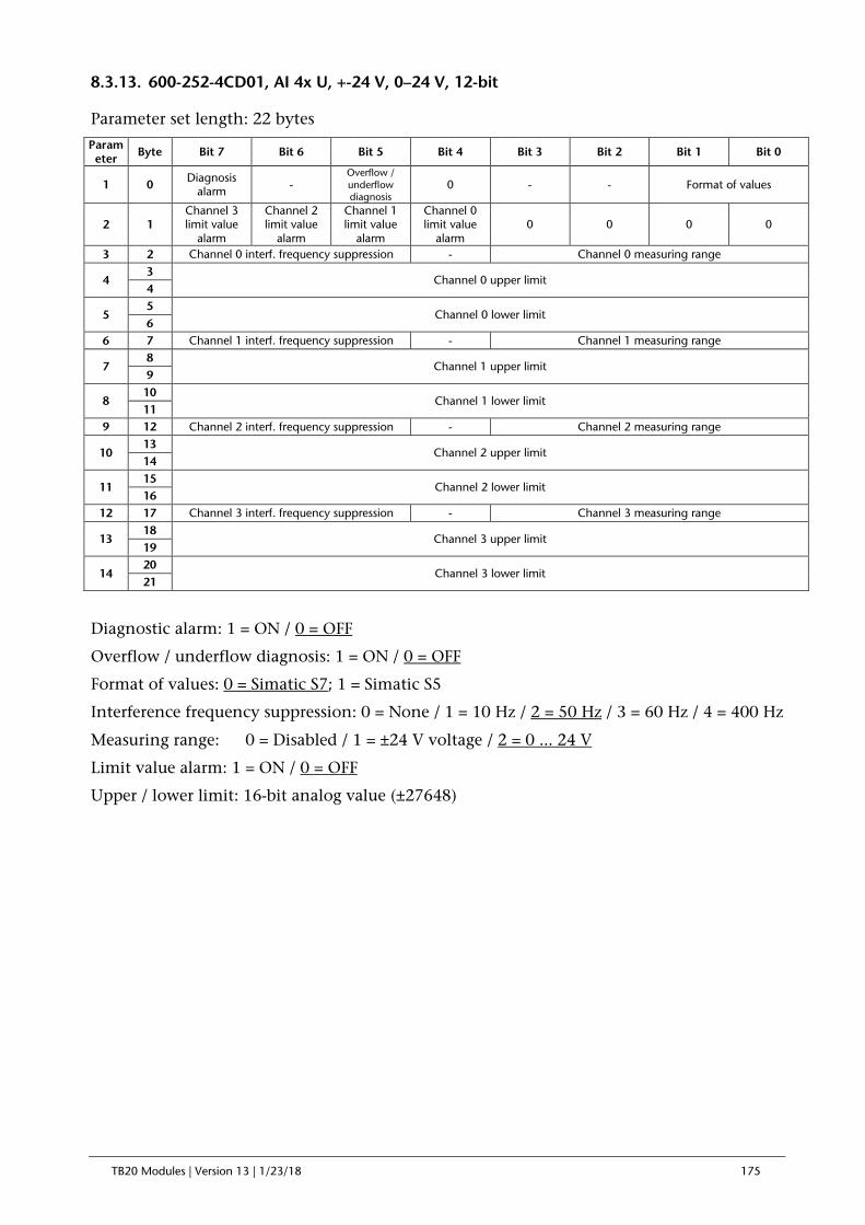
TB20 Modules | Version 13 | 1/23/18 175
8.3.13. 600-252-4CD01, AI 4x U, +-24 V, 0–24 V, 12-bit
Parameter set length: 22 bytes
Parameter Byte Bit 7 Bit 6 Bit 5 Bit 4 Bit 3 Bit 2 Bit 1 Bit 0
1 0 Diagnosis alarm -
Overflow / underflow diagnosis
0 - - Format of values
2 1 Channel 3 limit value
alarm
Channel 2 limit value
alarm
Channel 1 limit value
alarm
Channel 0 limit value
alarm 0 0 0 0
3 2 Channel 0 interf. frequency suppression - Channel 0 measuring range
4 3
Channel 0 upper limit 4
5 5
Channel 0 lower limit 6
6 7 Channel 1 interf. frequency suppression - Channel 1 measuring range
7 8
Channel 1 upper limit 9
8 10
Channel 1 lower limit 11
9 12 Channel 2 interf. frequency suppression - Channel 2 measuring range
10 13
Channel 2 upper limit 14
11 15
Channel 2 lower limit 16
12 17 Channel 3 interf. frequency suppression - Channel 3 measuring range
13 18
Channel 3 upper limit 19
14 20
Channel 3 lower limit 21
Diagnostic alarm: 1 = ON / 0 = OFF
Overflow / underflow diagnosis: 1 = ON / 0 = OFF
Format of values: 0 = Simatic S7; 1 = Simatic S5
Interference frequency suppression: 0 = None / 1 = 10 Hz / 2 = 50 Hz / 3 = 60 Hz / 4 = 400 Hz
Measuring range: 0 = Disabled / 1 = ±24 V voltage / 2 = 0 ... 24 V
Limit value alarm: 1 = ON / 0 = OFF
Upper / lower limit: 16-bit analog value (±27648)

TB20 Modules | Version 13 | 1/23/18 176
8.3.14. 600-252-7DD01, AI 4x U, +-100 V, 0-100 V, Iso., 16-bit
Parameter set length: 23 bytes
Parameter Byte Bit 7 Bit 6 Bit 5 Bit 4 Bit 3 Bit 2 Bit 1 Bit 0
1 0 Mode = 10
2 1 Diagnosis alarm
- Overflow / underflow diagnosis
0 - - Format of values
3 2 Channel 3 limit value
alarm
Channel 2 limit value
alarm
Channel 1 limit value
alarm
Channel 0 limit value
alarm 0 0 0 0
4 3 Channel 0 interf. frequency suppression - Channel 0 measuring range
5 4
Channel 0 upper limit 5
6 6
Channel 0 lower limit 7
7 8 Channel 1 interf. frequency suppression - Channel 1 measuring range
8 9
Channel 1 upper limit 10
9 11
Channel 1 lower limit 12
10 13 Channel 2 interf. frequency suppression - Channel 2 measuring range
11 14
Channel 2 upper limit 15
12 16
Channel 2 lower limit 17
13 18 Channel 3 interf. frequency suppression - Channel 3 measuring range
14 19
Channel 3 upper limit 20
15 21
Channel 3 lower limit 22
Diagnostic alarm: 1 = ON / 0 = OFF
Overflow / underflow diagnosis: 1 = ON / 0 = OFF
Format of values: 0 = Simatic S7; 1 = Simatic S5; 2 = INT16
Interference frequency suppression: 0 = None / 1 = 10 Hz / 2 = 50 Hz / 3 = 60 Hz / 4 = 400 Hz
Measuring range: 0 = Disabled / 1 = ±100 V voltage / 2 = 0 ... 100 V voltage
Limit value alarm: 1 = ON / 0 = OFF
Upper / lower limit: 16-bit analog value (±27648)

TB20 Modules | Version 13 | 1/23/18 177
8.3.15. 600-252-7DH21, AI 8x U, +-100 V, 0-100 V, Iso., 16-bit
Parameter set length: 44 bytes
Parameter Byte Bit 7 Bit 6 Bit 5 Bit 4 Bit 3 Bit 2 Bit 1 Bit 0
1 0 Mode = 10
2 1 Diagnosis alarm
- Overflow / underflow diagnosis
0 - - Format of values
3 2 Channel 3 limit value
alarm
Channel 2 limit value
alarm
Channel 1 limit value
alarm
Channel 0 limit value
alarm 0 0 0 0
4 3 Channel 7 limit value
alarm
Channel 6 limit value
alarm
Channel 5 limit value
alarm
Channel 4 limit value
alarm 0 0 0 0
5 4 Channel 0 interf. frequency suppression - Channel 0 measuring range
6 5
Channel 0 upper limit 6
7 7
Channel 0 lower limit 8
8 9 Channel 1 interf. frequency suppression - Channel 1 measuring range
9 10
Channel 1 upper limit 11
10 12
Channel 1 lower limit 13
11 14 Channel 2 interf. frequency suppression - Channel 2 measuring range
12 15
Channel 2 upper limit 16
13 17
Channel 2 lower limit 18
14 19 Channel 3 interf. frequency suppression - Channel 3 measuring range
15 20
Channel 3 upper limit 21
16 22
Channel 3 lower limit 23
17 24 Channel 4 interf. frequency suppression - Channel 4 measuring range
18 25
Channel 4 upper limit 26
19 27
Channel 4 lower limit 28
20 29 Channel 5 interf. frequency suppression - Channel 5 measuring range
21 30
Channel 5 upper limit 31
22 32
Channel 5 lower limit 33
23 34 Channel 6 interf. frequency suppression - Channel 6 measuring range
24 35
Channel 6 upper limit 36
25 37
Channel 6 lower limit 38
26 39 Channel 7 interf. frequency suppression - Channel 7 measuring range
27 40
Channel 7 upper limit 41
28 42
Channel 7 lower limit 43
Diagnostic alarm: 1 = ON / 0 = OFF
Overflow / underflow diagnosis: 1 = ON / 0 = OFF
Format of values: 0 = Simatic S7; 1 = Simatic S5; 2 = INT16
Interference frequency suppression: 0 = None / 1 = 10 Hz / 2 = 50 Hz / 3 = 60 Hz / 4 = 400 Hz

TB20 Modules | Version 13 | 1/23/18 178
Measuring range: 0 = Disabled / 1 = ±100 V voltage / 2 = 0 ... 100 V voltage
Limit value alarm: 1 = ON / 0 = OFF
Upper / lower limit: 16-bit analog value (±27648)

TB20 Modules | Version 13 | 1/23/18 179
8.3.16. 600-253-4AB01, AI 1/2 x R, RTD, 16-bit, 2/3/4-wire
Parameter set length: 14 bytes
Parameter Byte Bit 7 Bit 6 Bit 5 Bit 4 Bit 3 Bit 2 Bit 1 Bit 0
1 0 Diagnosis alarm -
Overflow / underflow diagnosis
0 Temperature unit 0 0
2 1 - - Channel 1 limit value
alarm
Channel 0 limit value
alarm - -
Channel 1 wire break detection
Channel 0 wire break detection
3 2 Channel 0 interf. frequency suppression - Channel 0 measuring range
4 3 - - - - - Channel 0 sensor type
5 4
Channel 0 upper limit 5
6 6
Channel 0 lower limit 7
7 8 Channel 1 interf. frequency suppression - Channel 1 measuring range
8 9 - - - - - Channel 0 sensor type
2-wire or disabled
9 10
Channel 1 upper limit 11
10 12
Channel 1 lower limit 13
Diagnostic alarm: 1 = ON / 0 = OFF
Overflow / underflow diagnosis: 1 = ON / 0 = OFF
Temperature unit: 0 = °C x 10 / 1 = °F x 10 / 2 = K x 10 (for all temperature measuring ranges)
Wire break detection: ON/OFF
Interference frequency suppression: 0 = None / 1 = 10 Hz / 2 = 50 Hz / 3 = 60 Hz / 4 = 400 Hz
Measuring range: 1 = PT100 (-240 ... 1000°C) / 2 = PT1000 (-240 ... 1000°C) / 3 = Ni100 (-110 ... 295°C) / 4 = Ni1000 (-110 ... 295°C) / 5 = LGNi1000 (-110 ... 295°C) / 6 = 0 ... 150R / 7 = 0 ... 300R / 8 = 0 ... 600R / 9 = 0 ... 3000R / 10 = 0 ... 6000R 11 = PT100 climate (as of FW V1.06) 12 = PT1000 climate (as of FW V1.06)
Sensor type: 0 = disabled / 1= 2-wire / 2 = 3-wire / 3 = 4-wire 3-wire and 4-wire can be selected only on channel 0!
Limit value alarm: 1 = ON / 0 = OFF
Upper / lower limit: 16-bit analog value (±27648)

TB20 Modules | Version 13 | 1/23/18 180
8.3.17. 600-253-4AD01, AI 2/4x R, RTD, 16-bit, 2/3/4-wire
Parameter set length: 26 bytes
Parameter Byte Bit 7 Bit 6 Bit 5 Bit 4 Bit 3 Bit 2 Bit 1 Bit 0
1 0 Diagnosis alarm -
Overflow / underflow diagnosis
0 Temperature unit 0 0
2 1 Channel 3 limit value
alarm
Channel 2 limit value
alarm
Channel 1 limit value
alarm
Channel 0 limit value
alarm
Channel 3 wire break detection
Channel 2 wire break detection
Channel 1 wire break detection
Channel 0 wire break detection
3 2 Channel 0 interf. frequency suppression - Channel 0 measuring range
4 3 - - - - - Channel 0 sensor type
5 4
Channel 0 upper limit 5
6 6
Channel 0 lower limit 7
7 8 Channel 1 interf. frequency suppression - Channel 1 measuring range
8 9 - - - - - Channel 1 sensor type
2-wire or disabled
9 10
Channel 1 upper limit 11
10 12
Channel 1 lower limit 13
11 14 Channel 2 interf. frequency suppression - Channel 2 measuring range 12 15 - - - - - Channel 2 sensor type
13 16
Channel 2 upper limit 17
14 18
Channel 2 lower limit 19
15 20 Channel 3 interf. frequency suppression - Channel 3 measuring range
16 21 - - - - - Channel 3 sensor type
2-wire or disabled
17 22
Channel 3 upper limit 23
18 24
Channel 3 lower limit 25
Diagnostic alarm: 1 = ON / 0 = OFF
Overflow / underflow diagnosis: 1 = ON / 0 = OFF
Temperature unit: 0 = °C x 10 / 1 = °F x 10 / 2 = K x 10 (for all temperature measuring ranges)
Wire break detection: ON/OFF
Interference frequency suppression: 0 = None / 1 = 10 Hz / 2 = 50 Hz / 3 = 60 Hz / 4 = 400 Hz
Measuring range: 1 = PT100 (-240 ... 1000°C) / 2 = PT1000 (-240 ... 1000°C) / 3 = Ni100 (-110 ... 295°C) / 4 = Ni1000 (-110 ... 295°C) / 5 = LGNi1000 (-110 ... 295°C) / 6 = 0 ... 150R / 7 = 0 ... 300R / 8 = 0 ... 600R / 9 = 0 ... 3000R / 10 = 0 ... 6000R 11 = PT100 climate (as of FW V1.06) 12 = PT1000 climate (as of FW V1.06)
Sensor type: 0 = disabled / 1= 2-wire / 2 = 3-wire / 3 = 4-wire 3-wire and 4-wire can be selected only on channel 0 and channel 2!

TB20 Modules | Version 13 | 1/23/18 181
Limit value alarm: 1 = ON / 0 = OFF
Upper / lower limit: 16-bit analog value (±27648)

TB20 Modules | Version 13 | 1/23/18 182
8.3.18. 600-254-4AB01, AI 2 x TC, 16-bit
8.3.19. 600-254-4AB02, AI 2 x TC, Iso., 16-bit
Parameter set length: 14 bytes
Parameter Byte Bit 7 Bit 6 Bit 5 Bit 4 Bit 3 Bit 2 Bit 1 Bit 0
1 0 Diagnosis
alarm -
Overflow / underflow diagnosis
- Temperature unit Format of values
2 1 0 0 Channel 1 limit value
alarm
Channel 0 limit value
alarm 0 0
Channel 1 wire break detection
Channel 0 wire break detection
3 2 Channel 0 interf. frequency suppression - Channel 0 measuring range
4 3 - - - - - Channel 0 temperature compensation
5 4
Channel 0 upper limit 5
6 6
Channel 0 lower limit 7
7 8 Channel 1 interf. frequency suppression - Channel 1 measuring range
8 9 - - - - - Channel 1 temperature compensation
9 10
Channel 1 upper limit 11
10 12
Channel 1 lower limit 13
Diagnostic alarm: 1 = ON / 0 = OFF
Overflow / underflow diagnosis: 1 = ON / 0 = OFF
Representation values: 0 = Simatic S7 / 1 = Simatic S5 (for +-80 mV only)
Temperature unit: 0 = °C x 10 / 1 = °F x 10 / 2 = K x 10 (for all temperature measuring ranges)
Interference frequency suppression: 0 = None / 1 = 10 Hz / 2 = 50 Hz / 3 = 60 Hz / 4 = 400 Hz
Measuring range: 0 = deactivated 1 = -80mV ... +80mV 2 = TC_E (-270°C … 990°C) 3 = TC_J (-210°C ... 1200°C) 4 = TC_K (-270°C … 1380°C) 5 = TC_N (-270°C … 1320°C) 6 = TC_R (-50°C … 1775°C) 7 = TC_S (-50°C … 1775°C) 8 = TC_T (-270°C … 405°C) 9 = TC_B (0°C … 1800°C) 10 = TC_C (0°C … 2320°C) 11 = TC_L (0°C … 900°C)
Temperature compensation: 1= Internal / 2 = External or none / 3 = Via process data outputs
Limit value alarm: 1 = ON / 0 = OFF
Upper / lower limit: 16-bit analog value (±27648)

TB20 Modules | Version 13 | 1/23/18 183
8.3.20. 600-254-4AD01, AI 4 x TC, 16-bit
8.3.21. 600-254-4AD02, AI 4 x TC, Iso., 16-bit
Parameter set length: 26 bytes
Parameter Byte Bit 7 Bit 6 Bit 5 Bit 4 Bit 3 Bit 2 Bit 1 Bit 0
1 0 Diagnosis alarm -
Overflow / underflow diagnosis
- Temperature unit Format of values
2 1 Channel 3 limit value
alarm
Channel 2 limit value
alarm
Channel 1 limit value
alarm
Channel 0 limit value
alarm
Channel 3 wire break detection
Channel 2 wire break detection
Channel 1 wire break detection
Channel 0 wire break detection
3 2 Channel 0 interf. frequency suppression - Channel 0 measuring range
4 3 - - - - - Channel 0 temperature compensation
5 4
Channel 0 upper limit 5
6 6
Channel 0 lower limit 7
7 8 Channel 1 interf. frequency suppression - Channel 1 measuring range 8 9 - - - - - Channel 1 temperature compensation
9 10
Channel 1 upper limit 11
10 12
Channel 1 lower limit 13
11 14 Channel 2 interf. frequency suppression - Channel 2 measuring range
12 15 - - - - - Channel 2 temperature compensation
13 16
Channel 2 upper limit 17
14 18
Channel 2 lower limit 19
15 20 Channel 3 interf. frequency suppression - Channel 3 measuring range 16 21 - - - - - Channel 3 temperature compensation
17 22
Channel 3 upper limit 23
18 24
Channel 3 lower limit 25
Diagnostic alarm: 1 = ON / 0 = OFF Overflow / underflow diagnosis: 1 = ON / 0 = OFF Representation values: 0 = Simatic S7 / 1 = Simatic S5 (for +-80 mV only) Temperature unit: 0 = °C x 10 / 1 = °F x 10 / 2 = K x 10 (for all temperature measuring ranges) Interference frequency suppression: 0 = None / 1 = 10 Hz / 2 = 50 Hz / 3 = 60 Hz / 4 = 400 Hz Measuring range: 0 = deactivated 1 = -80mV ... +80mV 2 = TC_E (-270°C … 990°C) 3 = TC_J (-210°C ... 1200°C) 4 = TC_K (-270°C … 1380°C) 5 = TC_N (-270°C … 1320°C) 6 = TC_R (-50°C … 1775°C) 7 = TC_S (-50°C … 1775°C) 8 = TC_T (-270°C … 405°C) 9 = TC_B (0°C … 1800°C) 10 = TC_C (0°C … 2320°C) 11 = TC_L (0°C … 900°C) Temperature compensation: 1= Internal / 2 = External or none / 3 = Via process data outputs Limit value alarm: 1 = ON / 0 = OFF Upper / lower limit: 16-bit analog value (±27648)

TB20 Modules | Version 13 | 1/23/18 184
8.3.22. 600-254-4AH22, AI 8 x TC, Iso., 16-bit
Parameter set length: 51 bytes
Parameter Byte Bit 7 Bit 6 Bit 5 Bit 4 Bit 3 Bit 2 Bit 1 Bit 0
1 0 Diagnosis alarm -
Overflow / underflow diagnosis
- Temperature unit Format of values
2 1 Channel 3 limit value
alarm
Channel 2 limit value
alarm
Channel 1 limit value
alarm
Channel 0 limit value
alarm
Channel 3 wire break detection
Channel 2 wire break detection
Channel 1 wire break detection
Channel 0 wire break detection
3 2 Channel 3 limit value
alarm
Channel 2 limit value
alarm
Channel 1 limit value
alarm
Channel 0 limit value
alarm
Channel 7 wire break detection
Channel 6 wire break detection
Channel 5 wire break detection
Channel 4 wire break detection
4 3 Channel 0 interf. frequency suppression - Channel 0 measuring range 5 4 - - - - - Channel 0 temperature compensation
6 5
Channel 0 upper limit 6
7 7
Channel 0 lower limit 8
8 9 Channel 1 interf. frequency suppression - Channel 1 measuring range
9 10 - - - - - Channel 1 temperature compensation
10 11
Channel 1 upper limit 12
11 13
Channel 1 lower limit 14
12 15 Channel 2 interf. frequency suppression - Channel 2 measuring range 13 16 - - - - - Channel 2 temperature compensation
14 17
Channel 2 upper limit 18
15 19
Channel 2 lower limit 20
16 21 Channel 3 interf. frequency suppression - Channel 3 measuring range
17 22 - - - - - Channel 3 temperature compensation
18 23
Channel 3 upper limit 24
19 25
Channel 3 lower limit 26
20 27 Channel 4 interf. frequency suppression - Channel 4 measuring range 21 28 - - - - - Channel 4 temperature compensation
22 29
Channel 4 upper limit 30
23 31
Channel 4 lower limit 32
24 33 Channel 5 interf. frequency suppression - Channel 5 measuring range
25 34 - - - - - Channel 5 temperature compensation
26 35
Channel 5 upper limit 36
27 37
Channel 5 lower limit 38
28 39 Channel 6 interf. frequency suppression - Channel 6 measuring range 29 40 - - - - - Channel 6 temperature compensation
30 41
Channel 6 upper limit 42
31 43
Channel 6 lower limit 44
32 45 Channel 7 interf. frequency suppression - Channel 7 measuring range
33 46 - - - - - Channel 7 temperature compensation
34 47
Channel 7 upper limit 48
35 49
Channel 7 lower limit 50

TB20 Modules | Version 13 | 1/23/18 185
Diagnostic alarm: 1 = ON / 0 = OFF
Overflow / underflow diagnosis: 1 = ON / 0 = OFF
Representation values: 0 = Simatic S7 / 1 = Simatic S5 (for +-80 mV only)
Temperature unit: 0 = °C x 10 / 1 = °F x 10 / 2 = K x 10 (for all temperature measuring ranges)
Interference frequency suppression: 0 = None / 1 = 10 Hz / 2 = 50 Hz / 3 = 60 Hz / 4 = 400 Hz
Measuring range: 0 = deactivated 1 = -80mV ... +80mV 2 = TC_E (-270°C … 990°C) 3 = TC_J (-210°C ... 1200°C) 4 = TC_K (-270°C … 1380°C) 5 = TC_N (-270°C … 1320°C) 6 = TC_R (-50°C … 1775°C) 7 = TC_S (-50°C … 1775°C) 8 = TC_T (-270°C … 405°C) 9 = TC_B (0°C … 1800°C) 10 = TC_C (0°C … 2320°C) 11 = TC_L (0°C … 900°C)
Temperature compensation: 1= Internal / 2 = External or none / 3 = Via process data outputs
Limit value alarm: 1 = ON / 0 = OFF
Upper / lower limit: 16-bit analog value (±27648)

TB20 Modules | Version 13 | 1/23/18 186
8.4. Analog Output Modules
8.4.1. 600-260-4AB01, AO 2 x I, 0/4–20 mA, 12-bit
Parameter set length: 7 bytes
Parameter Byte Bit 7 Bit 6 Bit 5 Bit 4 Bit 3 Bit 2 Bit 1 Bit 0
1 0 Diagnosis alarm - - 1 - - Format of values
2 1 Channel 0 wire break detection
Channel 0 behavior at CPU-STOP Channel 0 output range
3 2
Channel 0 substitute value 3
4 4 Channel 1 wire break detection
Channel 1 behavior at CPU-STOP Channel 1 output range
5 5
Channel 1 substitute value 6
Diagnostic alarm: 1 = ON / 0 = OFF
Format of values: 0 = Simatic S7; 1 = Simatic S5; 2 = INT16
Wire break detection: 1 = On/ 0 = Off
Output ranges: 0 = Disabled / 1 = 0–20 mA current / 2 = 4 ... 20 mA current
Behavior at CPU-STOP: 0 = Outputs de-energized / 1= Retain last value / 2 = Apply substitute value
Substitute value: 16-bit analog value (±27648)

TB20 Modules | Version 13 | 1/23/18 187
8.4.2. 600-260-4AD01, AO 4 x I, 0/4–20 mA, 12-bit
Parameter set length: 13 bytes
Parameter Byte Bit 7 Bit 6 Bit 5 Bit 4 Bit 3 Bit 2 Bit 1 Bit 0
1 0 Diagnosis alarm - - 1 - - Format of values
2 1 Channel 0 wire break detection
Channel 0 behavior at CPU-STOP Channel 0 output range
3 2
Channel 0 substitute value 3
4 4 Channel 1 wire break detection
Channel 1 behavior at CPU-STOP Channel 1 output range
5 5
Channel 1 substitute value 6
6 7 Channel 2 wire break detection
Channel 2 behavior at CPU-STOP Channel 2 output range
7 8
Channel 2 substitute value 9
8 10 Channel 3 wire break detection
Channel 3 behavior at CPU-STOP Channel 3 output range
9 11
Channel 3 substitute value 12
Diagnostic alarm: 1 = ON / 0 = OFF
Format of values: 0 = Simatic S7; 1 = Simatic S5; 2 = INT16
Wire break detection: 1 = On/ 0 = Off
Output ranges: 0 = deactivated / 1 = 0 ... 20 mA current/ 2 = 4 ... 20 mA current
Behavior at CPU-STOP 0 = Outputs de-energized / 1= Retain last value / 2 = Apply substitute value
Substitute value: 16-bit analog value (±27648)

TB20 Modules | Version 13 | 1/23/18 188
8.4.3. 600-261-4AB01, AO 2x U, +-10 V, 0–10 V, 1–5 V, 12-bit
Parameter set length: 7 bytes
Parameter Byte Bit 7 Bit 6 Bit 5 Bit 4 Bit 3 Bit 2 Bit 1 Bit 0
1 0 Diagnosis alarm - - 0 - - Format of values
2 1 0 Channel 0 behavior at CPU-STOP Channel 0 output range
3 2
Channel 0 substitute value 3
4 4 0 Channel 1 behavior at CPU-STOP Channel 1 output range
5 5
Channel 1 substitute value 6
Diagnostic alarm: 1 = ON / 0 = OFF
Format of values: 0 = Simatic S7; 1 = Simatic S5; 2 = INT16
Output range: 0 = Disabled / 1 = ±10 V voltage / 2 = 0 ... 10 V voltage/ 3 = 1 ... 5 V voltage
Behavior at CPU-STOP 0 = Outputs de-energized / 1= Retain last value / 2 = Apply substitute value
Substitute value: 16-bit analog value (±27648)

TB20 Modules | Version 13 | 1/23/18 189
8.4.4. 600-261-4AD01, AO 4 x U, ±10 V, 0–10 V, 1–5 V, 12-bit
Parameter set length: 13 bytes
Parameter Byte Bit 7 Bit 6 Bit 5 Bit 4 Bit 3 Bit 2 Bit 1 Bit 0
1 0 Diagnosis alarm - - 0 - - Format of values
2 1 0 Channel 0 behavior at CPU-STOP Channel 0 output range
3 2
Channel 0 substitute value 3
4 4 0 Channel 1 behavior at CPU-STOP Channel 1 output range
5 5
Channel 1 substitute value 6
6 7 0 Channel 2 behavior at CPU-STOP Channel 2 output range
7 8
Channel 2 substitute value 9
8 10 0 Channel 3 behavior at CPU-STOP Channel 3 output range
9 11
Channel 3 substitute value 12
Diagnostic alarm: 1 = ON / 0 = OFF
Format of values: 0 = Simatic S7; 1 = Simatic S5; 2 = INT16
Output range: 0 = Disabled / 1 = ±10 V voltage / 2 = 0 ... 10 V voltage/ 3 = 1 ... 5 V
Behavior at CPU-STOP 0 = Outputs de-energized / 1= Retain last value / 2 = Apply substitute value
Substitute value: 16-bit analog value (±27648)
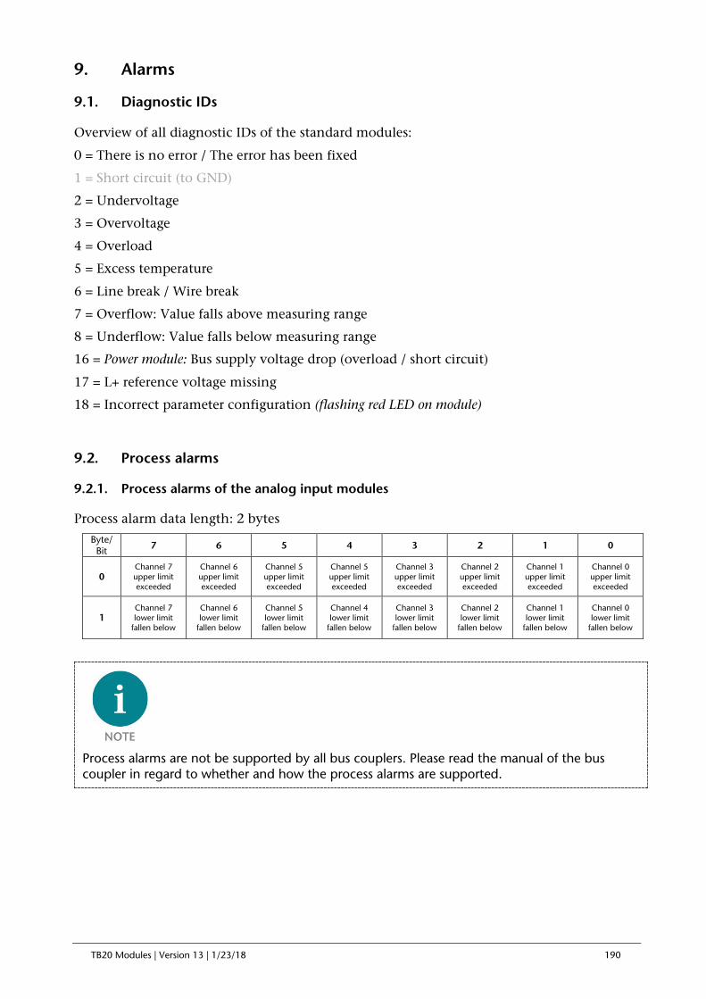
TB20 Modules | Version 13 | 1/23/18 190
9. Alarms
9.1. Diagnostic IDs
Overview of all diagnostic IDs of the standard modules:
0 = There is no error / The error has been fixed
1 = Short circuit (to GND)
2 = Undervoltage
3 = Overvoltage
4 = Overload
5 = Excess temperature
6 = Line break / Wire break
7 = Overflow: Value falls above measuring range
8 = Underflow: Value falls below measuring range
16 = Power module: Bus supply voltage drop (overload / short circuit)
17 = L+ reference voltage missing
18 = Incorrect parameter configuration (flashing red LED on module)
9.2. Process alarms
9.2.1. Process alarms of the analog input modules
Process alarm data length: 2 bytes
Byte/Bit 7 6 5 4 3 2 1 0
0 Channel 7 upper limit exceeded
Channel 6 upper limit exceeded
Channel 5 upper limit exceeded
Channel 5 upper limit exceeded
Channel 3 upper limit exceeded
Channel 2 upper limit exceeded
Channel 1 upper limit exceeded
Channel 0 upper limit exceeded
1 Channel 7 lower limit
fallen below
Channel 6 lower limit
fallen below
Channel 5 lower limit
fallen below
Channel 4 lower limit
fallen below
Channel 3 lower limit
fallen below
Channel 2 lower limit
fallen below
Channel 1 lower limit
fallen below
Channel 0 lower limit
fallen below
Process alarms are not be supported by all bus couplers. Please read the manual of the bus coupler in regard to whether and how the process alarms are supported.

TB20 Modules | Version 13 | 1/23/18 191
10. Dimensions

TB20 Modules | Version 13 | 1/23/18 192
11. Spare parts
11.1. Base modules
11.1.1. 14 mm width standard base module
The 14 mm standard base module is available in sets of five with order no. 600-900-9AA01.
11.1.2. 25 mm width base module
The 25 mm standard base module is available in sets of five with order no. 600-900-9AA21.
11.1.3. Power and isolation base module
The power and isolation base module is available in sets of five with order no. 600-900-9BA01.

TB20 Modules | Version 13 | 1/23/18 193
11.1.4. Power base module
The power base module is available in sets of five with order no. 600-900-9CA01.
It can be used with the power module (600-700-0AA01) and with all bus couplers.
11.2. Front connectors
11.2.1. 10-terminal front connector
The 10-terminal front connector is available in sets of five with order no. 600-910-9AJ01.
11.2.2. 20-terminal front connector
The 20-pin front connector is available in sets of five with order no. 600-910-9AT21.

TB20 Modules | Version 13 | 1/23/18 194
11.3. Electronic modules
Electronic modules can be ordered as spare parts with the order number of the original product. Electronic modules are always sent as a complete assembly, including the corresponding base module and front connector.
11.4. Final cover
The final cover is available in sets of five with order no. 600-920-9AA01.