manual - diversity data and messaging tests, nqdi tests
TRANSCRIPT

A Rohde & Schwarz Company
Data and Messaging Tests Manual
March 2013
SwissQual® License AG Allmendweg 8 CH-4528 Zuchwil Switzerland
t +41 32 686 65 65 f +41 32 686 65 66 e [email protected] www.swissqual.com
Part Number: 16-100-200510 Rev 1.24

SwissQual has made every effort to ensure that eventual instructions contained in the document are adequate and free of errors and omissions. SwissQual will, if necessary, explain issues which may not be covered by the documents. SwissQual’s liability for any errors in the documents is limited to the correction of errors and the aforementioned advisory services.
Copyright 2000 - 2013 SwissQual AG. All rights reserved.
No part of this publication may be copied, distributed, transmitted, transcribed, stored in a retrieval system, or translated into any human or computer language without the prior written permission of SwissQual AG.
Confidential materials.
All information in this document is regarded as commercial valuable, protected and privileged intellectual property, and is provided under the terms of existing Non-Disclosure Agreements or as commercial-in-confidence material.
When you refer to a SwissQual technology or product, you must acknowledge the respective text or logo trademark somewhere in your text.
SwissQual®, Seven.Five®, SQuad®, QualiPoc®, NetQual®, VQuad®, Diversity® as well as the following logos are registered trademarks of SwissQual AG.
Diversity Explorer™, Diversity Ranger™, Diversity Unattended™, NiNA+™, NiNA™, NQAgent™, NQComm™, NQDI™, NQTM™, NQView™, NQWeb™, QPControl™, QPView™, QualiPoc Freerider™, QualiPoc iQ™, QualiPoc Mobile™, QualiPoc Static™, QualiWatch-M™, QualiWatch-S™, SystemInspector™, TestManager™, VMon™, VQuad-HD™ are trademarks of SwissQual AG.
SwissQual acknowledges the following trademarks for company names and products:
Adobe®, Adobe Acrobat®, and Adobe Postscript® are trademarks of Adobe Systems Incorporated.
Apple is a trademark of Apple Computer, Inc.
DIMENSION®, LATITUDE®, and OPTIPLEX® are registered trademarks of Dell Inc.
ELEKTROBIT® is a registered trademark of Elektrobit Group Plc.
Google® is a registered trademark of Google Inc.
Intel®, Intel Itanium®, Intel Pentium®, and Intel Xeon™ are trademarks or registered trademarks of Intel Corporation.
INTERNET EXPLORER®, SMARTPHONE®, TABLET® are registered trademarks of Microsoft Corporation.
Java™ is a U.S. trademark of Sun Microsystems, Inc.
Linux® is a registered trademark of Linus Torvalds.
Microsoft®, Microsoft Windows®, Microsoft Windows NT®, and Windows Vista® are either registered trademarks or trademarks of Microsoft Corporation in the United States and/or other countries U.S.
NOKIA® is a registered trademark of Nokia Corporation.
Oracle® is a registered US trademark of Oracle Corporation, Redwood City, California.
SAMSUNG® is a registered trademark of Samsung Corporation.
SIERRA WIRELESS® is a registered trademark of Sierra Wireless, Inc.
TRIMBLE® is a registered trademark of Trimble Navigation Limited.
U-BLOX® is a registered trademark of u-blox Holding AG.
UNIX® is a registered trademark of The Open Group.
Data and Messaging Tests Manual
© 2000 - 2013 SwissQual AG
Contents | CONFIDENTIAL MATERIALS
ii
Contents 1 Introduction .......................................................................................................................................... 1
Overview of a Measurement Cycle ........................................................................................................ 1
Reference Documentation ..................................................................................................................... 3
2 Ping Test ............................................................................................................................................... 4
Objective and Purpose .......................................................................................................................... 4
Basic Function ....................................................................................................................................... 4
IPv6 Support .......................................................................................................................................... 4
Forcing Diversity to Use a Specific IP Version for a Test ................................................................ 5
IPv6 Address Format ........................................................................................................................ 6 IPv4 and IPv6 Traffic in NQDI .......................................................................................................... 6
Result Analysis ...................................................................................................................................... 7
3 Ping Trace Test .................................................................................................................................... 9
IPv6 Support .......................................................................................................................................... 9
Objective and Purpose .......................................................................................................................... 9
Basic Function ....................................................................................................................................... 9 Results Analysis .................................................................................................................................... 9
4 FTP Test .............................................................................................................................................. 11
Objective and Purpose ........................................................................................................................ 11
Basic Function ..................................................................................................................................... 11
Impact of ‘Send Buffer Size’ parameter value ................................................................................ 11
Results Analysis .................................................................................................................................. 12
5 HTTP Browser Test............................................................................................................................ 14
Objective and Purpose ........................................................................................................................ 14
Basic Function ..................................................................................................................................... 14
Results Analysis .................................................................................................................................. 14
6 HTTP Transfer Test............................................................................................................................ 16
Objective and Purpose ........................................................................................................................ 16 Basic Function ..................................................................................................................................... 16
Results Analysis .................................................................................................................................. 16
7 Capacity Test ..................................................................................................................................... 18
Objective and Purpose ........................................................................................................................ 18
Basic Function ..................................................................................................................................... 18 Result Analysis .................................................................................................................................... 19
8 UDP Downlink Test ............................................................................................................................ 21
Objective and Purpose ........................................................................................................................ 21
Data and Messaging Tests Manual
© 2000 - 2013 SwissQual AG
Contents | CONFIDENTIAL MATERIALS
iii
Basic Function ..................................................................................................................................... 21
Results Analysis .................................................................................................................................. 21
9 UDP Plus Test .................................................................................................................................... 23
Objective and Purpose ........................................................................................................................ 23
Basic Function ..................................................................................................................................... 23
Results Analysis UDPPlus ................................................................................................................... 23
10 Email Send Test ................................................................................................................................. 26
Objective and Purpose ........................................................................................................................ 26 Basic Function ..................................................................................................................................... 26
Results Analysis .................................................................................................................................. 26
11 Email Receive Test ............................................................................................................................ 28
Objective and Purpose ........................................................................................................................ 28
Basic Function ..................................................................................................................................... 28 Results Analysis .................................................................................................................................. 28
12 GPRS Attach Test .............................................................................................................................. 30
Objective and Purpose ........................................................................................................................ 30
Basic Function ..................................................................................................................................... 30
Results Analysis .................................................................................................................................. 30
13 GPRS Detach Test ............................................................................................................................. 32
Objective and Purpose ........................................................................................................................ 32
Basic Function ..................................................................................................................................... 32
Results Analysis .................................................................................................................................. 32
14 PDP Activation Test........................................................................................................................... 34
Objective and Purpose ........................................................................................................................ 34
Basic Function ..................................................................................................................................... 34 Results Analysis .................................................................................................................................. 34
15 PDP Deactivation Test ...................................................................................................................... 36
Objective and Purpose ........................................................................................................................ 36
Basic Function ..................................................................................................................................... 36
Results Analysis .................................................................................................................................. 36
16 WAP Test ............................................................................................................................................ 37
Objective and Purpose ........................................................................................................................ 37
Basic Function ..................................................................................................................................... 37
Results Analysis .................................................................................................................................. 37
17 SMS Send Test ................................................................................................................................... 39
Objective and Purpose ........................................................................................................................ 39
Data and Messaging Tests Manual
© 2000 - 2013 SwissQual AG
Contents | CONFIDENTIAL MATERIALS
iv
Basic Function ..................................................................................................................................... 39
Results Analysis .................................................................................................................................. 39
18 SMS Receive Test .............................................................................................................................. 41
Objective and Purpose ........................................................................................................................ 41
Basic Function ..................................................................................................................................... 41
Results Analysis .................................................................................................................................. 41
19 MMS Send Test .................................................................................................................................. 43
Phone Configuration ............................................................................................................................ 43 Objective and Purpose ........................................................................................................................ 43
Basic Function ..................................................................................................................................... 43
Results Analysis .................................................................................................................................. 43
Trigger Points MMS Sender ................................................................................................................ 48
20 MMS Receive Test ............................................................................................................................. 49
Objective and Purpose ........................................................................................................................ 49
Basic Function ..................................................................................................................................... 49
Results Analysis .................................................................................................................................. 49
Trigger Points MMS Receiver .............................................................................................................. 53
A Port Usage and Firewall Settings ..................................................................................................... 54
Dialup Network Connections ............................................................................................................... 54
B Reducing the Effective Pause Time ................................................................................................. 59
Figures Figure 1-1 Overview of the idle times and pauses in a measurement cycle ..................................................... 1
Figure 1-2 NDIS post connect delay in NQDI. ................................................................................................... 2
Figure 2-1 Ping Test - Basic Function ............................................................................................................... 4
Figure 2-2 Network adapter properties .............................................................................................................. 5
Figure 2-3 IPv4 and IPv6 traffic throughput in NQDI ......................................................................................... 7 Figure 2-4 Ping Test - NQDI Result Analysis Window ...................................................................................... 8
Figure 3-1 Ping Trace Test - Basic Function ..................................................................................................... 9
Figure 3-2 Ping Trace Test - NQDI Result Analysis Window .......................................................................... 10
Figure 4-1 FTP Test - Basic Function .............................................................................................................. 11
Figure 4-2 FTP Test - NQDI Result Analysis Window ..................................................................................... 13 Figure 5-1 Test – HTTP Browser Test - Basic Function .................................................................................. 14
Figure 5-2 HTTP Browser Test - NQDI Result Analysis Window .................................................................... 15
Figure 6-1 Test – HTTP Transfer Test - Basic Function ................................................................................. 16
Figure 6-2 HTTP Transfer Test - NQDI Result Analysis Window.................................................................... 17
Figure 7-1 Overview of a Capacity test ........................................................................................................... 18
Figure 7-2 Results of Capacity test ................................................................................................................. 20
Data and Messaging Tests Manual
© 2000 - 2013 SwissQual AG
Contents | CONFIDENTIAL MATERIALS
v
Figure 8-1 UDP Downlink Test – Basic Function ............................................................................................ 21
Figure 8-2 UDP Downlink Test - NQDI Result Analysis Window .................................................................... 22 Figure 9-1 UDP Plus Test – Basic Function .................................................................................................... 23
Figure 9-2 UDP Plus Test - NQDI Result Analysis Window ............................................................................ 25
Figure 10-1 Email Send Test – Basic Function ............................................................................................... 26
Figure 10-2 Email Send Test - NQDI Result Analysis Window ....................................................................... 27
Figure 11-1 Email Receive Test – Basic Function .......................................................................................... 28
Figure 11-2 Email Receive Test - NQDI Result Analysis Window .................................................................. 29 Figure 12-1 GPRS Attach Test – Basic Function ............................................................................................ 30
Figure 12-2 GPRS Attach Analysis window (NQDI) ........................................................................................ 31
Figure 13-1 GPRS Detach Test – Basic Function ........................................................................................... 32
Figure 13-2 GPRSDetach Analysis Window (NQDI) ....................................................................................... 33
Figure 14-1 PDP Activation Test – Basic Function ......................................................................................... 34 Figure 14-2 PDP Activation Test - NQDI Result Analysis Window ................................................................. 35
Figure 15-1 PDP Deactivation Test – Basic Function ..................................................................................... 36
Figure 15-2 PDP Deactivation Test - NQDI Result Analysis Window ............................................................. 36
Figure 16-1 WAP Test - NQDI Result Analysis Window ................................................................................. 38
Figure 17-1 SMSSend Test Diagram .............................................................................................................. 39
Figure 17-2 SMS Send test - Result Analysis Window ................................................................................... 39 Figure 18-1 SMS Receive Test - Basic Function ........................................................................................... 41
Figure 18-2 SMS Receive Test - NQDI Result Analysis Window.................................................................... 42
Figure 18-3 SMS Receive Test - NQDI Result Analysis Window.................................................................... 42
Figure 19-1 MMS Send Test – Basic Function ................................................................................................ 43
Figure 19-2 MMS Send Test - NQDI Result Analysis Window ........................................................................ 45
Figure 19-3 MMS Send Test - NQDI Result Analysis Window ........................................................................ 46 Figure 19-4 MMS Send Test - NQDI Result Analysis Window ........................................................................ 47
Figure 20-1 MMS Receive Test – Basic Function ........................................................................................... 49
Figure 20-2 MMS Receive Test - NQDI Result Analysis Window ................................................................... 50
Figure 20-3 MMS Receive Test - NQDI Result Analysis Window ................................................................... 51
Figure 20-4 MMS Receive Test - NQDI Result Analysis Window ................................................................... 52 Figure A-1 GPRS markers in the GSM Analysis Window ............................................................................... 55
Figure A-2 GPRS markers in the Test Specific Analysis Window ................................................................... 56
Figure A-3 GPRS Markers in the Map Window ............................................................................................... 56
Figure A-4 PDP Context Activation after GPRS Dial ....................................................................................... 57
Figure A-5 GPRS PDP Context Activation ...................................................................................................... 57
Figure A-6 Data selection for GPRS dial-up connect failures ......................................................................... 58
Tables Table 2-1 Timing of actions during a Ping Test ................................................................................................. 4
Table 2-2 Ping Test - Result Analysis ............................................................................................................... 7
Data and Messaging Tests Manual
© 2000 - 2013 SwissQual AG
Contents | CONFIDENTIAL MATERIALS
vi
Table 3-1 Ping Trace Test - Result Analysis ..................................................................................................... 9
Table 4-1 Timing of actions during an FTP Test ............................................................................................. 11 Table 4-2 FTP Test - Result Analysis .............................................................................................................. 12
Table 5-1 HTTP Browser Test - Result Analysis ............................................................................................. 14
Table 6-1 Timing of actions during an HTTP Transfer Test ............................................................................ 16
Table 6-2 HTTP Transfer Test - Result Analysis ............................................................................................. 16
Table 7-1 Description of the Capacity test data .............................................................................................. 19
Table 8-1 UDP Downlink test - Result Analysis .............................................................................................. 21 Table 9-1 UDP Plus Test - Result Analysis ..................................................................................................... 24
Table 9-2 UDP Plus Test - Values in Statistics Register ................................................................................. 24
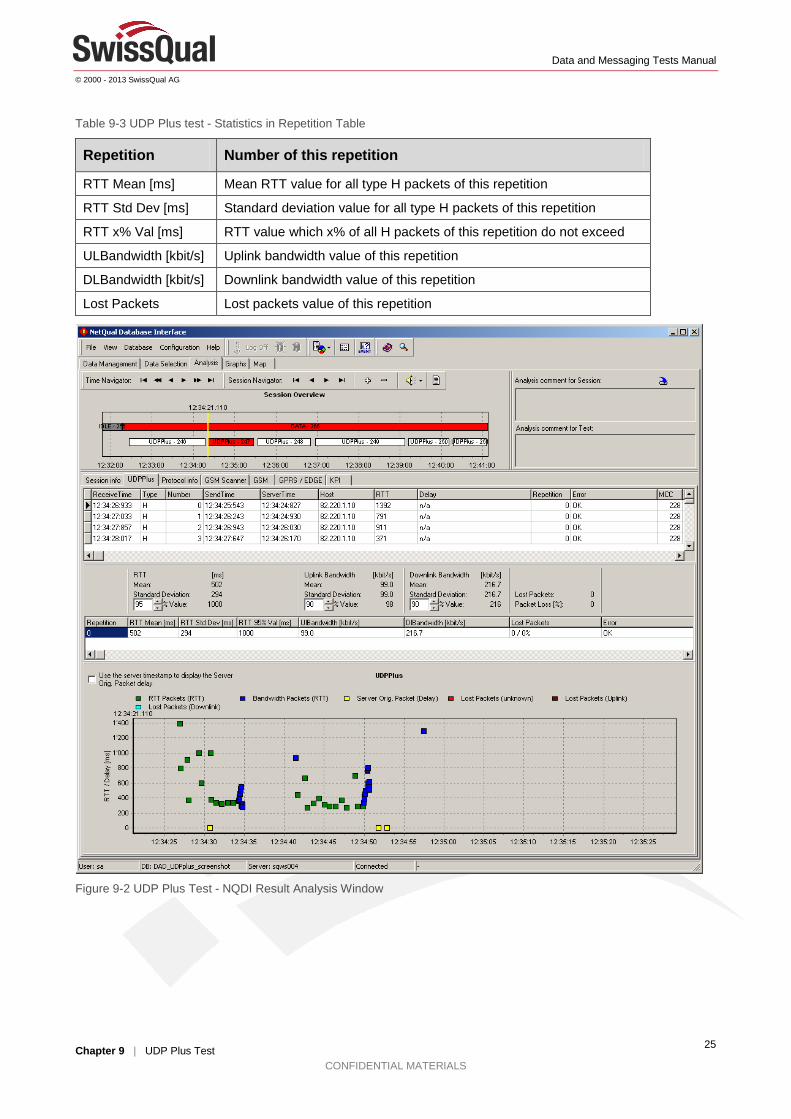
Table 9-3 UDP Plus test - Statistics in Repetition Table ................................................................................. 25
Table 10-1 Email Send Test - Result Analysis ................................................................................................ 26
Table 11-1 Email Receive Test - Result Analysis ........................................................................................... 28 Table 12-1 Timing of actions during a GPRS Attach Test ............................................................................... 30
Table 13-1 Timing of actions during a GPRS Detach Test ............................................................................. 32
Table 14-1 Timing of actions during a PDP Activation Test ............................................................................ 34
Table 15-1 Timing of actions during a PDP Deactivation Test ........................................................................ 36
Table 16-1 WAP Test - Result Analysis .......................................................................................................... 37
Table 17-1 SMS Send Test - Result Analysis ................................................................................................. 40 Table 18-1 SMS Receive Test - Result Analysis ............................................................................................. 41
Table 19-1 MMS Send Test - Result Analysis ................................................................................................. 43
Table 20-1 MMS Receive Test - Result Analysis ............................................................................................ 49
Table A-1 Port Number Listing ........................................................................................................................ 54
Table A-2 UDP Ports ....................................................................................................................................... 54
Data and Messaging Tests Manual
© 2000 - 2013 SwissQual AG
Chapter 1 | Introduction CONFIDENTIAL MATERIALS
1
1 Introduction This document describes the Data and Messaging tests available with the Diversity Measurement Units, SwissQual’s Subscriber Experience Management system for audio, data, messaging and video quality.
Each test is handled in a separate chapter, consisting of a description of the test flow and the result analysis. Analysis is presented with NQDI, SwissQual’s post processing application. Were necessary and appropriate, in depth detail information is provided as well. The appendix outlines general information as well other kind of ‘nice to know’ descriptions.
Note: Please note that this document does not describe how to setup Diversity nor does it deal with configuring the data and messaging tests. These topics are provided in document [1].
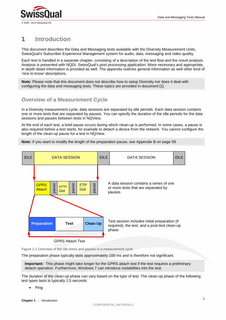
Overview of a Measurement Cycle In a Diversity measurement cycle, data sessions are separated by idle periods. Each data session contains one or more tests that are separated by pauses. You can specify the duration of the idle periods for the data sessions and pauses between tests in NQView.
At the end of each test, a brief pause occurs during which clean-up is performed. In some cases, a pause is also required before a test starts, for example to detach a device from the network. You cannot configure the length of the clean-up pause for a test in NQView.
Note: If you want to modify the length of the preparation pause, see Appendix B on page 59.
Figure 1-1 Overview of the idle times and pauses in a measurement cycle
The preparation phase typically lasts approximately 100 ms and is therefore not significant.
Important: This phase might take longer for the GPRS attach test if the test requires a preliminary detach operation. Furthermore, Windows 7 can introduce instabilities into the test.
The duration of the clean-up phase can vary based on the type of test. The clean-up phase of the following test types lasts is typically 1.5 seconds:
• Ping
IDLE IDLE DATA SESSION DATA SESSION IDLE
paus
e GPRS Attach
HTTP Get pa
use FTP
Get
paus
e
Preparation Test Clean Up
A data session contains a series of one or more tests that are separated by pauses.
Test session includes initial preparation (if required), the test, and a post-test clean-up phase.
GPRS Attach Test
Data and Messaging Tests Manual
© 2000 - 2013 SwissQual AG
Chapter 1 | Introduction CONFIDENTIAL MATERIALS
2
• GPRS Attach
• GPRS Detach
• PDP Activation
• PDP Deactivation
• SMS Send
• SMS Receive
The clean-up phase for the following test types typically lasts 3 seconds:
• HTTP Transfer
• HTTP Browser
• FTP, Capacity
• IPERF
• Ping Trace
• UDP
• MMS send
• MMS receive
Note: In the worst case, the duration of the clean-up phase might double.
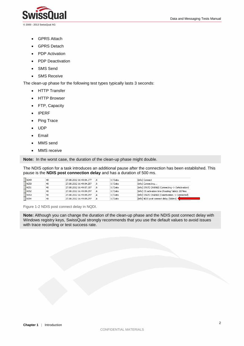
The NDIS option for a task introduces an additional pause after the connection has been established. This pause is the NDIS post connection delay and has a duration of 500 ms.
Figure 1-2 NDIS post connect delay in NQDI.
Note: Although you can change the duration of the clean-up phase and the NDIS post connect delay with Windows registry keys, SwissQual strongly recommends that you use the default values to avoid issues with trace recording or test success rate.

Data and Messaging Tests Manual
© 2000 - 2013 SwissQual AG
Chapter 1 | Introduction CONFIDENTIAL MATERIALS
3
Reference Documentation
Reference Document
[1] Manual – NetQual - NQView
[2] Manual – NQDI - KPI Users Guide
Data and Messaging Tests Manual
© 2000 - 2013 SwissQual AG
Chapter 2 | Ping Test CONFIDENTIAL MATERIALS
4
2 Ping Test
Objective and Purpose The ping test verifies the connectivity between two hosts within an IP data network. The test measures the Round Trip Time (RTT) between request and reply of multiple pings by sending ICMP messages. The test is successful when all ICMP Echo Requests are being acknowledged by the corresponding ICMP Echo Reply message. If any of the pings is not successfully confirmed within timeout, the test is considered as failed.
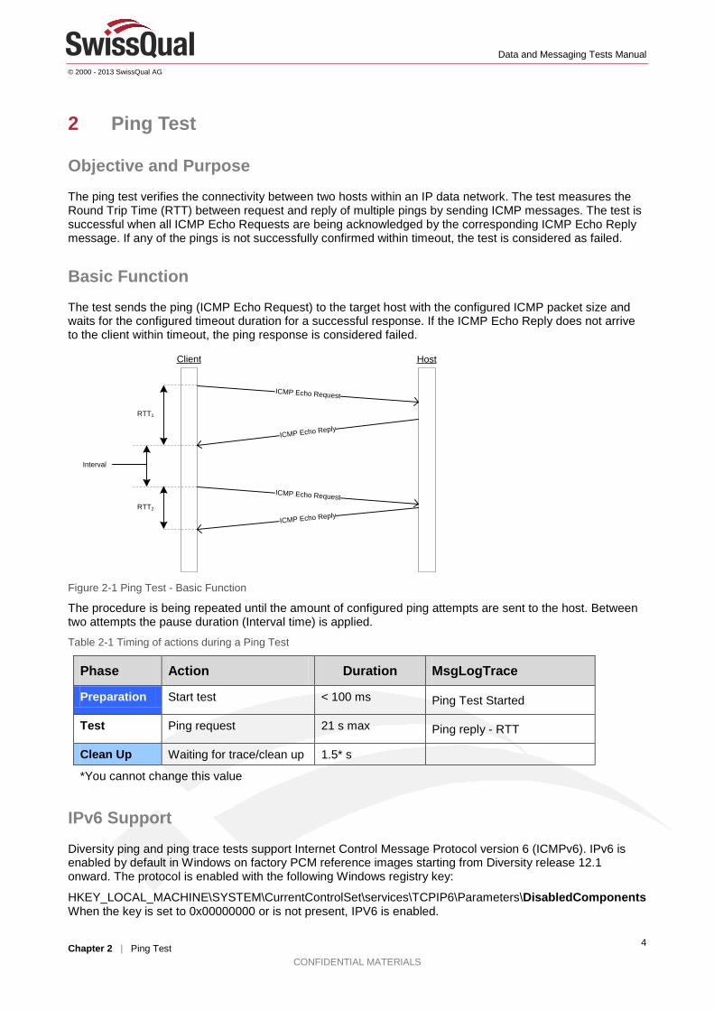
Basic Function The test sends the ping (ICMP Echo Request) to the target host with the configured ICMP packet size and waits for the configured timeout duration for a successful response. If the ICMP Echo Reply does not arrive to the client within timeout, the ping response is considered failed.
ICMP Echo Request
ICMP Echo Reply
ICMP Echo Request
ICMP Echo Reply
RTT1
RTT2
Interval
Client Host
Figure 2-1 Ping Test - Basic Function
The procedure is being repeated until the amount of configured ping attempts are sent to the host. Between two attempts the pause duration (Interval time) is applied.
Table 2-1 Timing of actions during a Ping Test
Phase Action Duration MsgLogTrace
Preparation Start test < 100 ms Ping Test Started
Test Ping request 21 s max Ping reply - RTT
Clean Up Waiting for trace/clean up 1.5* s
*You cannot change this value
IPv6 Support
Diversity ping and ping trace tests support Internet Control Message Protocol version 6 (ICMPv6). IPv6 is enabled by default in Windows on factory PCM reference images starting from Diversity release 12.1 onward. The protocol is enabled with the following Windows registry key:
HKEY_LOCAL_MACHINE\SYSTEM\CurrentControlSet\services\TCPIP6\Parameters\DisabledComponentsWhen the key is set to 0x00000000 or is not present, IPV6 is enabled.

Data and Messaging Tests Manual
© 2000 - 2013 SwissQual AG
Chapter 2 | Ping Test CONFIDENTIAL MATERIALS
5
Note: In older versions of PCM factory reference images, this key is set to fxffffffff to disable IPV6.
To enable IPv6 in Windows 1. On the Start menu, type regedit.exe in the Windows Search box.
2. Go to the following location:
HKEY_LOCAL_MACHINE\SYSTEM\CurrentControlSet\services\TCPIP6\Parameters
3. If the DisabledComponents key is present, right-click the key, and then click Modify.
4. In the Value Data box, type 0, and then click OK.
In addition, you can enable or disable IPV6 on each network interface separately.
To enable IPv6 on a network adapter in Windows 1. On the Start menu, click Control Panel, click Network and Internet, and then click Network and
Sharing Center.
2. Click Change adapter settings, right-click a device, for example, a USB network adapter, and then click Properties.
3. Select the check box next to Internet Protocol Version 6 (TCP/IPv6) and click OK.
Figure 2-2 Network adapter properties
Important: Do not disable Internet Protocol Version 4 as this protocol is required for internal traffic between the controlling PC and the PCMs in a Diversity system as well as DNS traffic.
Forcing Diversity to Use a Specific IP Version for a Test You can set a Windows registry key to force Diversity to always use a specific Internet protocol for a test.
To force Diversity to use a specific Internet protocol 1. On the Start menu, type regedit.exe in the Windows Search box.
2. Go to the following location:
• On a Windows 32 bit system:
Data and Messaging Tests Manual
© 2000 - 2013 SwissQual AG
Chapter 2 | Ping Test CONFIDENTIAL MATERIALS
6
HKEY_LOCAL_MACHINE\SOFTWARE\SwissQual\Diversity\Engine
• On Windows 64 bit system: HKEY_LOCAL_MACHINE\SOFTWARE\Wow6432Node\SwissQual\Diversity\Engine
3. On the Edit menu, point to New, and then click String Value.
4. Rename the key to ForceIPVersion.
5. Right-click the key, click Modify, and in the Edit String dialog box enter the value for the Internet protocol that you want Diversity to use.
• For IPv4, type 0
• For IPv6, type 1
• For automatic protocol selection type 2
Note: In automatic mode, Diversity attempts to connect with IPv6 before IPv4.
6. Click OK.
IPv6 Address Format You can enter a hostname or IP address in the Host box when you configure a test.
Note: To use a hostname in an IPv6 test, the DNS must be able to resolve the hostname into an IPv6 address. An example of a hostname that can resolve into an IPv6 address is www.google.com. If you enter an IPv6 address instead, use square brackets at the start and end of the address, for example, [2a00:1450:4001:c02::67]
For a successful IPv6 test, the client, the server, and each intermediary device in the network must support IPv6 addresses.
For a successful IPv6 test, all of the components that are involved in the test, that is, client and server IP addresses, test settings, network adapter settings, and the relevant Windows registry keys, must support IPv6. Additionally, a ping trace test requires that the intermediary hops also support IPv6 addresses.
IPv4 and IPv6 Traffic in NQDI NQDI does not distinguish between IPv4 and IPv6 traffic, that is, NQDI displays both types of traffic as consolidated IP traffic.
Data and Messaging Tests Manual
© 2000 - 2013 SwissQual AG
Chapter 2 | Ping Test CONFIDENTIAL MATERIALS
7
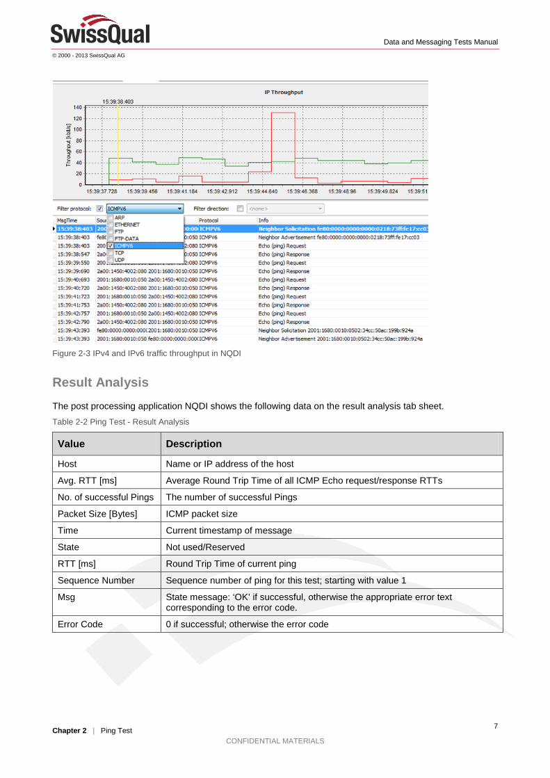
Figure 2-3 IPv4 and IPv6 traffic throughput in NQDI
Result Analysis The post processing application NQDI shows the following data on the result analysis tab sheet.
Table 2-2 Ping Test - Result Analysis
Value Description
Host Name or IP address of the host
Avg. RTT [ms] Average Round Trip Time of all ICMP Echo request/response RTTs
No. of successful Pings The number of successful Pings
Packet Size [Bytes] ICMP packet size
Time Current timestamp of message
State Not used/Reserved
RTT [ms] Round Trip Time of current ping
Sequence Number Sequence number of ping for this test; starting with value 1
Msg State message: ‘OK’ if successful, otherwise the appropriate error text corresponding to the error code.
Error Code 0 if successful; otherwise the error code
Data and Messaging Tests Manual
© 2000 - 2013 SwissQual AG
Chapter 2 | Ping Test CONFIDENTIAL MATERIALS
8
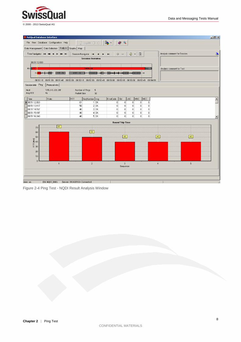
Figure 2-4 Ping Test - NQDI Result Analysis Window
Data and Messaging Tests Manual
© 2000 - 2013 SwissQual AG
Chapter 3 | Ping Trace Test CONFIDENTIAL MATERIALS
9
3 Ping Trace Test
IPv6 Support Diversity ping trace and ping tests support Internet Control Message Protocol version 6 (ICMPv6). For more information, see the "IPv6 Support" section on page 4.
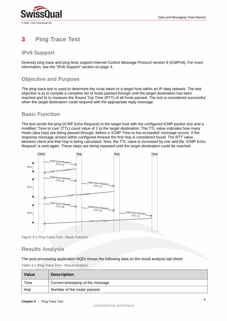
Objective and Purpose The ping trace test is used to determine the route taken to a target host within an IP data network. The test objective is a) to compile a complete list of hosts passed through until the target destination has been reached and b) to measure the Round Trip Time (RTT) of all hosts passed. The test is considered successful when the target destination could respond with the appropriate reply message.
Basic Function The test sends the ping (ICMP Echo Request) to the target host with the configured ICMP packet size and a modified ‘Time to Live’ (TTL) count value of 1 to the target destination. The TTL value indicates how many Hosts (aka Hop) are being passed through, before a ‘ICMP Time to live exceeded’ message occurs. If the response message arrived within configured timeout the first Hop is considered found. The RTT value between client and that Hop is being calculated. Now, the TTL value is increased by one and the ‘ICMP Echo Request’ is sent again. These steps are being repeated until the target destination could be reached.
ICMP Echo Request(TTL=1)
ICMP TTL ExceededRTT1
RTT2
ICMP Echo Reply
Client HostHop Hop
ICMP Echo Request(TTL=1)
ICMP Echo Request(TTL=2)
ICMP Echo Request(TTL=3)
ICMP TTL Exceeded
ICMP Echo Request(TTL=2)
ICMP Echo Request(TTL=1)
RTT3
Figure 3-1 Ping Trace Test - Basic Function
Results Analysis The post processing application NQDI shows the following data on the result analysis tab sheet: Table 3-1 Ping Trace Test - Result Analysis
Value Description
Time Current timestamp of the message
Hop Number of the router passed.
Data and Messaging Tests Manual
© 2000 - 2013 SwissQual AG
Chapter 3 | Ping Trace Test CONFIDENTIAL MATERIALS
10
Value Description
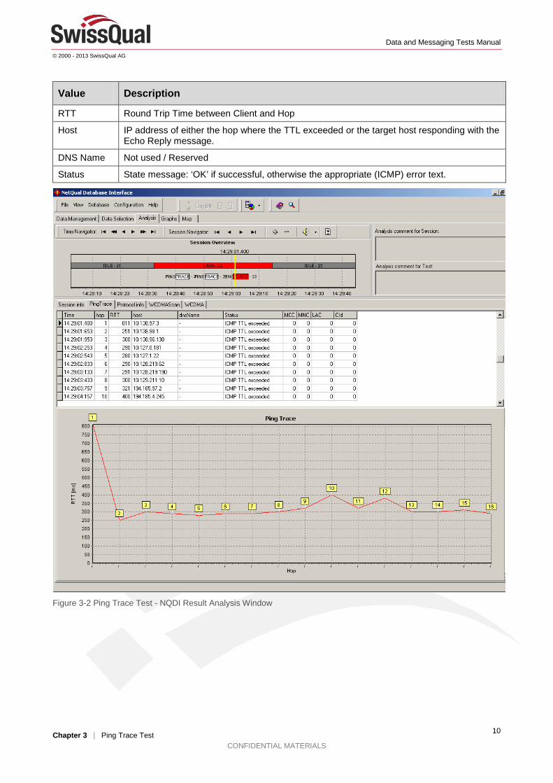
RTT Round Trip Time between Client and Hop
Host IP address of either the hop where the TTL exceeded or the target host responding with the Echo Reply message.
DNS Name Not used / Reserved
Status State message: ‘OK’ if successful, otherwise the appropriate (ICMP) error text.
Figure 3-2 Ping Trace Test - NQDI Result Analysis Window
Data and Messaging Tests Manual
© 2000 - 2013 SwissQual AG
Chapter 4 | FTP Test CONFIDENTIAL MATERIALS
11
4 FTP Test
Objective and Purpose The FTP test is used to test the FTP service availability and to measure the application throughput for file download or file upload. The test is successful when the desired operation (uploading or downloading) has succeeded.
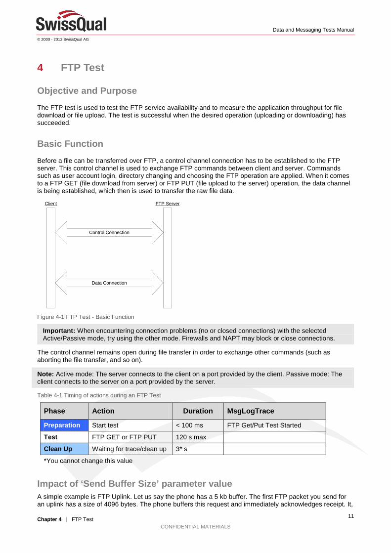
Basic Function Before a file can be transferred over FTP, a control channel connection has to be established to the FTP server. This control channel is used to exchange FTP commands between client and server. Commands such as user account login, directory changing and choosing the FTP operation are applied. When it comes to a FTP GET (file download from server) or FTP PUT (file upload to the server) operation, the data channel is being established, which then is used to transfer the raw file data.
FTP ServerClient
Control Connection
Data Connection
Figure 4-1 FTP Test - Basic Function
Important: When encountering connection problems (no or closed connections) with the selected Active/Passive mode, try using the other mode. Firewalls and NAPT may block or close connections.
The control channel remains open during file transfer in order to exchange other commands (such as aborting the file transfer, and so on).
Note: Active mode: The server connects to the client on a port provided by the client. Passive mode: The client connects to the server on a port provided by the server.
Table 4-1 Timing of actions during an FTP Test
Phase Action Duration MsgLogTrace
Preparation Start test < 100 ms FTP Get/Put Test Started
Test FTP GET or FTP PUT 120 s max
Clean Up Waiting for trace/clean up 3* s
*You cannot change this value
Impact of ‘Send Buffer Size’ parameter value A simple example is FTP Uplink. Let us say the phone has a 5 kb buffer. The first FTP packet you send for an uplink has a size of 4096 bytes. The phone buffers this request and immediately acknowledges receipt. It,
Data and Messaging Tests Manual
© 2000 - 2013 SwissQual AG
Chapter 4 | FTP Test CONFIDENTIAL MATERIALS
12
then, starts to send the info. Meanwhile, the software thinks that it just sent 4096 bytes in a fraction of a second. We have mitigated the impact of this phenomenon by averaging over several seconds, but this does not fully eliminate the impact of buffering. Besides, what we are measuring in the ftp monitor is application throughput, and this is what we are reporting.
Note: It is possible to have application throughputs exceeding the theoretical physical limitations due to enhanced phone and PC buffering techniques.
Results Analysis
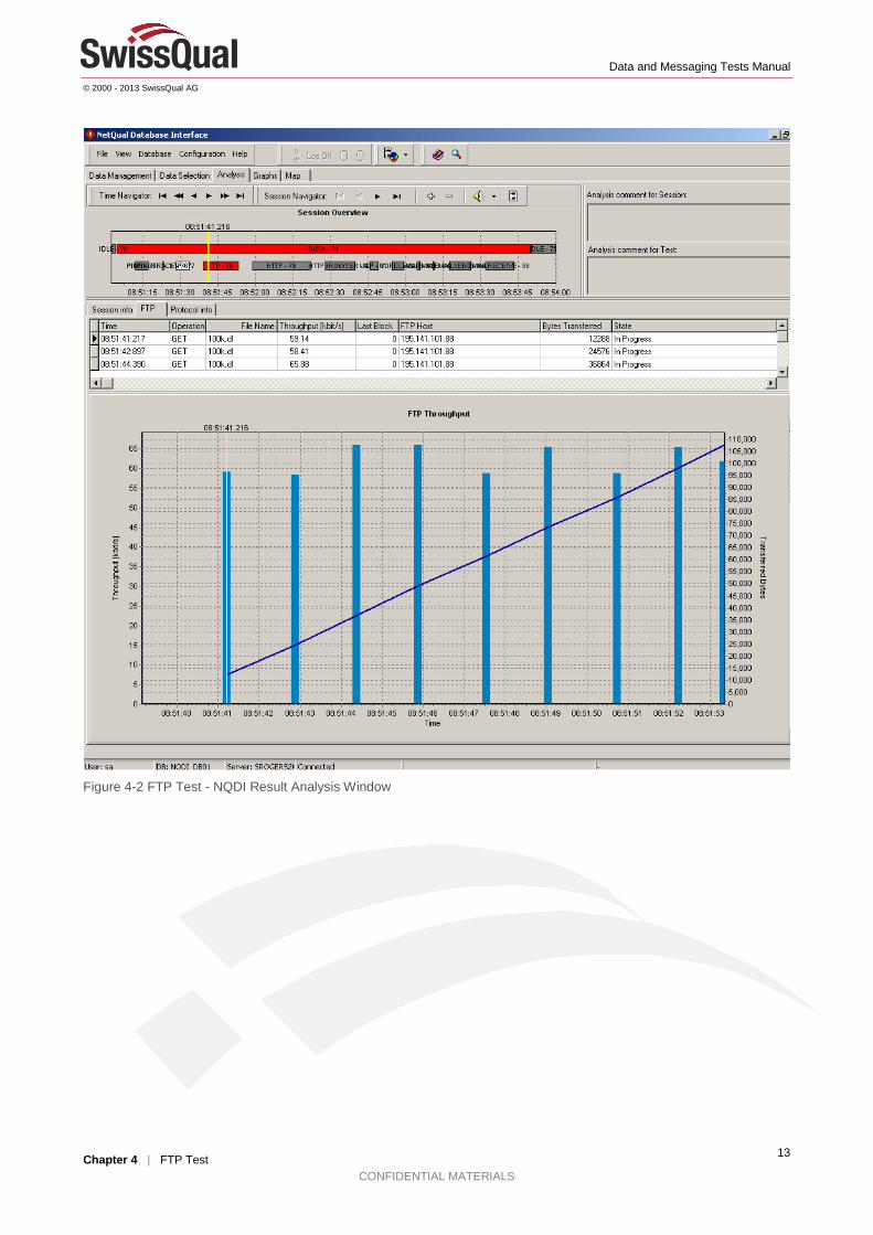
The post processing application NQDI shows the following data on the result analysis tab sheet: Table 4-2 FTP Test - Result Analysis
Value Description
Time Current timestamp of the message
Operation Operation, either PUT or GET
Filename Name of the file transferred or received
Throughput As long as the state is listed as In Progress, this value represents the intermediate throughput in bytes/s, calculated as (number of bytes transferred since last message) / (time needed). At the end of a FTP session, the state will change to Success or Failed. In case of Success, the throughput value contains the overall throughput calculated as: (total number of bytes transferred) / (total time needed). In case of Failed, the overall value not calculated
FTP Host Name or IP address of the FTP host
Bytes Transferred
Intermediate number of bytes transferred
State ‘In Progress,’ ‘Success,’ ‘Failed’
Error State message: ‘OK’ if successful, otherwise the appropriate error text corresponding to the error code.
Data and Messaging Tests Manual
© 2000 - 2013 SwissQual AG
Chapter 4 | FTP Test CONFIDENTIAL MATERIALS
13
Figure 4-2 FTP Test - NQDI Result Analysis Window
Data and Messaging Tests Manual
© 2000 - 2013 SwissQual AG
Chapter 5 | HTTP Browser Test CONFIDENTIAL MATERIALS
14
5 HTTP Browser Test
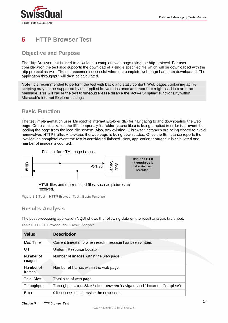
Objective and Purpose The Http Browser test is used to download a complete web page using the http protocol. For user consideration the test also supports the download of a single specified file which will be downloaded with the http protocol as well. The test becomes successful when the complete web page has been downloaded. The application throughput will then be calculated.
Note: It is recommended to perform the test with basic and static content. Web pages containing active scripting may not be supported by the applied browser instance and therefore might lead into an error message. This will cause the test to timeout! Please disable the ‘active Scripting’ functionality within Microsoft’s Internet Explorer settings.
Basic Function
The test implementation uses Microsoft’s Internet Explorer (IE) for navigating to and downloading the web page. On test initialization the IE’s temporary file folder (cache files) is being emptied in order to prevent the loading the page from the local file system. Also, any existing IE browser instances are being closed to avoid noninvolved HTTP traffic. Afterwards the web page is being downloaded. Once the IE instance reports the ‘Navigation complete’ event the test is considered finished. Now, application throughput is calculated and number of images is counted.
Figure 5-1 Test – HTTP Browser Test - Basic Function
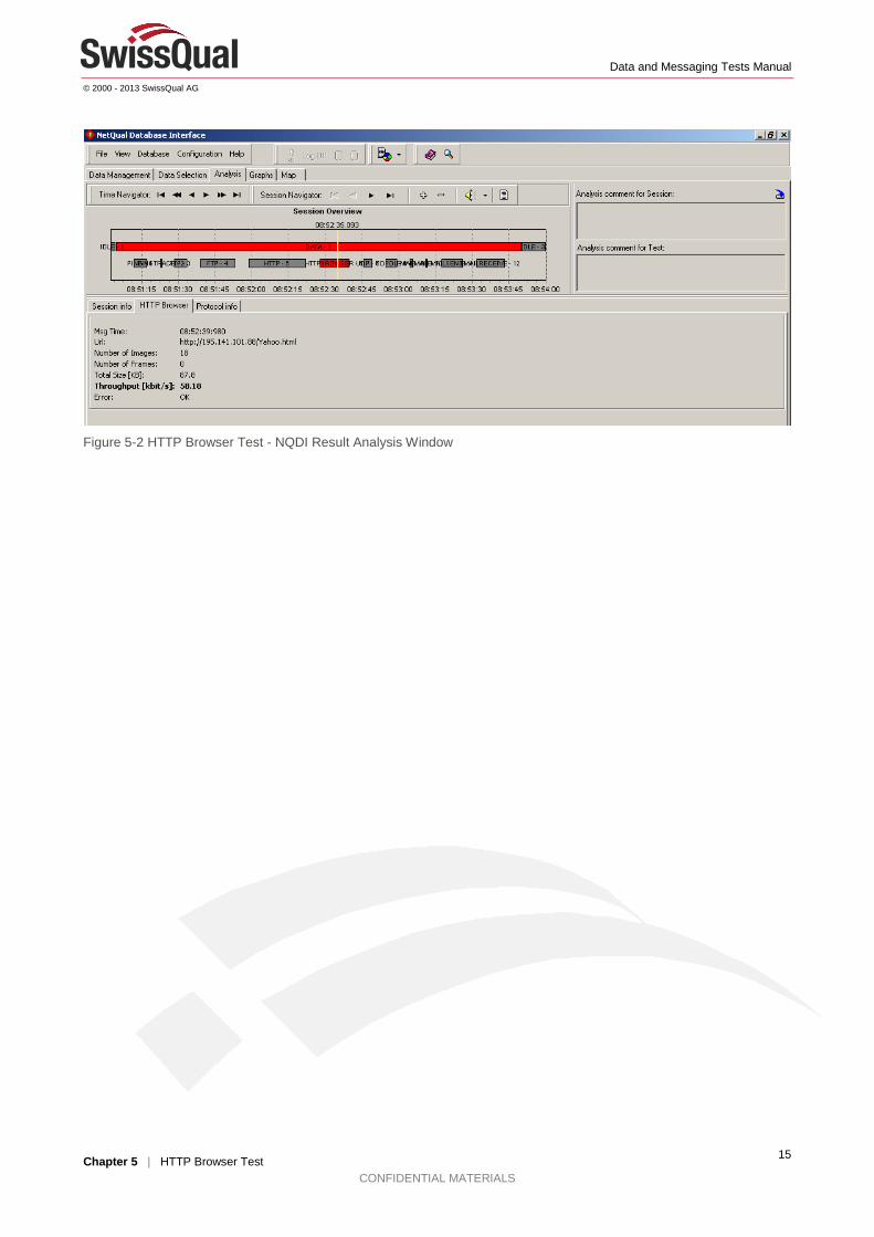
Results Analysis The post processing application NQDI shows the following data on the result analysis tab sheet:
Table 5-1 HTTP Browser Test - Result Analysis
Value Description
Msg Time Current timestamp when result message has been written.
Url Uniform Resource Locator
Number of images
Number of images within the web page.
Number of frames
Number of frames within the web page
Total Size Total size of web page.
Throughput Throughput = totalSize / (time between ‘navigate’ and ‘documentComplete’)
Error 0 if successful; otherwise the error code
HTML files and other related files, such as pictures are received.
Client
Web
Server
Request for HTML page is sent.
Time and HTTP throughput is calculated and
recorded. Port 80
Data and Messaging Tests Manual
© 2000 - 2013 SwissQual AG
Chapter 5 | HTTP Browser Test CONFIDENTIAL MATERIALS
15
Figure 5-2 HTTP Browser Test - NQDI Result Analysis Window

Data and Messaging Tests Manual
© 2000 - 2013 SwissQual AG
Chapter 6 | HTTP Transfer Test CONFIDENTIAL MATERIALS
16
6 HTTP Transfer Test
Objective and Purpose The HTTP Transfer test calculates the available throughput of an IP link. Unlike the HTTP Browser test, the HTTP Transfer test is not a service test.
The HTTP Transfer test downloads or uploads a file with the HTTP protocol and then calculates the application throughput after the file transfer is complete. The test also calculates the intermediate throughputs during the download or upload phase.
Note: Use a file of sufficient size for the IP link that you want to test.
Basic Function
Figure 6-1 Test – HTTP Transfer Test - Basic Function
Note: By default, you cannot upload any type of file to the HTTP server. Instead, you need to enable this feature for the directory on the HTTP server. You can either grant universal access to the directory or require user name and password authentication.
Table 6-1 Timing of actions during an HTTP Transfer Test
Phase Action Duration MsgLogTrace
Preparation Start test < 100 ms HTTPTransfer Get/Put Test Started
Test HTTP GET 45 s max
Clean Up Waiting for trace/clean up 3* s
*You cannot change this value
Results Analysis The post processing application NQDI shows the data in the following table on the result analysis tab sheet.
Table 6-2 HTTP Transfer Test - Result Analysis
Value Description
Msg Time Time when result message is written
Host URL or IP address of the HTTP server
Operation GET (Download) or PUT (Upload) operation
Buffer Size PUT operation uses local buffer (recommended size 32 kB)
Any file type can be transferred.
Client
Web
Server Request for HTML page is sent.
Time and HTTP throughput is calculated and
recorded Port 80

Data and Messaging Tests Manual
© 2000 - 2013 SwissQual AG
Chapter 6 | HTTP Transfer Test CONFIDENTIAL MATERIALS
17
Value Description
Local file name
PUT operation only
Remote file name
Path and file name on the HTTP server
Bytes Transferred
Intermediate number of bytes that have been transferred (“Last Block” = 0) Final file size (“Last Block” = 1)
State Possible states are: In Progress, Success, Failed
Error State message is OK if the test is successful, otherwise the error text corresponding to the error code is displayed.
Throughput As long as the state is listed as In Progress, this value represents the intermediate throughput in bytes/s, which is calculated as (number of bytes transferred since last message) / (time needed). At the end of the test, the state changes to Success or Failed. If the state is Success, the throughput value contains the overall throughput that is calculated as: (total number of bytes transferred) / (total time needed). If the state is Failed, the overall value is not calculated.
Figure 6-2 HTTP Transfer Test - NQDI Result Analysis Window

Data and Messaging Tests Manual
© 2000 - 2013 SwissQual AG
Chapter 7 | Capacity Test CONFIDENTIAL MATERIALS
18
7 Capacity Test
Objective and Purpose The Capacity test establishes multiple simultaneous peer connections for data transfer to optimize network throughput.
Round Trip Time (RTT) and TCP Receive Windows Size (RWin) define the maximum achievable throughput for a TCP/IP based connection. Modern high bandwidth networks contain diverse networking conditions and use congestion control. In such networks, the combination of RTT and RWin might not be fully optimized, which can result in suboptimal network utilization and lower throughput values than expected.
The Capacity test focuses on network stressing for the time period that you define. Typically this period lasts from 30 to 90 seconds. A successful test calculates the application throughput when the test duration elapses. A test fails if the data transfer completes before the test duration elapses or when the transfer is interrupted.
Even though each connection in the Capacity test is still limited by RTT and RWin, the sum of the multiple connections results in full network utilization.
Basic Function The test configuration requires you to define a set of HTTP URLs. The target files, which are transferred simultaneously during the test, can reside on different servers.
Important: To avoid incomplete and aborted transfers during the duration of the test, use files that are larger than 1 GB in size.
Figure 7-1 Overview of a Capacity test
An error with one or more of the simultaneous transfers results in a test failure. Similarly, if one or more of these transfers successfully completes before the test duration elapses, the test fails.
Start Data Transfer 1...n
Data Transfer 1 (e.g. http://server1.com/file1.dat)
Data Transfer 2 (e.g. http://server1.com/file1.dat)
Data Transfer n (e.g. http://server2.com/file2.dat)
Stop Data Transfer 1...n
Time
Test Duration
Data and Messaging Tests Manual
© 2000 - 2013 SwissQual AG
Chapter 7 | Capacity Test CONFIDENTIAL MATERIALS
19
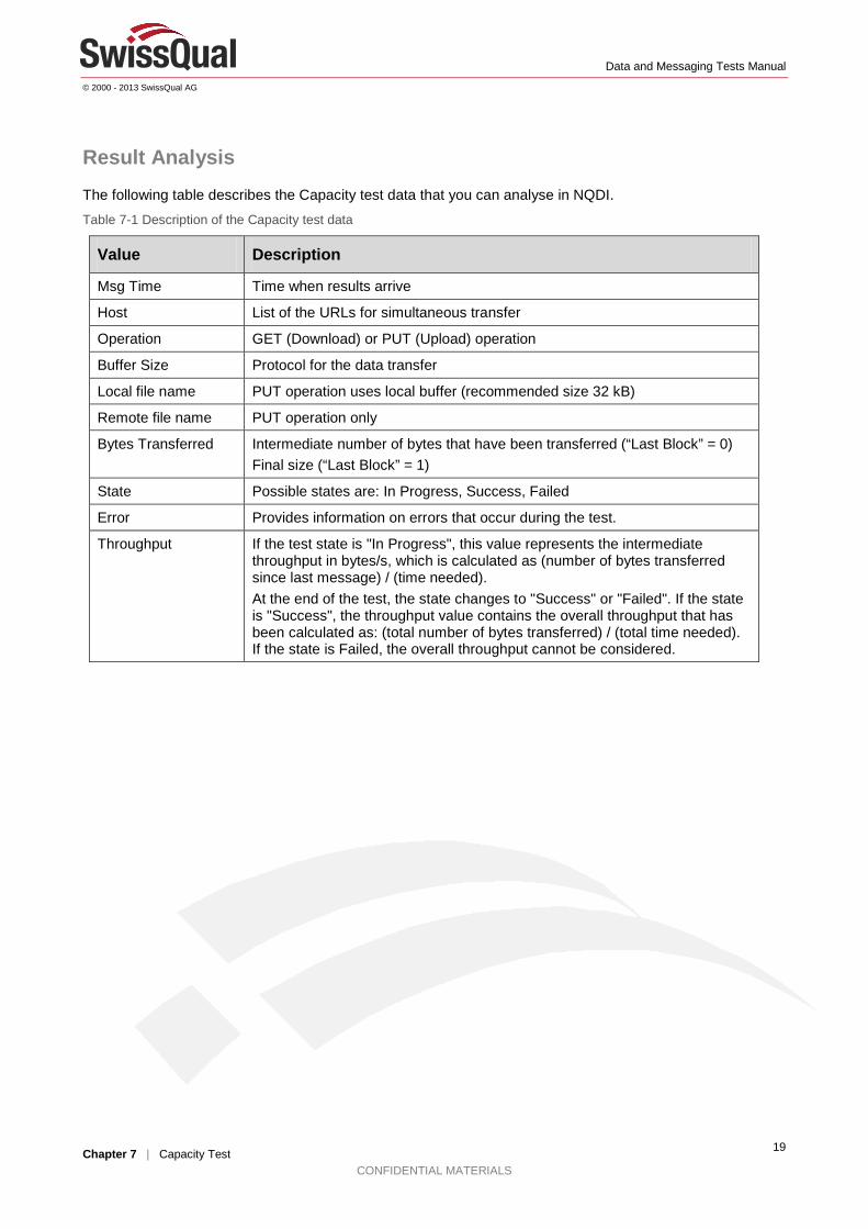
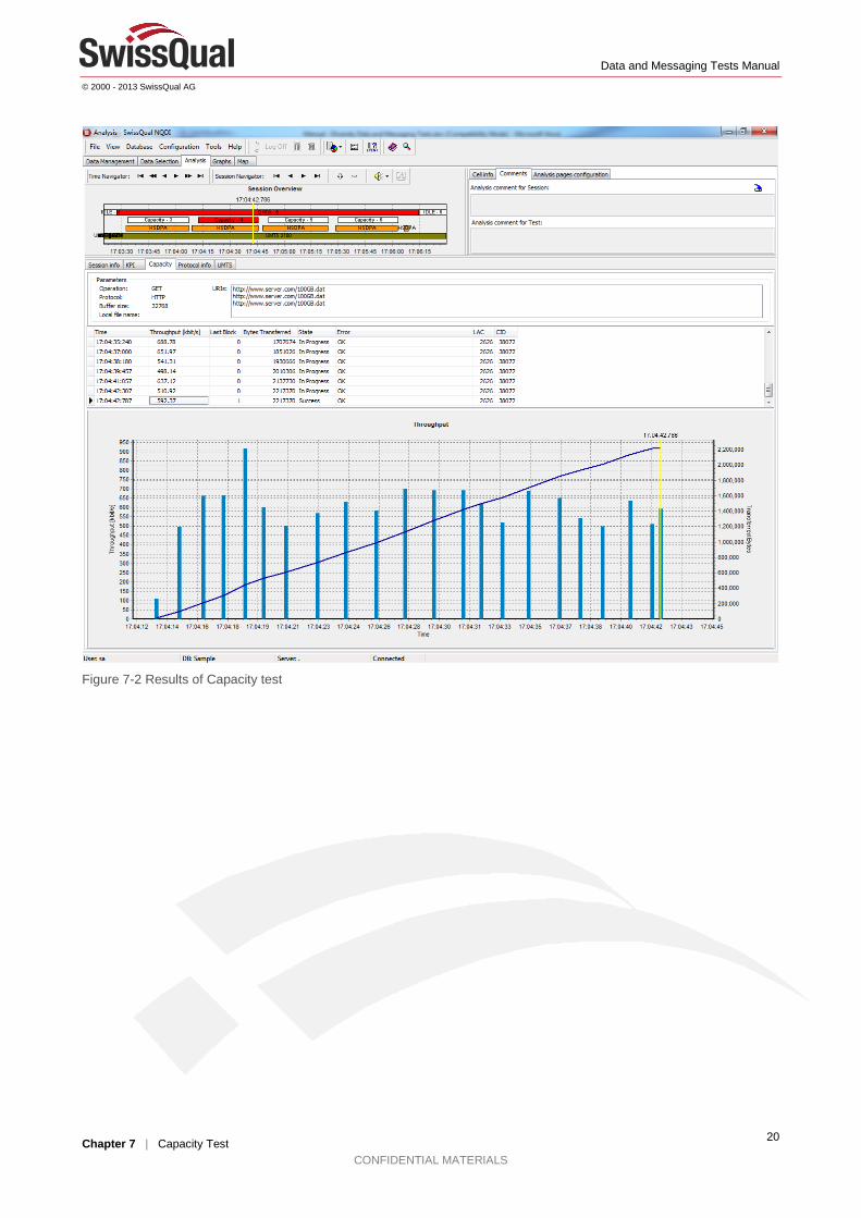
Result Analysis The following table describes the Capacity test data that you can analyse in NQDI.
Table 7-1 Description of the Capacity test data
Value Description
Msg Time Time when results arrive
Host List of the URLs for simultaneous transfer
Operation GET (Download) or PUT (Upload) operation
Buffer Size Protocol for the data transfer
Local file name PUT operation uses local buffer (recommended size 32 kB)
Remote file name PUT operation only
Bytes Transferred Intermediate number of bytes that have been transferred (“Last Block” = 0) Final size (“Last Block” = 1)
State Possible states are: In Progress, Success, Failed
Error Provides information on errors that occur during the test.
Throughput If the test state is "In Progress", this value represents the intermediate throughput in bytes/s, which is calculated as (number of bytes transferred since last message) / (time needed). At the end of the test, the state changes to "Success" or "Failed". If the state is "Success", the throughput value contains the overall throughput that has been calculated as: (total number of bytes transferred) / (total time needed). If the state is Failed, the overall throughput cannot be considered.
Data and Messaging Tests Manual
© 2000 - 2013 SwissQual AG
Chapter 7 | Capacity Test CONFIDENTIAL MATERIALS
20
Figure 7-2 Results of Capacity test
Data and Messaging Tests Manual
© 2000 - 2013 SwissQual AG
Chapter 8 | UDP Downlink Test CONFIDENTIAL MATERIALS
21
8 UDP Downlink Test
Objective and Purpose The UDP Downlink (UDP DL) test measures downlink bandwidth with a series of configurable UDP packets. The test has been introduced in order to stress the network capacity as it would be performed when running audio/visual streaming content.
Unlike other data tests, which work with any appropriate host, providing the corresponding service, such as web/http; email; …, the UDP downlink test requires a special server application. That application has to be installed and start upped beforehand. Once running, the configuration of the server application is being configured during test initialization phase.
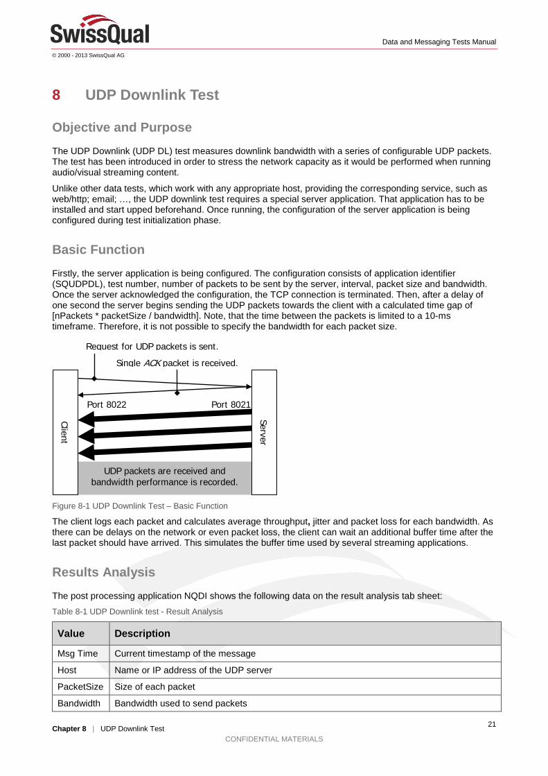
Basic Function Firstly, the server application is being configured. The configuration consists of application identifier (SQUDPDL), test number, number of packets to be sent by the server, interval, packet size and bandwidth. Once the server acknowledged the configuration, the TCP connection is terminated. Then, after a delay of one second the server begins sending the UDP packets towards the client with a calculated time gap of [nPackets * packetSize / bandwidth]. Note, that the time between the packets is limited to a 10-ms timeframe. Therefore, it is not possible to specify the bandwidth for each packet size.
Figure 8-1 UDP Downlink Test – Basic Function
The client logs each packet and calculates average throughput, jitter and packet loss for each bandwidth. As there can be delays on the network or even packet loss, the client can wait an additional buffer time after the last packet should have arrived. This simulates the buffer time used by several streaming applications.
Results Analysis The post processing application NQDI shows the following data on the result analysis tab sheet:
Table 8-1 UDP Downlink test - Result Analysis
Value Description
Msg Time Current timestamp of the message
Host Name or IP address of the UDP server
PacketSize Size of each packet
Bandwidth Bandwidth used to send packets
UDP packets are received and bandwidth performance is recorded.
Port 8022 Port 8021
Client
Server
Request for UDP packets is sent.
Single ACK packet is received.
Data and Messaging Tests Manual
© 2000 - 2013 SwissQual AG
Chapter 8 | UDP Downlink Test CONFIDENTIAL MATERIALS
22
Value Description
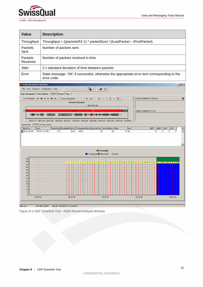
Throughput Throughput = ((packetsRX-1) * packetSize) / (tLastPacket – tFirstPacket)
Packets Sent
Number of packets sent
Packets Received
Number of packets received in time
Jitter 2 x standard deviation of time between packets
Error State message: ‘OK’ if successful, otherwise the appropriate error text corresponding to the error code.
Figure 8-2 UDP Downlink Test - NQDI Result Analysis Window
Data and Messaging Tests Manual
© 2000 - 2013 SwissQual AG
Chapter 9 | UDP Plus Test CONFIDENTIAL MATERIALS
23
9 UDP Plus Test
Objective and Purpose The UDP test measures round-trip time and throughput by round-tripping UDP packets. Both round-trip time and throughput are recorded.
UDPPlus is a more flexible, yet complex, UDP test where UDP traffic may be predefined within a chirp file. Additionally to the definitions within the chirp file, several packet size adjustment parameters can be set in order to allow high flexible test cases.
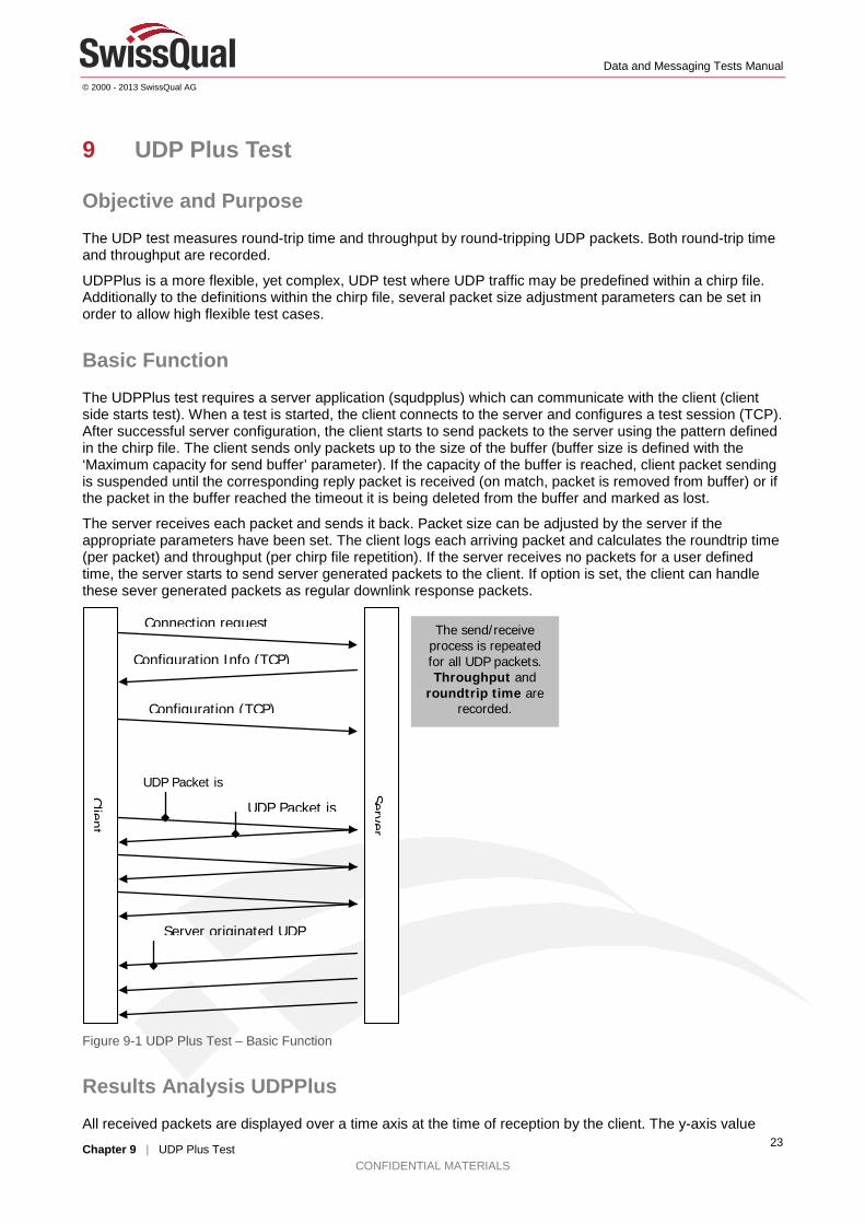
Basic Function The UDPPlus test requires a server application (squdpplus) which can communicate with the client (client side starts test). When a test is started, the client connects to the server and configures a test session (TCP). After successful server configuration, the client starts to send packets to the server using the pattern defined in the chirp file. The client sends only packets up to the size of the buffer (buffer size is defined with the ‘Maximum capacity for send buffer’ parameter). If the capacity of the buffer is reached, client packet sending is suspended until the corresponding reply packet is received (on match, packet is removed from buffer) or if the packet in the buffer reached the timeout it is being deleted from the buffer and marked as lost.
The server receives each packet and sends it back. Packet size can be adjusted by the server if the appropriate parameters have been set. The client logs each arriving packet and calculates the roundtrip time (per packet) and throughput (per chirp file repetition). If the server receives no packets for a user defined time, the server starts to send server generated packets to the client. If option is set, the client can handle these sever generated packets as regular downlink response packets.
Figure 9-1 UDP Plus Test – Basic Function
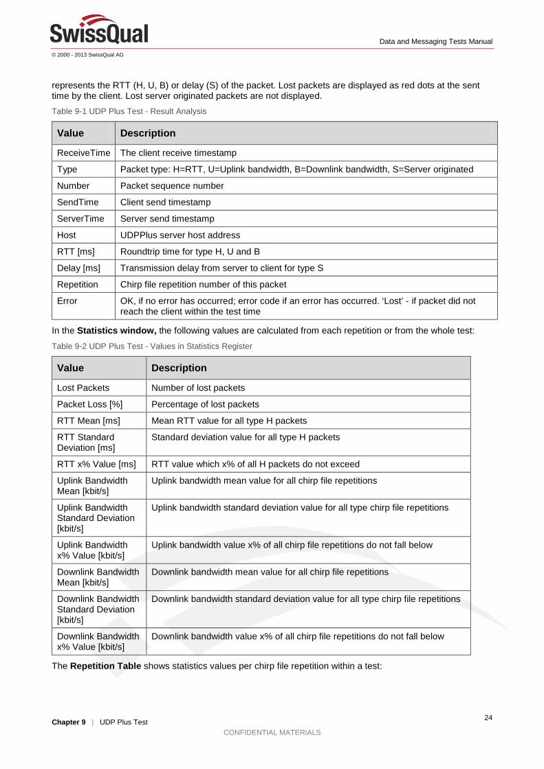
Results Analysis UDPPlus All received packets are displayed over a time axis at the time of reception by the client. The y-axis value
Client
Server
UDP Packet is
The send/receive process is repeated for all UDP packets. Throughput and
roundtrip time are recorded.
UDP Packet is
Connection request
Configuration Info (TCP)
Server originated UDP
Configuration (TCP)
Data and Messaging Tests Manual
© 2000 - 2013 SwissQual AG
Chapter 9 | UDP Plus Test CONFIDENTIAL MATERIALS
24
represents the RTT (H, U, B) or delay (S) of the packet. Lost packets are displayed as red dots at the sent time by the client. Lost server originated packets are not displayed. Table 9-1 UDP Plus Test - Result Analysis
Value Description
ReceiveTime The client receive timestamp
Type Packet type: H=RTT, U=Uplink bandwidth, B=Downlink bandwidth, S=Server originated
Number Packet sequence number
SendTime Client send timestamp
ServerTime Server send timestamp
Host UDPPlus server host address
RTT [ms] Roundtrip time for type H, U and B
Delay [ms] Transmission delay from server to client for type S
Repetition Chirp file repetition number of this packet
Error OK, if no error has occurred; error code if an error has occurred. ‘Lost’ - if packet did not reach the client within the test time
In the Statistics window, the following values are calculated from each repetition or from the whole test:
Table 9-2 UDP Plus Test - Values in Statistics Register
Value Description
Lost Packets Number of lost packets
Packet Loss [%] Percentage of lost packets
RTT Mean [ms] Mean RTT value for all type H packets
RTT Standard Deviation [ms]
Standard deviation value for all type H packets
RTT x% Value [ms] RTT value which x% of all H packets do not exceed
Uplink Bandwidth Mean [kbit/s]
Uplink bandwidth mean value for all chirp file repetitions
Uplink Bandwidth Standard Deviation [kbit/s]
Uplink bandwidth standard deviation value for all type chirp file repetitions
Uplink Bandwidth x% Value [kbit/s]
Uplink bandwidth value x% of all chirp file repetitions do not fall below
Downlink Bandwidth Mean [kbit/s]
Downlink bandwidth mean value for all chirp file repetitions
Downlink Bandwidth Standard Deviation [kbit/s]
Downlink bandwidth standard deviation value for all type chirp file repetitions
Downlink Bandwidth x% Value [kbit/s]
Downlink bandwidth value x% of all chirp file repetitions do not fall below
The Repetition Table shows statistics values per chirp file repetition within a test:
Data and Messaging Tests Manual
© 2000 - 2013 SwissQual AG
Chapter 9 | UDP Plus Test CONFIDENTIAL MATERIALS
25
Table 9-3 UDP Plus test - Statistics in Repetition Table
Repetition Number of this repetition
RTT Mean [ms] Mean RTT value for all type H packets of this repetition
RTT Std Dev [ms] Standard deviation value for all type H packets of this repetition
RTT x% Val [ms] RTT value which x% of all H packets of this repetition do not exceed
ULBandwidth [kbit/s] Uplink bandwidth value of this repetition
DLBandwidth [kbit/s] Downlink bandwidth value of this repetition
Lost Packets Lost packets value of this repetition
Figure 9-2 UDP Plus Test - NQDI Result Analysis Window
Data and Messaging Tests Manual
© 2000 - 2013 SwissQual AG
Chapter 10 | Email Send Test CONFIDENTIAL MATERIALS
26
10 Email Send Test
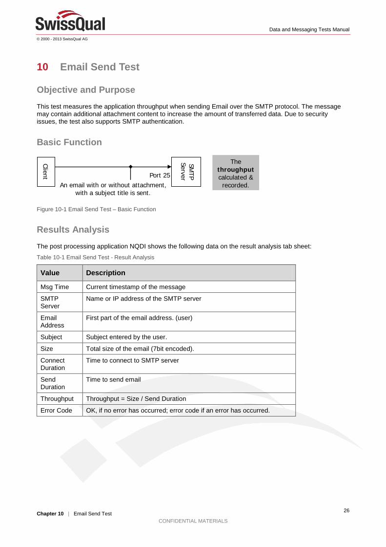
Objective and Purpose This test measures the application throughput when sending Email over the SMTP protocol. The message may contain additional attachment content to increase the amount of transferred data. Due to security issues, the test also supports SMTP authentication.
Basic Function
Figure 10-1 Email Send Test – Basic Function
Results Analysis The post processing application NQDI shows the following data on the result analysis tab sheet:
Table 10-1 Email Send Test - Result Analysis
Value Description
Msg Time Current timestamp of the message
SMTP Server
Name or IP address of the SMTP server
Email Address
First part of the email address. (user)
Subject Subject entered by the user.
Size Total size of the email (7bit encoded).
Connect Duration
Time to connect to SMTP server
Send Duration
Time to send email
Throughput Throughput = Size / Send Duration
Error Code OK, if no error has occurred; error code if an error has occurred.
Client
SMTP
Server
The throughput calculated & recorded. An email with or without attachment,
with a subject title is sent.
Port 25

Data and Messaging Tests Manual
© 2000 - 2013 SwissQual AG
Chapter 10 | Email Send Test CONFIDENTIAL MATERIALS
27
Figure 10-2 Email Send Test - NQDI Result Analysis Window
Data and Messaging Tests Manual
© 2000 - 2013 SwissQual AG
Chapter 11 | Email Receive Test CONFIDENTIAL MATERIALS
28
11 Email Receive Test
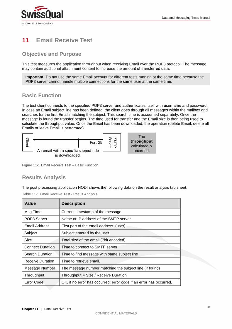
Objective and Purpose This test measures the application throughput when receiving Email over the POP3 protocol. The message may contain additional attachment content to increase the amount of transferred data.
Important: Do not use the same Email account for different tests running at the same time because the POP3 server cannot handle multiple connections for the same user at the same time.
Basic Function The test client connects to the specified POP3 server and authenticates itself with username and password. In case an Email subject line has been defined, the client goes through all messages within the mailbox and searches for the first Email matching the subject. This search time is accounted separately. Once the message is found the transfer begins. The time used for transfer and the Email size is then being used to calculate the throughput value. Once the Email has been downloaded, the operation (delete Email; delete all Emails or leave Email is performed).
Figure 11-1 Email Receive Test – Basic Function
Results Analysis The post processing application NQDI shows the following data on the result analysis tab sheet:
Table 11-1 Email Receive Test - Result Analysis
Value Description
Msg Time Current timestamp of the message
POP3 Server Name or IP address of the SMTP server
Email Address First part of the email address. (user)
Subject Subject entered by the user.
Size Total size of the email (7bit encoded).
Connect Duration Time to connect to SMTP server
Search Duration Time to find message with same subject line
Receive Duration Time to retrieve email.
Message Number The message number matching the subject line (if found)
Throughput Throughput = Size / Receive Duration
Error Code OK, if no error has occurred; error code if an error has occurred.
Client
SMTP
Server
The throughput calculated & recorded. An email with a specific subject title
is downloaded.
Port 25
Data and Messaging Tests Manual
© 2000 - 2013 SwissQual AG
Chapter 11 | Email Receive Test CONFIDENTIAL MATERIALS
29
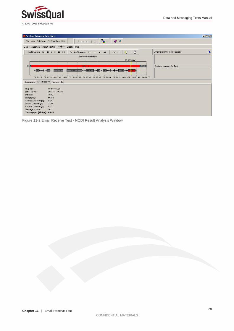
Figure 11-2 Email Receive Test - NQDI Result Analysis Window
Data and Messaging Tests Manual
© 2000 - 2013 SwissQual AG
Chapter 12 | GPRS Attach Test CONFIDENTIAL MATERIALS
30
12 GPRS Attach Test
Objective and Purpose The objective of this test is to perform a successful GPRS attach to the mobile network. The test is successful if attaching to the network succeeded. As result parameter the duration for attaching the device is being reported. Note that this test is for mobile communication network devices only.
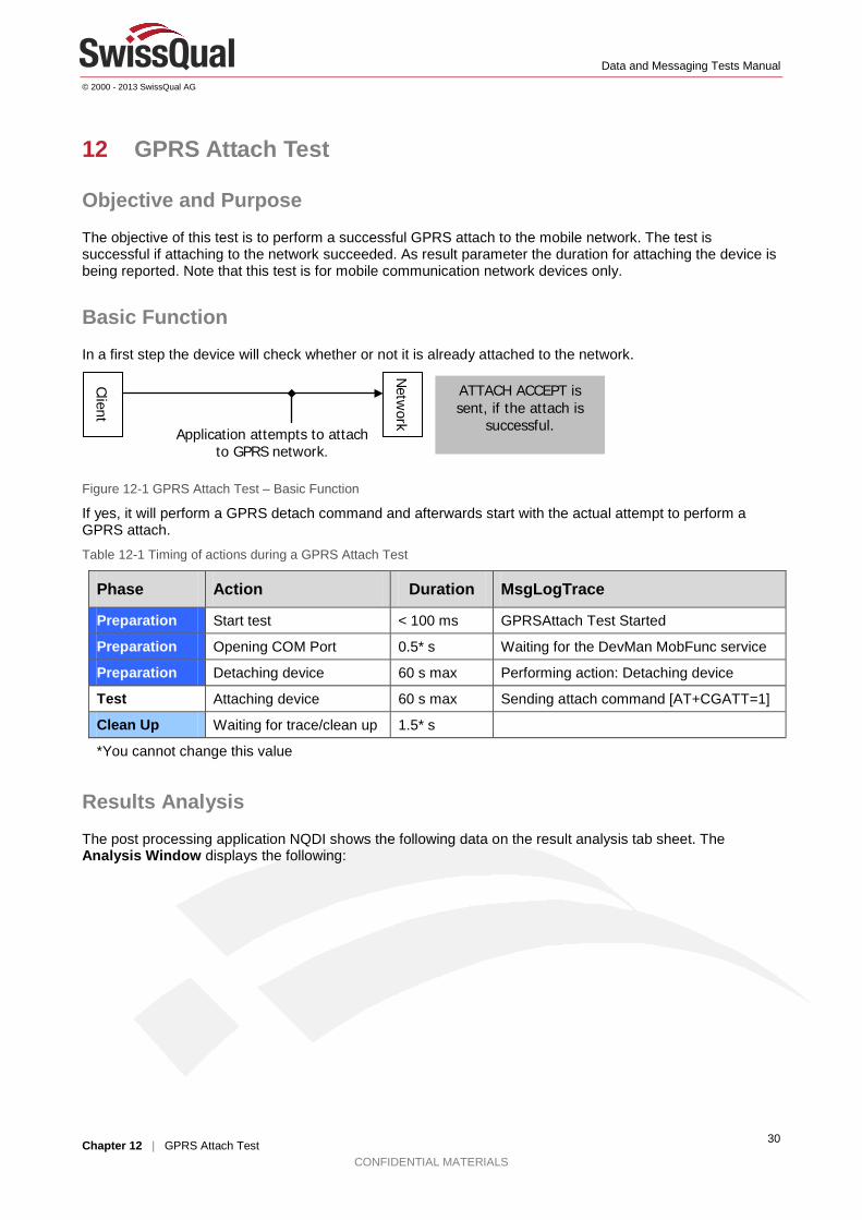
Basic Function In a first step the device will check whether or not it is already attached to the network.
Figure 12-1 GPRS Attach Test – Basic Function
If yes, it will perform a GPRS detach command and afterwards start with the actual attempt to perform a GPRS attach.
Table 12-1 Timing of actions during a GPRS Attach Test
Phase Action Duration MsgLogTrace
Preparation Start test < 100 ms GPRSAttach Test Started
Preparation Opening COM Port 0.5* s Waiting for the DevMan MobFunc service
Preparation Detaching device 60 s max Performing action: Detaching device
Test Attaching device 60 s max Sending attach command [AT+CGATT=1]
Clean Up Waiting for trace/clean up 1.5* s
*You cannot change this value
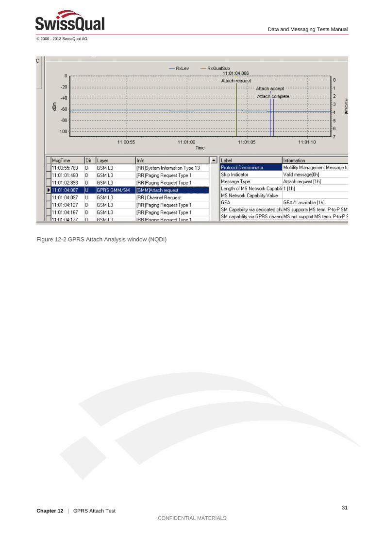
Results Analysis The post processing application NQDI shows the following data on the result analysis tab sheet. The Analysis Window displays the following:
Client
Netw
ork Application attempts to attach to GPRS network.
ATTACH ACCEPT is sent, if the attach is
successful.
Data and Messaging Tests Manual
© 2000 - 2013 SwissQual AG
Chapter 12 | GPRS Attach Test CONFIDENTIAL MATERIALS
31
Figure 12-2 GPRS Attach Analysis window (NQDI)
Data and Messaging Tests Manual
© 2000 - 2013 SwissQual AG
Chapter 13 | GPRS Detach Test CONFIDENTIAL MATERIALS
32
13 GPRS Detach Test
Objective and Purpose The objective of this test is to perform a successful GPRS detach to the mobile network. The test is successful if detaching to the network succeeded. In case the device is already detached, the test is successful as well, even though, no active operation took place. As result parameter the duration for detaching the device is being reported. Note that this test is for mobile communication network devices only.
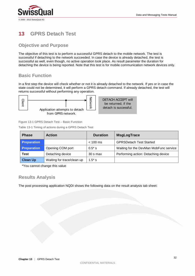
Basic Function In a first step the device will check whether or not it is already detached to the network. If yes or in case the state could not be determined, it will perform a GPRS detach command. If already detached, the test will returns successful without performing any operation.
Figure 13-1 GPRS Detach Test – Basic Function
Table 13-1 Timing of actions during a GPRS Detach Test
Phase Action Duration MsgLogTrace
Preparation < 100 ms GPRSDetach Test Started
Preparation Opening COM port 0.5* s Waiting for the DevMan MobFunc service
Test Detaching device 30 s max Performing action: Detaching device
Clean Up Waiting for trace/clean up 1.5* s
*You cannot change this value
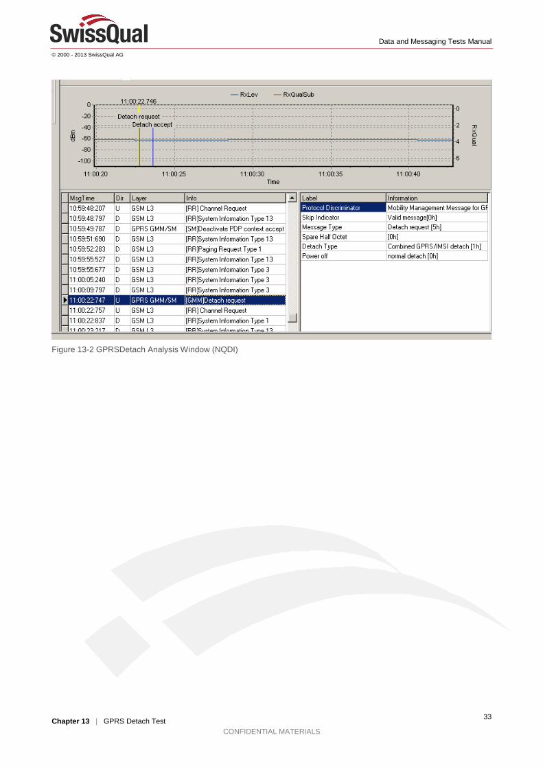
Results Analysis
The post processing application NQDI shows the following data on the result analysis tab sheet:
Client
Netw
ork Application attempts to detach from GPRS network.
DETACH ACCEPT will be returned, if the
detach is successful.
Data and Messaging Tests Manual
© 2000 - 2013 SwissQual AG
Chapter 13 | GPRS Detach Test CONFIDENTIAL MATERIALS
33
Figure 13-2 GPRSDetach Analysis Window (NQDI)
Data and Messaging Tests Manual
© 2000 - 2013 SwissQual AG
Chapter 14 | PDP Activation Test CONFIDENTIAL MATERIALS
34
14 PDP Activation Test
Objective and Purpose The PDP Activation test tries to activate the PDP context. The test is successful when the device could successfully connect to the mobile network. Note that this test can only be performed with mobile communication network devices.
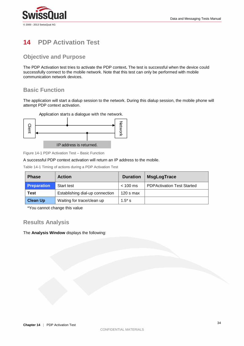
Basic Function The application will start a dialup session to the network. During this dialup session, the mobile phone will attempt PDP context activation.
Figure 14-1 PDP Activation Test – Basic Function
A successful PDP context activation will return an IP address to the mobile.
Table 14-1 Timing of actions during a PDP Activation Test
Phase Action Duration MsgLogTrace
Preparation Start test < 100 ms PDPActivation Test Started
Test Establishing dial-up connection 120 s max
Clean Up Waiting for trace/clean up 1.5* s
*You cannot change this value
Results Analysis The Analysis Window displays the following:
Client
Netw
ork
Application starts a dialogue with the network.
IP address is returned.

Data and Messaging Tests Manual
© 2000 - 2013 SwissQual AG
Chapter 14 | PDP Activation Test CONFIDENTIAL MATERIALS
35
Figure 14-2 PDP Activation Test - NQDI Result Analysis Window
Data and Messaging Tests Manual
© 2000 - 2013 SwissQual AG
Chapter 15 | PDP Deactivation Test CONFIDENTIAL MATERIALS
36
15 PDP Deactivation Test
Objective and Purpose The PDP Deactivation test tries to deactivate the PDP context. The test is successful when the device could successfully disconnect from the mobile network. Note that this test can only be performed with mobile communication network devices.
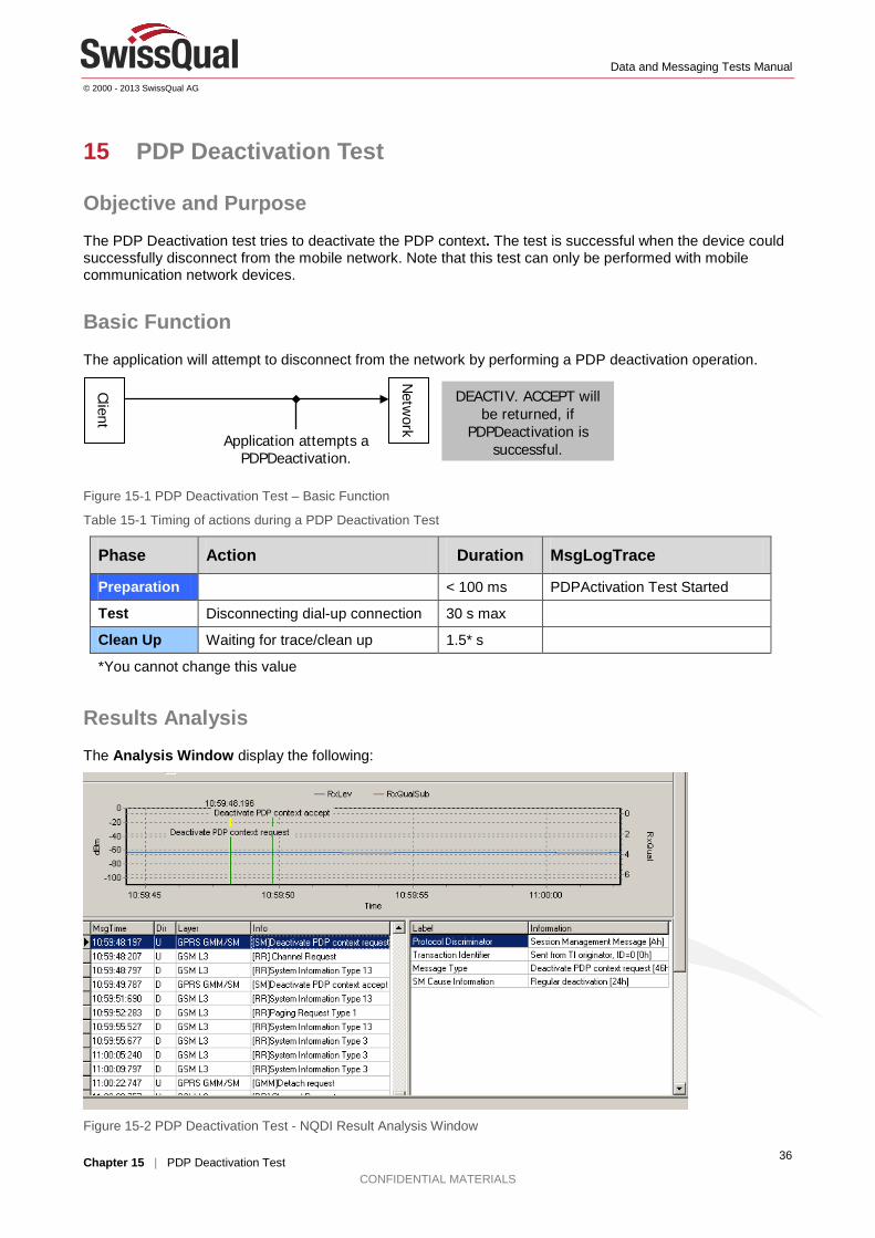
Basic Function The application will attempt to disconnect from the network by performing a PDP deactivation operation.
Figure 15-1 PDP Deactivation Test – Basic Function
Table 15-1 Timing of actions during a PDP Deactivation Test
Phase Action Duration MsgLogTrace
Preparation < 100 ms PDPActivation Test Started
Test Disconnecting dial-up connection 30 s max
Clean Up Waiting for trace/clean up 1.5* s
*You cannot change this value
Results Analysis The Analysis Window display the following:
Figure 15-2 PDP Deactivation Test - NQDI Result Analysis Window
Client
Netw
ork Application attempts a PDPDeactivation.
DEACTIV. ACCEPT will be returned, if
PDPDeactivation is successful.
Data and Messaging Tests Manual
© 2000 - 2013 SwissQual AG
Chapter 16 | WAP Test CONFIDENTIAL MATERIALS
37
16 WAP Test
Objective and Purpose The Wireless Application Protocol (WAP) test intends to measure the performance of the WAP service by downloading a web page with the WAP protocol. Procedure and result calculation is similar to the HTTP Browser test: Application throughput is calculated as well as the numbers of images embedded within the web page are counted. The test is successful when the complete web page could be downloaded.
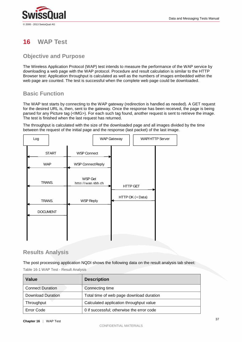
Basic Function The WAP test starts by connecting to the WAP gateway (redirection is handled as needed). A GET request for the desired URL is, then, sent to the gateway. Once the response has been received, the page is being parsed for any Picture tag (<IMG>). For each such tag found, another request is sent to retrieve the image. The test is finished when the last request has returned.
The throughput is calculated with the size of the downloaded page and all images divided by the time between the request of the initial page and the response (last packet) of the last image.
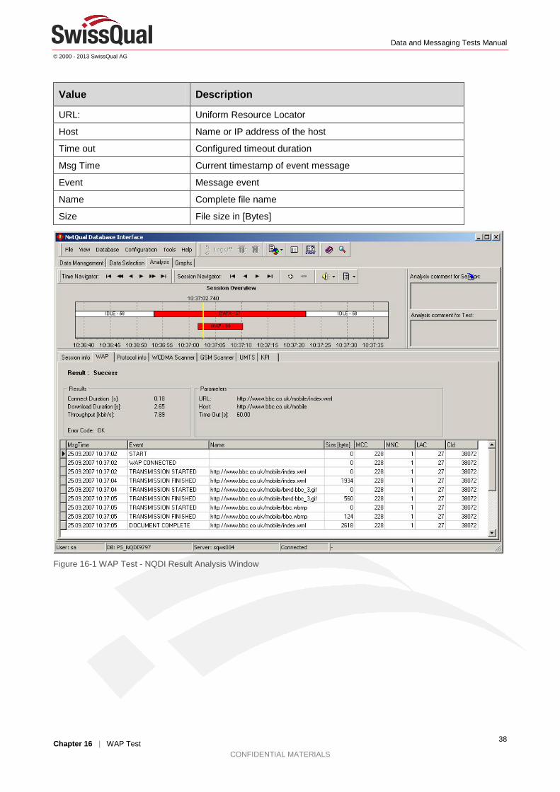
Results Analysis
The post processing application NQDI shows the following data on the result analysis tab sheet: Table 16-1 WAP Test - Result Analysis
Value Description
Connect Duration Connecting time
Download Duration Total time of web page download duration
Throughput Calculated application throughput value
Error Code 0 if successful; otherwise the error code
WAP Gateway
WAP/HTTP Server
WSP Connect
WSP ConnectReply
WSP Get http://wap.sbb.ch
HTTP GET
HTTP OK (+Data) WSP Reply
Log
START
WAP
TRANS.
TRANS.
DOCUMENT
Data and Messaging Tests Manual
© 2000 - 2013 SwissQual AG
Chapter 16 | WAP Test CONFIDENTIAL MATERIALS
38
Value Description
URL: Uniform Resource Locator
Host Name or IP address of the host
Time out Configured timeout duration
Msg Time Current timestamp of event message
Event Message event
Name Complete file name
Size File size in [Bytes]
Figure 16-1 WAP Test - NQDI Result Analysis Window

Data and Messaging Tests Manual
© 2000 - 2013 SwissQual AG
Chapter 17 | SMS Send Test CONFIDENTIAL MATERIALS
39
17 SMS Send Test
Objective and Purpose The SMS Send test sends a message text by using the Short Message Service (SMS). Receiver of the SMS is often another mobile device providing SMS Receiving capabilities. This test can be used as a send only test (Single Ended) or in conjunction with Diversity receiver device (B-side). The test objective is to test the SMS service by successfully sending a short text message to a receiver number.
Important: SMS Send test cannot be mixed with other data tests!
Basic Function The message text consists of auto created identifiers and random or user defined text data which can be used by an optional receiver for proper SMS identification. Once the SMS is constructed, it is being sent to the configured SMSC.
Figure 17-1 SMSSend Test Diagram
Results Analysis The post processing application NQDI shows the following data on the result analysis tab sheet:
Figure 17-2 SMS Send test - Result Analysis Window
Client
Receiver Application attempts to
send SMS
Status Report will indicate success or
failure.

Data and Messaging Tests Manual
© 2000 - 2013 SwissQual AG
Chapter 17 | SMS Send Test CONFIDENTIAL MATERIALS
40
Table 17-1 SMS Send Test - Result Analysis
Value Description
Send Duration Time to send the text message
End-To-End Delivery Time Duration between sending and receiving a message (Not used in SMS send only tests)
SMS Size Number of characters within the text message
Max Send Time Timeout value for sending the message
Pause Time Sender Time between sending of two messages
Sender Number Phone number of sender (Not used in SMS send only tests)
Receiver Number Phone number of receiver
Error Code State message: ‘OK’ if successful, otherwise the appropriate error text corresponding to the error code.
Data and Messaging Tests Manual
© 2000 - 2013 SwissQual AG
Chapter 18 | SMS Receive Test CONFIDENTIAL MATERIALS
41
18 SMS Receive Test
Objective and Purpose The SMS Receive test waits for an incoming SMS message. Sender/Originator of the SMS is another mobile device providing SMS Sending capabilities within. This test can be used as a receive only test (Single Ended) or in conjunction with Diversity sender device. The test objective is to test the SMS service by successfully receiving a short text message.
Important: SMS Receive test cannot be mixed with other data tests! Only one test per job allowed.
Important: The incoming SMS should be computed by Diversity; otherwise the error ‘unexpected SMS received’ will occur.
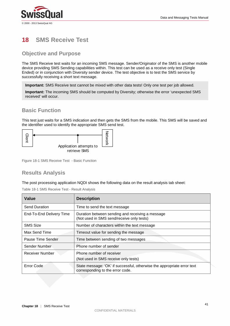
Basic Function This test just waits for a SMS indication and then gets the SMS from the mobile. This SMS will be saved and the identifier used to identify the appropriate SMS send test.
Figure 18-1 SMS Receive Test - Basic Function
Results Analysis The post processing application NQDI shows the following data on the result analysis tab sheet:
Table 18-1 SMS Receive Test - Result Analysis
Value Description
Send Duration Time to send the text message
End-To-End Delivery Time Duration between sending and receiving a message (Not used in SMS send/receive only tests)
SMS Size Number of characters within the text message
Max Send Time Timeout value for sending the message
Pause Time Sender Time between sending of two messages
Sender Number Phone number of sender
Receiver Number Phone number of receiver (Not used in SMS receive only tests)
Error Code State message: ‘OK’ if successful, otherwise the appropriate error text corresponding to the error code.
Client
Netw
ork Application attempts to retrieve SMS
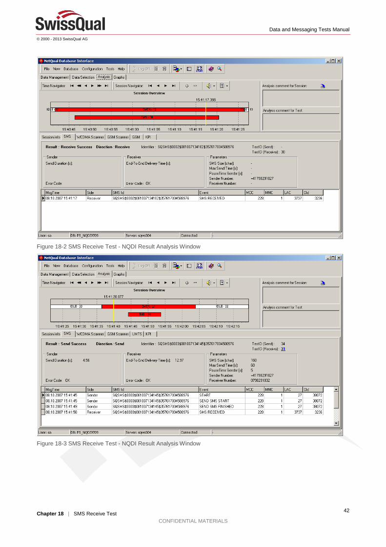
Data and Messaging Tests Manual
© 2000 - 2013 SwissQual AG
Chapter 18 | SMS Receive Test CONFIDENTIAL MATERIALS
42
Figure 18-2 SMS Receive Test - NQDI Result Analysis Window
Figure 18-3 SMS Receive Test - NQDI Result Analysis Window
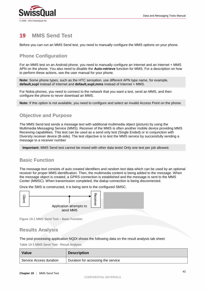
Data and Messaging Tests Manual
© 2000 - 2013 SwissQual AG
Chapter 19 | MMS Send Test CONFIDENTIAL MATERIALS
43
19 MMS Send Test Before you can run an MMS Send test, you need to manually configure the MMS options on your phone.
Phone Configuration For an MMS test on an Android phone, you need to manually configure an Internet and an Internet + MMS APN on the phone. You also need to disable the Auto-retrieve function for MMS. For a description on how to perform these actions, see the user manual for your phone.
Note: Some phone types, such as the HTC sensation, use different APN type name, for example, default,supl instead of Internet and default,supl,mms instead of Internet + MMS.
For Nokia phones, you need to connect to the network that you want a test, send an MMS, and then configure the phone to never download an MMS.
Note: If this option is not available, you need to configure and select an invalid Access Point on the phone.
Objective and Purpose The MMS Send test sends a message text with additional multimedia object (picture) by using the Multimedia Messaging Service (MMS). Receiver of the MMS is often another mobile device providing MMS Receiving capabilities. This test can be used as a send only test (Single Ended) or in conjunction with Diversity receiver device (B-side). The test objective is to test the MMS service by successfully sending a message to a receiver number
Important: MMS Send test cannot be mixed with other data tests! Only one test per job allowed.
Basic Function The message text consists of auto created identifiers and random text data which can be used by an optional receiver for proper MMS identification. Then, the multimedia content is being added to the message. When the message object is created, a GPRS connection is established and the message is sent to the MMS Center (MMSC). When transmission completed, the dialup connection is being disconnected.
Once the SMS is constructed, it is being sent to the configured SMSC.
Figure 19-1 MMS Send Test – Basic Function
Results Analysis The post processing application NQDI shows the following data on the result analysis tab sheet:
Table 19-1 MMS Send Test - Result Analysis
Value Description
Service Access duration Duration for accessing the service
Client
Receiver Application attempts to
send MMS
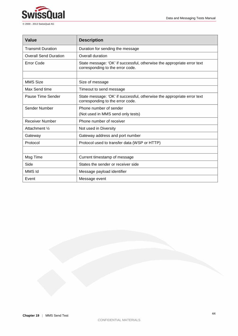
Data and Messaging Tests Manual
© 2000 - 2013 SwissQual AG
Chapter 19 | MMS Send Test CONFIDENTIAL MATERIALS
44
Value Description
Transmit Duration Duration for sending the message
Overall Send Duration Overall duration
Error Code State message: ‘OK’ if successful, otherwise the appropriate error text corresponding to the error code.
MMS Size Size of message
Max Send time Timeout to send message
Pause Time Sender State message: ‘OK’ if successful, otherwise the appropriate error text corresponding to the error code.
Sender Number Phone number of sender (Not used in MMS send only tests)
Receiver Number Phone number of receiver
Attachment ½ Not used in Diversity
Gateway Gateway address and port number
Protocol Protocol used to transfer data (WSP or HTTP)
Msg Time Current timestamp of message
Side States the sender or receiver side
MMS Id Message payload identifier
Event Message event
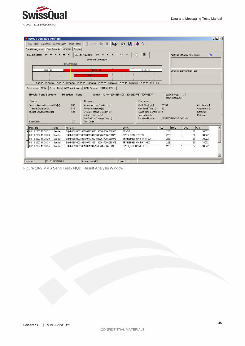
Data and Messaging Tests Manual
© 2000 - 2013 SwissQual AG
Chapter 19 | MMS Send Test CONFIDENTIAL MATERIALS
45
Figure 19-2 MMS Send Test - NQDI Result Analysis Window
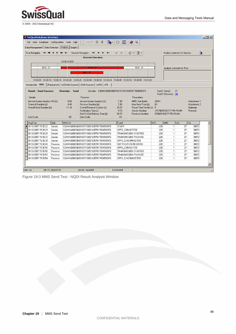
Data and Messaging Tests Manual
© 2000 - 2013 SwissQual AG
Chapter 19 | MMS Send Test CONFIDENTIAL MATERIALS
46
Figure 19-3 MMS Send Test - NQDI Result Analysis Window
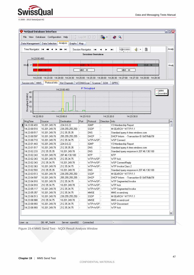
Data and Messaging Tests Manual
© 2000 - 2013 SwissQual AG
Chapter 19 | MMS Send Test CONFIDENTIAL MATERIALS
47
Figure 19-4 MMS Send Test - NQDI Result Analysis Window
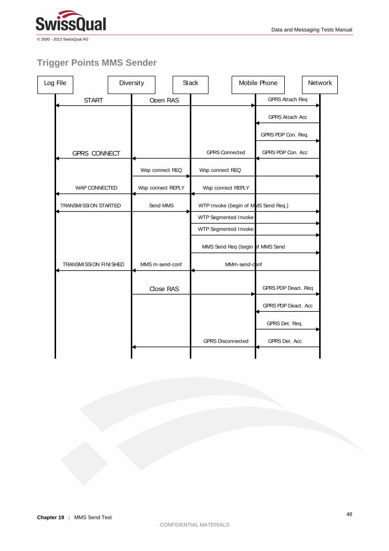
Data and Messaging Tests Manual
© 2000 - 2013 SwissQual AG
Chapter 19 | MMS Send Test CONFIDENTIAL MATERIALS
48
Trigger Points MMS Sender
Log File Diversity Mobile Phone Network Stack
Open RAS GPRS Attach Req
GPRS Attach Acc
START
GPRS PDP Con. Req.
GPRS PDP Con. Acc GPRS_CONNECT
GPRS Connected
Wsp connect REQ Wsp connect REQ
Wsp connect REPLY Wsp connect REPLY WAP CONNECTED
WTP Invoke (begin of MMS Send Req.) Send MMS TRANSMISSION STARTED
WTP Segmented Invoke
WTP Segmented Invoke
MMS Send Req (begin of MMS Send
MMm-send-conf MMS m-send-conf TRANSMISSION FINISHED
Close RAS GPRS PDP Deact. Req
GPRS PDP Deact. Acc
GPRS Det. Req.
GPRS Det. Acc GPRS Disconnected

Data and Messaging Tests Manual
© 2000 - 2013 SwissQual AG
Chapter 20 | MMS Receive Test CONFIDENTIAL MATERIALS
49
20 MMS Receive Test Before you can run an MMS Send test, you need to manually configure the MMS options on your phone. For more information, see the "Phone Configuration" section on page 43.
Objective and Purpose
Important: MMS Receive test cannot be mixed with other data tests. Only one test per job allowed. The incoming MMS should be computed by Diversity; otherwise the error ‘unexpected SMS received’ will occur.
The MMS Receive test attempts to retrieve a MMS message from the network.
Basic Function This test, first, waits for an MMS notification indication sent via (usually two) SMS. Then, a GPRS and WAP connection is established and the MMS retrieved from the MMS Center.
Figure 20-1 MMS Receive Test – Basic Function
Results Analysis The post processing application NQDI shows the following data on the result analysis tab sheet:
Table 20-1 MMS Receive Test - Result Analysis
Value Description
Service Access duration Duration for accessing the service
Receive Duration Duration for sending the message
Overall Receive Duration Overall duration
Notification time Time between sent message (sender: transmission finished) and notification indication on receiver side. (Not used in MMS receive only tests)
End to end delivery time Complete time duration when starting to send message until it is fully received by opposite site. (Not used in MMS receive only tests)
Error Code State message: ‘OK’ if successful, otherwise the appropriate error text corresponding to the error code.
MMS Size Size of message
Max Send time Timeout to send message
Pause Time Sender State message: ‘OK’ if successful, otherwise the appropriate error text corresponding to the error code.
Sender Number Phone number of sender
Client
Netw
ork Application attempts to retrieve MMS

Data and Messaging Tests Manual
© 2000 - 2013 SwissQual AG
Chapter 20 | MMS Receive Test CONFIDENTIAL MATERIALS
50
Value Description
Receiver Number Phone number of receiver (Not used in MMS receive only tests)
Attachment ½ Not used in Diversity
Gateway Gateway address and port number
Protocol Protocol used to transfer data (WSP or HTTP)
Msg Time Current timestamp of message
Side States the sender or receiver side
MMS Id Message payload identifier
Event Message event
Figure 20-2 MMS Receive Test - NQDI Result Analysis Window

Data and Messaging Tests Manual
© 2000 - 2013 SwissQual AG
Chapter 20 | MMS Receive Test CONFIDENTIAL MATERIALS
51
Figure 20-3 MMS Receive Test - NQDI Result Analysis Window
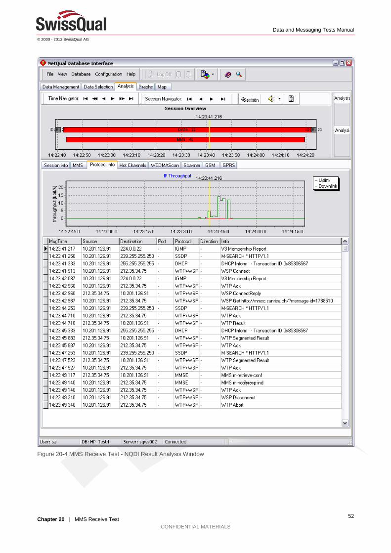
Data and Messaging Tests Manual
© 2000 - 2013 SwissQual AG
Chapter 20 | MMS Receive Test CONFIDENTIAL MATERIALS
52
Figure 20-4 MMS Receive Test - NQDI Result Analysis Window
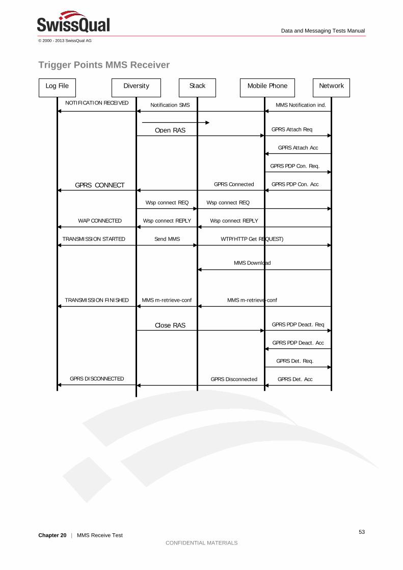
Data and Messaging Tests Manual
© 2000 - 2013 SwissQual AG
Chapter 20 | MMS Receive Test CONFIDENTIAL MATERIALS
53
Trigger Points MMS Receiver
Log File Diversity Mobile Phone Network Stack
Notification SMS
GPRS Attach Req
GPRS Attach Acc
NOTIFICATION RECEIVED
GPRS PDP Con. Req.
GPRS PDP Con. Acc GPRS CONNECT
GPRS Connected
Wsp connect REQ Wsp connect REQ
Wsp connect REPLY Wsp connect REPLY WAP CONNECTED
WTP/HTTP Get REQUEST) Send MMS TRANSMISSION STARTED
MMS Download
MMS m-retrieve-conf MMS m-retrieve-conf TRANSMISSION FINISHED
Close RAS GPRS PDP Deact. Req
GPRS PDP Deact. Acc
GPRS Det. Req.
GPRS Det. Acc GPRS Disconnected
Open RAS
MMS Notification ind.
GPRS DISCONNECTED
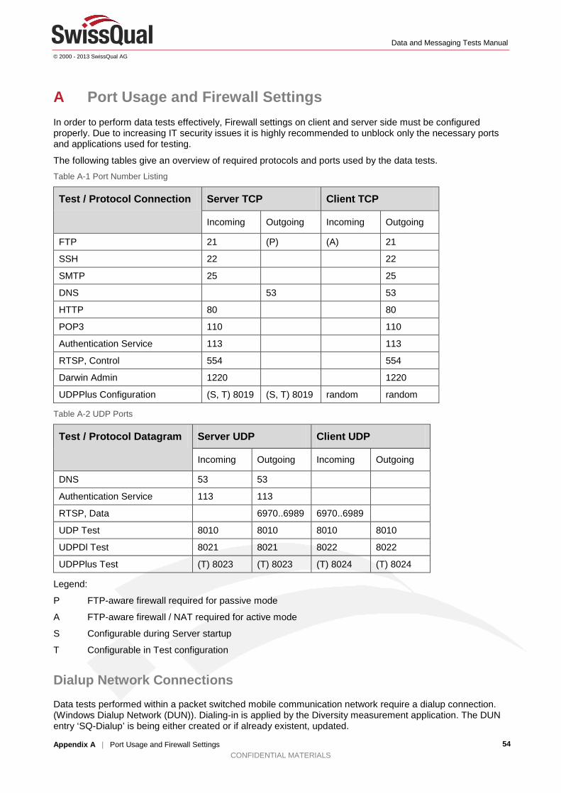
Data and Messaging Tests Manual
© 2000 - 2013 SwissQual AG
Appendix A | Port Usage and Firewall Settings CONFIDENTIAL MATERIALS
54
A Port Usage and Firewall Settings In order to perform data tests effectively, Firewall settings on client and server side must be configured properly. Due to increasing IT security issues it is highly recommended to unblock only the necessary ports and applications used for testing.
The following tables give an overview of required protocols and ports used by the data tests. Table A-1 Port Number Listing
Test / Protocol Connection Server TCP Client TCP
Incoming Outgoing Incoming Outgoing
FTP 21 (P) (A) 21
SSH 22 22
SMTP 25 25
DNS 53 53
HTTP 80 80
POP3 110 110
Authentication Service 113 113
RTSP, Control 554 554
Darwin Admin 1220 1220
UDPPlus Configuration (S, T) 8019 (S, T) 8019 random random
Table A-2 UDP Ports
Test / Protocol Datagram Server UDP Client UDP
Incoming Outgoing Incoming Outgoing
DNS 53 53
Authentication Service 113 113
RTSP, Data 6970..6989 6970..6989
UDP Test 8010 8010 8010 8010
UDPDl Test 8021 8021 8022 8022
UDPPlus Test (T) 8023 (T) 8023 (T) 8024 (T) 8024
Legend:
P FTP-aware firewall required for passive mode
A FTP-aware firewall / NAT required for active mode
S Configurable during Server startup
T Configurable in Test configuration
Dialup Network Connections Data tests performed within a packet switched mobile communication network require a dialup connection. (Windows Dialup Network (DUN)). Dialing-in is applied by the Diversity measurement application. The DUN entry ‘SQ-Dialup’ is being either created or if already existent, updated.

Data and Messaging Tests Manual
© 2000 - 2013 SwissQual AG
Appendix A | Port Usage and Firewall Settings CONFIDENTIAL MATERIALS
55
Note: Not all data tests require a previous dialup. Such as GPRS and PDP Tests!
The measurement PC dials up to the Internet provider. At this point, the marker GPRS Dial is written to the log file. This marker can be shown in the GSM Analysis window:
Figure A-1 GPRS markers in the GSM Analysis Window
The GPRS markers are also visible on the test-specific tab sheet (FTP, UDP, HTTP, Email, WAP).
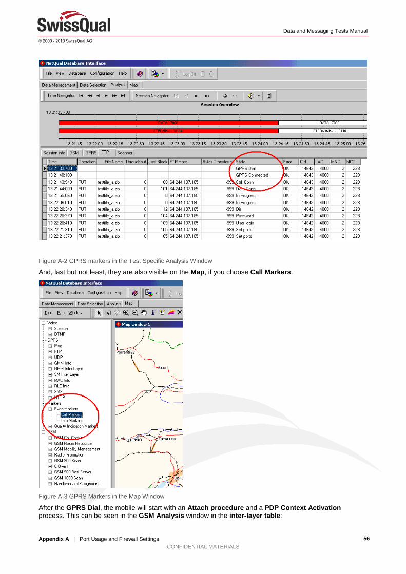
Data and Messaging Tests Manual
© 2000 - 2013 SwissQual AG
Appendix A | Port Usage and Firewall Settings CONFIDENTIAL MATERIALS
56
Figure A-2 GPRS markers in the Test Specific Analysis Window
And, last but not least, they are also visible on the Map, if you choose Call Markers.
Figure A-3 GPRS Markers in the Map Window
After the GPRS Dial, the mobile will start with an Attach procedure and a PDP Context Activation process. This can be seen in the GSM Analysis window in the inter-layer table:

Data and Messaging Tests Manual
© 2000 - 2013 SwissQual AG
Appendix A | Port Usage and Firewall Settings CONFIDENTIAL MATERIALS
57
Figure A-4 PDP Context Activation after GPRS Dial
as well as on the GPRS Analysis tab:
Figure A-5 GPRS PDP Context Activation
As soon as the mobile is connected to the Internet, you will get a GPRS Connect marker. If the dial-up fails,
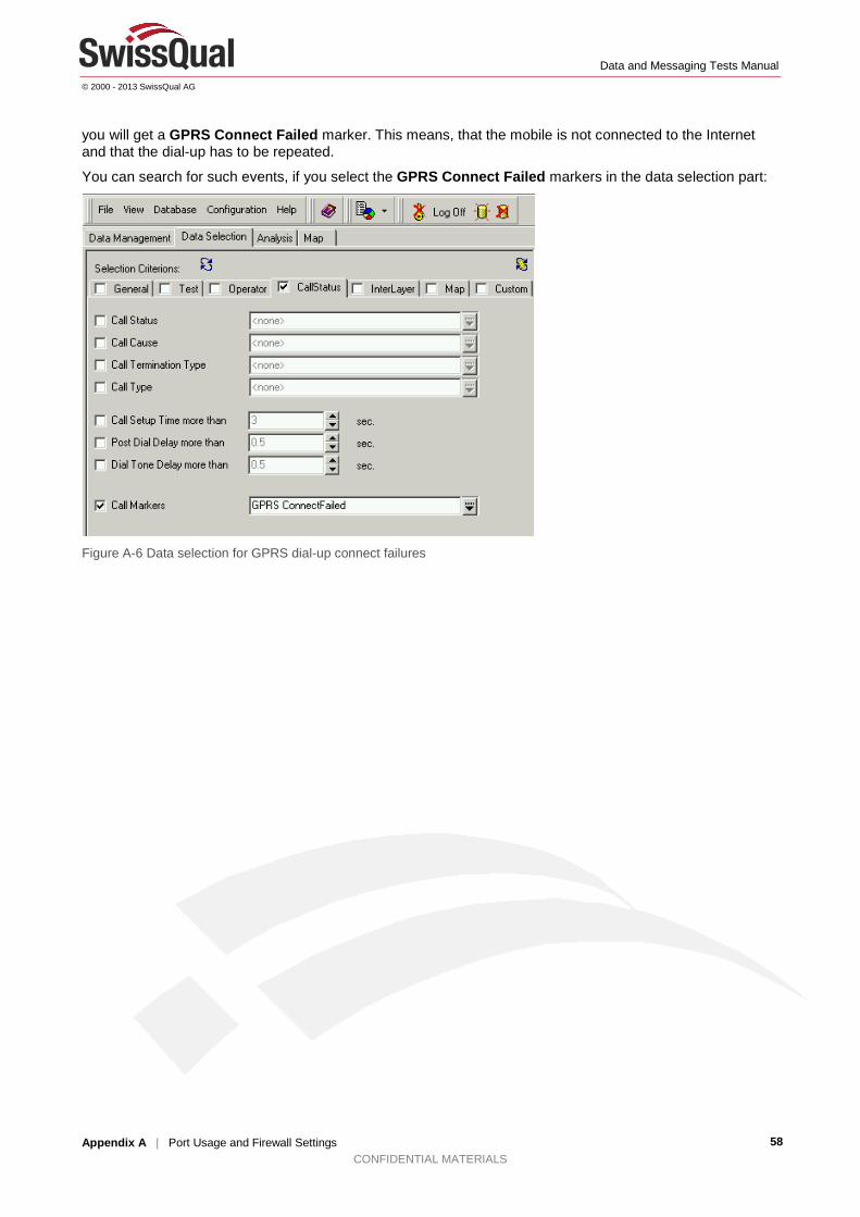
Data and Messaging Tests Manual
© 2000 - 2013 SwissQual AG
Appendix A | Port Usage and Firewall Settings CONFIDENTIAL MATERIALS
58
you will get a GPRS Connect Failed marker. This means, that the mobile is not connected to the Internet and that the dial-up has to be repeated.
You can search for such events, if you select the GPRS Connect Failed markers in the data selection part:
Figure A-6 Data selection for GPRS dial-up connect failures

Data and Messaging Tests Manual
© 2000 - 2013 SwissQual AG
Appendix B | Reducing the Effective Pause Time CONFIDENTIAL MATERIALS
59
B Reducing the Effective Pause Time The minimum length of the pause between data tests in NQView is 0 seconds. Diversity automatically adds the waiting for trace messages time to this pause to create the effective pause time. If you want to modify the waiting for trace messages time for the following data test types, you need to create a Windows Registry key:
• HTTP Transfer
• HTTP Browser
• FTP
• Capacity
• IPERF
• Ping Trace
• UDP
• MMS.
To change the waiting for trace messages time 1. In the Windows Registry Editor on the PCM, go to one of the following locations:
• In Windows 7 64bit, go to HKEY_LOCAL_MACHINE\SOFTWARE\ Wow6432Node\SwissQual\Diversity\Engine.
• In Windows 7 32bit, go to HKEY_LOCAL_MACHINE\SOFTWARE\ SwissQual\Diversity\Engine.
2. Right-click Engine, point to New, click String Value, and type WaitForEtherealMessages as the name.
3. Right-click the new WaitForEtherealMessages value and click Modify.
4. Type the length of the pause in milliseconds and click OK.