management & disposal of co in venezuela
TRANSCRIPT
Maria Emilia Escar
VENEZUELA
MANAGEMENT & DISPOSAL OF CO 2 IN VENEZUELA
IInntteerrnnaatt iioonnaall GGaass UUnniioonn RReesseeaarrcchh CCoonnffeerreennccee 1199--2211 OOccttoobbeerr 22001111

ABSTRACT
The Bolivarian Republic of Venezuela is considered as one of the nations with greatest Natural Gas potentiality in the world, mainly because of its vast reserves and strategic geographical location with a geopolitical significance.
Currently, certified reserves of Natural Gas in Venezuela reach 185 TCF, representing the 8th largest in the World. The Bolivarian Government of Venezuela is seeking to become the 4th largest gas producer in the world with the incorporation of about 264 TCF (expected), placing only behind Russia, Iran and Qatar.
Petróleos de Venezuela SA (PDVSA) as a responsible company to ensure proper exploration, production and marketing of hydrocarbons in the Bolivarian Republic of Venezuela has set as a goal to maximize the utilization of gas resources, following a value of chain supported on efficiency, safety, profitability and environmental awareness.
PDVSA GAS, branch of Petróleos de Venezuela, S.A, is currently developing new gas processing projects with the main purpose of valorizing gas streams coming from several production sources by means of incorporating Conditioned Natural Gas and Natural Gas Liquids (NGL) in different markets. In January, 2013, the delivery specification for conditioned natural gas will have to comply with standard n° 3568 declared by the Venezuelan Committee for Industrial Norms (COVENIN); on this regard, the content of CO2 and H2S shall not exceed 2% molar and 4.16 ppmv, respectively. As responsible guardian, PDVSA Gas, shall guarantee fulfillment of these specifications by installing Gas Sweetening Units able to decrease CO2 and H2S content up to the required values. Implantation of these units may involve, as a side effect, environmental emission of acid gas rich in CO2. To avoid these emissions a plan to Manage and Dispose CO2 in Venezuela was conceptualized. The plan initiates with the execution of three (3) phases to perform reservoir studies: a) first phase allows the identification of existing alternatives for CO2 disposal; b) second phase contemplates the selection of reservoirs for CO2 injection by following a hierarchy system; c) last phase is done to gather detailed studies in selected fields. Alongside phases 2 and 3, CO2 management facilities shall be designed, to condition the water saturated and H2S rich gas in desulphurization, dehydration and compression units located upstream the transmission line and injection system. The first plant to adopt the Management and Disposal plan for CO2 is the Soto NGL Extraction Plant, located in Anzoategui State (Eastern Venezuela) which is a project in development by PDVSA GAS. This Plant will process the Natural Gas production in order to treat it to meet the sale gas specification and by the same time recover the Natural Gas Liquids (NGL).
The design of Soto NGL Extraction Plant project contemplates two (02) Processing modules, each one with the capacity of 200 MMSCFD. The feed gas comes from San Tomé and AMO fields, located also in Anzoategui State. The CO2 content in these streams are 7 % molar approximated of CO2 and 13 ppmv (max.) of H2S. Therefore the sweetening units of Soto shall be designed to remove the CO2 and H2S in order to meet sales gas specification: less than 100 ppmv of CO2 and less than 4.16 ppm of H2S.
The CO2 volumes as the result of processing this Natural Gas is expected to be around 32.5 MMSCFD. Implantation date is set for late 2013; Soto will serve as a pilot for future installations foreseen from 2015 and on. By following this initiative Venezuela and PDVSA Gas are added to the list of pioneer countries and industries implanting and operating facilities designed to minimize global warning.

Figure 1. NGL Extraction Soto Plan and CO2 Management Project Location.
Jose (existing)
San Joaquín (existing)
SOTO I, II (2012 / 2013)
Domestic Market
A.M.OA.M.O. . -- PGAPGASAN TOMSAN TOMÉÉ
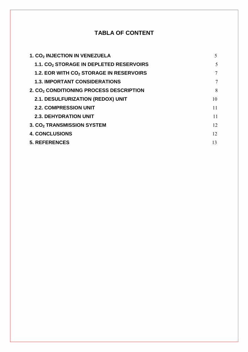
TABLA OF CONTENT
1. CO2 INJECTION IN VENEZUELA 5
1.1. CO2 STORAGE IN DEPLETED RESERVOIRS 5
1.2. EOR WITH CO2 STORAGE IN RESERVOIRS 7
1.3. IMPORTANT CONSIDERATIONS 7
2. CO2 CONDITIONING PROCESS DESCRIPTION 8
2.1. DESULFURIZATION (REDOX) UNIT 10
2.2. COMPRESSION UNIT 11
2.3. DEHYDRATION UNIT 11
3. CO2 TRANSMISSION SYSTEM 12
4. CONCLUSIONS 12
5. REFERENCES 13

1. CO2 INJECTION IN VENEZUELA
In 2013, PDVSA Gas will start – up the Soto NGL Extraction Plant, which represents the first gas processing plant to comply with new standard 3568 in order to provide sales gas meeting figures of 2% mol CO2 and 4.16 ppmv of H2S maximum.
To decrease the level of contaminants present in the feed gas, the Soto Plant will rely on Gas Sweetening Units implementing Amine solvent to absorb CO2 and H2S from the feed gas. Typically, during the regeneration phase of the Amine solvent acid gas rich in CO2, water and a considerable concentration in ppmv of H2S is desorbed from the solvent and then release to the atmosphere.
In order to avoid environmental release of acid gas and to find a way to give it proper use, PDVSA Gas developed a detailed study to select final disposition, with the participation of several specialists. The main options evaluated for CO2 disposal were:
• Injection for Enhanced Hydrocarbon Recovery (EOR). • Storage in depleted oil and gas fields. • Storage in deep saline aquifers.
Given the lack of saline aquifers in the zone, the first two (2) options were determined as most convenient. The following strategy was set in order to develop the CO2 disposal plan:
a) Early stage: storage in depleted gas / oil reservoirs.
b) Future stage: EOR in selected reservoirs.
For both stages the Zapatos – Mata R area was chosen by PDVSA as candidate to perform CO2 injection studies.
1.1. CO2 STORAGE IN DEPLETED RESERVOIRS
This stage was defined as a short term solution to dispose acid gas from NGL Extraction modules Soto I and Soto II, while more complex studies were developed to achieve EOR, as this alternative is the most appealing to PDVSA. Work flow followed is indicated in figure 2.
Figure 2. Work-flow for CO2 storage.

Activities completed included:
• Data gathering. • Reservoirs hierarchy: by geological data (rock type, geological context) and production data
(fluid type, volume of hydrocarbons on site). • Determination of potential of injection: impacts on pipeline size and header pressure were
determined with this exercise. Bigger diameter increases flexibility during injection in the reservoir at a certain pressure. The higher the pressure is in a reservoir, the less probable it becomes to inject CO2 with a steady header pressure.
Figure 3. Preliminary design of a CO2 injector.
Figure 4. Combined effects of pressure in the reservoir and header (pipeline diameter: 2,091”).

• Material balance: main objective was to determine pressure increase in the reservoir due to
CO2 injection.
Figure 5. Pressure variation in reservoir L2U MVR 64 due to the injection of CO2.
• Storage strategy: considers availability in the reservoirs to receive CO2 output from Soto’s modules from a period 0 to 20 years.
• Risk analysis: permitted to evaluate and alert possible impacts and ways of response in case of leakage (from pipeline or reservoir) and CO2 migration in the reservoir.
• Results from this phase identified as storage candidates the following reservoirs: S3S ZG304, R4U ZM312, M1U ZM311, L2U MVR64, L2L MVR96, L0L1 ZG303.
1.2. EOR WITH CO2 STORAGE IN RESERVOIRS
This part of the study will be completed on future instances.
1.3. IMPORTANT CONSIDERATIONS
Whether used for storage or EOR purposes, CO2 shall be treated and conditioned to avoid corrosion issues during transport and to minimize variations or upsets in the characteristics of the reservoir that may lead to undesirable aspects (such as precipitation) during injection.
Based on these considerations, the general scheme shown in figure 2 was conceptualized.
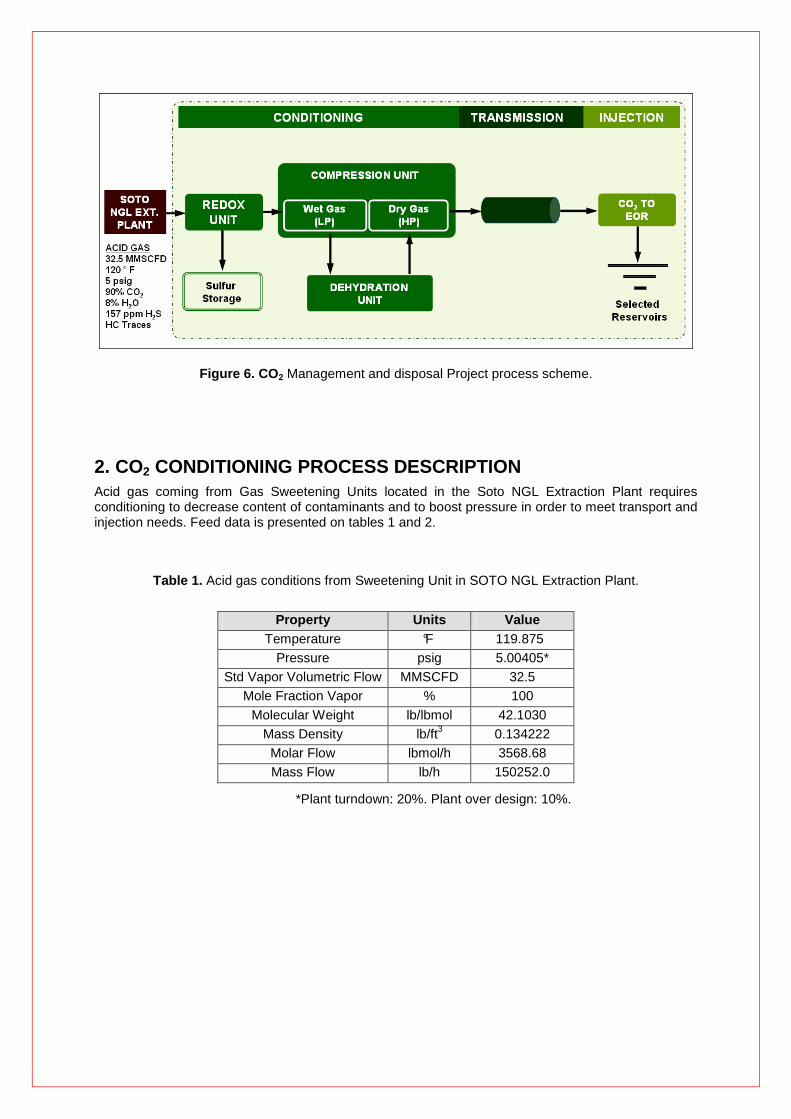
Figure 6. CO 2 Management and disposal Project process scheme.
2. CO2 CONDITIONING PROCESS DESCRIPTION Acid gas coming from Gas Sweetening Units located in the Soto NGL Extraction Plant requires conditioning to decrease content of contaminants and to boost pressure in order to meet transport and injection needs. Feed data is presented on tables 1 and 2.
Table 1. Acid gas conditions from Sweetening Unit in SOTO NGL Extraction Plant.
Property Units Value
Temperature °F 119.875 Pressure psig 5.00405*
Std Vapor Volumetric Flow MMSCFD 32.5 Mole Fraction Vapor % 100
Molecular Weight lb/lbmol 42.1030 Mass Density lb/ft3 0.134222 Molar Flow lbmol/h 3568.68 Mass Flow lb/h 150252.0
*Plant turndown: 20%. Plant over design: 10%.

Table 2. Acid gas composition.
Mole Fraction %
Water 8.27789 Nitrogen 3.95610E-05
CO2 90.9037 Methane 0.133861 Ethane 0.0515164
Propane 0.0216526
i-C4 0.00601042 n-C4 0.0101393 i-C5 0.00242287 n-C5 0.00278963
Hexane 0.00515199 Heptane 0.00312569
Octane 0.00320830 Nonane 0.00178914 Decane 0 Benzene 0.153061 Toluene 0.183558
Ethyl benzene 0.161183 o-Xylene 0.0405851
m-Xylene 0.0105345 p-Xylene 0.0121202 MDEA 7.24995E-13
Piperazine 4.04992E-14 H2S 0.0157018
Due to high content of H2S and H2O (table 2), desulfurization and dehydration treatment were identified as main facilities required to condition acid gas from Soto. Specifications to meet were established accordingly to minimize corrosion effect during transport and undesirable reactions with fluids present in the selected reservoirs during injection. Figures to be met are shown in table 3.
Table 3. Conditioned CO2 specifications.
Component Unit
H2S < 8 ppm Water < 5 ppmv
Pressure for Transport Unit 2000 psig
Temperature for Transport Unit Above 80 ° F
Pressure of injection Unit 2000 psig

2.1. DESULFURIZATION (REDOX) UNIT
Low pressure acid gas coming from Sweetening Units at a rate of 32.5 MMSCFD (5 psig and 120 °F) is routed to the Redox Facility by means of a blower. Gas flow is then cooled and sent to a separator to avoid carry over of liquid droplets within the gas phase.
SWEETSULF® was the Redox technology selected to remove H2S, given the following benefits: 1) effective operation for wide flowrate range, 2) high efficiency in component removal and 3) practical process for low sulphur production.
In the Redox Unit H2S turns into elemental sulphur by co-current contact of the acid gas with a catalyzed solution chelated with an organic ligand. Catalyst implemented is Iron (+2 and +3); the ligand is nitrilotriacetic acid (NTA) in aqueous solution. The following chemical reaction takes place inside a contactor:
H2S Oxidation: H2S + 2 Fe3+ ���� S + 2 Fe2+ + 2 H+ (Step 1)
Downstream contactor, acid gas containing less than 8 ppmv of H2S is sent to a separator where liquids are flashed. Gas stream from separator continues to a low pressure compression section.
Rich NTA solution is sent to a filtration package. Sulphur is obtained at the discharge of the final filtering station. NTA solution from primary filter is collected and regenerated inside an Oxidizer by reaction with air:
Fe2+ Oxidation: 2 Fe2+ + 2 H+ + ½ O2 ���� Fe3+ + H2O (Step 2)
Regenerated solution is returned to a storage tank for further process incorporation. Overall reaction in the Redox Unit is presented below:
Global reaction: H2S + ½ O2 ���� S + H2O
Figure 7. SweetSulf ® process scheme.
Sulfur production rate is expected to be 18.9 lb/h (dry basis). This sulfur is not high quality. Normally it will contain up to 30% wet basis. To obtain high quality sulphur an additional treatment is required.

2.2. COMPRESSION UNIT
Compression system to implement in the facilities contemplates use of an Integrally Geared machine, driven by a single electrical motor. Unit can be divided in two (2) sections:
• Wet gas compression (upstream gas dehydration unit). • Dry gas compression (downstream gas dehydration unit).
In the wet gas compression section, pressure is increased from 10 psig to 710 psig. Five (5) stages are required to reach this value. Once at 710 psig and 120 °F, wet CO 2 heads to the Dehydration Unit for water removal.
Downstream dehydration unit, dry gas is compressed from 690 psig to 2000 psig. Two (2) additional stages are needed to achieve the later figure.
2.3. DEHYDRATION UNIT
Wet gas is dehydrated in Molecular Sieves to decrease water content from saturation to less than 5 ppmv. Water removal in this unit is very important as it helps to prevent and avoid fluid condensation during transportation from Soto to the injection site. Defined cycles to run the unit are:
• Adsorption: 24 hours. • Hot regeneration cycle: 16 hours. • Cold regeneration cycle: 8 hours. • Total: 48 hours.
Figure 8. CO2 gas dehydration unit process scheme.

3. CO2 TRANSMISSION SYSTEM
Conditioned CO2 at a rate of 30 MMSCFD, 2000 psig and 120 °F is re ady for transport from Soto to the injection facilities, located in Zapatos – Mata R. Calculated length of the CO2 pipeline is 35 km.
Two (2) main routes were evaluated to transport conditioned CO2 (figure 3), resulting selected the northern tram (tram 2) and the common tram from Valve Station Casa Rosada, as it provided easier access, better constructability and less environmental impact.
Figure 9 . Main routes considered for CO2 transport from Soto to Zapatos – Mata R.
Fluid transport will be done at supercritical conditions (dense phase) to optimize piping material requirements and safety issues, such as leaking.
4. CONCLUSIONS
• PDVSA Gas aims avoid acid gas emissions (from NGL modules Soto I and Soto II) to the atmosphere by injecting 30 MMSCFD of acid gas (composed mainly by CO2) in selected reservoirs, targeting two (02) development stages: early (storage in depleted reservoirs) and future (EOR in reservoirs).
• Selected reservoirs in Zapatos – Mata R to store CO2 are:
S3S ZG304.
R4U ZM312.
Tram 1 Tram 2 Tram 3

M1U ZM311.
L2U MVR64.
L2L MVR96.
L0L1 ZG303.
• To achieve CO2 injection conditioning is required to decrease H2S and H2O contents in the acid gas from 157 ppmv to 8 ppmv and from saturation to 5 ppmv, respectively.
• CO2 transport and injection will be done at supercritical conditions (dense phase) as this
resulted to be more economical and adapted to the use than for example at gas phase.
5. REFERENCES
1. Leandri, P. “Estudio de las Opciones de Uso, Transporte y Almacenamiento del CO2
generado a partir de las plantas de procesamiento de PDVSA Gas”. PDVSA Gas. October, 2010.
2. Prosernat. “Process Book for CO2 Treatment and Conditioning in Soto”. PDVSA Gas.
June, 2011.

LIST TABLES
Table 1. Acid gas conditions from Sweetening Unit in SOTO NGL
Extraction Plant 8
Table 2. Acid gas composition 9
Table 3. Conditioned CO2 specifications 9
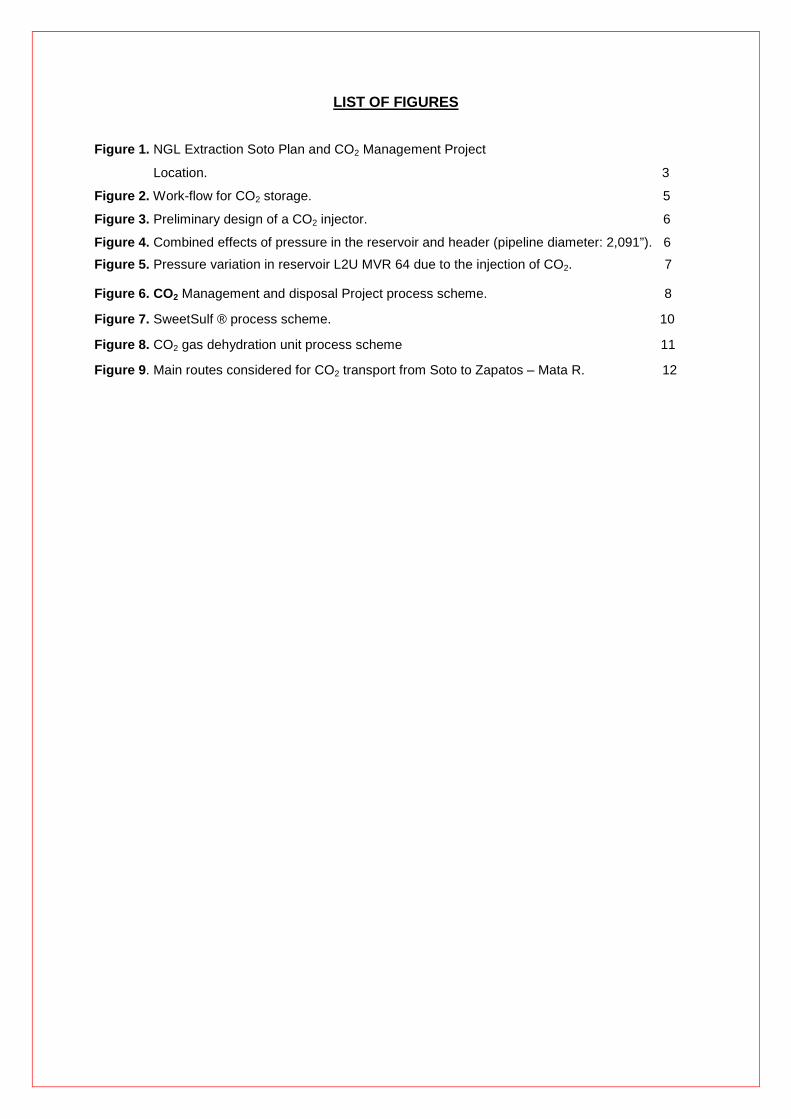
LIST OF FIGURES
Figure 1. NGL Extraction Soto Plan and CO2 Management Project
Location. 3
Figure 2. Work-flow for CO2 storage. 5
Figure 3. Preliminary design of a CO2 injector. 6
Figure 4. Combined effects of pressure in the reservoir and header (pipeline diameter: 2,091”). 6
Figure 5. Pressure variation in reservoir L2U MVR 64 due to the injection of CO2. 7
Figure 6. CO 2 Management and disposal Project process scheme. 8
Figure 7. SweetSulf ® process scheme. 10
Figure 8. CO2 gas dehydration unit process scheme 11
Figure 9 . Main routes considered for CO2 transport from Soto to Zapatos – Mata R. 12