man warranty process - new flyer · failure analysis and actions taken to date ... axle beam full 5...
TRANSCRIPT

MAN Engines & Components
MAN Warranty Process
MAN ENGINES & COMPONENTS MAN - MEC Warranty Process June 2015

MAN Engines & ComponentsWarranty process between New Flyer and MAN
The warranty validation process can be difficult at some times since components from different suppliers worktogether in a complex system and the root cause is not automatically the failed part If a failed part is part oftogether in a complex system and the root cause is not automatically the failed part. If a failed part is part of MAN‘s content of delivery, then the customer may be eligible for warranty reimbursement from New Flyer, but not necessarily from MAN.
The failure can be caused by another component, the vehicle design, the installation, the lack of maintenance and the use of non MAN approved service products and parts (including lubricants, operating conditions etc.)
There are the 3 possible scenarios: Failure is clearly due to MAN‘s content of delivery (Material and/or workmanship) Customer is eligible for warranty covered by MAN (Please see component coverage list for details)
F il i MAN‘ t t f d li (M t i l) b t f il i d b t t li d b MAN Failure is MAN‘s content of delivery (Material) but failure is caused by a component not supplied by MAN, design, assembly process or workmanship by others Customer is eligible for warranty covered by New Flyer, IAS or others
Failed part is MAN‘s or New Flyers content of delivery (material and/or workmanship), but customer did not adhere to recommended maintenance practice and schedule used unapproved service products lubricants oradhere to recommended maintenance practice and schedule, used unapproved service products, lubricants or tools or operated the bus under other than normal transit bus application conditions Warranty not covered by MAN or New Flyer or others
In any case: Water Contamination of the Axle or Components thereof is not Warrantable through MAN
MAN ENGINES & COMPONENTS MAN - MEC Warranty Process June 2015
y p gPlease refer to SB024 and SB027

MAN Engines & ComponentsWarranty process between New Flyer and MAN
When the Customer informs New Flyer about an issue the RPSM should be informed and work with the propertyWhen the Customer informs New Flyer about an issue, the RPSM should be informed and work with the property on the root cause analysis. The RPSM can always involve MAN for support, but should also consider seeking technical support from New Flyer‘s engineers and technical support team first. If requested by New Flyer or if MAN does see the need, MAN will contact the property directly (to the extent of MAN‘s competence) in coordination with New Flyer to resolve an issue quickly and to the customers satisfaction.
If a major component is effected or the expected repair cost exceeds $1,000, then New Flyer should inform MAN before a warranty repair is performed in order to avoid cost not covered under MAN‘s warranty. MAN is more than happy to assist with repair recommendations.
All t f t k h ll b id d b N Fl d l i d th h th iW t t N FlAll parts for warranty work shall be provided by New Flyer and claimed through the iWarranty system. New Flyer should inform MEC immediately if parts for warranty work are not available in their warehouses. Then, MEC will provide parts upon receipt of a P.O. from New Flyer if MEC has them in stock.
Always choose the least costly warranty repair (e.g. torn caliper boots > replace boots- not caliper> skim rotor > d ‘t l t )don‘t replace rotor)
NF customers shall never submit a warranty claim directly to MAN nor shall they directly contact MAN. Claims shall always be submitted through New Flyer‘s iWarranty system.
MAN ENGINES & COMPONENTS MAN - MEC Warranty Process June 2015
MAN Engines & ComponentsWear Items and Consumables
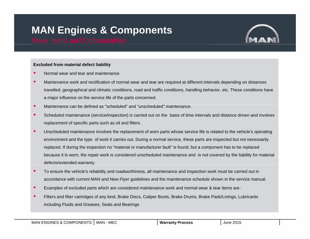
Excluded from material defect liability
Normal wear and tear and maintenanceNormal wear and tear and maintenance
Maintenance work and rectification of normal wear and tear are required at different intervals depending on distances
travelled, geographical and climatic conditions, road and traffic conditions, handling behavior, etc. These conditions have
a major influence on the service life of the parts concerned.
Maintenance can be defined as "scheduled" and "unscheduled" maintenance.
Scheduled maintenance (service/inspection) is carried out on the basis of time intervals and distance driven and involves
replacement of specific parts such as oil and filters.
Unscheduled maintenance involves the replacement of worn parts whose service life is related to the vehicle's operating
environment and the type of work it carries out. During a normal service, these parts are inspected but not necessarily
replaced. If during the inspection no “material or manufacturer fault” is found, but a component has to be replaced
because it is worn, the repair work is considered unscheduled maintenance and is not covered by the liability for material
defects/extended warranty. y
To ensure the vehicle's reliability and roadworthiness, all maintenance and inspection work must be carried out in
accordance with current MAN and New Flyer guidelines and the maintenance schedule shown in the service manual.
Examples of excluded parts which are considered maintenance work and normal wear & tear items are :
MAN ENGINES & COMPONENTS MAN - MEC Warranty Process June 2015
Filters and filter cartridges of any kind, Brake Discs, Caliper Boots, Brake Drums, Brake Pads/Linings, Lubricants
including Fluids and Greases, Seals and Bearings

MAN Engines & ComponentsRequired Information for axle failures
When the Customer informs New Flyer about an issue, the following information needs to be provided:needs to be provided: SR Number
Property Unit Number
Mileage
VIN #
Axle Serial number (17 digits)
Failure Date
Detailed discription of the failure
Caliper related failures require fully completed check sheet for warranty consideration
High quality Pictures (upon request)
Failure analysis and actions taken to date
Contact information at Property
Maintenance record (upon request)
MAN ENGINES & COMPONENTS MAN - MEC Warranty Process June 2015
Information about lubricants or parts used if applicable for failure
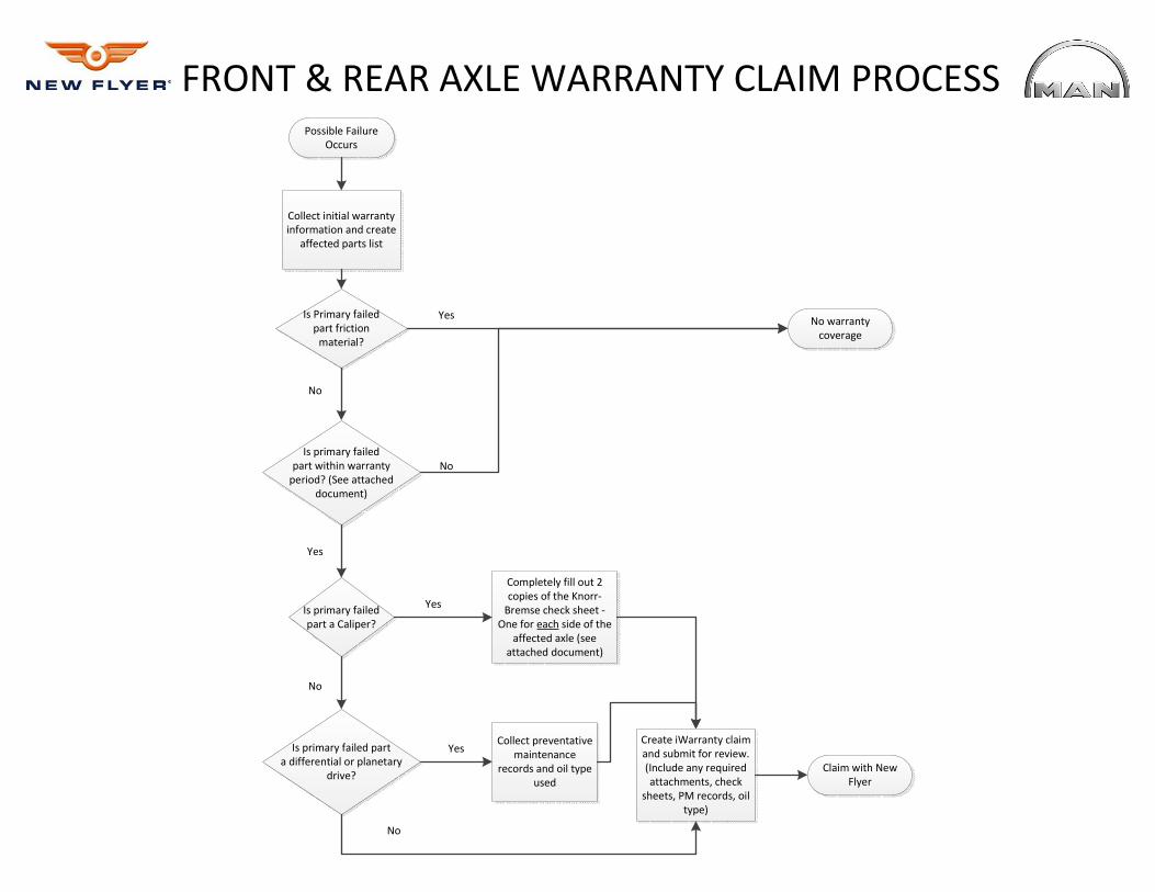
Possible Failure
Occurs
Collect initial warranty
information and create
affected parts list
Is Primary failed
part friction
material?
No warranty
coverage
Is primary failed
part within warranty
period? (See attached
document)
Is primary failed
part a Caliper?
Is primary failed part
a differential or planetary
drive?
Completely fill out 2
copies of the Knorr-
Bremse check sheet -
One for each side of the
affected axle (see
attached document)
Collect preventative
maintenance
records and oil type
used
Create iWarranty claim
and submit for review.
(Include any required
attachments, check
sheets, PM records, oil
type)
FRONT & REAR AXLE WARRANTY CLAIM PROCESS
No
Yes
Yes
No
No
No
Yes
Yes
Claim with New
Flyer

Part Category Warranty Period Part Category Warranty Period
Axle beam Full 5 years / 300,000 miles Axle housing Full 5 years / 300,000 miles
Track arm (drag link) Full 5 years / 300,000 miles Axle shafts Full 5 years / 300,000 miles
Tie rod Full 5 years / 300,000 miles Differential Full * 5 years / 300,000 miles *
Wheel hub unit Limited 2 2 years / 100,000 miles Wheel hub unit Limited 2 2 years / 100,000 miles
Brake caliper core Limited 2 ** 2 years / 100,000 miles ** Brake caliper core Limited 2 ** 2 years / 100,000 miles **
Caliper tappets and boots Limited 1 1 year / 50,000 miles Caliper tappets and boots Limited 1 1 year / 50,000 miles
Upper radius rod Limited 1 1 year / 50,000 miles Pinion seal Limited 1 1 year / 50,000 miles
Steering knuckle bearing Limited 1 1 year / 50,000 miles Brake pads Friction material no coverage
Steering knuckle seal Limited 1 1 year / 50,000 miles Brake rotor Friction material no coverage
Tie rod boots / ball joint Wear item 1 year / 50,000 miles
Toric seal (O-ring) Wear item 1 year / 50,000 miles BVA / End of life sensor Wear item 1 year / 50,000 miles
Brake pads Friction material no coverage
Brake rotor Friction material no coverage
* Requires supporting documentation of PM records.
** Requires supporting checklist fully completed.
Xcelsior Front Axle (VOK-07) Xcelsior Rear Axle (HY-1350)
Warranty Coverage Periods

Part Category Warranty Period Part Category Warranty Period
Axle beam Full 5 years / 300,000 miles Axle housing Full 5 years / 300,000 miles
Track arm (drag link) Full 5 years / 300,000 miles Axle shafts Full 5 years / 300,000 miles
Tie rod Full 5 years / 300,000 miles Differential Full * 5 years / 300,000 miles *
Wheel hub unit Limited 2* 2 years / 100,000 miles Planetary drive Limited 2 * 2 years / 100,000 miles *
Brake shoes Limited 2 2 years / 100,000 miles Wheel hub unit Limited 2* 2 years / 100,000 miles
S-Cam Limited 2 2 years / 100,000 miles Brake shoes Limited 2 2 years / 100,000 miles
S-Cam seals and bushings Limited 1 1 year / 50,000 miles S-Cam Limited 2 2 years / 100,000 miles
Slack adjuster Limited 1 1 year / 50,000 miles S-Cam seals and bushings Limited 1 1 year / 50,000 miles
Radius rod Limited 1 1 year / 50,000 miles Slack adjuster Limited 1 1 year / 50,000 miles
Steering knuckle bearing Limited 1 1 year / 50,000 miles Pinion seal Limited 1 1 year / 50,000 miles
Steering knuckle seal Limited 1 1 year / 50,000 miles Brake drums and linings Friction material no coverage
Tie rod boots / ball joint Wear item 1 year / 50,000 miles
Toric seal (O-ring) Wear item 1 year / 50,000 miles
Brake drums and linings Friction material no coverage
* Requires supporting documentation of PM records.
Low Floor Front Axle (V8-65L) Low Floor Rear Axle (HP-1352)
Warranty Coverage Periods

Fail date: Date:
Complaint:
New Flyer Vehicle type:
Chassis no. (VIN): Mileage:
Axle part number:
Axle serial number:
MGM e-stroke MGM non e-stroke
Knorr-Bremse
Front (steering) Center (tag)
Technician:
Brake chamber manufacturer:
New Flyer Inspection checklist for disc brakes
Axle manufacturer:
Vehicle manufacturer:
Customer:
Vehicle number:
Incoming tappet / outcoming tappet1. Measure running clearance of brake in cool down state (a + b): Nominal: 0.6 -1.2 mm / mm
In service date:
Brake manufacturer:
Axle model:
Requirements for warranty to be considered - one complete checklist must be completed for each caliper on the affected axle (2 checklists in total) Take digital photos of marked left (L) and right ( R) calipers (different temperature impact should be visible!).
Axle position in the vehicle: Rear (drive)
Axial Radial
Note: Apply service brake one time and slide the caliper back and forth prior beginning of the measurement, after the wheels are removed.
Brake type:
Knorr
Str
ee
t si
de
(L)
Cu
rb sid
e (R
)
Data tag brake caliper RData tag brake caliper L
Front of the
vehicle
Check affected side
2. If running clearance is less then 0.6 mm
mm mm
OK not OK
lncoming tappet / outcoming tappet / mm
Outboard pad:Inboard pad:
Comments
Make sure brake pads are installed in the caliper during adjuster check
- remove the brake air chamber ( c )
- measure running clearance again (a + b)
- if clearance OK - go to step 3
4. Check brake adjuster function (refer to New Flyer manual)
Never turn adjuster without shear adapter being fitted. If the shear torque of the shear adapter is exceeded, then it is designed to fail. Try again with a new (unused) shear adapter. With a second failure of the shear adapter the caliper must be exchangedsince internal damage is present. Do not use an open-ended spanner as this maydamage the adapter. Make sure the ring spanner or socket can turn freely clockwise during the following procedure.
3. Thickness of brake pads including back plate (30mm new)
Measure
b ca
Push inboard pad away from the tappets
Adjuster
Shear adapter
4
6 Port 12
Port 11
8
C
P
11 13 14
910
Thermal overloadNormal
0.6 -1.2 mm
Yes No
mm mm
OK not OK
Yes No
Loose Fixed
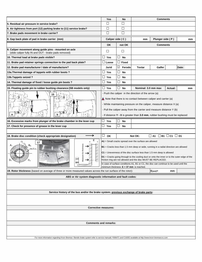
12. Brake pad manufacturer / date of manufacture? Jurid Ferodo Textar Galfer Date:
Yes No
Yes No
14. Thermal damage of fixed / loose guide pin boots ? Yes No
Yes No Actual: mm
Yes No
15. Floating guide pin to rubber bushing clearance (SB models only) Nominal: 3.0 mm max
Caliper side ( C )
10. Thermal load at brake pads visible?
11. Brake pad retainer springs connection to the pad back plate?
9. Caliper movement along guide pins - mounted on axle (slide caliper fully IN and OUT - brake pads removed)
13b.Tappets seized ?
16. Excessive marks from plunger of the brake chamber in the lever cup
7. Brake pads movement in brake carrier?
13a.Thermal damage of tappets with rubber boots ?
5. Residual air pressure in service brake?
6. Air tightness from port (12) parking brake to (11) service brake?
Comments
Comments
8. Gap back plate of pad in brake carrier (mm) Plunger side ( P )
- Push the caliper in the direction of the arrow (a)
- Note that there is no contact between caliper and carrier (a)
- While maintaining pressure on the caliper, measure distance X (a)
- Pull the caliper away from the carrier and measure distance Y (b)
- If distance Y - X is greater than 3.0 mm, rubber bushing must be replaced
15
a b
Yes No
Yes No
OK
C1 = Unevenness of the disc surface less than 1.5 mm deep is allowed
ABS or Air system diagnostic information and fault codes:
Service history of the bus and/or the brake system; previous exchange of brake parts:
Corrective measures:
Comments and remarks:
19. Rotor thickness (based on average of three or more measured values across the run surface of the rotor): E(ave)= mm
18. Brake disc condition (check appropriate designation)
A1 = Small cracks spread over the surface are allowed
17. Check for presence of grease in the lever cup
B1 = Cracks less than 1.5 mm deep or wide, running in a radial direction are allowed
D1 = Cracks going through to the cooling duct or onto the inner or to the outer edge of the friction ring are not allowed and the disc MUST BE REPLACED.
For more information regarding Knorr-Bremse / Bendix brake system refer to service manuals Y006471 and C16352 available at http://www.knorr-bremsecvs.com
Not OK: A1 B1 C1 D1
In case of surface conditions A1, B1 or C1, the disc can continue to be used until the minimum thickness E = 37 mm is reached.
17
Mea
sure
for
thic
knes
s