man-c24-0004 - cmg-cd24-r8 user's guide · august 2012 5. cd24-r8 the cd24-r8 can be accessed...
TRANSCRIPT

CMG-CD24R8
User's Guide
Part No. MAN-C24-0004
Designed and manufactured byGüralp Systems Limited3 Midas House, Calleva ParkAldermaston RG7 8EAEngland
Proprietary Notice: The information in this manual is proprietary to Güralp Systems Limited and may not be copied or distributed outside the approved recipient's organisation without the approval of Güralp Systems Limited. Güralp Systems Limited shall not be liable for technical or editorial errors or omissions made herein, nor for incidental or consequential damages resulting from the furnishing, performance, or usage of this material.
Issue B 2012-08-10

CD24-R8
Table of Contents
1 Introduction..............................................................................................................3
2 Getting started..........................................................................................................42.1 Hook-up diagrams.............................................................................................5
2.1.1 Single CD24-R8 with USB connection......................................................52.1.2 Single CD24-R8 with RS232 connection...................................................52.1.3 Single CD24-R8 with Ethernet connection................................................62.1.4 Multiple CD24-R8s without an EAM-R – USB connection.......................62.1.5 Multiple CD24-R8s without an EAM-R – Ethernet connection................72.1.6 Multiple CD24-R8s with an EAM-R...........................................................8
2.2 Adjustable Gain.................................................................................................9
3 Digitiser configuration...........................................................................................103.1 Configuration using an EAM...........................................................................103.2 Configuration using Scream............................................................................103.3 Configuration from the command line...........................................................10
4 Configuring networking.........................................................................................114.0.1 Using DeviceInstaller...............................................................................114.0.2 Using DHCP..............................................................................................144.0.3 Configuration with the Web interface.....................................................14
5 Connector pin-outs.................................................................................................165.1 Front panel.......................................................................................................16
5.1.1 Inputs A to H............................................................................................165.2 Rear panel........................................................................................................17
5.2.1 Power........................................................................................................175.2.2 GPS...........................................................................................................175.2.3 DATA........................................................................................................185.2.4 USB...........................................................................................................185.2.5 ETHERNET...............................................................................................195.2.6 GPS In/Out................................................................................................195.2.7 Inputs........................................................................................................20
6 Revision history......................................................................................................21
2 Issue B
User's Guide
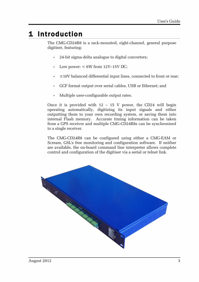
1 IntroductionThe CMG-CD24R8 is a rack-mounted, eight-channel, general purpose digitiser, featuring:
• 24-bit sigma-delta analogue to digital converters;
• Low power: < 6W from 12V–15V DC;
• ±10V balanced differential input lines, connected to front or rear;
• GCF format output over serial cables, USB or Ethernet; and
• Multiple user-configurable output rates.
Once it is provided with 12 – 15 V power, the CD24 will begin operating automatically, digitizing its input signals and either outputting them to your own recording system, or saving them into internal Flash memory. Accurate timing information can be taken from a GPS receiver and multiple CMG-CD24R8s can be synchronised to a single receiver.
The CMG-CD24R8 can be configured using either a CMG-EAM or Scream, GSL's free monitoring and configuration software. If neither are available, the on-board command line interpreter allows complete control and configuration of the digitiser via a serial or telnet link.
August 2012 3

CD24-R8
2 Getting startedThe following steps will enable you to connect and start using your CMG-CD24R8.
1. Connect your sensors (or other ±10V differential sources) to either the front-panel or rear-panel inputs. See section 5.1.1 on page 16 for the front-panel input pin-outs and section 5.2.1 on page 17 for the rear-panel input pin-outs.
2. If using a single CMG-CD24R8, connect your GPS receiver to the GPS input on the rear panel. This connector provides power to the GPS receiver and accepts NMEA and PPS inputs from the receiver to provide synchronisation.
3. If using multiple CMG-CD24R8s, connect your GPS receiver to the GPS input on the rear panel of the first digitiser. Connect a GPS “daisy-chain” cable (part number CAS-PEP-0045) between the GPS IN/OUT connectors of all digitisers to distribute the synchronisation signals.
4. Provide a data output connection as follows:
(a) If used with a CMG-EAM-R, connect a USB cable between the USB connector on the rear panel and a USB port on the CMG-EAM-R
(b) If used without a CMG-EAM-R, connect either:
i. a serial cable between the DATA connector on the rear panel and a serial port on a PC or laptop;
ii. a USB cable between the USB connector on the rear panel and a USB port on a PC or laptop; or
iii. a network cable between the ETHERNET connector on the rear panel and a network port on a switch, PC or laptop.
5. Connect the supplied power adapter to the POWER connector on the rear panel.
The hook-up diagrams on the following pages show the most common usage scenarios.
4 Issue B

User's Guide
2.1 Hook-up diagramsPlease note that only one of the connectors ETHERNET, USB and DATA can be used at any one time. A connection to the DATA port disables the ETHERNET and USB connectors. A connection to the USB port disables the ETHERNET connector.
2.1.1 Single CD24-R8 with USB connection
The USB connector on the CD24-R8 can be connected directly to a USB port on a PC or laptop.
The PC or laptop will see the CD24-R8 as a serial device on the USB bus and the operating system will allocate a COM port to it. The CD24-R8 can then be accessed using Scream (File Setup Com→ → Ports).
If the PC does not recognise the CD24-R8 as a virtual COM port, you can download drivers from http://www.ftdichip.com/Drivers/VCP.htm
2.1.2 Single CD24-R8 with RS232 connection
The DATA connector on the CD24-R8 can be connected directly to a serial port on a PC or laptop.
August 2012 5

CD24-R8
The CD24-R8 can be accessed directly using Scream (File Setup → → Com Ports). The default line speed for the DATA connector is 115,200 baud. This rate is suitable for all common usage scenarios and should not normally be changed.
2.1.3 Single CD24-R8 with Ethernet connection
The ETHERNET connector on the CD24-R8 can be connected to your LAN via a network hub or switch. Most modern PCs and laptops also allow a direct connection between the CD24-R8 and the Ethernet port without an intervening hub or switch.
The network interface is implemented using a Lantronix WiPort-NR module. To configure the network settings, please see Chapter 4 on page 11.
To view the digitiser's output in Scream, open the Network Control window ( + ) and add a new TCP server on port 10,002.
2.1.4 Multiple CD24-R8s without an EAM-R – USB connection
Multiple CD24-R8s can be connected to a single PC or laptop using a USB hub. The individual units will appear as separate COM ports and can be accessed from Scream as described in section 2.1.1 on page 5.
If the PC does not recognise the CD24-R8 as a virtual COM port, you can download drivers from http://www.ftdichip.com/Drivers/VCP.htm
The GPS receiver should be connected to only one CD24-R8. A GPS “daisy-chain” cable is used to pass timing information to other units in the rack.
The CD24-R8s are supplied with separate power supplies but, if a suitable DC power source is available, a “daisy-chain” power supply cable can be made up to run all the units from a single supply.
6 Issue B

User's Guide
2.1.5 Multiple CD24-R8s without an EAM-R – Ethernet connection
Multiple CD24-R8s can be connected to a single PC or laptop using an Ethernet hub. The individual units will appear as separate network devices and can be accessed from Scream as described in section 2.1.3 on page 6.
August 2012 7

CD24-R8
The network interfaces are implemented using Lantronix WiPort-NR modules. To configure the network settings, please see Chapter 4 on page 11.
The GPS receiver should be connected to only one CD24-R8. A GPS “daisy-chain” cable is used to pass timing information to other units in the rack.
The CD24-R8s are supplied with separate power supplies but, if a suitable DC power source is available, a “daisy-chain” power supply cable can be made up to run all the units from a single supply.
To view the digitisers' outputs in Scream, open the Network Control window ( + ) and, for each unit, add a new TCP server on port 10,002.
2.1.6 Multiple CD24-R8s with an EAM-R
The CMG-EAM-R is a data acquisition device with data-concentration, storage, processing and protocol-conversion facilities. It has been designed for use with up to seven CD24-R8 digitisers. For further information about the CMG-EAM-R, please see document MSH-EAM-0005, available from GSL support (email: [email protected]).
8 Issue B

User's Guide
Multiple CD24-R8s can be connected to a single CMG-EAM-R using USB cables, as shown.
The GPS receiver should be connected to only one CD24-R8. A GPS “daisy-chain” cable is used to pass timing information to other units in the rack.
The CD24-R8s are supplied with separate power supplies but, if a suitable DC power source is available, a “daisy-chain” power supply cable can be made up to run all the units from a single supply.
2.2 Adjustable GainIt is possible to adjust the gain of each input channel of the digitiser by connecting a resister between pins 2 and 4 of the relevant input connector (see section 5.1.1 on page 16 for the pin-outs of these connectors). The gain resistors affect inputs connected to either the front or rear input connectors. High-stability, low-noise components should be used.
The header information in the output packets will not be altered by fitting gain resistors. The gain indicated in the GCF blocks will always be unity. If InfoBlocks or CalVals are used to store calibration information, the values entered should be adjusted accordingly.
Nominal Gain Resistor value
Unity None fitted
×2 18 kΩ
×4 5.8 kΩ
×8 2.5 kΩ
×16 1.2 kΩ
August 2012 9

CD24-R8
3 Digitiser configurationThe CMG-CD24-R8 digitiser can be configured to select which data streams are transmitted at which sample rates. Parameters such as the stream identification numbers (Stream ID) can also be configured.
There are three ways to configure the digitiser:
• Using an EAM;
• Using Scream; or
• Using the digitiser's command line.
It is recommended that either Scream or an EAM is used for configuration.
3.1 Configuration using an EAMThe CMG-EAM range of acquisition units (including the EAM-R, which was designed for use with the CD24-R8) provides a simple web interface for configuring the CD24-R8.
This process is described in detail in the “Digitiser Configuration” chapter of the CMG-EAM manual, MAN-EAM-0003, which can be downloaded from www.guralp.com/documents/MAN-EAM-0003.pdf.
3.2 Configuration using ScreamGuralp Systems' free software package Scream provides a convenient user interface for configuring the CD24-R8 digitiser. For more information about Scream, please visit www.guralp.com/scream.
Use of Scream to configure digitisers is described in the “Configuring digitisers” chapter of the Scream manual, which can be downloaded from www.guralp.com/documents/MAN-SWA-0001.pdf.
3.3 Configuration from the command lineThe CD24-R8 can be configured from its own command line, which can be reached using the Terminal facility in Scream or the FORTH terminal emulator facility in the EAM's web interface. This is only recommended for advanced use and is not normally required.
Details of the CD24-R8's command-line interface are contained in MAN-CMD-0001, which is available from GSL support.
10 Issue B

User's Guide
4 Configuring networkingThe network interface of the CMG-CD24-R8 is implemented using an embedded Lantronix WiPort-NR module. This module can be configured using a built-in Web server.
Before you can access the Web server, however, you will need to assign the device an IP address. This can be done using Lantronix' DeviceInstaller utility for Microsoft Windows, or using a DHCP server. You will need a PC with a network interface installed.
4.0.1 Using DeviceInstaller
1. Download and install the DeviceInstaller utility from the Lantronix Web site at http://www.lantronix.com/
2. DeviceInstaller also requires the Microsoft .NET framework to be installed. If you do not have this already, it can be downloaded from http://www.microsoft.com/
3. Find out the MAC address of the CD24-R8's network interface. This should be printed on a label on the case.
4. If the DATA or USB ports on the rear of the CD24-R8 are connected to anything, disconnect them. The network interface is disabled if a serial connection is detected on either of these ports.
5. Connect the CD24-R8's ETHERNET port to the the PC's network interface, either using a crossover Ethernet cable or through a network switch or hub. Using a network switch or hub, you can connect several CD24-R8s to the same PC and configure them all at the same time.
DeviceInstaller will not work through routers or across the Internet. All the devices need to be on the same network segment as the PC.
6. Run DeviceInstaller.
DeviceInstaller's main window has two panels, a tree on the left (with Lantronix Devices at the top) and a table on the right.
The program will automatically look for Lantronix devices on all of your computer's network interfaces. If necessary, you can
August 2012 11

CD24-R8
narrow the selection by clicking on an entry in the tree on the left.
A WiPort-NR entry should appear in the table on the right, indicating that a device has been detected. If more than one WiPort-NR entry appears, DeviceInstaller has detected several devices.
For every detected device, the program shows the Hardware Address (i.e. the MAC address), and the IP address it is currently using. If your local network uses a DHCP server, the device will ask the DHCP server to assign it an address. Otherwise, a random address (APIPA) will be chosen automatically.
Automatic random addresses all begin with 169.254. The CD24-R8 will choose a different one every time it is power-cycled or rebooted.
7. The address of the CD24-R8 may be shown in red with the status Unreachable. If this happens, the digitiser and PC cannot communicate because they are not on the same subnet. Click Assign IP to start the IP configuration wizard.
12 Issue B

User's Guide
Follow the instructions in the wizard to set the IP address (or to configure DHCP if you are using a DHCP server). When you have finished, click Search to find the sensor with its new IP address.
8. If you want to configure the CD24-R8 to use a static IP address, use the Assign IP wizard as above, and click Search again.
9. Double-click on the entry which corresponds to the CD24-R8 you want to configure.
The right-hand panel will change to show the current properties of the device.
10.Switch to the Web Configuration tab, and click Go to open the Web configuration interface.
Alternatively, click Use External Browser to use your own Web browser to configure the digitiser.
11.Follow the steps in section 4.0.3 on page 14 to configure the module using its Web interface.
August 2012 13
CD24-R8
4.0.2 Using DHCP
If you cannot install DeviceInstaller on your PC, or do not wish to, you can also get access to the CD24-R8 using a standard DHCP server. In most cases you will need to have administrative privileges to do this.
1. Install and start the DHCP service on your PC.
2. Connect the CD24-R8's ETHERNET port to the the PC's network interface, either using a crossover Ethernet cable or through a network switch or hub. Using a hub, you can connect several CD24-R8s to the same PC and configure them all at the same time.
DHCP will not work through routers or across the Internet. All the devices need to be on the same network segment as the PC.
3. Monitor the DHCP server to find out what IP address it gives to each digitiser.
4. To configure a device, enter its IP address into a web browser.
4.0.3 Configuration with the Web interface
Once you have access to the WiPort-NR's Web interface, you can configure it with its proper settings.
1. The Web page is divided into three. A menu on the left switches between pages of configuration options on the right. There is also a banner at the top, which tells you the current firmware revision and the MAC address.
To navigate around the Web site, click on the entries in the left-hand menu. When you have made changes to the settings on any page, save them by clicking OK before you leave the page.
2. The WiPort-NR has two serial channels, exposed on TCP ports 10,001 and 10,002. The channel connected to port 10,001 is unused. Channel 2 (port 10002) is connected to the CD24-R8's digital output, unless you have connected a PC or laptop via either a serial data cable to the DATA connector or a USB cable to the USB connector. If either of these connections are detected, the CD24-R8 will send data streams through that interface rather than to the WiPort-NR.
14 Issue B

User's Guide
Click on Channel 2 – Serial Settings.
Set the Baud Rate to 115,200. This is the default baud rate for the CD24-R8's digital output. If you change the baud rate in Scream!, using an EAM or from the command line, you must come back to this page and change the Baud Rate setting. It is recommended that this setting is not changed.
The remaining settings can be left at their default values. Click OK to save your changes.
For full information on the WiPort-NR's configuration options, please refer to the WiPort-NR documentation, which is available on the Lantronix Web site at http://www.lantronix.com/
3. When you have finished setting up the WiPort-NR, apply the new settings by clicking Apply Settings. The WiPort-NR will re-boot with the new settings in effect.
If the WiPort-NR is using an automatically chosen random IP (beginning with 169.254), the IP address will change when you do this. You will need to go back to DeviceInstaller to find out the new IP address.
August 2012 15

CD24-R8
5 Connector pin-outs
5.1 Front panel
5.1.1 Inputs A to H
The front-panel input connectors are 5-way, 3.81mm headers, manufactured by Pheonix Contact, part number MC 1,5/ 5-G-3,81. Suitable mating connectors are provided but can also be obtained from good electronic component retailers.
Pin Function
1 Inverting input (-ve)
2 Gain resistor
3 Signal ground
4 Gain resistor
5 Non-inverting input (+ve)
Wiring details for the compatible plug, Pheonix Contact part number 1827004.
16 Issue B

User's Guide
5.2 Rear panel
5.2.1 Power
The power connector is a Switchcraft 712A 2.5mm barrel connector wired with the tip +ve and the shield -ve. A 12 - 15V DC regulated supply must be used. There is some variation amongst connectors labelled “ 2.5mm barrel” so it is recommended that mating connectors are purchased from GSL.
5.2.2 GPS
This is a standard 6-pin “mil-spec” socket, conforming to MIL-DTL-26482 (formerly MIL-C-26482). A typical part-number is 02E-10-06S although the initial “02E” varies with manufacturer.
Suitable mating connectors have part-numbers like ***-10-06P and are available from Amphenol, ITT Cannon and other manufacturers.
Pin Function
A Isolated ground
B RS232 receive from GPS
C RS232 transmit to GPS
D PPS
E not connected
F Power +5 V
Wiring details for the compatible plug, ***-10-06P, as seen from the cable end (i.e. when assembling).
August 2012 17
CD24-R8
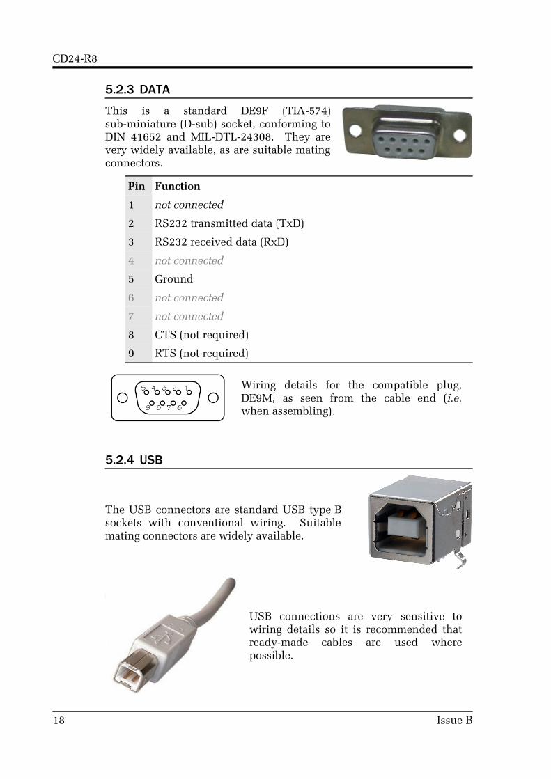
5.2.3 DATA
This is a standard DE9F (TIA-574) sub-miniature (D-sub) socket, conforming to DIN 41652 and MIL-DTL-24308. They are very widely available, as are suitable mating connectors.
Pin Function
1 not connected
2 RS232 transmitted data (TxD)
3 RS232 received data (RxD)
4 not connected
5 Ground
6 not connected
7 not connected
8 CTS (not required)
9 RTS (not required)
Wiring details for the compatible plug, DE9M, as seen from the cable end (i.e. when assembling).
5.2.4 USB
The USB connectors are standard USB type B sockets with conventional wiring. Suitable mating connectors are widely available.
USB connections are very sensitive to wiring details so it is recommended that ready-made cables are used where possible.
18 Issue B

User's Guide
5.2.5 ETHERNET
The ETHERNET connector is a standard 8P8C modular socket, conforming to TIA/EIA-568-B. It is compatible with standard 10Base-T or 100Base-TX twisted-pair Ethernet connectors.
Pin Function
1 Tx+
2 Tx-
3 Rx+
4 Not connected
5 Not connected
6 Rx-
7 Not connected
8 Not connected
5.2.6 GPS In/Out
The GPS “daisy-chain” connector is a 0.1 inch pitch header. Compatible sockets are available from good electronic component retailers.
Pin Function
1 NMEA non-inverting input (+ve)
2 NMEA inverting input (-ve)
3 Ground
4 Ground
5 PPS non-inverting input (+ve)
6 PPS inverting input (-ve)
Wiring details for the compatible socket.
August 2012 19

CD24-R8
5.2.7 Inputs
The rear-panel input connector is a standard DB25M sub-miniature (D-sub) chasis-plug, conforming to IEC 60807-3, DIN 41652 and MIL-DTL-24308. They are very widely available, as are suitable mating connectors.
Pin Function
1 Channel 1 - Signal ground
2 Channel 1 - Non-inverting input (+ve)
3 Channel 2 - Inverting input (-ve)
4 Channel 2 - Signal ground
5 Channel 3 - Non-inverting input (+ve)
6 Channel 4 - Inverting input (-ve)
7 Channel 3 - Signal ground
8 Channel 5 - Non-inverting input (+ve)
9 Channel 6 - Inverting input (-ve)
10 Channel 6 - Signal ground
11 Channel 7 - Non-inverting input (+ve)
12 Channel 8 - Inverting input (-ve)
13 Channel 8 - Signal ground
14 Channel 1 - Inverting input (-ve)
15 Channel 4 - Signal ground
16 Channel 2 - Non-inverting input (+ve)
17 Channel 3 - Inverting input (-ve)
18 Channel 5 - Signal ground
19 Channel 4 - Non-inverting input (+ve)
20 Channel 5 - Inverting input (-ve)
21 Channel 7 - Signal ground
22 Channel 6 - Non-inverting input (+ve)
23 Channel 7 - Inverting input (-ve)
24 Channel 1 - Signal ground (duplicate - not required)
25 Channel 8 - Non-inverting input (+ve)
20 Issue B

User's Guide
6 Revision history2012-08-10 B Corrected connector description for DB25 inputs2012-02-01 A New document
August 2012 21