make the change to quality! specify - val-matic valve ... · the american-bfv® is designed,...
TRANSCRIPT

www.valmatic.com
Proven Design
Preferred Features
Advanced Technology
AM
ERICAN - BFV®
BU
TTERFLY VALVE
AWWARubber SeatedButterfly Valve
Val-Matic’s quality of design and meticulousworkmanship has set the standards by whichall others are measured. Quality design fea-tures such as an Ener•G® efficient AWWA BallValve with fusion bonded epoxy andadjustable resilient seating....Cam-Centric®
Plug Valves with more requested features thanany other eccentric plug valve....the American-BFV® Butterfly Valve that provides fieldreplaceable seat without the need for specialtools....high strength and wear resistant alu-minum bronze trim as standard for Tilted Disc®
Check Valves....combined resilient/metal tometal seating for Silent Check Valves....heavyduty stainless steel screened inlet on Sure SealFoot Valves....unrestricted full flow areathrough Swing-Flex® and Surgebuster® CheckValves....and stabilized components that pro-vide extended life of the Dual Disc® CheckValves....Type 316 stainless steel trim as stan-dard on Air Release, Air/Vacuum andCombination Air Valves....the VaultSafe® fami-ly of products includes the FloodSafe® InflowPreventer, FrostSafe® two-way damper andthe VentSafe® vent pipe security cage.These features coupled with our attentionto detail put Val-Matic Valves in a class bythemselves.
Val-Matic is totally committed to providing thehighest quality valves and outstanding serviceto our customers. Complete customer satisfac-tion is our goal.
Make the Change to Quality!
Specify
Val-Matic Valve and Manufacturing Corp.905 Riverside Drive, Elmhurst, IL 60126
Phone: 630-941-7600 Fax: 630-941-8042www.valmatic.com
Copyright © 2010 Val-Matic Valve & Mfg. Corp.ISO 9001:2008 certified company
12/10
Bulletin 2000
WQA Certified Lead-FreeNSF/ANSI 61 Certified

2
A. BodyAvai lab le in Wafer, F langed,Mechanical Joint and Flange xMechanical Joint End Connections inAWWA Classes 150B and 250B.
B. Body Seat360° uninterrupted body seat withno shaft penetration insures leakfree performance. Type 316 StainlessSteel provides long life and corrosionfree mating surface for resilient seat.
C. Ductile Iron DiscDuctile Iron provides strength andrigidity to withstand dynamic forcesfrom flow and pressure transients.The added strength allows the discdesign to have a smaller cross sectionproviding improved headloss charac-teristics.
D. Rubber SeatSpecial formulated elastomers forchemical resistance and long cycle
life. The 360° resilient seat is uninter-rupted for positive seating.
E. ShaftStainless Steel shafts meet AWWAC504 diameter requirements .Through-shafts provided standard onsizes 3”- 24” and available on 30”and larger when specified.
F. Tangential Taper PinsStainless Steel Taper Pins with locknut and o-ring seal utilize tangentialforces of the taper pin and lock nutto provide the most secure methodavailable of locking the disc to theshaft.
G. Tri-Loc™ SeatRetention System
With over 35 years of provendependability the Tri-Loc™ SeatingSystem is easily adjusted and fieldreplaceable. All seat hardware isType 316 Stainless Steel.
H. Traveling Nut ActuatorThe traveling nut design providescharacterized closure during the lasthalf of travel. Exclusive externallyadjustable stops are rated to 450 ft-lbs of input torque. Standard FA10motor mounting flange providesease of automation.
I. Shaft SealShaft seal is a self-adjusting/wearcompensating V-Type packing. Pack-ing is easily replaced withoutremoval of the valve from the line.
J. Sleeve BearingsLow friction bearings are self-lubri-cating and non-corrosive, for along, trouble-free life.
K. Thrust BearingFactory-set bronze thrust bearingassures proper centering of valvedisc. Thrust bearings are fieldadjustable in sizes 30” and larger.
A
B
CD
E
F
G
J
I
K
Feature Highlights
*WQA Certified Lead Free*NSF/ANSI 61 Certified
H

The American-BFV® is designed,manufactured, and tested to meetall AWWA C504 and C516 require-ments including performancetests, leakage tests, and hydrostat-ic testing. Third-party Proof ofDesign Testing was successfullycompleted and flow testing wasperformed at the Utah StateHydraulics Lab, one of the premiertesting labs in the world.
With thousands of field installa-tions throughout the world, theAmerican-BFV® design has provendependable since 1971.
The valves are certified for use indrinking water in accordance withNSF/ANSI 61 and are WQACertified Lead-Free.
The American-BFV® provides thefeatures that engineers and usershave requested and are includedin the AWWA C504 and C516Butterfly Valve standards. TheAmerican-BFV® is designed to pro-vide long life and trouble-freeperformance. If maintenancebecomes necessary, the valve isalso designed for easy field ser-vice. The shaft seal incorporatesV-type packing which is easilyreplaced in the field withoutremoval from the line. Adjust-ment of the resilient seat is easilyperformed with a torque wrench,as compared to epoxy filled seatsthat require special equipmentand materials or bonded seatsthat cannot be replaced or adjust-ed in the field.
The unique Tri-Loc™ seat reten-tion system assures seat integrity
by securing the seat throughthree different mechanical meth-ods to assure long-term depen-dable service, See Figure 1. Allseat designs provide excellentseating but only the Tri-Loc™ pro-vides ease of adjustment orreplacement in the field if everneeded.
The American-BFV® disc is ductileiron in all sizes. The addedstrength allows the disc design tohave a smaller cross section pro-viding improved headloss charac-teristics. The American-BFV® willwithstand flow rates and pressuretransients beyond the maximumAWWA pressure rating.
Incorporating the latest in valvetechnology assures a high-qualityvalve that will provide long ser-vice. The design process utilizedSolid Modeling and Finite ElementAnalysis (FEA) of the key structu-ral components. Flow and torquedata was derived from flow tests,mathematical models and Com-putational Fluid Dynamics (CFD).Manufacturing technology usesautomated process control in thefoundry and ISO 9001 controlledmanufacturing processes. Everyvalve is tested in accordance withAWWA C504 and C516.
The Tri-Loc™ seat retention system provides reliable sealingand positive mechanical retention of the valve seat whileallowing easy adjustment or replacement in the field.
The seat is secured by three methods: 1) clamp force, 2)through the seat bolting and 3) opposing machined registersin the disc and seat retaining ring. Clamp force is provided bytightening the Nylok* cap screws. Tightening the screwsapplies pressure to the serrated seat retaining ring which inturn creates a “clamp force” on the rubber molded seat.These same cap screws provide through-bolting seat retentionby passing through precision molded holes in the rubber seat.Finally, molded shoulders in the rubber seat are captured bymachined registers in the disc and retention ring preventingoutward movement of the seat.
*Nylok is a registered trademark of Nylok corporation. 3
SEAT RETAINING RING
RUBBER SEAT
DISC
CAP SCREW
THROUGH SEATBOLTING
NYLOKPLUG
US Patent No: 6,244,567
Figure 1. Tri-Loc™ Seat Retention System
Feature BenefitsP R O V E ND E S I G N
P R E F E R R E DF E A T U R E S
A D V A N C E DT E C H N O L O G Y

4
Headloss Chart
Valve ConstructionPRESSURE RATINGS MATERIALS OF CONSTRUCTION
MAXIMUM PRESSURE RATINGS
SERIES CONNECTION AWWAClass
CWP(psig)
2000 ANSI 125# Gray Iron Flange 150B 150
2100 AWWA MJ Gray Iron 150B 150
2200 ANSI 250# Ductile Iron Flange 250B 250
2300 AWWA MJ Ductile Iron 250B 250
2400 ANSI 125# Ductile Iron Flange 250B 250
2500 ANSI 125# Gray Iron Wafer 150B 150
2600 ANSI 125# FLG x MJ Gray Iron 150B 150
COMPONENT STANDARD OPTIONAL
150B Body3”-72”
Cast Iron ASTMA126, Class B
Ductile Iron, BronzeStainless Steel
Steel150B Body78”-108”
250B Body3”-108”
Ductile Iron ASTM A536Gr. 65-45-12
BronzeStainless Steel
Steel
DiscDuctile Iron ASTM A536
Gr. 65-45-12
BronzeStainless Steel
Steel150B Shaft
3”-72”Stainless Steel ASTM
A276 Type 304Stainless Steel
Type 316, Monel150B Shaft78”-108”
250B Shaft3”-108”
Stainless Steel ASTMA564 Type 630, H1150
Monel
Resilient Seat Buna-N EPDM, VitonBody, Seat and
HardwareType 316 Stainless Steel Monel
Shaft Bearings3” - 24”
Nylatron Teflon, Bronze
Shaft Bearings 30” and Larger
Teflon-Lined, Fiberglass-Backed
Teflon-Lined,Stainless Steel orBronze Backed
100
200
300
400
500
600
700
800
1,00
0
2,00
0
3,00
0
4,00
0
5,00
06,
000
7,00
08,
000
10,0
00
20,0
00
30,0
00
40,0
00
50,0
0060
,000
70,0
0080
,000
100,
000
200,
000
300,
000
400,
000
500,
000
600,
000
700,
000
800,
000
1,00
0,00
0
.03
.04
.05
.06
.07
.08
.1
.2
.3
.4
.5
.6
.7
.81
2
310
8765
4
3
2
1
.8
.7
.6
.5
.4
.3
.2
.1
30 40 50 60 70 80 100
200
300
400
500
600
700
800
1,00
0
2,00
0
3,00
0
4,00
0
5,00
0
6,00
07,
000
8,00
0
10,0
00
20,0
00
30,0
00
40,0
00
50,0
00
60,0
0070
,000
80,0
00
100,
000
200,
000
TYP
ICA
L VA
LVE
SIZ
ING
RA
NG
E10
20
.02
15
5
.06
.07
.08
96”
84”
72”60”48”
42” 54” 66”
4 FEET/SECONDVELOCITY
20 FEET/SECONDVELOCITY
15 FEET/SECONDVELOCITY
10 FEET/SECONDVELOCITY
5 FEET/SECONDVELOCITY
16 FEET/SECONDVELOCITY
30”
36”24”
20”
18”
16”
14”
12”
10”
8”
6”
4”
78”90”
102”
108”
3”
CUBIC METERS PER HOUR
FLOW OF WATER IN GALLONS PER MINUTE
HE
AD
LO
SS
IN
FE
ET
OF
WA
TE
R
ME
TE
RS
OF
WA
TE
R
FlowCoefficients
Size Cv
3 380
4 590
6 1,430
8 2,750
10 4,300
12 6,550
14 8,350
16 11,800
18 15,000
20 18,600
24 27,000
30 42,000
36 61,900
42 87,100
48 114,000
54 144,000
60 180,000
66 221,000
72 266,500
78 316,000
84 366,000
90 420,500
96 478,500
102 540,000
108 605,500
AM
ERICAN - BFV®
BU
TTERFLY VALVE

Val-Matic manufactures a wide variety of manual and power actuators that include traveling nut actuators, wormgears, cylinders and motors. In addition Val-Matic valves are easily adaptable for mounting custom actuators suchas: vane, spring-return, rack and pinion, electro-hydraulic, air/oil and other specified cylinder or electric motoractuators.Val-Matic control systems provide reliable power and control of hydraulic actuated butterfly valves. Val-Matic con-trol panels use the highest quality components and provide field adjustable operation of valves. Oil accumulatorsystems provide hydraulic power for valves even after power failure. Electrical panels provide for remote monitor-ing of valve operation and alarm conditions.
5
Actuation/Controls
LINK AND LEVER
TRAVELING NUT ACTUATOR
Val-Matic's traveling nut manual actuators are designed to specificallymatch the torque characteristics of Val-Matic Butterfly Valves and are builtin accordance with AWWA Standards. The traveling nut actuator providescharacterized closure which allows the valve to slowly close during the lasthalf of travel to reduce pipeline surges. Val-Matic actuators have the exclu-sive feature of externally adjustable stops rated to 450 ft-lbs of inputtorque.
WORM GEAR MANUAL ACTUATOR
Val-Matic's worm gearactuators provide precisequarter turn actuation in
accordance with AWWAStandards. Worm gears
include externally adjustable mechanicalstops to control end of valve travel.Optional spur gear assemblies are provid-ed to increase mechanical advantagethereby reducing the handwheel and nutinput torques.
Val-Matic's cylin-der actuators are
designed and builtin accordance withAWWA C541 for
Hydraulic Actuators. Theyprovide reliable character-ized closure and featureexternal ly adjustableclosed stops. Cylinders areconstructed of stainlesssteel for air, oil or watersupply media to 150 psig.Cylinder actuators can bee q u i p p e d w i t h l i m i tswitches, positioners, sole-noid valves, and flow con-trol valves to provide con-trol functions.
ELECTRIC MOTOR
ACTUATION
CONTROL SYSTEMS
Val-Matic's motorizedtraveling nut and wormgear actuators aredesigned to match thetorque characteristicsof quarter turn valves.The actuators are builtin accordance withAWWA Standard C542for Electric Actuatorsand are equipped withthermal over loads ,torque switches andlimit switches to protectthe actuator and valve.
SLOTTED LEVER
AIR, OIL AND WATER
CYLINDER ACTUATOR Oil Accumulator Systemsconsist of redundant oilpumps and air compres-sors piped to an ASMEcertified air-over-oilaccumulator tank. Thesystem provides a cleanand reliable oil supply tooperate all of the pumpcontrol valves even afterpower outages.
Hydraulic Control Panelsoperate pump control valvesusing air, oil, or water andinclude solenoid and flowcontrol valves for slow open,slow close, and emergencyshutdown. The panels fea-ture rugged corrosion resis-tant piping in a NEMA 4Xenclosure with window,shutoff valve, and supplypressure gauge.
Electric Control Panels pro-vide the interface betweenthe hydraulic control paneland the pump motor con-trols. The NEMA 4X paneldisplays valve position andalarm conditions withheavy-duty pilot lights andcontrols critical system func-tions with socket-type relaysand timers.
6
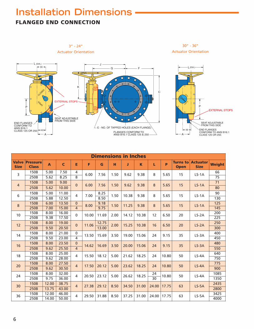
FLANGED END CONNECTION
Dimensions in InchesValveSize
PressureClass A C E F G H J K L P Turns to
OpenActuator
Size Weight
3150B 5.00 7.50 4
6.00 7.56 1.50 9.62 9.38 8 5.65 15 LS-1A66
250B 5.62 8.25 8 75
4150B 5.00 9.00
0 6.00 7.56 1.50 9.62 9.38 8 5.65 15 LS-1A71
250B 5.62 10.00 80
6150B 5.00 11.00
4 7.008.25
1.50 10.38 9.38 8 5.65 15 LS-1A90
250B 5.88 12.50 8.50 130
8150B 6.00 13.50 0
8.009.18
1.50 11.25 9.38 8 5.65 15 LS-1A125
250B 7.00 15.00 4 9.75 145
10150B 8.00 16.00
0 10.00 11.69 2.00 14.12 10.38 12 6.50 20 LS-2A200
250B 9.38 17.50 225
12150B 8.00 19.00
0 11.0612.75
2.00 15.25 10.38 16 6.50 20 LS-2A250
250B 9.50 20.50 13.00 300
14150B 8.00 21.00 0
13.50 15.69 3.50 19.00 15.06 24 9.15 35 LS-3A400
250B 9.50 23.00 4 450
16150B 8.00 23.50 0
14.62 16.69 3.50 20.00 15.06 24 9.15 35 LS-3A480
250B 9.62 25.50 4 550
18150B 8.00 25.00
4 15.50 18.12 5.00 21.62 18.25 24 10.80 50 LS-4A640
250B 9.62 28.00 750
20150B 8.00 27.50
4 17.50 20.12 5.00 23.62 18.25 24 10.80 50 LS-4A775
250B 9.62 30.50 900
24150B 8.00 32.00
4 20.50 23.12 5.00 26.62 18.2524
10.80 50 LS-4A1085
250B 9.75 36.00 30 1350
30150B 12.00 38.75
4 27.38 29.12 8.50 34.50 31.00 24.00 17.75 63 LS-5A2435
250B 13.75 43.00 2800
36150B 12.00 46.00
4 29.50 31.88 8.50 37.25 31.00 24.00 17.75 63 LS-5A3425
250B 14.00 50.00 4000
Installation Dimensions
30” - 36”
Actuator Orientation3” - 24”
Actuator Orientation
H
A/2
A
L (DIA.)
SEAT ADJUSTABLEFROM THIS SIDE
CLOSED
OPEN
END FLANGESCONFORM TOANSI B16.1CLASS 125 OR 250
P
FG
K
C
E - NO. OF TAPPED HOLES (EACH FLANGE)
J
OPEN
FLANGES CONFORM TOANSI B16.1 CLASS 125 & 250
EXTERNAL STOPS
SEAT ADJUSTABLEFROM THIS SIDE
A
L
H
OPEN
CLOSED
END FLANGESCONFORM TO ANSI B16.1CLASS 125 OR 250.
P
(DIA.)
EXTERNAL STOPS

7
FLANGED END CONNECTION
96” - 108”Worm Gear
Actuator Orientation
Dimensions in InchesValveSize
PressureClass A C E F G H J K L P Turns to
OpenActuator
Size Weight
42150B 12.00 53.00
4 35.25 35.88 8.50 49.50 19.50 24.00 17.75 187 LS-5.2A4544
250B 14.12 57.00 5200
48150B 15.00 59.50
4 39.31 41.44 10.50 57.75 24.88 24.00 21.88 290 LS-6A6925
250B 17.50 65.00 8100
54150B
15.00 66.25 8 44.25 45.44 10.50 61.75 24.88 24.00 21.88 290 LS-6A 9255250B
60150B
15.00 73.00 8 48.25 53.12 10.50 70.12 24.88 24.00 21.88 290 LS-6A 12880250B
66150B
18.00 80.00 8 53.31 59.38 10.50 76.38 24.88 24.00 21.88 290 LS-6A 14820250B
72150B
18.00 86.50 8 59.00 61.00 14.00 79.25 32.25 24.00 28.75 579 LS-7A 17800250B
78 150B 18.00 93.00 8 54.50 73.63 14.00 94.38 32.25 24.00 28.75 579 LS-7.3A 15300
84 150B 19.00 99.75 8 58.75 76.25 14.00 98.50 32.25 30.00 28.75 579 LS-7.2A 16400
90 150B 20.00 106.50 8 62.88 82.50 14.00 105.75 32.25 36.00 28.75 579 LS-7A 19700
96 150B 21.00 113.25 8 68.50 72.00 19.69 92.47 50.00 24.00 21.3 416 3S00 24000
102 150B 24.00 120.00 8 71.70 76.10 19.69 96.57 54.00 30.00 21.3 832 3T00 28000
108 150B 24.00 126.75 8 75.38 79.53 19.69 100.00 56.00 36.00 21.3 832 3T00 32000
Installation Dimensions
42” - 90”
LS Actuator Orientation
EXTERNALSTOPS
K
SEAT ADJUSTABLEFROM THIS SIDE
OPENCLOSED
A/2
A
H
OPEN
END FLANGESCONFORM TO ANSI B16.1CLASS 125 OR 250
P
C
E - NO. OF TAPPED HOLES (EACH FLANGE)
G F
L
J
FLANGES CONFORM TO ANSI B16.1 CLASS 125 & 250
P
SEAT ADJUSTABLEFROM THIS SIDE
A/2
A
K
CLO
SE
D
OPEN
H
END FLANGESCONFORM TO ANSI B16.1CLASS 125 OR 250

8
MECHANICAL JOINT END CONNECTION
H
A/2
A
OPEN
MSOCKETDEPTH
(TYP.)
SEAT ADJUSTABLEFROM THIS SIDE
P
K
A/2
A
H
MSOCKETDEPTH
(TYP.)
SEAT ADJUSTABLEFROM THIS SIDE
P EXTERNALSTOPS
K
K1 P
A
OPEN
MSOCKETDEPTH
(TYP.)
A/2
F
C
GJ
ENDS CONFORM TOANSI 21.11/ AWWA C111
K
H
EXTERNALSTOPS
EXTERNALSTOPS
Dimensions in InchesValveSize
PressureClass A C F G H J K K1 M P Actuator
Size Weight
4150B
7.50 9.38 6.00 7.62 1.50 9.62 7.62 - 2.50 5.65 LS-1A 90250B
6150B
8.00 11.12 7.03 8.25 1.50 10.25 7.62 - 2.50 5.65 LS-1A 135250B
8150B
8.25 13.37 8.00 9.18 1.50 11.25 7.62 - 2.50 5.65 LS-1A 190250B
10150B
8.88 15.81 10.00 11.68 2.00 14.12 8.62 - 2.50 6.50 LS-2A 265250B
12150B
10.00 17.93 11.06 12.75 2.00 15.25 8.62 - 2.50 6.50 LS-2A 345250B
14150B
13.00 20.31 13.50 15.68 3.50 19.12 12.06 - 3.50 9.15 LS-3A 560250B
16150B
14.00 22.56 14.62 16.75 3.50 20.12 12.06 - 3.50 9.15 LS-3A 670250B
18150B
14.13 24.81 15.50 18.18 5.00 21.87 13.75 - 3.50 10.80 LS-4A 875250B
20150B
14.00 27.12 17.50 20.18 5.00 23.87 13.75 - 3.50 10.80 LS-4A 1070250B
24150B
15.63 31.56 20.50 23.18 5.00 26.87 13.75 - 3.50 10.80 LS-4A 1395250B
30150B
18.12 39.12 27.37 29.18 8.50 35.00 19.50 - 4 17.75 LS-5A 2480250B
36150B
19.25 46.00 29.50 31.87 8.50 37.75 19.50 - 4 17.75 LS-5A 3775250B
42150B
19.75 53.12 35.25 35.87 8.50 41.75 17.50 19.50 4 17.75 LS-5.2A 5800250B
48150B
21.31 60.00 39.31 41.50 10.50 50.25 22.25 24.87 4 21.88 LS-6A 8600250B
Installation Dimensions
42” - 48”
Actuator Orientation
30” - 36”Actuator
Orientation
4” - 24”Actuator
Orientation

9
FLANGE X MECHANICAL JOINT END CONNECTION
Dimensions in InchesValveSize
PressureClass A C1 C2 F G H J K M P Actuator
Size Weight
6 150B 6.75 11.00 11.12 7.03 8.25 1.50 10.25 7.62 2.50 5.65 LS-1A 1108 150B 7.50 13.50 13.38 8.00 9.18 1.50 11.25 7.62 2.50 5.65 LS-1A 16512 150B 8.62 19.00 17.94 11.06 12.75 2.00 15.25 8.62 2.50 6.50 LS-2A 30016 150B 10.00 23.50 22.56 14.62 16.75 3.50 20.12 12.06 3.50 9.15 LS-3A 600
Dimensions in InchesValveSize
PressureClass A B C F G H J K L P Turns to
OpenActuator
Size Weight
4 150B 2.25 7.88 6.41 6.00 7.56 1.50 9.62 9.38 8 5.65 15 LS-1A 486 150B 2.81 9.70 8.59 7.00 8.25 1.50 10.38 9.38 8 5.65 15 LS-1A 648 150B 2.94 12.50 10.75 8.00 9.18 1.50 11.25 9.38 8 5.65 15 LS-1A 7010 150B 3.13 14.75 12.94 10.00 11.69 2.00 14.12 10.38 12 6.50 20 LS-2A 11012 150B 3.38 17.38 14.88 11.06 12.75 2.00 15.25 10.38 16 6.50 20 LS-2A 125
FG
K
H
L (DIA.)
J
CLOSED
OPEN
OPEN
A SEAT ADJUSTABLEFROM THIS SIDE+
- 1/8
C DIA.
ANSI CLASS 125BOLT CIRCLE
ISO BOLT CIRCLE
B DIA.
P
EXTERNALSTOPS
FG
K
H
2” SQ.
A/2
A
OPEN
M SOCKET DEPTH (TYP.)
J
MJ ENDS CONFORM TOANSI 21.11/ AWWA C111
FLANGE ENDS CONFORM TOANSI B16.1/ CLASS 125
SEAT ADJUSTABLEFROM THIS SIDE.
C2C1
FLANGE SIDE
MECHANICALJOINT SIDE
P
EXTERNALSTOPS
Installation Dimensions
WAFER END CONNECTION

10
Space limitations and application specifics often require special accessories. In addition to thoseshown below, Val-Matic offers a wide range of accessories to meet your application requirements.Please consult factory for assistance.
OPEN
Extension Stem
“T” Wrench
Ground LevelPosition Indicator
Floor Stand
Stem Guide
Chainwheel
Accessories
Extended Bonnet

11
Specifications
SCOPE1.1 This specification is designed to cover the design,
manufacture, and testing of AWWA Class 150B (3”-108”) and AWWA Class 250B (3”-48”) butterflyvalves.
STANDARDS AND APPROVALS2.1 The valves shall be designed, manufactured and
tested in accordance with American Water WorksAssociation Standard ANSI/AWWA C504 and C516.
2.2 Valves shall be proof of design tested in accordancewith ANSI/AWWA C504 and C516, and certified toNSF/ANSI 61 Drinking Water System Components -Health Effects and certified to be Lead-Free inaccordance with NSF/ANSI 61 - Annex G.
2.3 Manufacturer shall have a quality managementsystem that is certified to ISO 9001:2008 by anaccredited, certifying body.
CONNECTIONS3.1 Flanged end connections shall fully conform with
ANSI B16.1 for Class 125, Class 250 iron flanges, orAWWA C207Class D. Both 125 and 250 flanges shallbe flat faced.
3.2 Mechanical Joint end connections shall fully con-form with ANSI/AWWA C111/A21.11.
3.3 Wafer end connections shall be designed for instal- lation between ANSI B16.1 Class 125 iron flanges or between ISO 7005-2 PN10 or PN16 flanges.
DESIGN4.1 Valve shafts shall be of the through-type for sizes
3”-24”. 30” and larger shall be of the stub typedesign. Shafts shall be locked to the disc by o-ringsealed taper pins retained with stainless steel nuts.Through-type shafts shall be supplied on 30” andlarger valves when specified.
4.2 Valve discs shall be of the solid type without exter-nal ribs or vanes to obstruct flow.
4.3 Resilient seats shall be located on the valve discand shall provide a 360° continuous, uninterruptedseating surface. Seats shall be mechanicallyretained with a stainless steel retaining ring andstainless steel Nylok® cap screws which shall passthrough both the resilient seat and the retainingring. The retaining ring shall be continuous orinvestment cast with overlapping sections, serratedgrooves, and shoulders providing a Tri-Loc™ sys-tem. The resilient seat’s mating surface shall be toa 360° continuous, uninterrupted stainless steelbody seat ring. Resilient seats shall be fieldadjustable and replaceable without removing thevalve from the line and shall not require epoxy,syringes, needles or pressure vessels to replace oradjust.
4.4 Sleeve bearings shall be provided in the valve hubsand shall be nylatron or woven teflon, fiberglassbacked. They shall be self-lubricating.
4.5 Thrust bearings shall be provided and shall beadjustable on valves 30” and larger.
4.6 Shaft seals shall be of the V-type and shall be replaceable without removal of the valve from the line or the shaft from the valve.
MATERIALS5.1 Body: Class 150B valve bodies shall be ASTM A126,
Class B gray iron or ASTM A536 Grade 65-45-12 duc-tile iron. Class 250B valve bodies shall be ASTMA536 Grade 65-45-12 ductile iron.
5.2 Disc: Valve disc shall be ASTM A536 Grade 65-45-12ductile iron.
5.3 Shafts: Shafts shall be ASTM A276 type 304, orASTM A564, Type 630 Stainless Steel.
5.4 Seat: Resilient seat shall be Buna-N and mate to a Type 316 Stainless Steel body seat ring.
5.5 Hardware: All seat retaining hardware shall beType 316 stainless steel.
ACTUATION6.1 Manual, electric or cylinder actuation shall be pro-
vided as specified.6.2 Manual actuators shall be of the traveling nut
design with characterized closure per AWWA C504and equipped with externally adjustable closedposition stops capable of withstanding 450 ft-lbs.Actuators shall be lubricated with EP-2 grease andfully enclosed in an iron housing sealed against theentry of water.
6.3 Cylinder actuators shall be traveling nut designwith characterized closure sized to position thevalve with an air, water or oil supply pressure of80-150 psi and built in accordance with AWWAC541. The rotating mechanism will consist of a slot-ted lever and traveling nut directly connected tothe cylinder rod. The cylinder rod, heads and barrelshall be constructed of stainless steel or non-metal-lic material for water service. Rod and piston sealsshall be of the self-adjustable, wear-compensatingtype. The piston shall be one-piece with a wearstrip.
6.4 Motor actuators shall be furnished in accordancewith AWWA C542 for Power Actuators and factorytested on the production valve. The motor unitshall be mounted to a self-locking traveling nutactuator with characterized closure and externallyadjustable closed stop. The motor actuator assem-bly shall be designed for open/close service with aminimum operating time of 60 sec. Electrical oper-ation shall include Local-Off-Remote selectorswitch, local Open/Close push buttons and positionindication lamps.
MANUFACTURE7.1 Valve exteriors for above ground service shall be
coated with a universal, alkyd primer. Valve exteri-ors for buried service shall be coated with an epoxycoating. Valve interiors shall be coated with anNSF/ANSI 61 epoxy coating approved for potablewater. Fusion bonded epoxy shall be supplied onthe exterior and interior when specified.
7.2 Valve shall be Val-Matic® Series 2000 or equal.
Nylok® is a registered trademark of the Nylok Fastener Corporation.

www.valmatic.com
Proven Design
Preferred Features
Advanced Technology
AM
ERICAN - BFV®
BU
TTERFLY VALVE
AWWARubber SeatedButterfly Valve
Val-Matic’s quality of design and meticulousworkmanship has set the standards by whichall others are measured. Quality design fea-tures such as an Ener•G® efficient AWWA BallValve with fusion bonded epoxy andadjustable resilient seating....Cam-Centric®
Plug Valves with more requested features thanany other eccentric plug valve....the American-BFV® Butterfly Valve that provides fieldreplaceable seat without the need for specialtools....high strength and wear resistant alu-minum bronze trim as standard for Tilted Disc®
Check Valves....combined resilient/metal tometal seating for Silent Check Valves....heavyduty stainless steel screened inlet on Sure SealFoot Valves....unrestricted full flow areathrough Swing-Flex® and Surgebuster® CheckValves....and stabilized components that pro-vide extended life of the Dual Disc® CheckValves....Type 316 stainless steel trim as stan-dard on Air Release, Air/Vacuum andCombination Air Valves....the VaultSafe® fami-ly of products includes the FloodSafe® InflowPreventer, FrostSafe® two-way damper andthe VentSafe® vent pipe security cage.These features coupled with our attentionto detail put Val-Matic Valves in a class bythemselves.
Val-Matic is totally committed to providing thehighest quality valves and outstanding serviceto our customers. Complete customer satisfac-tion is our goal.
Make the Change to Quality!
Specify
Val-Matic Valve and Manufacturing Corp.905 Riverside Drive, Elmhurst, IL 60126
Phone: 630-941-7600 Fax: 630-941-8042www.valmatic.com
Copyright © 2010 Val-Matic Valve & Mfg. Corp.ISO 9001:2008 certified company
12/10
Bulletin 2000
WQA Certified Lead-FreeNSF/ANSI 61 Certified