maintenance modeling tutorial © 2009 alion science and technology rev. 3 020409
TRANSCRIPT

Maintenance Modeling Tutorial
© 2009 Alion Science and Technology Rev. 3 020409
IMPRINT Pro
The Improved Performance Research Integration Tool (IMPRINT) was developed for the Army Research Laboratory (ARL) Human Research and Engineering Directorate (HRED). This tutorial describes the professional version of IMPRINT, namely IMPRINT Pro. IMPRINT Pro is government owned and consists of a set of automated aids to assist analysts in conducting human performance analyses. It provides the means for estimating manpower, personnel and training (MPT) requirements and constraints for new weapon systems very early in the acquisition process.

Purpose of the Maintenance Model
The objective of the IMPRINT Pro Equipment/Maintenance module is to help you estimate maintenance manhour requirements for your system. This module lets you enter properties that control such items as the maintenance manpower pools, the spare availability, and the combat damage potential. These properties, coupled with a mission schedule and the data describing the maintenance actions that your system may need are combined in a stochastic maintenance simulation.
The primary purpose of the simulation is to predict the maintenance manhours required to attain an acceptable system availability.

Questions answered by the Maintenance Model
• How many people of each specialty are required to meet the system availability requirement?
• Which pieces of equipment are the high drivers for maintenance?
• How should each organizational level be staffed?
• How sensitive is my maintenance manpower requirement to the failure rate of individual components?

Tutorial Topics
This tutorial covers the following topics:
•Maintenance Model Environment
•Loading a Maintenance Model
•Understanding Warfighters
• Understanding Equipment: Subsystems and Scenarios
•Performance Moderators
•Running a Model
•Reports
•Return to Introduction

Tutorial Topics
This tutorial covers the following topics:
•Maintenance Model Environment
•Loading a Maintenance Model
•Understanding Warfighters
• Understanding Equipment: Subsystems and Scenarios
•Performance Moderators
•Running a Model
•Reports
•Return to Introduction
To skip to any topic, simply click the corresponding hyperlink.
Return to Topics
To return to this topics page at any time during the tutorial, simply click the “Return to Topics” hyperlink located in the lower right-hand corner of your screen:

Getting to know the Maintenance Model Environment
The Maintenance Model environment has many elements which are similar to the Operations Model environment:
Toolbar
Analysis Tree
Message Bar
Properties Window
Output Window
Menu Bar
Return to Topics

Getting to know the Maintenance Model Environment
Some elements are used less in the Maintenance environment but still available for use:
Event Queue
Search and Replace
Return to Topics
Windows

Getting to know the Maintenance Model Environment
Other elements not used by the Maintenance Model :
Network Diagram
Palette
*Used by Operations Model onlyReturn to Topics
Variable Watches
*
**
Studying a Maintenance Model
The Maintenance model is defined by the following three elements:
• Warfighters. The pool of available specialties running your system.• Subsystems. The parts of your weapons system made up of
various components requiring maintenance.• Scenarios. The conditions under which the system and its
components will be used.
Return to Topics
In order to study these elements, we begin by loading up a sample analysis.

Loading a Maintenance ModelTo see the Maintenance Model Environment first hand, a folder must first be added to the tree:
1. Right-mouse click the Local Server node.
Return to Topics
2. Choose “New Folder.”
A new folder appears.
The following can be added to any folder:•New Analyses•Library Analyses•Imported Analyses•New Analyses from Maintenance Template•New Analysis from MMF Template

Loading a Maintenance ModelTo see the Maintenance Model Environment first hand, load a sample library model as follows:
1. Right-mouse click the desired folder.
2. In the shortcut menu which appears, select “Library Analysis.”
3. In the list that appears, select the “Close Combat Heavy M1 Abrams Tank” Model.
Return to Topics

Loading a Maintenance ModelThe Tank Model appears in the Analysis Tree:
The Properties Window displays additional information about this analysis.
The newly added analysis is highlighted to indicate that it is the currently-loaded analysis.
Return to Topics

Loading an Operations ModelWith the Tank Model analysis loaded in the tree, we may begin to view its elements as follows:
Click the plus “+” sign next to the analysis name.
Note the list of nodes below:
The nodes primarily used by the Maintenance Model are the Warfighters and Equipment nodes. We begin with the Warfighters node.
Return to Topics

Understanding Warfighters
The Maintenance aspect of any analysis begins by locating the Warfighters node in the tree:
1. Click the plus “+” sign next to the Warfighters node to expand it.
2. Note the nodes that appear.
4. Click the plus “+” sign next to the Maintainers node to expand it.
3. Look for the Maintainers node.
Return to Topics

Understanding Warfighters
Maintainer data may be viewed as follows:
1. Single-click a listed maintainer.
Its corresponding properties appear in the Properties window.
2. Double-click the same maintainer to display this same information in the main IMPRINT Pro window.
In this example, we see that our 45K specialty is a Tank Turret Repairer.Return to Topics

Understanding Equipment: Subsystems and Scenarios
Next, locate the Equipment node in the tree:
2. Click the plus “+” sign next to the Equipment node to expand it.
1. Look for the Equipment node, directly under the Missions node.
Return to Topics

Understanding Equipment: Subsystems and Scenarios
Note that the Equipment node contains two elements:
Return to Topics
1. Subsystems
2. Scenarios

SubsystemsSubsystems are the larger parts of your weapon system that are made up of various components. The following are examples of subsystems :
Armament
EngineTurret Structure
Communications
Suspension and Tracks
Return to Topics

Viewing Subsystems
Subsystems may be viewed by expanding the node in the tree:
**
*
*
*
1. Locate the Subsystems node in your analysis.
2. Click the plus “+” sign to expand the Subsystems list.
3. Note the subsystems which appear.
Return to Topics

Subsystem Components
All Subsystems are made up of Components. Below are some examples of Components:
Cannon Tube
Cannon Breech
Return to Topics

Viewing Components
Components may be viewed by expanding the node in the tree:
**
1. Select a subsystem from the tree.
2. Click the plus “+” sign next to the node to expand it. The Components node appears below.
3. Click the plus “+” sign next to the Components node to see the list of Components this particular subsystem contains.
4. Note the components which appear.
Return to Topics

Component Repair Tasks
Subsystem Components require repairs on a regular basis. The following are examples of Repair Tasks a component may require:
Adjust and Repair
Inspect
Remove and Replace
Test and Check
Troubleshoot
All Repair Tasks can be of type Preventive or Corrective.
Return to Topics

Viewing Repair TasksRepair tasks may be viewed by expanding the node in the tree:
The component Cannon Tube contains one Repair Task of the “Adjust and Repair” category.
1. Select a component from the tree.
2. Click the plus “+” sign next to the component to expand the node. Note the Repair Tasks node appears.
3. Click the plus “+” sign next to the Repair Tasks node to list out the repair tasks this component requires.
*Return to Topics

Viewing Repair Tasks
Click directly on this repair task to see its properties:This task is a Corrective Adjust and Repair task. It may be done at the direct support level when the part is removed from (or “off”) the system.
Only a 45G specialty with a minimum skill level of 20 can do this task. Only one is required.
This repair task is needed approximately every 3400 hours when the component fails. It takes about 11.67 hours to complete this repair task.
66% of the time, this maintenance action will cause a specific system’s participation in the segment to end prematurely.
Neither the Contact Team nor the Crew Chief may perform the maintenance. It must be taken to a Direct Support facility (see A above) for repairs.
Return to Topics

ScenariosScenarios are the conditions under which the system and its components will be used. A scenario may contain several segments (timed deployments of specific numbers of systems), each drawing from the same pool of resources for repairs.
Return to Topics

Viewing Scenarios
View the list of Scenarios in your analysis as follows:
1. Locate the Scenarios node in your analysis tree. It is the second node under Equipment.
2. Click the plus “+” sign next to the Scenarios node to expand the list.
3. The scenario “Ten Days of Missions” appears.
Return to Topics

Viewing Scenarios
To select a scenario, single-click it in the analysis tree.
2. Note that the Properties Grid displays information related to your Scenario.
Return to Topics
1. Select the scenario “Ten Days of Missions” in the tree.

Viewing Scenarios
Double-click the same scenario to display its properties in the main window as well:
Return to Topics
The middle IMPRINT Pro window displays the same information but categorized among different tabbed windows:
Note: all nodes in the tree may be double-clicked to view their information this way.

Elements of a Scenario
Scenarios comprise the following 7 elements:
Segments
Fuel Supply
Ammo Supply
Travel Time
Spares
Maintenance Crew
Contact Team
*Note: Segments is the only element that is also a node in the analysis tree.
*
Return to Topics

SegmentsSegments are scheduled deployments which establish usage of specific numbers of systems. This usage possibly leads to component failure.
Segment 1: Deploy 4 systems at time 0500z.Segment 2:
Deploy 2 systems at time 0700z.
Segment 3: Deploy 1 systems at time 0730z.
Return to Topics

Viewing Segments
View the segments in your analysis as follows:
4. Note the segments which appear:
1. Locate the Scenario in the tree whose segments you wish to view.
2. Click the plus “+” sign next to it - the Segments node appears.
3. Click the plus “+” sign next to the Segments node to see the list of segments this particular scenario contains.
This scenario has one segment entitled “Mission 1.”
Return to Topics

Viewing Segments
Next, to select a segment, single-click it in the tree.
Return to Topics

Viewing SegmentsOnce you have selected a segment from the tree, the properties window populates with data pertaining to that segment:
Double-click the segment to see the segment properties information in the main screen, as well.
Return to Topics

Viewing Segments
There are three main elements to each segment:
1. Segment Info
2. Combat
3. Consumables
Return to Topics

Segment InfoSegments are defined by the following parameters:
This segment begins at 0.0 hours on day 1. If the minimum number of systems (see bottom of page) are not available by 0.5 hours, the segment is cancelled.
For four hours, this segment will be requesting systems from the pool.
If another segment is occurring at the same time and is competing for systems, the segment with the higher priority gets available systems first.
At least 1 system must go out every 0.17 hours if one is available to send.
This segment will continue, as will system requests, even if no sytems are available. Only 4 systems will ever be assigned to this segment from the available pool of systems.
Return to Topics

CombatCombat may affect your system availability. It will ultimately also affect your manpower estimates due to the need for maintainers to make system repairs.
For every hour the system is in use, there is a 50% chance the system will sustain a hit in combat. There is a 25% chance that the hit will render the system a total loss.
It will take 7.00 hours to replace it with an entirely new system if the system is a total loss.
It will take 15 hours to repair the system to a functional level if repairs are possible.
Return to Topics

ConsumablesBased on the numbers entered in the window below, IMPRINT calculates the operational units consumed (rounds fired, gallons used, miles traveled) at all times during the model run.
Consumables are important because they are the parameters on which component failures are triggered. For example, if a cannon tube (of subsystem armament) is estimated to fail every 180 rounds fired, then we can expect this failure to occur approximately when our system reaches its 12 th segment (180 rounds/ (15 rounds/segment) = 12 segments).
This system will travel 20 units (e.g., miles) per hour and will consume 40 gallons of fuel per mile.
This system needs 3.0 hours of prep/load time before the segment begins.
It is estimated that each subsystem will consume approximately 15 rounds in each segment.
Return to Topics

Fuel Supply
Return to Topics

Fuel Supply
The Fuel Supply option helps to factor in Suppliers and Supporters in your manpower requirement estimates.
It is located on the second tab from the left in the main window of your scenario.
Return to Topics

Fuel Supply
Fuel Supply adds the following information to your model:
You can specify, by transporter, the amount of fuel each can carry.
Three supply/support personnel of MOS specialty 63A are required to run this transporter.
This transporter can make a maximum of 4 trips in one day.
More trips per transporter means less transporters required overall. Therefore less transporter operators are required.
Return to Topics

Ammo Supply
Return to Topics

Ammo SupplyThe Ammo Supply option, similar to the Fuel Supply option, helps to factor in Suppliers and Supporters in your manpower requirement estimates since ammunition, like fuel, must also be transported to the systems requiring it.
It is located on the third tab from the left in the main window of your scenario.
Return to Topics

Ammo Supply
Ammo Supply adds the following information to your analysis:
Transporter name/Weapon System
Capacity (# of rounds)
Specialty type(s) required
Max number of daily trips
Amount of those specialty type(s) required
*More trips means less transporters and transporter operators required overall.
*
Return to Topics

Travel Time
Return to Topics

Travel TimeThe time it takes a system to travel from the point of breakdown to a repair facility is known as the Travel Time. This time required is added to the total time to repair to accurately reflect system availability.
It is located on the fourth tab from the left in the main window of your scenario.
Return to Topics

GS Facility
DS Facility
Travel TimeIn IMPRINT Pro, maintenance facilities are divided into four categories:
1. ORG (Ogranizational Support): Maintenance can be done at the Unit level.
2. DS (Direct Support): Repair Team is located typically at a facility nearby.
3. GS (General Support): Maintenance facility is located remotely from system, and only parts of a system can be sent to the facility for repairs.
Specific parts can also be shipped to this facility.
Entire systems can be taken to this facility.
These repairs are always done ON the system.
4. Contact Team: a mobile repair team goes out to the system to do repairs.
Return to Topics

Travel Time
Travel Time can be specified as follows:
Travel time from system breakdown to each of the different maintenance facilities
Travel time from one maintenance facility type to another.
The time it would take a contact team to reach the location of the system.
Return to Topics

Spares
Return to Topics

SparesSpares affect system availability. If a system has spare parts readily accessible, it may be returned to service sooner than a system which must wait for a spare part.
It is located on the fifth tab from the left in the main window of your scenario.
Return to Topics

Spares
Spares add the following information to your analysis:
Numbers displayed in the % Available column indicate the percentage of time spare parts required by the subsystem are available for use.
Numbers displayed in the Wait in Hours column indicate the number of hours the system must wait for spare parts to arrive.
In the example above, all spare parts for all subsystems are available. This enables the crew manning the system to do repairs if the required repair tasks permit.
Return to Topics

Maintenance Crew
Return to Topics

Maintenance CrewThe Maintenance Crew tab helps establish crew constraints. When crew is limited, fewer systems are likely to be sent out and fewer systems are likely to be immediately repaired. As a result, Operational Readiness will be affected.
Return to Topics

Maintenance Crew
The Maintenance Crew tab adds the following information to your analysis:
The number of shifts in each 24-hour period. In this case two shifts will be manned.
The length of a shift (in hours). Each shift is 12 hours in this case.
The maintenance shift level whose data you are entering. Note: when you are finished entering data for one level, select the next level to enter its corresponding data.
A quantity column appears for each shift you add in the event you wish to vary the number of maintainers by shift.
In this example, we have 999 maintainers of Specialty type 63E of Grade 20 for each shift. At least 3 would be required (at minimum) if all repair tasks which require this exact crewmember designation were to occur simultaneously.
Return to Topics

Maintenance Crew
When you choose to run your model, you may run it with the crew constraints you specified or in an unconstrained mode. This option is available in the Settings page under the Execution menu.
1. Locate the Execution menu at the top of your screen.
2. Select the Settings Option.
3. A new tab displaying Execution Settings information appears.
4. By checking the Crew Limits On option, the model will run with crew constraints enabled.
For more information on running your model, skip to the section entitled “Running a Maintenance Model” in this tutorial.
Return to Topics

Contact Team
Return to Topics

Contact Team
The Contact Team is a mobile repair team that travels out to the system to do repairs.
The Contact Team tab is the last tab from the left in the main window of your scenario.
Return to Topics

Contact Team
The following information is available in the Contact Team tab:
The number of contact teams that will be shared by all systems in this scenario. In this example, there are two contact teams.
There are 4 multifunctional maintainers in each contact team.
Only three repair actions at any one time can be in the queue waiting for contact team attention before maintenance actions start being routed to other maintenance levels (DS and GS).
Return to Topics

Performance Moderators
Return to Topics

Performance Moderators (PTS)
Performance Moderators, also known as PTS, allow you to factor personnel, environmental and training conditions in your model. These conditions may affect your repair task times, depending on the repair task types.
Return to Topics

Performance Moderators (PTS)
Performance Moderators are divided into three categories:
1. Personnel (P)
What specialties and grades are available?
2. Training (T)
How often have available specialties been trained?
3. Stressors (S)
What are the environmental conditions taking place in my model?
Return to Topics

Performance Moderators (PTS)Once you have finished entering all your repair tasks, you may apply Performance Moderators using the following three steps:
1. Set the performance moderator values.
2. Review the effects of your moderators.
3. Check the PTS option in the execution settings page.
Return to Topics

Personnel
Return to Topics

Personnel (P)Modify the personnel in your model using the following steps:
1. Select the Moderators menu.
2. Select the Settings submenu.
3. Select the Personnel submenu.
4. The Personnel Characteristics dialog box displays.
Return to Topics

Personnel (P)Next, click the Maintenance tab. You may change the ASVAB Composite, Cutoff and Test Score Category for each Warfighter by typing in new values manually:
45K begins with an ASVAB cutoff of 93.
Click the cell to select it.
Type in the new desired value.
The new value displays in the cell.
In the example above, we have increased the requirements of our 45K maintainer. A more skilled maintainer might be harder to locate but might finish the repair task more quickly if available.
Return to Topics

Training
Return to Topics

Training (T)Modify the training frequency in your model using the following steps:
1. Select the Moderators menu.
2. Select the Settings submenu.
3. Select the Training submenu.
4. The Training dialog box displays.
Return to Topics
Training (T)
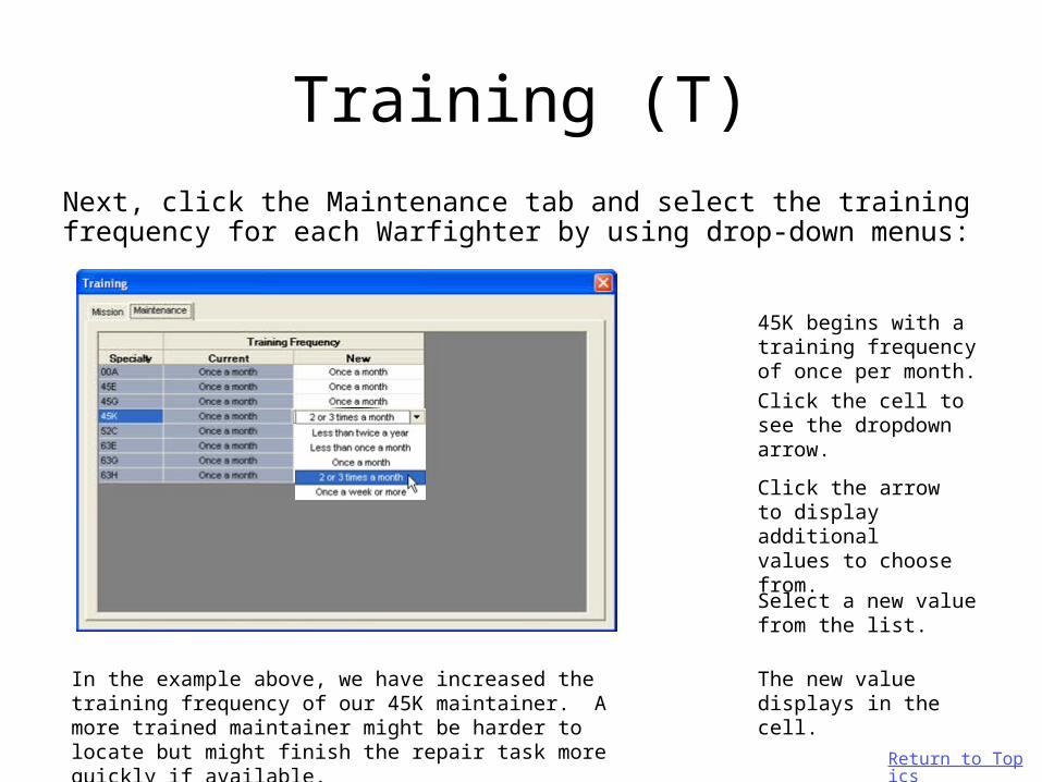
Next, click the Maintenance tab and select the training frequency for each Warfighter by using drop-down menus:
45K begins with a training frequency of once per month.
Click the cell to see the dropdown arrow.
Click the arrow to display additional values to choose from.
The new value displays in the cell.
Select a new value from the list.
In the example above, we have increased the training frequency of our 45K maintainer. A more trained maintainer might be harder to locate but might finish the repair task more quickly if available. Return to Topics
Stressors (S)
Return to Topics

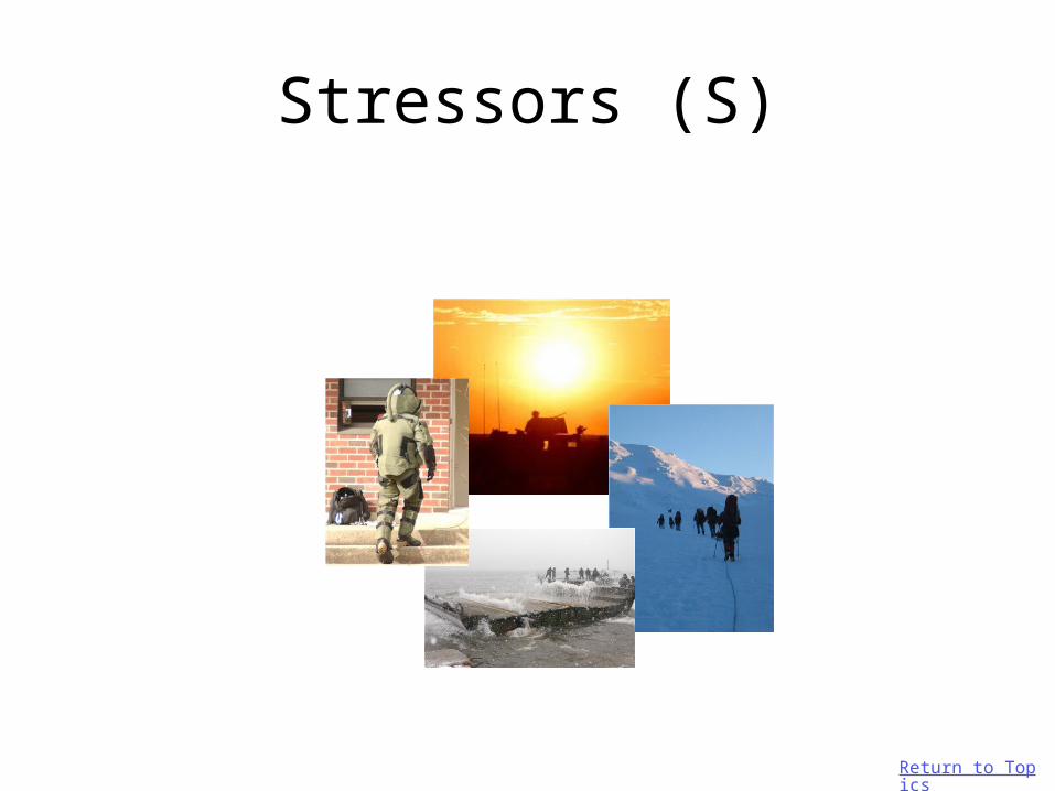
Stressors (S)
The following types of stressors may be applied to your tasks:
Cold (°F, °C)
Wind (knots)
Heat (°F, °C)
Humidity (%)
Noise (distance in ft)
Noise (decibels)
MOPP Level
Sleepless Hours
User-defined stressors
(Example: Vibration)
Return to Topics

Stressors (S)Modify the stressors in your model using the following steps:
1. Select the Moderators menu.
2. Select the Settings submenu.
3. Select the Stressors submenu.
4. The Stressors dialog box displays.
Return to Topics

Stressors (S)
Next, click the Maintenance tab and select the stressors for each Warfighter by using drop-down menus:
The task of adjust and repair of the cannon tube begins in a temperature-neutral environment.
Click the cell to see the dropdown arrow.
Click the arrow to display additional values to choose from.
The new value displays in the cell.
Select a new value from the list.
In the example above, we have decreased the temperature for our 45K maintainer. A colder environment might cause the repair task to take longer.
Return to Topics

Reviewing Moderator EffectsWith moderators now in place, review the before and after effects on repair task times as follows:
1. Select the Moderators menu.
2. Select the Results submenu.
3. The PTS Results window appears.
Return to Topics

Reviewing Moderator Effects
Review the before and after effects from your moderators as follows:
1. Scroll down and locate the cannon tube repair task.
2. Scroll to the right until you see the Time columns.
3. In the upper right-hand corner of the window, check the stressors option (to apply the cold temperatures), and then click Apply.
4. Note that the Adjusted time is approximately two minutes longer than the previous time.
Return to Topics

Checking the PTS Option
The last step in applying PTS to your model occurs when you are ready to run your model. Locate the option as follows:
1. Select the Execution menu.
2. Select the Settings Option.
3. The Execution Settings window appears.
4. Look for the PTS Adjustments checkbox on the right-hand side of this window.
5. Check the PTS Adjustments option to apply PTS moderators to your model at run-time.
Return to Topics
Running a ModelRunning a model (maintenance scenario) generates report data which may then be studied to find out how manpower estimate questions are answered by the scenario you created.
You may run your IMPRINT maintenance model at any point during the development of your model.
Return to Topics

Running a ModelRunning a model entails the following steps:
1. Checking the Execution Settings page
3. Checking for Errors
4. Begin Simulation
2. Setting the Simulation Speed
Return to Topics

Execution Settings
The Execution Settings page provides options for running your model. Access the Execution Settings page follows:
1. Locate the Execution Menu.
2. Select the Settings option.
3. The Execution Settings page appears.
Return to Topics

Execution SettingsThe Execution Settings window provides the following options for running your model:
Choose the scenario in your analysis you wish to run.
Enter the number of days you wish the scenario to run (simulation time).
Specify a random number seed to increase variability in your system repair times.
Set the number of systems you actually have available in your scenario for this run.
Check the PTS Adjustments option if you wish to use repair task times that account for personnel, training and
stressors. Check the Crew Limits On option to constrain crew to numbers specified in the shift manning levels.
Check the Animation On option to see animated system information as the model runs.
Return to Topics
Select the Maintenance Model option.

Simulation Speed
The speed of your simulation may be changed in two locations:
1. Locate the Execution menu, and then select the Simulation Speed option. In the list provided, select a new speed.
2. Locate the Simulation Speed icon on the toolbar, and select a new speed.
Return to Topics
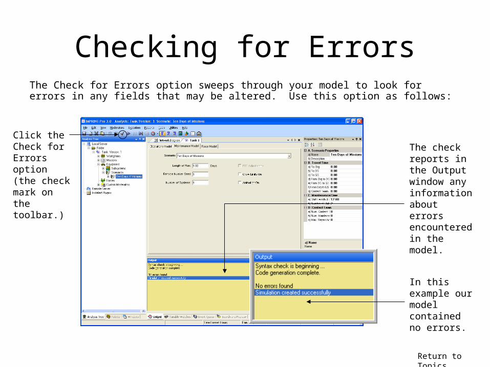
Checking for ErrorsThe Check for Errors option sweeps through your model to look for errors in any fields that may be altered. Use this option as follows:
Click the Check for Errors option (the check mark on the toolbar.)
The check reports in the Output window any information about errors encountered in the model.
In this example our model contained no errors.
Return to Topics

Begin Simulation
When you run your maintenance model, your subsystem and scenario data combines with a stochastic maintenance model included in IMPRINT Pro to provide data about the operational readiness of your scenario.
Return to Topics

Begin Simulation
You may start the run of your model in two locations:
1. Locate the Execution menu, and then select the Begin Simulation option.
2. Locate and select the Begin Simulation button on the toolbar.
Return to Topics

Begin Simulation
The Output window indicates when the model is finished running.
Running the Tank Model scenario for 10 days takes approximately 1.66 seconds to run on our machine and 240 hours to run in simulation clock time.
Return to Topics

Reports
Return to Topics

Reports
IMPRINT Pro provides 16 different reports for viewing your maintenance scenario data. Report presentations include:
Textual Summary and Detail Data
Charted Data
Return to Topics

Reports
Access the Report selection dialog for your model run as follows:
1. Locate and select the Reports menu.
2. Select the Maintenance Results option.
3. The Maintenance Results Report Selection Dialog appears.
Return to Topics

Reports
Select the reports you wish to view by checking the corresponding boxes.
Click the Check All/ Clear All options to select/deselect all reports at once.
Next, click the Ok button to view selected reports.
Return to Topics

Reports
Reports display in Microsoft Excel as worksheets in a reports workbook:
Click the tab of the report you wish to view.
The name of the report lists at the top.
Header information describing your scenario follows the report name.
Data about your model run appears in the middle.
Return to Topics

Reports
Maintenance Summary
Over the course of a 10.0 day run, systems were operating for a total of 4.0 hours.
Return to Topics

Reports
Daily Maintenance
On day 1, the Org level maintainers did a total of 1.4 hours Preventive maintenance and 30.2 hours Corrective maintenance.
Repair tasks never took place at any of the other maintenance facilities (DS, GS, Contact Team or Crew.)
Return to Topics

Reports
Reliability and Availability
Corrective maintenance tied up systems for 2.71% of the time.
.
Out of 1 segment requested, one was accomplished.
As a result our operational readiness is 100%.
Although we elected to assign 4 systems to this segment if 4 were available, only 1 system was set to go out on each departure group. With only 1 system, our segment was still accomplished.
The addition of Preventive maintenance tied up systems for 3.29% of the time
Return to Topics

Reports
Maintenance Hit Matrix
Components on the Armament subsystem required 1.25 hours Corrective Maintenance of the Remove and Replace category.
Return to Topics

Reports
Contact Team Hit Matrix and Crew Chief Hit Matrix
Because no maintenance was done by the Contact Team or the Crew, the matrix report for each contains no records.
Return to Topics

Reports
Daily Reliability
A single segment was requested and accomplished in the first day of the mission.
During the segment, four systems were requested but only one was available.
Return to Topics

Reports
Maintainability
This report shows us the average number of maintenance manhours each of the different subsystems required relative to total operating hours and total scenario hours.
Return to Topics

Reports
Maintainability
This same information is also displayed in the Maintainability graph to follow.
Return to Topics

ReportsHeadcount Frequencies
A crew size of 0 for the 45E20 specialty results in a frequency of 97.29. This means that for 97.29% of the time in this scenario run, zero (0) maintainers of this specialty were required.
For 2.19% of the time remaining, however, two (2) maintainers of this specialty were required.
This time is equal to 2.19% x 10 days x 24 hours = 5.256 hours.
The 45E20 specialty at the Org level is required but not heavily utilized.
Return to Topics

ReportsManhour Requirments
The total number of maintenance manhours performed by the 45E20 specialty at the Org level is 15.6 hours. The 63E20 specialty at the same level (Org) was utilized for slightly more time (16.0 hours).
Return to Topics

ReportsManhour Requirments
The Manhour Requirements graph displays the same information in a histogram format.
Return to Topics

Reports
Combat Damage
Out of the entire 10-day run (240 hours), only one segment lasting four (4) hours was performed.
Because the Combat parameters were not set for this scenario, this system never encountered combat hits nor any attrition or damage repair time as a result.
Return to Topics

Reports
Logistical SummaryThe wait time for spare parts among all the levels is 0.0 hours.
This can be attributed to the fact that availability of spare parts was set to 100% at the beginning of this scenario in the spares tab.
Return to Topics

Additional Resources
User Manuals:• IMPRINT Pro Volume 1: Basic Procedures• IMPRINT Pro Volume 2: Developing Analyses• IMPRINT Pro Volume 3: Syntax Reference
Quick Start Guides/Flowcharts:• IMPRINT Pro QSG - Operations Model.pdf• IMPRINT Pro QSG - Maintenance Model.pdf
For more information on IMPRINT Pro:
Return to Topics
For more information on creating IMPRINT Pro analyses, see the following resources located in the IMPRINT Pro/Documentation folder: