main bsc main ver. 7.60 bsc base station controller ver. 7 ... bss base station switch ver. 7.60 bsc...
TRANSCRIPT
TETRA
O&M Program
1
2
3
4
5
6
7
8
9
10
11
12
13
14
OM program 2001
TCC411 TX Combiner Controller ver. 2.00
PS421 Power Supply ver. 1.00
PS411 Power Supply ver. 1.00
TR421 Transceiver ver. 7.60
TR412 Transceiver ver. 7.60
API TetraFlexApi DLL ver. 7.60
BS Base Station ver. 7.60 2
BSS Base Station Switch ver. 7.60
BSC Base Station Controller ver. 7.60
MAIN BSC Main ver. 7.60
Short-form
Damm Cellular Systems A/S
Møllegade 68
DK-6400 Sønderborg,
Denmark.
Phone: +45 74423500
FAX: +45 74423330
15
16
17
18
19
20
21
22
23
24
25
26
27
28
29
30
31 Internet:
E-mail:
www.damm.dk
Licensed user:
Damm Cellular Systems A/S

Damm Cellular Systems A/S, Denmark MAIN BSC Main ver. 7.60 help
Doc. No. Rev. Date
Description
2012-11-02
MAIN BSC Main ver. 7.60 help
Functional Description
Address selection
A Display Address selection
AP Select PS421 Address
General commands
M00 Display Welcome Message
M00/A Display all software versions numbers
M00/C Display compiler options
M00/OM Display OM TCP Connection status
M01 Display Description
Alarms
M03 Display Alarm Ports
M03/OUT/n Manual Alarm Level Output Control
M03/OUT/- Stop Manual Alarm Output Control
M03/LED Display LEDs
Network Settings
M06 Display Network parameters
Date/Time
M07 Display date and time
M07/S Display date/time status
PS421 Status
M16 Display PS421 Status
M16/AL Display PS421 Alarm Flags
Debug Queue/File
Page 1 of 3Licensed user: Damm Cellular Systems A/S
Damm Cellular Systems A/S, Denmark MAIN BSC Main ver. 7.60 help
Doc. No. Rev. Date
Description
2012-11-02
M46 Display Debug Queue/File status
M46/C Clear Debug Queue
M46/S Save Debug Queue in File
GUI OM Command
M50 Display Last GUI OM Command/Response
M50/cc..c Execute GUI OM Command
CPLD
M62 Display CPLD Version
M62/HWSIG Display CPLD Hardware Signature
M62/RAM Read CPLD Test RAM
M62/RAM/hhhh Write/Read CPLD Test RAM
M62/INPORT Display Input Port
M62/ALPORT Display Alarm Port
CPU load
M66 Display CPU load
M66/C Clear CPU Load Peak Hold
M66/T Display 1msec. Timer
M66/Q Display QPC Timer
PS421 Program Download
M68 Display Program Download Status
M68/PS421 Display PS421 Program Download Status
M68/PS421/+ Start PS421 Program Download
I/O Memory
M69 Display I/O Memory Configuration
M69/hhhh/1 Read I/O Memory Byte
M69/hhhh/2 Read I/O Memory 16-bit word
M69/hhhh/hh Write I/O Memory Byte
M69/hhhh/hhhh Write I/O Memory 16-bit word
System configuration
M70 Display last File Save result
M70/SAVE Save Main Configuration
Page 2 of 3Licensed user: Damm Cellular Systems A/S
Damm Cellular Systems A/S, Denmark MAIN BSC Main ver. 7.60 help
Doc. No. Rev. Date
Description
2012-11-02
Main configurations
M71 Display Main Configuration
M71/DESCR/cc..c Change description
M71/IPADDR/ccc/... Change IP address
M71/POS/GPS/s Change Position update from GPS
M71/POS/... Change Position
M71/GPSTIME/s Change Date/Time update from GPS
PS421 configuration
M76 Display PS421 Configuration
M76/PS421 Setup PS421 configuration
M76/REMOVE Remove PS configuration
M76/PSADDR/nn Change PS421 Address
M76/BSCn/... Change BSC IP address
Factory configuration commands
M90 Display Factory Configuration status
M90/FACTORYUNLOCK Select Factory Configuration unlock
M90- Deselect Factory Configuration unlock
M90/SAVE Save Factory Configuration
Hardware Versions
M91 Display Hardware Versions
M91/ITEM/cc..c Change item number
M91/SER/cc..c Change serial number
M91/VER/n.nn Change version number
M91/REV/n Change revision number
BSC412 Factory Configuration
M92 Display BSC412 Factory Configuration
M92/GPSRX/c Change GPS RX type
Restart Commands
M99 Display command function
M99/STOP Stop BSC Service
M99/RESTART Restart BSC service
M99/UPDATE/RESTART Restart BSC service with Update
M99/BACKUP/UPDATE/RESTART Restart BSC service with Backup and Update
M99/RESTORE/RESTART Restart BSC service with Restore
Page 3 of 3Licensed user: Damm Cellular Systems A/S

Damm Cellular Systems A/S, Denmark BSC Base Station Controller ver. 7.60 help
Doc. No. Rev. Date
Description
2012-11-02
BSC Base Station Controller ver. 7.60 help
Functional Description
General commands
F00 Display Software Version
F00/BSC Display OM Red. BSC Connection status
BSC Activation Control
F02 Display BSC Activation Status
F02/ACTIVATE BSC Activation Request
F02/STANDBY/s Change Forced BSC Standby
Alarms
F03 Display BS Alarm state
F03/C Clear all BS alarms
Radio Cell Status
F13 Display Radio Cell Status
Power Supply Status
F14 Display Power Supply Status
TR Status
F15 Display TR Status
F15/c Display TR Status
F15/nn/A Display TR Alarm Flags
PS411 Status
F16 Display PS Status
F16/nn Display PS Status
F16/AL Display PS411 Alarm Flags
F16/REC Display PS411 Rectifier status
Page 1 of 3Licensed user: Damm Cellular Systems A/S
Damm Cellular Systems A/S, Denmark BSC Base Station Controller ver. 7.60 help
Doc. No. Rev. Date
Description
2012-11-02
F16/OUT Display PS411 +14V/+26V status
F16/LED Display PS411 LED status
BSS Message test queue
F63 Display BSS Link Status
F63/N Display next BSS message
F63/N+ Display next BSS message extended
F63/S Set BSS message test queue to start
F63/C Clear BSS message test queue
F63/s BSS Message suppression
F63/hh/hh..hh Send Message to BSS
UDP Message test queue
F64 Display UDP Link Status
F64/N Display next UDP message
F64/N+ Display next UDP message extended
F64/S Set UDP message test queue to start
F64/C Clear UDP message test queue
F64/s UDP Message suppression
F64/hh/hh..hh Send Message to Redundant BSC
TR Message test queue
F65 Display TR Link Status
F65/TCP Display TR TCP Connections
F65/N Display next TR message
F65/N+ Display next TR message extended
F65/S Set TR message test queue to start
F65/C Clear TR message test queue
F65/s TR Message suppression
F65/nn/hh/hh..hh Send Message to TR
BSC configuration
F70 Display last File Save result
F70/SAVE Save BSC Configuration
System configurations
F71 Display Common Configurations
F71/CNFG/+ Activate BSC
F71/CNFG/- Deactivate BSC
F71/BSCNO/n Change BSC Number
F71/REDBSC/s Change Redundant BSC Selection
F71/REDBSC/... Change Redundant BSC IP Address
Page 2 of 3Licensed user: Damm Cellular Systems A/S

Damm Cellular Systems A/S, Denmark BSC Base Station Controller ver. 7.60 help
Doc. No. Rev. Date
Description
2012-11-02
F71/BSS/... Change BSS IP Address
F71/BSS/nnnnn Change BSS Remote Port
F71/BSS/c Change BSS Message Protocol
TR Configuration
F75 Display TR Configuration
F75/nn/TR412 Add TR412 Transceiver
F75/nn/TR421 Add TR421 Transceiver
F75/nn/REMOVE Remove TR
PS Configuration
F76 Display PS Configuration
F76/nn/PS411 Add PS411 Power Supply
F76/nn/PS421 Add PS421 Power Supply
F76/nn/REMOVE Remove PS
Page 3 of 3Licensed user: Damm Cellular Systems A/S
Damm Cellular Systems A/S, Denmark BSS Base Station Switch ver. 7.60 help
Doc. No. Rev. Date
Description
2012-11-02
BSS Base Station Switch ver. 7.60 help
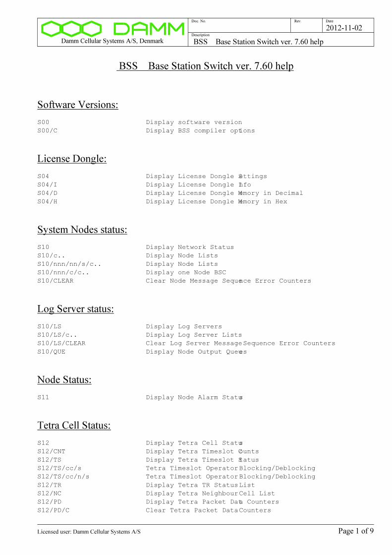
Software Versions:
S00 Display software version
S00/C Display BSS compiler options
License Dongle:
S04 Display License Dongle Settings
S04/I Display License Dongle Info
S04/D Display License Dongle Memory in Decimal
S04/H Display License Dongle Memory in Hex
System Nodes status:
S10 Display Network Status
S10/c.. Display Node Lists
S10/nnn/nn/s/c.. Display Node Lists
S10/nnn/c/c.. Display one Node BSC
S10/CLEAR Clear Node Message Sequence Error Counters
Log Server status:
S10/LS Display Log Servers
S10/LS/c.. Display Log Server Lists
S10/LS/CLEAR Clear Log Server Message Sequence Error Counters
S10/QUE Display Node Output Queues
Node Status:
S11 Display Node Alarm Status
Tetra Cell Status:
S12 Display Tetra Cell Status
S12/CNT Display Tetra Timeslot Counts
S12/TS Display Tetra Timeslot Status
S12/TS/cc/s Tetra Timeslot Operator Blocking/Deblocking
S12/TS/cc/n/s Tetra Timeslot Operator Blocking/Deblocking
S12/TR Display Tetra TR Status List
S12/NC Display Tetra Neighbour Cell List
S12/PD Display Tetra Packet Data Counters
S12/PD/C Clear Tetra Packet Data Counters
Page 1 of 9Licensed user: Damm Cellular Systems A/S
Damm Cellular Systems A/S, Denmark BSS Base Station Switch ver. 7.60 help
Doc. No. Rev. Date
Description
2012-11-02
S12/CCK/c Tetra CCK change request
Voice Gateway Status:
S13 Display Voice Gateway Status
S13/L Display Voice Gateway Status List
S13/nnn Display Voice Gateway Instance Status
Packet Data Gateway Status:
S14 Display Packet Data Gateway Status
S14/N Display Packet Data Gateway Counters
S14/C Clear Packet Data Gateway Counters
Application Gateway Status:
S15 Display Application Gateway Status
S15/L Display Application Gateway Connection List
S15/IX/nnn Display Application Gateway Connection (Index)
S15/SSI/nnnnnnnn Display Application Gateway Instance (SSI)
S15/USERNO/nn..n Display Application Gateway Connection (User
Number)
Terminal Gateway Status:
S16 Display Terminal Gateway Status
S16/L Display Terminal Gateway Connection List
S16/IX/nnn Display Terminal Gateway Connection (Index)
S16/SSI/nnnnnnnn Display Terminal Gateway Connection (SSI)
S16/USERNO/nn..n Display Terminal Gateway Connection (User Number)
Subscriber Register:
S20 Display Subscriber Register
S20/S Display Subscriber Register Status
S20/CNT Display Subscriber Register Counts
S20/CKS Display Subscriber Register Checksums
S20/DL Display Master Subscriber Register Download status
S20/REG Display Subscriber Registration Update status
S20/REG/+ Start Subscriber Registration Update
S20/TEI/nnn..n Find TEI Terminal Equipment Identity
S20/SIM/nnn..n Find SIM Card Identity
S20/SECSET Display Security Set Renew Status
S20/SECSET/RENEW Start Security Set Renewal
S20/SAVE Save Subscriber Register to OM command file
S20/READ Read Subscriber Register from OM command file
S20/CHECK Subscriber Register consistency check
Page 2 of 9Licensed user: Damm Cellular Systems A/S
Damm Cellular Systems A/S, Denmark BSS Base Station Switch ver. 7.60 help
Doc. No. Rev. Date
Description
2012-11-02
S20/QUE Display Subscriber Register queues
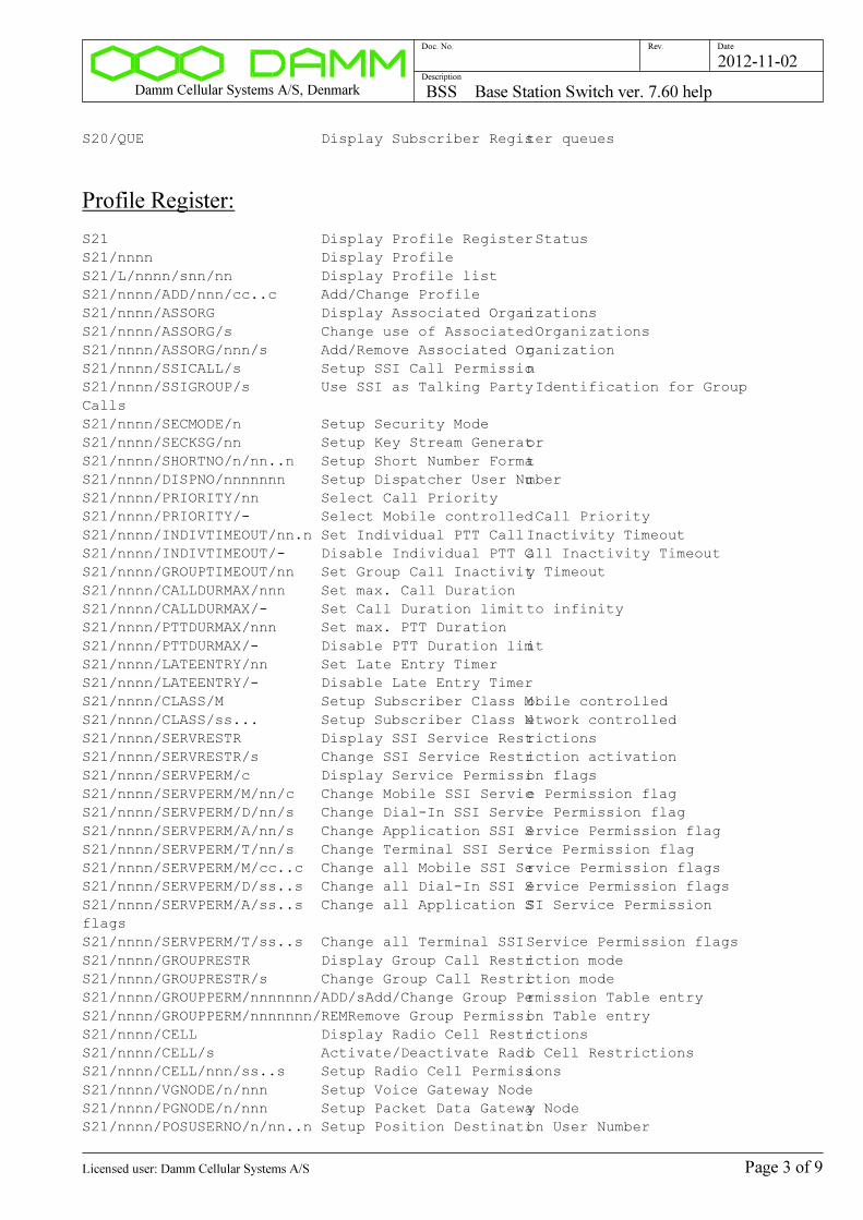
Profile Register:
S21 Display Profile Register Status
S21/nnnn Display Profile
S21/L/nnnn/snn/nn Display Profile list
S21/nnnn/ADD/nnn/cc..c Add/Change Profile
S21/nnnn/ASSORG Display Associated Organizations
S21/nnnn/ASSORG/s Change use of Associated Organizations
S21/nnnn/ASSORG/nnn/s Add/Remove Associated Organization
S21/nnnn/SSICALL/s Setup SSI Call Permission
S21/nnnn/SSIGROUP/s Use SSI as Talking Party Identification for Group
Calls
S21/nnnn/SECMODE/n Setup Security Mode
S21/nnnn/SECKSG/nn Setup Key Stream Generator
S21/nnnn/SHORTNO/n/nn..n Setup Short Number Format
S21/nnnn/DISPNO/nnnnnnn Setup Dispatcher User Number
S21/nnnn/PRIORITY/nn Select Call Priority
S21/nnnn/PRIORITY/- Select Mobile controlled Call Priority
S21/nnnn/INDIVTIMEOUT/nn.n Set Individual PTT Call Inactivity Timeout
S21/nnnn/INDIVTIMEOUT/- Disable Individual PTT Call Inactivity Timeout
S21/nnnn/GROUPTIMEOUT/nn Set Group Call Inactivity Timeout
S21/nnnn/CALLDURMAX/nnn Set max. Call Duration
S21/nnnn/CALLDURMAX/- Set Call Duration limit to infinity
S21/nnnn/PTTDURMAX/nnn Set max. PTT Duration
S21/nnnn/PTTDURMAX/- Disable PTT Duration limit
S21/nnnn/LATEENTRY/nn Set Late Entry Timer
S21/nnnn/LATEENTRY/- Disable Late Entry Timer
S21/nnnn/CLASS/M Setup Subscriber Class Mobile controlled
S21/nnnn/CLASS/ss... Setup Subscriber Class Network controlled
S21/nnnn/SERVRESTR Display SSI Service Restrictions
S21/nnnn/SERVRESTR/s Change SSI Service Restriction activation
S21/nnnn/SERVPERM/c Display Service Permission flags
S21/nnnn/SERVPERM/M/nn/c Change Mobile SSI Service Permission flag
S21/nnnn/SERVPERM/D/nn/s Change Dial-In SSI Service Permission flag
S21/nnnn/SERVPERM/A/nn/s Change Application SSI Service Permission flag
S21/nnnn/SERVPERM/T/nn/s Change Terminal SSI Service Permission flag
S21/nnnn/SERVPERM/M/cc..c Change all Mobile SSI Service Permission flags
S21/nnnn/SERVPERM/D/ss..s Change all Dial-In SSI Service Permission flags
S21/nnnn/SERVPERM/A/ss..s Change all Application SSI Service Permission
flags
S21/nnnn/SERVPERM/T/ss..s Change all Terminal SSI Service Permission flags
S21/nnnn/GROUPRESTR Display Group Call Restriction mode
S21/nnnn/GROUPRESTR/s Change Group Call Restriction mode
S21/nnnn/GROUPPERM/nnnnnnn/ADD/sAdd/Change Group Permission Table entry
S21/nnnn/GROUPPERM/nnnnnnn/REMRemove Group Permission Table entry
S21/nnnn/CELL Display Radio Cell Restrictions
S21/nnnn/CELL/s Activate/Deactivate Radio Cell Restrictions
S21/nnnn/CELL/nnn/ss..s Setup Radio Cell Permissions
S21/nnnn/VGNODE/n/nnn Setup Voice Gateway Node
S21/nnnn/PGNODE/n/nnn Setup Packet Data Gateway Node
S21/nnnn/POSUSERNO/n/nn..n Setup Position Destination User Number
Page 3 of 9Licensed user: Damm Cellular Systems A/S

Damm Cellular Systems A/S, Denmark BSS Base Station Switch ver. 7.60 help
Doc. No. Rev. Date
Description
2012-11-02
S21/nnnn/DNS/... Setup DNS Server IP Address
S21/nnnn/DEL Delete Profile
Subscriber Register SSI:
S22 Display SSI Register Status
S22/nnnnnnnn Display SSI
S22/L/nnnnnnnn/snn/nn Display SSI list
S22/nnnnnnnn/REG Display SSI Registration
S22/nnnnnnnn/REG/GROUP Display SSI Attached Groups
S22/TSI/... Display TSI
S22/TSI/.../L Display TSI Chain List
S22/TSICHAIN/nnnnnn Display TSI Chain List
S22/TSIIXTB Display TSI Indax Table
S22/nnnnnnnn/ADD/c/... Add/Change SSI
S22/nnnnnnnn/ADD/c/... Add/Change SSI
S22/nnnnnnnn/DESCR/... Setup SSI Description
S22/nnnnnnnn/TSI/... Setup Visiting TSI
S22/nnnnnnnn/TSI/- Clear Visiting TSI
S22/nnnnnnnn/BLOCK/s Change SSI Blocking
S22/nnnnnnnn/PINCODE/cc..c Change PIN Code
S22/nnnnnnnn/TEI/... Setup TEI Terminal Equipment Identity
S22/nnnnnnnn/TEI/- Clear TEI Terminal Equipment Identity
S22/nnnnnnnn/SIM/... Setup SIM ID
S22/nnnnnnnn/SIM/- Clear SIM ID
S22/nnnnnnnn/AUTHDIS/s Change Mobile Authentication Disable Flag
S22/nnnnnnnn/AIEDIS/s Change Air Interface Encryption Disable Flag
S22/nnnnnnnn/SECSET/R Renew Security Set from Security Key
S22/nnnnnnnn/SECSET/... Setup Security Set
S22/nnnnnnnn/SECSET/C Clear Security Set
S22/nnnnnnnn/GROUPTEXT/cc..cSetup Group Text Line
S22/nnnnnnnn/GROUPINCL Display Group Include Table
S22/nnnnnnnn/GROUPINCL/s Enable/Disable Group Include Table
S22/nnnnnnnn/GROUPINCL/nnnnnnn/ADDAdd/Change Group Include Table entry
S22/nnnnnnnn/GROUPINCL/nnnnnnn/REMRemove Group Include Table entry
S22/nnnnnnnn/CALLTRF/c Change Call Transfer
S22/nnnnnnnn/CALLTRFNO/cc..cChange Call Transfer Number
S22/nnnnnnnn/CALLTRFTIME/nnChange Call Transfer delay time
S22/nnnnnnnn/SUBREG/s Change Subscriber Register change permission
S22/nnnnnnnn/DISCREETLIST/sChange Discreet Listening permission
S22/nnnnnnnn/AMBIENCELIST/sChange Ambience Listening permission
S22/nnnnnnnn/TEMPENDIS/s Change Temporary Mobile Enable/Disable permission
S22/nnnnnnnn/PERMDIS/s Change Permanent Mobile Disable permission
S22/nnnnnnnn/GROUPMAN/s Change Mobile Group Management permission
S22/nnnnnnnn/NUMBERMOD/s Change Number Modification Permission
S22/nnnnnnnn/EMERGPRI/nn Change Emergency Number Call Priority
S22/nnnnnnnn/TARGET Display Target Table
S22/nnnnnnnn/TARGET/c Display Targets
S22/nnnnnnnn/TARGET/n/c/c/c/cc..cAdd/Change/Remove Target
S22/nnnnnnnn/DEL Delete SSI
Page 4 of 9Licensed user: Damm Cellular Systems A/S
Damm Cellular Systems A/S, Denmark BSS Base Station Switch ver. 7.60 help
Doc. No. Rev. Date
Description
2012-11-02
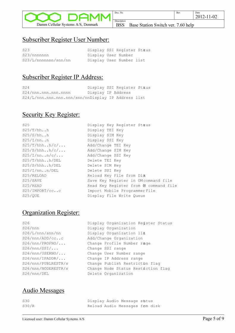
Subscriber Register User Number:
S23 Display SSI Register Status
S23/nnnnnnn Display User Number
S23/L/nnnnnnn/snn/nn Display User Number list
Subscriber Register IP Address:
S24 Display SSI Register Status
S24/nnn.nnn.nnn.nnnn Display IP Address
S24/L/nnn.nnn.nnn.nnn/snn/nnDisplay IP Address list
Security Key Register:
S25 Display Key Register Status
S25/T/hh..h Display TEI Key
S25/S/hh..h Display SIM Key
S25/I/nn..n Display SSI Key
S25/T/hhh..h/c/... Add/Change TEI Key
S25/S/hhh..h/c/... Add/Change SIM Key
S25/I/nn..n/c/... Add/Change SSI Key
S25/T/hhh..h/DEL Delete TEI Key
S25/S/hhh..h/DEL Delete SIM Key
S25/I/nn..n/DEL Delete SSI Key
S25/RELOAD Reload Key File from Disk
S25/SAVE Save Key Register in OM command file
S25/READ Read Key Register from OM command file
S25/IMPORT/cc..c Import Mobile Programmer File
S25/QUE Display File Write Queue
Organization Register:
S26 Display Organization Register Status
S26/nnn Display Organization
S26/L/nnn/snn/nn Display Organization list
S26/nnn/ADD/cc..c Add/Change Organization
S26/nnn/PROFNO/... Change Profile Number range
S26/nnn/SSI/... Change SSI range
S26/nnn/USERNO/... Change User Number range
S26/nnn/IPADDR/... Change IP Address range
S26/nnn/PUBLRESTR/s Change Publish Restriction flag
S26/nnn/NODERESTR/s Change Node Status Restriction flag
S26/nnn/DEL Delete Organization
Audio Messages
S30 Display Audio Message status
S30/R Reload Audio Messages from disk
Page 5 of 9Licensed user: Damm Cellular Systems A/S
Damm Cellular Systems A/S, Denmark BSS Base Station Switch ver. 7.60 help
Doc. No. Rev. Date
Description
2012-11-02
TetraFlex Shares
S31 Display TetraFlex Shares
S31/nn Display TetraFlex Share
S31/nn/nnnn-nn-nn Change Version Date
InterNode OM Command
S50 Display Command function
S50/D Display last received OM Command/Response
S50/ccc/cc..c Send OM Command to other Node(s)
Application Gateway Subscriber Register Command
S51 Display Command function
S51/D Display last API Command/Response
S51/nnnnnnnn/cc..c Execute API Command
Log Server Message test queue:
S64 Display Log Server Connection Status
S64/N Display next Log Server message
S64/N+ Display next Log Server message extended
S64/S Set Log Server message test queue to start
S64/C Clear Log Server message test queue
S64/s Log Server Message suppression
S64/hh/hh..hh Send message to Home Log Servers
S64/nnn.nnn.nnn.nnn/hh/hh..hhSend message to Log Servers
Internode Control Message test queue:
S65 Display Internode Connection status
S65/N Display next Internode Control Message
S65/N+ Display next Internode Control Message extended
S65/S Set Internode Control Message test queue to start
S65/C Clear Internode Control Message test queue
S65/s Internode Control Message suppression
S65/ALL/hh/hh..hh Send Control Message to all Nodes
S65/SD/hh/hh..hh Send Control Message to Subscriber Register
Download Nodes
S65/DL/hh/hh..hh Send Control Message to Discreet Listening Nodes
S65/nnn/hh/hh..hh Send Control Message to specific Node
S65/nnn.nnn.nnn.nnn/hh/hh..hhSend Control Message to specific IP Address
Page 6 of 9Licensed user: Damm Cellular Systems A/S

Damm Cellular Systems A/S, Denmark BSS Base Station Switch ver. 7.60 help
Doc. No. Rev. Date
Description
2012-11-02
BSS Configuration Commands:
S70 Display last file save result
S70/SAVE Save BSS Configuration
General Node configuration:
S71 Display General Node configuration
S71/NODENO/nnn Change Node Number
S71/IP/MCADDR/... Change Multicast Base IP Address
S71/IP/MCPORT/nnnnn Change Control Multicast Port Number
S71/IP/UCPORT/nnnnn Change Control Unicast Port Number
S71/IP/LOGADDR/... Change Log Multicast IP Address
S71/IP/LOGPORT/nnnnn Change Log UDP Port Number
S71/IP/CMOIPADDR/... Change CMoIP Multicast IP Address
S71/MCC/nnnn Change Mobile Country Code
S71/MNC/nnnnn Change Mobile Network Code
S71/NODETIMEOUT/nnnn Change Inter-node Timeout
S71/MULTIVOCODER/s Change Multivocoder selection
S71/VOICEBUF/n Change Voice Buffer length
S71/SUBIPADDR/... Change Subscriber IP Address Segment
S71/SUBMODE/c Change Subscriber Register Mode
S71/KEYREG/s Key Register activation
S71/SHARENAME/cc..c Share Name
S71/SHAREUSER/cc..c Share User
S71/SHAREPASSWORD/cc..c Share Password
S71/TR Display TR Use
S71/TR/nn/s Change TR Use
Tetra Cell Configuration:
S72 Display Tetra Cell configuration
S72/CNFG/+ Activate Tetra Cell
S72/CNFG/- Deactivate Tetra Cell
S72/BSPWR/+nn.n Change Tetra BS Output Power
S72/BSPWR/- Set Tetra BS Output Power to TR Controlled
S72/BSPWR/RED/+nn.n Change Tetra BS Reduced Output Power
S72/BSPWR/RED/- Set Tetra BS Reduced Output Power to TR Controlled
S72/BSPWR/RED/N Set Tetra BS Reduced Output Power to Normal
S72/SCCH/n Change number of SCCH to setup
S72/PDCH/nn Change minimum number of PDCH
S72/FALLBACK/s Change Fallback Mode Indication
S72/MSPWR/n Change max. MS TX Power
S72/MSACC/nn Change min. MS RX Access Level
S72/ACCPAR/nn Radio Access Parameter
S72/DLTO/nn Change Radio Downlink Timeout
Page 7 of 9Licensed user: Damm Cellular Systems A/S
Damm Cellular Systems A/S, Denmark BSS Base Station Switch ver. 7.60 help
Doc. No. Rev. Date
Description
2012-11-02
S72/CONNTIMEOUT/n Change Connection Timeout
S72/CLASS/ss... Change Subscriber Class
S72/AIE/s Change Air Interface Encryption activation
S72/NCSYNC/c Change Neighbour Cell Synchronization
S72/SRT/nn Change Slow Reselect Threshold above Fast
S72/FRT/nn Change Fast Reselect Threshold
S72/SRH/nn Change Slow Reselect Hysteresis
S72/FRH/nn Change Fast Reselect Hysteresis
S72/TR Display Tetra TR Configuration
S72/TR/AUTO/s Change Tetra Auto Convert Flag
S72/TR/BI/nn/n/n/s Change Tetra Band Info for all TR
S72/TR/nn/FREQ/... Change Tetra TR Frequencies
S72/TR/nn/BI/... Change Tetra TR Band Info
S72/TR/nn/CN/... Change Tetra TR Carrier Number
S72/NC Display Tetra Neighbour Cell configuration list
S72/NC/+ Activate Tetra Neighbour Cell configuration list
S72/NC/- De-activate Tetra Neighbour Cell List
S72/NC/nnn/+ Add Tetra Neighbour Cell to list
S72/NC/nnn/- Remove Tetra Neighbour Cell from list
Voice Gateway configuration:
S73 Display Voice Gateway configuration
S73/CNFG/+ Activate Voice Gateway
S73/CNFG/- Deactivate Voice Gateway
S73/ORG/ccc Change Voice Gateway Organization Number
S73/CALLMAX/nnn Change max. number of Voice Gateway calls
S73/PRIORITY/nn Change PABX->Tetra Call Priority
S73/REG/s Change Voice Gateway Registration Selection
S73/NAME/cc..c Change Voice Gateway Registration Name
S73/PASSWORD/cc..c Change Voice Gateway Registration Name
S73/IPADDR/... Change Voice Gateway Remote IP Address
S73/PORT/LOC/nnnnn Change Voice Gateway Local IP Port
S73/PORT/REM/nnnnn Change Voice Gateway Remote IP Port
Packet Data Gateway configuration:
S74 Display Packet Data Gateway configuration
S74/CNFG/+ Activate Packet Data Gateway
S74/CNFG/- Deactivate Packet Data Gateway
S74/RIP/s Change Packet Data Gateway RIP selection
Application Gateway configuration:
S75 Display Application Gateway configuration
S75/CNFG/+ Activate Application Gateway
S75/CNFG/- Deactivate Application Gateway
S75/CONNMAX/nnn Change max. Application Gateway connections
S75/STREAMMAX/nnn Change max. Application Gateway Circuit Mode
Streams
Page 8 of 9Licensed user: Damm Cellular Systems A/S
Damm Cellular Systems A/S, Denmark BSS Base Station Switch ver. 7.60 help
Doc. No. Rev. Date
Description
2012-11-02
S75/CONNTIMEOUT/nnn Connection Timeout
S75/DISCRLIST/s Change Application Gateway Discreet Listening
Terminal Gateway configuration:
S76 Display Terminal Gateway configuration
S76/CNFG/+ Activate Terminal Gateway
S76/CNFG/- Deactivate Terminal Gateway
S76/CONNMAX/nnn Change max. Terminal Gateway connections
S76/STREAMMAX/nnn Change max. Terminal Gateway Circuit Mode Streams
S76/CONNTIMEOUT/nnn Connection Timeout
Page 9 of 9Licensed user: Damm Cellular Systems A/S

Damm Cellular Systems A/S, Denmark BS Base Station ver. 7.60 help
Doc. No. Rev. Date
Description
2012-11-02
BS Base Station ver. 7.60 help
Functional Description
BS Address selection
BSC41x UART Address selection
AU Display BSC41x UART selection
AU+ Select BSC41x UART Address
AU- Deselect BSC41x UART Address
AU/FORCED Forced BSC41x UART Address select
Device Address selection
A Display Address
Ann Select BS41x TR Address
APnn Select BS41x PS Address
ATnn Select BS41x TC Address
Software Version:
H00 Display software version
H00/A Display all software version numbers
H00/C Display compiler options
H00/OM Display OM TCP Connection status
H00/BSC Display OM BSC Connection status
BS Activation Control
H02 Display BS Activation Status
H02/ACTIVATE BS Activation Request
H02/STANDBY/s Change Forced BSC Standby
Alarms
H03 Display BS Alarm state
H03/A Display BSC Alarm Flags
H03/IN Display Alarm Inputs
Page 1 of 5Licensed user: Damm Cellular Systems A/S

Damm Cellular Systems A/S, Denmark BS Base Station ver. 7.60 help
Doc. No. Rev. Date
Description
2012-11-02
Synchronization Status
H12 Display Synchronization Status
H12/IN Display Sync Inputs
H12/MASTER Display Master Table
H12/PPS Display 1PPS Inputs
H12/HIST Display OCXO Sync History
BS Antenna Status
H13 Display Radio Cell Antenna Status
TR Status
H15 Display TR Status
H15/c Display TR Status
H15/nn/A Display TR Alarm Flags
PS Status
H16 Display PS Status
H16/AL Display PS411 Alarm Flags
H16/REC Display PS411 Rectifier status
H16/OUT Display PS411 +14V/+26V status
H16/LED Display PS411 LED status
H16/nn Display PS411 Status
OCXO:
H31 Display OCXO Sync
H31/IN/c Change Sync Input selection
H31/SET Set OCXO Free Run adjust value to current DAC
value
H31/SET/nn.nnn Set OCXO Free Run value
H31/SAVE Save OCXO Free Run adjust value in Flash
H31/STEP/nn.nnn Simulate a PLL Frequency Step
Internal GPS RX:
H32 Display Internal GPS RX Status
H32/VER Display GPS Module Version
H32/N Display next Internal GPS message
H32/SETUP Setup GPS RX Module
H32/SEND/cc..c Send Command to GPS RX Module
Page 2 of 5Licensed user: Damm Cellular Systems A/S

Damm Cellular Systems A/S, Denmark BS Base Station ver. 7.60 help
Doc. No. Rev. Date
Description
2012-11-02
CMoIP Switch
H34 Display all CMoIP Connections
H34/nn/n Display one CMoIP Connection
H34/nn/n/... CMoIP Multicast Connect
H34/nn/n/REL CMoIP Multicast Release
H34/C Clear Message Counters
Message Trace:
H48 Display Message Trace
H48- Stop all Message Traces
H48/C Clear Trace Counters
H48/UDP/+ Activate Trace output to UDP
H48/UDP/- Stop Trace output to UDP
H48/UDP/nnn... Change Trace UDP address+port
H48/FILE/+ Open Trace output file
H48/FILE/- Close Trace output file
H48/FILE/cc..c Change Trace filename
H48/n/s Start/Stop Trace
H48/n/nn/n/c Setup Trace Test Point
Tetra Channel Test:
H49 Display Tetra channel test selection
H49/c Change Sync Mode
H49/n Change Sync Output Frequency
H49/nn/n/nn Select Logical Channel to evaluate
H49/CNTR Display Counters
H49/CLEAR Clear Counter Values
H49/DATA Display data from TR
DC Voltmeter
H60 Display DC Voltmeter
Co-Processor
H61 Display Co-Processor Status
H61/Fhhh0 Display DPRAM
H61/MEM/hhhhh Read CP Memory
H61/PORT/hhhhh Read CP Port
BS<->BSC Message test queue
H63 Display BSC Link Status
Page 3 of 5Licensed user: Damm Cellular Systems A/S
Damm Cellular Systems A/S, Denmark BS Base Station ver. 7.60 help
Doc. No. Rev. Date
Description
2012-11-02
H63/N Display next BSC message
H63/N+ Display next BSC message extended
H63/S Set BSC message test queue to start
H63/C Clear BSC message test queue
H63/s BSC Message suppression
H63/n/hh/hh..hh Send Message to BSC
UDP Message test queue
H64 Display UDP Link Status
H64/N Display next UDP message
H64/N+ Display next UDP message extended
H64/S Set UDP message test queue to start
H64/C Clear UDP message test queue
H64/s UDP Message suppression
H64/hh/hh..hh Send Message to Redundant BS
BS<->TR Message test queue
H65 Display TR Link Status
H65/PS Display PS411 Link Status
H65/N Display next TR message
H65/N+ Display next TR message extended
H65/S Set TR message test queue to start
H65/C Clear TR message test queue
H65/s TR Message suppression
H65/nn/hh/hh..hh Send Message to TR
H65/PS/nn/hh/hh..hh Send Message to PS411
Program Download
H68 Display Program Download Status
H68/TR412 Display TR412 Program Download Status
H68/TR412/cc TR412 Program Download command
BS configuration:
H70 Display command function
H70/SAVE Save BS configuration in file
Common system configuration:
H71 Display Common BS configuration
H71/CNFG/+ Activate BS
H71/CNFG/- Deactivate BS
H71/BSNO/n Change BS Number
H71/RACKNO/n Change Rack Number
Page 4 of 5Licensed user: Damm Cellular Systems A/S

Damm Cellular Systems A/S, Denmark BS Base Station ver. 7.60 help
Doc. No. Rev. Date
Description
2012-11-02
H71/REDBS/s Change Redundant BS Configuration
H71/REDBS/... Change Redundant BS IP Address
H71/BSC/n/s Change BSC Configuration
H71/BSC/n/nnn.nnn.nnn.nnn Change BSC IP Address
H71/CMOIP Display CMoIP selection
H71/CMOIP/s Change CMoIP selection
H71/CMOIP/n/... Change CMoIP BSS IP Address
Synchronization configurations
H72 Display BSC412 Sync selection
H72/MASTER/c Change Master Priority
H72/CENTSECOFS/snnnnnnnnnn Change Century Second offset
H72/CENTSECOFS/DAMM Change Century Second offset to DAMM
H72/CENTSECOFS/EADS Change Century Second offset to EADS
H72/GPSRXOFS/snnn.n Change GPS RX offset
H72/GPSRXOFS/DAMM Change GPS RX offset to DAMM
H72/GPSRXOFS/EADS Change GPS RX offset to EADS
H72/IN/n/s Activate/Deactivate BSC412 Sync Input
H72/IN/n/... Setup BSC412 External Sync Input
H72/OUT Display BSC412 Sync Message Output Table
H72/OUT/... Add/Remove BSC412 Sync Message Output
Radio Cell configuration
H73 Display Radio Cell configuration
H73/RXDIV/c Change RX Diversity configuration
H73/RXPREGAIN/n.n Change RX Pre-Gain
H73/RXBAND/... Change RX frequency band
H73/TXBAND/... Change TX frequency band
H73/TXANT/... Change TX antenna alarm settings
Power Supply configuration
H74 Display PS411 Power Supply configuration
H74/AC/s Change PS411 AC Input selection
H74/CHARGE/s Change PS411 Battery Charging selection
H74/CHGVOLT/nn.n Change PS411 Charging Voltage
H74/CHGCOMP/nnn Change PS411 Charging Compensation
Page 5 of 5Licensed user: Damm Cellular Systems A/S
Damm Cellular Systems A/S, Denmark API TetraFlexApi DLL ver. 7.60 help
Doc. No. Rev. Date
Description
2012-11-02
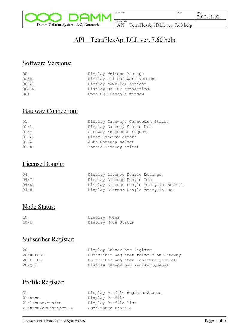
API TetraFlexApi DLL ver. 7.60 help
Software Versions:
00 Display Welcome Message
00/A Display all software versions
00/C Display compiler options
00/OM Display OM TCP connections
00+ Open GUI Console Window
Gateway Connection:
01 Display Gateways Connection Status
01/L Display Gateway Status List
01/+ Gateway reconnect request
01/C Clear Gateway errors
01/A Auto Gateway select
01/n Forced Gateway select
License Dongle:
04 Display License Dongle Settings
04/I Display License Dongle Info
04/D Display License Dongle Memory in Decimal
04/H Display License Dongle Memory in Hex
Node Status:
10 Display Nodes
10/c Display Node Status
Subscriber Register:
20 Display Subscriber Register
20/RELOAD Subscriber Register reload from Gateway
20/CHECK Subscriber Register consistency check
20/QUE Display Subscriber Register Queues
Profile Register:
21 Display Profile Register Status
21/nnnn Display Profile
21/L/nnnn/snn/nn Display Profile list
21/nnnn/ADD/nnn/cc..c Add/Change Profile
Page 1 of 5Licensed user: Damm Cellular Systems A/S

Damm Cellular Systems A/S, Denmark API TetraFlexApi DLL ver. 7.60 help
Doc. No. Rev. Date
Description
2012-11-02
21/nnnn/ASSORG Display Associated Organizations
21/nnnn/ASSORG/s Change use of Associated Organizations
21/nnnn/ASSORG/nnn/s Add/Remove Associated Organization
21/nnnn/SSICALL/s Setup SSI Call Permission
21/nnnn/SSIGROUP/s Use SSI as Talking Party Identification for Group
Calls
21/nnnn/SECMODE/n Setup Security Mode
21/nnnn/SECKSG/nn Setup Key Stream Generator
21/nnnn/SHORTNO/n/nn..n Setup Short Number Format
21/nnnn/DISPNO/nnnnnnn Setup Dispatcher User Number
21/nnnn/PRIORITY/nn Select Call Priority
21/nnnn/PRIORITY/- Select Mobile controlled Call Priority
21/nnnn/INDIVTIMEOUT/nn.n Set Individual PTT Call Inactivity Timeout
21/nnnn/INDIVTIMEOUT/- Disable Individual PTT Call Inactivity Timeout
21/nnnn/GROUPTIMEOUT/nn Set Group Call Inactivity Timeout
21/nnnn/CALLDURMAX/nnn Set max. Call Duration
21/nnnn/CALLDURMAX/- Set Call Duration limit to infinity
21/nnnn/PTTDURMAX/nnn Set max. PTT Duration
21/nnnn/PTTDURMAX/- Disable PTT Duration limit
21/nnnn/LATEENTRY/nn Set Late Entry Timer
21/nnnn/LATEENTRY/- Disable Late Entry Timer
21/nnnn/CLASS/M Setup Subscriber Class Mobile controlled
21/nnnn/CLASS/ss... Setup Subscriber Class Network controlled
21/nnnn/SERVRESTR Display SSI Service Restrictions
21/nnnn/SERVRESTR/s Change SSI Service Restriction activation
21/nnnn/SERVPERM/c Display Service Permission flags
21/nnnn/SERVPERM/M/nn/c Change Mobile SSI Service Permission flag
21/nnnn/SERVPERM/D/nn/s Change Dial-In SSI Service Permission flag
21/nnnn/SERVPERM/A/nn/s Change Application SSI Service Permission flag
21/nnnn/SERVPERM/T/nn/s Change Terminal SSI Service Permission flag
21/nnnn/SERVPERM/M/cc..c Change all Mobile SSI Service Permission flags
21/nnnn/SERVPERM/D/ss..s Change all Dial-In SSI Service Permission flags
21/nnnn/SERVPERM/A/ss..s Change all Application SSI Service Permission
flags
21/nnnn/SERVPERM/T/ss..s Change all Terminal SSI Service Permission flags
21/nnnn/GROUPRESTR Display Group Call Restriction mode
21/nnnn/GROUPRESTR/s Change Group Call Restriction mode
21/nnnn/GROUPPERM/nnnnnnn/ADD/s/sAdd/Change Group Permission Table entry
21/nnnn/GROUPPERM/nnnnnnn/REMRemove Group Permission Table entry
21/nnnn/CELL Display Radio Cell Restrictions
21/nnnn/CELL/s Activate/Deactivate Radio Cell Restrictions
21/nnnn/CELL/nnn/ss..s Setup Radio Cell Permissions
21/nnnn/VGNODE/n/nnn Setup Voice Gateway Node
21/nnnn/PGNODE/n/nnn Setup Packet Data Gateway Node
21/nnnn/POSUSERNO/n/nn..n Setup Position Destination User Number
21/nnnn/DNS/... Setup DNS Server IP Address
21/nnnn/DEL Delete Profile
Subscriber Register SSI:
22 Display SSI Register Status
22/nnnnnnnn Display SSI
22/L/nnnnnnnn/snn/nn Display SSI list
Page 2 of 5Licensed user: Damm Cellular Systems A/S

Damm Cellular Systems A/S, Denmark API TetraFlexApi DLL ver. 7.60 help
Doc. No. Rev. Date
Description
2012-11-02
22/nnnnnnnn/REG Display SSI Registration
22/nnnnnnnn/REG/GROUP Display SSI Attached Groups
22/TSI/... Display TSI
22/TSI/.../L Display TSI Chain List
22/TSICHAIN/nnnnnn Display TSI Chain List
22/TSIIXTB Display TSI Indax Table
22/nnnnnnnn/ADD/c/... Add/Change SSI
22/nnnnnnnn/ADD/c/... Add/Change SSI
22/nnnnnnnn/DESCR/... Setup SSI Description
22/nnnnnnnn/TSI/... Setup Visiting TSI
22/nnnnnnnn/TSI/- Clear Visiting TSI
22/nnnnnnnn/BLOCK/s Change SSI Blocking
22/nnnnnnnn/PINCODE/cc..c Change PIN Code
22/nnnnnnnn/TEI/... Setup TEI Terminal Equipment Identity
22/nnnnnnnn/TEI/- Clear TEI Terminal Equipment Identity
22/nnnnnnnn/SIM/... Setup SIM ID
22/nnnnnnnn/SIM/- Clear SIM ID
22/nnnnnnnn/AUTHDIS/s Change Mobile Authentication Disable Flag
22/nnnnnnnn/AIEDIS/s Change Air Interface Encryption Disable Flag
22/nnnnnnnn/SECSET/R Renew Security Set from Security Key
22/nnnnnnnn/SECSET/... Setup Security Set
22/nnnnnnnn/SECSET/C Clear Security Set
22/nnnnnnnn/GROUPTEXT/cc..cSetup Group Text Line
22/nnnnnnnn/GROUPINCL Display Group Include Table
22/nnnnnnnn/GROUPINCL/s Enable/Disable Group Include Table
22/nnnnnnnn/GROUPINCL/nnnnnnn/ADDAdd/Change Group Include Table entry
22/nnnnnnnn/GROUPINCL/nnnnnnn/REMRemove Group Include Table entry
22/nnnnnnnn/CALLTRF/c Change Call Transfer
22/nnnnnnnn/CALLTRFNO/cc..cChange Call Transfer Number
22/nnnnnnnn/CALLTRFTIME/nn Change Call Transfer delay time
22/nnnnnnnn/SUBREG/s Change Subscriber Register change permission
22/nnnnnnnn/DISCREETLIST/s Change Discreet Listening permission
22/nnnnnnnn/AMBIENCELIST/s Change Ambience Listening permission
22/nnnnnnnn/TEMPENDIS/s Change Temporary Mobile Enable/Disable permission
22/nnnnnnnn/PERMDIS/s Change Permanent Mobile Disable permission
22/nnnnnnnn/GROUPMAN/s Change Mobile Group Management permission
22/nnnnnnnn/NUMBERMOD/s Change Number Modification Permission
22/nnnnnnnn/EMERGPRI/nn Change Emergency Number Call Priority
22/nnnnnnnn/TARGET Display Target Table
22/nnnnnnnn/TARGET/c Display Targets
22/nnnnnnnn/TARGET/n/c/c/c/cc..cAdd/Change/Remove Target
22/nnnnnnnn/DEL Delete SSI
Subscriber Register User Number:
23 Display SSI Register Status
23/nnnnnnn Display User Number
23/L/nnnnnnn/snn/nn Display User Number list
Subscriber Register IP Address:
Page 3 of 5Licensed user: Damm Cellular Systems A/S
Damm Cellular Systems A/S, Denmark API TetraFlexApi DLL ver. 7.60 help
Doc. No. Rev. Date
Description
2012-11-02
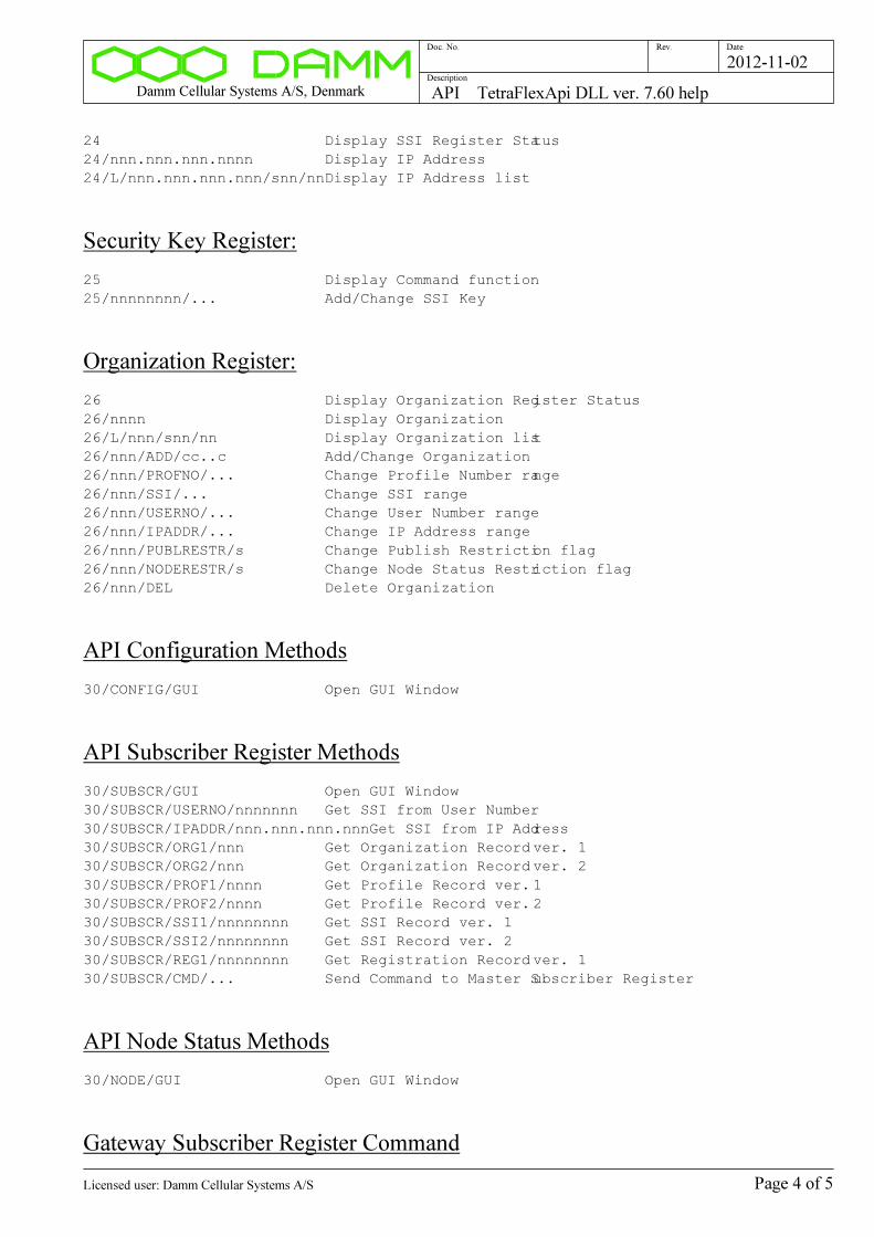
24 Display SSI Register Status
24/nnn.nnn.nnn.nnnn Display IP Address
24/L/nnn.nnn.nnn.nnn/snn/nnDisplay IP Address list
Security Key Register:
25 Display Command function
25/nnnnnnnn/... Add/Change SSI Key
Organization Register:
26 Display Organization Register Status
26/nnnn Display Organization
26/L/nnn/snn/nn Display Organization list
26/nnn/ADD/cc..c Add/Change Organization
26/nnn/PROFNO/... Change Profile Number range
26/nnn/SSI/... Change SSI range
26/nnn/USERNO/... Change User Number range
26/nnn/IPADDR/... Change IP Address range
26/nnn/PUBLRESTR/s Change Publish Restriction flag
26/nnn/NODERESTR/s Change Node Status Restriction flag
26/nnn/DEL Delete Organization
API Configuration Methods
30/CONFIG/GUI Open GUI Window
API Subscriber Register Methods
30/SUBSCR/GUI Open GUI Window
30/SUBSCR/USERNO/nnnnnnn Get SSI from User Number
30/SUBSCR/IPADDR/nnn.nnn.nnn.nnnGet SSI from IP Address
30/SUBSCR/ORG1/nnn Get Organization Record ver. 1
30/SUBSCR/ORG2/nnn Get Organization Record ver. 2
30/SUBSCR/PROF1/nnnn Get Profile Record ver. 1
30/SUBSCR/PROF2/nnnn Get Profile Record ver. 2
30/SUBSCR/SSI1/nnnnnnnn Get SSI Record ver. 1
30/SUBSCR/SSI2/nnnnnnnn Get SSI Record ver. 2
30/SUBSCR/REG1/nnnnnnnn Get Registration Record ver. 1
30/SUBSCR/CMD/... Send Command to Master Subscriber Register
API Node Status Methods
30/NODE/GUI Open GUI Window
Gateway Subscriber Register Command
Page 4 of 5Licensed user: Damm Cellular Systems A/S

Damm Cellular Systems A/S, Denmark API TetraFlexApi DLL ver. 7.60 help
Doc. No. Rev. Date
Description
2012-11-02
51 Display Command function
51/D Display Last Command to Gateway
51/cc..c Send Subscriber Register Command to Gateway
CPU Performance:
66 Display CPU Performance
66/C Clear Peak Hold Times
66/T Display 1msec. timer
66/Q Display Query Performance Counter
API DLL Configuration Commands:
70 Display last file save result
70/SAVE Save DLL API Configuration
General API DLL configuration:
71 Display General API DLL configuration
71/IDPROMPT/+ Prompt User for ID
71/IDPROMPT/- Use ID in configuration
71/USERNO/nnnnnnn Select/change Own User Number ID
71/TSI/nnnn:nnnnn:nnnnnnnn Select/change Own Tetra Subscriber ID
71/PIN/+ Prompt User for Pin Code
71/PIN/- Disable use of Pin Code
71/PIN/nnnnnnnnn Setup/Change PIN Code
71/OMPORT/nnnnn Change OM TCP Port Number
71/OMPIN/nn..n Change OM PIN Code
Gateway configuration:
72 Display Gateways
72/n/nnn.nnn.nnn.nnn/... Add/Change Gateway
72/n/- Remove Gateway
Page 5 of 5Licensed user: Damm Cellular Systems A/S
Damm Cellular Systems A/S, Denmark TR412 Transceiver ver. 7.60 help
Doc. No. Rev. Date
Description
2012-11-02
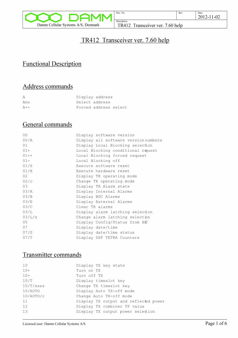
TR412 Transceiver ver. 7.60 help
Functional Description
Address commands
A Display address
Ann Select address
A++ Forced address select
General commands
00 Display software version
00/A Display all software version numbers
01 Display Local Blocking selection
01+ Local Blocking conditional request
01++ Local Blocking forced request
01- Local Blocking off
01/S Execute software reset
01/H Execute hardware reset
02 Display TR operating mode
02/c Change TR operating mode
03 Display TR Alarm state
03/A Display Internal Alarms
03/B Display BSC Alarms
03/E Display External Alarms
03/C Clear TR alarms
03/L Display alarm latching selection
03/L/s Change alarm latching selection
05 Display Config/Status from BSC
07 Display date/time
07/S Display date/time status
07/T Display DSP TETRA Counters
Transmitter commands
10 Display TX key state
10+ Turn on TX
10- Turn off TX
10/T Display timeslot key
10/T/ssss Change TX timeslot key
10/AUTO Display Auto TX-off mode
10/AUTO/c Change Auto TX-off mode
11 Display TX output and reflected power
12 Display TX combiner TP value
13 Display TX output power selection
Page 1 of 6Licensed user: Damm Cellular Systems A/S
Damm Cellular Systems A/S, Denmark TR412 Transceiver ver. 7.60 help
Doc. No. Rev. Date
Description
2012-11-02
13/+nn.n Change TX output power
13/MIN Change TX output power to minimum
13/MAX Change TX output power to maximum
13/RED/+nn.n Change Reduced TX output power
13/RED/MIN Change Reduced TX output power to minimum
13/RED/MAX Change Reduced TX output power to maximum
15 Display TX test modulation selection
15/ZERO Select zero modulation
15/CW Select CW modulation
15/CW/PEP Select CW modulation PEP value
15/CW/IQ Display I/Q values for CW modulation
15/CW/cs Select CW modulation
15/CW/IQ/snnnnn/snnnnnSelect CW modulation with I/Q values
15/DSB/c/n Select DSB modulation
15/cSB/n Select SSB modulation
15/PRBS9 Select TETRA PRBS-9 modulation
15/PRBS15 Select TETRA PRBS-15 modulation
15/PH45 Select TETRA +/-45deg. modulation
15/FM/3 Select FM 1kHz +/-3kHz
15/MULTI Select DSB multitone modulation
16 Display TX filter type
16/n Change TX filter type
17 Display TX status
17/IQ Display TX IQ values
18 Display cartesian loop selection
18- Select open cartesian loop
18+ Select closed cartesian loop
18/P TX cartesian loop phase measurement
18/A TX cartesian loop phase/ampl. measurement
18/FREQ TX cartesian loop phase vs frequency measurement
18/PWR TX cartesian loop phase vs. power measurement
18/ADJUST TX cartesian open loop phase adjust
19 Display command function
19/F Select fast TX PLL loop
19/S Select slow TX PLL loop
19/FREQ Display TX PLL voltage vs frequency
19+ Switch TX on and off continuously
19/nnnn Switch TX channel continuously between current and nnnn
Receiver commands
20 Display RX LO status
21 Display RX RSSI
21/c Display RX RSSI
21/NF Display RX Noise Figure
21/FFT/c Display FFT result
21/FFT/c/2 Display 2.25kHz FFT amplitude results
22 Display RX diversity selection
22/A A-forced RX diversity selection
22/B B-forced RX diversity selection
22- Automatic RX diversity selection
23 Display command function
23+ RX antenna measurement command
Page 2 of 6Licensed user: Damm Cellular Systems A/S
Damm Cellular Systems A/S, Denmark TR412 Transceiver ver. 7.60 help
Doc. No. Rev. Date
Description
2012-11-02
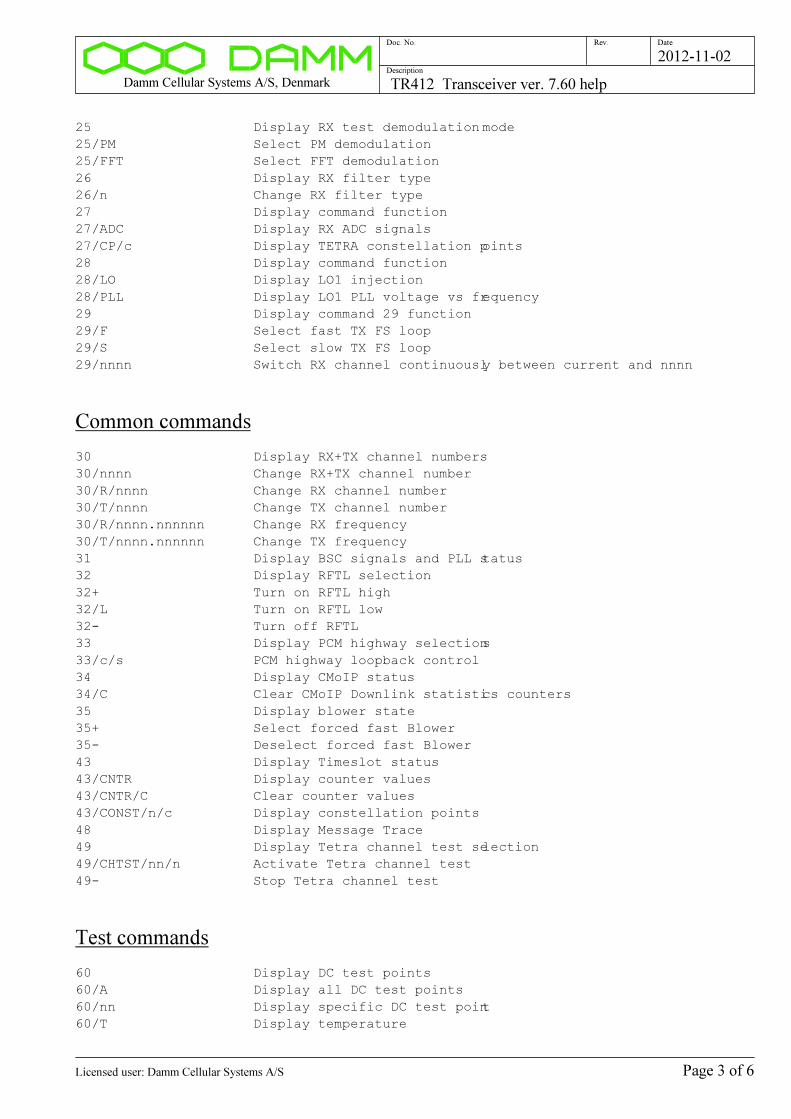
25 Display RX test demodulation mode
25/PM Select PM demodulation
25/FFT Select FFT demodulation
26 Display RX filter type
26/n Change RX filter type
27 Display command function
27/ADC Display RX ADC signals
27/CP/c Display TETRA constellation points
28 Display command function
28/LO Display LO1 injection
28/PLL Display LO1 PLL voltage vs frequency
29 Display command 29 function
29/F Select fast TX FS loop
29/S Select slow TX FS loop
29/nnnn Switch RX channel continuously between current and nnnn
Common commands
30 Display RX+TX channel numbers
30/nnnn Change RX+TX channel number
30/R/nnnn Change RX channel number
30/T/nnnn Change TX channel number
30/R/nnnn.nnnnnn Change RX frequency
30/T/nnnn.nnnnnn Change TX frequency
31 Display BSC signals and PLL status
32 Display RFTL selection
32+ Turn on RFTL high
32/L Turn on RFTL low
32- Turn off RFTL
33 Display PCM highway selections
33/c/s PCM highway loopback control
34 Display CMoIP status
34/C Clear CMoIP Downlink statistics counters
35 Display blower state
35+ Select forced fast Blower
35- Deselect forced fast Blower
43 Display Timeslot status
43/CNTR Display counter values
43/CNTR/C Clear counter values
43/CONST/n/c Display constellation points
48 Display Message Trace
49 Display Tetra channel test selection
49/CHTST/nn/n Activate Tetra channel test
49- Stop Tetra channel test
Test commands
60 Display DC test points
60/A Display all DC test points
60/nn Display specific DC test point
60/T Display temperature
Page 3 of 6Licensed user: Damm Cellular Systems A/S
Damm Cellular Systems A/S, Denmark TR412 Transceiver ver. 7.60 help
Doc. No. Rev. Date
Description
2012-11-02
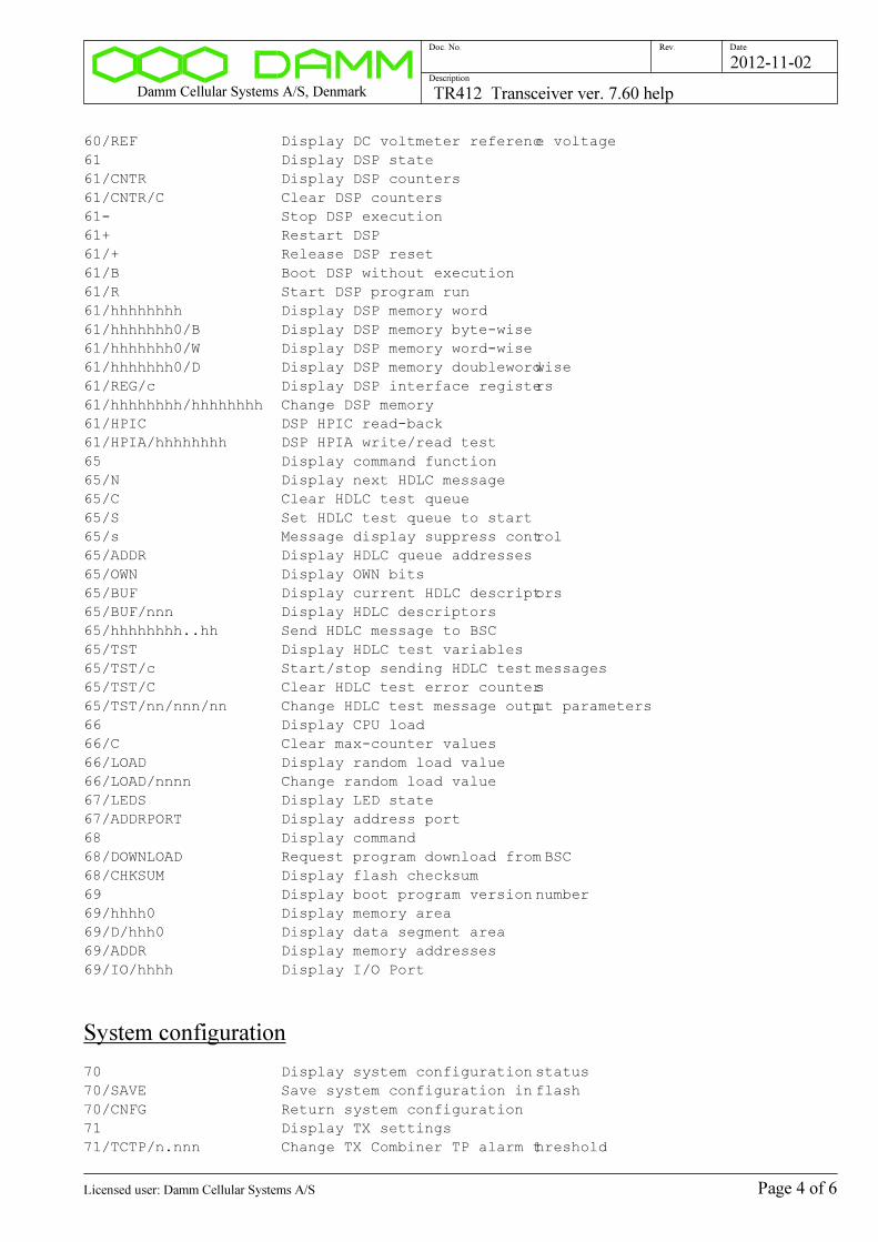
60/REF Display DC voltmeter reference voltage
61 Display DSP state
61/CNTR Display DSP counters
61/CNTR/C Clear DSP counters
61- Stop DSP execution
61+ Restart DSP
61/+ Release DSP reset
61/B Boot DSP without execution
61/R Start DSP program run
61/hhhhhhhh Display DSP memory word
61/hhhhhhh0/B Display DSP memory byte-wise
61/hhhhhhh0/W Display DSP memory word-wise
61/hhhhhhh0/D Display DSP memory doublewordwise
61/REG/c Display DSP interface registers
61/hhhhhhhh/hhhhhhhh Change DSP memory
61/HPIC DSP HPIC read-back
61/HPIA/hhhhhhhh DSP HPIA write/read test
65 Display command function
65/N Display next HDLC message
65/C Clear HDLC test queue
65/S Set HDLC test queue to start
65/s Message display suppress control
65/ADDR Display HDLC queue addresses
65/OWN Display OWN bits
65/BUF Display current HDLC descriptors
65/BUF/nnn Display HDLC descriptors
65/hhhhhhhh..hh Send HDLC message to BSC
65/TST Display HDLC test variables
65/TST/c Start/stop sending HDLC test messages
65/TST/C Clear HDLC test error counters
65/TST/nn/nnn/nn Change HDLC test message output parameters
66 Display CPU load
66/C Clear max-counter values
66/LOAD Display random load value
66/LOAD/nnnn Change random load value
67/LEDS Display LED state
67/ADDRPORT Display address port
68 Display command
68/DOWNLOAD Request program download from BSC
68/CHKSUM Display flash checksum
69 Display boot program version number
69/hhhh0 Display memory area
69/D/hhh0 Display data segment area
69/ADDR Display memory addresses
69/IO/hhhh Display I/O Port
System configuration
70 Display system configuration status
70/SAVE Save system configuration in flash
70/CNFG Return system configuration
71 Display TX settings
71/TCTP/n.nnn Change TX Combiner TP alarm threshold
Page 4 of 6Licensed user: Damm Cellular Systems A/S
Damm Cellular Systems A/S, Denmark TR412 Transceiver ver. 7.60 help
Doc. No. Rev. Date
Description
2012-11-02
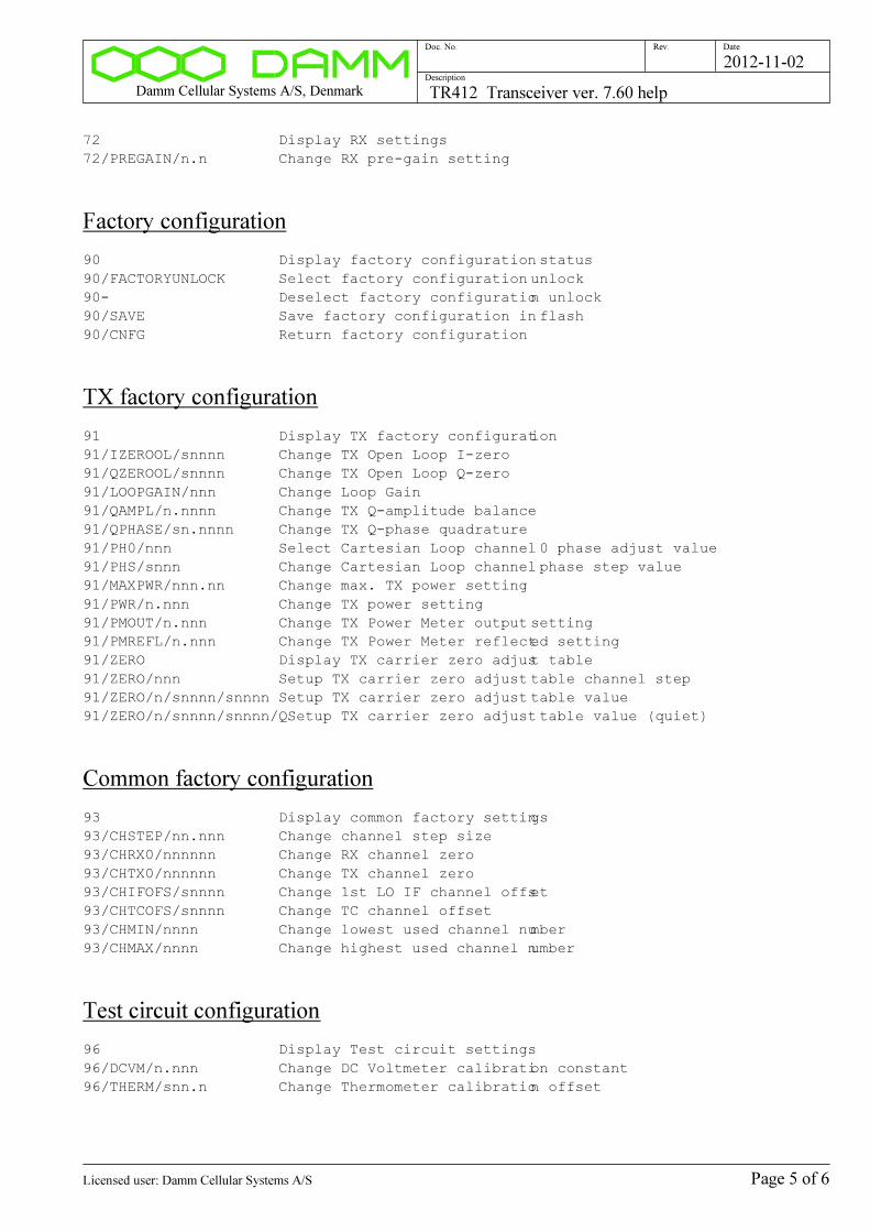
72 Display RX settings
72/PREGAIN/n.n Change RX pre-gain setting
Factory configuration
90 Display factory configuration status
90/FACTORYUNLOCK Select factory configuration unlock
90- Deselect factory configuration unlock
90/SAVE Save factory configuration in flash
90/CNFG Return factory configuration
TX factory configuration
91 Display TX factory configuration
91/IZEROOL/snnnn Change TX Open Loop I-zero
91/QZEROOL/snnnn Change TX Open Loop Q-zero
91/LOOPGAIN/nnn Change Loop Gain
91/QAMPL/n.nnnn Change TX Q-amplitude balance
91/QPHASE/sn.nnnn Change TX Q-phase quadrature
91/PH0/nnn Select Cartesian Loop channel 0 phase adjust value
91/PHS/snnn Change Cartesian Loop channel phase step value
91/MAXPWR/nnn.nn Change max. TX power setting
91/PWR/n.nnn Change TX power setting
91/PMOUT/n.nnn Change TX Power Meter output setting
91/PMREFL/n.nnn Change TX Power Meter reflected setting
91/ZERO Display TX carrier zero adjust table
91/ZERO/nnn Setup TX carrier zero adjust table channel step
91/ZERO/n/snnnn/snnnn Setup TX carrier zero adjust table value
91/ZERO/n/snnnn/snnnn/QSetup TX carrier zero adjust table value (quiet)
Common factory configuration
93 Display common factory settings
93/CHSTEP/nn.nnn Change channel step size
93/CHRX0/nnnnnn Change RX channel zero
93/CHTX0/nnnnnn Change TX channel zero
93/CHIFOFS/snnnn Change 1st LO IF channel offset
93/CHTCOFS/snnnn Change TC channel offset
93/CHMIN/nnnn Change lowest used channel number
93/CHMAX/nnnn Change highest used channel number
Test circuit configuration
96 Display Test circuit settings
96/DCVM/n.nnn Change DC Voltmeter calibration constant
96/THERM/snn.n Change Thermometer calibration offset
Page 5 of 6Licensed user: Damm Cellular Systems A/S

Damm Cellular Systems A/S, Denmark TR412 Transceiver ver. 7.60 help
Doc. No. Rev. Date
Description
2012-11-02
Hardware identity
98 Display hardware ID
98/TYPE Display type number
98/ITEM Display item number
98/SER Display serial number
98/VER Display version number
98/REV Display revision number
98/ITEM/cc..c Change item number
98/SER/cc..c Change serial number
98/VER/n.nn Change version number
98/REV/n Change revision number
Page 6 of 6Licensed user: Damm Cellular Systems A/S
Damm Cellular Systems A/S, Denmark TR421 Transceiver ver. 7.60 help
Doc. No. Rev. Date
Description
2012-11-02
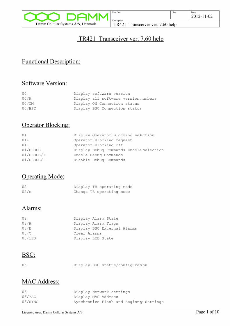
TR421 Transceiver ver. 7.60 help
Functional Description:
Software Version:
00 Display software version
00/A Display all software version numbers
00/OM Display OM Connection status
00/BSC Display BSC Connection status
Operator Blocking:
01 Display Operator Blocking selection
01+ Operator Blocking request
01- Operator Blocking off
01/DEBUG Display Debug Commands Enable selection
01/DEBUG/+ Enable Debug Commands
01/DEBUG/- Disable Debug Commands
Operating Mode:
02 Display TR operating mode
02/c Change TR operating mode
Alarms:
03 Display Alarm State
03/A Display Alarm Flags
03/E Display BSC External Alarms
03/C Clear Alarms
03/LED Display LED State
BSC:
05 Display BSC status/configuration
MAC Address:
06 Display Network settings
06/MAC Display MAC Address
06/SYNC Synchronize Flash and Registry Settings
Page 1 of 10Licensed user: Damm Cellular Systems A/S
Damm Cellular Systems A/S, Denmark TR421 Transceiver ver. 7.60 help
Doc. No. Rev. Date
Description
2012-11-02
06/NAME/cc.c Setup Host Name
06/DHCP/s Setup DHCP
06/IPADDR/... Setup IP Address
06/IPMASK/... Setup IP Mask
06/IPGW/... Setup IP Default Gateway
06/MAC/hh-hh-hh Setup MAC Address
06/10MBIT/s Change 10MBit/s Forced Flag
Date/Time:
07 Display Current Local Date/Time
07/S Display Date/Time status
07/T Display DSP TETRA Counters
TX Key:
10 Display TX key state
10+ Turn on TX
10- Turn off TX
10/T Display timeslot key
10/T/ssss Change TX timeslot key
10/AUTO Display Auto TX-off mode
10/AUTO/c Change Auto TX-off mode
TX Output Power:
11 Display TX output and reflected power
TX Current/Power consumption:
12 Display TX Current/Power consumption
12/P Display PA Power
TX Output Power selection:
13 Display TX output power selection
13/+nn.n Change TX Normal Output Power setting
13/MIN Set TX Normal Output Power to Minimum
13/MAX Set TX Normal Output Power to Maximum
13/RED/+nn.n Change Reduced TX Output Power setting
13/RED/MIN Set TX Reduced Output Power to Minimum
13/RED/MAX Set TX Reduced Output Power to Maximum
TX PA DC Bias:
14 Display TX Bias
Page 2 of 10Licensed user: Damm Cellular Systems A/S
Damm Cellular Systems A/S, Denmark TR421 Transceiver ver. 7.60 help
Doc. No. Rev. Date
Description
2012-11-02
14+ Select TX Bias Forced On
14- Select TX Bias Off (DSP Controlled)
TX modulation:
15 Display TX test modulation selection
15/ZERO Select zero modulation
15/CW Select CW modulation
15/CW/PEP Select CW modulation PEP value
15/CW/cs Select CW modulation
15/CW/IQ/snnnnn/snnnnnSelect CW modulation with I/Q values
15/PRBS9 Select TETRA PRBS-9 modulation
15/PRBS15 Select TETRA PRBS-15 modulation
15/DSB/c/n Select DSB modulation
15/cSB/n Select SSB modulation
15/FM/3 Select FM 1kHz +/-3kHz
15/MULTI Select DSB multitone modulation
15/PH45 Select TETRA +/-45deg. modulation
TX modulation filter:
16 Display TX filter type
16/n Change TX filter type
TX status:
17 Display TX status
TX Cartesial Loop:
18 Display TX cartesian loop selections
18- Select open cartesian loop
18+ Select closed cartesian loop
18/P TX cartesian loop phase measurement
18/A TX cartesian loop phase/ampl. measurement
18/FREQ TX cartesian loop phase vs frequency measurement
18/PWR TX cartesian loop phase vs. power measurement
18/LIN TX linearity measurement
18/ADJ TX cartesian open loop phase adjust
TX utility commands:
19 Display command function
19/F Display TX PLL voltage vs frequency
19+ Switch TX on and off
19/nnnn Switch TX channel to nnnn and back again
Page 3 of 10Licensed user: Damm Cellular Systems A/S

Damm Cellular Systems A/S, Denmark TR421 Transceiver ver. 7.60 help
Doc. No. Rev. Date
Description
2012-11-02
RX Local Oscillators:
20 Display RX LO status
RX RSSI:
21 Display RX RSSI
21/c Display RX RSSI
21/NF Display RX Noise Figure
21/FFT Display FFT result
21/FFT/A Display FFT Adjust results
21/FREQ Display RX Signal Frequency Offset
RX Diversity:
22 Display RX diversity selection
22/A A-forced RX diversity selection
22/B B-forced RX diversity selection
22- Automatic RX diversity selection
RX Antenna test:
23 Display command function
23+ RX antenna measurement command
RX-B Input:
24 Display RX-B Input Selection
24+ Select RX-B input Cascaded
24- Deselect RX-B input Cascaded
RX demodulation mode:
25 Display RX test demodulation mode
25/PM Select PM demodulation
25/FFT/A Select RX-A FFT demodulation
25/FFT/B Select RX-B FFT demodulation
25/FREQ/A Select RX-A Frequency Measurement
25/FREQ/B Select RX-B Frequency Measurement
RX IF filter:
26 Display RX filter selection
Page 4 of 10Licensed user: Damm Cellular Systems A/S

Damm Cellular Systems A/S, Denmark TR421 Transceiver ver. 7.60 help
Doc. No. Rev. Date
Description
2012-11-02
26/n Change RX filter type
RX Signal Display:
27 Display command function
27/CP/c Display TETRA Constellation Points
27/ADC Display ADC peak-peak input levels
RX adjust commands:
28 Display command function
28/LO Display LO1 injection
28/BPF Display RSSI vs. Frequency
RX utility commands:
29 Display command function
29/F Display RX PLL voltage vs frequency
29/nnnn Switch RX to channel nnnn and back again
Channel/Frequency:
30 Display RX+TX channel numbers and frequencies
30/F Display Hardware Frequency Range
30/nnnn Change RX+TX channel number
30/R/nnnn Change RX channel number
30/T/nnnn Change TX channel number
30/R/nnn.nnnnnn Change RX frequency
30/T/nnn.nnnnnn Change TX frequency
Synchronization
31 Display Sync status
31/IN Display Sync Input status
31/IN/c Change Sync Input selection
31/SET Set OCXO Free Run adjust value to current DAC value
31/SET/nn.nnn Set OCXO Free Run value
31/SAVE Save OCXO Free Run adjust value in Flash
31/PPS Display 1 PPS inputs
31/HIST Display OCXO Sync history
31/STEP/nn.nnn Simulate a PLL Frequency Step
RFTL:
32 Display RFTL selection
32+ Turn on RFTL Forward
Page 5 of 10Licensed user: Damm Cellular Systems A/S

Damm Cellular Systems A/S, Denmark TR421 Transceiver ver. 7.60 help
Doc. No. Rev. Date
Description
2012-11-02
32/B Turn on RFTL Backward
32- Turn off RFTL
32/nnn Select RFTL Forward Level
32/ATT Display RFTL Attenuator value
Duplex Filter:
33 Display Duplex Filter Selection
33+ Select Duplex Filter
33- Deselect Duplex Filter
CMoIP:
34 Display all CMoIP Connections
34/n Display one CMoIP Connection
34/n/... CMoIP Multicast Connect
34/n/REL CMoIP Multicast Release
34/C Clear CMoIP Downlink Statistics Couters
34/Q Display CMoIP DSP queues
MAC
43 Display Command Function
43/CONST/n/c Display Constellation Points
43/LMAC Display LMAC Message Statistics
43/LMAC/C Clear LMAC Message Counter
BSC Message Count:
47 Display BSC message count
47/C Clear BSC message count
Message Trace:
48 Display message trace
48+ Start Trace of all TS to UDP
48- Stop Trace of all TS to UDP
48/UDP/+ Activate trace output to UDP
48/UDP/- Stop trace output to UDP
48/UDP/nnn... Change trace UDP address+port
48/FILE/+ Open trace output file
48/FILE/- Close trace output file
48/FILE/cc..c Change trace filename
48/n/c Start/Stop Timeslot Trace
48/C Clear Trace Counters
Page 6 of 10Licensed user: Damm Cellular Systems A/S

Damm Cellular Systems A/S, Denmark TR421 Transceiver ver. 7.60 help
Doc. No. Rev. Date
Description
2012-11-02
Tetra Channel Test:
49 Display Tetra channel test selection
49/nn/n Activate Tetra channel test
49- Stop Tetra channel test
49/c Change Sync Mode
49/CNTR Display Counters
49/CLEAR Clear Counter Values
49/DATA Display Received Data
DC Voltmeter:
60 Display DC test points
60/nn Display one DC test point
60/T Display temperature
60/ADC Display voltmeter ADC values
DSP:
61 Display DSP state
61- Stop DSP execution
61+ Restart DSP
61/B Select DSP Boot State
61/S Select DSP Setup State
61/R Start DSP program run
61/hhhhhhhh Display DSP memory word
61/hhhhhhh0/1 Display DSP memory 8-bit wise
61/hhhhhhh0/2 Display DSP memory 16-bit wise
61/hhhhhhh0/4 Display DSP memory 32-bit wise
61/hhhhhhhh/hhhhhhhh Change DSP memory
61/REG/nn Display DSP interface registers
61/REG/nn/nn Display DSP interface registers
61/HPIA/hhhhhhhh DSP HPIA write/read test
61/HPIC Display HPI Control Register
CPLD:
62 Display CPLD version
Internal GPS:
63 Display Internal GPS Status
63/VER Display GPS Module Version
63/N Display next Internal GPS message
63/SETUP Setup GPS RX Module
Page 7 of 10Licensed user: Damm Cellular Systems A/S

Damm Cellular Systems A/S, Denmark TR421 Transceiver ver. 7.60 help
Doc. No. Rev. Date
Description
2012-11-02
63/SEND/cc..c Send Command to GPS RX Module
63/RESET/s GPS RX Module Reset
Message Test Queue:
65 Display BSC Link Connection status
65/N Display next message
65/C Clear test queue
65/S Set test queue to start
65/s Message display suppress control
65/c/hh/hh..hh Send message
Host Performance:
66 Display Host CPU task load
66/C Clear Host CPU Load Peak Hold
66/T Display 1msec. Timer
66/Q Display QPC Counter
Real Time Clock:
68 Display RTC NVRAM
68/hh/hh Change RTC NVRAM
Host Memory:
69 Display command function
69/hhhhhhhh Display Host memory word
69/hhhhhhh0/1 Display Host memory 8-bit wise
69/hhhhhhh0/2 Display Host memory 16-bit wise
69/hhhhhhh0/4 Display Host memory 32-bit wise
69/hhhhhhhh/hhhhhhhh Change Host memory
System configuration:
70 Display command function
70/SAVE Save System Configuration
Common system configuration:
71 Display Common System configuration
71/ID/cc..c Change TR ID String
71/TRADDR/nn Change TR Address
71/MSGPORT/nnnnn Change Local Message Port Number
71/BSC/n/s Change BSC Configuration
71/BSC/n/nnn.nnn.nnn.nnnChange BSC IP Address
Page 8 of 10Licensed user: Damm Cellular Systems A/S
Damm Cellular Systems A/S, Denmark TR421 Transceiver ver. 7.60 help
Doc. No. Rev. Date
Description
2012-11-02
71/BSC/n/s Change BSC Connection Protocol
71/BSC/n/nnnnn Change BSC Remote Port Number
71/CMOIP/BSS/s Change CMoIP to BSS selection
71/CMOIP/BSS/n/nnn.nnn.nnn.nnnChange CMoIP BSS IP Address
71/TXREFLWAR/c Change TX Reflected Alarm selection
Synchronization configurations
72 Display Sync selection
72/MASTER/c Change Master Priority
72/CENTSECOFS/snnnnnnnnnnChange Century Second offset
72/CENTSECOFS/DAMM Change Century Second offset to DAMM
72/CENTSECOFS/EADS Change Century Second offset to EADS
72/GPSRXOFS/snnn.n Change GPS RX offset
72/GPSRXOFS/DAMM Change GPS RX offset to DAMM
72/GPSRXOFS/EADS Change GPS RX offset to EADS
72/IN/n/s Activate/Deactivate Sync Input
72/IN/n/... Setup External Sync Input
72/OUT Display Sync Message Output Table
72/OUT/... Add/Remove Sync Message Output
Factory configuration:
90 Display factory lock status
90/FACTORYUNLOCK Select factory configuration unlock
90- Deselect factory configuration unlock
90/CNFG Return current Factory Configuration
90/FLASH Return Factory Configuration in Flash
90/SAVE Save Factory Configuration in Flash
90/CLEAR Clear Flash Factory Configuration
TX factory configuration:
91 Display TX factory configuration
91/PWRADJ/n.nnn Change TX Output Power
91/BIASDR/nnn Change TX Driver Bias
91/BIASPA/nnn Change TX PA Bias
91/IZEROOL/snnnn Change TX Open Loop I-zero
91/QZEROOL/snnnn Change TX Open Loop Q-zero
91/LOOPGAIN/nnn Change Loop Gain
91/QAMPL/n.nnnn Change TX Q-amplitude balance
91/QPHASE/sn.nnnn Change TX Q-phase quadrature
91/PH0/nnn Select Cartesian Loop channel 0 phase adjust value
91/PHSTEP/snnn Change Cartesian Loop channel phase step value
91/ZERO Display TX carrier zero adjust table
91/ZERO/nnn Setup TX carrier zero adjust table channel step
91/ZERO/n/snnnn/snnnn Setup TX carrier zero adjust table value
91/PMOUT/n.nnn Change TX Power Meter output setting
91/PMREFL/n.nnn Change TX Power Meter reflected setting
Page 9 of 10Licensed user: Damm Cellular Systems A/S

Damm Cellular Systems A/S, Denmark TR421 Transceiver ver. 7.60 help
Doc. No. Rev. Date
Description
2012-11-02
Common factory configuration:
93 Display common factory settings
93/CHIFOFS/snnnn Change 1st LO IF channel offset
93/CHRX0/nnnnnn Change RX channel zero
93/CHTX0/nnnnnn Change TX channel zero
93/CHTRMIN/nnnn Change lowest Transceiver channel number
93/CHTRMAX/nnnn Change highest Transceiver channel number
93/CHDFMIN/nnnn Change lowest Duplex Filter channel number
93/CHDFMAX/nnnn Change highest Duplex Filter channel number
93/DFTXLOSS/n.n Duplex Filter TX Path Loss
93/DFRXALOSS/n.n Duplex Filter RX-A Path Loss
93/DFRXBLOSS/n.n Duplex Filter RX-B Path Loss
93/SYNCEXT2/c Sync External 2 input selection
93/GPSRX/c GPS RX Type selection
Hardware identity:
98 Display Hardware Identity
98/ITEM/cc..c Change item number
98/SER/cc..c Change serial number
98/VER/cc..c Change version number
98/REV/cc..c Change revisions
98/DFSER/cc..c Change Duplex Filter Serial No.
TR421 Control Commands
99 Display command function
99/STOP Stop TR421 service
99/RESTART Restart TR421 service
99/HWRESET Make BS421 Hardware Reset
Page 10 of 10Licensed user: Damm Cellular Systems A/S

Damm Cellular Systems A/S, Denmark PS411 Power Supply ver. 1.00 help
Doc. No. Rev. Date
Description
2011-08-18
PS411 Power Supply ver. 1.00 help
Functional Description
Address commands
A Display address
Anc Select address
A++ Forced address select
General commands
00 Display software version number
02 Display command function
02+ Execute software reset
02++ Execute hardware reset
03 Display alarm status
03/C Alarm reset
Output commands
10 Display output values
11 Display 14V output selection
11- Turn off 14V output
11+ Turn on 14V output
12 Display 26V output selection
12- Turn off 26V output
12+ Turn on 26V output
Rectifier commands
20 Display Rectifier status
21 Display Rectifier selection
21- Turn off Rectifier
21+ Turn on Rectifier
22 Display Rectifier manual voltage control selection
22+ Select Rectifer manual voltage control
22- Deselect Rectifier manual voltage control
23 Display Rectifier output voltage selection
23/nn.n Change Rectifier output voltage
Battery charging commands
Page 1 of 2Licensed user: Damm Cellular Systems A/S

Damm Cellular Systems A/S, Denmark PS411 Power Supply ver. 1.00 help
Doc. No. Rev. Date
Description
2011-08-18
30 Display battery status
Test commands
60 Display temperature
63 Display timer
65 Display command function
65/N Display next message
65/C Clear test queue
65/hhhh..hh Send message to BSC
65/L Enable loop-back reception
67 Display Board Address
69 Display last selected memory address
69/hhhh Display memory address hhhh
System settings
70 Display system settings
71 Display AC input selection
71s Change AC input selection
71/EE++++ Save AC input selection in EEPROM
72 Display Battery charging selection
72s Change Battery charging selection
72/EE++++ Save Battery charging selection in EEPROM
73 Display Battery charging voltage selection
73/nn.n Select Battery charging voltage
73/EE++++ Save Battery charging voltage in EEPROM
74 Display Battery charging temperature compensation
74/-nnn Select Battery charging temperature compensation
74/EE++++ Save Battery charging temperature compensation in EEPROM
Factory settings
90 Display factory unlock selection
90/UNLOCK Select factory unlock
90- Deselect factory unlock
91 Display PS Rectifier selection
91+ Select Rectifier included
91- Select No Rectifier included
95 Display Item number
95/ccc..c Change Item number
96 Display Type number
96/ccc..c Change Type number
97 Display Serial number
97/nnnnnnnn Change serial number
98 Display Version number
98/cc..c Change Version number
99 Display Revision number
99/cc..c Change Revision number
Page 2 of 2Licensed user: Damm Cellular Systems A/S
Damm Cellular Systems A/S, Denmark PS421 Power Supply ver. 1.00 help
Doc. No. Rev. Date
Description
2007-03-10
PS421 Power Supply ver. 1.00 help
Functional Description
General commands
00 Display software version number
02 Display command function
02+ Execute hardware reset
03 Display alarm flags
PS commands
10 Display PS Status
11 Display TR1/TR3 Power-Off Selection
11+ Turn On TR1/TR3 Power
11- Turn Off TR1/TR3 Power
12 Display TR2/TR4 Power-Off Selection
12+ Turn On TR2/TR4 Power
12- Turn Off TR2/TR4 Power
Rectifier commands
20 Display Rectifier status
21 Display Rectifier Off selection
21- Turn Off Rectifier
21+ Turn On Rectifier
22 Display Rectifier Manual Voltage Control selection
22+ Select Rectifer Manual Voltage Control
22- Deselect Rectifier Manual Voltage Control
23 Display Rectifier Output Voltage selection
23/nn.n Change Rectifier Output Voltage
24 Display Battery Super Charge Status
24/n.n/nnn Start Battery Super Charge
24- Stop Battery Super Charge
Test commands
60 Display ADC Result
67 Display Input Port
68 Display command function
68/BOOT Switch to Boot Mode
69 Display last selected memory address
69/hhhh Display memory address hhhh
Page 1 of 2Licensed user: Damm Cellular Systems A/S
Damm Cellular Systems A/S, Denmark PS421 Power Supply ver. 1.00 help
Doc. No. Rev. Date
Description
2007-03-10
System Configuration
70 Display System Configuration
70/SAVE Save System Configuration in Flash
71 Display AC input selection
71s Change AC input selection
72 Display Battery charging selection
72s Change Battery charging selection
73 Display Battery charging voltage selection
73/nn.n Select Battery charging voltage
74 Display Battery charging temperature compensation
74/-nnn Select Battery charging temperature compensation
Factory Configuration
90 Display Factory Configuration
90/D Display factory unlock selection
90/UNLOCK Select factory unlock
90- Deselect factory unlock
90/SAVE Save Factory Configuration in Flash
91 Display Rectifier selection
91+ Select Rectifier included
91- Select No Rectifier included
95 Display Item Number
95/ccc..c Change Item Number
96 Display Type Number
96/ccc..c Change Type Number
97 Display Serial Number
97/nnnnnnnn Change Serial Number
98 Display Version Number
98/cc..c Change Version Number
99 Display Revision Number
99/cc..c Change Revision Number
Page 2 of 2Licensed user: Damm Cellular Systems A/S
Damm Cellular Systems A/S, Denmark TCC411 TX Combiner Controller ver. 2.00 help
Doc. No. Rev. Date
Description
2007-03-10
TCC411 TX Combiner Controller ver. 2.00 help
Functional Description
Address commands
A Display address
Anc Select address
General commands
00 Display software version number
01 Display blocking state
01+ Make blocking
01- Make deblocking
02 Display command function
02+ Execute software reset
02++ Execute hardware reset
Combiner control commands
10 Display frequencies
10/n Display frequency
10/n/+ Step up one channel
10/n/- Step down one channel
10/n/nnnn Change channel no.
10/n/E Go to end stop
10/n/EE++++ Save channel no. in EEPROM
11 Display operating mode
11- Select manual operating mode
11+ Select automatic operating mode
11/EE++++ Save operating mode in EEPROM
12 Display all test points
12/n Display test point
13 Display fine adjustment settings
13/n Display fine adjustment setting
13/n/+ Increment fine adjustment setting
13/n/- Decrement fine adjustment setting
13/n/snn Change fine adjustment setting
13/n/EE++++ Save fine adjustment setting in EEPROM
Motor control commands
20 Display motor positions
20/n Display motor position
Page 1 of 2Licensed user: Damm Cellular Systems A/S
Damm Cellular Systems A/S, Denmark TCC411 TX Combiner Controller ver. 2.00 help
Doc. No. Rev. Date
Description
2007-03-10
20/n/+ Step up motor position
20/n/- Step down motor position
20/n/nnnn Change motor position
20/n/++ Forced step up motor position
20/n/E Init to end stop
21 Display command function
21/n/C Motor continuous up/down
Test commands
60 Display temperature
67 Display TR serial input port levels
68 Display input port
69 Display last selected memory address
69/hhhh Display memory address hhhh
Calibration
80 Display calibration unlock selection
80/UNLOCK Unlock for calibration
81 Display start frequency
81/nnnn Change start frequency
82 Display channel separation
82/nn Change channel separation
83 Display calibration channel spacing
83/nn Change calibration channel spacing
84 Display end stop position
84/nnnn Change end stop position
85 Display command function
85/n Display calibration values
85/n/nn Display calibration value
85/n/nn/SET Set calibration point to current position
85/n/nn/nnnn Change calibration point value
Factory settings
90 Display BS type selection
90/c Change BS type selection
91 Display Thermometer setting
91/snn Change Thermometer setting
95 Display Item number
95/ccc..c Change Item number
96 Display Type number
96/ccc..c Change Type number
97 Display Serial number
97/nnnnnn Change 6-digit serial number
97/nnnnnnnn Change 8-digit serial number
98 Display Version number
98/cc..c Change Version number
99 Display Revision number
Page 2 of 2Licensed user: Damm Cellular Systems A/S
Damm Cellular Systems A/S, Denmark TCC411 TX Combiner Controller ver. 2.00 help
Doc. No. Rev. Date
Description
2007-03-10
99/cc..c Change Revision number
Page 3 of 2Licensed user: Damm Cellular Systems A/S
Damm Cellular Systems A/S, Denmark OM program help
Doc. No. Rev. Date
Description
2001-08-20
OM program help
OM
TetraOM command line parameters
Commands
C/... Continuous command
R/... Repeat command
!WAIT(hh:mm) Wait until a specific time
!DELAY(delay) Insert a delay, in steps of 1/10 of a second
!KEY Wait for keypress.
!ECHO(comments) Comments to be displayed with highlighted
text.
Logging
!LOG Show logging settings
!LOG(c,r,a,filename) Open or create logfile.
!LOG(CREATE,filename) Create and open logfile. Empty if already
exists.
!LOG(OPEN,filename) Open logfile. Append if exists.
!LOG(CLOSE) Close logfile
!LOG(SET,t,t,s,s,d,d) Enable/disable command/response logging
Options
!OPT Show options settings
!OPT(TIMEOUT,seconds) Set timeout in seconds
!OPT(LINEDELAY,ms) Set linedelay in milliseconds
!OPT(ECHO,s,s,d,d) Enable/disable echoing in terminal
!OPT(TERMWIN,xxx,yyy) Set terminal window size
!OPT(TERMFONTSIZE,s) Set terminal font size
Connections
!CONN Show number of items in connection list
!CONN(D,co,ba,a,n) Direct
!CONN(M,co,ba,a,n) Direct modem
!CONN(U,co,ba,ph,da,dti,rw,ati,a,n)Dialup modem
!CONN(N,ip,a,n) Network
Page 1 of 2Licensed user: Damm Cellular Systems A/S
Damm Cellular Systems A/S, Denmark OM program help
Doc. No. Rev. Date
Description
2001-08-20
Connect
!CONNECT(xxx.xxx.xxx.xxx) Connects to a new BSC
Disconnect
!DISCONNECT Disconnects from the current BSC
Fileview settings
!FILEVIEW Show number of items in the file view list
!FILEVIEW(name,teof,file) Insert item in file view list
Editor commands
SET command
:SET(var,value) Set variable value
For - Next Loops
:FOR(var,start,end) Define the start of a FOR/NEXT loop.
:FOR(var,start,end,stepsize) Define the start of a FOR/NEXT loop.
:NEXT(var) Repeat or end last defined FOR loop
Labels, jumps, conditional jumps.
:LABEL(labelname) Set destination of jumps.
:GOTO(labelname) Continue processing at a label.
:IFNORESP(nextlabel) Jump, if no response on communication-port.
:IFTIMEOUT(nextlabel) Jump, if general fault, on communication-port.
:IFINVALID(nextlabel) Jump, if reponse contained 'INVALID'
:IFEOD(nextlabel) Jump, if end of data-marker was read.
Special commands
:TIMEOUT(time) Setup timeout time on RS232 port
:EXECUTE(filename) Send file to port.
:INCLUDE(filename) Include file into command-list.
:SEND(....) Send command containing variables.
<cmd> Send command
Page 2 of 2Licensed user: Damm Cellular Systems A/S
Damm Cellular Systems A/S, Denmark MAIN BSC Main ver. 7.60 help
Doc. No. Rev. Date
Description
2012-11-02
MAIN BSC Main ver. 7.60 help
Functional Description
Page 1 of 21Licensed user: Damm Cellular Systems A/S
Damm Cellular Systems A/S, Denmark MAIN BSC Main ver. 7.60 help
Doc. No. Rev. Date
Description
2012-11-02
Address selection
A ADDRESS SELECTION
A Display Address selection
Displays selected address for nn commands
A
AP Select PS421 Address
Deselected again by selecting any other nn command address
NB: Only available on BSC421 if if PS421 is configured!
AP
Command description:
Page 2 of 21Licensed user: Damm Cellular Systems A/S
Damm Cellular Systems A/S, Denmark MAIN BSC Main ver. 7.60 help
Doc. No. Rev. Date
Description
2012-11-02
General commands
M00 DISPLAY SOFTWARE VERSION
M00 Display Welcome Message
M00
M00/A Display all software versions numbers
M00/A
M00/C Display compiler options
M00/C
M00/OM Display OM TCP Connection status
M00/OM
Command description:
M01 DISPLAY DESCRIPTION
M01 Display Description
M01
Command description:
Page 3 of 21Licensed user: Damm Cellular Systems A/S
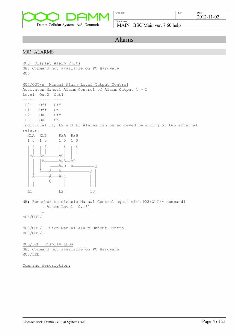
Damm Cellular Systems A/S, Denmark MAIN BSC Main ver. 7.60 help
Doc. No. Rev. Date
Description
2012-11-02
Alarms
M03 ALARMS
M03 Display Alarm Ports
NB: Command not available on PC Hardware
M03
M03/OUT/n Manual Alarm Level Output Control
Activates Manual Alarm Control of Alarm Output 1 + 2
Level Out2 Out1
----- ---- ----
L0: Off Off
L1: Off On
L2: On Off
L3: On On
Individual L1, L2 and L3 Alarms can be achieved by wiring of two external
relays:
K1A K1B K2A K2B
1 0 1 0 1 0 1 0
¿ ¿ ¿ ¿
ÀÅ ÅÅ ÅÙ
À Å Å ÅÙ
Å Ù À ¿
À Å Å ¿
À Å Å ¿
Ù
L1 L2 L3
NB: Remember to disable Manual Control again with M03/OUT/- command!
Alarm Level (0..3)
M03/OUT/.
M03/OUT/- Stop Manual Alarm Output Control
M03/OUT/-
M03/LED Display LEDs
NB: Command not available on PC Hardware
M03/LED
Command description:
Page 4 of 21Licensed user: Damm Cellular Systems A/S
Damm Cellular Systems A/S, Denmark MAIN BSC Main ver. 7.60 help
Doc. No. Rev. Date
Description
2012-11-02
Network Settings
M06 DISPLAY NETWORK PARAMETERS
M06 Display Network parameters
M06
Command description:
Page 5 of 21Licensed user: Damm Cellular Systems A/S
Damm Cellular Systems A/S, Denmark MAIN BSC Main ver. 7.60 help
Doc. No. Rev. Date
Description
2012-11-02
Date/Time
M07 DISPLAY DATE AND TIME
M07 Display date and time
M07
M07/S Display date/time status
M07/S
Command description:
Page 6 of 21Licensed user: Damm Cellular Systems A/S

Damm Cellular Systems A/S, Denmark MAIN BSC Main ver. 7.60 help
Doc. No. Rev. Date
Description
2012-11-02
PS421 Status
M16 PS421 STATUS
M16 Display PS421 Status
Displays status of the local connected PS421
NB: Only available on BSC421 if if PS421 is configured!
M16
M16/AL Display PS421 Alarm Flags
Displays Alarm Flags for the local connected PS421
NB: Only available on BSC421 if if PS421 is configured!
M16/AL
Command description:
Page 7 of 21Licensed user: Damm Cellular Systems A/S

Damm Cellular Systems A/S, Denmark MAIN BSC Main ver. 7.60 help
Doc. No. Rev. Date
Description
2012-11-02
Debug Queue/File
M46 DEBUG QUEUE/FILE
M46 Display Debug Queue/File status
M46
M46/C Clear Debug Queue
M46/C
M46/S Save Debug Queue in File
Debug is save in ...\Data\Debug.txt
M46/S
Command description:
Page 8 of 21Licensed user: Damm Cellular Systems A/S

Damm Cellular Systems A/S, Denmark MAIN BSC Main ver. 7.60 help
Doc. No. Rev. Date
Description
2012-11-02
GUI OM Command
M50 GUI OM COMMAND
M50 Display Last GUI OM Command/Response
To be used for Software development only
M50
M50/cc..c Execute GUI OM Command
Writes the OM Command to the GUI Shared Memory.
Multicommands separated with the '|' character are supported.
As '|' however can not been sent as it will be interpreted of the OM Program,
the character '^' shall be used instead. The OM F50 command interpreter will
modify
'^' to '|' before it is written.
To be used for Software development only
OM Command
M50/.........................................................................
Command description:
Page 9 of 21Licensed user: Damm Cellular Systems A/S

Damm Cellular Systems A/S, Denmark MAIN BSC Main ver. 7.60 help
Doc. No. Rev. Date
Description
2012-11-02
CPLD
M62 CPLD
M62 Display CPLD Version
M62
M62/HWSIG Display CPLD Hardware Signature
M62/HWSIG
M62/RAM Read CPLD Test RAM
M62/RAM
M62/RAM/hhhh Write/Read CPLD Test RAM
Value to write (0000..hhhh hex)
M62/RAM/....
M62/INPORT Display Input Port
M62/INPORT
M62/ALPORT Display Alarm Port
M62/ALPORT
Command description:
Page 10 of 21Licensed user: Damm Cellular Systems A/S
Damm Cellular Systems A/S, Denmark MAIN BSC Main ver. 7.60 help
Doc. No. Rev. Date
Description
2012-11-02
CPU load
M66 CPU LOAD COMMAND
M66 Display CPU load
M66
M66/C Clear CPU Load Peak Hold
M66/C
M66/T Display 1msec. Timer
M66/T
M66/Q Display QPC Timer
M66/Q
Command description:
Page 11 of 21Licensed user: Damm Cellular Systems A/S

Damm Cellular Systems A/S, Denmark MAIN BSC Main ver. 7.60 help
Doc. No. Rev. Date
Description
2012-11-02
PS421 Program Download
M68 PS421 PROGRAM DOWNLOAD
M68 Display Program Download Status
M68
M68/PS421 Display PS421 Program Download Status
NB: Command only available with BSC421 Hardware
M68/PS421
M68/PS421/+ Start PS421 Program Download
1) Reads ...\PGM\PS421\PS421.HEX file from disk
2) Sends 68/BOOT command to PS421 to restart in boot mode
3) Dowloads Hex Records to PS421
4) Restarts PS421 again
NB: Boot Part of PS421 software is NOT updated.
Boot version can be displayed with the PS421 '68' command.
NB: Command only available with BSC421 Hardware
M68/PS421/+
Command description:
Page 12 of 21Licensed user: Damm Cellular Systems A/S
Damm Cellular Systems A/S, Denmark MAIN BSC Main ver. 7.60 help
Doc. No. Rev. Date
Description
2012-11-02
I/O Memory
M69 I/O MEMORY
M69 Display I/O Memory Configuration
M69
M69/hhhh/1 Read I/O Memory Byte
Address Offset (0000..hhhh hex)
M69/..../1
M69/hhhh/2 Read I/O Memory 16-bit word
Address Offset (0000..hhhh hex)
M69/..../2
M69/hhhh/hh Write I/O Memory Byte
Address Offset (0000..hhhh hex)
Value to write (00..FF hex)
M69/..../..
M69/hhhh/hhhh Write I/O Memory 16-bit word
Address Offset (0000..hhhh hex)
Value to write (0000..FFFF hex)
M69/..../....
Command description:
Page 13 of 21Licensed user: Damm Cellular Systems A/S

Damm Cellular Systems A/S, Denmark MAIN BSC Main ver. 7.60 help
Doc. No. Rev. Date
Description
2012-11-02
System configuration
M70 MAIN CONFIGURATION
M70 Display last File Save result
M70
M70/SAVE Save Main Configuration
Note that Main Configuration changes are saved automatically
M70/SAVE
Command description:
Page 14 of 21Licensed user: Damm Cellular Systems A/S
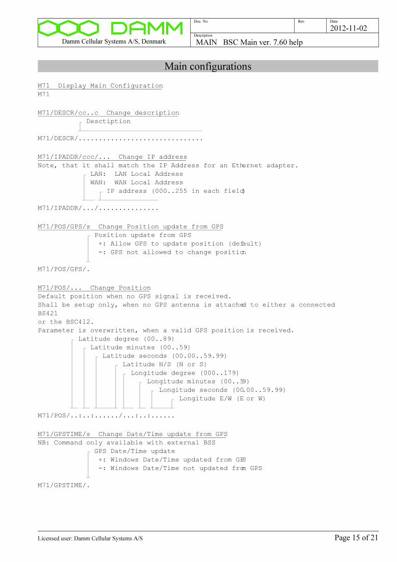
Damm Cellular Systems A/S, Denmark MAIN BSC Main ver. 7.60 help
Doc. No. Rev. Date
Description
2012-11-02
Main configurations
M71 Display Main Configuration
M71
M71/DESCR/cc..c Change description
Desctiption
M71/DESCR/...............................
M71/IPADDR/ccc/... Change IP address
Note, that it shall match the IP Address for an Ethernet adapter.
LAN: LAN Local Address
WAN: WAN Local Address
IP address (000..255 in each field)
M71/IPADDR/.../...............
M71/POS/GPS/s Change Position update from GPS
Position update from GPS
+: Allow GPS to update position (default)
-: GPS not allowed to change position
M71/POS/GPS/.
M71/POS/... Change Position
Default position when no GPS signal is received.
Shall be setup only, when no GPS antenna is attached to either a connected
BS421
or the BSC412.
Parameter is overwritten, when a valid GPS position is received.
Latitude degree (00..89)
Latitude minutes (00..59)
Latitude seconds (00.00..59.99)
Latitude N/S (N or S)
Longitude degree (000..179)
Longitude minutes (00..59)
Longitude seconds (00.00..59.99)
Longitude E/W (E or W)
M71/POS/..:..:....../...:..:......
M71/GPSTIME/s Change Date/Time update from GPS
NB: Command only available with external BSS
GPS Date/Time update
+: Windows Date/Time updated from GPS
-: Windows Date/Time not updated from GPS
M71/GPSTIME/.
Page 15 of 21Licensed user: Damm Cellular Systems A/S
Damm Cellular Systems A/S, Denmark MAIN BSC Main ver. 7.60 help
Doc. No. Rev. Date
Description
2012-11-02
PS421 configuration
M76 Display PS421 Configuration
NB: Only available for BSC421!
M76
M76/PS421 Setup PS421 configuration
NB: Only available for BSC421!
M76/PS421
M76/REMOVE Remove PS configuration
NB: Only available for BSC421!
M76/REMOVE
M76/PSADDR/nn Change PS421 Address
NB: Only available for BSC421!
PS421 Address (11..47)
M76/PSADDR/..
M76/BSCn/... Change BSC IP address
IP Addresses of the BSC for PS421 status forwarding
1: BSC1
2: BSC2
IP address (000..255 in each field)
M76/BSC./...............
Page 16 of 21Licensed user: Damm Cellular Systems A/S
Damm Cellular Systems A/S, Denmark MAIN BSC Main ver. 7.60 help
Doc. No. Rev. Date
Description
2012-11-02
Factory configuration commands
M90 Display Factory Configuration status
M90
M90/FACTORYUNLOCK Select Factory Configuration unlock
UNLOCK
M90/FACTORY......
M90- Deselect Factory Configuration unlock
M90-
M90/SAVE Save Factory Configuration
Note, that all Factory Configuration changes
are saved automatically
M90/SAVE
Page 17 of 21Licensed user: Damm Cellular Systems A/S
Damm Cellular Systems A/S, Denmark MAIN BSC Main ver. 7.60 help
Doc. No. Rev. Date
Description
2012-11-02
Hardware Versions
M91 HARDWARE VERSIONS
M91 Display Hardware Versions
M91
M91/ITEM/cc..c Change item number
Item number
M91/ITEM/...............
M91/SER/cc..c Change serial number
Serial number
M91/SER/........
M91/VER/n.nn Change version number
Version number
M91/VER/....
M91/REV/n Change revision number
Revision number (00..99)
M91/REV/..
Command description:
Page 18 of 21Licensed user: Damm Cellular Systems A/S
Damm Cellular Systems A/S, Denmark MAIN BSC Main ver. 7.60 help
Doc. No. Rev. Date
Description
2012-11-02
BSC412 Factory Configuration
M92 BSC412 FACTORY CONFIGURATION
M92 Display BSC412 Factory Configuration
M92
M92/GPSRX/c Change GPS RX type
GPS RX Type
3: iTrax03
6: IT600
M92/GPSRX/.
Command description:
Page 19 of 21Licensed user: Damm Cellular Systems A/S
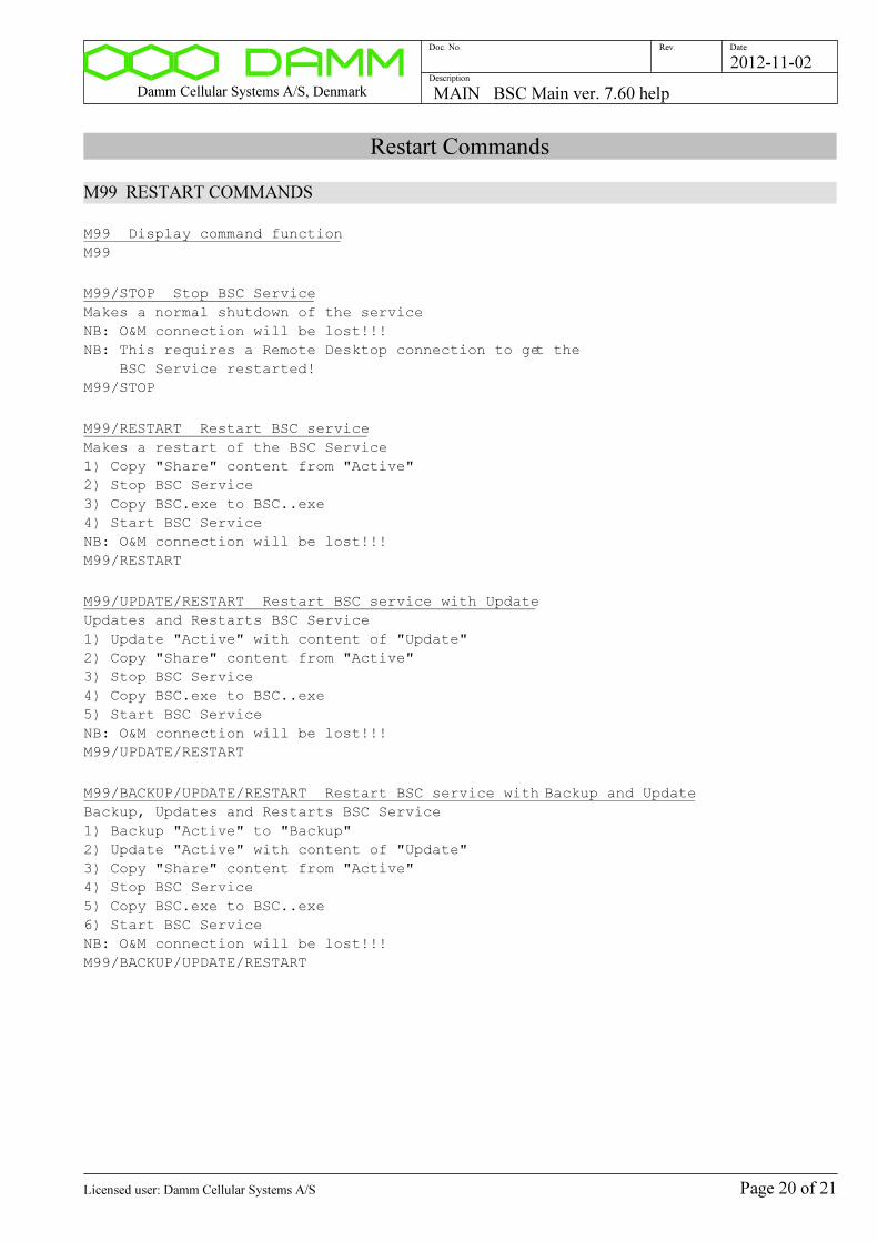
Damm Cellular Systems A/S, Denmark MAIN BSC Main ver. 7.60 help
Doc. No. Rev. Date
Description
2012-11-02
Restart Commands
M99 RESTART COMMANDS
M99 Display command function
M99
M99/STOP Stop BSC Service
Makes a normal shutdown of the service
NB: O&M connection will be lost!!!
NB: This requires a Remote Desktop connection to get the
BSC Service restarted!
M99/STOP
M99/RESTART Restart BSC service
Makes a restart of the BSC Service
1) Copy "Share" content from "Active"
2) Stop BSC Service
3) Copy BSC.exe to BSC..exe
4) Start BSC Service
NB: O&M connection will be lost!!!
M99/RESTART
M99/UPDATE/RESTART Restart BSC service with Update
Updates and Restarts BSC Service
1) Update "Active" with content of "Update"
2) Copy "Share" content from "Active"
3) Stop BSC Service
4) Copy BSC.exe to BSC..exe
5) Start BSC Service
NB: O&M connection will be lost!!!
M99/UPDATE/RESTART
M99/BACKUP/UPDATE/RESTART Restart BSC service with Backup and Update
Backup, Updates and Restarts BSC Service
1) Backup "Active" to "Backup"
2) Update "Active" with content of "Update"
3) Copy "Share" content from "Active"
4) Stop BSC Service
5) Copy BSC.exe to BSC..exe
6) Start BSC Service
NB: O&M connection will be lost!!!
M99/BACKUP/UPDATE/RESTART
Page 20 of 21Licensed user: Damm Cellular Systems A/S
Damm Cellular Systems A/S, Denmark MAIN BSC Main ver. 7.60 help
Doc. No. Rev. Date
Description
2012-11-02
M99/RESTORE/RESTART Restart BSC service with Restore
Restores and Restarts BSC Service
1) Restores "Backup" to "Active"
2) Copy "Share" content from "Active"
3) Stop BSC Service
4) Copy BSC.exe to BSC..exe
5) Start BSC Service
NB: O&M connection will be lost!!!
M99/RESTORE/RESTART
Command description:
Page 21 of 21Licensed user: Damm Cellular Systems A/S
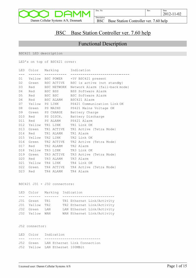
Damm Cellular Systems A/S, Denmark BSC Base Station Controller ver. 7.60 help
Doc. No. Rev. Date
Description
2012-11-02
BSC Base Station Controller ver. 7.60 help
Functional Description
BSC421 LED description
LED's on top of BSC421 cover:
LED Color Marking Indication
--- ------ ----------- ------------------------------
D1 Yellow BSC POWER +5V BSC421 present
D2 Green BSC ACTIVE BSC is active (not standby)
D3 Red BSC NETWORK Network Alarm (fall-back mode)
D4 Red BSC BSS BSS Software Alarm
D5 Red BSC BSC BSC Software Alarm
D6 Red BSC ALARM BSC421 Alarm
D7 Yellow PS LINK PS421 Communication Link OK
D8 Green PS MAINS PS421 Mains Voltage OK
D9 Green PS CHARGE Battery Charge
D10 Red PS DISCH. Battery Discharge
D11 Red PS ALARM PS421 Alarm
D12 Yellow TR1 LINK TR1 Link OK
D13 Green TR1 ACTIVE TR1 Active (Tetra Mode)
D14 Red TR1 ALARM TR1 Alarm
D15 Yellow TR2 LINK TR2 Link OK
D16 Green TR2 ACTIVE TR2 Active (Tetra Mode)
D17 Red TR2 ALARM TR2 Alarm
D18 Yellow TR3 LINK TR3 Link OK
D19 Green TR3 ACTIVE TR3 Active (Tetra Mode)
D20 Red TR3 ALARM TR3 Alarm
D21 Yellow TR4 LINK TR4 Link OK
D22 Green TR4 ACTIVE TR4 Active (Tetra Mode)
D23 Red TR4 ALARM TR4 Alarm
BSC421 J31 + J32 connectors:
LED Color Marking Indication
--- ------ ------- --------------------------
J31 Green TR1 TR1 Ethernet Link/Activity
J31 Yellow TR2 TR2 Ethernet Link/Activity
J32 Green LAN LAN Ethernet Link/Activity
J32 Yellow WAN WAN Ethernet Link/Activity
J52 connector:
LED Color Indication
--- ------ ----------------------------
J52 Green LAN Ethernet Link Connection
J52 Yellow LAN Ethernet 100MBit
Page 1 of 15Licensed user: Damm Cellular Systems A/S
Damm Cellular Systems A/S, Denmark BSC Base Station Controller ver. 7.60 help
Doc. No. Rev. Date
Description
2012-11-02
General commands
F00 DISPLAY SOFTWARE VERSION
F00 Display Software Version
F00
F00/BSC Display OM Red. BSC Connection status
F00/BSC
Command description:
Page 2 of 15Licensed user: Damm Cellular Systems A/S
Damm Cellular Systems A/S, Denmark BSC Base Station Controller ver. 7.60 help
Doc. No. Rev. Date
Description
2012-11-02
BSC Activation Control
F02 BSC ACTIVATION CONTROL
F02 Display BSC Activation Status
F02
F02/ACTIVATE BSC Activation Request
Sends Activation Request to other BSC
F02/ACTIVATE
F02/STANDBY/s Change Forced BSC Standby
+: Forced Standby
-: Normal
F02/STANDBY/.
Command description:
Page 3 of 15Licensed user: Damm Cellular Systems A/S

Damm Cellular Systems A/S, Denmark BSC Base Station Controller ver. 7.60 help
Doc. No. Rev. Date
Description
2012-11-02
Alarms
F03 ALARMS
F03 Display BS Alarm state
F03
F03/C Clear all BS alarms
F03/C
Command description:
Page 4 of 15Licensed user: Damm Cellular Systems A/S
Damm Cellular Systems A/S, Denmark BSC Base Station Controller ver. 7.60 help
Doc. No. Rev. Date
Description
2012-11-02
Radio Cell Status
F13 RADIO CELL STATUS
F13 Display Radio Cell Status
F13
Command description:
Page 5 of 15Licensed user: Damm Cellular Systems A/S

Damm Cellular Systems A/S, Denmark BSC Base Station Controller ver. 7.60 help
Doc. No. Rev. Date
Description
2012-11-02
Power Supply Status
F14 POWER SUPPLY STATUS
F14 Display Power Supply Status
F14
Command description:
Page 6 of 15Licensed user: Damm Cellular Systems A/S
Damm Cellular Systems A/S, Denmark BSC Base Station Controller ver. 7.60 help
Doc. No. Rev. Date
Description
2012-11-02
TR Status
F15 TR STATUS
F15 Display TR Status
F15
F15/c Display TR Status
F: Frequencies/Power
P: GPS Positions
V: Versions
L: Frequency and Power Limits
E: External Alarms
F15/.
F15/nn/A Display TR Alarm Flags
TR Address (11..48)
F15/../A
Command description:
Page 7 of 15Licensed user: Damm Cellular Systems A/S
Damm Cellular Systems A/S, Denmark BSC Base Station Controller ver. 7.60 help
Doc. No. Rev. Date
Description
2012-11-02
PS411 Status
F16 PS STATUS
F16 Display PS Status
F16
F16/nn Display PS Status
PS Address (11..47)
F16/..
F16/AL Display PS411 Alarm Flags
F16/AL
F16/REC Display PS411 Rectifier status
F16/REC
F16/OUT Display PS411 +14V/+26V status
F16/OUT
F16/LED Display PS411 LED status
F16/LED
Command description:
Page 8 of 15Licensed user: Damm Cellular Systems A/S

Damm Cellular Systems A/S, Denmark BSC Base Station Controller ver. 7.60 help
Doc. No. Rev. Date
Description
2012-11-02
BSS Message test queue
F63 BSS MESSAGE TEST QUEUE
F63 Display BSS Link Status
F63
F63/N Display next BSS message
F63/N
F63/N+ Display next BSS message extended
F63/N+
F63/S Set BSS message test queue to start
F63/S
F63/C Clear BSS message test queue
F63/C
F63/s BSS Message suppression
+: Display all BSS messages
-: Suppress some BSS messages (default)
F63/.
F63/hh/hh..hh Send Message to BSS
Message ID (00..FF hex)
Payload (hex)
0 02 04 06 08 10 12 14 16 18 20 22 24 26 28 30 32 34
ÿ ¿ ¿ ¿ ¿ ¿ ¿ ¿ ¿ ¿ ¿ ¿ ¿ ¿ ¿ ¿ ¿ ¿ ¿ ¿ ¿ ¿ ¿ ¿ ¿ ¿ ¿ ¿ ¿ ¿ ¿ ¿ ¿ ¿ ¿
F63/../......................................................................
Command description:
Page 9 of 15Licensed user: Damm Cellular Systems A/S

Damm Cellular Systems A/S, Denmark BSC Base Station Controller ver. 7.60 help
Doc. No. Rev. Date
Description
2012-11-02
UDP Message test queue
F64 UDP MESSAGE TEST QUEUE
F64 Display UDP Link Status
F64
F64/N Display next UDP message
F64/N
F64/N+ Display next UDP message extended
F64/N+
F64/S Set UDP message test queue to start
F64/S
F64/C Clear UDP message test queue
F64/C
F64/s UDP Message suppression
+: Display all UDP messages
-: Suppress some UDP messages (default)
F64/.
F64/hh/hh..hh Send Message to Redundant BSC
Message ID (00..FF hex)
Payload (hex)
0 02 04 06 08 10 12 14 16 18 20 22 24 26 28 30 32 34
ÿ ¿ ¿ ¿ ¿ ¿ ¿ ¿ ¿ ¿ ¿ ¿ ¿ ¿ ¿ ¿ ¿ ¿ ¿ ¿ ¿ ¿ ¿ ¿ ¿ ¿ ¿ ¿ ¿ ¿ ¿ ¿ ¿ ¿ ¿
F64/../......................................................................
Command description:
Page 10 of 15Licensed user: Damm Cellular Systems A/S
Damm Cellular Systems A/S, Denmark BSC Base Station Controller ver. 7.60 help
Doc. No. Rev. Date
Description
2012-11-02
TR Message test queue
F65 TR MESSAGE TEST QUEUE
F65 Display TR Link Status
F65
F65/TCP Display TR TCP Connections
F65/TCP
F65/N Display next TR message
F65/N
F65/N+ Display next TR message extended
F65/N+
F65/S Set TR message test queue to start
F65/S
F65/C Clear TR message test queue
F65/C
F65/s TR Message suppression
+: Display all TR messages
-: Suppress some TR messages (default)
F65/.
F65/nn/hh/hh..hh Send Message to TR
TR Address (11..48)
Message ID (00..FF hex)
Payload (hex)
0 02 04 06 08 10 12 14 16 18 20 22 24 26 28 30 32
34
ÿ ¿ ¿ ¿ ¿ ¿ ¿ ¿ ¿ ¿ ¿ ¿ ¿ ¿ ¿ ¿ ¿ ¿ ¿ ¿ ¿ ¿ ¿ ¿ ¿ ¿ ¿ ¿ ¿ ¿ ¿ ¿ ¿ ¿ ¿
F65/../../.....................................................................
.
Command description:
Page 11 of 15Licensed user: Damm Cellular Systems A/S

Damm Cellular Systems A/S, Denmark BSC Base Station Controller ver. 7.60 help
Doc. No. Rev. Date
Description
2012-11-02
BSC configuration
F70 BSC CONFIGURATION
F70 Display last File Save result
F70
F70/SAVE Save BSC Configuration
Note that BSC Configuration changes are saved automatically
F70/SAVE
Command description:
Page 12 of 15Licensed user: Damm Cellular Systems A/S

Damm Cellular Systems A/S, Denmark BSC Base Station Controller ver. 7.60 help
Doc. No. Rev. Date
Description
2012-11-02
System configurations
F71 Display Common Configurations
F71
F71/CNFG/+ Activate BSC
F71/CNFG/+
F71/CNFG/- Deactivate BSC
F71/CNFG/-
F71/BSCNO/n Change BSC Number
BSC Number
1: BSC1
2: BSC2
F71/BSCNO/.
F71/REDBSC/s Change Redundant BSC Selection
+: Select Redundant BSC
-: Deselect Redundant BSC
F71/REDBSC/.
F71/REDBSC/... Change Redundant BSC IP Address
IP address (000..255 in each field)
F71/REDBSC/...............
F71/BSS/... Change BSS IP Address
NB: Command only available in OEM Base Stations
IP address (000..255 in each field)
F71/BSS/...............
F71/BSS/nnnnn Change BSS Remote Port
NB: Command only available in OEM Base Stations
IP Port (Default: 42395)
F71/BSS/.....
F71/BSS/c Change BSS Message Protocol
TCP Server is the default recommended protocol
NB: Command only available in OEM Base Stations
BSS Message Protocol
U: UDP
S: TCP Server (recommended)
C: TCP Client
F71/BSS/.
Page 13 of 15Licensed user: Damm Cellular Systems A/S
Damm Cellular Systems A/S, Denmark BSC Base Station Controller ver. 7.60 help
Doc. No. Rev. Date
Description
2012-11-02
TR Configuration
F75 Display TR Configuration
F75
F75/nn/TR412 Add TR412 Transceiver
TR Address (11..48)
F75/../TR412
F75/nn/TR421 Add TR421 Transceiver
TR Address (11..48)
F75/../TR421
F75/nn/REMOVE Remove TR
TR Address (11..48)
F75/../REMOVE
Page 14 of 15Licensed user: Damm Cellular Systems A/S
Damm Cellular Systems A/S, Denmark BSC Base Station Controller ver. 7.60 help
Doc. No. Rev. Date
Description
2012-11-02
PS Configuration
F76 Display PS Configuration
F76
F76/nn/PS411 Add PS411 Power Supply
PS Address (11..47)
F76/../PS411
F76/nn/PS421 Add PS421 Power Supply
PS Address (11..47)
F76/../PS421
F76/nn/REMOVE Remove PS
PS Address (11..47)
F76/../REMOVE
Page 15 of 15Licensed user: Damm Cellular Systems A/S
Damm Cellular Systems A/S, Denmark BSS Base Station Switch ver. 7.60 help
Doc. No. Rev. Date
Description
2012-11-02
BSS Base Station Switch ver. 7.60 help
Software Versions:
S00 SOFTWARE VERSIONS
S00 Display software version
S00
S00/C Display BSS compiler options
S00/C
Command description:
Page 1 of 69Licensed user: Damm Cellular Systems A/S

Damm Cellular Systems A/S, Denmark BSS Base Station Switch ver. 7.60 help
Doc. No. Rev. Date
Description
2012-11-02
License Dongle:
S04 LICENSE DONGLE
S04 Display License Dongle Settings
Displays the settings read from dongle at application startup
NB: Only the Node BSC details are showed
S04
S04/I Display License Dongle Info
Displays the info read from dongle at application startup
S04/I
S04/D Display License Dongle Memory in Decimal
Displays the info read from dongle at application startup
S04/D
S04/H Display License Dongle Memory in Hex
Displays the info read from dongle at application startup
S04/H
Command description:
Page 2 of 69Licensed user: Damm Cellular Systems A/S
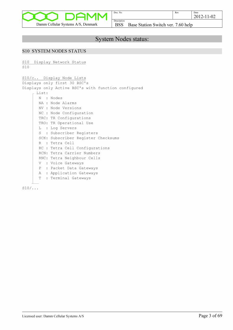
Damm Cellular Systems A/S, Denmark BSS Base Station Switch ver. 7.60 help
Doc. No. Rev. Date
Description
2012-11-02
System Nodes status:
S10 SYSTEM NODES STATUS
S10 Display Network Status
S10
S10/c.. Display Node Lists
Displays only first 30 BSC's
Displays only Active BSC's with function configured
List:
N : Nodes
NA : Node Alarms
NV : Node Versions
NC : Node Configuration
TRC: TR Configurations
TRO: TR Operational Use
L : Log Servers
S : Subscriber Registers
SCK: Subscriber Register Checksums
R : Tetra Cell
RC : Tetra Cell Configurations
RCN: Tetra Carrier Numbers
RNC: Tetra Neighbour Cells
V : Voice Gateways
P : Packet Data Gateways
A : Application Gateways
T : Terminal Gateways
S10/...
Page 3 of 69Licensed user: Damm Cellular Systems A/S

Damm Cellular Systems A/S, Denmark BSS Base Station Switch ver. 7.60 help
Doc. No. Rev. Date
Description
2012-11-02
S10/nnn/nn/s/c.. Display Node Lists
Displays only Active BSC's
First Node Number (001..NodeMax)
Max. number of Lines (1..50)
+: Display all BSC's
-: Display only active BSC's with function configured
List:
N : Nodes
NA : Node Alarms
NV : Node Versions
NC : Node Configuration
TRC: TR Configurations
TRO: TR Operational Use
L : Log Servers
S : Subscriber Registers
SCK: Subscriber Register Checksums
R : Tetra Cells
RC : Tetra Cell Configurations
RCN: Tetra Carrier Numbers
RNC: Tetra Neighbour Cells
V : Voice Gateways
P : Packet Data Gateways
A : Application Gateways
T : Terminal Gateways
S10/.../.././...
S10/nnn/c/c.. Display one Node BSC
Node Number (001..NodeMax)
BSC:
A: Active BSC
1: BSC1
2: BSC2
Parameter:
N : Nodes
NI : Node Indicators
TR : TR Use
S : Subscriber Register
R : Tetra Cell
RCN: Tetra Carrier Numbers
RNC: Tetra Neighbour Cells
V : Voice Gateway
P : Packet Data Gateway
A : Application Gateway
T : Terminal Gateway
S10/..././...
S10/CLEAR Clear Node Message Sequence Error Counters
S10/CLEAR
Command description:
Page 4 of 69Licensed user: Damm Cellular Systems A/S
Damm Cellular Systems A/S, Denmark BSS Base Station Switch ver. 7.60 help
Doc. No. Rev. Date
Description
2012-11-02
Log Server status:
S10/LS LOG SERVER STATUS
S10/LS Display Log Servers
S10/LS
S10/LS/c.. Display Log Server Lists
VER: Software Versions/Dates
IP : IP Addresses
S10/LS/...
S10/LS/CLEAR Clear Log Server Message Sequence Error Counters
S10/LS/CLEAR
S10/QUE Display Node Output Queues
S10/QUE
Command description:
Page 5 of 69Licensed user: Damm Cellular Systems A/S

Damm Cellular Systems A/S, Denmark BSS Base Station Switch ver. 7.60 help
Doc. No. Rev. Date
Description
2012-11-02
Node Status:
S11 NODE STATUS
S11 Display Node Alarm Status
S11
Command description:
Page 6 of 69Licensed user: Damm Cellular Systems A/S

Damm Cellular Systems A/S, Denmark BSS Base Station Switch ver. 7.60 help
Doc. No. Rev. Date
Description
2012-11-02
Tetra Cell Status:
S12 TETRA CELL STATUS
S12 Display Tetra Cell Status
S12
S12/CNT Display Tetra Timeslot Counts
S12/CNT
S12/TS Display Tetra Timeslot Status
S12/TS
S12/TS/cc/s Tetra Timeslot Operator Blocking/Deblocking
Device:
11..48: TR Address
QQ : Queue
Action:
+: Block Timeslot
-: Deblock Timeslot
S12/TS/../.
S12/TS/cc/n/s Tetra Timeslot Operator Blocking/Deblocking
Device:
11..48: TR Address
QQ : Queue
Timeslot Number (1..4 for TR, 1..2 for Queue)
Action:
+: Block Timeslot
-: Deblock Timeslot
S12/TS/.././.
S12/TR Display Tetra TR Status List
S12/TR
S12/NC Display Tetra Neighbour Cell List
S12/NC
S12/PD Display Tetra Packet Data Counters
S12/PD
S12/PD/C Clear Tetra Packet Data Counters
S12/PD/C
Page 7 of 69Licensed user: Damm Cellular Systems A/S

Damm Cellular Systems A/S, Denmark BSS Base Station Switch ver. 7.60 help
Doc. No. Rev. Date
Description
2012-11-02
S12/CCK/c Tetra CCK change request
Requests immediate update of CCK for all mobiles
with Air Interface Encryption.
The Key change is about 6 seconds after the command.
See also S12 command
CCK change request kind
U: Unannounced
A: Announced
S12/CCK/.
Command description:
Page 8 of 69Licensed user: Damm Cellular Systems A/S

Damm Cellular Systems A/S, Denmark BSS Base Station Switch ver. 7.60 help
Doc. No. Rev. Date
Description
2012-11-02
Voice Gateway Status:
S13 VOICE GATEWAY STATUS
S13 Display Voice Gateway Status
S13
S13/L Display Voice Gateway Status List
S13/L
S13/nnn Display Voice Gateway Instance Status
Voice Gateway Instance Number (000..nnn)
S13/...
Command description:
Page 9 of 69Licensed user: Damm Cellular Systems A/S

Damm Cellular Systems A/S, Denmark BSS Base Station Switch ver. 7.60 help
Doc. No. Rev. Date
Description
2012-11-02
Packet Data Gateway Status:
S14 PACKET DATA GATEWAY STATUS
S14 Display Packet Data Gateway Status
S14
S14/N Display Packet Data Gateway Counters
S14/N
S14/C Clear Packet Data Gateway Counters
S14/C
Command description:
Page 10 of 69Licensed user: Damm Cellular Systems A/S
Damm Cellular Systems A/S, Denmark BSS Base Station Switch ver. 7.60 help
Doc. No. Rev. Date
Description
2012-11-02
Application Gateway Status:
S15 APPLICATION GATEWAY STATUS
S15 Display Application Gateway Status
S15
S15/L Display Application Gateway Connection List
S15/L
S15/IX/nnn Display Application Gateway Connection (Index)
Index (000..nnn)
S15/IX/...
S15/SSI/nnnnnnnn Display Application Gateway Instance (SSI)
SSI (00000001..16777215)
S15/SSI/........
S15/USERNO/nn..n Display Application Gateway Connection (User Number)
User Number (0..9999999)
S15/USERNO/.......
Command description:
Page 11 of 69Licensed user: Damm Cellular Systems A/S

Damm Cellular Systems A/S, Denmark BSS Base Station Switch ver. 7.60 help
Doc. No. Rev. Date
Description
2012-11-02
Terminal Gateway Status:
S16 TERMINAL GATEWAY STATUS
S16 Display Terminal Gateway Status
S16
S16/L Display Terminal Gateway Connection List
S16/L
S16/IX/nnn Display Terminal Gateway Connection (Index)
Index (000..nnn)
S16/IX/...
S16/SSI/nnnnnnnn Display Terminal Gateway Connection (SSI)
SSI (00000001..16777215)
S16/SSI/........
S16/USERNO/nn..n Display Terminal Gateway Connection (User Number)
User Number (0..9999999)
S16/USERNO/.......
Command description:
Page 12 of 69Licensed user: Damm Cellular Systems A/S
Damm Cellular Systems A/S, Denmark BSS Base Station Switch ver. 7.60 help
Doc. No. Rev. Date
Description
2012-11-02
Subscriber Register:
S20 Display Subscriber Register
S20
S20/S Display Subscriber Register Status
S20/S
S20/CNT Display Subscriber Register Counts
S20/CNT
S20/CKS Display Subscriber Register Checksums
S20/CKS
S20/DL Display Master Subscriber Register Download status
Displays the status of the Master Subscriber Register
S20/DL
S20/REG Display Subscriber Registration Update status
Displays status of Subscriber Registration Update
Runs on all active BSC's to send Registration status of all
registered SSI on this Node to other nodes.
S20/REG
S20/REG/+ Start Subscriber Registration Update
Used to manually start a complete update of all other Nodes
with registration information of regstered SSI's on this Node.
NB: Command is for test purposes only.
S20/REG/+
S20/TEI/nnn..n Find TEI Terminal Equipment Identity
TEI (15 digits 0..9, A..F)
S20/TEI/...............
S20/SIM/nnn..n Find SIM Card Identity
SIM (20 digits 0..9, A..F)
S20/SIM/....................
S20/SECSET Display Security Set Renew Status
Displays the status of Security Set renewal
NB: Requires Key Register active and Subscriber Register not in slave mode
S20/SECSET
Page 13 of 69Licensed user: Damm Cellular Systems A/S
Damm Cellular Systems A/S, Denmark BSS Base Station Switch ver. 7.60 help
Doc. No. Rev. Date
Description
2012-11-02
S20/SECSET/RENEW Start Security Set Renewal
Starts renewal of the Security Set for all Individual SSI.
The new Security Sets will be automatically replicated to all Nodes
1) If SIM is setup, SIM will be used for Key search
2) Else if TEI is setup, TEI will be used for Key search
3) Else no renewal is done
NB: Requires Key Register active and Subscriber Register not in slave mode
S20/SECSET/RENEW
S20/SAVE Save Subscriber Register to OM command file
Saved in "Subscr.txt" file in "Data" directory
S20/SAVE
S20/READ Read Subscriber Register from OM command file
Reads and executes "Subscr.txt" file in "Data" directory
Note, that it will add/change to the existing subscriber register.
The subscriber register can be cleaned before the read-in with the following
procedure:
1) Stop the BSC with Master Subscriber Register
2) Delete manually the files OrgV2.bin, ProfV2.bin and SubscrV2.bin
3) Restart the BSC
All Slaves will automatically be synchronized the the Master.
S20/READ
S20/CHECK Subscriber Register consistency check
S20/CHECK
S20/QUE Display Subscriber Register queues
S20/QUE
Page 14 of 69Licensed user: Damm Cellular Systems A/S

Damm Cellular Systems A/S, Denmark BSS Base Station Switch ver. 7.60 help
Doc. No. Rev. Date
Description
2012-11-02
Profile Register:
S21 Display Profile Register Status
S21
S21/nnnn Display Profile
Profile Number (0000..9999)
S21/....
S21/L/nnnn/snn/nn Display Profile list
Profile Number (0000..9999)
Line Offset (-50..+50)
Number of Lines (01..50)
S21/L/..../.../..
S21/nnnn/ADD/nnn/cc..c Add/Change Profile
The Home Organization number is used separate subscriber into isolated
organizations.
Note, that Home Organization value 0 has the special meaning "All" and is
intended to be used for e.g. the system operator.
Profile Number (0000..9999)
Home Organization (000..999) (0=All)
Description
S21/..../ADD/.../........................
S21/nnnn/ASSORG Display Associated Organizations
Profile Number (0000..9999)
S21/..../ASSORG
S21/nnnn/ASSORG/s Change use of Associated Organizations
Activates/deactivates the use of Associated Organizations
Profile Number (0000..9999)
Associated Organizations
+: Activate
-: Deactivate
S21/..../ASSORG/.
S21/nnnn/ASSORG/nnn/s Add/Remove Associated Organization
Maximum 16 Associated Organizations can setup
Profile Number (0000..9999)
Associated Organization Number (001..999)
Action
+: Add
-: Remove
S21/..../ASSORG/.../.
Page 15 of 69Licensed user: Damm Cellular Systems A/S
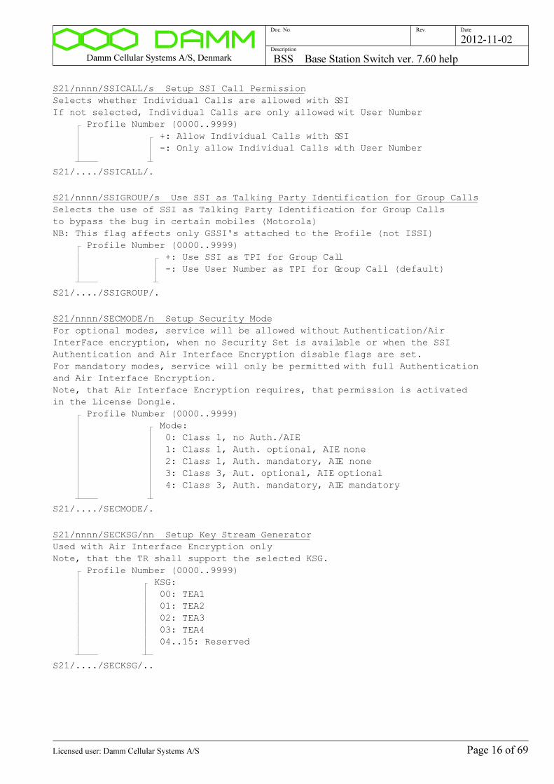
Damm Cellular Systems A/S, Denmark BSS Base Station Switch ver. 7.60 help
Doc. No. Rev. Date
Description
2012-11-02
S21/nnnn/SSICALL/s Setup SSI Call Permission
Selects whether Individual Calls are allowed with SSI
If not selected, Individual Calls are only allowed wit User Number
Profile Number (0000..9999)
+: Allow Individual Calls with SSI
-: Only allow Individual Calls with User Number
S21/..../SSICALL/.
S21/nnnn/SSIGROUP/s Use SSI as Talking Party Identification for Group Calls
Selects the use of SSI as Talking Party Identification for Group Calls
to bypass the bug in certain mobiles (Motorola)
NB: This flag affects only GSSI's attached to the Profile (not ISSI)
Profile Number (0000..9999)
+: Use SSI as TPI for Group Call
-: Use User Number as TPI for Group Call (default)
S21/..../SSIGROUP/.
S21/nnnn/SECMODE/n Setup Security Mode
For optional modes, service will be allowed without Authentication/Air
InterFace encryption, when no Security Set is available or when the SSI
Authentication and Air Interface Encryption disable flags are set.
For mandatory modes, service will only be permitted with full Authentication
and Air Interface Encryption.
Note, that Air Interface Encryption requires, that permission is activated
in the License Dongle.
Profile Number (0000..9999)
Mode:
0: Class 1, no Auth./AIE
1: Class 1, Auth. optional, AIE none
2: Class 1, Auth. mandatory, AIE none
3: Class 3, Aut. optional, AIE optional
4: Class 3, Auth. mandatory, AIE mandatory
S21/..../SECMODE/.
S21/nnnn/SECKSG/nn Setup Key Stream Generator
Used with Air Interface Encryption only
Note, that the TR shall support the selected KSG.
Profile Number (0000..9999)
KSG:
00: TEA1
01: TEA2
02: TEA3
03: TEA4
04..15: Reserved
S21/..../SECKSG/..
Page 16 of 69Licensed user: Damm Cellular Systems A/S
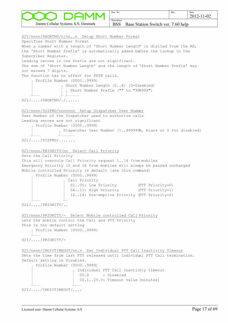
Damm Cellular Systems A/S, Denmark BSS Base Station Switch ver. 7.60 help
Doc. No. Rev. Date
Description
2012-11-02
S21/nnnn/SHORTNO/n/nn..n Setup Short Number Format
Specifies Short Number format
When a number with a length of 'Short Number Length' is dialled from the MS,
the 'Short Number Prefix' is automatically added before the lookup in the
Subscriber Register.
Leading zeroes in the Prefix are not significant.
The sum of 'Short Number Length' and the length of 'Short Number Prefix' may
not exceed 7 digits.
The function has no effect for PSTN calls.
Profile Number (0000..9999)
Short Number Length (0..6) (0=Disabled)
Short Number Prefix ("" to "999999")
S21/..../SHORTNO/./......
S21/nnnn/DISPNO/nnnnnnn Setup Dispatcher User Number
User Number of the Dispatcher used to authorize calls
Leading zeroes are not significant
Profile Number (0000..9999)
Dispatcher User Number (1..9999999, blank or 0 for disabled)
S21/..../DISPNO/.......
S21/nnnn/PRIORITY/nn Select Call Priority
Sets the Call Priority
This will overrule Call Priority request 1..14 from mobiles
Emergency Priority 15 and 16 from mobiles will always be passed unchanged
Mobile controlled Priority is default (see this command)
Profile Number (0000..9999)
Call Priority
01..05: Low Priority (PTT Priority=0)
06..11: High Priority (PTT Priority=1)
12..14: Pre-emptive Priority (PTT Priority=2)
S21/..../PRIORITY/..
S21/nnnn/PRIORITY/- Select Mobile controlled Call Priority
Lets the mobile control the Call and PTT Priority
This is the default setting
Profile Number (0000..9999)
S21/..../PRIORITY/-
S21/nnnn/INDIVTIMEOUT/nn.n Set Individual PTT Call Inactivity Timeout
Sets the time from last PTT released until Individual PTT Call termination.
Default setting is Disabled.
Profile Number (0000..9999)
Individuel PTT Call Inactivity timeout
00.0 : Disabled
00.1..25.0: Timeout value [minutes]
S21/..../INDIVTIMEOUT/....
Page 17 of 69Licensed user: Damm Cellular Systems A/S
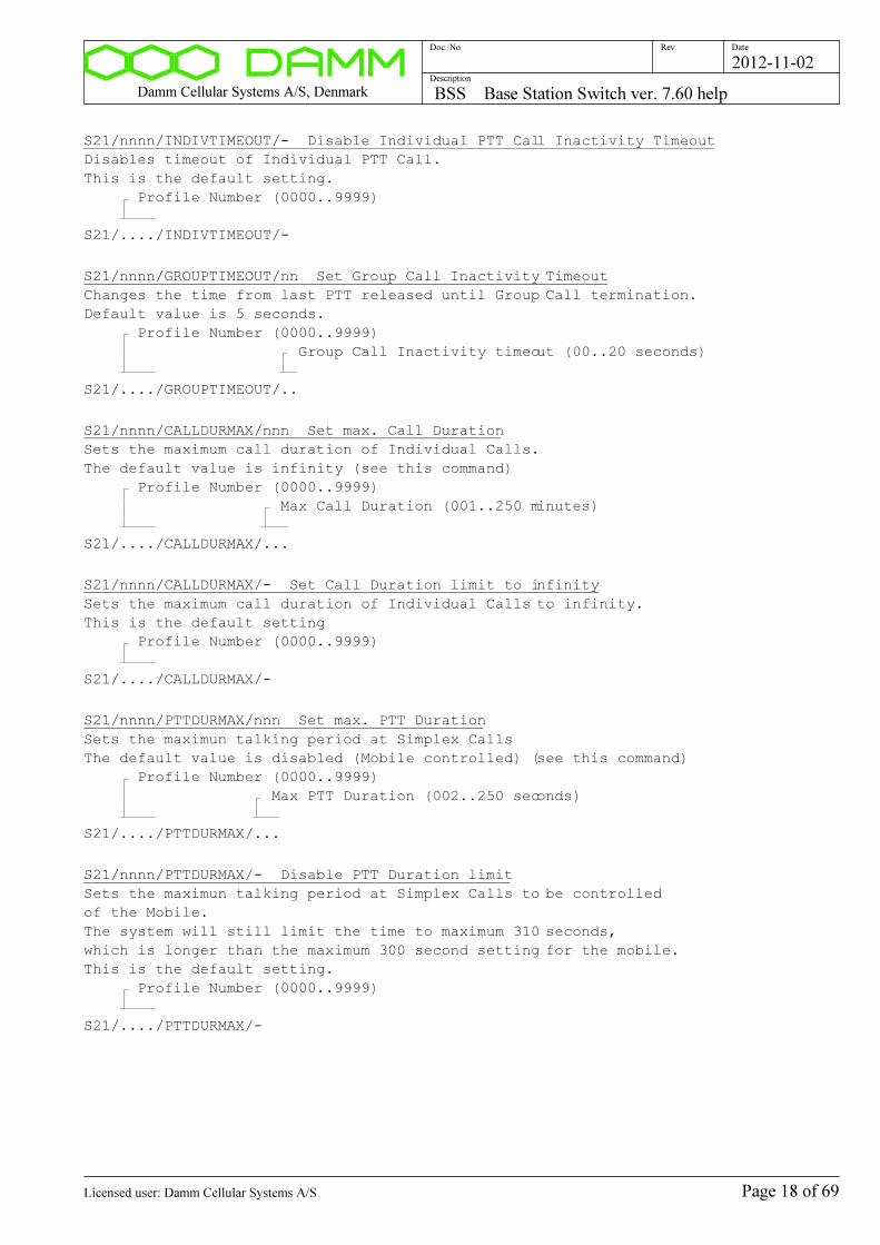
Damm Cellular Systems A/S, Denmark BSS Base Station Switch ver. 7.60 help
Doc. No. Rev. Date
Description
2012-11-02
S21/nnnn/INDIVTIMEOUT/- Disable Individual PTT Call Inactivity Timeout
Disables timeout of Individual PTT Call.
This is the default setting.
Profile Number (0000..9999)
S21/..../INDIVTIMEOUT/-
S21/nnnn/GROUPTIMEOUT/nn Set Group Call Inactivity Timeout
Changes the time from last PTT released until Group Call termination.
Default value is 5 seconds.
Profile Number (0000..9999)
Group Call Inactivity timeout (00..20 seconds)
S21/..../GROUPTIMEOUT/..
S21/nnnn/CALLDURMAX/nnn Set max. Call Duration
Sets the maximum call duration of Individual Calls.
The default value is infinity (see this command)
Profile Number (0000..9999)
Max Call Duration (001..250 minutes)
S21/..../CALLDURMAX/...
S21/nnnn/CALLDURMAX/- Set Call Duration limit to infinity
Sets the maximum call duration of Individual Calls to infinity.
This is the default setting
Profile Number (0000..9999)
S21/..../CALLDURMAX/-
S21/nnnn/PTTDURMAX/nnn Set max. PTT Duration
Sets the maximun talking period at Simplex Calls
The default value is disabled (Mobile controlled) (see this command)
Profile Number (0000..9999)
Max PTT Duration (002..250 seconds)
S21/..../PTTDURMAX/...
S21/nnnn/PTTDURMAX/- Disable PTT Duration limit
Sets the maximun talking period at Simplex Calls to be controlled
of the Mobile.
The system will still limit the time to maximum 310 seconds,
which is longer than the maximum 300 second setting for the mobile.
This is the default setting.
Profile Number (0000..9999)
S21/..../PTTDURMAX/-
Page 18 of 69Licensed user: Damm Cellular Systems A/S
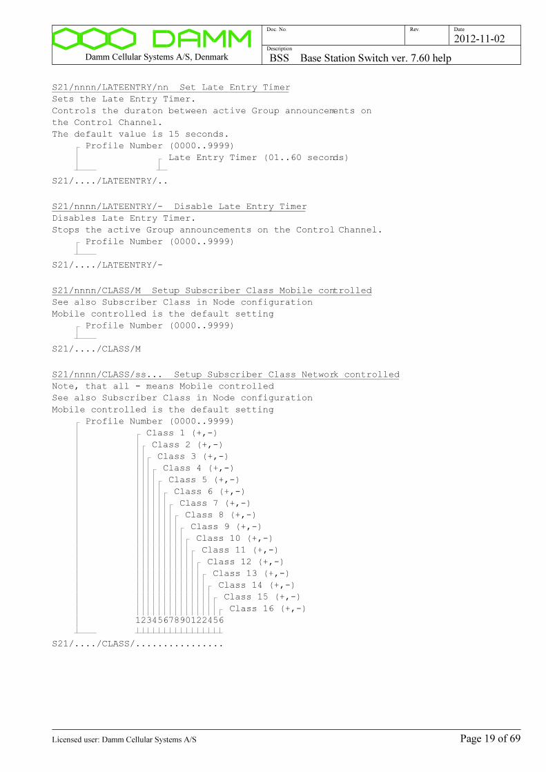
Damm Cellular Systems A/S, Denmark BSS Base Station Switch ver. 7.60 help
Doc. No. Rev. Date
Description
2012-11-02
S21/nnnn/LATEENTRY/nn Set Late Entry Timer
Sets the Late Entry Timer.
Controls the duraton between active Group announcements on
the Control Channel.
The default value is 15 seconds.
Profile Number (0000..9999)
Late Entry Timer (01..60 seconds)
S21/..../LATEENTRY/..
S21/nnnn/LATEENTRY/- Disable Late Entry Timer
Disables Late Entry Timer.
Stops the active Group announcements on the Control Channel.
Profile Number (0000..9999)
S21/..../LATEENTRY/-
S21/nnnn/CLASS/M Setup Subscriber Class Mobile controlled
See also Subscriber Class in Node configuration
Mobile controlled is the default setting
Profile Number (0000..9999)
S21/..../CLASS/M
S21/nnnn/CLASS/ss... Setup Subscriber Class Network controlled
Note, that all - means Mobile controlled
See also Subscriber Class in Node configuration
Mobile controlled is the default setting
Profile Number (0000..9999)
Class 1 (+,-)
Class 2 (+,-)
Class 3 (+,-)
Class 4 (+,-)
Class 5 (+,-)
Class 6 (+,-)
Class 7 (+,-)
Class 8 (+,-)
Class 9 (+,-)
Class 10 (+,-)
Class 11 (+,-)
Class 12 (+,-)
Class 13 (+,-)
Class 14 (+,-)
Class 15 (+,-)
Class 16 (+,-)
1234567890122456
S21/..../CLASS/................
Page 19 of 69Licensed user: Damm Cellular Systems A/S
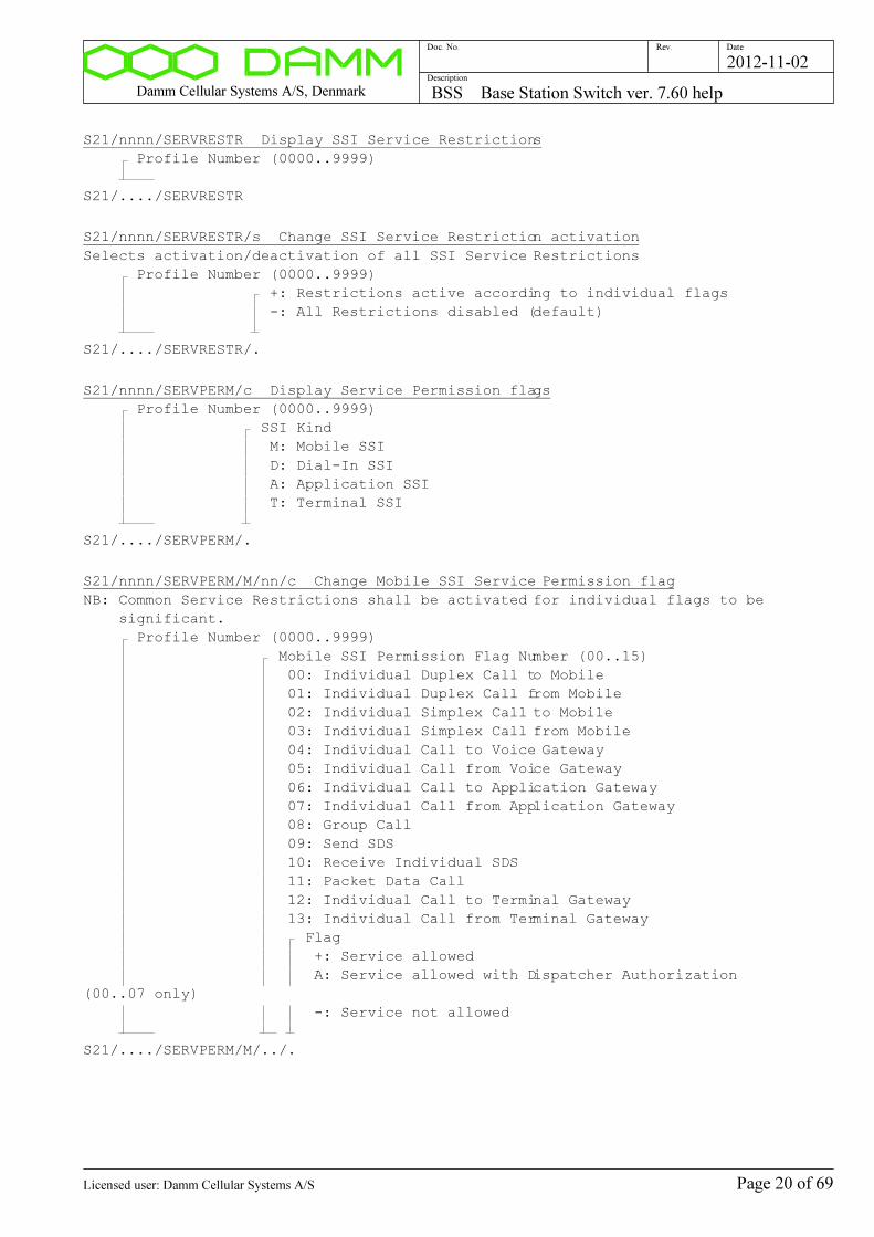
Damm Cellular Systems A/S, Denmark BSS Base Station Switch ver. 7.60 help
Doc. No. Rev. Date
Description
2012-11-02
S21/nnnn/SERVRESTR Display SSI Service Restrictions
Profile Number (0000..9999)
S21/..../SERVRESTR
S21/nnnn/SERVRESTR/s Change SSI Service Restriction activation
Selects activation/deactivation of all SSI Service Restrictions
Profile Number (0000..9999)
+: Restrictions active according to individual flags
-: All Restrictions disabled (default)
S21/..../SERVRESTR/.
S21/nnnn/SERVPERM/c Display Service Permission flags
Profile Number (0000..9999)
SSI Kind
M: Mobile SSI
D: Dial-In SSI
A: Application SSI
T: Terminal SSI
S21/..../SERVPERM/.
S21/nnnn/SERVPERM/M/nn/c Change Mobile SSI Service Permission flag
NB: Common Service Restrictions shall be activated for individual flags to be
significant.
Profile Number (0000..9999)
Mobile SSI Permission Flag Number (00..15)
00: Individual Duplex Call to Mobile
01: Individual Duplex Call from Mobile
02: Individual Simplex Call to Mobile
03: Individual Simplex Call from Mobile
04: Individual Call to Voice Gateway
05: Individual Call from Voice Gateway
06: Individual Call to Application Gateway
07: Individual Call from Application Gateway
08: Group Call
09: Send SDS
10: Receive Individual SDS
11: Packet Data Call
12: Individual Call to Terminal Gateway
13: Individual Call from Terminal Gateway
Flag
+: Service allowed
A: Service allowed with Dispatcher Authorization
(00..07 only)
-: Service not allowed
S21/..../SERVPERM/M/../.
Page 20 of 69Licensed user: Damm Cellular Systems A/S

Damm Cellular Systems A/S, Denmark BSS Base Station Switch ver. 7.60 help
Doc. No. Rev. Date
Description
2012-11-02
S21/nnnn/SERVPERM/D/nn/s Change Dial-In SSI Service Permission flag
NB: Common Service Restrictions shall be activated for individual flags to be
significant.
Profile Number (0000..9999)
Dial-In SSI Permission Flag Number (00..15)
06: Group Call
Flag
+: Service allowed
-: Service not allowed
S21/..../SERVPERM/D/../.
S21/nnnn/SERVPERM/A/nn/s Change Application SSI Service Permission flag
NB: Common Service Restrictions shall be activated for individual flags to be
significant.
Profile Number (0000..9999)
Application SSI Permission Flag Number (00..15)
00: Individual Call to Mobile
01: Individual Call from Mobile
02: Individual Call to Voice Gateway
03: Individual Call from Voice Gateway
04: Individual Call to Application Gateway
05: Individual Call from Application Gateway
06: Group Call
07: Send SDS
08: Receive Individual SDS
12: Individual Call to Terminal Gateway
13: Individual Call from Terminal Gateway
Flag
+: Service allowed
-: Service not allowed
S21/..../SERVPERM/A/../.
Page 21 of 69Licensed user: Damm Cellular Systems A/S

Damm Cellular Systems A/S, Denmark BSS Base Station Switch ver. 7.60 help
Doc. No. Rev. Date
Description
2012-11-02
S21/nnnn/SERVPERM/T/nn/s Change Terminal SSI Service Permission flag
NB: Common Service Restrictions shall be activated for individual flags to be
significant.
Profile Number (0000..9999)
Terminal SSI Permission Flag Number (00..15)
00: Individual Call to Mobile
01: Individual Call from Mobile
02: Individual Call to Voice Gateway
03: Individual Call from Voice Gateway
04: Individual Call to Application Gateway
05: Individual Call from Application Gateway
06: Group Call
07: Send SDS
08: Receive Individual SDS
12: Individual Call to Terminal Gateway
13: Individual Call from Terminal Gateway
Flag
+: Service allowed
-: Service not allowed
S21/..../SERVPERM/T/../.
S21/nnnn/SERVPERM/M/cc..c Change all Mobile SSI Service Permission flags
NB: Common Service Restrictions shall be activated for individual flags to be
significant.
Profile Number (0000..9999)
Mobile SSI Service Permission Flags:
+: Service allowed
A: Service allowed with Dispatcher Authorization (00..07
only)
-: Service not allowed
00: Individual Duplex Call to Mobile
01: Individual Duplex Call from Mobile
02: Individual Simplex Call to Mobile
03: Individual Simplex Call from Mobile
04: Individual Call to Voice Gateway
05: Individual Call from Voice Gateway
06: Individual Call to Application Gateway
07: Individual Call from Application Gateway
08: Group Call
09: Send SDS
10: Receive Individual SDS
11: Packet Data Call
12: Individual Call to Terminal Gateway
13: Individual Call from Terminal Gateway
14: (Spare)
15: (Spare)
S21/..../SERVPERM/M/................
Page 22 of 69Licensed user: Damm Cellular Systems A/S
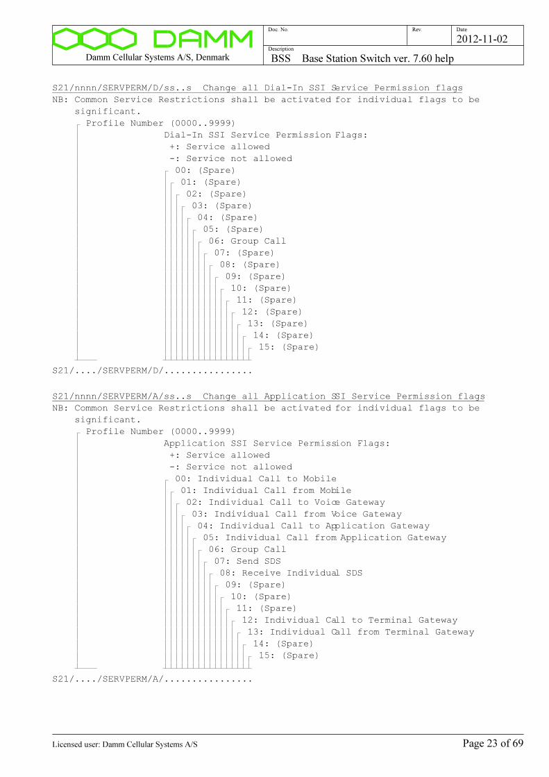
Damm Cellular Systems A/S, Denmark BSS Base Station Switch ver. 7.60 help
Doc. No. Rev. Date
Description
2012-11-02
S21/nnnn/SERVPERM/D/ss..s Change all Dial-In SSI Service Permission flags
NB: Common Service Restrictions shall be activated for individual flags to be
significant.
Profile Number (0000..9999)
Dial-In SSI Service Permission Flags:
+: Service allowed
-: Service not allowed
00: (Spare)
01: (Spare)
02: (Spare)
03: (Spare)
04: (Spare)
05: (Spare)
06: Group Call
07: (Spare)
08: (Spare)
09: (Spare)
10: (Spare)
11: (Spare)
12: (Spare)
13: (Spare)
14: (Spare)
15: (Spare)
S21/..../SERVPERM/D/................
S21/nnnn/SERVPERM/A/ss..s Change all Application SSI Service Permission flags
NB: Common Service Restrictions shall be activated for individual flags to be
significant.
Profile Number (0000..9999)
Application SSI Service Permission Flags:
+: Service allowed
-: Service not allowed
00: Individual Call to Mobile
01: Individual Call from Mobile
02: Individual Call to Voice Gateway
03: Individual Call from Voice Gateway
04: Individual Call to Application Gateway
05: Individual Call from Application Gateway
06: Group Call
07: Send SDS
08: Receive Individual SDS
09: (Spare)
10: (Spare)
11: (Spare)
12: Individual Call to Terminal Gateway
13: Individual Call from Terminal Gateway
14: (Spare)
15: (Spare)
S21/..../SERVPERM/A/................
Page 23 of 69Licensed user: Damm Cellular Systems A/S
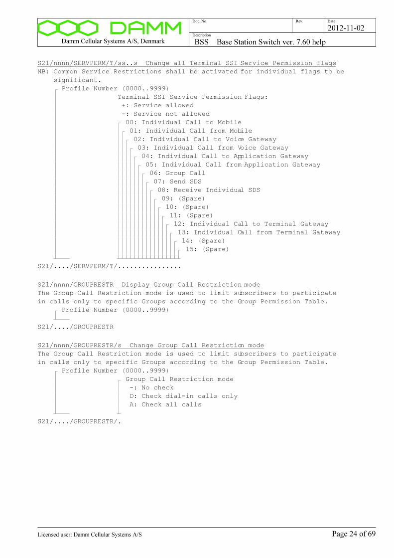
Damm Cellular Systems A/S, Denmark BSS Base Station Switch ver. 7.60 help
Doc. No. Rev. Date
Description
2012-11-02
S21/nnnn/SERVPERM/T/ss..s Change all Terminal SSI Service Permission flags
NB: Common Service Restrictions shall be activated for individual flags to be
significant.
Profile Number (0000..9999)
Terminal SSI Service Permission Flags:
+: Service allowed
-: Service not allowed
00: Individual Call to Mobile
01: Individual Call from Mobile
02: Individual Call to Voice Gateway
03: Individual Call from Voice Gateway
04: Individual Call to Application Gateway
05: Individual Call from Application Gateway
06: Group Call
07: Send SDS
08: Receive Individual SDS
09: (Spare)
10: (Spare)
11: (Spare)
12: Individual Call to Terminal Gateway
13: Individual Call from Terminal Gateway
14: (Spare)
15: (Spare)
S21/..../SERVPERM/T/................
S21/nnnn/GROUPRESTR Display Group Call Restriction mode
The Group Call Restriction mode is used to limit subscribers to participate
in calls only to specific Groups according to the Group Permission Table.
Profile Number (0000..9999)
S21/..../GROUPRESTR
S21/nnnn/GROUPRESTR/s Change Group Call Restriction mode
The Group Call Restriction mode is used to limit subscribers to participate
in calls only to specific Groups according to the Group Permission Table.
Profile Number (0000..9999)
Group Call Restriction mode
-: No check
D: Check dial-in calls only
A: Check all calls
S21/..../GROUPRESTR/.
Page 24 of 69Licensed user: Damm Cellular Systems A/S
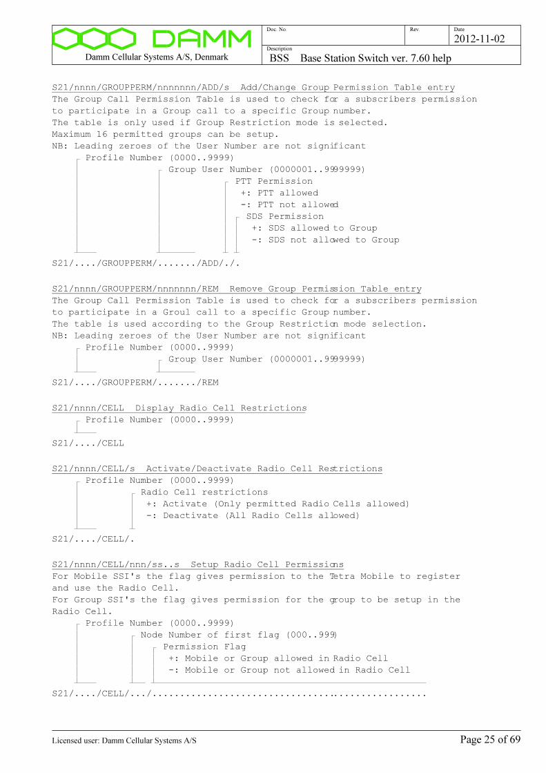
Damm Cellular Systems A/S, Denmark BSS Base Station Switch ver. 7.60 help
Doc. No. Rev. Date
Description
2012-11-02
S21/nnnn/GROUPPERM/nnnnnnn/ADD/s Add/Change Group Permission Table entry
The Group Call Permission Table is used to check for a subscribers permission
to participate in a Group call to a specific Group number.
The table is only used if Group Restriction mode is selected.
Maximum 16 permitted groups can be setup.
NB: Leading zeroes of the User Number are not significant
Profile Number (0000..9999)
Group User Number (0000001..9999999)
PTT Permission
+: PTT allowed
-: PTT not allowed
SDS Permission
+: SDS allowed to Group
-: SDS not allowed to Group
S21/..../GROUPPERM/......./ADD/./.
S21/nnnn/GROUPPERM/nnnnnnn/REM Remove Group Permission Table entry
The Group Call Permission Table is used to check for a subscribers permission
to participate in a Groul call to a specific Group number.
The table is used according to the Group Restriction mode selection.
NB: Leading zeroes of the User Number are not significant
Profile Number (0000..9999)
Group User Number (0000001..9999999)
S21/..../GROUPPERM/......./REM
S21/nnnn/CELL Display Radio Cell Restrictions
Profile Number (0000..9999)
S21/..../CELL
S21/nnnn/CELL/s Activate/Deactivate Radio Cell Restrictions
Profile Number (0000..9999)
Radio Cell restrictions
+: Activate (Only permitted Radio Cells allowed)
-: Deactivate (All Radio Cells allowed)
S21/..../CELL/.
S21/nnnn/CELL/nnn/ss..s Setup Radio Cell Permissions
For Mobile SSI's the flag gives permission to the Tetra Mobile to register
and use the Radio Cell.
For Group SSI's the flag gives permission for the group to be setup in the
Radio Cell.
Profile Number (0000..9999)
Node Number of first flag (000..999)
Permission Flag
+: Mobile or Group allowed in Radio Cell
-: Mobile or Group not allowed in Radio Cell
S21/..../CELL/.../..................................................
Page 25 of 69Licensed user: Damm Cellular Systems A/S

Damm Cellular Systems A/S, Denmark BSS Base Station Switch ver. 7.60 help
Doc. No. Rev. Date
Description
2012-11-02
S21/nnnn/VGNODE/n/nnn Setup Voice Gateway Node
Voice Gateway Nodes used of the Profile members.
Profile Number (0000..9999)
1: Primary Voice Gateway
2: Alternate Voice Gateway
Node Number (001..999, 000 for disabled)
S21/..../VGNODE/./...
S21/nnnn/PGNODE/n/nnn Setup Packet Data Gateway Node
Packet Date Gateway Nodes used of the Profile members.
Profile Number (0000..9999)
1: Primary Packet Data Gateway
2: Alternate Packet Data Gateway
Node Number (001..999, 000 for disabled)
S21/..../PGNODE/./...
S21/nnnn/POSUSERNO/n/nn..n Setup Position Destination User Number
Terminal Gateway sends Position Report to these Numbers
Profile Number (0000..9999)
1: Destination 1
2: Destination 2
User Number (1..9999999, blank or 0 for disabled)
S21/..../POSUSERNO/./.......
S21/nnnn/DNS/... Setup DNS Server IP Address
DNS Server IP Address given to the Mobile at DHCP Request
Profile Number (0000..9999)
IP Address (000..255 in each field)
S21/..../DNS/...............
S21/nnnn/DEL Delete Profile
Profile Number (0000..9999)
S21/..../DEL
Page 26 of 69Licensed user: Damm Cellular Systems A/S

Damm Cellular Systems A/S, Denmark BSS Base Station Switch ver. 7.60 help
Doc. No. Rev. Date
Description
2012-11-02
Subscriber Register SSI:
S22 Display SSI Register Status
S22
S22/nnnnnnnn Display SSI
SSI (00000001..16777215)
S22/........
S22/L/nnnnnnnn/snn/nn Display SSI list
First SSI (00000001..16777215)
Line Offset (-50..+50)
Number of Lines (01..45)
S22/L/......../.../..
S22/nnnnnnnn/REG Display SSI Registration
SSI (00000001..16777215)
S22/......../REG
S22/nnnnnnnn/REG/GROUP Display SSI Attached Groups
SSI (00000001..16777215)
S22/......../REG/GROUP
S22/TSI/... Display TSI
MCC (Mobile Country Code) (0001..1023)
MNC (Mobile Network Code) (0001..16383)
SSI (Short Subscriber Identity (0001..16777215)
S22/TSI/....:.....:........
S22/TSI/.../L Display TSI Chain List
NB: For debug only!
MCC (Mobile Country Code) (0001..1023)
MNC (Mobile Network Code) (0001..16383)
SSI (Short Subscriber Identity (0001..16777215)
S22/TSI/....:.....:......../L
S22/TSICHAIN/nnnnnn Display TSI Chain List
NB: For debug only!
SubIx (000000..nnnnnn)
S22/TSICHAIN/......
S22/TSIIXTB Display TSI Indax Table
NB: For debug only!
S22/TSIIXTB
Page 27 of 69Licensed user: Damm Cellular Systems A/S
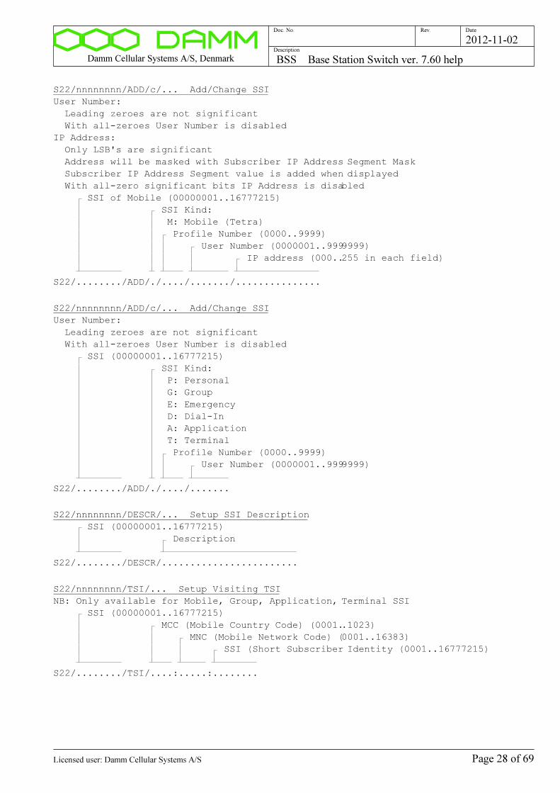
Damm Cellular Systems A/S, Denmark BSS Base Station Switch ver. 7.60 help
Doc. No. Rev. Date
Description
2012-11-02
S22/nnnnnnnn/ADD/c/... Add/Change SSI
User Number:
Leading zeroes are not significant
With all-zeroes User Number is disabled
IP Address:
Only LSB's are significant
Address will be masked with Subscriber IP Address Segment Mask
Subscriber IP Address Segment value is added when displayed
With all-zero significant bits IP Address is disabled
SSI of Mobile (00000001..16777215)
SSI Kind:
M: Mobile (Tetra)
Profile Number (0000..9999)
User Number (0000001..9999999)
IP address (000..255 in each field)
S22/......../ADD/./..../......./...............
S22/nnnnnnnn/ADD/c/... Add/Change SSI
User Number:
Leading zeroes are not significant
With all-zeroes User Number is disabled
SSI (00000001..16777215)
SSI Kind:
P: Personal
G: Group
E: Emergency
D: Dial-In
A: Application
T: Terminal
Profile Number (0000..9999)
User Number (0000001..9999999)
S22/......../ADD/./..../.......
S22/nnnnnnnn/DESCR/... Setup SSI Description
SSI (00000001..16777215)
Description
S22/......../DESCR/........................
S22/nnnnnnnn/TSI/... Setup Visiting TSI
NB: Only available for Mobile, Group, Application, Terminal SSI
SSI (00000001..16777215)
MCC (Mobile Country Code) (0001..1023)
MNC (Mobile Network Code) (0001..16383)
SSI (Short Subscriber Identity (0001..16777215)
S22/......../TSI/....:.....:........
Page 28 of 69Licensed user: Damm Cellular Systems A/S
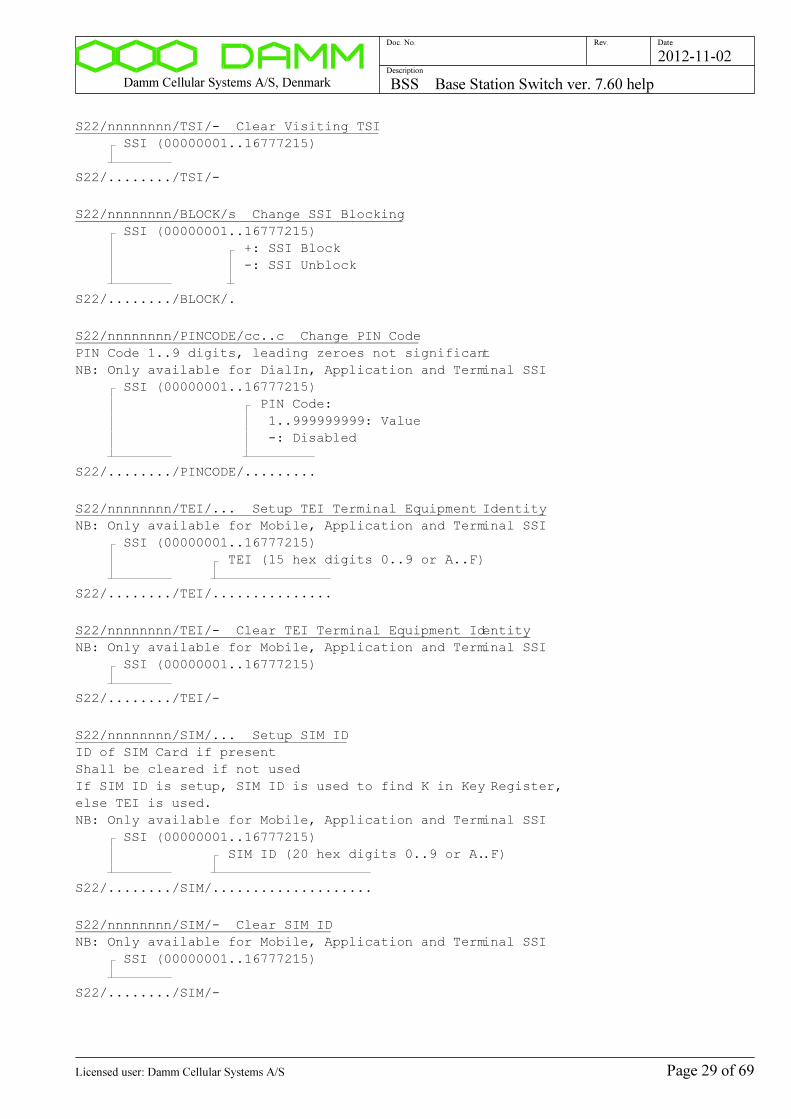
Damm Cellular Systems A/S, Denmark BSS Base Station Switch ver. 7.60 help
Doc. No. Rev. Date
Description
2012-11-02
S22/nnnnnnnn/TSI/- Clear Visiting TSI
SSI (00000001..16777215)
S22/......../TSI/-
S22/nnnnnnnn/BLOCK/s Change SSI Blocking
SSI (00000001..16777215)
+: SSI Block
-: SSI Unblock
S22/......../BLOCK/.
S22/nnnnnnnn/PINCODE/cc..c Change PIN Code
PIN Code 1..9 digits, leading zeroes not significant
NB: Only available for DialIn, Application and Terminal SSI
SSI (00000001..16777215)
PIN Code:
1..999999999: Value
-: Disabled
S22/......../PINCODE/.........
S22/nnnnnnnn/TEI/... Setup TEI Terminal Equipment Identity
NB: Only available for Mobile, Application and Terminal SSI
SSI (00000001..16777215)
TEI (15 hex digits 0..9 or A..F)
S22/......../TEI/...............
S22/nnnnnnnn/TEI/- Clear TEI Terminal Equipment Identity
NB: Only available for Mobile, Application and Terminal SSI
SSI (00000001..16777215)
S22/......../TEI/-
S22/nnnnnnnn/SIM/... Setup SIM ID
ID of SIM Card if present
Shall be cleared if not used
If SIM ID is setup, SIM ID is used to find K in Key Register,
else TEI is used.
NB: Only available for Mobile, Application and Terminal SSI
SSI (00000001..16777215)
SIM ID (20 hex digits 0..9 or A..F)
S22/......../SIM/....................
S22/nnnnnnnn/SIM/- Clear SIM ID
NB: Only available for Mobile, Application and Terminal SSI
SSI (00000001..16777215)
S22/......../SIM/-
Page 29 of 69Licensed user: Damm Cellular Systems A/S
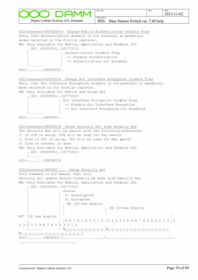
Damm Cellular Systems A/S, Denmark BSS Base Station Switch ver. 7.60 help
Doc. No. Rev. Date
Description
2012-11-02
S22/nnnnnnnn/AUTHDIS/s Change Mobile Authentication Disable Flag
Note, that Authentication disable is not possible in mandatory
modes selected in the Profile register.
NB: Only available for Mobile, Application and Terminal SSI
SSI (00000001..16777215)
Authentication Disable Flag
+: Disable Authentication
-: Authentication not disabled
S22/......../AUTHDIS/.
S22/nnnnnnnn/AIEDIS/s Change Air Interface Encryption Disable Flag
Note, that Air Interface Encryption disable is not possible in mandatory
mode selected in the Profile register.
NB: Only available for Mobile and Group SSI
SSI (00000001..16777215)
Air Interface Encryption Disable Flag
+: Disable Air Interface Encryption
-: Air Interface Encryption not disabled
S22/......../AIEDIS/.
S22/nnnnnnnn/SECSET/R Renew Security Set from Security Key
The Security Key will be search with the following references:
1) If SIM is setup, SIM will be used for Key search
2) Else if TEI is setup, TEI will be used for Key search
3) Else no renewal is done
NB: Only available for Mobile, Application and Terminal SSI
SSI (00000001..16777215)
S22/......../SECSET/R
S22/nnnnnnnn/SECSET/... Setup Security Set
This command is for manual test only
Security set update should normally be done from Security Key
NB: Only available for Mobile, Application and Terminal SSI
SSI (00000001..16777215)
Status
U: Unencrypted
E: Encrypted
RS (20 hex digits)
KS (32 hex digits)
KS' (32 hex digits)
9 8 7 6 5 4 3 2 1 0 5 4 3 2 1 0 9 8 7 6 5 4 3 2 1 0 5
4 3 2 1 0 9 8 7 6 5 4 3 2 1 0
ÿ ¿ ¿ ¿ ¿ ¿ ¿ ¿ ¿ ¿ ÿ ¿ ¿ ¿ ¿ ¿ ¿ ¿ ¿ ¿ ¿ ¿ ¿ ¿ ¿ ¿
ÿ ¿ ¿ ¿ ¿ ¿ ¿ ¿ ¿ ¿ ¿ ¿ ¿ ¿ ¿ ¿
S22/......../SECSET/./..................../................................/...
.............................
Page 30 of 69Licensed user: Damm Cellular Systems A/S

Damm Cellular Systems A/S, Denmark BSS Base Station Switch ver. 7.60 help
Doc. No. Rev. Date
Description
2012-11-02
S22/nnnnnnnn/SECSET/C Clear Security Set
NB: Only available for Mobile, Application and Terminal SSI
SSI (00000001..16777215)
S22/......../SECSET/C
S22/nnnnnnnn/GROUPTEXT/cc..c Setup Group Text Line
Group Text Line to show on the Terminal Screen
NB: Only available for Group SSI
SSI (00000001..16777215)
Group Text Line
S22/......../GROUPTEXT/...............
S22/nnnnnnnn/GROUPINCL Display Group Include Table
If the Group Include Table is enabled, a call to the group will also
include all Groups and Individuals in the Group Include Table.
NB: Only available for Group SSI
SSI (00000001..16777215)
S22/......../GROUPINCL
S22/nnnnnnnn/GROUPINCL/s Enable/Disable Group Include Table
If the Group Include Table is enabled, a call to the group will also
include all Groups and Individuals in the Group Include Table.
NB: Only available for Group SSI
SSI (00000001..16777215)
Group Table
+: Activate
-: Deactivate
S22/......../GROUPINCL/.
S22/nnnnnnnn/GROUPINCL/nnnnnnn/ADD Add/Change Group Include Table entry
If the Group Include Table is enabled, a call to the group will also
include all Groups and Individuals in the Group Include Table.
Note that leading zeroes of the User Number are not significant
NB: Only allowed for Group SSI
SSI (00000001..16777215)
User Number (0000001..9999999)
S22/......../GROUPINCL/......./ADD
S22/nnnnnnnn/GROUPINCL/nnnnnnn/REM Remove Group Include Table entry
If the Group Include Table is enabled, a call to the group will also
include all Groups and Individuals in the Group Include Table.
Note that leading zeroes of the User Number are not significant
NB: Only allowed for Group SSI
SSI (00000001..16777215)
User Number (0000001..9999999)
S22/......../GROUPINCL/......./REM
Page 31 of 69Licensed user: Damm Cellular Systems A/S
Damm Cellular Systems A/S, Denmark BSS Base Station Switch ver. 7.60 help
Doc. No. Rev. Date
Description
2012-11-02
S22/nnnnnnnn/CALLTRF/c Change Call Transfer
NB: Only available for Mobile, Application, DialIn and Terminal SSI
SSI (00000001..16777215)
Call Transfer Type
-: None
R: Not Reachable (Weak) (Not registered/no radio
contact)
A: No Answer (Medium) (Incl. Not Reachable)
B: Busy (Strong) (Incl. No Answer and Not
Reachable)
U: Unconditional (Always) (Excluding Blocked SSI)
N: Number Change (Always) (Including Blocked SSI)
S22/......../CALLTRF/.
S22/nnnnnnnn/CALLTRFNO/cc..c Change Call Transfer Number
NB: Only available for Mobile, Application, DialIn, Emergency and Terminal SSI
SSI (00000001..16777215)
Number (0..9,#,*,+,p or w)
S22/......../CALLTRFNO/..............................
S22/nnnnnnnn/CALLTRFTIME/nn Change Call Transfer delay time
Used to change the Alerting time before Call Transfer takes place
for "Call Transfer at no B-answer"
NB: Only available for Mobile, Application, DialIn and Terminal SSI
SSI (00000001..16777215)
Time in seconds (05..60, default 30)
S22/......../CALLTRFTIME/..
S22/nnnnnnnn/SUBREG/s Change Subscriber Register change permission
NB: Only available for Application SSI
SSI (00000001..16777215)
Subscriber Register changes from Application
+: Permitted
-: Not permitted
S22/......../SUBREG/.
S22/nnnnnnnn/DISCREETLIST/s Change Discreet Listening permission
Controls the permission for Discreet Listening from the Application.
NB: Only available for Application SSI
SSI (00000001..16777215)
Discreet Listening
+: Permitted
-: Not permitted
S22/......../DISCREETLIST/.
Page 32 of 69Licensed user: Damm Cellular Systems A/S
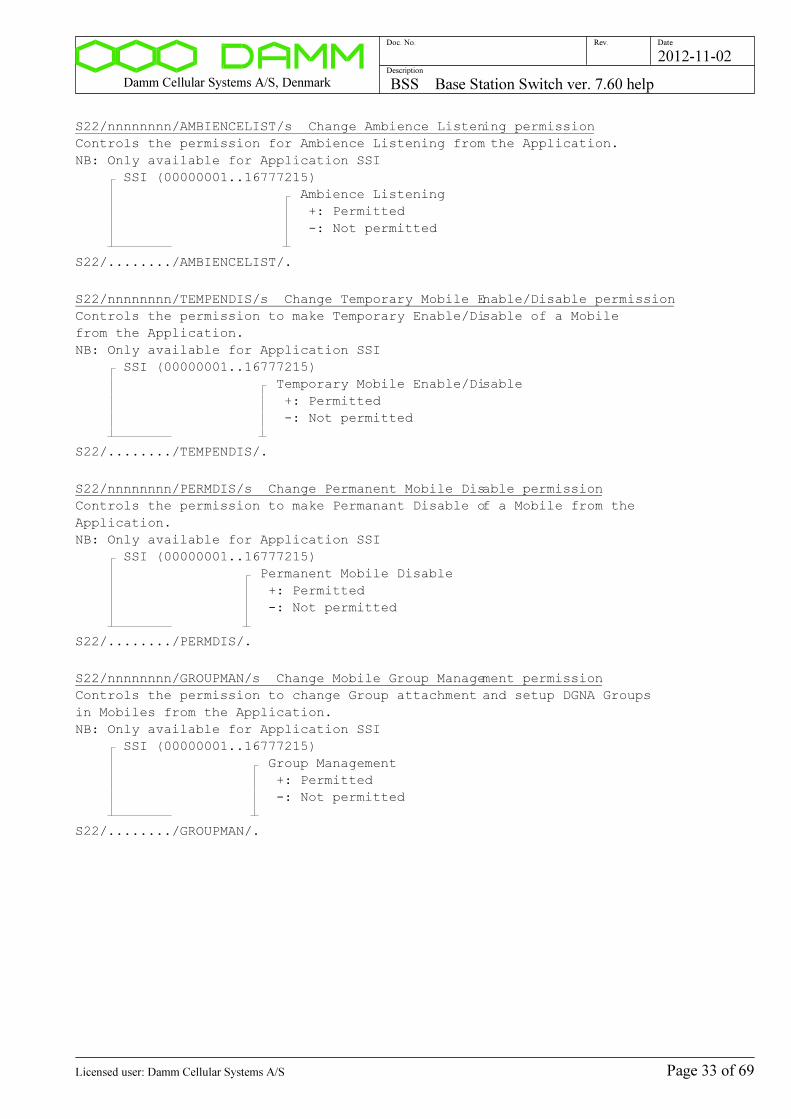
Damm Cellular Systems A/S, Denmark BSS Base Station Switch ver. 7.60 help
Doc. No. Rev. Date
Description
2012-11-02
S22/nnnnnnnn/AMBIENCELIST/s Change Ambience Listening permission
Controls the permission for Ambience Listening from the Application.
NB: Only available for Application SSI
SSI (00000001..16777215)
Ambience Listening
+: Permitted
-: Not permitted
S22/......../AMBIENCELIST/.
S22/nnnnnnnn/TEMPENDIS/s Change Temporary Mobile Enable/Disable permission
Controls the permission to make Temporary Enable/Disable of a Mobile
from the Application.
NB: Only available for Application SSI
SSI (00000001..16777215)
Temporary Mobile Enable/Disable
+: Permitted
-: Not permitted
S22/......../TEMPENDIS/.
S22/nnnnnnnn/PERMDIS/s Change Permanent Mobile Disable permission
Controls the permission to make Permanant Disable of a Mobile from the
Application.
NB: Only available for Application SSI
SSI (00000001..16777215)
Permanent Mobile Disable
+: Permitted
-: Not permitted
S22/......../PERMDIS/.
S22/nnnnnnnn/GROUPMAN/s Change Mobile Group Management permission
Controls the permission to change Group attachment and setup DGNA Groups
in Mobiles from the Application.
NB: Only available for Application SSI
SSI (00000001..16777215)
Group Management
+: Permitted
-: Not permitted
S22/......../GROUPMAN/.
Page 33 of 69Licensed user: Damm Cellular Systems A/S

Damm Cellular Systems A/S, Denmark BSS Base Station Switch ver. 7.60 help
Doc. No. Rev. Date
Description
2012-11-02
S22/nnnnnnnn/NUMBERMOD/s Change Number Modification Permission
Gives permission for the Gateway to present an external provided
number instead of the SSI's User Number.
Shall be set if the SSI is e.g. a Group Bridge or similar.
NB: Only available for Application and Terminal SSI
SSI (00000001..16777215)
Number Modification Permission
+: Number Modification allowed
-: Number Modification not allowed
S22/......../NUMBERMOD/.
S22/nnnnnnnn/EMERGPRI/nn Change Emergency Number Call Priority
Sets the Call Priority of an Emergency SSI
This will overrule Call Priority request 1..14 from mobiles
Emergency Priority 15 and 16 from mobiles will always be passed unchanged
Call Priority 15 (Emergency Call Priority) is recommended for Emergency Numbers
NB: Only available for Emergency SSI
SSI (00000001..16777215)
Call Priority
00 : Mobile Controlled
01..05: Low Priority (PTT Priority=0)
06..11: High Priority (PTT Priority=1)
12..14: Pre-emptive Priority (PTT Priority=2)
15 : Emergency Call Priority
S22/......../EMERGPRI/..
S22/nnnnnnnn/TARGET Display Target Table
NB: Command only available for Personal SSI
SSI (00000001..16777215)
S22/......../TARGET
S22/nnnnnnnn/TARGET/c Display Targets
Displays sorted according to Preference
NB: Command only available for Personal SSI
SSI (00000001..16777215)
Target Kind
V: Voice Call targets
S: SDS Call targets
I: IP Call targets
S22/......../TARGET/.
Page 34 of 69Licensed user: Damm Cellular Systems A/S
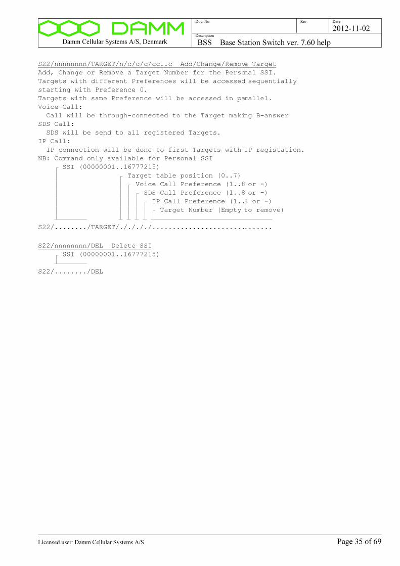
Damm Cellular Systems A/S, Denmark BSS Base Station Switch ver. 7.60 help
Doc. No. Rev. Date
Description
2012-11-02
S22/nnnnnnnn/TARGET/n/c/c/c/cc..c Add/Change/Remove Target
Add, Change or Remove a Target Number for the Personal SSI.
Targets with different Preferences will be accessed sequentially
starting with Preference 0.
Targets with same Preference will be accessed in parallel.
Voice Call:
Call will be through-connected to the Target making B-answer
SDS Call:
SDS will be send to all registered Targets.
IP Call:
IP connection will be done to first Targets with IP registation.
NB: Command only available for Personal SSI
SSI (00000001..16777215)
Target table position (0..7)
Voice Call Preference (1..8 or -)
SDS Call Preference (1..8 or -)
IP Call Preference (1..8 or -)
Target Number (Empty to remove)
S22/......../TARGET/././././..............................
S22/nnnnnnnn/DEL Delete SSI
SSI (00000001..16777215)
S22/......../DEL
Page 35 of 69Licensed user: Damm Cellular Systems A/S
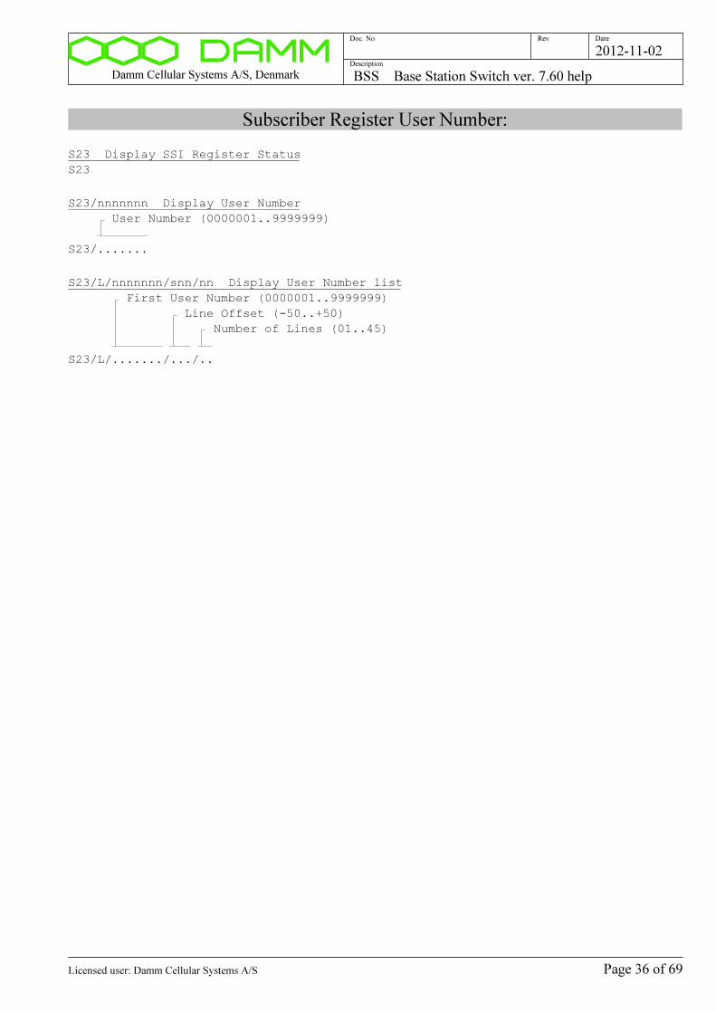
Damm Cellular Systems A/S, Denmark BSS Base Station Switch ver. 7.60 help
Doc. No. Rev. Date
Description
2012-11-02
Subscriber Register User Number:
S23 Display SSI Register Status
S23
S23/nnnnnnn Display User Number
User Number (0000001..9999999)
S23/.......
S23/L/nnnnnnn/snn/nn Display User Number list
First User Number (0000001..9999999)
Line Offset (-50..+50)
Number of Lines (01..45)
S23/L/......./.../..
Page 36 of 69Licensed user: Damm Cellular Systems A/S
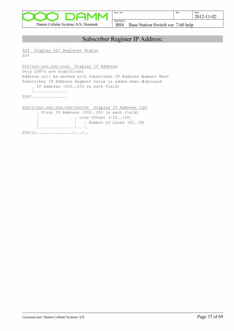
Damm Cellular Systems A/S, Denmark BSS Base Station Switch ver. 7.60 help
Doc. No. Rev. Date
Description
2012-11-02
Subscriber Register IP Address:
S24 Display SSI Register Status
S24
S24/nnn.nnn.nnn.nnnn Display IP Address
Only LSB's are significant
Address will be masked with Subscriber IP Address Segment Mask
Subscriber IP Address Segment value is added when displayed
IP Address (000..255 in each field)
S24/...............
S24/L/nnn.nnn.nnn.nnn/snn/nn Display IP Address list
First IP Address (000..255 in each field)
Line Offset (-50..+50)
Number of Lines (01..45)
S24/L/.............../.../..
Page 37 of 69Licensed user: Damm Cellular Systems A/S
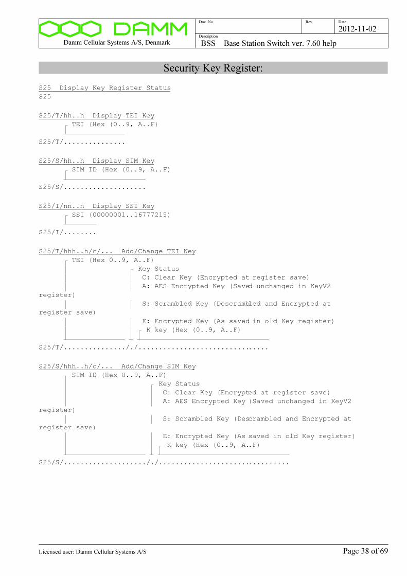
Damm Cellular Systems A/S, Denmark BSS Base Station Switch ver. 7.60 help
Doc. No. Rev. Date
Description
2012-11-02
Security Key Register:
S25 Display Key Register Status
S25
S25/T/hh..h Display TEI Key
TEI (Hex (0..9, A..F)
S25/T/...............
S25/S/hh..h Display SIM Key
SIM ID (Hex (0..9, A..F)
S25/S/....................
S25/I/nn..n Display SSI Key
SSI (00000001..16777215)
S25/I/........
S25/T/hhh..h/c/... Add/Change TEI Key
TEI (Hex 0..9, A..F)
Key Status
C: Clear Key (Encrypted at register save)
A: AES Encrypted Key (Saved unchanged in KeyV2
register)
S: Scrambled Key (Descrambled and Encrypted at
register save)
E: Encrypted Key (As saved in old Key register)
K key (Hex (0..9, A..F)
S25/T/..............././................................
S25/S/hhh..h/c/... Add/Change SIM Key
SIM ID (Hex 0..9, A..F)
Key Status
C: Clear Key (Encrypted at register save)
A: AES Encrypted Key (Saved unchanged in KeyV2
register)
S: Scrambled Key (Descrambled and Encrypted at
register save)
E: Encrypted Key (As saved in old Key register)
K key (Hex (0..9, A..F)
S25/S/...................././................................
Page 38 of 69Licensed user: Damm Cellular Systems A/S
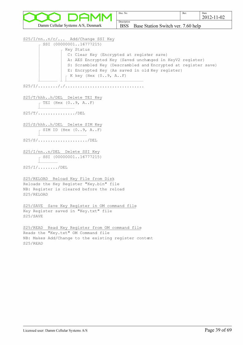
Damm Cellular Systems A/S, Denmark BSS Base Station Switch ver. 7.60 help
Doc. No. Rev. Date
Description
2012-11-02
S25/I/nn..n/c/... Add/Change SSI Key
SSI (00000001..16777215)
Key Status
C: Clear Key (Encrypted at register save)
A: AES Encrypted Key (Saved unchanged in KeyV2 register)
S: Scrambled Key (Descrambled and Encrypted at register save)
E: Encrypted Key (As saved in old Key register)
K key (Hex (0..9, A..F)
S25/I/.......././................................
S25/T/hhh..h/DEL Delete TEI Key
TEI (Hex (0..9, A..F)
S25/T/.............../DEL
S25/S/hhh..h/DEL Delete SIM Key
SIM ID (Hex (0..9, A..F)
S25/S/..................../DEL
S25/I/nn..n/DEL Delete SSI Key
SSI (00000001..16777215)
S25/I/......../DEL
S25/RELOAD Reload Key File from Disk
Reloads the Key Register "Key.bin" file
NB: Register is cleared before the reload
S25/RELOAD
S25/SAVE Save Key Register in OM command file
Key Register saved in "Key.txt" file
S25/SAVE
S25/READ Read Key Register from OM command file
Reads the "Key.txt" OM Command file
NB: Makes Add/Change to the existing register content
S25/READ
Page 39 of 69Licensed user: Damm Cellular Systems A/S
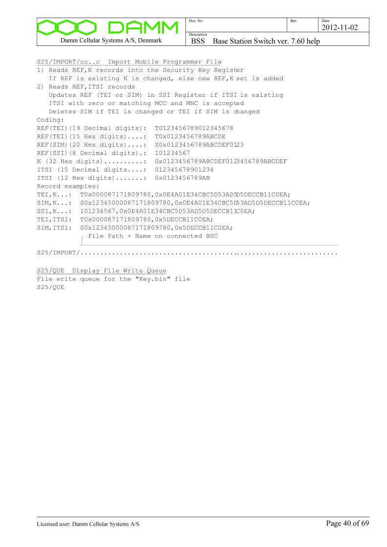
Damm Cellular Systems A/S, Denmark BSS Base Station Switch ver. 7.60 help
Doc. No. Rev. Date
Description
2012-11-02
S25/IMPORT/cc..c Import Mobile Programmer File
1) Reads REF,K records into the Security Key Register
If REF is existing K is changed, else new REF,K set is added
2) Reads REF,ITSI records
Updates REF (TEI or SIM) in SSI Register if ITSI is existing
ITSI with zero or matching MCC and MNC is accepted
Deletes SIM if TEI is changed or TEI if SIM is changed
Coding:
REF(TEI)(19 Decimal digits): T0123456789012345678
REF(TEI)(15 Hex digits)....: T0x0123456789ABCDE
REF(SIM)(20 Hex digits)....: S0x0123456789ABCDEF0123
REF(SSI)(8 Decimal digits).: I01234567
K (32 Hex digits)..........: 0x0123456789ABCDEF0123456789ABCDEF
ITSI (15 Decimal digits....: 012345678901234
ITSI (12 Hex digits).......: 0x0123456789AB
Record examples:
TEI,K...: T0x000087171809780,0x0E4A01E34CBC5D53AD5D5DECCB11C0EA;
SIM,K...: S0x12345000087171809780,0x0E4A01E34CBC5D53AD5D5DECCB11C0EA;
SSI,K...: I01234567,0x0E4A01E34CBC5D53AD5D5DECCB11C0EA;
TEI,ITSI: T0x000087171809780,0x5DECCB11C0EA;
SIM,ITSI: S0x12345000087171809780,0x5DECCB11C0EA;
File Path + Name on connected BSC
S25/IMPORT/..................................................................
S25/QUE Display File Write Queue
File write queue for the "Key.bin" file
S25/QUE
Page 40 of 69Licensed user: Damm Cellular Systems A/S

Damm Cellular Systems A/S, Denmark BSS Base Station Switch ver. 7.60 help
Doc. No. Rev. Date
Description
2012-11-02
Organization Register:
S26 Display Organization Register Status
S26
S26/nnn Display Organization
Organization Number (000..999)
S26/...
S26/L/nnn/snn/nn Display Organization list
Organization Number (000..999)
Line Offset (-50..+50)
Number of Lines (01..50)
S26/L/.../.../..
S26/nnn/ADD/cc..c Add/Change Organization
NB: All ranges automatically set to full range for Organization 000
Organization Number (000..999)
Description
S26/.../ADD/........................
S26/nnn/PROFNO/... Change Profile Number range
Limits the Profile Numbers, which can be added via an Application Gateway
NB: Automatically set to full range for Organization 000
Organization Number (000..999)
Lowest permitted Profile Number (0000..9999)
Highest permitted Profile Number (0000..9999) (0=Barred)
S26/.../PROFNO/..../....
S26/nnn/SSI/... Change SSI range
Limits the SSIs, which can be added via an Application Gateway
NB: Automatically set to full range for Organization 000
Organization Number (000..999)
Lowest permitted SSI (00000001..16777215)
Highest permitted SSI (00000001..16777215) (0=Barred)
S26/.../SSI/......../........
Page 41 of 69Licensed user: Damm Cellular Systems A/S
Damm Cellular Systems A/S, Denmark BSS Base Station Switch ver. 7.60 help
Doc. No. Rev. Date
Description
2012-11-02
S26/nnn/USERNO/... Change User Number range
Limits the User Numbers, which can be added via an Application Gateway
Leading zeroes in User Numbers are not significant
NB: Automatically set to full range for Organization 000
Organization Number (000..999)
Lowest permitted User Number (0000001..9999999)
Highest permitted User Number (0000001..9999999)
(0=Barred)
S26/.../USERNO/......./.......
S26/nnn/IPADDR/... Change IP Address range
Limits the IP Addresses, which can be added via an Application Gateway
Subscriber IP Address Segment value is added when displayed
NB: Automatically set to full range for Organization 000
Organization Number (000..999)
Lowest permitted IP Address (000..255)
Highest permitted IP Address (000..255)
(0=Barred)
S26/.../IPADDR/.............../...............
S26/nnn/PUBLRESTR/s Change Publish Restriction flag
Restricts the publishing of the Organisation.
Setting this flag will hide the existence of the Organization for all except
Home Organization Applications.
Organization Number (000..999)
Publish Restriction flag
+: Publish to Home Organization Applications only
-: Publish to all Applications
S26/.../PUBLRESTR/.
S26/nnn/NODERESTR/s Change Node Status Restriction flag
Restricts the publishing of Node Status.
Setting this flag will hide the Node Status in Applications.
Organization Number (000..999)
Node Status Restriction flag
+: Node Status NOT sent to Applications
-: Node Status sent to Applications
S26/.../NODERESTR/.
S26/nnn/DEL Delete Organization
Organization Number (000..999)
S26/.../DEL
Page 42 of 69Licensed user: Damm Cellular Systems A/S
Damm Cellular Systems A/S, Denmark BSS Base Station Switch ver. 7.60 help
Doc. No. Rev. Date
Description
2012-11-02
Audio Messages
S30 AUDIO MESSAGES
S30 Display Audio Message status
The Audio Messages are Voice and Tone sequences used in the system as
Audio announcements.
They are read-in from .wav files located in the Audio directory.
Format shall be CCITT A-Law 8kHz 8-bit mono.
English versions are delivered from the factory as standard
Messages in different languages and with adjusted content can be
recorded with the Windows "Sound Recorder" tool.
When loaded from the files, versions coded as Tetra Voice are also
generated automatically.
S30
S30/R Reload Audio Messages from disk
Reads all .wav files in the Audio directory.
Tetra Audio versions are also generated automatically.
S30/R
Command description:
Page 43 of 69Licensed user: Damm Cellular Systems A/S
Damm Cellular Systems A/S, Denmark BSS Base Station Switch ver. 7.60 help
Doc. No. Rev. Date
Description
2012-11-02
TetraFlex Shares
S31 TETRAFLEX SHARES
S31 Display TetraFlex Shares
Displays the list of Version Dates in the TetraFlex share.
Automatically updated every 30 second.
S31
S31/nn Display TetraFlex Share
Share Number (00..nn)
S31/..
S31/nn/nnnn-nn-nn Change Version Date
Changes all File Dates to the selected value
Used to set the Version Date to the correct one, if the has been
accidentially modified.
Time is set to 12:00:00 UTC
Share Number (00..nn)
File Date (e.g. 2012-06-27)
S31/../....-..-..
Command description:
Page 44 of 69Licensed user: Damm Cellular Systems A/S
Damm Cellular Systems A/S, Denmark BSS Base Station Switch ver. 7.60 help
Doc. No. Rev. Date
Description
2012-11-02
InterNode OM Command
S50 INTERNODE OM COMMAND
S50 Display Command function
S50
S50/D Display last received OM Command/Response
S50/D
S50/ccc/cc..c Send OM Command to other Node(s)
See OM Help for available commands
Multicommands separated with the '|' character is supported.
As '|' however can not been send as it will be interpreted of the OM Program,
the character '^' shall be used instead. The OM S50 command interpreter will
modify
'^' to '|' before it is send.
Node number (ALL or 001..999)
OM Command String
S50/.../......................................................................
Command description:
Page 45 of 69Licensed user: Damm Cellular Systems A/S
Damm Cellular Systems A/S, Denmark BSS Base Station Switch ver. 7.60 help
Doc. No. Rev. Date
Description
2012-11-02
Application Gateway Subscriber Register Command
S51 API SUBSCRIBER REGISTER COMMAND
S51 Display Command function
S51
S51/D Display last API Command/Response
S51/D
S51/nnnnnnnn/cc..c Execute API Command
The command simulates commands from the ApiDll to modify the Subscriber
Register.
Commands shall be entered in the ApiDll format ("21/..., 22/... and 26/...).
The Gateway will make syntax and permission check on the command, modify
it to the BSC format (S21/..., S22/... and S26/...) and send it to the
Master Subscriber Register Node.
See ApiDll Help for command syntax.
See also 20/QUE, 51/D and 51/... commands for the ApiDll.
See also S51/D for the Gateway Node.
See also S50/D and S20/QUE commands for the Master Subscriber Register Node.
SSI of of Application DLL (00000001..16777215)
Command String
S51/......../.................................................................
Command description:
Page 46 of 69Licensed user: Damm Cellular Systems A/S
Damm Cellular Systems A/S, Denmark BSS Base Station Switch ver. 7.60 help
Doc. No. Rev. Date
Description
2012-11-02
Log Server Message test queue:
S64 LOG SERVER MESSAGE TEST QUEUE
S64 Display Log Server Connection Status
S64
S64/N Display next Log Server message
S64/N
S64/N+ Display next Log Server message extended
S64/N+
S64/S Set Log Server message test queue to start
S64/S
S64/C Clear Log Server message test queue
S64/C
S64/s Log Server Message suppression
+: Display all Log Server messages
-: Suppress some Log Server messages (default)
S64/.
S64/hh/hh..hh Send message to Home Log Servers
Message ID (hex)
Optional Parameters (hex)
02 04 06 08 10 12 14 16 18 20 22 24 26 28 30 32
ÿ ¿ ¿ ¿ ¿ ¿ ¿ ¿ ¿ ¿ ¿ ¿ ¿ ¿ ¿ ¿ ¿ ¿ ¿ ¿ ¿ ¿ ¿ ¿ ¿ ¿ ¿ ¿ ¿ ¿ ¿ ¿ ¿
S64/../..................................................................
S64/nnn.nnn.nnn.nnn/hh/hh..hh Send message to Log Servers
IP multicast address (000..255 in each field)
Message ID (hex)
Optional Parameters (hex)
02 04 06 08 10 12 14 16 18 20 22 24 26
28 30 32
ÿ ¿ ¿ ¿ ¿ ¿ ¿ ¿ ¿ ¿ ¿ ¿ ¿ ¿ ¿ ¿ ¿ ¿ ¿ ¿ ¿ ¿ ¿ ¿ ¿ ¿ ¿ ¿ ¿ ¿ ¿ ¿ ¿
S64/.............../../........................................................
..........
Command description:
Page 47 of 69Licensed user: Damm Cellular Systems A/S
Damm Cellular Systems A/S, Denmark BSS Base Station Switch ver. 7.60 help
Doc. No. Rev. Date
Description
2012-11-02
Internode Control Message test queue:
S65 INTERNODE CONTROL MESSAGE TEST QUEUE
S65 Display Internode Connection status
S65
S65/N Display next Internode Control Message
S65/N
S65/N+ Display next Internode Control Message extended
S65/N+
S65/S Set Internode Control Message test queue to start
S65/S
S65/C Clear Internode Control Message test queue
S65/C
S65/s Internode Control Message suppression
+: Display all Internode Control messages
-: Suppress some Internode Control messages (default)
S65/.
S65/ALL/hh/hh..hh Send Control Message to all Nodes
Message ID (hex)
Optional Parameters (hex)
02 04 06 08 10 12 14 16 18 20 22 24 26 28 30 32
ÿ ¿ ¿ ¿ ¿ ¿ ¿ ¿ ¿ ¿ ¿ ¿ ¿ ¿ ¿ ¿ ¿ ¿ ¿ ¿ ¿ ¿ ¿ ¿ ¿ ¿ ¿ ¿ ¿ ¿ ¿ ¿ ¿
S65/ALL/../..................................................................
S65/SD/hh/hh..hh Send Control Message to Subscriber Register Download Nodes
Message ID (hex)
Optional Parameters (hex)
02 04 06 08 10 12 14 16 18 20 22 24 26 28 30 32
ÿ ¿ ¿ ¿ ¿ ¿ ¿ ¿ ¿ ¿ ¿ ¿ ¿ ¿ ¿ ¿ ¿ ¿ ¿ ¿ ¿ ¿ ¿ ¿ ¿ ¿ ¿ ¿ ¿ ¿ ¿ ¿ ¿
S65/SD/../..................................................................
S65/DL/hh/hh..hh Send Control Message to Discreet Listening Nodes
Message ID (hex)
Optional Parameters (hex)
02 04 06 08 10 12 14 16 18 20 22 24 26 28 30 32
ÿ ¿ ¿ ¿ ¿ ¿ ¿ ¿ ¿ ¿ ¿ ¿ ¿ ¿ ¿ ¿ ¿ ¿ ¿ ¿ ¿ ¿ ¿ ¿ ¿ ¿ ¿ ¿ ¿ ¿ ¿ ¿ ¿
S65/DL/../..................................................................
Page 48 of 69Licensed user: Damm Cellular Systems A/S

Damm Cellular Systems A/S, Denmark BSS Base Station Switch ver. 7.60 help
Doc. No. Rev. Date
Description
2012-11-02
S65/nnn/hh/hh..hh Send Control Message to specific Node
Node Number (001..NodeMax)
Message ID (hex)
Optional Parameters (hex)
02 04 06 08 10 12 14 16 18 20 22 24 26 28 30 32
ÿ ¿ ¿ ¿ ¿ ¿ ¿ ¿ ¿ ¿ ¿ ¿ ¿ ¿ ¿ ¿ ¿ ¿ ¿ ¿ ¿ ¿ ¿ ¿ ¿ ¿ ¿ ¿ ¿ ¿ ¿ ¿ ¿
S65/.../../..................................................................
S65/nnn.nnn.nnn.nnn/hh/hh..hh Send Control Message to specific IP Address
IP address (000..255 in each field)
Message ID (hex)
Optional Parameters (hex)
02 04 06 08 10 12 14 16 18 20 22 24 26
ÿ ¿ ¿ ¿ ¿ ¿ ¿ ¿ ¿ ¿ ¿ ¿ ¿ ¿ ¿ ¿ ¿ ¿ ¿ ¿ ¿ ¿ ¿ ¿ ¿ ¿ ¿
S65/.............../../......................................................
Command description:
Page 49 of 69Licensed user: Damm Cellular Systems A/S

Damm Cellular Systems A/S, Denmark BSS Base Station Switch ver. 7.60 help
Doc. No. Rev. Date
Description
2012-11-02
BSS Configuration Commands:
S70 Display last file save result
S70
S70/SAVE Save BSS Configuration
Note that BSS Configuration changes are saved automatically
S70/SAVE
Page 50 of 69Licensed user: Damm Cellular Systems A/S
Damm Cellular Systems A/S, Denmark BSS Base Station Switch ver. 7.60 help
Doc. No. Rev. Date
Description
2012-11-02
General Node configuration:
S71 Display General Node configuration
S71
S71/NODENO/nnn Change Node Number
Max. node number is limited of:
a) Compile constant, see S00/C command
b) License Dongle, see S04 command
Node Number (001..nnn)
S71/NODENO/...
S71/IP/MCADDR/... Change Multicast Base IP Address
Defines the start address for the Multicast Address block
The entered address is truncated with a /28 mask
Used addresses (for default Base Address):
224.239.016.001: Main Internode Control Multicast Address
224.239.016.003: Discreet Listening Multicast Address
224.239.016.004: Subscriber Register Download Multicast Address
Default Base Address: 224.239.016.000
IP address (224.000.002.000..239.255.255.254)
S71/IP/MCADDR/...............
S71/IP/MCPORT/nnnnn Change Control Multicast Port Number
UDP Port Number for Multicast communication with other Nodes
Default Port Number is 42400
Multicast UDP Port (00000..65535)
S71/IP/MCPORT/.....
S71/IP/UCPORT/nnnnn Change Control Unicast Port Number
UDP Port Number for Unicast communication with other Nodes
Default Port Number is 42401
Unicast UDP Port (00000..65535)
S71/IP/UCPORT/.....
S71/IP/LOGADDR/... Change Log Multicast IP Address
IP Multicast Address for the Serving Log Servers
If more than one Log Server Group is used, change the last field
to the actual Log Server Group Number
Default Address is 224.239.017.001
IP address (224.000.002.000..239.255.255.254)
S71/IP/LOGADDR/...............
Page 51 of 69Licensed user: Damm Cellular Systems A/S
Damm Cellular Systems A/S, Denmark BSS Base Station Switch ver. 7.60 help
Doc. No. Rev. Date
Description
2012-11-02
S71/IP/LOGPORT/nnnnn Change Log UDP Port Number
UDP Port Number for Log Servers
Default Port Number is 42402
UDP Port (00000..65535)
S71/IP/LOGPORT/.....
S71/IP/CMOIPADDR/... Change CMoIP Multicast IP Address
Most significant bytes of IP Multicast Address for CMoIP
Default Address is 225.000.x.x
CMoIP IP address (225.000..239.255)
S71/IP/CMOIPADDR/.......
S71/MCC/nnnn Change Mobile Country Code
MCC (0001..1023)
S71/MCC/....
S71/MNC/nnnnn Change Mobile Network Code
MNC (0001..16383)
S71/MNC/.....
S71/NODETIMEOUT/nnnn Change Inter-node Timeout
Changes the timeout of responses from other Nodes.
Shall be at least 200 msec. larger than the peak roud-trip time to any Node.
Use Ping.exe to determine the actual round-trip time.
Note, that the last digit will be truncated to zero.
The default value is 500 msec.
Inter-node Timeout (0200..2550 [msec])
S71/NODETIMEOUT/....
S71/MULTIVOCODER/s Change Multivocoder selection
Changes the function of the Vocoders for the Gateways
Disabled:
Core network uses always Tetra Coded Voice
Functionality as in TetraFlex before version 7.60
Enabled:
Core network uses several different Voice codings
Allows higher quality voice between Appl., Term. and Voice Gateways
Requirement:
1) Vocoders shall be present in BS/TR
2) Faster BS downlink IP connection (2048/512kbit/s for 4-carrier BS)
NB: This setting shall be the same on all Nodes in the system
Multivocoder
-: Disabled
+: Enabled
S71/MULTIVOCODER/.
Page 52 of 69Licensed user: Damm Cellular Systems A/S
Damm Cellular Systems A/S, Denmark BSS Base Station Switch ver. 7.60 help
Doc. No. Rev. Date
Description
2012-11-02
S71/VOICEBUF/n Change Voice Buffer length
Changes the initial length of the Voice Elastic Buffer
This value is used to select a resonable balance between delay and slips.
Lower value gives lower average speech delay but more slips.
Higher value gives less slips but higher average speech delay.
Default value is 2 Voice Frames (2x60msec.)
A higher value can improve voice quality if the transmission network has
high jitter and/or End-to-End Encryption is used.
Initial Voice Buffer Length (1..5, default=2)
S71/VOICEBUF/.
S71/SUBIPADDR/... Change Subscriber IP Address Segment
IP Address Segment used for Mobiles for Packet Data
NB: The LSB of the Address is automatically cleared by the Mask
Default Address is 172.28.0.0/16
IP Address
Mask (12..30)
S71/SUBIPADDR/.............../..
S71/SUBMODE/c Change Subscriber Register Mode
Controls replication between Nodes/BSC's
A BSC set to Master is automatically running Slave when Standby
The two redundant BSC's shall have same setting
For single node systems with redundant BSC's, both shall be set to Master
Warning: Do only select Master Mode on one Node!
Subscriber Register Mode
-: Single (No update to/from other BSC's)
M: Master (Active BSC : Sends updates to all slave BSC's)
(Standby BSC: Gets update from Master, no changes)
S: Slave (Gets update from Master, no OM/NM changes)
S71/SUBMODE/.
S71/KEYREG/s Key Register activation
Activates the Security Key Register function
NB: Shall only be activated on BSC's with Subscriber
Register in Single or Master mode
Key Register
+: Activation
-: Deactivation
S71/KEYREG/.
Page 53 of 69Licensed user: Damm Cellular Systems A/S

Damm Cellular Systems A/S, Denmark BSS Base Station Switch ver. 7.60 help
Doc. No. Rev. Date
Description
2012-11-02
S71/SHARENAME/cc..c Share Name
Sets the Share Name for the File Share for updates for ApiDll, Dispatcher,
Clients etc.
Shall match the Share Name used for "Share" directory.
For a single-node PC the default value is "TetraFlex".
For a Multi-node PC the share for each Node shall be setup to be different.
Share Name
S71/SHARENAME/................................
S71/SHAREUSER/cc..c Share User
Sets the Share User Name for the File Share.
The User shall have Read access to the Share.
The default value is "Tetra".
Share User
S71/SHAREUSER/................................
S71/SHAREPASSWORD/cc..c Share Password
Sets the Share Password for the File Share User.
The default value is "Tetra".
Share Password
S71/SHAREPASSWORD/................................
S71/TR Display TR Use
S71/TR
S71/TR/nn/s Change TR Use
Note, that S72/TR/.. and S77/TR/... commands can also change the
setting from Unused to Tetra respectively.
TR Address (11..48)
TR Use:
-: Unused
T: Tetra
S: Spare
S71/TR/../.
Page 54 of 69Licensed user: Damm Cellular Systems A/S
Damm Cellular Systems A/S, Denmark BSS Base Station Switch ver. 7.60 help
Doc. No. Rev. Date
Description
2012-11-02
Tetra Cell Configuration:
S72 Display Tetra Cell configuration
S72
S72/CNFG/+ Activate Tetra Cell
Only possible if allowed of License Dongle
S72/CNFG/+
S72/CNFG/- Deactivate Tetra Cell
S72/CNFG/-
S72/BSPWR/+nn.n Change Tetra BS Output Power
Command used set the Tetra BS Antenna Tetra carrier output power
at un-activated Power Reduction.
Available range:
BS421 : +27.0 to +40.0 dBm
TR412 : +26.0 to +40.0 dBm
TR412H: +30.0 to +44.0 dBm
If the value is lower or higher than the permitted range, the minimum
or maximum power respectively will be set.
NB: This setting controls the Antenna Power, when Power Reduction in not
activated.
Normal Tetra Antenna Power per carrier (+26.0 to +44.0dBm)
S72/BSPWR/+....
S72/BSPWR/- Set Tetra BS Output Power to TR Controlled
S72/BSPWR/-
S72/BSPWR/RED/+nn.n Change Tetra BS Reduced Output Power
Command used set the Tetra BS Antenna Tetra carrier output power
at activated Power Reduction.
Reduced Power Output mode is activated through an input on either SB421
or BS41x.
Available range:
BS421 : +27.0 to +40.0 dBm (0.5 to 10W Tetra)
TR412 : +26.0 to +40.0 dBm (0.4 to 10W Tetra)
TR412H: +30.0 to +44.0 dBm (1.0 to 25W Tetra)
If the value is lower or higher than the permitted range, the minimum
or maximum power respectively will be set.
Reduced Tetra Antenna Power per carrier (+26.0 to +44.0dBm)
S72/BSPWR/RED/+....
S72/BSPWR/RED/- Set Tetra BS Reduced Output Power to TR Controlled
S72/BSPWR/RED/-
S72/BSPWR/RED/N Set Tetra BS Reduced Output Power to Normal
S72/BSPWR/RED/N
Page 55 of 69Licensed user: Damm Cellular Systems A/S
Damm Cellular Systems A/S, Denmark BSS Base Station Switch ver. 7.60 help
Doc. No. Rev. Date
Description
2012-11-02
S72/SCCH/n Change number of SCCH to setup
Number of SCCH to setup (0..3)
S72/SCCH/.
S72/PDCH/nn Change minimum number of PDCH
Command used to reserve a number of timeslots exclusively for
Packet Data. These wil not be pre-empted for voice communication.
Default is 0.
Minimum number of PDCH (00..99)
S72/PDCH/..
S72/FALLBACK/s Change Fallback Mode Indication
Changes Fallback Mode indication to the mobiles
If activated, fallback mode will be indicated status update are not
received from other Nodes.
Fallback mode indicates to mobiles, that full network service are
not available.
Shall be disabled for single-site systems.
Fallback Mode Indication
+: Activate
-: Disable
S72/FALLBACK/.
S72/MSPWR/n Change max. MS TX Power
Max. MS TX Power Level (0..7)
0: Spare
1: +15dBm (30mW)
2: +20dBm (100mW)
3: +25dBm (300mW)
4: +30dBm (1W)
5: +35dBm (3W)
6: +40dBm (10W)
7: +45dBm (30W)
S72/MSPWR/.
Page 56 of 69Licensed user: Damm Cellular Systems A/S
Damm Cellular Systems A/S, Denmark BSS Base Station Switch ver. 7.60 help
Doc. No. Rev. Date
Description
2012-11-02
S72/MSACC/nn Change min. MS RX Access Level
Min. MS RX Access Level (0..17)
00: -125dBm
01: -120dBm
02: -115dBm
03: -110dBm
04: -105dBm
05: -100dBm
06: -95dBm
07: -90dBm
..:
15: -50dBm
S72/MSACC/..
S72/ACCPAR/nn Radio Access Parameter
Controls when the mobile starts to reduce its output power at high
received signal strength.
For a 1W mobile, output power will start to decrease at -67dBm input
signal strength with the default setting.
Radio Access Parameter
00: -53dBm
01: -51dBm
02: -49dBm
03: -47dBm
04: -45dBm
05: -43dBm
06: -41dBm
07: -39dBm
08: -37dBm (Default)
09: -35dBm
10: -33dBm
11: -31dBm
12: -29dBm
13: -27dBm
14: -25dBm
15: -23dBm
S72/ACCPAR/..
Page 57 of 69Licensed user: Damm Cellular Systems A/S

Damm Cellular Systems A/S, Denmark BSS Base Station Switch ver. 7.60 help
Doc. No. Rev. Date
Description
2012-11-02
S72/DLTO/nn Change Radio Downlink Timeout
Radio Downlink Timeout
00: Disabled
01: 144 timeslot
02: 288 timeslot
03: 432 timeslot
04: 576 timeslot
05: 720 timeslot
06: 864 timeslot
07: 1008 timeslot
08: 1152 timeslot (Default)
09: 1296 timeslot
10: 1440 timeslot
11: 1584 timeslot
12: 1728 timeslot
13: 1872 timeslot
14: 2016 timeslot
15: 2160 timeslot
S72/DLTO/..
S72/CONNTIMEOUT/n Change Connection Timeout
Controls the timeout Tetra Mobile LA Registration
LA Registration Timeout
0: Disabled
1: 10 min.
2: 30 min.
3: 1 hour
4: 2 hour
5: 4 hour
6: 8 hour
7: 24 hour
S72/CONNTIMEOUT/.
Page 58 of 69Licensed user: Damm Cellular Systems A/S
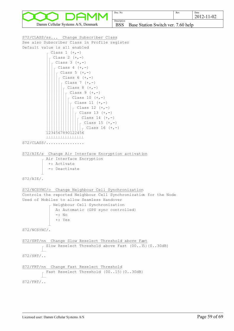
Damm Cellular Systems A/S, Denmark BSS Base Station Switch ver. 7.60 help
Doc. No. Rev. Date
Description
2012-11-02
S72/CLASS/ss... Change Subscriber Class
See also Subscriber Class in Profile register
Default value is all enabled
Class 1 (+,-)
Class 2 (+,-)
Class 3 (+,-)
Class 4 (+,-)
Class 5 (+,-)
Class 6 (+,-)
Class 7 (+,-)
Class 8 (+,-)
Class 9 (+,-)
Class 10 (+,-)
Class 11 (+,-)
Class 12 (+,-)
Class 13 (+,-)
Class 14 (+,-)
Class 15 (+,-)
Class 16 (+,-)
1234567890122456
S72/CLASS/................
S72/AIE/s Change Air Interface Encryption activation
Air Interface Encryption
+: Activate
-: Deactivate
S72/AIE/.
S72/NCSYNC/c Change Neighbour Cell Synchronization
Controls the reported Neighbour Cell Synchronization for the Node
Used of Mobiles to allow Seamless Handover
Neighbour Cell Synchronization
A: Automatic (GPS sync controlled)
-: No
+: Yes
S72/NCSYNC/.
S72/SRT/nn Change Slow Reselect Threshold above Fast
Slow Reselect Threshold above Fast (00..15)(0..30dB)
S72/SRT/..
S72/FRT/nn Change Fast Reselect Threshold
Fast Reselect Threshold (00..15)(0..30dB)
S72/FRT/..
Page 59 of 69Licensed user: Damm Cellular Systems A/S
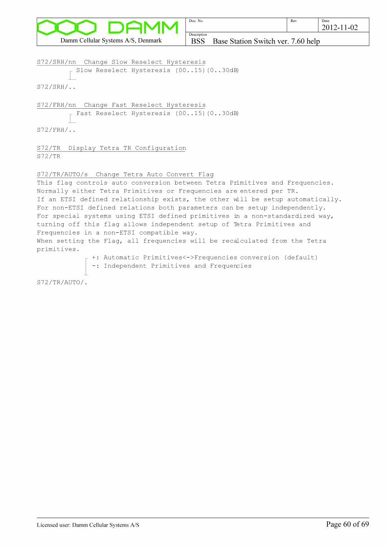
Damm Cellular Systems A/S, Denmark BSS Base Station Switch ver. 7.60 help
Doc. No. Rev. Date
Description
2012-11-02
S72/SRH/nn Change Slow Reselect Hysteresis
Slow Reselect Hysteresis (00..15)(0..30dB)
S72/SRH/..
S72/FRH/nn Change Fast Reselect Hysteresis
Fast Reselect Hysteresis (00..15)(0..30dB)
S72/FRH/..
S72/TR Display Tetra TR Configuration
S72/TR
S72/TR/AUTO/s Change Tetra Auto Convert Flag
This flag controls auto conversion between Tetra Primitives and Frequencies.
Normally either Tetra Primitives or Frequencies are entered per TR.
If an ETSI defined relationship exists, the other will be setup automatically.
For non-ETSI defined relations both parameters can be setup independently.
For special systems using ETSI defined primitives in a non-standardized way,
turning off this flag allows independent setup of Tetra Primitives and
Frequencies in a non-ETSI compatible way.
When setting the Flag, all frequencies will be recalculated from the Tetra
primitives.
+: Automatic Primitives<->Frequencies conversion (default)
-: Independent Primitives and Frequencies
S72/TR/AUTO/.
Page 60 of 69Licensed user: Damm Cellular Systems A/S
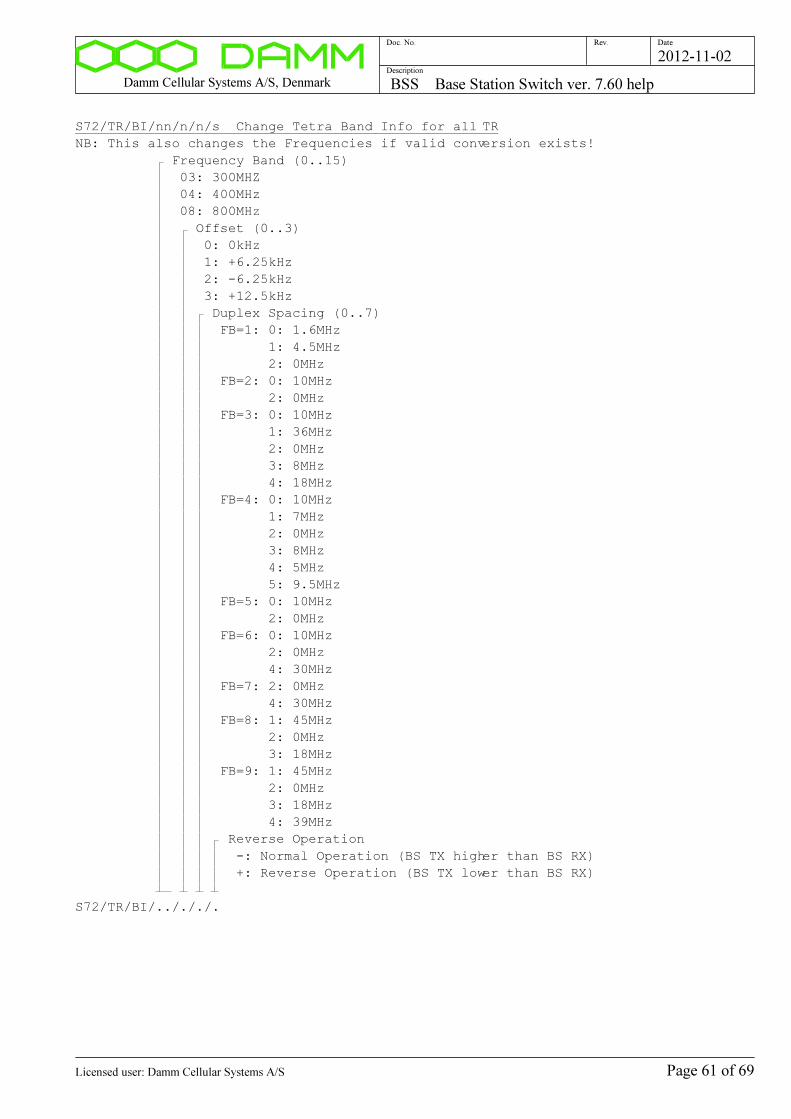
Damm Cellular Systems A/S, Denmark BSS Base Station Switch ver. 7.60 help
Doc. No. Rev. Date
Description
2012-11-02
S72/TR/BI/nn/n/n/s Change Tetra Band Info for all TR
NB: This also changes the Frequencies if valid conversion exists!
Frequency Band (0..15)
03: 300MHZ
04: 400MHz
08: 800MHz
Offset (0..3)
0: 0kHz
1: +6.25kHz
2: -6.25kHz
3: +12.5kHz
Duplex Spacing (0..7)
FB=1: 0: 1.6MHz
1: 4.5MHz
2: 0MHz
FB=2: 0: 10MHz
2: 0MHz
FB=3: 0: 10MHz
1: 36MHz
2: 0MHz
3: 8MHz
4: 18MHz
FB=4: 0: 10MHz
1: 7MHz
2: 0MHz
3: 8MHz
4: 5MHz
5: 9.5MHz
FB=5: 0: 10MHz
2: 0MHz
FB=6: 0: 10MHz
2: 0MHz
4: 30MHz
FB=7: 2: 0MHz
4: 30MHz
FB=8: 1: 45MHz
2: 0MHz
3: 18MHz
FB=9: 1: 45MHz
2: 0MHz
3: 18MHz
4: 39MHz
Reverse Operation
-: Normal Operation (BS TX higher than BS RX)
+: Reverse Operation (BS TX lower than BS RX)
S72/TR/BI/../././.
Page 61 of 69Licensed user: Damm Cellular Systems A/S
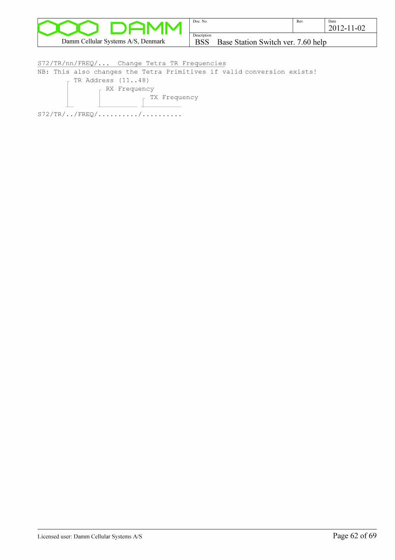
Damm Cellular Systems A/S, Denmark BSS Base Station Switch ver. 7.60 help
Doc. No. Rev. Date
Description
2012-11-02
S72/TR/nn/FREQ/... Change Tetra TR Frequencies
NB: This also changes the Tetra Primitives if valid conversion exists!
TR Address (11..48)
RX Frequency
TX Frequency
S72/TR/../FREQ/........../..........
Page 62 of 69Licensed user: Damm Cellular Systems A/S
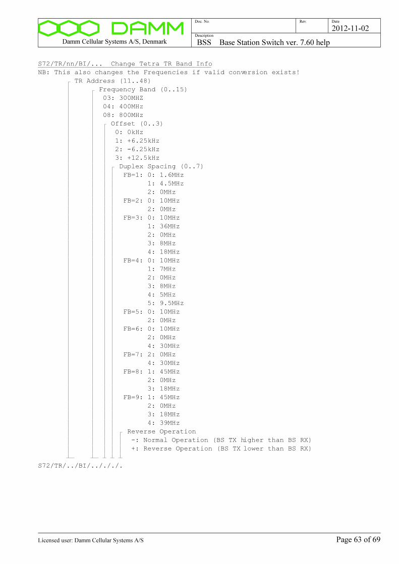
Damm Cellular Systems A/S, Denmark BSS Base Station Switch ver. 7.60 help
Doc. No. Rev. Date
Description
2012-11-02
S72/TR/nn/BI/... Change Tetra TR Band Info
NB: This also changes the Frequencies if valid conversion exists!
TR Address (11..48)
Frequency Band (0..15)
03: 300MHZ
04: 400MHz
08: 800MHz
Offset (0..3)
0: 0kHz
1: +6.25kHz
2: -6.25kHz
3: +12.5kHz
Duplex Spacing (0..7)
FB=1: 0: 1.6MHz
1: 4.5MHz
2: 0MHz
FB=2: 0: 10MHz
2: 0MHz
FB=3: 0: 10MHz
1: 36MHz
2: 0MHz
3: 8MHz
4: 18MHz
FB=4: 0: 10MHz
1: 7MHz
2: 0MHz
3: 8MHz
4: 5MHz
5: 9.5MHz
FB=5: 0: 10MHz
2: 0MHz
FB=6: 0: 10MHz
2: 0MHz
4: 30MHz
FB=7: 2: 0MHz
4: 30MHz
FB=8: 1: 45MHz
2: 0MHz
3: 18MHz
FB=9: 1: 45MHz
2: 0MHz
3: 18MHz
4: 39MHz
Reverse Operation
-: Normal Operation (BS TX higher than BS RX)
+: Reverse Operation (BS TX lower than BS RX)
S72/TR/../BI/../././.
Page 63 of 69Licensed user: Damm Cellular Systems A/S

Damm Cellular Systems A/S, Denmark BSS Base Station Switch ver. 7.60 help
Doc. No. Rev. Date
Description
2012-11-02
S72/TR/nn/CN/... Change Tetra TR Carrier Number
NB: This also changes the Frequencies if valid conversion exists!
TR Address (11..48)
Carrier Number:
0000..3999: Tetra Carrier Number
---- : Clear Carrier Number
S72/TR/../CN/....
S72/NC Display Tetra Neighbour Cell configuration list
S72/NC
S72/NC/+ Activate Tetra Neighbour Cell configuration list
Only active Cells from the list will be included in Neighbour Cell broadcast
This shall be selected for bigger systems
S72/NC/+
S72/NC/- De-activate Tetra Neighbour Cell List
All active Cells will be included in Neighbour Cell broadcast
This is for small systems only!
S72/NC/-
S72/NC/nnn/+ Add Tetra Neighbour Cell to list
Node Number (001..NodeMax)
S72/NC/.../+
S72/NC/nnn/- Remove Tetra Neighbour Cell from list
Node Number (001..NodeMax)
S72/NC/.../-
Page 64 of 69Licensed user: Damm Cellular Systems A/S
Damm Cellular Systems A/S, Denmark BSS Base Station Switch ver. 7.60 help
Doc. No. Rev. Date
Description
2012-11-02
Voice Gateway configuration:
S73 Display Voice Gateway configuration
S73
S73/CNFG/+ Activate Voice Gateway
Only possible if allowed of License Dongle
S73/CNFG/+
S73/CNFG/- Deactivate Voice Gateway
S73/CNFG/-
S73/ORG/ccc Change Voice Gateway Organization Number
000 : Calls allowed to/from all Home Organizations
001..999: Calls restricted to/from this Home Organization
+++ : Activates use of Organization Number Prefix
Outgoing: 3-digit Prefix is added to B-number.
Call from all Organizations are allowed.
Incoming: 3-digit Prefix shall be present on B-number.
Calls restricted to Prefix Home Organization (All
for 000)
Incoming Prefix is deleted.
S73/ORG/...
S73/CALLMAX/nnn Change max. number of Voice Gateway calls
Used to reduce the maximum number of simultaneous Voice Gateway
calls to less than defined in the License Dongle.
The value is limited to the License Dongle value.
Max. simultaneous calls (001..999)
S73/CALLMAX/...
S73/PRIORITY/nn Change PABX->Tetra Call Priority
Priority of the Tetra call at call setup from PSTN
Call Priority (00..15)
S73/PRIORITY/..
S73/REG/s Change Voice Gateway Registration Selection
Activates the use of SIP registration to the remote PABX/Gateway
It is recommended to use registration
+: Use SIP registration (default)
-: Do not use SIP registration
S73/REG/.
Page 65 of 69Licensed user: Damm Cellular Systems A/S
Damm Cellular Systems A/S, Denmark BSS Base Station Switch ver. 7.60 help
Doc. No. Rev. Date
Description
2012-11-02
S73/NAME/cc..c Change Voice Gateway Registration Name
Name to use for Registration on remote PABX/Gateway
Name (0..64 characters)
S73/NAME/................................................................
S73/PASSWORD/cc..c Change Voice Gateway Registration Name
Name to use for Registration on remote PABX/Gateway
Password (0..32 characters)
S73/PASSWORD/................................
S73/IPADDR/... Change Voice Gateway Remote IP Address
IP Address of the PABX or SIP proxy conneced to the BSC
IP address
S73/IPADDR/...............
S73/PORT/LOC/nnnnn Change Voice Gateway Local IP Port
Defalut value is 05060
Local IP Port (00001..65535)
S73/PORT/LOC/.....
S73/PORT/REM/nnnnn Change Voice Gateway Remote IP Port
Defalut value is 05060
Remote IP Port (00001..65535)
S73/PORT/REM/.....
Page 66 of 69Licensed user: Damm Cellular Systems A/S

Damm Cellular Systems A/S, Denmark BSS Base Station Switch ver. 7.60 help
Doc. No. Rev. Date
Description
2012-11-02
Packet Data Gateway configuration:
S74 Display Packet Data Gateway configuration
S74
S74/CNFG/+ Activate Packet Data Gateway
Only possible if allowed of License Dongle
S74/CNFG/+
S74/CNFG/- Deactivate Packet Data Gateway
S74/CNFG/-
S74/RIP/s Change Packet Data Gateway RIP selection
Controls output of Routing Information Protocol ver. 2 according
to RFC2453.
If activated, RIP message with IP Address and Mask will be
send every 30 second to multicast address 224.0.0.9 UDP port 520.
To be received of the default gateway for the IP segment, where
RIPv2 shall be activated.
When RIP is activated, a static route in the default gateway
pointing to the Packet Data Gateway is no longer needed.
Note, that RIP is needed for switching between redundant BSC's.
+: Activate RIPv2 output (default)
-: Disable RIPv2 output
S74/RIP/.
Page 67 of 69Licensed user: Damm Cellular Systems A/S
Damm Cellular Systems A/S, Denmark BSS Base Station Switch ver. 7.60 help
Doc. No. Rev. Date
Description
2012-11-02
Application Gateway configuration:
S75 Display Application Gateway configuration
S75
S75/CNFG/+ Activate Application Gateway
Only possible if allowed of License Dongle
S75/CNFG/+
S75/CNFG/- Deactivate Application Gateway
S75/CNFG/-
S75/CONNMAX/nnn Change max. Application Gateway connections
Used to reduce the maximum number of simultaneous connected Applications to a
lower value as the limit in the License Dongle.
The value is automatically limited to the lowest of the compiled
maximum value and the License Dongle value.
Max. Application Gateway connections (001..999)
S75/CONNMAX/...
S75/STREAMMAX/nnn Change max. Application Gateway Circuit Mode Streams
Used to reduce the maximum total number of simultaneous Circuit Mode
streams for the Application Gateway to lower value than the compiled maximum.
The value is automatically limited to the compiled maximum.
Max. Application Gateway Circuit Mode Streams (001..999)
S75/STREAMMAX/...
S75/CONNTIMEOUT/nnn Connection Timeout
Timeout for the Application connection.
Used to timeout connection at missing Application response.
Default value is 2 minutes.
Connection Timeout (001..255 [minutes])
S75/CONNTIMEOUT/...
S75/DISCRLIST/s Change Application Gateway Discreet Listening
Controls Discreet Listening activation in Application Gateway
+: Activate Discreet Listening support
-: Disable Discreet Listening support (default)
S75/DISCRLIST/.
Page 68 of 69Licensed user: Damm Cellular Systems A/S
Damm Cellular Systems A/S, Denmark BSS Base Station Switch ver. 7.60 help
Doc. No. Rev. Date
Description
2012-11-02
Terminal Gateway configuration:
S76 Display Terminal Gateway configuration
S76
S76/CNFG/+ Activate Terminal Gateway
Only possible if allowed of License Dongle
S76/CNFG/+
S76/CNFG/- Deactivate Terminal Gateway
S76/CNFG/-
S76/CONNMAX/nnn Change max. Terminal Gateway connections
Used to reduce the maximum number of simultaneous connected Terminals to a
lower value as the limit in the License Dongle.
The value is automatically limited to the lowest of the compiled
maximum value and the License Dongle value.
Max. Terminal Gateway connections (001..999)
S76/CONNMAX/...
S76/STREAMMAX/nnn Change max. Terminal Gateway Circuit Mode Streams
Used to reduce the maximum total number of simultaneous Circuit Mode
streams for the Terminal Gateway to lower value than the compiled maximum.
The value is automatically limited to the compiled maximum.
Max. Terminal Gateway Circuit Mode Streams (001..999)
S76/STREAMMAX/...
S76/CONNTIMEOUT/nnn Connection Timeout
Timeout for the Terminal connection.
Used to timeout connection at missing Terminal response.
Default value is 2 minutes.
Connection Timeout (001..255 [minutes])
S76/CONNTIMEOUT/...
Page 69 of 69Licensed user: Damm Cellular Systems A/S
Damm Cellular Systems A/S, Denmark BS Base Station ver. 7.60 help
Doc. No. Rev. Date
Description
2012-11-02
BS Base Station ver. 7.60 help
Functional Description
Page 1 of 34Licensed user: Damm Cellular Systems A/S
Damm Cellular Systems A/S, Denmark BS Base Station ver. 7.60 help
Doc. No. Rev. Date
Description
2012-11-02
BS Address selection
Page 2 of 34Licensed user: Damm Cellular Systems A/S
Damm Cellular Systems A/S, Denmark BS Base Station ver. 7.60 help
Doc. No. Rev. Date
Description
2012-11-02
BSC41x UART Address selection
AU BSC41x UART ADDRESS SELECTION
AU Display BSC41x UART selection
AU
AU+ Select BSC41x UART Address
AU+
AU- Deselect BSC41x UART Address
AU-
AU/FORCED Forced BSC41x UART Address select
Warning: This will disconnect existing user!!!
AU/FORCED
Command description:
Page 3 of 34Licensed user: Damm Cellular Systems A/S
Damm Cellular Systems A/S, Denmark BS Base Station ver. 7.60 help
Doc. No. Rev. Date
Description
2012-11-02
Device Address selection
A DEVICE ADDRESS COMMAND
A Display Address
NB: If BSC41x UART is selected, command is send on UART
and response is coming from selected Device
A
Ann Select BS41x TR Address
TR Address
11..48: TR11..TR48 Transceiver
A..
APnn Select BS41x PS Address
PS Address
11..47: PS11..PS47 Power Supply
AP..
ATnn Select BS41x TC Address
TC Address
11..42: TC11..TC12 TX Combiner
AT..
Command description:
Page 4 of 34Licensed user: Damm Cellular Systems A/S

Damm Cellular Systems A/S, Denmark BS Base Station ver. 7.60 help
Doc. No. Rev. Date
Description
2012-11-02
Software Version:
H00 DISPLAY SOFTWARE VERSION
H00 Display software version
H00
H00/A Display all software version numbers
H00/A
H00/C Display compiler options
H00/C
H00/OM Display OM TCP Connection status
H00/OM
H00/BSC Display OM BSC Connection status
H00/BSC
Command description:
Page 5 of 34Licensed user: Damm Cellular Systems A/S
Damm Cellular Systems A/S, Denmark BS Base Station ver. 7.60 help
Doc. No. Rev. Date
Description
2012-11-02
BS Activation Control
H02 BS ACTIVATION CONTROL
H02 Display BS Activation Status
H02
H02/ACTIVATE BS Activation Request
Sends Activation Request to other BS
H02/ACTIVATE
H02/STANDBY/s Change Forced BSC Standby
+: Forced Standby
-: Normal
H02/STANDBY/.
Command description:
Page 6 of 34Licensed user: Damm Cellular Systems A/S

Damm Cellular Systems A/S, Denmark BS Base Station ver. 7.60 help
Doc. No. Rev. Date
Description
2012-11-02
Alarms
H03 ALARMS
H03 Display BS Alarm state
H03
H03/A Display BSC Alarm Flags
H03/A
H03/IN Display Alarm Inputs
H03/IN
Command description:
Page 7 of 34Licensed user: Damm Cellular Systems A/S
Damm Cellular Systems A/S, Denmark BS Base Station ver. 7.60 help
Doc. No. Rev. Date
Description
2012-11-02
Synchronization Status
H12 SYNCHRONIZATION STATUS
H12 Display Synchronization Status
H12
H12/IN Display Sync Inputs
H12/IN
H12/MASTER Display Master Table
H12/MASTER
H12/PPS Display 1PPS Inputs
H12/PPS
H12/HIST Display OCXO Sync History
H12/HIST
Command description:
Page 8 of 34Licensed user: Damm Cellular Systems A/S
Damm Cellular Systems A/S, Denmark BS Base Station ver. 7.60 help
Doc. No. Rev. Date
Description
2012-11-02
BS Antenna Status
H13 BS ANTENNA STATUS
H13 Display Radio Cell Antenna Status
H13
Command description:
Page 9 of 34Licensed user: Damm Cellular Systems A/S

Damm Cellular Systems A/S, Denmark BS Base Station ver. 7.60 help
Doc. No. Rev. Date
Description
2012-11-02
TR Status
H15 TR STATUS
H15 Display TR Status
H15
H15/c Display TR Status
F: Frequencies/Power
P: GPS Positions
V: Versions
L: Frequency and Power Limits
E: External Alarms
H15/.
H15/nn/A Display TR Alarm Flags
TR Address (11..48)
H15/../A
Command description:
Page 10 of 34Licensed user: Damm Cellular Systems A/S
Damm Cellular Systems A/S, Denmark BS Base Station ver. 7.60 help
Doc. No. Rev. Date
Description
2012-11-02
PS Status
H16 PS STATUS
H16 Display PS Status
H16
H16/AL Display PS411 Alarm Flags
H16/AL
H16/REC Display PS411 Rectifier status
H16/REC
H16/OUT Display PS411 +14V/+26V status
H16/OUT
H16/LED Display PS411 LED status
H16/LED
H16/nn Display PS411 Status
PS Address (11..47)
H16/..
Command description:
Page 11 of 34Licensed user: Damm Cellular Systems A/S

Damm Cellular Systems A/S, Denmark BS Base Station ver. 7.60 help
Doc. No. Rev. Date
Description
2012-11-02
OCXO:
H31 OCXO SYNC
H31 Display OCXO Sync
H31
H31/IN/c Change Sync Input selection
-: Auto Select
F: Forced Free Running
G: Forced GPS RX Lock
0: Forced External 0 Lock
1: Forced External 1 Lock
2: Forced External 2 Lock
H31/IN/.
H31/SET Set OCXO Free Run adjust value to current DAC value
H31/SET
H31/SET/nn.nnn Set OCXO Free Run value
00.000 to 99.999 [%]
H31/SET/......
H31/SAVE Save OCXO Free Run adjust value in Flash
H31/SAVE
H31/STEP/nn.nnn Simulate a PLL Frequency Step
00.000 to 99.999 [%]
H31/STEP/......
Command description:
Page 12 of 34Licensed user: Damm Cellular Systems A/S
Damm Cellular Systems A/S, Denmark BS Base Station ver. 7.60 help
Doc. No. Rev. Date
Description
2012-11-02
Internal GPS RX:
H32 INTERNAL GPS
H32 Display Internal GPS RX Status
H32
H32/VER Display GPS Module Version
H32/VER
H32/N Display next Internal GPS message
Hint: Use the C/H32/N command to display continuously
H32/N
H32/SETUP Setup GPS RX Module
Setup the Internal GPS RX Module and saves the configuration in GPS RX flash
This command shall be executed when a new GPS RX module is installed
H32/SETUP
H32/SEND/cc..c Send Command to GPS RX Module
This command is for testing only
NMEA command
H32/SEND/....................................................................
Command description:
Page 13 of 34Licensed user: Damm Cellular Systems A/S
Damm Cellular Systems A/S, Denmark BS Base Station ver. 7.60 help
Doc. No. Rev. Date
Description
2012-11-02
CMoIP Switch
H34 CMOIP SWITCH
H34 Display all CMoIP Connections
H34
H34/nn/n Display one CMoIP Connection
TR Address (11..48)
Tetra Timeslot (1..4)
H34/../.
H34/nn/n/... CMoIP Multicast Connect
TR Address (11..48)
Tetra Timeslot (1..4)
Multicast IP Address
H34/.././...............
H34/nn/n/REL CMoIP Multicast Release
TR Address (11..48)
Tetra Timeslot (1..4)
H34/.././REL
H34/C Clear Message Counters
H34/C
Command description:
Page 14 of 34Licensed user: Damm Cellular Systems A/S
Damm Cellular Systems A/S, Denmark BS Base Station ver. 7.60 help
Doc. No. Rev. Date
Description
2012-11-02
Message Trace:
H48 MESSAGE TRACE
H48 Display Message Trace
H48
H48- Stop all Message Traces
H48-
H48/C Clear Trace Counters
H48/C
H48/UDP/+ Activate Trace output to UDP
UDP output counter will be cleared
H48/UDP/+
H48/UDP/- Stop Trace output to UDP
H48/UDP/-
H48/UDP/nnn... Change Trace UDP address+port
UDP IP address
UDP port number (default 42397)
H48/UDP/.............../.....
H48/FILE/+ Open Trace output file
File will be cleared if existing
File output counter will be cleared
H48/FILE/+
H48/FILE/- Close Trace output file
H48/FILE/-
H48/FILE/cc..c Change Trace filename
File will be closed if open
NB: There shall be write access permission to the file location
Filename (e.g. C:\Tetra\Work\Trace1.lan)
H48/FILE/.........................................................
H48/n/s Start/Stop Trace
Trace Number (1..4)
Action
+: Start Trace
-: Stop Trace
H48/./.
Page 15 of 34Licensed user: Damm Cellular Systems A/S
Damm Cellular Systems A/S, Denmark BS Base Station ver. 7.60 help
Doc. No. Rev. Date
Description
2012-11-02
H48/n/nn/n/c Setup Trace Test Point
Trace Number (1..4)
TR (11..18)
Timeslot (1..4)
Test Point
U: Unencrypted
E: Encrypted (unencrypted if no AIE)
H48/./.././.
Command description:
The H48 Commands control the TR Signalling Trace functionality.
Up to 4 different Test Points can be activated on any TR and timeslot in total.
Both Downlink and Uplink traffic is monitored on the TR's, and excludes or
includes
Air Interface Encryption.
The output from the Test Points can be output realtime in UDP messages, and can
also be written to a file, either located locally or on a remote Computer.
The output can be analyzed with the Tetra Protocol Analyzer from fjord-e-
design.
Page 16 of 34Licensed user: Damm Cellular Systems A/S
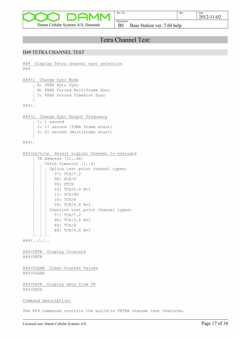
Damm Cellular Systems A/S, Denmark BS Base Station ver. 7.60 help
Doc. No. Rev. Date
Description
2012-11-02
Tetra Channel Test:
H49 TETRA CHANNEL TEST
H49 Display Tetra channel test selection
H49
H49/c Change Sync Mode
A: PRBS Auto Sync
M: PRBS Forced Multiframe Sync
T: PRBS Forced Timeslot Sync
H49/.
H49/n Change Sync Output Frequency
1: 1 second
2: 17 second (TDMA frame start)
3: 51 second (Multiframe start)
H49/.
H49/nn/n/nn Select Logical Channel to evaluate
TR Address (11..48)
Tetra Timeslot (1..4)
Uplink test point channel types:
07: TCH/7.2
08: SCH/F
09: STCH
10: TCH/2.4 N=1
11: SCH/HU
16: TCH/S
18: TCH/4.8 N=1
Downlink test point channel types:
57: TCH/7.2
60: TCH/2.4 N=1
66: TCH/S
68: TCH/4.8 N=1
H49/.././..
H49/CNTR Display Counters
H49/CNTR
H49/CLEAR Clear Counter Values
H49/CLEAR
H49/DATA Display data from TR
H49/DATA
Command description:
The H49 commands controls the build-in TETRA channel test features.
Page 17 of 34Licensed user: Damm Cellular Systems A/S
Damm Cellular Systems A/S, Denmark BS Base Station ver. 7.60 help
Doc. No. Rev. Date
Description
2012-11-02
When channel test is activated, a test point at the output from or input to
the receiver is selected. Received bursts including status will be analyzed
and BER/MER calculated.
When channel test is activated, the BS421 TX switches to uplink mode and
generates the selected channel type. When TX is keyed and RFTL activated,
an RX input signal can be generated for the testing.
Alternatively, a test signal can be generated from an external source, e.g.
an R&S SMIQ or Anritsu signal generator
The uplink test point is intended for normal receiver channel tests.
The downlink test point is intented for test of received traffic from the
lines.
Page 18 of 34Licensed user: Damm Cellular Systems A/S
Damm Cellular Systems A/S, Denmark BS Base Station ver. 7.60 help
Doc. No. Rev. Date
Description
2012-11-02
DC Voltmeter
H60 DC VOLTMETER
H60 Display DC Voltmeter
H60
Command description:
Page 19 of 34Licensed user: Damm Cellular Systems A/S

Damm Cellular Systems A/S, Denmark BS Base Station ver. 7.60 help
Doc. No. Rev. Date
Description
2012-11-02
Co-Processor
*H61 CO-PROCESSOR
H61 Display Co-Processor Status
H61
H61/Fhhh0 Display DPRAM
DPRAM Address (F8000..FFFF0)
H61/F...0
H61/MEM/hhhhh Read CP Memory
CP Memory Address (00000..FFFFF)
H61/MEM/.....
H61/PORT/hhhhh Read CP Port
CP Port Address (0000..FFFF)
H61/PORT/....
Command description:
Page 20 of 34Licensed user: Damm Cellular Systems A/S
Damm Cellular Systems A/S, Denmark BS Base Station ver. 7.60 help
Doc. No. Rev. Date
Description
2012-11-02
BS<->BSC Message test queue
H63 BS<->BSC MESSAGE TEST QUEUE
H63 Display BSC Link Status
H63
H63/N Display next BSC message
H63/N
H63/N+ Display next BSC message extended
H63/N+
H63/S Set BSC message test queue to start
H63/S
H63/C Clear BSC message test queue
H63/C
H63/s BSC Message suppression
+: Display all BSC messages
-: Suppress some BSC messages (default)
H63/.
H63/n/hh/hh..hh Send Message to BSC
BSC Number (1..2)
Message ID (00..FF hex)
Payload (hex)
0 02 04 06 08 10 12 14 16 18 20 22 24 26 28 30 32 34
ÿ ¿ ¿ ¿ ¿ ¿ ¿ ¿ ¿ ¿ ¿ ¿ ¿ ¿ ¿ ¿ ¿ ¿ ¿ ¿ ¿ ¿ ¿ ¿ ¿ ¿ ¿ ¿ ¿ ¿ ¿ ¿ ¿ ¿ ¿
H63/./../......................................................................
Command description:
Page 21 of 34Licensed user: Damm Cellular Systems A/S
Damm Cellular Systems A/S, Denmark BS Base Station ver. 7.60 help
Doc. No. Rev. Date
Description
2012-11-02
UDP Message test queue
H64 UDP MESSAGE TEST QUEUE
H64 Display UDP Link Status
H64
H64/N Display next UDP message
H64/N
H64/N+ Display next UDP message extended
H64/N+
H64/S Set UDP message test queue to start
H64/S
H64/C Clear UDP message test queue
H64/C
H64/s UDP Message suppression
+: Display all UDP messages
-: Suppress some UDP messages (default)
H64/.
H64/hh/hh..hh Send Message to Redundant BS
Message ID (00..FF hex)
Payload (hex)
0 02 04 06 08 10 12 14 16 18 20 22 24 26 28 30 32 34
ÿ ¿ ¿ ¿ ¿ ¿ ¿ ¿ ¿ ¿ ¿ ¿ ¿ ¿ ¿ ¿ ¿ ¿ ¿ ¿ ¿ ¿ ¿ ¿ ¿ ¿ ¿ ¿ ¿ ¿ ¿ ¿ ¿ ¿ ¿
H64/../......................................................................
Command description:
Page 22 of 34Licensed user: Damm Cellular Systems A/S
Damm Cellular Systems A/S, Denmark BS Base Station ver. 7.60 help
Doc. No. Rev. Date
Description
2012-11-02
BS<->TR Message test queue
H65 BS<->TR MESSAGE TEST QUEUE
H65 Display TR Link Status
H65
H65/PS Display PS411 Link Status
H65/PS
H65/N Display next TR message
H65/N
H65/N+ Display next TR message extended
H65/N+
H65/S Set TR message test queue to start
H65/S
H65/C Clear TR message test queue
H65/C
H65/s TR Message suppression
+: Display all TR messages
-: Suppress some TR messages (default)
H65/.
H65/nn/hh/hh..hh Send Message to TR
TR Address (11..48)
Message ID (00..FF hex)
Payload (hex)
0 02 04 06 08 10 12 14 16 18 20 22 24 26 28 30 32
34
ÿ ¿ ¿ ¿ ¿ ¿ ¿ ¿ ¿ ¿ ¿ ¿ ¿ ¿ ¿ ¿ ¿ ¿ ¿ ¿ ¿ ¿ ¿ ¿ ¿ ¿ ¿ ¿ ¿ ¿ ¿ ¿ ¿ ¿ ¿
H65/../../.....................................................................
.
H65/PS/nn/hh/hh..hh Send Message to PS411
PS Address (11..47)
Message ID (00..FF hex)
Payload (hex)
0 02 04 06 08 10 12 14 16 18 20 22 24 26 28 30 32
34
ÿ ¿ ¿ ¿ ¿ ¿ ¿ ¿ ¿ ¿ ¿ ¿ ¿ ¿ ¿ ¿ ¿ ¿ ¿ ¿ ¿ ¿ ¿ ¿ ¿ ¿ ¿ ¿ ¿ ¿ ¿ ¿ ¿ ¿ ¿
H65/PS/../../..................................................................
....
Command description:
Page 23 of 34Licensed user: Damm Cellular Systems A/S
Damm Cellular Systems A/S, Denmark BS Base Station ver. 7.60 help
Doc. No. Rev. Date
Description
2012-11-02
Program Download
H68 PROGRAM DOWNLOAD
H68 Display Program Download Status
H68
H68/TR412 Display TR412 Program Download Status
Command only available on active BSC
H68/TR412
H68/TR412/cc TR412 Program Download command
1) Sends Program Download command to TR412
2) TR412 restarts in Boot Mode, erases the flash program area
and sends download request to BSC.
3) BSC reads ...\Pgm\TR412\TR412.bin file from disk
4) BSC starts download to reprogram TR412 Flash
5) TR412 restarts again and resumes normal operation
NB: Boot Part of TR412 software is NOT updated.
Boot version can be displayed with the TR412 '00/A' command.
Command only available on active BSC
A : All TR
11..48: TR11..TR48
H68/TR412/..
Command description:
Page 24 of 34Licensed user: Damm Cellular Systems A/S

Damm Cellular Systems A/S, Denmark BS Base Station ver. 7.60 help
Doc. No. Rev. Date
Description
2012-11-02
BS configuration:
H70 Display command function
H70
H70/SAVE Save BS configuration in file
Note that BS Configuration changes are saved automatically
H70/SAVE
Page 25 of 34Licensed user: Damm Cellular Systems A/S
Damm Cellular Systems A/S, Denmark BS Base Station ver. 7.60 help
Doc. No. Rev. Date
Description
2012-11-02
Common system configuration:
H71 Display Common BS configuration
H71
H71/CNFG/+ Activate BS
H71/CNFG/+
H71/CNFG/- Deactivate BS
H71/CNFG/-
H71/BSNO/n Change BS Number
BS Number (1..2)
H71/BSNO/.
H71/RACKNO/n Change Rack Number
Rack number (1st digit of Address)
Rack Number (1..4)
H71/RACKNO/.
H71/REDBS/s Change Redundant BS Configuration
Redundant BS Configuration Flag
+: Configured
-: Not configured
H71/REDBS/.
H71/REDBS/... Change Redundant BS IP Address
IP Address
H71/REDBS/...............
H71/BSC/n/s Change BSC Configuration
BSC number (1..2)
BSC Configuration Flag
+: Select BSC
-: Deselect BSC
H71/BSC/./.
H71/BSC/n/nnn.nnn.nnn.nnn Change BSC IP Address
BSC number (1..2)
IP Address
H71/BSC/./...............
H71/CMOIP Display CMoIP selection
NB: Command not available in Damm TetraFlex
H71/CMOIP
Page 26 of 34Licensed user: Damm Cellular Systems A/S
Damm Cellular Systems A/S, Denmark BS Base Station ver. 7.60 help
Doc. No. Rev. Date
Description
2012-11-02
H71/CMOIP/s Change CMoIP selection
NB: Command not available in Damm TetraFlex
CMoIP Selection
-: CMoIP Multicast
+: CMoIP to BSS
H71/CMOIP/.
H71/CMOIP/n/... Change CMoIP BSS IP Address
NB: Command not available in Damm TetraFlex
Active BSS number (1..2)
IP Address
H71/CMOIP/./...............
Page 27 of 34Licensed user: Damm Cellular Systems A/S
Damm Cellular Systems A/S, Denmark BS Base Station ver. 7.60 help
Doc. No. Rev. Date
Description
2012-11-02
Synchronization configurations
H72 Synchronisation
H72 Display BSC412 Sync selection
H72
H72/MASTER/c Change Master Priority
Changes the Synchronization Priority for the BS
Master 1 shall be selected for the Primary Master in a cell.
Master 2..4 shall be selected for the Backup Masters in a cell.
Master 0 shall only be selected if the BS is Global Master used to
synchronize other cells.
Warning: The Master selections shall be unique within a Radio Cell
0: Master 0 (For Global Master) (Highest Priority)
1: Master 1 (For Primary Master in a Cell)
2: Master 2
3: Master 3
4: Master 4 (Lowest Priority)
S: Slave
H72/MASTER/.
H72/CENTSECOFS/snnnnnnnnnn Change Century Second offset
Used to change the Century Second offset, where all TETRA counters started
For standard Damm TetraFlex this value shall be 0.
Century Second Offset
DAMM: +0000000000 [2000-01-01 00:00:00 UTC]
EADS: +0031536013 [1999-01-01 00:00:00 GPS]
H72/CENTSECOFS/...........
H72/CENTSECOFS/DAMM Change Century Second offset to DAMM
Used to clear Century Seconds offset for DAMM timing
Value: 0 for 2000-01-01 00:00:00 UTC
H72/CENTSECOFS/DAMM
H72/CENTSECOFS/EADS Change Century Second offset to EADS
Used to setup the Centrury Seconds offset for EADS timing
Value: +31536013 (1 year + 13 leap seconds) for 1999-01-01 00:00:00 GPS
H72/CENTSECOFS/EADS
H72/GPSRXOFS/snnn.n Change GPS RX offset
Used to change the GPS RX time offset
For standard Damm TetraFlex this value shall be 0.
GPS RX offset
DAMM: +000.0 [usec.]
EADS: +111.1 [usec.]
H72/GPSRXOFS/......
Page 28 of 34Licensed user: Damm Cellular Systems A/S
Damm Cellular Systems A/S, Denmark BS Base Station ver. 7.60 help
Doc. No. Rev. Date
Description
2012-11-02
H72/GPSRXOFS/DAMM Change GPS RX offset to DAMM
Used to clear the GPS RX offset for DAMM timing
Value: +000.0 userc.
H72/GPSRXOFS/DAMM
H72/GPSRXOFS/EADS Change GPS RX offset to EADS
Used to setup the GPS RX offset for EADS timing
Value: -055.6 usec.
H72/GPSRXOFS/EADS
H72/IN/n/s Activate/Deactivate BSC412 Sync Input
Input
G: GPS RX
0: Ext. 0 (Other BSC)
1: Ext. 1
2: Ext. 2
Activate/Deactivate
+: Configured
-: Not configured
H72/IN/./.
H72/IN/n/... Setup BSC412 External Sync Input
Input
1: External 1
2: External 2
Primary Flag
-: Not Primary Input (Normal)
+: Primary Input (For Remote Primary Reference only)
IP Address
Cable Delay in usec. (000.0..999.9)
H72/IN/././.............../.....
H72/OUT Display BSC412 Sync Message Output Table
H72/OUT
H72/OUT/... Add/Remove BSC412 Sync Message Output
All units connected to the 1PPS output shall be added here
Max. 30 IP Addresses can be configured
Outputs are NOT active if Sync Slave Priority
IP Address (000..255)
Action:
+: Add
-: Remove
H72/OUT/.............../.
Command description:
The TETRA Base Station TR's need to be time synchronized to operate correctly.
Most importantly, all TR's in a radio cell shall be time synchronized together
Page 29 of 34Licensed user: Damm Cellular Systems A/S
Damm Cellular Systems A/S, Denmark BS Base Station ver. 7.60 help
Doc. No. Rev. Date
Description
2012-11-02
to
ensure correct timing for the mobiles, when switching from the control channel
to
a traffic channel on another TR.
For a multi-cell systems, all radio cells are also recommended to be time
synchronized together
to enable use of seamless handover (cell re-selection).
The Damm BS system is provided with a flexible system to provide
synchronization
between individual Transceivers. Build-in GPS Receivers give absolute time
synchronization to the radio cells. External Inputs can also be marked as
Primary
Sync References.
When as BS is Network locked, automatic frequency correction of the Master
Oscillator (RX and TX carrier frequencies) are provided, and Seamless Handover
to
other Network Synchronized Cells are activated.
The BS can be setup to run as either Sync Master 0..4 or Slave. The Masters
shall preferably be provided with GPS antennas or an External Primary Sync
source.
The remaining BS's shall be setup as Slave and do not need a GPS antenna.
The BS is provided with one External 1PPS (1 Pulse Per Second) output and
three external 1PPS inputs. The Slaves shall have their external 1PPS inputs
connected to Masters.
In addition to the hardware 1PPS, sync messages are send every second on IP
from the Masters to attached BS's.
A Master will indicate Master Mode, if:
1) Synchronized to the internal GPS RX or
2) Synchronized to an External Input marked as Primary and indicating
Master Mode
Master 0 priority:
1) Int. GPS RX
2) Ext. Master 1, Master Mode
3) Ext. Master 2, Master Mode
4) Ext. Master 3, Master Mode
5) Ext. Master 4, Master Mode
6) Ext. Master 1, Resync-only
7) Ext. Master 2, Resync-only
8) Ext. Master 3, Resync-only
9) Ext. Master 4, Resync-only
10)Int. Free-Run
Master 1 priority:
1) Ext. Master 0, Master Mode
2) Int. GPS RX
Page 30 of 34Licensed user: Damm Cellular Systems A/S
Damm Cellular Systems A/S, Denmark BS Base Station ver. 7.60 help
Doc. No. Rev. Date
Description
2012-11-02
3) Ext. Master 2, Master Mode
4) Ext. Master 3, Master Mode
5) Ext. Master 4, Master Mode
6) Ext. Master 0
7) Ext. Master 2, Resync-only
8) Ext. Master 3, Resync-only
9) Ext. Master 4, Resync-only
10)Int. Free-Run
Master 2 priority:
1) Ext. Master 0, Master Mode
2) Ext. Master 1, Master Mode
3) Int. GPS RX
4) Ext. Master 3, Master Mode
5) Ext. Master 4, Master Mode
6) Ext. Master 0
7) Ext. Master 1
8) Ext. Master 3, Resync-only
9) Ext. Master 4, Resync-only
10)Int. Free-Run
Master 3 priority:
1) Ext. Master 0, Master Mode
2) Ext. Master 1, Master Mode
3) Ext. Master 2, Master Mode
4) Int. GPS RX
5) Ext. Master 4, Master Mode
6) Ext. Master 0
7) Ext. Master 1
8) Ext. Master 2
9) Ext. Master 4, Resync-only
10)Int. Free-Run
Master 4 priority:
1) Ext. Master 0, Master Mode
2) Ext. Master 1, Master Mode
3) Ext. Master 2, Master Mode
4) Ext. Master 3, Master Mode
5) Int. GPS RX
6) Ext. Master 0
7) Ext. Master 1
8) Ext. Master 2
9) Ext. Master 3
10)Int. Free-Run
Slave priority:
1) Ext. Master 0, Master Mode
2) Ext. Master 1, Master Mode
3) Ext. Master 2, Master Mode
4) Ext. Master 3, Master Mode
5) Ext. Master 4, Master Mode
6) Ext. Master 0
7) Ext. Master 1
8) Ext. Master 2
Page 31 of 34Licensed user: Damm Cellular Systems A/S
Damm Cellular Systems A/S, Denmark BS Base Station ver. 7.60 help
Doc. No. Rev. Date
Description
2012-11-02
9) Ext. Master 3
10)Ext. Master 4
11)Int. GPS RX
12)Int. Free-Run
If no GPS synchronized Master or higher prioritized free-running Master is
available at re-start, Masters will try initially to synchronize to lower
prioritized free-running Masters.
A BS will resync automatically after a short time, if Century Second
and Phase Detector are out of sync with a valid sync source.
Masters shall be setup even if GPS antennas are not used and internal GPS RX
are deselected, to ensure proper synchronization between all TR's.
Typical BS41x configuration without redundant BSC412:
BS activated on BSC412: Sync Master 1
Typical BS41x configuration with redundant BSC412:
BSC412-11: Sync Master 1
BSC412-12: Sync Master 2
Typical dual-rack BS41x configuration with redundant BSC412 in each rack:
BSC412-11: Sync Master 1
BSC412-12: Sync Master 2
BSC412-21: Sync Master 3
BSC412-22: Sync Master 4
Page 32 of 34Licensed user: Damm Cellular Systems A/S
Damm Cellular Systems A/S, Denmark BS Base Station ver. 7.60 help
Doc. No. Rev. Date
Description
2012-11-02
Radio Cell configuration
H73 Display Radio Cell configuration
H73
H73/RXDIV/c Change RX Diversity configuration
RX diversity configuration
D: Diversity
A: RX-A antenna only
B: RX-B antenna only
H73/RXDIV/.
H73/RXPREGAIN/n.n Change RX Pre-Gain
TMA pregain in dB (0.0..9.9, nom. 6.0)
H73/RXPREGAIN/...
H73/RXBAND/... Change RX frequency band
Define the RX frequency band of the cell
Shall match the TMA filter adjustment
RX low frequency
nnn.nnnnnn: Frequency [MHz]
000.000000: Not setup
RX high frequency
nnn.nnnnnn: Frequency [MHz]
000.000000: Not setup
H73/RXBAND/........../..........
H73/TXBAND/... Change TX frequency band
Define the TX frequency band of the cell
Shall match the TX filter adjustment
TX low frequency
nnn.nnnnnn: Frequency [MHz]
000.000000: Not setup
TX high frequency
nnn.nnnnnn: Frequency [MHz]
000.000000: Not setup
H73/TXBAND/........../..........
H73/TXANT/... Change TX antenna alarm settings
TX antenna L1 alarm setting (06..16 [dB Return Loss])
TX antenna L2 alarm setting (06..16 [dB Return Loss])
Minimum forward power (0.2..9.9 [W])
Minimum reflected power (0.01..0.99 [W])
H73/TXANT/../../.../0...
Page 33 of 34Licensed user: Damm Cellular Systems A/S
Damm Cellular Systems A/S, Denmark BS Base Station ver. 7.60 help
Doc. No. Rev. Date
Description
2012-11-02
Power Supply configuration
H74 Display PS411 Power Supply configuration
H74
H74/AC/s Change PS411 AC Input selection
AC input
+: AC input provided
-: No AC input provided (Mains missing alarm suppressed)
H74/AC/.
H74/CHARGE/s Change PS411 Battery Charging selection
NB: This is only significant, if AC Input is selected
Battery charging
+: Battery charging used
-: No Battery charging
H74/CHARGE/.
H74/CHGVOLT/nn.n Change PS411 Charging Voltage
NB: This is only significant, if AC Input and Charging is selected
Charging voltage at 25 Celsius in Volt (52.8..55.2)
H74/CHGVOLT/....
H74/CHGCOMP/nnn Change PS411 Charging Compensation
NB: This is only significant, if AC Input and Charging is selected
Charging temperature compensation (48..120) [-mV/C]
H74/CHGCOMP/...
Page 34 of 34Licensed user: Damm Cellular Systems A/S
Damm Cellular Systems A/S, Denmark API TetraFlexApi DLL ver. 7.60 help
Doc. No. Rev. Date
Description
2012-11-02
API TetraFlexApi DLL ver. 7.60 help
Software Versions:
00 SOFTWARE VERSIONS
00 Display Welcome Message
00
00/A Display all software versions
00/A
00/C Display compiler options
00/C
00/OM Display OM TCP connections
00/OM
00+ Open GUI Console Window
00+
Command description:
Page 1 of 41Licensed user: Damm Cellular Systems A/S
Damm Cellular Systems A/S, Denmark API TetraFlexApi DLL ver. 7.60 help
Doc. No. Rev. Date
Description
2012-11-02
Gateway Connection:
01 Display Gateways Connection Status
01
01/L Display Gateway Status List
01/L
01/+ Gateway reconnect request
Request Gateway reconnect
For Auto, next in list will be tried
01/+
01/C Clear Gateway errors
01/C
01/A Auto Gateway select
01/A
01/n Forced Gateway select
Gateway Number (0..9)
01/.
Page 2 of 41Licensed user: Damm Cellular Systems A/S
Damm Cellular Systems A/S, Denmark API TetraFlexApi DLL ver. 7.60 help
Doc. No. Rev. Date
Description
2012-11-02
License Dongle:
04 LICENSE DONGLE
04 Display License Dongle Settings
Displays the settings read from dongle at application startup
04
04/I Display License Dongle Info
Displays the info read from dongle at application startup
04/I
04/D Display License Dongle Memory in Decimal
Displays the info read from dongle at application startup
04/D
04/H Display License Dongle Memory in Hex
Displays the info read from dongle at application startup
04/H
Command description:
Page 3 of 41Licensed user: Damm Cellular Systems A/S

Damm Cellular Systems A/S, Denmark API TetraFlexApi DLL ver. 7.60 help
Doc. No. Rev. Date
Description
2012-11-02
Node Status:
10 Display Nodes
10
10/c Display Node Status
S: Subscriber Register
C: Coordinates (Positions)
R: Radio Cell
V: Voice Gateway
P: Packet Date Gateway
R: Application Gateway
10/.
Page 4 of 41Licensed user: Damm Cellular Systems A/S
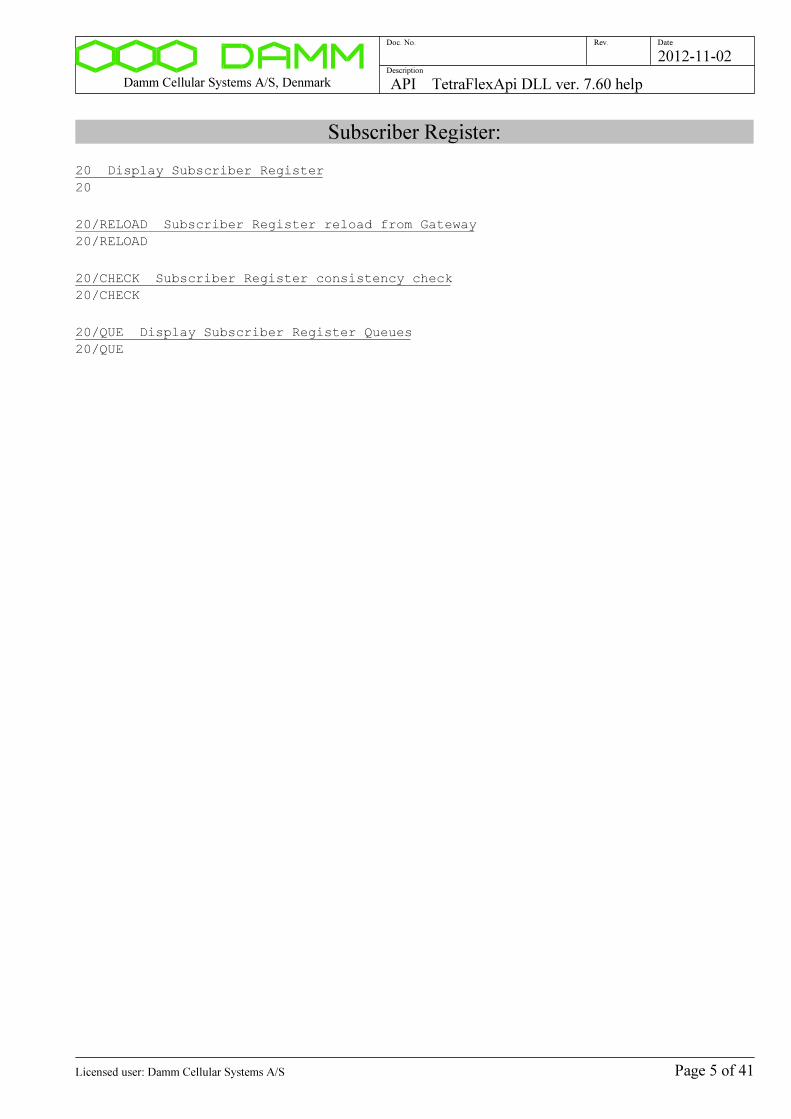
Damm Cellular Systems A/S, Denmark API TetraFlexApi DLL ver. 7.60 help
Doc. No. Rev. Date
Description
2012-11-02
Subscriber Register:
20 Display Subscriber Register
20
20/RELOAD Subscriber Register reload from Gateway
20/RELOAD
20/CHECK Subscriber Register consistency check
20/CHECK
20/QUE Display Subscriber Register Queues
20/QUE
Page 5 of 41Licensed user: Damm Cellular Systems A/S
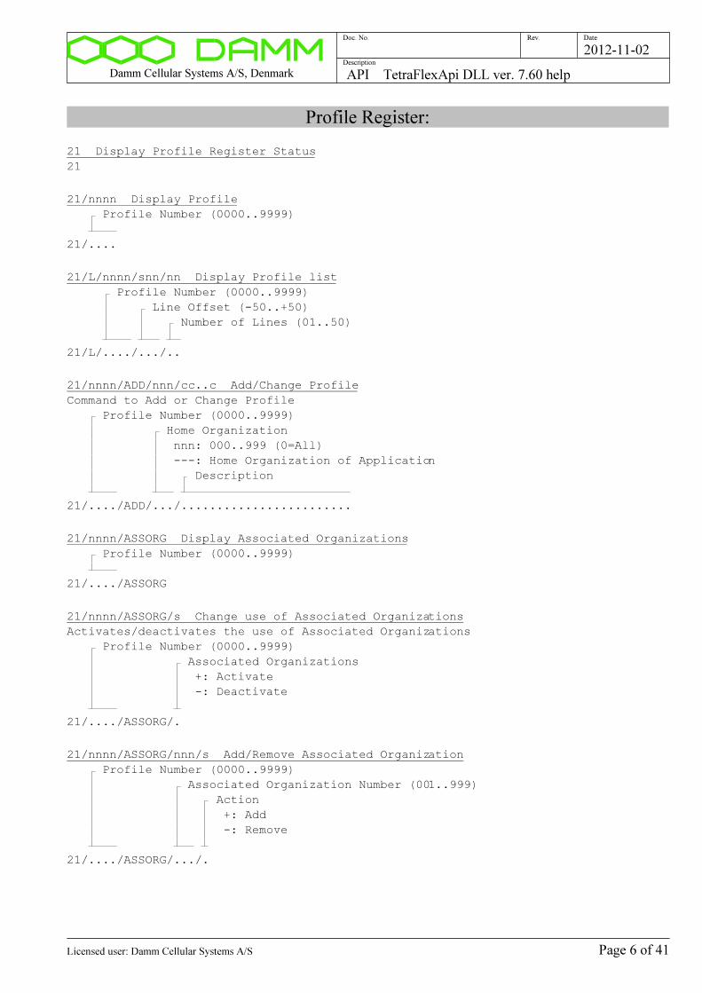
Damm Cellular Systems A/S, Denmark API TetraFlexApi DLL ver. 7.60 help
Doc. No. Rev. Date
Description
2012-11-02
Profile Register:
21 Display Profile Register Status
21
21/nnnn Display Profile
Profile Number (0000..9999)
21/....
21/L/nnnn/snn/nn Display Profile list
Profile Number (0000..9999)
Line Offset (-50..+50)
Number of Lines (01..50)
21/L/..../.../..
21/nnnn/ADD/nnn/cc..c Add/Change Profile
Command to Add or Change Profile
Profile Number (0000..9999)
Home Organization
nnn: 000..999 (0=All)
---: Home Organization of Application
Description
21/..../ADD/.../........................
21/nnnn/ASSORG Display Associated Organizations
Profile Number (0000..9999)
21/..../ASSORG
21/nnnn/ASSORG/s Change use of Associated Organizations
Activates/deactivates the use of Associated Organizations
Profile Number (0000..9999)
Associated Organizations
+: Activate
-: Deactivate
21/..../ASSORG/.
21/nnnn/ASSORG/nnn/s Add/Remove Associated Organization
Profile Number (0000..9999)
Associated Organization Number (001..999)
Action
+: Add
-: Remove
21/..../ASSORG/.../.
Page 6 of 41Licensed user: Damm Cellular Systems A/S

Damm Cellular Systems A/S, Denmark API TetraFlexApi DLL ver. 7.60 help
Doc. No. Rev. Date
Description
2012-11-02
21/nnnn/SSICALL/s Setup SSI Call Permission
Selects whether Individual Calls are allowed with SSI
If not selected, Individual Calls are only allowed wit User Number
Profile Number (0000..9999)
+: Allow Individual Calls with SSI
-: Only allow Individual Calls with User Number
21/..../SSICALL/.
21/nnnn/SSIGROUP/s Use SSI as Talking Party Identification for Group Calls
Selects the use of SSI as Talking Party Identification for Group Calls
to bypass the bug in certain mobiles (Motorola)
NB: This flag affects only GSSI's attached to the Profile (not ISSI)
Profile Number (0000..9999)
+: Use SSI as TPI for Group Call
-: Use User Number as TPI for Group Call (default)
21/..../SSIGROUP/.
21/nnnn/SECMODE/n Setup Security Mode
For optional modes, service will be allowed without Authentication/Air
InterFace encryption, when no Security Set is available or when the SSI
Authentication and Air Interface Encryption disable flags are set.
For mandatory modes, service will only be permitted with full Authentication
and Air Interface Encryption.
Note, that Air Interface Encryption requires, that permission is activated
in the License Dongle.
Profile Number (0000..9999)
Mode:
0: Class 1, no Auth./AIE
1: Class 1, Auth. optional, AIE none
2: Class 1, Auth. mandatory, AIE none
3: Class 3, Aut. optional, AIE optional
4: Class 3, Auth. mandatory, AIE mandatory
21/..../SECMODE/.
21/nnnn/SECKSG/nn Setup Key Stream Generator
Used with Air Interface Encryption only
Note, that the TR shall support the selected KSG.
Profile Number (0000..9999)
KSG:
00: TEA1
01: TEA2
02: TEA3
03: TEA4
04..15: Reserved
21/..../SECKSG/..
Page 7 of 41Licensed user: Damm Cellular Systems A/S
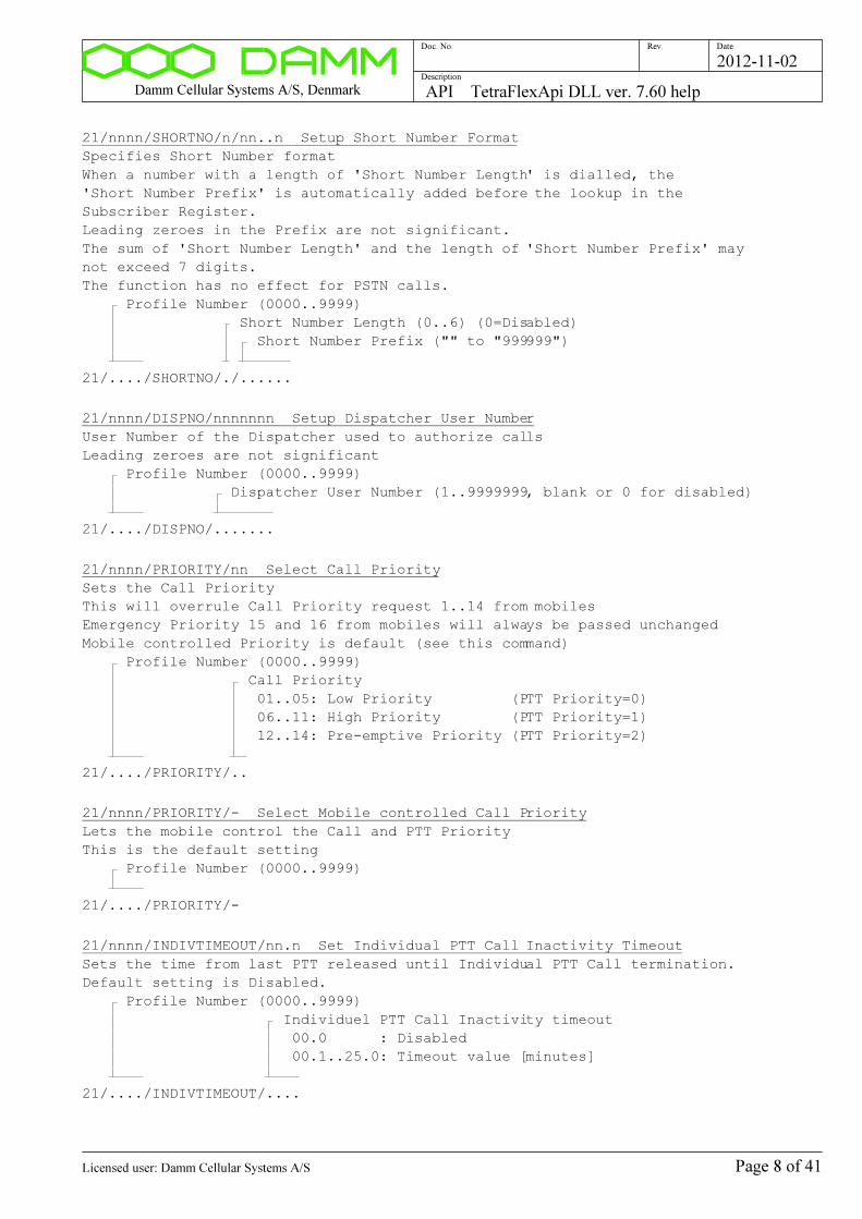
Damm Cellular Systems A/S, Denmark API TetraFlexApi DLL ver. 7.60 help
Doc. No. Rev. Date
Description
2012-11-02
21/nnnn/SHORTNO/n/nn..n Setup Short Number Format
Specifies Short Number format
When a number with a length of 'Short Number Length' is dialled, the
'Short Number Prefix' is automatically added before the lookup in the
Subscriber Register.
Leading zeroes in the Prefix are not significant.
The sum of 'Short Number Length' and the length of 'Short Number Prefix' may
not exceed 7 digits.
The function has no effect for PSTN calls.
Profile Number (0000..9999)
Short Number Length (0..6) (0=Disabled)
Short Number Prefix ("" to "999999")
21/..../SHORTNO/./......
21/nnnn/DISPNO/nnnnnnn Setup Dispatcher User Number
User Number of the Dispatcher used to authorize calls
Leading zeroes are not significant
Profile Number (0000..9999)
Dispatcher User Number (1..9999999, blank or 0 for disabled)
21/..../DISPNO/.......
21/nnnn/PRIORITY/nn Select Call Priority
Sets the Call Priority
This will overrule Call Priority request 1..14 from mobiles
Emergency Priority 15 and 16 from mobiles will always be passed unchanged
Mobile controlled Priority is default (see this command)
Profile Number (0000..9999)
Call Priority
01..05: Low Priority (PTT Priority=0)
06..11: High Priority (PTT Priority=1)
12..14: Pre-emptive Priority (PTT Priority=2)
21/..../PRIORITY/..
21/nnnn/PRIORITY/- Select Mobile controlled Call Priority
Lets the mobile control the Call and PTT Priority
This is the default setting
Profile Number (0000..9999)
21/..../PRIORITY/-
21/nnnn/INDIVTIMEOUT/nn.n Set Individual PTT Call Inactivity Timeout
Sets the time from last PTT released until Individual PTT Call termination.
Default setting is Disabled.
Profile Number (0000..9999)
Individuel PTT Call Inactivity timeout
00.0 : Disabled
00.1..25.0: Timeout value [minutes]
21/..../INDIVTIMEOUT/....
Page 8 of 41Licensed user: Damm Cellular Systems A/S

Damm Cellular Systems A/S, Denmark API TetraFlexApi DLL ver. 7.60 help
Doc. No. Rev. Date
Description
2012-11-02
21/nnnn/INDIVTIMEOUT/- Disable Individual PTT Call Inactivity Timeout
Disables timeout of Individual PTT Call.
This is the default setting.
Profile Number (0000..9999)
21/..../INDIVTIMEOUT/-
21/nnnn/GROUPTIMEOUT/nn Set Group Call Inactivity Timeout
Changes the time from last PTT is released until the group call
is terminated. Default value is 5 seconds.
Profile Number (0000..9999)
Group Call Inactivity timeout (00..20 seconds)
21/..../GROUPTIMEOUT/..
21/nnnn/CALLDURMAX/nnn Set max. Call Duration
Sets the maximum call duration of Individual Calls.
The default value is infinity (see this command)
Profile Number (0000..9999)
Max Call Duration (001..250 minutes)
21/..../CALLDURMAX/...
21/nnnn/CALLDURMAX/- Set Call Duration limit to infinity
Sets the maximum call duration of Individual Calls to infinity.
This is the default setting
Profile Number (0000..9999)
21/..../CALLDURMAX/-
21/nnnn/PTTDURMAX/nnn Set max. PTT Duration
Sets the maximun talking period at Simplex Calls
The default value is disabled (Mobile controlled) (see this command)
Profile Number (0000..9999)
Max PTT Duration (002..250 seconds)
21/..../PTTDURMAX/...
21/nnnn/PTTDURMAX/- Disable PTT Duration limit
Sets the maximun talking period at Simplex Calls to be controlled
of the Mobile.
The system will still limit the time to maximum 310 seconds,
which is longer than the maximum 300 second setting for the mobile.
This is the default setting.
Profile Number (0000..9999)
21/..../PTTDURMAX/-
Page 9 of 41Licensed user: Damm Cellular Systems A/S
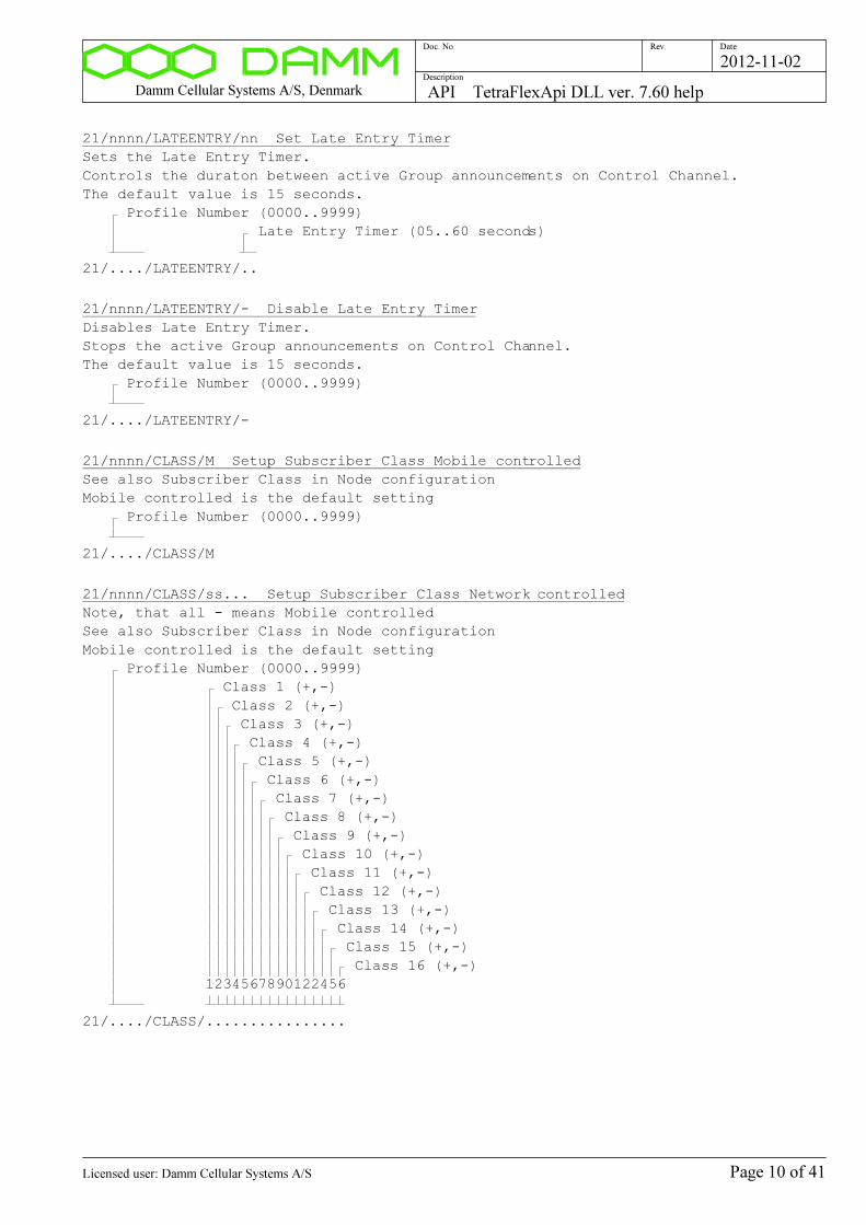
Damm Cellular Systems A/S, Denmark API TetraFlexApi DLL ver. 7.60 help
Doc. No. Rev. Date
Description
2012-11-02
21/nnnn/LATEENTRY/nn Set Late Entry Timer
Sets the Late Entry Timer.
Controls the duraton between active Group announcements on Control Channel.
The default value is 15 seconds.
Profile Number (0000..9999)
Late Entry Timer (05..60 seconds)
21/..../LATEENTRY/..
21/nnnn/LATEENTRY/- Disable Late Entry Timer
Disables Late Entry Timer.
Stops the active Group announcements on Control Channel.
The default value is 15 seconds.
Profile Number (0000..9999)
21/..../LATEENTRY/-
21/nnnn/CLASS/M Setup Subscriber Class Mobile controlled
See also Subscriber Class in Node configuration
Mobile controlled is the default setting
Profile Number (0000..9999)
21/..../CLASS/M
21/nnnn/CLASS/ss... Setup Subscriber Class Network controlled
Note, that all - means Mobile controlled
See also Subscriber Class in Node configuration
Mobile controlled is the default setting
Profile Number (0000..9999)
Class 1 (+,-)
Class 2 (+,-)
Class 3 (+,-)
Class 4 (+,-)
Class 5 (+,-)
Class 6 (+,-)
Class 7 (+,-)
Class 8 (+,-)
Class 9 (+,-)
Class 10 (+,-)
Class 11 (+,-)
Class 12 (+,-)
Class 13 (+,-)
Class 14 (+,-)
Class 15 (+,-)
Class 16 (+,-)
1234567890122456
21/..../CLASS/................
Page 10 of 41Licensed user: Damm Cellular Systems A/S

Damm Cellular Systems A/S, Denmark API TetraFlexApi DLL ver. 7.60 help
Doc. No. Rev. Date
Description
2012-11-02
21/nnnn/SERVRESTR Display SSI Service Restrictions
Profile Number (0000..9999)
21/..../SERVRESTR
21/nnnn/SERVRESTR/s Change SSI Service Restriction activation
Selects activation/deactivation of all SSI Service Restrictions
Profile Number (0000..9999)
+: Restrictions active according to individual flags
-: All Restrictions disabled (default)
21/..../SERVRESTR/.
21/nnnn/SERVPERM/c Display Service Permission flags
Profile Number (0000..9999)
SSI Kind
M: Mobile SSI
D: Dial-In SSI
A: Application SSI
T: Terminal SSI
21/..../SERVPERM/.
21/nnnn/SERVPERM/M/nn/c Change Mobile SSI Service Permission flag
NB: Common Service Restrictions shall be activated for individual flags to be
significant.
Profile Number (0000..9999)
Mobile SSI Permission Flag Number (00..15)
00: Individual Duplex Call to Mobile
01: Individual Duplex Call from Mobile
02: Individual Simplex Call to Mobile
03: Individual Simplex Call from Mobile
04: Individual Call to Voice Gateway
05: Individual Call from Voice Gateway
06: Individual Call to Application Gateway
07: Individual Call from Application Gateway
08: Group Call
09: Send SDS
10: Receive Individual SDS
11: Packet Data Call
Flag
+: Service allowed
A: Service allowed with Dispatcher Authorization
(00..07 only)
-: Service not allowed
21/..../SERVPERM/M/../.
Page 11 of 41Licensed user: Damm Cellular Systems A/S
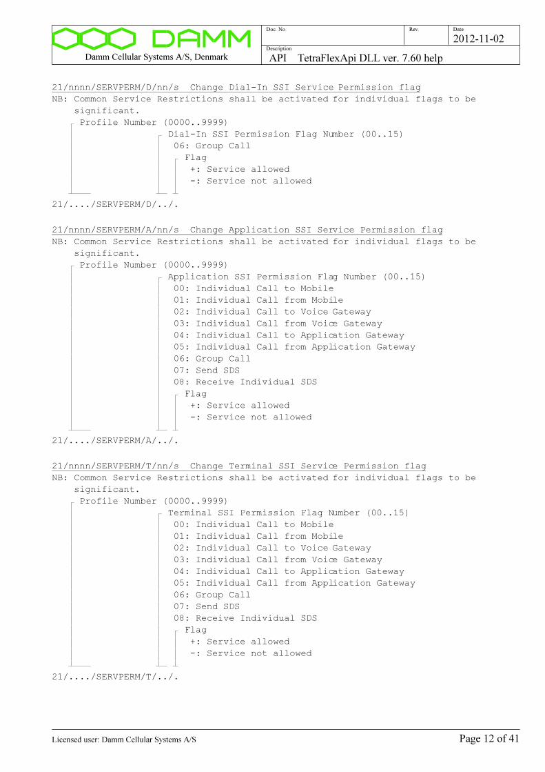
Damm Cellular Systems A/S, Denmark API TetraFlexApi DLL ver. 7.60 help
Doc. No. Rev. Date
Description
2012-11-02
21/nnnn/SERVPERM/D/nn/s Change Dial-In SSI Service Permission flag
NB: Common Service Restrictions shall be activated for individual flags to be
significant.
Profile Number (0000..9999)
Dial-In SSI Permission Flag Number (00..15)
06: Group Call
Flag
+: Service allowed
-: Service not allowed
21/..../SERVPERM/D/../.
21/nnnn/SERVPERM/A/nn/s Change Application SSI Service Permission flag
NB: Common Service Restrictions shall be activated for individual flags to be
significant.
Profile Number (0000..9999)
Application SSI Permission Flag Number (00..15)
00: Individual Call to Mobile
01: Individual Call from Mobile
02: Individual Call to Voice Gateway
03: Individual Call from Voice Gateway
04: Individual Call to Application Gateway
05: Individual Call from Application Gateway
06: Group Call
07: Send SDS
08: Receive Individual SDS
Flag
+: Service allowed
-: Service not allowed
21/..../SERVPERM/A/../.
21/nnnn/SERVPERM/T/nn/s Change Terminal SSI Service Permission flag
NB: Common Service Restrictions shall be activated for individual flags to be
significant.
Profile Number (0000..9999)
Terminal SSI Permission Flag Number (00..15)
00: Individual Call to Mobile
01: Individual Call from Mobile
02: Individual Call to Voice Gateway
03: Individual Call from Voice Gateway
04: Individual Call to Application Gateway
05: Individual Call from Application Gateway
06: Group Call
07: Send SDS
08: Receive Individual SDS
Flag
+: Service allowed
-: Service not allowed
21/..../SERVPERM/T/../.
Page 12 of 41Licensed user: Damm Cellular Systems A/S

Damm Cellular Systems A/S, Denmark API TetraFlexApi DLL ver. 7.60 help
Doc. No. Rev. Date
Description
2012-11-02
21/nnnn/SERVPERM/M/cc..c Change all Mobile SSI Service Permission flags
NB: Common Service Restrictions shall be activated for individual flags to be
significant.
Profile Number (0000..9999)
Mobile SSI Service Permission Flags:
+: Service allowed
A: Service allowed with Dispatcher Authorization (00..07
only)
-: Service not allowed
00: Individual Duplex Call to Mobile
01: Individual Duplex Call from Mobile
02: Individual Simplex Call to Mobile
03: Individual Simplex Call from Mobile
04: Individual Call to Voice Gateway
05: Individual Call from Voice Gateway
06: Individual Call to Application Gateway
07: Individual Call from Application Gateway
08: Group Call
09: Send SDS
10: Receive Individual SDS
11: Packet Data Call
12: (Spare)
13: (Spare)
14: (Spare)
15: (Spare)
21/..../SERVPERM/M/................
21/nnnn/SERVPERM/D/ss..s Change all Dial-In SSI Service Permission flags
NB: Common Service Restrictions shall be activated for individual flags to be
significant.
Profile Number (0000..9999)
Dial-In SSI Service Permission Flags:
+: Service allowed
-: Service not allowed
00: (Spare)
01: (Spare)
02: (Spare)
03: (Spare)
04: (Spare)
05: (Spare)
06: Group Call
07: (Spare)
08: (Spare)
09: (Spare)
10: (Spare)
11: (Spare)
12: (Spare)
13: (Spare)
14: (Spare)
15: (Spare)
21/..../SERVPERM/D/................
Page 13 of 41Licensed user: Damm Cellular Systems A/S
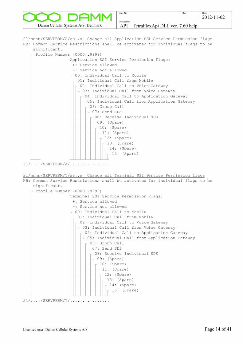
Damm Cellular Systems A/S, Denmark API TetraFlexApi DLL ver. 7.60 help
Doc. No. Rev. Date
Description
2012-11-02
21/nnnn/SERVPERM/A/ss..s Change all Application SSI Service Permission flags
NB: Common Service Restrictions shall be activated for individual flags to be
significant.
Profile Number (0000..9999)
Application SSI Service Permission Flags:
+: Service allowed
-: Service not allowed
00: Individual Call to Mobile
01: Individual Call from Mobile
02: Individual Call to Voice Gateway
03: Individual Call from Voice Gateway
04: Individual Call to Application Gateway
05: Individual Call from Application Gateway
06: Group Call
07: Send SDS
08: Receive Individual SDS
09: (Spare)
10: (Spare)
11: (Spare)
12: (Spare)
13: (Spare)
14: (Spare)
15: (Spare)
21/..../SERVPERM/A/................
21/nnnn/SERVPERM/T/ss..s Change all Terminal SSI Service Permission flags
NB: Common Service Restrictions shall be activated for individual flags to be
significant.
Profile Number (0000..9999)
Terminal SSI Service Permission Flags:
+: Service allowed
-: Service not allowed
00: Individual Call to Mobile
01: Individual Call from Mobile
02: Individual Call to Voice Gateway
03: Individual Call from Voice Gateway
04: Individual Call to Application Gateway
05: Individual Call from Application Gateway
06: Group Call
07: Send SDS
08: Receive Individual SDS
09: (Spare)
10: (Spare)
11: (Spare)
12: (Spare)
13: (Spare)
14: (Spare)
15: (Spare)
21/..../SERVPERM/T/................
Page 14 of 41Licensed user: Damm Cellular Systems A/S
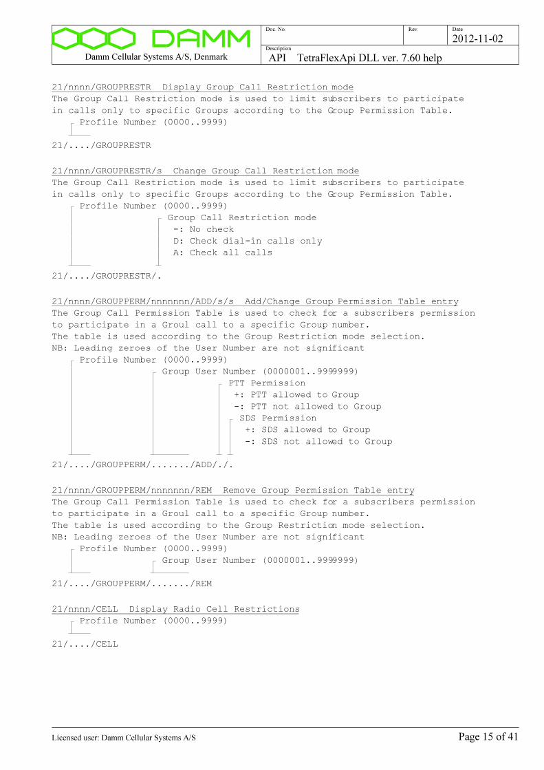
Damm Cellular Systems A/S, Denmark API TetraFlexApi DLL ver. 7.60 help
Doc. No. Rev. Date
Description
2012-11-02
21/nnnn/GROUPRESTR Display Group Call Restriction mode
The Group Call Restriction mode is used to limit subscribers to participate
in calls only to specific Groups according to the Group Permission Table.
Profile Number (0000..9999)
21/..../GROUPRESTR
21/nnnn/GROUPRESTR/s Change Group Call Restriction mode
The Group Call Restriction mode is used to limit subscribers to participate
in calls only to specific Groups according to the Group Permission Table.
Profile Number (0000..9999)
Group Call Restriction mode
-: No check
D: Check dial-in calls only
A: Check all calls
21/..../GROUPRESTR/.
21/nnnn/GROUPPERM/nnnnnnn/ADD/s/s Add/Change Group Permission Table entry
The Group Call Permission Table is used to check for a subscribers permission
to participate in a Groul call to a specific Group number.
The table is used according to the Group Restriction mode selection.
NB: Leading zeroes of the User Number are not significant
Profile Number (0000..9999)
Group User Number (0000001..9999999)
PTT Permission
+: PTT allowed to Group
-: PTT not allowed to Group
SDS Permission
+: SDS allowed to Group
-: SDS not allowed to Group
21/..../GROUPPERM/......./ADD/./.
21/nnnn/GROUPPERM/nnnnnnn/REM Remove Group Permission Table entry
The Group Call Permission Table is used to check for a subscribers permission
to participate in a Groul call to a specific Group number.
The table is used according to the Group Restriction mode selection.
NB: Leading zeroes of the User Number are not significant
Profile Number (0000..9999)
Group User Number (0000001..9999999)
21/..../GROUPPERM/......./REM
21/nnnn/CELL Display Radio Cell Restrictions
Profile Number (0000..9999)
21/..../CELL
Page 15 of 41Licensed user: Damm Cellular Systems A/S
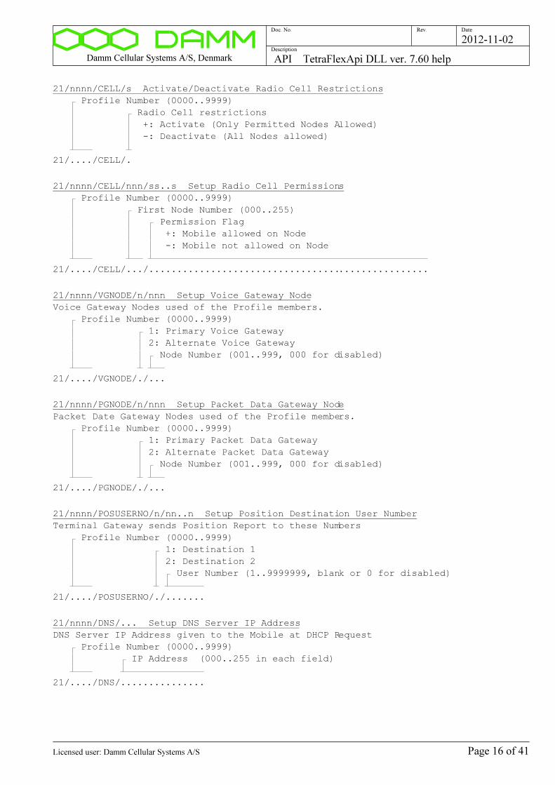
Damm Cellular Systems A/S, Denmark API TetraFlexApi DLL ver. 7.60 help
Doc. No. Rev. Date
Description
2012-11-02
21/nnnn/CELL/s Activate/Deactivate Radio Cell Restrictions
Profile Number (0000..9999)
Radio Cell restrictions
+: Activate (Only Permitted Nodes Allowed)
-: Deactivate (All Nodes allowed)
21/..../CELL/.
21/nnnn/CELL/nnn/ss..s Setup Radio Cell Permissions
Profile Number (0000..9999)
First Node Number (000..255)
Permission Flag
+: Mobile allowed on Node
-: Mobile not allowed on Node
21/..../CELL/.../..................................................
21/nnnn/VGNODE/n/nnn Setup Voice Gateway Node
Voice Gateway Nodes used of the Profile members.
Profile Number (0000..9999)
1: Primary Voice Gateway
2: Alternate Voice Gateway
Node Number (001..999, 000 for disabled)
21/..../VGNODE/./...
21/nnnn/PGNODE/n/nnn Setup Packet Data Gateway Node
Packet Date Gateway Nodes used of the Profile members.
Profile Number (0000..9999)
1: Primary Packet Data Gateway
2: Alternate Packet Data Gateway
Node Number (001..999, 000 for disabled)
21/..../PGNODE/./...
21/nnnn/POSUSERNO/n/nn..n Setup Position Destination User Number
Terminal Gateway sends Position Report to these Numbers
Profile Number (0000..9999)
1: Destination 1
2: Destination 2
User Number (1..9999999, blank or 0 for disabled)
21/..../POSUSERNO/./.......
21/nnnn/DNS/... Setup DNS Server IP Address
DNS Server IP Address given to the Mobile at DHCP Request
Profile Number (0000..9999)
IP Address (000..255 in each field)
21/..../DNS/...............
Page 16 of 41Licensed user: Damm Cellular Systems A/S
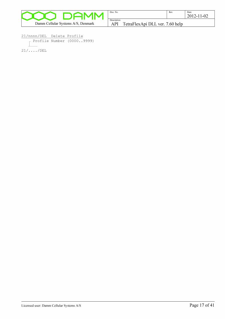
Damm Cellular Systems A/S, Denmark API TetraFlexApi DLL ver. 7.60 help
Doc. No. Rev. Date
Description
2012-11-02
21/nnnn/DEL Delete Profile
Profile Number (0000..9999)
21/..../DEL
Page 17 of 41Licensed user: Damm Cellular Systems A/S
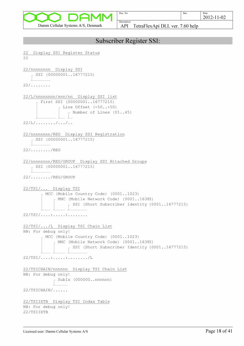
Damm Cellular Systems A/S, Denmark API TetraFlexApi DLL ver. 7.60 help
Doc. No. Rev. Date
Description
2012-11-02
Subscriber Register SSI:
22 Display SSI Register Status
22
22/nnnnnnnn Display SSI
SSI (00000001..16777215)
22/........
22/L/nnnnnnnn/snn/nn Display SSI list
First SSI (00000001..16777215)
Line Offset (-50..+50)
Number of Lines (01..45)
22/L/......../.../..
22/nnnnnnnn/REG Display SSI Registration
SSI (00000001..16777215)
22/......../REG
22/nnnnnnnn/REG/GROUP Display SSI Attached Groups
SSI (00000001..16777215)
22/......../REG/GROUP
22/TSI/... Display TSI
MCC (Mobile Country Code) (0001..1023)
MNC (Mobile Network Code) (0001..16383)
SSI (Short Subscriber Identity (0001..16777215)
22/TSI/....:.....:........
22/TSI/.../L Display TSI Chain List
NB: For debug only!
MCC (Mobile Country Code) (0001..1023)
MNC (Mobile Network Code) (0001..16383)
SSI (Short Subscriber Identity (0001..16777215)
22/TSI/....:.....:......../L
22/TSICHAIN/nnnnnn Display TSI Chain List
NB: For debug only!
SubIx (000000..nnnnnn)
22/TSICHAIN/......
22/TSIIXTB Display TSI Indax Table
NB: For debug only!
22/TSIIXTB
Page 18 of 41Licensed user: Damm Cellular Systems A/S
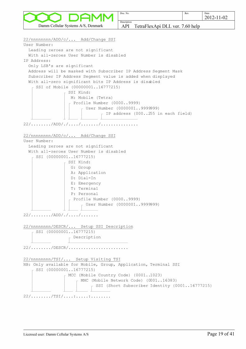
Damm Cellular Systems A/S, Denmark API TetraFlexApi DLL ver. 7.60 help
Doc. No. Rev. Date
Description
2012-11-02
22/nnnnnnnn/ADD/c/... Add/Change SSI
User Number:
Leading zeroes are not significant
With all-zeroes User Number is disabled
IP Address:
Only LSB's are significant
Address will be masked with Subscriber IP Address Segment Mask
Subscriber IP Address Segment value is added when displayed
With all-zero significant bits IP Address is disabled
SSI of Mobile (00000001..16777215)
SSI Kind:
M: Mobile (Tetra)
Profile Number (0000..9999)
User Number (0000001..9999999)
IP address (000..255 in each field)
22/......../ADD/./..../......./...............
22/nnnnnnnn/ADD/c/... Add/Change SSI
User Number:
Leading zeroes are not significant
With all-zeroes User Number is disabled
SSI (00000001..16777215)
SSI Kind:
G: Group
A: Application
D: Dial-In
E: Emergency
T: Terminal
P: Personal
Profile Number (0000..9999)
User Number (0000001..9999999)
22/......../ADD/./..../.......
22/nnnnnnnn/DESCR/... Setup SSI Description
SSI (00000001..16777215)
Description
22/......../DESCR/........................
22/nnnnnnnn/TSI/... Setup Visiting TSI
NB: Only available for Mobile, Group, Application, Terminal SSI
SSI (00000001..16777215)
MCC (Mobile Country Code) (0001..1023)
MNC (Mobile Network Code) (0001..16383)
SSI (Short Subscriber Identity (0001..16777215)
22/......../TSI/....:.....:........
Page 19 of 41Licensed user: Damm Cellular Systems A/S

Damm Cellular Systems A/S, Denmark API TetraFlexApi DLL ver. 7.60 help
Doc. No. Rev. Date
Description
2012-11-02
22/nnnnnnnn/TSI/- Clear Visiting TSI
SSI (00000001..16777215)
22/......../TSI/-
22/nnnnnnnn/BLOCK/s Change SSI Blocking
SSI (00000001..16777215)
+: SSI Block
-: SSI Unblock
22/......../BLOCK/.
22/nnnnnnnn/PINCODE/cc..c Change PIN Code
PIN Code 1..9 digits, leading zeroes not significant
NB: Only available for DialIn, Application and Terminal SSI
SSI (00000001..16777215)
PIN Code:
1..999999999: Value
-: Disabled
22/......../PINCODE/.........
22/nnnnnnnn/TEI/... Setup TEI Terminal Equipment Identity
NB: Only available for Mobile, Application, Terminal SSI
SSI (00000001..16777215)
TEI (15 hex digits 0..9 or A..F)
22/......../TEI/...............
22/nnnnnnnn/TEI/- Clear TEI Terminal Equipment Identity
NB: Only available for Mobile, Application, Terminal SSI
SSI (00000001..16777215)
22/......../TEI/-
22/nnnnnnnn/SIM/... Setup SIM ID
ID of SIM Card if present
Shall be cleared if not used
If SIM ID is setup, SIM ID is used to find K in Key Register,
else TEI is used.
NB: Only available for Mobile, Application, Terminal SSI
SSI (00000001..16777215)
SIM ID (20 hex digits 0..9 or A..F)
22/......../SIM/....................
22/nnnnnnnn/SIM/- Clear SIM ID
NB: Only available for Mobile, Application, Terminal SSI
SSI (00000001..16777215)
22/......../SIM/-
Page 20 of 41Licensed user: Damm Cellular Systems A/S

Damm Cellular Systems A/S, Denmark API TetraFlexApi DLL ver. 7.60 help
Doc. No. Rev. Date
Description
2012-11-02
22/nnnnnnnn/AUTHDIS/s Change Mobile Authentication Disable Flag
Note, that Authentication disable is not possible in mandatory
modes selected in the Profile register.
NB: Only available for Mobile, Application and Terminal SSI
SSI (00000001..16777215)
Authentication Disable Flag
+: Disable Authentication
-: Authentication not disabled
22/......../AUTHDIS/.
22/nnnnnnnn/AIEDIS/s Change Air Interface Encryption Disable Flag
Note, that Air Interface Encryption disable is not possible in mandatory
mode selected in the Profile register.
NB: Only available for Mobile, Group SSI
SSI (00000001..16777215)
Air Interface Encryption Disable Flag
+: Disable Air Interface Encryption
-: Air Interface Encryption not disabled
22/......../AIEDIS/.
22/nnnnnnnn/SECSET/R Renew Security Set from Security Key
The Security Key will be search with the following references:
1) If SIM is setup, SIM will be used for Key search
2) Else if TEI is setup, TEI will be used for Key search
3) Else no renewal is done
NB: Only available for Mobile, Application, Terminal SSI
SSI (00000001..16777215)
22/......../SECSET/R
22/nnnnnnnn/SECSET/... Setup Security Set
This command is for manual test only
Security set update should normally be done from Security Key
NB: Only available for Mobile, Application, Terminal SSI
SSI (00000001..16777215)
Status
U: Unencrypted
E: Encrypted
RS (20 hex digits)
KS (32 hex digits)
KS' (32 hex digits)
9 8 7 6 5 4 3 2 1 0 5 4 3 2 1 0 9 8 7 6 5 4 3 2 1 0 5 4
3 2 1 0 9 8 7 6 5 4 3 2 1 0
ÿ ¿ ¿ ¿ ¿ ¿ ¿ ¿ ¿ ¿ ÿ ¿ ¿ ¿ ¿ ¿ ¿ ¿ ¿ ¿ ¿ ¿ ¿ ¿ ¿ ¿
ÿ ¿ ¿ ¿ ¿ ¿ ¿ ¿ ¿ ¿ ¿ ¿ ¿ ¿ ¿ ¿
22/......../SECSET/./..................../................................/....
............................
Page 21 of 41Licensed user: Damm Cellular Systems A/S
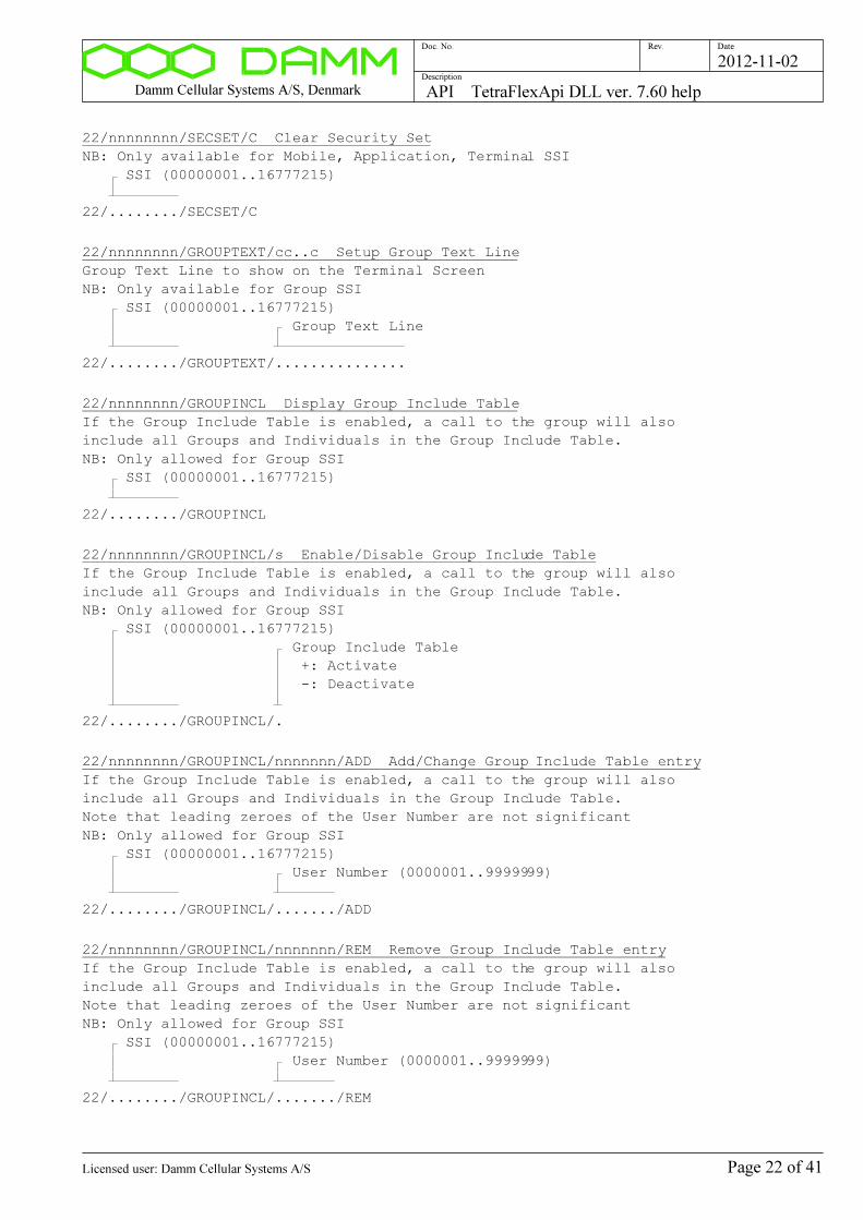
Damm Cellular Systems A/S, Denmark API TetraFlexApi DLL ver. 7.60 help
Doc. No. Rev. Date
Description
2012-11-02
22/nnnnnnnn/SECSET/C Clear Security Set
NB: Only available for Mobile, Application, Terminal SSI
SSI (00000001..16777215)
22/......../SECSET/C
22/nnnnnnnn/GROUPTEXT/cc..c Setup Group Text Line
Group Text Line to show on the Terminal Screen
NB: Only available for Group SSI
SSI (00000001..16777215)
Group Text Line
22/......../GROUPTEXT/...............
22/nnnnnnnn/GROUPINCL Display Group Include Table
If the Group Include Table is enabled, a call to the group will also
include all Groups and Individuals in the Group Include Table.
NB: Only allowed for Group SSI
SSI (00000001..16777215)
22/......../GROUPINCL
22/nnnnnnnn/GROUPINCL/s Enable/Disable Group Include Table
If the Group Include Table is enabled, a call to the group will also
include all Groups and Individuals in the Group Include Table.
NB: Only allowed for Group SSI
SSI (00000001..16777215)
Group Include Table
+: Activate
-: Deactivate
22/......../GROUPINCL/.
22/nnnnnnnn/GROUPINCL/nnnnnnn/ADD Add/Change Group Include Table entry
If the Group Include Table is enabled, a call to the group will also
include all Groups and Individuals in the Group Include Table.
Note that leading zeroes of the User Number are not significant
NB: Only allowed for Group SSI
SSI (00000001..16777215)
User Number (0000001..9999999)
22/......../GROUPINCL/......./ADD
22/nnnnnnnn/GROUPINCL/nnnnnnn/REM Remove Group Include Table entry
If the Group Include Table is enabled, a call to the group will also
include all Groups and Individuals in the Group Include Table.
Note that leading zeroes of the User Number are not significant
NB: Only allowed for Group SSI
SSI (00000001..16777215)
User Number (0000001..9999999)
22/......../GROUPINCL/......./REM
Page 22 of 41Licensed user: Damm Cellular Systems A/S
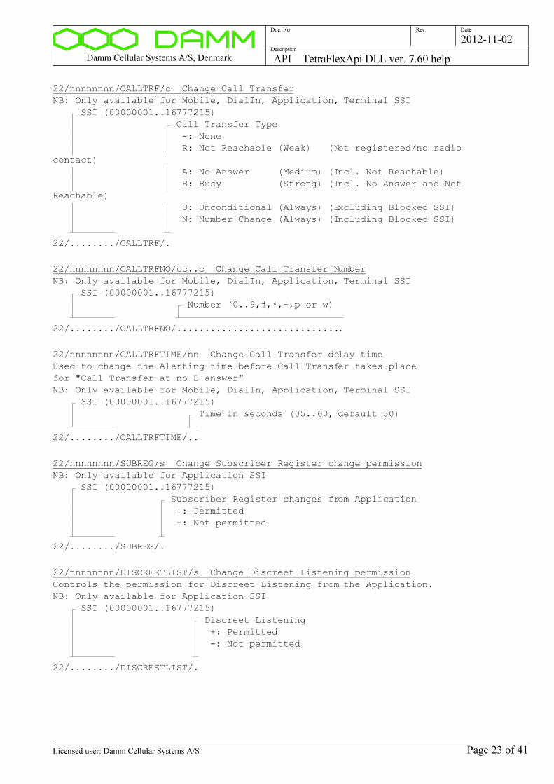
Damm Cellular Systems A/S, Denmark API TetraFlexApi DLL ver. 7.60 help
Doc. No. Rev. Date
Description
2012-11-02
22/nnnnnnnn/CALLTRF/c Change Call Transfer
NB: Only available for Mobile, DialIn, Application, Terminal SSI
SSI (00000001..16777215)
Call Transfer Type
-: None
R: Not Reachable (Weak) (Not registered/no radio
contact)
A: No Answer (Medium) (Incl. Not Reachable)
B: Busy (Strong) (Incl. No Answer and Not
Reachable)
U: Unconditional (Always) (Excluding Blocked SSI)
N: Number Change (Always) (Including Blocked SSI)
22/......../CALLTRF/.
22/nnnnnnnn/CALLTRFNO/cc..c Change Call Transfer Number
NB: Only available for Mobile, DialIn, Application, Terminal SSI
SSI (00000001..16777215)
Number (0..9,#,*,+,p or w)
22/......../CALLTRFNO/..............................
22/nnnnnnnn/CALLTRFTIME/nn Change Call Transfer delay time
Used to change the Alerting time before Call Transfer takes place
for "Call Transfer at no B-answer"
NB: Only available for Mobile, DialIn, Application, Terminal SSI
SSI (00000001..16777215)
Time in seconds (05..60, default 30)
22/......../CALLTRFTIME/..
22/nnnnnnnn/SUBREG/s Change Subscriber Register change permission
NB: Only available for Application SSI
SSI (00000001..16777215)
Subscriber Register changes from Application
+: Permitted
-: Not permitted
22/......../SUBREG/.
22/nnnnnnnn/DISCREETLIST/s Change Discreet Listening permission
Controls the permission for Discreet Listening from the Application.
NB: Only available for Application SSI
SSI (00000001..16777215)
Discreet Listening
+: Permitted
-: Not permitted
22/......../DISCREETLIST/.
Page 23 of 41Licensed user: Damm Cellular Systems A/S
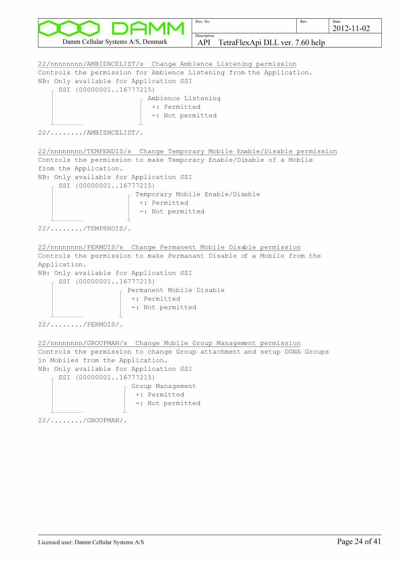
Damm Cellular Systems A/S, Denmark API TetraFlexApi DLL ver. 7.60 help
Doc. No. Rev. Date
Description
2012-11-02
22/nnnnnnnn/AMBIENCELIST/s Change Ambience Listening permission
Controls the permission for Ambience Listening from the Application.
NB: Only available for Application SSI
SSI (00000001..16777215)
Ambience Listening
+: Permitted
-: Not permitted
22/......../AMBIENCELIST/.
22/nnnnnnnn/TEMPENDIS/s Change Temporary Mobile Enable/Disable permission
Controls the permission to make Temporary Enable/Disable of a Mobile
from the Application.
NB: Only available for Application SSI
SSI (00000001..16777215)
Temporary Mobile Enable/Disable
+: Permitted
-: Not permitted
22/......../TEMPENDIS/.
22/nnnnnnnn/PERMDIS/s Change Permanent Mobile Disable permission
Controls the permission to make Permanant Disable of a Mobile from the
Application.
NB: Only available for Application SSI
SSI (00000001..16777215)
Permanent Mobile Disable
+: Permitted
-: Not permitted
22/......../PERMDIS/.
22/nnnnnnnn/GROUPMAN/s Change Mobile Group Management permission
Controls the permission to change Group attachment and setup DGNA Groups
in Mobiles from the Application.
NB: Only available for Application SSI
SSI (00000001..16777215)
Group Management
+: Permitted
-: Not permitted
22/......../GROUPMAN/.
Page 24 of 41Licensed user: Damm Cellular Systems A/S
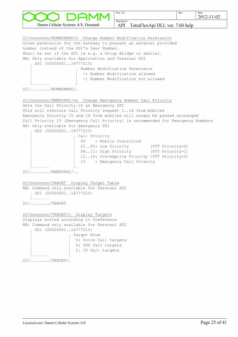
Damm Cellular Systems A/S, Denmark API TetraFlexApi DLL ver. 7.60 help
Doc. No. Rev. Date
Description
2012-11-02
22/nnnnnnnn/NUMBERMOD/s Change Number Modification Permission
Gives permission for the Gateway to present an external provided
number instead of the SSI's User Number.
Shall be set if the SSI is e.g. a Group Bridge or similar.
NB: Only available for Application and Terminal SSI
SSI (00000001..16777215)
Number Modification Permission
+: Number Modification allowed
-: Number Modification not allowed
22/......../NUMBERMOD/.
22/nnnnnnnn/EMERGPRI/nn Change Emergency Number Call Priority
Sets the Call Priority of an Emergency SSI
This will overrule Call Priority request 1..14 from mobiles
Emergency Priority 15 and 16 from mobiles will always be passed unchanged
Call Priority 15 (Emergency Call Priority) is recommended for Emergency Numbers
NB: Only available for Emergency SSI
SSI (00000001..16777215)
Call Priority
00 : Mobile Controlled
01..05: Low Priority (PTT Priority=0)
06..11: High Priority (PTT Priority=1)
12..14: Pre-emptive Priority (PTT Priority=2)
15 : Emergency Call Priority
22/......../EMERGPRI/..
22/nnnnnnnn/TARGET Display Target Table
NB: Command only available for Personal SSI
SSI (00000001..16777215)
22/......../TARGET
22/nnnnnnnn/TARGET/c Display Targets
Displays sorted according to Preference
NB: Command only available for Personal SSI
SSI (00000001..16777215)
Target Kind
V: Voice Call targets
S: SDS Call targets
I: IP Call targets
22/......../TARGET/.
Page 25 of 41Licensed user: Damm Cellular Systems A/S

Damm Cellular Systems A/S, Denmark API TetraFlexApi DLL ver. 7.60 help
Doc. No. Rev. Date
Description
2012-11-02
22/nnnnnnnn/TARGET/n/c/c/c/cc..c Add/Change/Remove Target
Add, Change or Remove a Target Number for the Personal SSI.
Targets with different Preferences will be accessed sequentially
starting with Preference 0.
Targets with same Preference will be accessed in parallel.
Voice Call:
Call will be through-connected to the Target making B-answer
SDS Call:
SDS will be send to all registered Targets.
IP Call:
IP connection will be done to first Targets with IP registation.
NB: Command only available for Personal SSI
SSI (00000001..16777215)
Target table position (0..7)
Voice Call Preference (1..8 or -)
SDS Call Preference (1..8 or -)
IP Call Preference (1..8 or -)
Target Number (Empty to remove)
22/......../TARGET/././././..............................
22/nnnnnnnn/DEL Delete SSI
SSI (00000001..16777215)
22/......../DEL
Page 26 of 41Licensed user: Damm Cellular Systems A/S

Damm Cellular Systems A/S, Denmark API TetraFlexApi DLL ver. 7.60 help
Doc. No. Rev. Date
Description
2012-11-02
Subscriber Register User Number:
23 Display SSI Register Status
23
23/nnnnnnn Display User Number
User Number (0000001..9999999)
23/.......
23/L/nnnnnnn/snn/nn Display User Number list
First User Number (0000001..9999999)
Line Offset (-50..+50)
Number of Lines (01..45)
23/L/......./.../..
Page 27 of 41Licensed user: Damm Cellular Systems A/S

Damm Cellular Systems A/S, Denmark API TetraFlexApi DLL ver. 7.60 help
Doc. No. Rev. Date
Description
2012-11-02
Subscriber Register IP Address:
24 Display SSI Register Status
24
24/nnn.nnn.nnn.nnnn Display IP Address
Only LSB's are significant
Address will be masked with Subscriber IP Address Segment Mask
Subscriber IP Address Segment value is added when displayed
IP Address (000..255 in each field)
24/...............
24/L/nnn.nnn.nnn.nnn/snn/nn Display IP Address list
First IP Address (000..255 in each field)
Line Offset (-50..+50)
Number of Lines (01..45)
24/L/.............../.../..
Page 28 of 41Licensed user: Damm Cellular Systems A/S
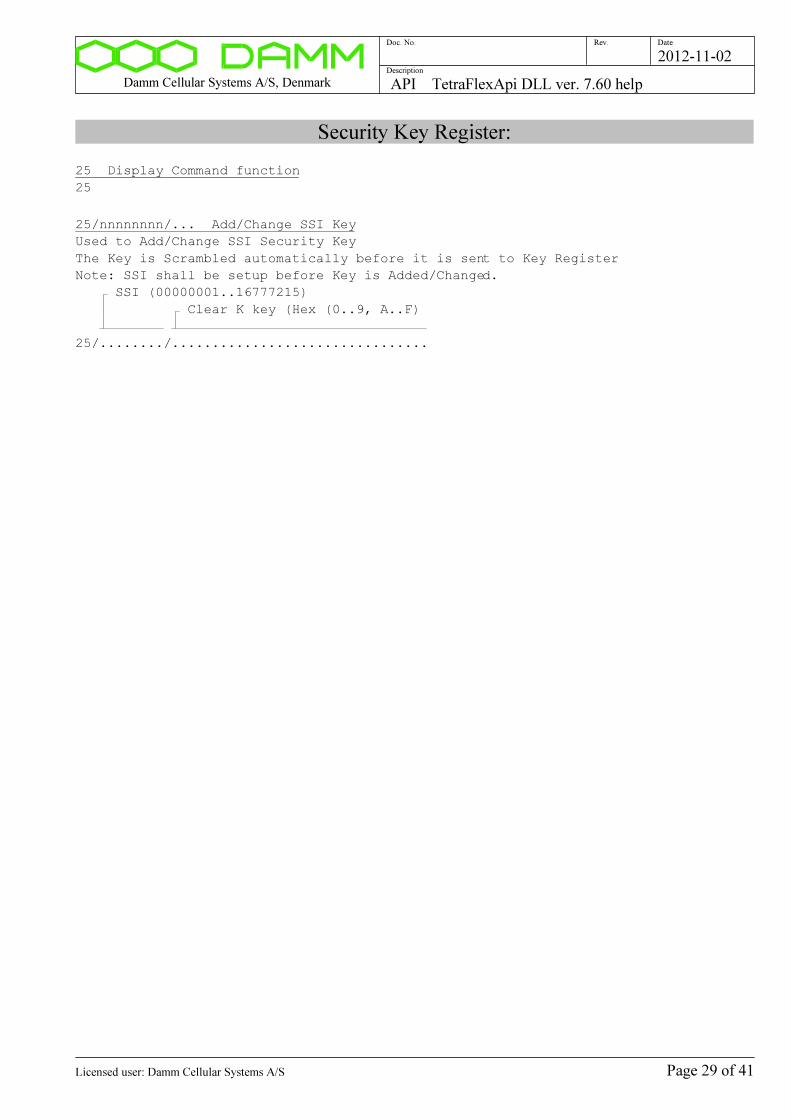
Damm Cellular Systems A/S, Denmark API TetraFlexApi DLL ver. 7.60 help
Doc. No. Rev. Date
Description
2012-11-02
Security Key Register:
25 Display Command function
25
25/nnnnnnnn/... Add/Change SSI Key
Used to Add/Change SSI Security Key
The Key is Scrambled automatically before it is sent to Key Register
Note: SSI shall be setup before Key is Added/Changed.
SSI (00000001..16777215)
Clear K key (Hex (0..9, A..F)
25/......../................................
Page 29 of 41Licensed user: Damm Cellular Systems A/S
Damm Cellular Systems A/S, Denmark API TetraFlexApi DLL ver. 7.60 help
Doc. No. Rev. Date
Description
2012-11-02
Organization Register:
26 Display Organization Register Status
26
26/nnnn Display Organization
Organization Number (000..999)
26/...
26/L/nnn/snn/nn Display Organization list
Organization Number (000..999)
Line Offset (-50..+50)
Number of Lines (01..50)
26/L/.../.../..
26/nnn/ADD/cc..c Add/Change Organization
NB: Command only allowed from Organization 000 Application
NB: All ranges automatically set to full range for Organization 000
Organization Number (000..999)
Description
26/.../ADD/........................
26/nnn/PROFNO/... Change Profile Number range
Limits the Profile Numbers, which can be added via an Application Gateway
Does not limit the range for an Organization 000 Application
NB: Command only allowed from Organization 000 Application
NB: Automatically set to full range for Organization 000
Organization Number (000..999)
Lowest permitted Profile Number (0000..9999)
Highest permitted Profile Number (0000..9999) (0=Barred)
26/.../PROFNO/..../....
26/nnn/SSI/... Change SSI range
Limits the SSIs, which can be added via an Application Gateway
Does not limit the range for an Organization 000 Application
NB: Command only allowed from Organization 000 Application
NB: Automatically set to full range for Organization 000
Organization Number (000..999)
Lowest permitted SSI (00000001..16777215)
Highest permitted SSI (00000001..16777215) (0=Barred)
26/.../SSI/......../........
Page 30 of 41Licensed user: Damm Cellular Systems A/S
Damm Cellular Systems A/S, Denmark API TetraFlexApi DLL ver. 7.60 help
Doc. No. Rev. Date
Description
2012-11-02
26/nnn/USERNO/... Change User Number range
Limits the User Numbers, which can be added via an Application Gateway
Does not limit the range for an Organization 000 Application
Leading zeroes in User Numbers are not significant
NB: Command only allowed from Organization 000 Application
NB: Automatically set to full range for Organization 000
Organization Number (000..999)
Lowest permitted User Number (0000001..9999999)
Highest permitted User Number (0000001..9999999)
(0=Barred)
26/.../USERNO/......./.......
26/nnn/IPADDR/... Change IP Address range
Limits the IP Addresses, which can be added via an Application Gateway
Does not limit the range for an Organization 000 Application
Subscriber IP Address Segment value is added when displayed
NB: Command only allowed from Organization 000 Application
NB: Automatically set to full range for Organization 000
Organization Number (000..999)
Lowest permitted IP Address (000..255)
Highest permitted IP Address (000..255)
(0=Barred)
26/.../IPADDR/.............../...............
26/nnn/PUBLRESTR/s Change Publish Restriction flag
Restricts the publishing of the Organisation.
Setting this flag will hide the existence of the Organization for all except
Home Organization Applications.
NB: Command only allowed from Organization 000 Application
Organization Number (000..999)
Publish Restriction flag
+: Publish to Home Organization Applications only
-: Publish to all Applications
26/.../PUBLRESTR/.
26/nnn/NODERESTR/s Change Node Status Restriction flag
Restricts the publishing of Node Status.
Setting this flag will hide the Node Status in Applications.
NB: Command only allowed from Organization 000 Application
Organization Number (000..999)
Node Status Restriction flag
+: Node Status NOT sent to Applications
-: Node Status sent to Applications
26/.../NODERESTR/.
26/nnn/DEL Delete Organization
NB: Command only allowed from Organization 000 Application
Organization Number (000..999)
26/.../DEL
Page 31 of 41Licensed user: Damm Cellular Systems A/S
Damm Cellular Systems A/S, Denmark API TetraFlexApi DLL ver. 7.60 help
Doc. No. Rev. Date
Description
2012-11-02
API Configuration Methods
30 API CONFIGURATION METHODS
30/CONFIG/GUI Open GUI Window
Method: ConfigOpenGuiWindow()
30/CONFIG/GUI
Command description:
Page 32 of 41Licensed user: Damm Cellular Systems A/S

Damm Cellular Systems A/S, Denmark API TetraFlexApi DLL ver. 7.60 help
Doc. No. Rev. Date
Description
2012-11-02
API Subscriber Register Methods
30 API SUBSCRIBER REGISTER METHODS
30/SUBSCR/GUI Open GUI Window
Method: SubscriberOpenGuiWindow()
30/SUBSCR/GUI
30/SUBSCR/USERNO/nnnnnnn Get SSI from User Number
Method: SubscriberGetSsiFromUserNo()
User Number (0000001..9999999)
30/SUBSCR/USERNO/.......
30/SUBSCR/IPADDR/nnn.nnn.nnn.nnn Get SSI from IP Address
Method: SubscriberGetSsiFromIpAddr()
Only LSB's are significant as address will be masked with Subscriber
IP Address Segment Mask
IP Address (000..255 in each field)
30/SUBSCR/IPADDR/...............
30/SUBSCR/ORG1/nnn Get Organization Record ver. 1
Method: SubscriberGetOrganizationRecord1()
Organization Number (000..999)
30/SUBSCR/ORG1/...
30/SUBSCR/ORG2/nnn Get Organization Record ver. 2
Method: SubscriberGetOrganizationRecord2()
Organization Number (000..999)
30/SUBSCR/ORG2/...
30/SUBSCR/PROF1/nnnn Get Profile Record ver. 1
Method: SubscriberGetProfileRecord1()
Profile Number (0000..9999)
30/SUBSCR/PROF1/....
30/SUBSCR/PROF2/nnnn Get Profile Record ver. 2
Method: SubscriberGetProfileRecord2()
Profile Number (0000..9999)
30/SUBSCR/PROF2/....
30/SUBSCR/SSI1/nnnnnnnn Get SSI Record ver. 1
Method: SubscriberGetSsiRecord1()
SSI (00000001..16777215)
30/SUBSCR/SSI1/........
Page 33 of 41Licensed user: Damm Cellular Systems A/S
Damm Cellular Systems A/S, Denmark API TetraFlexApi DLL ver. 7.60 help
Doc. No. Rev. Date
Description
2012-11-02
30/SUBSCR/SSI2/nnnnnnnn Get SSI Record ver. 2
Method: SubscriberGetSsiRecord2()
SSI (00000001..16777215)
30/SUBSCR/SSI2/........
30/SUBSCR/REG1/nnnnnnnn Get Registration Record ver. 1
Method: SubscriberGetRegistrationRecord1()
SSI (00000001..16777215)
30/SUBSCR/REG1/........
30/SUBSCR/CMD/... Send Command to Master Subscriber Register
Method: SubscriberSendCommand()
Command
30/SUBSCR/CMD/................................................................
Command description:
Page 34 of 41Licensed user: Damm Cellular Systems A/S

Damm Cellular Systems A/S, Denmark API TetraFlexApi DLL ver. 7.60 help
Doc. No. Rev. Date
Description
2012-11-02
API Node Status Methods
30 API NODE STATUS METHODS
30/NODE/GUI Open GUI Window
Method: NodeStatusOpenGuiWindow()
30/NODE/GUI
Command description:
Page 35 of 41Licensed user: Damm Cellular Systems A/S
Damm Cellular Systems A/S, Denmark API TetraFlexApi DLL ver. 7.60 help
Doc. No. Rev. Date
Description
2012-11-02
Gateway Subscriber Register Command
51 GATEWAY SUBSCRIBER REGISTER COMMAND
51 Display Command function
51
51/D Display Last Command to Gateway
51/D
51/cc..c Send Subscriber Register Command to Gateway
Sends Subscriber Register Commands to the Gateway as done from the API
without any syntax check.
The Gateway accepts the 21/... and 22/... commands.
All commands can also be executed directly with the 21/... and 22/...
commands with syntax and permission checks in the DLL.
See also 20/QUE command for the API DLL.
See also S51/D command for the Application Gateway.
See also S50/D and S20/QUE for the Master Subscriber Node.
Command String (21/.. and 22/..)
51/.................................................................
Command description:
Page 36 of 41Licensed user: Damm Cellular Systems A/S
Damm Cellular Systems A/S, Denmark API TetraFlexApi DLL ver. 7.60 help
Doc. No. Rev. Date
Description
2012-11-02
CPU Performance:
66 Display CPU Performance
66
66/C Clear Peak Hold Times
66/C
66/T Display 1msec. timer
66/T
66/Q Display Query Performance Counter
66/Q
Page 37 of 41Licensed user: Damm Cellular Systems A/S
Damm Cellular Systems A/S, Denmark API TetraFlexApi DLL ver. 7.60 help
Doc. No. Rev. Date
Description
2012-11-02
API DLL Configuration Commands:
70 Display last file save result
70
70/SAVE Save DLL API Configuration
Note: API DLL configurations is saved automatically
at any change
70/SAVE
Page 38 of 41Licensed user: Damm Cellular Systems A/S
Damm Cellular Systems A/S, Denmark API TetraFlexApi DLL ver. 7.60 help
Doc. No. Rev. Date
Description
2012-11-02
General API DLL configuration:
71 Display General API DLL configuration
71
71/IDPROMPT/+ Prompt User for ID
71/IDPROMPT/+
71/IDPROMPT/- Use ID in configuration
71/IDPROMPT/-
71/USERNO/nnnnnnn Select/change Own User Number ID
Selects User Number as Application ID
NB: Leading zeroes are not significant
Own User Number (0000001..9999999)
71/USERNO/.......
71/TSI/nnnn:nnnnn:nnnnnnnn Select/change Own Tetra Subscriber ID
Selects TSI as Application ID
MCC Mobile Network Code (0001..1023)
MNC Mobile Network Code (00001..16383)
SSI Short Subscriber Identity (00000001..16777215)
71/TSI/....:.....:........
71/PIN/+ Prompt User for Pin Code
71/PIN/+
71/PIN/- Disable use of Pin Code
71/PIN/-
71/PIN/nnnnnnnnn Setup/Change PIN Code
PIN Code 1..9 digits, leading zeroes not significant
PIN Code (1..999999999)
71/PIN/.........
71/OMPORT/nnnnn Change OM TCP Port Number
Command to change the OM TCP listening Port
The default Port Number of the ApiDll is different from
the BSC to avoid conflict when running on the same PC.
When establishment of a connection is not possible,
change the port number in the Config.txt file directly.
Use the newest versions of the TetraOM program to allow
to setup the Port Number.
OM TCP Port (01024..65535, default 42382)
71/OMPORT/.....
Page 39 of 41Licensed user: Damm Cellular Systems A/S
Damm Cellular Systems A/S, Denmark API TetraFlexApi DLL ver. 7.60 help
Doc. No. Rev. Date
Description
2012-11-02
71/OMPIN/nn..n Change OM PIN Code
Command to change the OM PIN Code
Used to protect OM access to DLL
Defaults to a pseudo-random 32 Bit value
The value zero disables PIN Code prompt
To be viewed and changed in Config.txt file directly
OM PIN Code (0..4294967295)
71/OMPIN/..........
Page 40 of 41Licensed user: Damm Cellular Systems A/S
Damm Cellular Systems A/S, Denmark API TetraFlexApi DLL ver. 7.60 help
Doc. No. Rev. Date
Description
2012-11-02
Gateway configuration:
72 Display Gateways
72
72/n/nnn.nnn.nnn.nnn/... Add/Change Gateway
Gateway Number (0..9)
IP Address
Description
72/./.............../........................
72/n/- Remove Gateway
Gateway Number (0..9)
72/./-
Page 41 of 41Licensed user: Damm Cellular Systems A/S
Damm Cellular Systems A/S, Denmark TR412 Transceiver ver. 7.60 help
Doc. No. Rev. Date
Description
2012-11-02
TR412 Transceiver ver. 7.60 help
Functional Description
FUNCTIONAL DESCRIPTION
All test commands for the TR412 Base Station Transceiver consist of a
2-digit command in the range 00 to 99 with an optionally parameter. Commands
without parameters are display-only commands and will not make any change
in the TR. Therefore, it is possible to "page through" the commands to find
the right one without any risk to change vital parameters.
The commands are divided into groups, covering the different functions in
the TR. For example, all the TX commands are in the 10 to 19 group.
If the first two characters are not representing a valid number in the 00 to
99 range, an error message will be displayed:
Invalid TR412 command
This is however not the case if the first character is a + , which are reser-
ved for commands to the test box. In this case no response will be sent.
If an unimplemented TR command is called, the following response is
displayed:
Unimplemented TR412 command
LOCAL BLOCKING MODE
After power-on, the TR always starts in normal operating mode. If a given
command requires local blocking, it is shown in the help for the command.
Commands that require local blocking are not available during normal
operation for operator interference. If a protected command is called,
the following response is displayed:
Local blocking necessary
Only commands with a parameter are will be protected. After activation of
local blocking (01+), all commands except factory configuration commands are
available.
PARAMETERS
Two types of parameters are used.
Generally + is used as parameter to turn on, enable or step up and - is used
as parameter to turn off, disable or step down.
For more complex functions, a / is used as separator after the command no.
followed by the necessary no. of characters for the actual function.
Page 1 of 36Licensed user: Damm Cellular Systems A/S
Damm Cellular Systems A/S, Denmark TR412 Transceiver ver. 7.60 help
Doc. No. Rev. Date
Description
2012-11-02
If the parameter is not valid for the actual command, the following response
is displayed:
Invalid TR412 parameter
CONFIGURATION
Many calibration and system parameters are stored residently in a sector
of the Flash chip. At power-up and reset all settings are copied into the
workspace RAM, from where the different software tasks takes the settings.
Any change in the configuration is only made in the workspace RAM. To store
the new configuration residently, a save command shall be made.
The configuration is divided into two separate entities:
1) System configuration
2) Factory configuration
System configuration parameters can be changed with the 7x commands. To save
the system configuration resistently, the command "70/SAVE" shall be
entered.
Factory configuration parameters can be changed with the 9x commands. To
protect the operator from accidentially changing the factory configuration
parameters, an access lock is implemented, giving the following message:
Factory configuration unlocking necessary
To get access to factory configuration changes, it is necessary to enter
the command "90/FACTORYUNLOCK". Unlocking can be turned off again with the
"90-" command.
To save the factory configuration, the command "90/SAVE" shall be entered.
The resident configuration is restored into the workspace RAM at software
reset (02+) or local deblocking (01-) if re-booting take place.
LED description
The TR412 unit has 14 LEDS on its front plate with the following
arrangenent (note, that there can be differences on the fromt plate
print):
1+2..: PWR Y G TX
3+4..: TETRA G G MPT
5+6..: LB R R TX
7+8..: RFTL R R RX
9+10.: PCM R R DSP
11+12: HW R R ANT
13+14: H/E R R RM
The LEDs have the following meaning:
Page 2 of 36Licensed user: Damm Cellular Systems A/S
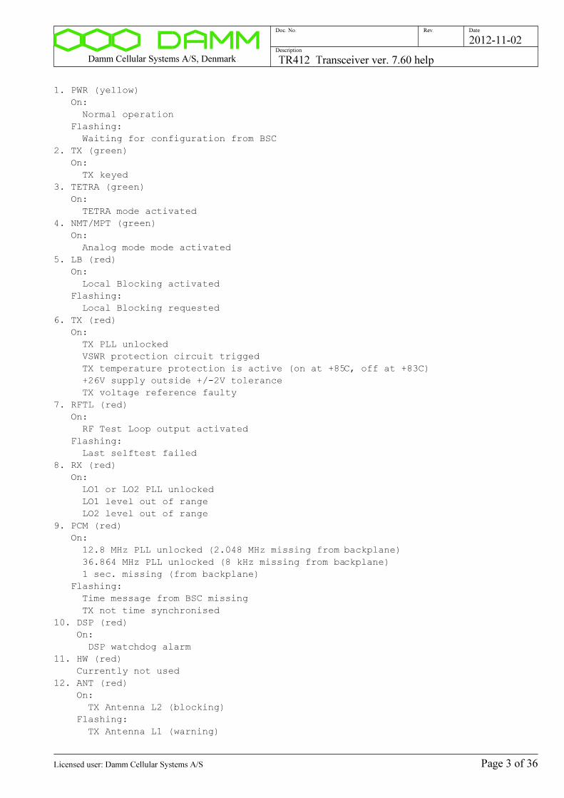
Damm Cellular Systems A/S, Denmark TR412 Transceiver ver. 7.60 help
Doc. No. Rev. Date
Description
2012-11-02
1. PWR (yellow)
On:
Normal operation
Flashing:
Waiting for configuration from BSC
2. TX (green)
On:
TX keyed
3. TETRA (green)
On:
TETRA mode activated
4. NMT/MPT (green)
On:
Analog mode mode activated
5. LB (red)
On:
Local Blocking activated
Flashing:
Local Blocking requested
6. TX (red)
On:
TX PLL unlocked
VSWR protection circuit trigged
TX temperature protection is active (on at +85C, off at +83C)
+26V supply outside +/-2V tolerance
TX voltage reference faulty
7. RFTL (red)
On:
RF Test Loop output activated
Flashing:
Last selftest failed
8. RX (red)
On:
LO1 or LO2 PLL unlocked
LO1 level out of range
LO2 level out of range
9. PCM (red)
On:
12.8 MHz PLL unlocked (2.048 MHz missing from backplane)
36.864 MHz PLL unlocked (8 kHz missing from backplane)
1 sec. missing (from backplane)
Flashing:
Time message from BSC missing
TX not time synchronised
10. DSP (red)
On:
DSP watchdog alarm
11. HW (red)
Currently not used
12. ANT (red)
On:
TX Antenna L2 (blocking)
Flashing:
TX Antenna L1 (warning)
Page 3 of 36Licensed user: Damm Cellular Systems A/S

Damm Cellular Systems A/S, Denmark TR412 Transceiver ver. 7.60 help
Doc. No. Rev. Date
Description
2012-11-02
TX combiner TP alarm
13. H/E (red)
On:
Any of the external alarm inputs activated
14. RM (red)
On:
Both RX signal paths faulty
Flashing:
One of the two RX signal paths faulty
Individual alarm flags can be displayed with the 03 commands.
Page 4 of 36Licensed user: Damm Cellular Systems A/S
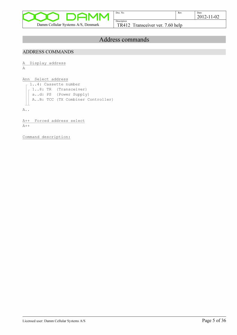
Damm Cellular Systems A/S, Denmark TR412 Transceiver ver. 7.60 help
Doc. No. Rev. Date
Description
2012-11-02
Address commands
ADDRESS COMMANDS
A Display address
A
Ann Select address
1..4: Cassette number
1..8: TR (Transceiver)
a..d: PS (Power Supply)
A..B: TCC (TX Combiner Controller)
A..
A++ Forced address select
A++
Command description:
Page 5 of 36Licensed user: Damm Cellular Systems A/S
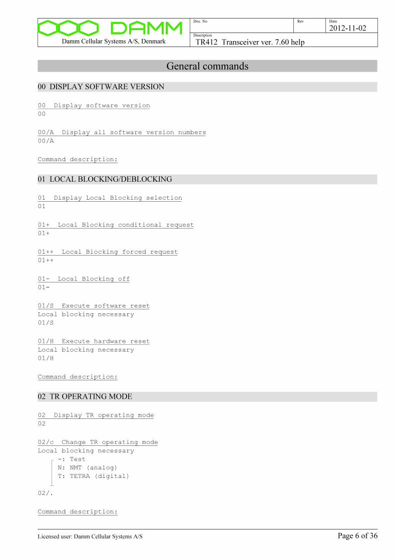
Damm Cellular Systems A/S, Denmark TR412 Transceiver ver. 7.60 help
Doc. No. Rev. Date
Description
2012-11-02
General commands
00 DISPLAY SOFTWARE VERSION
00 Display software version
00
00/A Display all software version numbers
00/A
Command description:
01 LOCAL BLOCKING/DEBLOCKING
01 Display Local Blocking selection
01
01+ Local Blocking conditional request
01+
01++ Local Blocking forced request
01++
01- Local Blocking off
01-
01/S Execute software reset
Local blocking necessary
01/S
01/H Execute hardware reset
Local blocking necessary
01/H
Command description:
02 TR OPERATING MODE
02 Display TR operating mode
02
02/c Change TR operating mode
Local blocking necessary
-: Test
N: NMT (analog)
T: TETRA (digital)
02/.
Command description:
Page 6 of 36Licensed user: Damm Cellular Systems A/S

Damm Cellular Systems A/S, Denmark TR412 Transceiver ver. 7.60 help
Doc. No. Rev. Date
Description
2012-11-02
03 TR ALARMS
03 Display TR Alarm state
03
03/A Display Internal Alarms
03/A
03/B Display BSC Alarms
03/B
03/E Display External Alarms
03/E
03/C Clear TR alarms
03/C
03/L Display alarm latching selection
03/L
03/L/s Change alarm latching selection
Local blocking necessary
-: Disable alarm latching
+: Enable alarm latching (default)
03/L/.
Command description:
05 DISPLAY CONFIG/STATUS FROM BSC
05 Display Config/Status from BSC
05
Command description:
07 DISPLAY DATE AND TIME
07 Display date/time
07
07/S Display date/time status
07/S
07/T Display DSP TETRA Counters
07/T
Command description:
Page 7 of 36Licensed user: Damm Cellular Systems A/S
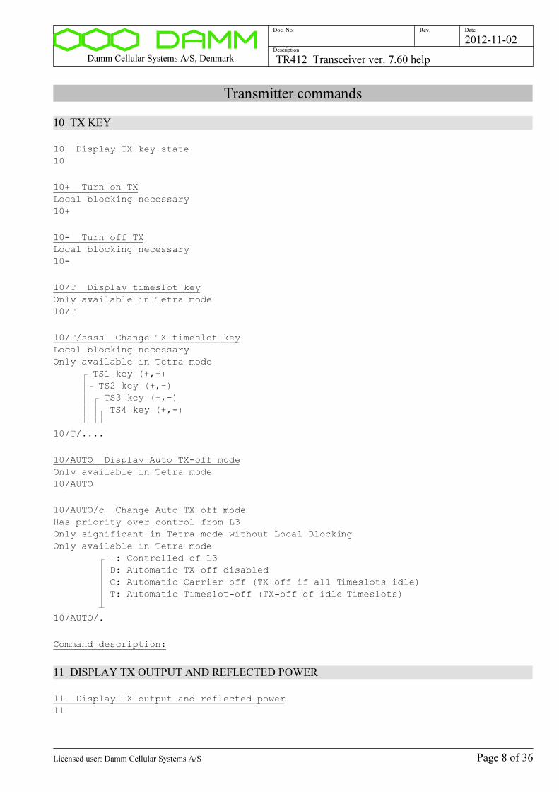
Damm Cellular Systems A/S, Denmark TR412 Transceiver ver. 7.60 help
Doc. No. Rev. Date
Description
2012-11-02
Transmitter commands
10 TX KEY
10 Display TX key state
10
10+ Turn on TX
Local blocking necessary
10+
10- Turn off TX
Local blocking necessary
10-
10/T Display timeslot key
Only available in Tetra mode
10/T
10/T/ssss Change TX timeslot key
Local blocking necessary
Only available in Tetra mode
TS1 key (+,-)
TS2 key (+,-)
TS3 key (+,-)
TS4 key (+,-)
10/T/....
10/AUTO Display Auto TX-off mode
Only available in Tetra mode
10/AUTO
10/AUTO/c Change Auto TX-off mode
Has priority over control from L3
Only significant in Tetra mode without Local Blocking
Only available in Tetra mode
-: Controlled of L3
D: Automatic TX-off disabled
C: Automatic Carrier-off (TX-off if all Timeslots idle)
T: Automatic Timeslot-off (TX-off of idle Timeslots)
10/AUTO/.
Command description:
11 DISPLAY TX OUTPUT AND REFLECTED POWER
11 Display TX output and reflected power
11
Page 8 of 36Licensed user: Damm Cellular Systems A/S
Damm Cellular Systems A/S, Denmark TR412 Transceiver ver. 7.60 help
Doc. No. Rev. Date
Description
2012-11-02
Command description:
12 DISPLAY TX COMBINER TESTPOINT VALUE
12 Display TX combiner TP value
12
Command description:
13 TX OUTPUT POWER LEVEL SELECTIONS
13 Display TX output power selection
13
13/+nn.n Change TX output power
Local blocking necessary
The setting is saved with the 70/SAVE command
The selected power is TETRA mean power on TR connector
Maxim Peak Envelope Power is 3.8dB higher
For NMT/MPT (analog PM) power is +3dB the selected power
For Test mode single tone, mean power is equal to Peak Envelope Power
For Test mode two-tone, mean power is -3dB of Peak Envelope Power
Output power selection
TR412 : 30.0 to 44.0 [dBm]
TR412H: 34.0 to 48.0 [dBm]
13/+....
13/MIN Change TX output power to minimum
Local blocking necessary
The setting is saved with the 70/SAVE command
13/MIN
13/MAX Change TX output power to maximum
Local blocking necessary
The setting is saved with the 70/SAVE command
13/MAX
Page 9 of 36Licensed user: Damm Cellular Systems A/S

Damm Cellular Systems A/S, Denmark TR412 Transceiver ver. 7.60 help
Doc. No. Rev. Date
Description
2012-11-02
13/RED/+nn.n Change Reduced TX output power
Local blocking necessary
Power setting for Reduced Power (Alarm Input 8 activated)
The setting is saved with the 70/SAVE command
The selected power is TETRA mean power on TR connector
Maxim Peak Envelope Power is 3.8dB higher
For NMT/MPT (analog PM) power is +3dB the selected power
For Test mode single tone, mean power is equal to Peak Envelope Power
For Test mode two-tone, mean power is -3dB of Peak Envelope Power
Reduced Output power selection
TR412 : 30.0 to 44.0 [dBm]
TR412H: 34.0 to 48.0 [dBm]
13/RED/+....
13/RED/MIN Change Reduced TX output power to minimum
Local blocking necessary
Power setting for Reduced Power (Alarm Input 8 activated)
The setting is saved with the 70/SAVE command
13/RED/MIN
13/RED/MAX Change Reduced TX output power to maximum
Local blocking necessary
Power setting for Reduced Power (Alarm Input 8 activated)
The setting is saved with the 70/SAVE command
13/RED/MAX
Command description:
15 Display TX test modulation selection
15
15/ZERO Select zero modulation
I and Q DAC set to zero (with zero offset compensation)
15/ZERO
15/CW Select CW modulation
Power level analog-value of selected power (5/6 of pep)
15/CW
15/CW/PEP Select CW modulation PEP value
Power level is pep-value of selected power
15/CW/PEP
15/CW/IQ Display I/Q values for CW modulation
15/CW/IQ
Page 10 of 36Licensed user: Damm Cellular Systems A/S

Damm Cellular Systems A/S, Denmark TR412 Transceiver ver. 7.60 help
Doc. No. Rev. Date
Description
2012-11-02
15/CW/cs Select CW modulation
I: I DAC output
Q: Q DAC output
+: Positive DAC output
-: Negative DAC output
15/CW/..
15/CW/IQ/snnnnn/snnnnn Select CW modulation with I/Q values
NB: I and Q values are modified with power setting, I+Q offset
and quadrature settings before reaching the DACs.
I-value (-32768..+32767)
Q-value (-32768..+32767)
15/CW/IQ/....../......
15/DSB/c/n Select DSB modulation
I: I generated DSB modulation
Q: Q generated DSB modulation
2: 2.25 kHz
4: 4.50 kHz
9: 9.00 kHz
15/DSB/./.
15/cSB/n Select SSB modulation
L: LSB (Lower Side Band)
U: USB (Upper Side Band)
2: 2.25 kHz
4: 4.50 kHz
15/.SB/.
15/PRBS9 Select TETRA PRBS-9 modulation
15/PRBS9
15/PRBS15 Select TETRA PRBS-15 modulation
15/PRBS15
15/PH45 Select TETRA +/-45deg. modulation
15/PH45
15/FM/3 Select FM 1kHz +/-3kHz
15/FM/3
15/MULTI Select DSB multitone modulation
15/MULTI
Page 11 of 36Licensed user: Damm Cellular Systems A/S
Damm Cellular Systems A/S, Denmark TR412 Transceiver ver. 7.60 help
Doc. No. Rev. Date
Description
2012-11-02
16 TX FILTER
16 Display TX filter type
16
16/n Change TX filter type
TX filter type
0: TETRA 25kHz ch. spacing
1: Flat (for test)
16/.
Command description:
17 Display TX status
17
17/IQ Display TX IQ values
17/IQ
18 TX CARTESIAN LOOP COMMANDS
18 Display cartesian loop selection
18
18- Select open cartesian loop
18-
18+ Select closed cartesian loop
18+
18/P TX cartesian loop phase measurement
18/P
18/A TX cartesian loop phase/ampl. measurement
18/A
18/FREQ TX cartesian loop phase vs frequency measurement
18/FREQ
18/PWR TX cartesian loop phase vs. power measurement
18/PWR
18/ADJUST TX cartesian open loop phase adjust
WARNING: Factory adjust command, factory unlock necessary
Changes same parameter as the 91/PH0/snnn command
18/ADJUST
Command description:
Page 12 of 36Licensed user: Damm Cellular Systems A/S
Damm Cellular Systems A/S, Denmark TR412 Transceiver ver. 7.60 help
Doc. No. Rev. Date
Description
2012-11-02
19 TX PLL/KEY COMMANDS
19 Display command function
19
19/F Select fast TX PLL loop
Local blocking necessary
19/F
19/S Select slow TX PLL loop
Local blocking necessary
19/S
19/FREQ Display TX PLL voltage vs frequency
Local blocking necessary
19/FREQ
19+ Switch TX on and off continuously
Local blocking necessary
19+
19/nnnn Switch TX channel continuously between current and nnnn
Local blocking necessary
TX channel number
19/....
Command description:
Page 13 of 36Licensed user: Damm Cellular Systems A/S
Damm Cellular Systems A/S, Denmark TR412 Transceiver ver. 7.60 help
Doc. No. Rev. Date
Description
2012-11-02
Receiver commands
20 RX LO
20 Display RX LO status
20
Command description:
21 DISPLAY RX RSSI
21 Display RX RSSI
With 5 msec. settling time
21
21/c Display RX RSSI
RSSI option
0: 100 msec. settling time
1: 1 sec. settling time
Q: 5 msec. settling time without header
21/.
21/NF Display RX Noise Figure
Displays the RSSI value as equivalent Noise Figure
The reference depends on the actual IF filter
bandwidth, see the 26 command
21/NF
21/FFT/c Display FFT result
RX path:
A: RX-A
B: RX-B
21/FFT/.
21/FFT/c/2 Display 2.25kHz FFT amplitude results
Response is:
-nnn.n :-6.75 kHz [dBm]
-nnn.n :-2.25 kHz [dBm]
-nnn.n : 0.00 kHz [dBm]
-nnn.n :+2.25 kHz [dBm]
-nnn.n :+6.75 kHz [dBm]
RX path:
A: RX-A
B: RX-B
21/FFT/./2
Command description:
Page 14 of 36Licensed user: Damm Cellular Systems A/S

Damm Cellular Systems A/S, Denmark TR412 Transceiver ver. 7.60 help
Doc. No. Rev. Date
Description
2012-11-02
22 RX DIVERSITY
22 Display RX diversity selection
22
22/A A-forced RX diversity selection
22/A
22/B B-forced RX diversity selection
22/B
22- Automatic RX diversity selection
22-
Command description:
23 RX ANTENNA TEST
23 Display command function
23
23+ RX antenna measurement command
23+
Command description:
25 Display RX test demodulation mode
25
25/PM Select PM demodulation
25/PM
25/FFT Select FFT demodulation
25/FFT
26 RX FILTER
26 Display RX filter type
26
26/n Change RX filter type
RX filter type
0: TETRA 25kHz ch. spacing
1: PM 25kHz ch. spacing (+/-7.5kHz)
2: PM 25kHz ch. spacing interleaved (+/-6.5kHz)
3: PM 20kHz ch. spacing (+/-6kHz)
4: PM 12.5kHz ch. spacing (+/-3.75kHz)
5: Flat (for test)
26/.
Page 15 of 36Licensed user: Damm Cellular Systems A/S
Damm Cellular Systems A/S, Denmark TR412 Transceiver ver. 7.60 help
Doc. No. Rev. Date
Description
2012-11-02
Command description:
27 RX SIGNAL DISPLAY COMMANDS
27 Display command function
27
27/ADC Display RX ADC signals
27/ADC
27/CP/c Display TETRA constellation points
RX path:
A: RX-A
B: RX-B
27/CP/.
Command description:
28 RX ADJUST COMMANDS
28 Display command function
28
28/LO Display LO1 injection
28/LO
28/PLL Display LO1 PLL voltage vs frequency
28/PLL
Command description:
29 SWITCH RX CHANNEL CONTINUOUSLY
29 Display command 29 function
29
29/F Select fast TX FS loop
29/F
29/S Select slow TX FS loop
29/S
29/nnnn Switch RX channel continuously between current and nnnn
Local blocking necessary
RX channel number
29/....
Command description:
Page 16 of 36Licensed user: Damm Cellular Systems A/S
Damm Cellular Systems A/S, Denmark TR412 Transceiver ver. 7.60 help
Doc. No. Rev. Date
Description
2012-11-02
Response:
1) RX FS switch command 29 response
2) RX FS switch cont. 29/nnnn response
Description:
The 29+ and 29/nnnn commands starts a continuous switching between two channels.
Page 17 of 36Licensed user: Damm Cellular Systems A/S
Damm Cellular Systems A/S, Denmark TR412 Transceiver ver. 7.60 help
Doc. No. Rev. Date
Description
2012-11-02
Common commands
30 CHANNEL COMMANDS
30 Display RX+TX channel numbers
30
30/nnnn Change RX+TX channel number
The setting is saved with the 70/SAVE command
NB: Channel Number step size depends on factory settings (see 93 commands)
Channel number
30/....
30/R/nnnn Change RX channel number
The setting is saved with the 70/SAVE command
NB: Channel Number step size depends on factory settings (see 93 commands)
RX channel number
30/R/....
30/T/nnnn Change TX channel number
The setting is saved with the 70/SAVE command
NB: Channel Number step size depends on factory settings (see 93 commands)
TX channel number
30/T/....
30/R/nnnn.nnnnnn Change RX frequency
The setting is saved with the 70/SAVE command
NB: Frequency range and step size depends on factory settings (see 93 commands)
Frequency [MHz]
30/R/...........
30/T/nnnn.nnnnnn Change TX frequency
The setting is saved with the 70/SAVE command
NB: Frequency range and step size depends on factory settings (see 93 commands)
Frequency [MHz]
30/T/...........
Command description:
31 Display BSC signals and PLL status
31
32 Display RFTL selection
32
Page 18 of 36Licensed user: Damm Cellular Systems A/S

Damm Cellular Systems A/S, Denmark TR412 Transceiver ver. 7.60 help
Doc. No. Rev. Date
Description
2012-11-02
32+ Turn on RFTL high
Turns on output to -40dBr
32+
32/L Turn on RFTL low
Turns on output to -50dBr
Not supported in older hardware versions
32/L
32- Turn off RFTL
32-
33 PCM HIGHWAY
33 Display PCM highway selections
33
33/c/s PCM highway loopback control
When activated, the incoming timeslot bitstream is returned on
the outgoing timeslot.
TR timeslot number
1: TR timeslot 1
2: TR timeslot 2
3: TR timeslot 3
4: TR timeslot 4
A: All 4 TR timeslots
+: Activate loopback
-: Stop loopback
33/./.
Command description:
Highway timeslot numbers:
Pos: x1 x2 x3 x4 x5 x6 x7 x8
---- -- -- -- -- -- -- -- --
TS1: 00 04 08 12 16 20 24 28
TS2: 01 05 09 13 17 21 25 29
TS3: 02 06 10 14 18 22 26 30
TS4: 03 07 11 15 19 23 27 31
34 CMoIP
34 Display CMoIP status
34
34/C Clear CMoIP Downlink statistics counters
34/C
Command description:
Page 19 of 36Licensed user: Damm Cellular Systems A/S
Damm Cellular Systems A/S, Denmark TR412 Transceiver ver. 7.60 help
Doc. No. Rev. Date
Description
2012-11-02
35 BLOWER
35 Display blower state
35
35+ Select forced fast Blower
35+
35- Deselect forced fast Blower
35-
Command description:
All blowers mounted below the TR cassette can run with two
speeds (except for backplanes from before 2001).
Under normal conditions, all blowers are running with slow speed.
When any of the mounted TR412 in that cassette exceeds the temperature
+60C, it will force the blower speed to fast speed.
When the temperature on that transceiver again drops below +55, it will
stop forcing the blowers to fast speed.
Fast blower speed can also be selected for test purposes with O&M
commands.
43 Display Timeslot status
43
43/CNTR Display counter values
43/CNTR
43/CNTR/C Clear counter values
43/CNTR/C
43/CONST/n/c Display constellation points
Timeslot number (1..4)
RX path (A or B)
43/CONST/./.
48 Display Message Trace
48
49 Display Tetra channel test selection
49
Page 20 of 36Licensed user: Damm Cellular Systems A/S
Damm Cellular Systems A/S, Denmark TR412 Transceiver ver. 7.60 help
Doc. No. Rev. Date
Description
2012-11-02
49/CHTST/nn/n Activate Tetra channel test
Uplink test point channel type:
07: TCH/7.2
08: SCH/F
09: STCH
10: TCH/2.4 N=1
11: SCH/HU
16: TCH/S
18: TCH/4.8 N=1
Downlink test point channel type:
57: TCH/7.2
60: TCH/2.4 N=1
66: TCH/S
68: TCH/4.8 N=1
Timeslot (1..4)
49/CHTST/../.
49- Stop Tetra channel test
49-
Command description:
The 49 commands control the TR412 build-in TETRA channel test features.
When channel test is activated, a test point at the output from the receiver
or alternatively at the input from the PCM highway is selected. Received bursts
including status will be send to the BSC via the HDLC bus, where BER/MER mea-
surements can be made with the F49 commands.
When channel test is activated, the TR412 TX switches to uplink mode and
generates the selected channel type. When TX is keyed and RFTL activated,
an RX input signal can be generated for the testing.
Alternatively, a test signal can be generated from an external source, e.g.
an R&S SMIQ or Anritsu signal generator
The uplink test point is intended for normal receiver channel tests.
The downlink test point is intented for test of received circuit mode traffic
transmitted via the PCM highway, and optionally an E1 connection and the
looped back. The signal can be generated on one TR412 and monitored on a
downlink
testpoint on another TR412 on the same or another BS.
Page 21 of 36Licensed user: Damm Cellular Systems A/S
Damm Cellular Systems A/S, Denmark TR412 Transceiver ver. 7.60 help
Doc. No. Rev. Date
Description
2012-11-02
Test commands
60 DC VOLTMETER
60 Display DC test points
60
60/A Display all DC test points
60/A
60/nn Display specific DC test point
TP number (00..16)
60/..
60/T Display temperature
60/T
60/REF Display DC voltmeter reference voltage
60/REF
Command description:
Description:
The command displays the DC voltage on one of the xx DC test points.
The displayed reading is taken from a RAM register array, which is updated
every 24/1000 sec. Therefore, some delay can be necessary in connection
with automatic test equipment.
61 Display DSP state
61
61/CNTR Display DSP counters
61/CNTR
61/CNTR/C Clear DSP counters
61/CNTR/C
61- Stop DSP execution
Activates DSP hardware reset
61-
Page 22 of 36Licensed user: Damm Cellular Systems A/S
Damm Cellular Systems A/S, Denmark TR412 Transceiver ver. 7.60 help
Doc. No. Rev. Date
Description
2012-11-02
61+ Restart DSP
Makes:
1) Hardware reset on
2) Hardware reset off
3) DSP memory clear
4) DSP code installation
5) Interface register init
6) Program execution start
61+
61/+ Release DSP reset
DSP reset state necessary
Afterward, manual R/W can be done
61/+
61/B Boot DSP without execution
Makes:
1) Hardware reset on
2) Hardware reset off
3) DSP memory clear
4) DSP code installation
5) Interface register init
Afterward, manual R/W and program execution start can be done
61/B
61/R Start DSP program run
DSP booted state necessary
61/R
61/hhhhhhhh Display DSP memory word
DSP memory address (32-bit aligned hex)
61/........
61/hhhhhhh0/B Display DSP memory byte-wise
DSP memory address (hex)
61/.......0/B
61/hhhhhhh0/W Display DSP memory word-wise
DSP memory address (hex)
61/.......0/W
61/hhhhhhh0/D Display DSP memory doublewordwise
DSP memory address (hex)
61/.......0/D
Page 23 of 36Licensed user: Damm Cellular Systems A/S
Damm Cellular Systems A/S, Denmark TR412 Transceiver ver. 7.60 help
Doc. No. Rev. Date
Description
2012-11-02
61/REG/c Display DSP interface registers
D: DSP control/status registers
C: Radio calibration registers
R: Radio control registers
S: Radio status registers
M: Message queue registers
T: Tetra mode registers
61/REG/.
61/hhhhhhhh/hhhhhhhh Change DSP memory
DSP memory address (32-bit aligned hex)
Data to write (hex)
61/......../........
61/HPIC DSP HPIC read-back
61/HPIC
61/HPIA/hhhhhhhh DSP HPIA write/read test
Value to write to HPIA (hex)
61/HPIA/........
65 HDLC BUS MESSAGE QUEUE
65 Display command function
65
65/N Display next HDLC message
65/N
65/C Clear HDLC test queue
65/C
65/S Set HDLC test queue to start
65/S
65/s Message display suppress control
+: Display all messages
-: Suppress $0A, $0F, $33, $8A, $8C, $8F and $B3 messages (default)
65/.
65/ADDR Display HDLC queue addresses
65/ADDR
65/OWN Display OWN bits
65/OWN
Page 24 of 36Licensed user: Damm Cellular Systems A/S
Damm Cellular Systems A/S, Denmark TR412 Transceiver ver. 7.60 help
Doc. No. Rev. Date
Description
2012-11-02
65/BUF Display current HDLC descriptors
65/BUF
65/BUF/nnn Display HDLC descriptors
Ring descriptor index (000..127)
65/BUF/...
65/hhhhhhhh..hh Send HDLC message to BSC
Message in hex
1 2 3 4 5 6 7 8 9 0 1 2 3 4 5 6 7 8 9 0 1 2 3 4 5 6 7 8 9 0 1 2 3 4 5 6 7
ÿ ¿ ¿ ¿ ¿ ¿ ¿ ¿ ¿ ¿ ¿ ¿ ¿ ¿ ¿ ¿ ¿ ¿ ¿ ¿ ¿ ¿ ¿ ¿ ¿ ¿ ¿ ¿ ¿ ¿ ¿ ¿ ¿ ¿ ¿ ¿ ¿
65/..........................................................................
65/TST Display HDLC test variables
65/TST
65/TST/c Start/stop sending HDLC test messages
B: Send messages looped-back in BSC
I: Send messages looped-back in BSC IP stack
O: Send messages looped-back in other BSC
S: Send messages looped-back in BSS/SC
-: Stop sending messages
65/TST/.
65/TST/C Clear HDLC test error counters
65/TST/C
65/TST/nn/nnn/nn Change HDLC test message output parameters
Numer of messages send each time (01..99)
Send repetition time (001..999 msec.)
Payload length (00..99)
65/TST/../.../..
Command description:
66 CPU LOAD COMMAND
66 Display CPU load
66
66/C Clear max-counter values
66/C
66/LOAD Display random load value
66/LOAD
Page 25 of 36Licensed user: Damm Cellular Systems A/S
Damm Cellular Systems A/S, Denmark TR412 Transceiver ver. 7.60 help
Doc. No. Rev. Date
Description
2012-11-02
66/LOAD/nnnn Change random load value
Random load value (0000..9999)
66/LOAD/....
Command description:
67 INPUT/OUTPUT COMMANDS
67/LEDS Display LED state
67/LEDS
67/ADDRPORT Display address port
67/ADDRPORT
Command description:
68 PROGRAM DOWNLOAD
68 Display command
68
68/DOWNLOAD Request program download from BSC
1) Mark download request in flash
2) Make hardware reset to enter download mode
68/DOWNLOAD
68/CHKSUM Display flash checksum
68/CHKSUM
Command description:
69 DISPLAY MEMORY
69 Display boot program version number
69
69/hhhh0 Display memory area
Memory address segment ($0000..$FFFF)
69/....0
69/D/hhh0 Display data segment area
Data segment offset ($0000..$FFF0)
69/D/...0
69/ADDR Display memory addresses
69/ADDR
Page 26 of 36Licensed user: Damm Cellular Systems A/S
Damm Cellular Systems A/S, Denmark TR412 Transceiver ver. 7.60 help
Doc. No. Rev. Date
Description
2012-11-02
69/IO/hhhh Display I/O Port
I/O Address ($0000..$FFFF)
69/IO/....
Command description:
Description:
The command displayes the contents of a memory area of the AM186CC microcontroller.
Page 27 of 36Licensed user: Damm Cellular Systems A/S

Damm Cellular Systems A/S, Denmark TR412 Transceiver ver. 7.60 help
Doc. No. Rev. Date
Description
2012-11-02
System configuration
70 Display system configuration status
70
70/SAVE Save system configuration in flash
70/SAVE
70/CNFG Return system configuration
70/CNFG
71 Display TX settings
71
71/TCTP/n.nnn Change TX Combiner TP alarm threshold
TX Combiner TP alarm threshold (0.000..5.000VDC)
71/TCTP/.....
72 Display RX settings
72
72/PREGAIN/n.n Change RX pre-gain setting
RX pre-gain in dB (0.0..9.9, nom. 6.0)
72/PREGAIN/...
Page 28 of 36Licensed user: Damm Cellular Systems A/S
Damm Cellular Systems A/S, Denmark TR412 Transceiver ver. 7.60 help
Doc. No. Rev. Date
Description
2012-11-02
Factory configuration
90 Display factory configuration status
90
90/FACTORYUNLOCK Select factory configuration unlock
UNLOCK
90/FACTORY......
90- Deselect factory configuration unlock
90-
90/SAVE Save factory configuration in flash
90/SAVE
90/CNFG Return factory configuration
90/CNFG
Page 29 of 36Licensed user: Damm Cellular Systems A/S
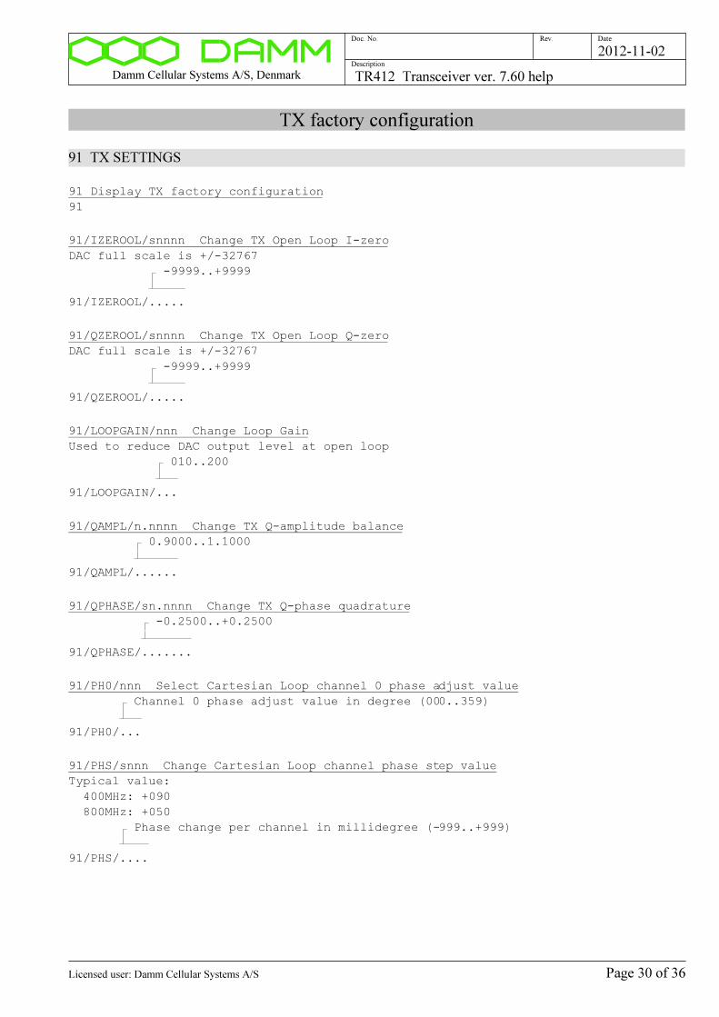
Damm Cellular Systems A/S, Denmark TR412 Transceiver ver. 7.60 help
Doc. No. Rev. Date
Description
2012-11-02
TX factory configuration
91 TX SETTINGS
91 Display TX factory configuration
91
91/IZEROOL/snnnn Change TX Open Loop I-zero
DAC full scale is +/-32767
-9999..+9999
91/IZEROOL/.....
91/QZEROOL/snnnn Change TX Open Loop Q-zero
DAC full scale is +/-32767
-9999..+9999
91/QZEROOL/.....
91/LOOPGAIN/nnn Change Loop Gain
Used to reduce DAC output level at open loop
010..200
91/LOOPGAIN/...
91/QAMPL/n.nnnn Change TX Q-amplitude balance
0.9000..1.1000
91/QAMPL/......
91/QPHASE/sn.nnnn Change TX Q-phase quadrature
-0.2500..+0.2500
91/QPHASE/.......
91/PH0/nnn Select Cartesian Loop channel 0 phase adjust value
Channel 0 phase adjust value in degree (000..359)
91/PH0/...
91/PHS/snnn Change Cartesian Loop channel phase step value
Typical value:
400MHz: +090
800MHz: +050
Phase change per channel in millidegree (-999..+999)
91/PHS/....
Page 30 of 36Licensed user: Damm Cellular Systems A/S
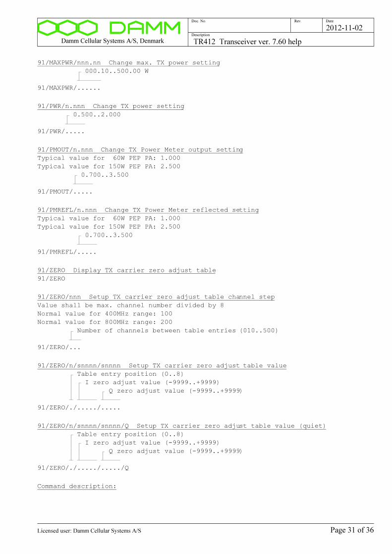
Damm Cellular Systems A/S, Denmark TR412 Transceiver ver. 7.60 help
Doc. No. Rev. Date
Description
2012-11-02
91/MAXPWR/nnn.nn Change max. TX power setting
000.10..500.00 W
91/MAXPWR/......
91/PWR/n.nnn Change TX power setting
0.500..2.000
91/PWR/.....
91/PMOUT/n.nnn Change TX Power Meter output setting
Typical value for 60W PEP PA: 1.000
Typical value for 150W PEP PA: 2.500
0.700..3.500
91/PMOUT/.....
91/PMREFL/n.nnn Change TX Power Meter reflected setting
Typical value for 60W PEP PA: 1.000
Typical value for 150W PEP PA: 2.500
0.700..3.500
91/PMREFL/.....
91/ZERO Display TX carrier zero adjust table
91/ZERO
91/ZERO/nnn Setup TX carrier zero adjust table channel step
Value shall be max. channel number divided by 8
Normal value for 400MHz range: 100
Normal value for 800MHz range: 200
Number of channels between table entries (010..500)
91/ZERO/...
91/ZERO/n/snnnn/snnnn Setup TX carrier zero adjust table value
Table entry position (0..8)
I zero adjust value (-9999..+9999)
Q zero adjust value (-9999..+9999)
91/ZERO/./...../.....
91/ZERO/n/snnnn/snnnn/Q Setup TX carrier zero adjust table value (quiet)
Table entry position (0..8)
I zero adjust value (-9999..+9999)
Q zero adjust value (-9999..+9999)
91/ZERO/./...../...../Q
Command description:
Page 31 of 36Licensed user: Damm Cellular Systems A/S
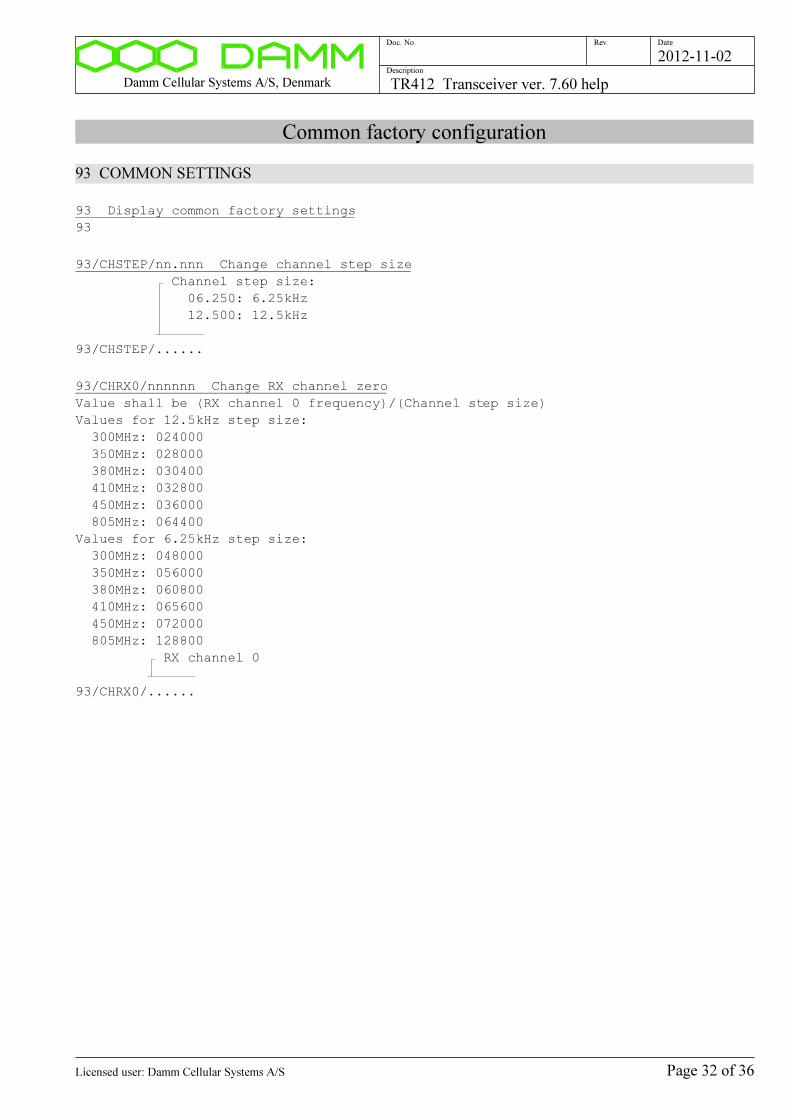
Damm Cellular Systems A/S, Denmark TR412 Transceiver ver. 7.60 help
Doc. No. Rev. Date
Description
2012-11-02
Common factory configuration
93 COMMON SETTINGS
93 Display common factory settings
93
93/CHSTEP/nn.nnn Change channel step size
Channel step size:
06.250: 6.25kHz
12.500: 12.5kHz
93/CHSTEP/......
93/CHRX0/nnnnnn Change RX channel zero
Value shall be (RX channel 0 frequency)/(Channel step size)
Values for 12.5kHz step size:
300MHz: 024000
350MHz: 028000
380MHz: 030400
410MHz: 032800
450MHz: 036000
805MHz: 064400
Values for 6.25kHz step size:
300MHz: 048000
350MHz: 056000
380MHz: 060800
410MHz: 065600
450MHz: 072000
805MHz: 128800
RX channel 0
93/CHRX0/......
Page 32 of 36Licensed user: Damm Cellular Systems A/S
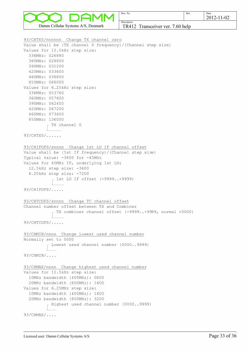
Damm Cellular Systems A/S, Denmark TR412 Transceiver ver. 7.60 help
Doc. No. Rev. Date
Description
2012-11-02
93/CHTX0/nnnnnn Change TX channel zero
Value shall be (TX channel 0 frequency)/(Channel step size)
Values for 12.5kHz step size:
336MHz: 026880
360MHz: 028800
390MHz: 031200
420MHz: 033600
460MHz: 036800
850MHz: 068000
Values for 6.25kHz step size:
336MHz: 053760
360MHz: 057600
390MHz: 062400
420MHz: 067200
460MHz: 073600
850MHz: 136000
TX channel 0
93/CHTX0/......
93/CHIFOFS/snnnn Change 1st LO IF channel offset
Value shall be (1st IF frequency)/(Channel step size)
Typical value: -3600 for -45MHz
Values for 45MHz IF, underlying 1st LO:
12.5kHz step size: -3600
6.25kHz step size: -7200
1st LO IF offset (-9999..+9999)
93/CHIFOFS/.....
93/CHTCOFS/snnnn Change TC channel offset
Channel number offset between TX and Combiner
TX combiner channel offset (-9999..+9999, normal +0000)
93/CHTCOFS/.....
93/CHMIN/nnnn Change lowest used channel number
Normally set to 0000
Lowest used channel number (0000..9999)
93/CHMIN/....
93/CHMAX/nnnn Change highest used channel number
Values for 12.5kHz step size:
10MHz bandwidth (400MHz): 0800
20MHz bandwidth (800MHz): 1600
Values for 6.25MHz step size:
10MHz bandwidth (400MHz): 1600
20MHz bandwidth (800MHz): 3200
Highest used channel number (0000..9999)
93/CHMAX/....
Page 33 of 36Licensed user: Damm Cellular Systems A/S
Damm Cellular Systems A/S, Denmark TR412 Transceiver ver. 7.60 help
Doc. No. Rev. Date
Description
2012-11-02
Command description:
Page 34 of 36Licensed user: Damm Cellular Systems A/S
Damm Cellular Systems A/S, Denmark TR412 Transceiver ver. 7.60 help
Doc. No. Rev. Date
Description
2012-11-02
Test circuit configuration
96 TEST CIRCUIT SETTINGS
96 Display Test circuit settings
96
96/DCVM/n.nnn Change DC Voltmeter calibration constant
Calibration constant (4.700..5.300, nom. 5.000)
96/DCVM/.....
96/THERM/snn.n Change Thermometer calibration offset
Calibration offset (-99.9..+99.9, nom. +00.0)
96/THERM/.....
Command description:
Page 35 of 36Licensed user: Damm Cellular Systems A/S
Damm Cellular Systems A/S, Denmark TR412 Transceiver ver. 7.60 help
Doc. No. Rev. Date
Description
2012-11-02
Hardware identity
98 HARDWARE ID
98 Display hardware ID
98
98/TYPE Display type number
98/TYPE
98/ITEM Display item number
98/ITEM
98/SER Display serial number
98/SER
98/VER Display version number
98/VER
98/REV Display revision number
98/REV
98/ITEM/cc..c Change item number
Item number
98/ITEM/...............
98/SER/cc..c Change serial number
Serial number
98/SER/........
98/VER/n.nn Change version number
Version number
98/VER/....
98/REV/n Change revision number
Revision number (0..9)
98/REV/.
Command description:
Page 36 of 36Licensed user: Damm Cellular Systems A/S
Damm Cellular Systems A/S, Denmark TR421 Transceiver ver. 7.60 help
Doc. No. Rev. Date
Description
2012-11-02
TR421 Transceiver ver. 7.60 help
Functional Description:
FUNCTIONAL DESCRIPTION
All test commands for the TR421 Transceiver consist of a
2-digit command in the range 00 to 99 with an optionally parameter. Commands
without parameters are display-only commands and will not make any change
in the TR.
The commands are divided into groups, covering the different functions in
the TR. For example, all the TX commands are in the 10 to 19 group.
If the first two characters are not representing a valid number in the 00 to
99 range, an error message will be displayed:
Invalid TR421 command
If an unimplemented TR command is called, the following response is
displayed:
Unimplemented TR421 command
OPERATOR BLOCKING MODE
After power-on, the TR always starts in normal operating mode. If a given
command requires operator blocking, it is shown in the help for the command.
Commands that require operator blocking are not available during normal
operation for operator interference. If a protected command is called,
the following response is displayed:
Operator blocking necessary
Only commands with a parameter are protected. After activation of
operator blocking (01+), all commands except factory configuration commands
are available.
PARAMETERS
Two types of parameters are used.
Generally + is used as parameter to turn on, enable or step up and - is used
as parameter to turn off, disable or step down.
For more complex functions, a / is used as separator after the command no.
followed by the necessary no. of characters for the actual function.
If the parameter is not valid for the actual command, the following response
is displayed:
Invalid TR421 parameter
Page 1 of 69Licensed user: Damm Cellular Systems A/S
Damm Cellular Systems A/S, Denmark TR421 Transceiver ver. 7.60 help
Doc. No. Rev. Date
Description
2012-11-02
CONFIGURATION
Many calibration and system parameters are stored residently.
At power-up and reset all settings are copied into the
workspace RAM, from where the different software tasks takes the settings.
Any change in the configuration is only made in the workspace RAM. To store
the new configuration residently, a save command shall be made.
The configuration is divided into two separate entities:
1) System configuration
2) Factory configuration
System configuration parameters can be changed with the 7x commands. To save
the system configuration resistently, the command "70/SAVE" shall be
entered.
Factory configuration parameters can be changed with the 9x commands. To
protect the operator from accidentially changing the factory configuration
parameters, an access lock is implemented, giving the following message:
Factory configuration unlocking necessary
To get access to factory configuration changes, it is necessary to enter
the command "90/FACTORYUNLOCK". Unlocking can be turned off again with the
"90-" command.
To save the factory configuration, the command "90/SAVE" shall be entered.
The resident configuration is restored into the workspace RAM at software
reset (02+) or local deblocking (01-) if re-booting take place.
LED description
The BS421 has the following internal LEDs:
LED Color Marking Function
---- ------ ------- --------------------
D408 Yellow Pwr Power
D407 Green TX TX keyed
D406 Red Oper Operator Blocking
D405 Red RFTL RFTL activated
D404 Red TX TX Alarm
D403 Red RX RX Alarm
D402 Red CU Control Unit Alarm
D401 Red DSP DSP alarm
D400 Red Sync Sync Alarm
Individual alarm flags can be displayed with the 03 commands.
Boot Loader Reprogramming
Page 2 of 69Licensed user: Damm Cellular Systems A/S
Damm Cellular Systems A/S, Denmark TR421 Transceiver ver. 7.60 help
Doc. No. Rev. Date
Description
2012-11-02
The BS421 contains a Boot Loader in the on-board Flash.
The Boot Loader starts execution after Power-on or Hardware Reset.
The Boot Loader reads the Windows CE operation system contained in the
NK.bin file on the CF-Card into memory and starts its execution.
From version 7.30 the version of the Boot Loader is shown at TR421 startup
and with the 00/A command.
From version 7.30 the Boot Loader can also be reprogrammed of TR421.exe.
To update the Boot Loader, put the Boot.bin file in the root directory of
the CF-card (together with NK.bin) and restart the TR421.
The Boot Loader reprogramming will be shown on the screen at startup.
After the update the Boot.bin file shall be removed again to prevent
re-programming at every restart.
Warning: Do not turn off power of BS421 during update as this will
corrupt the BS421 Boot Loader!
Page 3 of 69Licensed user: Damm Cellular Systems A/S
Damm Cellular Systems A/S, Denmark TR421 Transceiver ver. 7.60 help
Doc. No. Rev. Date
Description
2012-11-02
Software Version:
00 DISPLAY SOFTWARE VERSION
00 Display software version
00
00/A Display all software version numbers
00/A
00/OM Display OM Connection status
00/OM
00/BSC Display BSC Connection status
00/BSC
Command description:
Page 4 of 69Licensed user: Damm Cellular Systems A/S

Damm Cellular Systems A/S, Denmark TR421 Transceiver ver. 7.60 help
Doc. No. Rev. Date
Description
2012-11-02
Operator Blocking:
01 OPERATOR BLOCKING/DEBLOCKING
01 Display Operator Blocking selection
01
01+ Operator Blocking request
01+
01- Operator Blocking off
Makes a restart of the TR421 service
01-
01/DEBUG Display Debug Commands Enable selection
01/DEBUG
01/DEBUG/+ Enable Debug Commands
NB: Should only be used of software developers!
01/DEBUG/+
01/DEBUG/- Disable Debug Commands
01/DEBUG/-
Command description:
Page 5 of 69Licensed user: Damm Cellular Systems A/S
Damm Cellular Systems A/S, Denmark TR421 Transceiver ver. 7.60 help
Doc. No. Rev. Date
Description
2012-11-02
Operating Mode:
02 TR OPERATING MODE
02 Display TR operating mode
02
02/c Change TR operating mode
Local blocking necessary
-: Test
A: Analog
T: TETRA
02/.
Command description:
Page 6 of 69Licensed user: Damm Cellular Systems A/S
Damm Cellular Systems A/S, Denmark TR421 Transceiver ver. 7.60 help
Doc. No. Rev. Date
Description
2012-11-02
Alarms:
03 ALARMS
03 Display Alarm State
03
03/A Display Alarm Flags
03/A
03/E Display BSC External Alarms
03/E
03/C Clear Alarms
03/C
03/LED Display LED State
03/LED
Command description:
Page 7 of 69Licensed user: Damm Cellular Systems A/S
Damm Cellular Systems A/S, Denmark TR421 Transceiver ver. 7.60 help
Doc. No. Rev. Date
Description
2012-11-02
BSC:
05 BSC
05 Display BSC status/configuration
05
Command description:
Page 8 of 69Licensed user: Damm Cellular Systems A/S
Damm Cellular Systems A/S, Denmark TR421 Transceiver ver. 7.60 help
Doc. No. Rev. Date
Description
2012-11-02
MAC Address:
06 NETWORK ADDRESSES
06 Display Network settings
06
06/MAC Display MAC Address
06/MAC
06/SYNC Synchronize Flash and Registry Settings
If Registry settings are valid, Flash is updated with Registry values,
else Registry settings are created from Flash values (if valid).
The synchronization is also done automatically at startup of TR421.dll.
The Flash mirror ensures, that Network Settings are not lost at update
of the WinCE Operating System (NK.bin), where a new registry i created.
06/SYNC
06/NAME/cc.c Setup Host Name
Sets the Windows CE Host Name.
The setting is saved in both Flash and Registry.
Recommended Name is "Nnnn-BS1-TRx", where nnn is Node Number and
x is TR number.
NB: Reboot of WinCE is needed afterwards (see 99/HWRESET command).
Host Name
06/NAME/...............
06/DHCP/s Setup DHCP
Sets to use DHCP or Fixed Addresses.
The setting is saved in both Flash and Registry.
NB: Reboot of WinCE is needed afterwards (see 99/HWRESET command).
DHCP selection
+: DHCP Server provides IP Address/Mask/Gateway
-: Manually entered IP Address/Mask/Gateway
06/DHCP/.
06/IPADDR/... Setup IP Address
Sets the IP Address.
The setting is saved in both Flash and Registry.
Recommended IP Address is 172.016.nnn.hhh, where nnn is Node Number
and hhh is 011..018 for TR1 to TR8.
NB: Reboot of WinCE is needed afterwards (see 99/HWRESET command).
IP Address (0..255 in each field)
06/IPADDR/...............
Page 9 of 69Licensed user: Damm Cellular Systems A/S
Damm Cellular Systems A/S, Denmark TR421 Transceiver ver. 7.60 help
Doc. No. Rev. Date
Description
2012-11-02
06/IPMASK/... Setup IP Mask
Sets the IP Mask.
The setting is saved in both Flash and Registry.
IP Mask shall normally be 255.255.255.000.
NB: Reboot of WinCE is needed afterwards (see 99/HWRESET command).
IP Mask (0..255 in each field)
06/IPMASK/...............
06/IPGW/... Setup IP Default Gateway
Sets the IP Default Gateway.
The setting is saved in both Flash and Registry.
IP Gateway shall normally be 172.016.nnn.001 (the VPN Router).
NB: Reboot of WinCE is needed afterwards (see 99/HWRESET command).
IP Gateway (0..255 in each field)
06/IPGW/...............
06/MAC/hh-hh-hh Setup MAC Address
Sets up the MAC Physical address of the Ethernet Port.
The 3 entered bytes are the least significant bytes.
The 3 most significant bytes are automaticalle set to
00h+0Fh+E3h, the OUI for Damm Cellular Systems A/S.
The value is setup in factory and should never be changed.
Shall be setup at change of Flash IC on Main Board.
NB: Reboot of WinCE is needed afterwards (see 99/HWRESET command).
NB: Command only available from Console.
Last bytes of MAC Address
06/MAC/..-..-..
06/10MBIT/s Change 10MBit/s Forced Flag
Forces the speed on the Ethernet Port to 10MBit/s.
Default value is 10MBit/s to allow for up to 150m LAN cable.
If the length of the LAN cable is less than 100m, the flag can be
cleared to allow autonegotiation to 100MBit/s.
Value is saved in Flash on Main Board
NB: Reboot of WinCE is needed afterwards (see 99/HWRESET command).
Ethernet Port 10MBit forced flag
+: Forced 10MBit/s
-: Autoselect 10/100 MBit/s
06/10MBIT/.
Command description:
Page 10 of 69Licensed user: Damm Cellular Systems A/S

Damm Cellular Systems A/S, Denmark TR421 Transceiver ver. 7.60 help
Doc. No. Rev. Date
Description
2012-11-02
Date/Time:
07 DATE/TIME
07 Display Current Local Date/Time
07
07/S Display Date/Time status
07/S
07/T Display DSP TETRA Counters
07/T
Command description:
Page 11 of 69Licensed user: Damm Cellular Systems A/S
Damm Cellular Systems A/S, Denmark TR421 Transceiver ver. 7.60 help
Doc. No. Rev. Date
Description
2012-11-02
TX Key:
10 TX KEY
10 Display TX key state
10
10+ Turn on TX
Operator blocking necessary
10+
10- Turn off TX
Operator blocking necessary
10-
10/T Display timeslot key
Only available in Tetra mode
10/T
10/T/ssss Change TX timeslot key
Operator blocking necessary
Only available in Tetra mode
Timeslot 1 key (+,-)
Timeslot 2 key (+,-)
Timeslot 3 key (+,-)
Timeslot 4 key (+,-)
10/T/....
10/AUTO Display Auto TX-off mode
Only significant in Tetra mode without Operator Blocking
10/AUTO
10/AUTO/c Change Auto TX-off mode
Has priority over control from L3
Only significant in Tetra mode without Operator Blocking
L3 control is default
NB: This setting is saved in the System Configuration File
-: Controlled of L3
D: Automatic TX-off disabled
C: Automatic Carrier-off (TX-off if all Timeslots idle)
T: Automatic Timeslot-off (TX-off of idle Timeslots)
10/AUTO/.
Command description:
Page 12 of 69Licensed user: Damm Cellular Systems A/S
Damm Cellular Systems A/S, Denmark TR421 Transceiver ver. 7.60 help
Doc. No. Rev. Date
Description
2012-11-02
TX Output Power:
11 DISPLAY TX OUTPUT AND REFLECTED POWER
11 Display TX output and reflected power
11
Command description:
Page 13 of 69Licensed user: Damm Cellular Systems A/S

Damm Cellular Systems A/S, Denmark TR421 Transceiver ver. 7.60 help
Doc. No. Rev. Date
Description
2012-11-02
TX Current/Power consumption:
12 DISPLAY TX CURRENT/POWER CONSUMPTION
12 Display TX Current/Power consumption
12
12/P Display PA Power
12/P
Command description:
Page 14 of 69Licensed user: Damm Cellular Systems A/S
Damm Cellular Systems A/S, Denmark TR421 Transceiver ver. 7.60 help
Doc. No. Rev. Date
Description
2012-11-02
TX Output Power selection:
13 TX OUTPUT POWER SELECTION
13 Display TX output power selection
13
13/+nn.n Change TX Normal Output Power setting
Normal TX Output Power in TETRA mode
This value is used if Alarm 8 input is not activated
For Test mode two-tone, mean power is 0.5 (-3dB) of Peak Envelope Power
For Analog Mode, the output power is 2 times the selected power
NB: This setting is saved in the System Configuration File
Normal Output power setting (27.0 to 40.0 dBm)
13/+....
13/MIN Set TX Normal Output Power to Minimum
Normal TX Output Power in TETRA mode
This value is used if Alarm 8 input is not activated
For Test mode two-tone, mean power is 0.5 (-3dB) of Peak Envelope Power
For Analog Mode, the output power is 2 times the selected power
NB: This setting is saved in the System Configuration File
13/MIN
13/MAX Set TX Normal Output Power to Maximum
Normal TX Output Power in TETRA mode
This value is used if Alarm 8 input is not activated
For Test mode two-tone, mean power is 0.5 (-3dB) of Peak Envelope Power
For Analog Mode, the output power is 2 times the selected power
NB: This setting is saved in the System Configuration File
13/MAX
13/RED/+nn.n Change Reduced TX Output Power setting
Reduced TX Output Power setting in TETRA mode
This value is used if Alarm 8 input is activated
Maxim Peak Envelope Power is 2.4 times (3.8dB) higher
For Test mode two-tone, mean power is 0.5 (-3dB) of Peak Envelope Power
For Analog Mode, the output power is 2 times the selected power
NB: This setting is saved in the System Configuration File
Reduced Output Power setting (27.0 to 40.0 dBm)
13/RED/+....
13/RED/MIN Set TX Reduced Output Power to Minimum
Reduced TX Output Power in TETRA mode
This value is used if Alarm 8 input is not activated
For Test mode two-tone, mean power is 0.5 (-3dB) of Peak Envelope Power
For Analog Mode, the output power is 2 times the selected power
NB: This setting is saved in the System Configuration File
13/RED/MIN
Page 15 of 69Licensed user: Damm Cellular Systems A/S

Damm Cellular Systems A/S, Denmark TR421 Transceiver ver. 7.60 help
Doc. No. Rev. Date
Description
2012-11-02
13/RED/MAX Set TX Reduced Output Power to Maximum
Reduced TX Output Power in TETRA mode
This value is used if Alarm 8 input is not activated
For Test mode two-tone, mean power is 0.5 (-3dB) of Peak Envelope Power
For Analog Mode, the output power is 2 times the selected power
NB: This setting is saved in the System Configuration File
13/RED/MAX
Command description:
Page 16 of 69Licensed user: Damm Cellular Systems A/S
Damm Cellular Systems A/S, Denmark TR421 Transceiver ver. 7.60 help
Doc. No. Rev. Date
Description
2012-11-02
TX PA DC Bias:
14 TX BIAS
14 Display TX Bias
14
14+ Select TX Bias Forced On
14+
14- Select TX Bias Off (DSP Controlled)
14-
Command description:
Page 17 of 69Licensed user: Damm Cellular Systems A/S

Damm Cellular Systems A/S, Denmark TR421 Transceiver ver. 7.60 help
Doc. No. Rev. Date
Description
2012-11-02
TX modulation:
15 Display TX test modulation selection
15
15/ZERO Select zero modulation
I and Q DAC set to zero (with zero offset compensation)
15/ZERO
15/CW Select CW modulation
Power level as in Analog Mode (5/6 of PEP)
15/CW
15/CW/PEP Select CW modulation PEP value
Power level is PEP-value of selected power
15/CW/PEP
15/CW/cs Select CW modulation
I: I DAC output
Q: Q DAC output
+: Positive DAC output
-: Negative DAC output
15/CW/..
15/CW/IQ/snnnnn/snnnnn Select CW modulation with I/Q values
NB: I and Q values are modified with power setting and I/Q-zero
and quadrature settings before reaching the DACs.
I-value (-32768..+32767)
Q-value (-32768..+32767)
15/CW/IQ/....../......
15/PRBS9 Select TETRA PRBS-9 modulation
15/PRBS9
15/PRBS15 Select TETRA PRBS-15 modulation
15/PRBS15
15/DSB/c/n Select DSB modulation
I: I generated DSB modulation
Q: Q generated DSB modulation
2: 2.25 kHz
4: 4.50 kHz
9: 9.00 kHz
15/DSB/./.
Page 18 of 69Licensed user: Damm Cellular Systems A/S
Damm Cellular Systems A/S, Denmark TR421 Transceiver ver. 7.60 help
Doc. No. Rev. Date
Description
2012-11-02
15/cSB/n Select SSB modulation
L: LSB (Lower Side Band)
U: USB (Upper Side Band)
2: 2.25 kHz
4: 4.50 kHz
9: 9.00 kHz
15/.SB/.
15/FM/3 Select FM 1kHz +/-3kHz
15/FM/3
15/MULTI Select DSB multitone modulation
15/MULTI
15/PH45 Select TETRA +/-45deg. modulation
15/PH45
Page 19 of 69Licensed user: Damm Cellular Systems A/S
Damm Cellular Systems A/S, Denmark TR421 Transceiver ver. 7.60 help
Doc. No. Rev. Date
Description
2012-11-02
TX modulation filter:
16 TX FILTER
16 Display TX filter type
16
16/n Change TX filter type
TX filter type
0: TETRA 25kHz ch. spacing
1: Flat (for test)
16/.
Command description:
Page 20 of 69Licensed user: Damm Cellular Systems A/S

Damm Cellular Systems A/S, Denmark TR421 Transceiver ver. 7.60 help
Doc. No. Rev. Date
Description
2012-11-02
TX status:
17 Display TX status
17
Page 21 of 69Licensed user: Damm Cellular Systems A/S
Damm Cellular Systems A/S, Denmark TR421 Transceiver ver. 7.60 help
Doc. No. Rev. Date
Description
2012-11-02
TX Cartesial Loop:
18 TX CARTESIAN LOOP
18 Display TX cartesian loop selections
18
18- Select open cartesian loop
18-
18+ Select closed cartesian loop
18+
18/P TX cartesian loop phase measurement
18/P
18/A TX cartesian loop phase/ampl. measurement
18/A
18/FREQ TX cartesian loop phase vs frequency measurement
18/FREQ
18/PWR TX cartesian loop phase vs. power measurement
18/PWR
18/LIN TX linearity measurement
Measures TX delta Gain and delta Phase
at output power change from +27dBm to +40dBm
18/LIN
18/ADJ TX cartesian open loop phase adjust
WARNING: Factory adjust command, factory unlock necessary
Changes same parameter as the 91/PH0/snnn command
18/ADJ
Command description:
Page 22 of 69Licensed user: Damm Cellular Systems A/S
Damm Cellular Systems A/S, Denmark TR421 Transceiver ver. 7.60 help
Doc. No. Rev. Date
Description
2012-11-02
TX utility commands:
19 TX UTILITY COMMANDS
19 Display command function
19
19/F Display TX PLL voltage vs frequency
Operator blocking necessary
19/F
19+ Switch TX on and off
Operator blocking necessary
19+
19/nnnn Switch TX channel to nnnn and back again
Operator blocking necessary
NB: TX is turned on and off at both channels
TX channel number
19/....
Command description:
Page 23 of 69Licensed user: Damm Cellular Systems A/S
Damm Cellular Systems A/S, Denmark TR421 Transceiver ver. 7.60 help
Doc. No. Rev. Date
Description
2012-11-02
RX Local Oscillators:
20 RX LO
20 Display RX LO status
20
Command description:
Page 24 of 69Licensed user: Damm Cellular Systems A/S
Damm Cellular Systems A/S, Denmark TR421 Transceiver ver. 7.60 help
Doc. No. Rev. Date
Description
2012-11-02
RX RSSI:
21 DISPLAY RX RSSI
21 Display RX RSSI
With 5 msec. settling time
21
21/c Display RX RSSI
RSSI option
0: 100 msec. settling time
1: 1 sec. settling time
21/.
21/NF Display RX Noise Figure
Displays the RSSI value as equivalent Noise Figure
The reference depends on the actual IF filter
bandwidth, see the 26 command
21/NF
21/FFT Display FFT result
NB: Select RX-A or RX-B with the 25/FFT/c command
21/FFT
21/FFT/A Display FFT Adjust results
NB: Select RX-A or RX-B FFT with the 25/FFT/c command
Response is:
-nnn.n :-6.75 kHz [dBm]
-nnn.n :-2.25 kHz [dBm]
-nnn.n : 0.00 kHz [dBm]
-nnn.n :+2.25 kHz [dBm]
-nnn.n :+6.75 kHz [dBm]
21/FFT/A
21/FREQ Display RX Signal Frequency Offset
NB: Select RX-A or RX-B with the 25/FREQ/c command
21/FREQ
Command description:
Page 25 of 69Licensed user: Damm Cellular Systems A/S
Damm Cellular Systems A/S, Denmark TR421 Transceiver ver. 7.60 help
Doc. No. Rev. Date
Description
2012-11-02
RX Diversity:
22 RX DIVERSITY
22 Display RX diversity selection
22
22/A A-forced RX diversity selection
NB: This setting is saved in the System Configuration File
22/A
22/B B-forced RX diversity selection
NB: This setting is saved in the System Configuration File
22/B
22- Automatic RX diversity selection
NB: This setting is saved in the System Configuration File
22-
Command description:
Page 26 of 69Licensed user: Damm Cellular Systems A/S
Damm Cellular Systems A/S, Denmark TR421 Transceiver ver. 7.60 help
Doc. No. Rev. Date
Description
2012-11-02
RX Antenna test:
23 RX ANTENNA TEST
23 Display command function
23
23+ RX antenna measurement command
23+
Command description:
Page 27 of 69Licensed user: Damm Cellular Systems A/S

Damm Cellular Systems A/S, Denmark TR421 Transceiver ver. 7.60 help
Doc. No. Rev. Date
Description
2012-11-02
RX-B Input:
24 RX-B INPUT
24 Display RX-B Input Selection
24
24+ Select RX-B input Cascaded
NB: This setting is saved in the System Configuration File
24+
24- Deselect RX-B input Cascaded
NB: This setting is saved in the System Configuration File
24-
Command description:
Page 28 of 69Licensed user: Damm Cellular Systems A/S

Damm Cellular Systems A/S, Denmark TR421 Transceiver ver. 7.60 help
Doc. No. Rev. Date
Description
2012-11-02
RX demodulation mode:
25 Display RX test demodulation mode
25
25/PM Select PM demodulation
25/PM
25/FFT/A Select RX-A FFT demodulation
25/FFT/A
25/FFT/B Select RX-B FFT demodulation
25/FFT/B
25/FREQ/A Select RX-A Frequency Measurement
25/FREQ/A
25/FREQ/B Select RX-B Frequency Measurement
25/FREQ/B
Page 29 of 69Licensed user: Damm Cellular Systems A/S
Damm Cellular Systems A/S, Denmark TR421 Transceiver ver. 7.60 help
Doc. No. Rev. Date
Description
2012-11-02
RX IF filter:
26 RX FILTER
26 Display RX filter selection
26
26/n Change RX filter type
RX filter type
0: TETRA 25kHz ch. spacing
1: PM 25kHz ch. spacing (+/-7.5kHz)
2: PM 25kHz ch. spacing interleaved (+/-6.5kHz)
3: PM 20kHz ch. spacing (+/-6kHz)
4: PM 12.5kHz ch. spacing (+/-3.75kHz)
5: PM 6.25kHz ch. spacing (+/-1.9kHz)
6: Flat (for test)
26/.
Command description:
Page 30 of 69Licensed user: Damm Cellular Systems A/S
Damm Cellular Systems A/S, Denmark TR421 Transceiver ver. 7.60 help
Doc. No. Rev. Date
Description
2012-11-02
RX Signal Display:
27 RX SIGNAL DISPLAY COMMANDS
27 Display command function
27
27/CP/c Display TETRA Constellation Points
RX path:
A: RX-A
B: RX-B
27/CP/.
27/ADC Display ADC peak-peak input levels
27/ADC
Command description:
Page 31 of 69Licensed user: Damm Cellular Systems A/S
Damm Cellular Systems A/S, Denmark TR421 Transceiver ver. 7.60 help
Doc. No. Rev. Date
Description
2012-11-02
RX adjust commands:
28 RX ADJUST COMMANDS
28 Display command function
28
28/LO Display LO1 injection
28/LO
28/BPF Display RSSI vs. Frequency
Can be used for RX BPF adjustment
Uses TX + RFTL as signal source
28/BPF
Command description:
Page 32 of 69Licensed user: Damm Cellular Systems A/S
Damm Cellular Systems A/S, Denmark TR421 Transceiver ver. 7.60 help
Doc. No. Rev. Date
Description
2012-11-02
RX utility commands:
29 RX UTILITY COMMANDS
29 Display command function
29
29/F Display RX PLL voltage vs frequency
29/F
29/nnnn Switch RX to channel nnnn and back again
Operator blocking necessary
RX channel number
29/....
Command description:
Page 33 of 69Licensed user: Damm Cellular Systems A/S

Damm Cellular Systems A/S, Denmark TR421 Transceiver ver. 7.60 help
Doc. No. Rev. Date
Description
2012-11-02
Channel/Frequency:
30 CHANNEL COMMANDS
30 Display RX+TX channel numbers and frequencies
30
30/F Display Hardware Frequency Range
30/F
30/nnnn Change RX+TX channel number
The setting is saved with the 70/SAVE command
Channel number
30/....
30/R/nnnn Change RX channel number
The setting is saved with the 70/SAVE command
RX channel number
30/R/....
30/T/nnnn Change TX channel number
The setting is saved with the 70/SAVE command
TX channel number
30/T/....
30/R/nnn.nnnnnn Change RX frequency
The setting is saved with the 70/SAVE command
Frequency [MHz]
30/R/..........
30/T/nnn.nnnnnn Change TX frequency
The setting is saved with the 70/SAVE command
Frequency [MHz]
30/T/..........
Command description:
Page 34 of 69Licensed user: Damm Cellular Systems A/S
Damm Cellular Systems A/S, Denmark TR421 Transceiver ver. 7.60 help
Doc. No. Rev. Date
Description
2012-11-02
Synchronization
31 OCXO SYNCHRONIZATION
31 Display Sync status
31
31/IN Display Sync Input status
31/IN
31/IN/c Change Sync Input selection
-: Auto Select
F: Forced Free Running
G: Forced GPS RX Lock
1: Forced External 1 Lock
2: Forced External 2 Lock
31/IN/.
31/SET Set OCXO Free Run adjust value to current DAC value
31/SET
31/SET/nn.nnn Set OCXO Free Run value
00.000 to 99.999 [%]
31/SET/......
31/SAVE Save OCXO Free Run adjust value in Flash
31/SAVE
31/PPS Display 1 PPS inputs
31/PPS
31/HIST Display OCXO Sync history
31/HIST
31/STEP/nn.nnn Simulate a PLL Frequency Step
00.000 to 99.999 [%]
31/STEP/......
Command description:
Page 35 of 69Licensed user: Damm Cellular Systems A/S
Damm Cellular Systems A/S, Denmark TR421 Transceiver ver. 7.60 help
Doc. No. Rev. Date
Description
2012-11-02
RFTL:
32 Display RFTL selection
32
32+ Turn on RFTL Forward
32+
32/B Turn on RFTL Backward
32/B
32- Turn off RFTL
32-
32/nnn Select RFTL Forward Level
122 to 104 [-dBm]
32/...
32/ATT Display RFTL Attenuator value
32/ATT
Page 36 of 69Licensed user: Damm Cellular Systems A/S

Damm Cellular Systems A/S, Denmark TR421 Transceiver ver. 7.60 help
Doc. No. Rev. Date
Description
2012-11-02
Duplex Filter:
33 DUPLEX FILTER
33 Display Duplex Filter Selection
33
33+ Select Duplex Filter
33+
33- Deselect Duplex Filter
To be selected during test, when no Duplex Filter is attached
Modifies the following item:
1) Disables channel range check against Duplex Filter limits
2) Disables RSSI compensation for Duplex Filter Loss
3) Disables RX Antenna Return Loss measurement compensation
for Duplex Filter Loss
4) Disables TX Power Meter compensation for Duplex Filter Loss
33-
Command description:
Page 37 of 69Licensed user: Damm Cellular Systems A/S
Damm Cellular Systems A/S, Denmark TR421 Transceiver ver. 7.60 help
Doc. No. Rev. Date
Description
2012-11-02
CMoIP:
34 CMoIP
34 Display all CMoIP Connections
34
34/n Display one CMoIP Connection
Tetra Timeslot (1..4)
34/.
34/n/... CMoIP Multicast Connect
Tetra Timeslot (1..4)
Multicast IP Address
34/./...............
34/n/REL CMoIP Multicast Release
Tetra Timeslot (1..4)
34/./REL
34/C Clear CMoIP Downlink Statistics Couters
34/C
34/Q Display CMoIP DSP queues
34/Q
Command description:
Page 38 of 69Licensed user: Damm Cellular Systems A/S

Damm Cellular Systems A/S, Denmark TR421 Transceiver ver. 7.60 help
Doc. No. Rev. Date
Description
2012-11-02
MAC
43 MAC
43 Display Command Function
43
43/CONST/n/c Display Constellation Points
Tetra Timeslot Number (1..4)
A: RX A
B: RX B
43/CONST/./.
43/LMAC Display LMAC Message Statistics
43/LMAC
43/LMAC/C Clear LMAC Message Counter
43/LMAC/C
Command description:
Page 39 of 69Licensed user: Damm Cellular Systems A/S
Damm Cellular Systems A/S, Denmark TR421 Transceiver ver. 7.60 help
Doc. No. Rev. Date
Description
2012-11-02
BSC Message Count:
47 BSC MESSAGE COUNT
47 Display BSC message count
47
47/C Clear BSC message count
47/C
Command description:
Page 40 of 69Licensed user: Damm Cellular Systems A/S
Damm Cellular Systems A/S, Denmark TR421 Transceiver ver. 7.60 help
Doc. No. Rev. Date
Description
2012-11-02
Message Trace:
48 MESSAGE TRACE
48 Display message trace
48
48+ Start Trace of all TS to UDP
48+
48- Stop Trace of all TS to UDP
48-
48/UDP/+ Activate trace output to UDP
UDP output counter will be cleared
48/UDP/+
48/UDP/- Stop trace output to UDP
48/UDP/-
48/UDP/nnn... Change trace UDP address+port
UDP IP address
UDP port number (default 42397)
48/UDP/.............../.....
48/FILE/+ Open trace output file
File will be cleared if existing
File output counter will be cleared
48/FILE/+
48/FILE/- Close trace output file
48/FILE/-
48/FILE/cc..c Change trace filename
File will be closed if open
NB: TR shall have write access permission to the file location
Filename (e.g. \CF-Card\Tetra\Work\Trace1.lan)
48/FILE/.........................................................
48/n/c Start/Stop Timeslot Trace
NB: If encryption is not used, the two Test Points are identical
Timeslot number (1..4)
Test Point
-: Stop Trace
U: Unencrypted (above UMAC encryption/decryption)
E: Encrypted (LMAC/UMAC interface)
48/./.
Page 41 of 69Licensed user: Damm Cellular Systems A/S
Damm Cellular Systems A/S, Denmark TR421 Transceiver ver. 7.60 help
Doc. No. Rev. Date
Description
2012-11-02
48/C Clear Trace Counters
48/C
Command description:
The 48 Commands controls the the build-in Signalling Trace functionality.
For each of the 4 Tetra timeslots a testpoint can be activated to make it
possible to monitor Downlink and Uplink traffic p† the Transceiver, either
below or above Air Interface Encryption.
The output from the Test Points can be output realtime in UDP messages, and can
also be written to a file, either on the BS421 or on a remote Computer.
The output can be analyzed with the Tetra Protocol Analyzer from fjord-e-
design.
Page 42 of 69Licensed user: Damm Cellular Systems A/S
Damm Cellular Systems A/S, Denmark TR421 Transceiver ver. 7.60 help
Doc. No. Rev. Date
Description
2012-11-02
Tetra Channel Test:
49 TETRA CHANNEL TEST
49 Display Tetra channel test selection
49
49/nn/n Activate Tetra channel test
Uplink test point channel types:
07: TCH/7.2
08: SCH/F
09: STCH
10: TCH/2.4 N=1
11: SCH/HU
16: TCH/S
18: TCH/4.8 N=1
Downlink test point channel types:
57: TCH/7.2
60: TCH/2.4 N=1
66: TCH/S
68: TCH/4.8 N=1
Timeslot (1..4)
49/../.
49- Stop Tetra channel test
49-
49/c Change Sync Mode
A: PRBS Auto Sync
M: PRBS Forced Multiframe Sync
T: PRBS Forced Timeslot Sync
49/.
49/CNTR Display Counters
49/CNTR
49/CLEAR Clear Counter Values
49/CLEAR
49/DATA Display Received Data
49/DATA
Command description:
The 49 commands controls the BS421 build-in TETRA channel test features.
When channel test is activated, a test point at the output from or input to
the receiver is selected. Received bursts including status will be analyzed
and BER/MER calculated.
Page 43 of 69Licensed user: Damm Cellular Systems A/S

Damm Cellular Systems A/S, Denmark TR421 Transceiver ver. 7.60 help
Doc. No. Rev. Date
Description
2012-11-02
When channel test is activated, the BS421 TX switches to uplink mode and
generates the selected channel type. When TX is keyed and RFTL activated,
an RX input signal can be generated for the testing.
Alternatively, a test signal can be generated from an external source, e.g.
an R&S SMIQ or Anritsu signal generator
The uplink test point is intended for normal receiver channel tests.
The downlink test point is intented for test of received traffic from the
lines.
Page 44 of 69Licensed user: Damm Cellular Systems A/S
Damm Cellular Systems A/S, Denmark TR421 Transceiver ver. 7.60 help
Doc. No. Rev. Date
Description
2012-11-02
DC Voltmeter:
60 DC VOLTMETER
60 Display DC test points
60
60/nn Display one DC test point
TP number (00..19)
60/..
60/T Display temperature
60/T
60/ADC Display voltmeter ADC values
60/ADC
Command description:
Description:
The command displays the DC voltage on one of the DC test points.
The displayed reading is taken from a RAM register array, which is updated
every 24/1000 sec. Therefore, some delay can be necessary in connection
with automatic test equipment.
Page 45 of 69Licensed user: Damm Cellular Systems A/S
Damm Cellular Systems A/S, Denmark TR421 Transceiver ver. 7.60 help
Doc. No. Rev. Date
Description
2012-11-02
DSP:
61 Display DSP state
61
61- Stop DSP execution
Activates DSP hardware reset
61-
61+ Restart DSP
Makes:
1) Hardware reset on
2) Hardware reset off
3) DSP memory clear
4) DSP code installation
5) Interface register init
6) Program execution start
61+
61/B Select DSP Boot State
Makes:
1) Hardware reset on
2) Hardware reset off
Afterward, manual R/W can be done
61/B
61/S Select DSP Setup State
Makes:
1) Hardware reset on
2) Hardware reset off
3) DSP memory clear
4) DSP code installation
5) Interface register init
Afterward, manual R/W and program execution start can be done
61/S
61/R Start DSP program run
DSP booted state necessary
61/R
61/hhhhhhhh Display DSP memory word
DSP memory address (Hex 32-bit aligned)
61/........
61/hhhhhhh0/1 Display DSP memory 8-bit wise
DSP memory address (hex)
61/.......0/1
Page 46 of 69Licensed user: Damm Cellular Systems A/S

Damm Cellular Systems A/S, Denmark TR421 Transceiver ver. 7.60 help
Doc. No. Rev. Date
Description
2012-11-02
61/hhhhhhh0/2 Display DSP memory 16-bit wise
DSP memory address (hex)
61/.......0/2
61/hhhhhhh0/4 Display DSP memory 32-bit wise
DSP memory address (hex)
61/.......0/4
61/hhhhhhhh/hhhhhhhh Change DSP memory
DSP memory address (Hex 32-bit aligned)
Data to write (Hex)
61/......../........
61/REG/nn Display DSP interface registers
1st register to display (00..48)
61/REG/..
61/REG/nn/nn Display DSP interface registers
1st register to display (00..48)
Number of registers to display (01..48)
61/REG/../..
61/HPIA/hhhhhhhh DSP HPIA write/read test
NB: Bit 1+0 always read 0
Value to write to HPIA (hex)
61/HPIA/........
61/HPIC Display HPI Control Register
61/HPIC
Page 47 of 69Licensed user: Damm Cellular Systems A/S

Damm Cellular Systems A/S, Denmark TR421 Transceiver ver. 7.60 help
Doc. No. Rev. Date
Description
2012-11-02
CPLD:
62 Display CPLD version
62
Page 48 of 69Licensed user: Damm Cellular Systems A/S
Damm Cellular Systems A/S, Denmark TR421 Transceiver ver. 7.60 help
Doc. No. Rev. Date
Description
2012-11-02
Internal GPS:
63 INTERNAL GPS
63 Display Internal GPS Status
63
63/VER Display GPS Module Version
63/VER
63/N Display next Internal GPS message
Hint: Use the C/63/N command to display continuously
63/N
63/SETUP Setup GPS RX Module
Setup the Internal GPS RX Module and saves the configuration in GPS RX flash
This command shall be executed when an GPS RX module is installed first time
63/SETUP
63/SEND/cc..c Send Command to GPS RX Module
This command is for testing only
NMEA command
63/SEND/....................................................................
63/RESET/s GPS RX Module Reset
This command is for testing only
GPS RX Reset:
+: Turn on reset
-: Turn off reset
63/RESET/.
Command description:
Page 49 of 69Licensed user: Damm Cellular Systems A/S
Damm Cellular Systems A/S, Denmark TR421 Transceiver ver. 7.60 help
Doc. No. Rev. Date
Description
2012-11-02
Message Test Queue:
65 MESSAGE TEST QUEUE
65 Display BSC Link Connection status
65
65/N Display next message
65/N
65/C Clear test queue
65/C
65/S Set test queue to start
65/S
65/s Message display suppress control
+: Display all messages
-: Suppress 70h+F0h messages (default)
65/.
65/c/hh/hh..hh Send message
Destination
0: Active BSC
1: BSC1
2: BSC2
ID of Message (00h..FFh)
Optional Data (hex)
0 02 04 06 08 10 12 14 16 18 20 22 24 26 28 30 32
ÿ ¿ ¿ ¿ ¿ ¿ ¿ ¿ ¿ ¿ ¿ ¿ ¿ ¿ ¿ ¿ ¿ ¿ ¿ ¿ ¿ ¿ ¿ ¿ ¿ ¿ ¿ ¿ ¿ ¿ ¿ ¿ ¿
65/./../..................................................................
Command description:
Page 50 of 69Licensed user: Damm Cellular Systems A/S
Damm Cellular Systems A/S, Denmark TR421 Transceiver ver. 7.60 help
Doc. No. Rev. Date
Description
2012-11-02
Host Performance:
66 HOST CPU PERFORMANCE
66 Display Host CPU task load
66
66/C Clear Host CPU Load Peak Hold
66/C
66/T Display 1msec. Timer
66/T
66/Q Display QPC Counter
66/Q
Command description:
Page 51 of 69Licensed user: Damm Cellular Systems A/S

Damm Cellular Systems A/S, Denmark TR421 Transceiver ver. 7.60 help
Doc. No. Rev. Date
Description
2012-11-02
Real Time Clock:
68 RTC NVRAM
68 Display RTC NVRAM
68
68/hh/hh Change RTC NVRAM
NVRAM Address [00..FFh]
NVRAM Data [00..FFh]
68/../..
Command description:
Page 52 of 69Licensed user: Damm Cellular Systems A/S
Damm Cellular Systems A/S, Denmark TR421 Transceiver ver. 7.60 help
Doc. No. Rev. Date
Description
2012-11-02
Host Memory:
69 HOST MEMORY
69 Display command function
69
69/hhhhhhhh Display Host memory word
Host memory address (Hex 32-bit aligned)
69/........
69/hhhhhhh0/1 Display Host memory 8-bit wise
Host memory address (hex)
69/.......0/1
69/hhhhhhh0/2 Display Host memory 16-bit wise
Host memory address (hex)
69/.......0/2
69/hhhhhhh0/4 Display Host memory 32-bit wise
Host memory address (hex)
69/.......0/4
69/hhhhhhhh/hhhhhhhh Change Host memory
Host memory address (Hex 32-bit aligned)
Data to write (Hex)
69/......../........
Command description:
Page 53 of 69Licensed user: Damm Cellular Systems A/S
Damm Cellular Systems A/S, Denmark TR421 Transceiver ver. 7.60 help
Doc. No. Rev. Date
Description
2012-11-02
System configuration:
70 Display command function
70
70/SAVE Save System Configuration
File: \CF-Card\Tetra\Data\ConfigSys.txt
NB: From version 7.50 all changes are saved automatically
70/SAVE
Page 54 of 69Licensed user: Damm Cellular Systems A/S
Damm Cellular Systems A/S, Denmark TR421 Transceiver ver. 7.60 help
Doc. No. Rev. Date
Description
2012-11-02
Common system configuration:
71 Display Common System configuration
71
71/ID/cc..c Change TR ID String
TR ID String
71/ID/................................
71/TRADDR/nn Change TR Address
TR Address (11..48)
71/TRADDR/..
71/MSGPORT/nnnnn Change Local Message Port Number
Local Message Port Number (00000..65535, default 42391)
71/MSGPORT/.....
71/BSC/n/s Change BSC Configuration
BSC number (1..2)
BSC Configuration Flag
+: Select BSC
-: Deselect BSC
71/BSC/./.
71/BSC/n/nnn.nnn.nnn.nnn Change BSC IP Address
BSC number (1..2)
IP Address
71/BSC/./...............
71/BSC/n/s Change BSC Connection Protocol
BSC number (1..2)
BSC Connection Protocol
U: UDP
S: TCP Server (BSC shall be Client)
C: TCP Client (Default) (BSC shall be Server)
71/BSC/./.
71/BSC/n/nnnnn Change BSC Remote Port Number
BSC number (1..2)
Port Number (00000..65535, default 42392)
71/BSC/./.....
Page 55 of 69Licensed user: Damm Cellular Systems A/S

Damm Cellular Systems A/S, Denmark TR421 Transceiver ver. 7.60 help
Doc. No. Rev. Date
Description
2012-11-02
71/CMOIP/BSS/s Change CMoIP to BSS selection
CMoIP Selection
-: CMoIP Multicast
+: CMoIP to BSS
71/CMOIP/BSS/.
71/CMOIP/BSS/n/nnn.nnn.nnn.nnn Change CMoIP BSS IP Address
Active BSC number (1..2)
IP Address
71/CMOIP/BSS/./...............
71/TXREFLWAR/c Change TX Reflected Alarm selection
Can be set to avoid blocking alarm at poor TX antenna
Blocking Alarm:
Should normally be selected.
Will the TR with bad antenna out of operation
Ensures startup of MCCH on another TR
Warning-only Alarm:
Can be selected for single carrier systems
Can be selected if there is a risk, that all antennas
are bad (e.g. ice on antennas)
-: TX Reflected Blocking Alarm (default)
+: TX Reflected Warning-only alarm
71/TXREFLWAR/.
Page 56 of 69Licensed user: Damm Cellular Systems A/S
Damm Cellular Systems A/S, Denmark TR421 Transceiver ver. 7.60 help
Doc. No. Rev. Date
Description
2012-11-02
Synchronization configurations
72 Synchronisation
72 Display Sync selection
72
72/MASTER/c Change Master Priority
Changes the Synchronization Priority for the BS
Master 1 shall be selected for the Primary Master in a cell.
Master 2 shall be selected for the Backup Master in a cell.
Master 0 shall only be selected if the BS is Global Master used to
synchronize other cells.
Warning: The Master selections shall be unique within a Radio Cell
0: Master 0 (For Global Master) (Highest Priority)
1: Master 1 (For Primary Master in a Cell)
2: Master 2
3: Master 3
4: Master 4 (Lowest Priority)
S: Slave
72/MASTER/.
72/CENTSECOFS/snnnnnnnnnn Change Century Second offset
Used to change the Century Second offset, where all TETRA counters started
For standard Damm TetraFlex this value shall be 0.
Century Second Offset
DAMM: +0000000000 [2000-01-01 00:00:00 UTC]
EADS: +0031536013 [1999-01-01 00:00:00 GPS]
72/CENTSECOFS/...........
72/CENTSECOFS/DAMM Change Century Second offset to DAMM
Used to clear Century Seconds offset for DAMM timing
Value: 0 for 2000-01-01 00:00:00 UTC
72/CENTSECOFS/DAMM
72/CENTSECOFS/EADS Change Century Second offset to EADS
Used to setup the Centrury Seconds offset for EADS timing
Value: +31536013 (1 year + 13 leap seconds) for 1999-01-01 00:00:00 GPS
72/CENTSECOFS/EADS
72/GPSRXOFS/snnn.n Change GPS RX offset
Used to change the GPS RX time offset
For standard Damm TetraFlex this value shall be 0.
GPS RX offset
DAMM: +000.0 [usec.]
EADS: +111.1 [usec.]
72/GPSRXOFS/......
Page 57 of 69Licensed user: Damm Cellular Systems A/S
Damm Cellular Systems A/S, Denmark TR421 Transceiver ver. 7.60 help
Doc. No. Rev. Date
Description
2012-11-02
72/GPSRXOFS/DAMM Change GPS RX offset to DAMM
Used to clear the GPS RX offset for DAMM timing
Value: +000.0 userc.
72/GPSRXOFS/DAMM
72/GPSRXOFS/EADS Change GPS RX offset to EADS
Used to setup the GPS RX offset for EADS timing
Value: -055.6 usec.
72/GPSRXOFS/EADS
72/IN/n/s Activate/Deactivate Sync Input
Input
G: GPS RX
1: Ext. 1
2: Ext. 2
Activate/Deactivate
+: Configured
-: Not configured
72/IN/./.
72/IN/n/... Setup External Sync Input
Input
1: External 1
2: External 2
Primary Flag
-: Not Primary Input (Normal)
+: Primary Input (For Remote Primary Reference only)
IP Address (000..255)
Cable Delay in usec. (000.0..999.9)
72/IN/././.............../.....
72/OUT Display Sync Message Output Table
72/OUT
72/OUT/... Add/Remove Sync Message Output
All units connected to the 1PPS output shall be added here
Max. 30 IP Addresses can be configured
Outputs are NOT active if Sync Slave Priority
IP Address (000..255)
Action:
+: Add
-: Remove
72/OUT/.............../.
Command description:
The TETRA Base Station TR's need to be time synchronized to operate correctly.
Most importantly, all TR's in a radio cell shall be time synchronized together
to
Page 58 of 69Licensed user: Damm Cellular Systems A/S
Damm Cellular Systems A/S, Denmark TR421 Transceiver ver. 7.60 help
Doc. No. Rev. Date
Description
2012-11-02
ensure correct timing for the mobiles, when switching from the control channel
to
a traffic channel on another TR.
For a multi-cell systems, all radio cells are also recommended to be time
synchronized together
to enable use of seamless handover (cell re-selection).
The Damm BS system is provided with a flexible system to provide
synchronization
between individual Transceivers. Build-in GPS Receivers give absolute time
synchronization to the radio cells. External Inputs can also be marked as
Primary
Sync References.
When a BS is Network locked, automatic frequency correction of the Master
Oscillator (RX and TX carrier frequencies) are provided, and Seamless Handover
to
other Network Synchronized Cells are activated.
The BS can be setup to run as either Sync Master 0..4 or Slave. The Masters
shall preferably be provided with GPS antennas or an External Primary Sync
source.
The remaining BS's shall be setup as Slave and do not need a GPS antenna.
The BS421 is provided with one External 1PPS (1 Pulse Per Second) output and
two external 1PPS inputs. The Slaves shall have their external 1PPS inputs
connected to Masters.
In addition to the hardware 1PPS, sync messages are send every second on IP
from the Masters to attached BS's.
A Master will indicate Master Mode, if:
1) Synchronized to the internal GPS RX or
2) Synchronized to an External Input marked as Primary and indicating
Master Mode
Master 0 priority:
1) Int. GPS RX
2) Ext. Master 1, Master Mode
3) Ext. Master 2, Master Mode
4) Ext. Master 3, Master Mode
5) Ext. Master 4, Master Mode
6) Ext. Master 1, Resync-only
7) Ext. Master 2, Resync-only
8) Ext. Master 3, Resync-only
9) Ext. Master 4, Resync-only
10)Int. Free-Run
Master 1 priority:
1) Ext. Master 0, Master Mode
2) Int. GPS RX
3) Ext. Master 2, Master Mode
Page 59 of 69Licensed user: Damm Cellular Systems A/S
Damm Cellular Systems A/S, Denmark TR421 Transceiver ver. 7.60 help
Doc. No. Rev. Date
Description
2012-11-02
4) Ext. Master 3, Master Mode
5) Ext. Master 4, Master Mode
6) Ext. Master 0
7) Ext. Master 2, Resync-only
8) Ext. Master 3, Resync-only
9) Ext. Master 4, Resync-only
10)Int. Free-Run
Master 2 priority:
1) Ext. Master 0, Master Mode
2) Ext. Master 1, Master Mode
3) Int. GPS RX
4) Ext. Master 3, Master Mode
5) Ext. Master 4, Master Mode
6) Ext. Master 0
7) Ext. Master 1
8) Ext. Master 3, Resync-only
9) Ext. Master 4, Resync-only
10)Int. Free-Run
Master 3 priority:
1) Ext. Master 0, Master Mode
2) Ext. Master 1, Master Mode
3) Ext. Master 2, Master Mode
4) Int. GPS RX
5) Ext. Master 4, Master Mode
6) Ext. Master 0
7) Ext. Master 1
8) Ext. Master 2
9) Ext. Master 4, Resync-only
10)Int. Free-Run
Master 4 priority:
1) Ext. Master 0, Master Mode
2) Ext. Master 1, Master Mode
3) Ext. Master 2, Master Mode
4) Ext. Master 3, Master Mode
5) Int. GPS RX
6) Ext. Master 0
7) Ext. Master 1
8) Ext. Master 2
9) Ext. Master 3
10)Int. Free-Run
Slave priority:
1) Ext. Master 0, Master Mode
2) Ext. Master 1, Master Mode
3) Ext. Master 2, Master Mode
4) Ext. Master 3, Master Mode
5) Ext. Master 4, Master Mode
6) Ext. Master 0
7) Ext. Master 1
8) Ext. Master 2
9) Ext. Master 3
Page 60 of 69Licensed user: Damm Cellular Systems A/S
Damm Cellular Systems A/S, Denmark TR421 Transceiver ver. 7.60 help
Doc. No. Rev. Date
Description
2012-11-02
10)Ext. Master 4
11)Int. GPS RX
12)Int. Free-Run
If no GPS synchronized Master or higher prioritized free-running Master is
available at re-start, Masters will try initially to synchronize to lower
prioritized free-running Masters.
A BS will resync automatically after a short time, if Century Second
and Phase Detector are out of sync with a valid sync source.
Masters shall be setup even if GPS antennas are not used and internal GPS RX
are deselected, to ensure proper synchronization between all TR's.
Typical 1-carrier BS421 configuration:
TR11: Master 1
Typical 2-carrier BS421 configuration:
TR11: Master 1
TR12: Master 2
TR11-OUT connected to TR12-IN1
TR12-OUT connected to TR11-IN1
Typical 3 o4 4-carrier BS421 configuration:
TR11: Master 1 (Powered of SB421-1)
TR12: Slave (Powered of SB421-1)
TR13: Master 2 (Powered of SB421-2)
TR14: Slave (Powered of SB421-2)
TR11-OUT connected to TR12-IN1, TR13-IN1 and TR14-IN1
TR13-OUT connected to TR11-IN1, TR12-IN2 and TR14-IN2
Page 61 of 69Licensed user: Damm Cellular Systems A/S
Damm Cellular Systems A/S, Denmark TR421 Transceiver ver. 7.60 help
Doc. No. Rev. Date
Description
2012-11-02
Factory configuration:
90 Display factory lock status
90
90/FACTORYUNLOCK Select factory configuration unlock
UNLOCK
90/FACTORY......
90- Deselect factory configuration unlock
90-
90/CNFG Return current Factory Configuration
90/CNFG
90/FLASH Return Factory Configuration in Flash
90/FLASH
90/SAVE Save Factory Configuration in Flash
90/SAVE
90/CLEAR Clear Flash Factory Configuration
90/CLEAR
Page 62 of 69Licensed user: Damm Cellular Systems A/S
Damm Cellular Systems A/S, Denmark TR421 Transceiver ver. 7.60 help
Doc. No. Rev. Date
Description
2012-11-02
TX factory configuration:
91 TX SETTINGS
91 Display TX factory configuration
91
91/PWRADJ/n.nnn Change TX Output Power
0.700..1.400
91/PWRADJ/.....
91/BIASDR/nnn Change TX Driver Bias
000..255
91/BIASDR/...
91/BIASPA/nnn Change TX PA Bias
000..255
91/BIASPA/...
91/IZEROOL/snnnn Change TX Open Loop I-zero
-9999..+9999
91/IZEROOL/.....
91/QZEROOL/snnnn Change TX Open Loop Q-zero
-9999..+9999
91/QZEROOL/.....
91/LOOPGAIN/nnn Change Loop Gain
Used to reduce DAC output level at open loop
010..200
91/LOOPGAIN/...
91/QAMPL/n.nnnn Change TX Q-amplitude balance
0.9000..1.1000
91/QAMPL/......
91/QPHASE/sn.nnnn Change TX Q-phase quadrature
-0.2500..+0.2500
91/QPHASE/.......
Page 63 of 69Licensed user: Damm Cellular Systems A/S
Damm Cellular Systems A/S, Denmark TR421 Transceiver ver. 7.60 help
Doc. No. Rev. Date
Description
2012-11-02
91/PH0/nnn Select Cartesian Loop channel 0 phase adjust value
Channel 0 phase adjust value in degree (000..359)
91/PH0/...
91/PHSTEP/snnn Change Cartesian Loop channel phase step value
Typical value:
400MHz: +055
800MHz: +030
Phase change per channel in millidegree (-999..+999)
91/PHSTEP/....
91/ZERO Display TX carrier zero adjust table
91/ZERO
91/ZERO/nnn Setup TX carrier zero adjust table channel step
Value shall be max. channel number divided by 8
Normal value for 400MHz range: 200 (1600/8)
Normal value for 800MHz range: 400 (3200/8)
Number of channels between table entries (010..500)
91/ZERO/...
91/ZERO/n/snnnn/snnnn Setup TX carrier zero adjust table value
Table entry position (0..8)
I zero adjust value (-9999..+9999)
Q zero adjust value (-9999..+9999)
91/ZERO/./...../.....
91/PMOUT/n.nnn Change TX Power Meter output setting
0.700..1.400
91/PMOUT/.....
91/PMREFL/n.nnn Change TX Power Meter reflected setting
0.700..1.400
91/PMREFL/.....
Command description:
Page 64 of 69Licensed user: Damm Cellular Systems A/S

Damm Cellular Systems A/S, Denmark TR421 Transceiver ver. 7.60 help
Doc. No. Rev. Date
Description
2012-11-02
Common factory configuration:
93 COMMON SETTINGS
93 Display common factory settings
93
93/CHIFOFS/snnnn Change 1st LO IF channel offset
Value shall be (1st IF frequency)/6.25kHz
Typical value: -7200 for -45MHz
1st LO IF offset (-9999..+9999)
-45MHz: -7200
93/CHIFOFS/.....
93/CHRX0/nnnnnn Change RX channel zero
Value shall be (RX channel 0 frequency)/6.25kHz
RX channel 0
300MHz: 048000
350MHz: 056000
380MHz: 060800
410MHz: 065600
450MHz: 072000
805MHz: 128800
93/CHRX0/......
93/CHTX0/nnnnnn Change TX channel zero
Value shall be (TX channel 0 frequency)/6.25kHz
TX channel 0
336MHz: 053760
360MHz: 057600
390MHz: 062400
420MHz: 067200
460MHz: 073600
850MHz: 136000
93/CHTX0/......
93/CHTRMIN/nnnn Change lowest Transceiver channel number
Normal setting: 0000
Channel number (0000..9999)
93/CHTRMIN/....
93/CHTRMAX/nnnn Change highest Transceiver channel number
Normal 400MHz setting: 1600
Normal 800MHz setting: 3200
Channel number (0000..9999)
93/CHTRMAX/....
Page 65 of 69Licensed user: Damm Cellular Systems A/S
Damm Cellular Systems A/S, Denmark TR421 Transceiver ver. 7.60 help
Doc. No. Rev. Date
Description
2012-11-02
93/CHDFMIN/nnnn Change lowest Duplex Filter channel number
Normal value for 400MHz with 5MHz bandwidth:
Low band : 0000
High band: 0800
Normal value for 800MHz with 14MHz bandwidth:
Low band : 0000
High band: 0960
Channel number (0000..9999)
93/CHDFMIN/....
93/CHDFMAX/nnnn Change highest Duplex Filter channel number
Normal value for 400MHz with 5MHz bandwidth:
Low band : 0800
High band: 1600
Normal value for 800MHz with 14MHz bandwidth:
Low band : 2240
High band: 3200
Channel number (0000..9999)
93/CHDFMAX/....
93/DFTXLOSS/n.n Duplex Filter TX Path Loss
Loss in dB [0.0..3.0]
93/DFTXLOSS/...
93/DFRXALOSS/n.n Duplex Filter RX-A Path Loss
Loss in dB [0.0..3.0]
93/DFRXALOSS/...
93/DFRXBLOSS/n.n Duplex Filter RX-B Path Loss
Loss in dB [0.0..3.0]
93/DFRXBLOSS/...
93/SYNCEXT2/c Sync External 2 input selection
Shall be set according to actual hardware configuration
BS421 LAN Cable Second Out/In2:
A: Auto select
-: Out (Soldered jumper)
+: In2 (Soldered jumper)
93/SYNCEXT2/.
Page 66 of 69Licensed user: Damm Cellular Systems A/S

Damm Cellular Systems A/S, Denmark TR421 Transceiver ver. 7.60 help
Doc. No. Rev. Date
Description
2012-11-02
93/GPSRX/c GPS RX Type selection
Shall be set to installed GPS Receiver type
GPS RX type:
2: iTrax02 (default)
3: iTrax03
6: IT600
93/GPSRX/.
Command description:
Page 67 of 69Licensed user: Damm Cellular Systems A/S
Damm Cellular Systems A/S, Denmark TR421 Transceiver ver. 7.60 help
Doc. No. Rev. Date
Description
2012-11-02
Hardware identity:
98 HARDWARE ID
98 Display Hardware Identity
98
98/ITEM/cc..c Change item number
Item number
98/ITEM/................
98/SER/cc..c Change serial number
Serial number
98/SER/................
98/VER/cc..c Change version number
Version number
98/VER/................
98/REV/cc..c Change revisions
Revisions
98/REV/................
98/DFSER/cc..c Change Duplex Filter Serial No.
Duplex Filter Serial No.
98/DFSER/................
Command description:
Page 68 of 69Licensed user: Damm Cellular Systems A/S
Damm Cellular Systems A/S, Denmark TR421 Transceiver ver. 7.60 help
Doc. No. Rev. Date
Description
2012-11-02
TR421 Control Commands
99 TR421 CONTROL COMMANDS
99 Display command function
99
99/STOP Stop TR421 service
Makes a normal shutdown of the service
99/STOP
99/RESTART Restart TR421 service
Makes:
1) Shutdown of TR421 Service
2) Copy of TR421.dll to TR421..dll
3) Startup of TR421 Service again
99/RESTART
99/HWRESET Make BS421 Hardware Reset
Uses Watchdog in RTC
99/HWRESET
Command description:
Page 69 of 69Licensed user: Damm Cellular Systems A/S
Damm Cellular Systems A/S, Denmark PS411 Power Supply ver. 1.00 help
Doc. No. Rev. Date
Description
2011-08-18
PS411 Power Supply ver. 1.00 help
Functional Description
PS411 FUNCTIONAL DESCRIPTION
All test commands for the PS411 Power Supply consist of 2-digits in the range 00 to 99 with an
optionally parameter. Commands without parameters are display-only commands and will not make
any change.
If the first two characters are not representing a valid number in the 00 to 99 range, an error message
will be displayed:
Invalid PS411 command
This is however not the case if the first character is a + , which are reserved for commands to the test
box. In this case no response will be sent.
If an unimplemented command is made, the following response is displayed:
Unimplemented PS411 command
PARAMETERS
Two types of parameters are used.
Generally + is used as parameter to turn on, enable or step up and - is used as parameter to turn off,
disable or step down.
For more complex functions, a / is used as separator after the command number followed by the
necessary number of characters for the actual function.
If the parameter is not valid for the actual command, the following response is displayed: Invalid parameter
SETTINGS
Calibration and system parameters are stored residently in the micro- processors built-in EEPROM. If
the programming succeeded, the following response is displayed:
Setting stored in EEPROM
If a failure during programming is detected, the following response is displayed: EEPROM programming error
Warning: The any EEPROM byte is only guaranteed accept erasure and reprogram- ming up to 10.000
times. Do not use the O&M Continuous and Repeat commands here.
Page 1 of 14Licensed user: Damm Cellular Systems A/S
Damm Cellular Systems A/S, Denmark PS411 Power Supply ver. 1.00 help
Doc. No. Rev. Date
Description
2011-08-18
Address commands
ADDRESS COMMANDS
A Display address
A
Anc Select address
Cassette number (1..4)
Position number (a..g for posotion x1..x7)
A..
A++ Forced address select
Used to force UART address selection at factory test
NB: This command will not pass the BSC
A++
Command description:
Response:
1) Address: nc
Description:
The address commands are used to address the PS411
The 'A' command returns the PS411 address if the unit has previously been selected with a Anc
command.
The 'Anc' command selects the PS411 if nc both matches the address input pins. If match it returns the
address string.
The 'Anc' command deselects the PS411 if nc does not match the address input pins.
Page 2 of 14Licensed user: Damm Cellular Systems A/S
Damm Cellular Systems A/S, Denmark PS411 Power Supply ver. 1.00 help
Doc. No. Rev. Date
Description
2011-08-18
General commands
00 DISPLAY SOFTWARE VERSION NUMBER
00 Display software version number
00
Command description:
Response:
1) DAMM PS411 ver. 1.00
Description:
Displayes the software version number of the EPROM.
02 RESET
02 Display command function
02
02+ Execute software reset
Blocking necessary
02+
02++ Execute hardware reset
Blocking necessary
02++
Command description:
Description:
The reset commands are used to bring the PS411 back to a known state.
The 02+ software reset command forces the processor to start executing codes from the power-on reset
entry point. Complete initialization is made, except that blocking is maintained.
The 02++ hardware reset command will pull the CPU reset output low and make full hardware reset.
Note, that blocking will be off after hardware reset.
The hardware reset is made by stopping the trigging of the watchdog. Therefore 0.5 sec. will elapse from
the command until reset is made.
03 ALARM
03 Display alarm status
03
Page 3 of 14Licensed user: Damm Cellular Systems A/S
Damm Cellular Systems A/S, Denmark PS411 Power Supply ver. 1.00 help
Doc. No. Rev. Date
Description
2011-08-18
03/C Alarm reset
03/C
Command description:
Page 4 of 14Licensed user: Damm Cellular Systems A/S
Damm Cellular Systems A/S, Denmark PS411 Power Supply ver. 1.00 help
Doc. No. Rev. Date
Description
2011-08-18
Output commands
10 DISPLAY OUTPUT STATUS
10 Display output values
10
Command description:
11 14V OUTPUT CONTROL
11 Display 14V output selection
11
11- Turn off 14V output
11-
11+ Turn on 14V output
11+
Command description:
12 26V OUTPUT CONTROL
12 Display 26V output selection
12
12- Turn off 26V output
12-
12+ Turn on 26V output
12+
Command description:
Page 5 of 14Licensed user: Damm Cellular Systems A/S
Damm Cellular Systems A/S, Denmark PS411 Power Supply ver. 1.00 help
Doc. No. Rev. Date
Description
2011-08-18
Rectifier commands
20 Display Rectifier status
20
21 Display Rectifier selection
21
21- Turn off Rectifier
21-
21+ Turn on Rectifier
21+
22 Display Rectifier manual voltage control selection
22
22+ Select Rectifer manual voltage control
22+
22- Deselect Rectifier manual voltage control
22-
23 Display Rectifier output voltage selection
23
23/nn.n Change Rectifier output voltage
Rectifier output voltage (46.0..58.7V)
23/....
Page 6 of 14Licensed user: Damm Cellular Systems A/S

Damm Cellular Systems A/S, Denmark PS411 Power Supply ver. 1.00 help
Doc. No. Rev. Date
Description
2011-08-18
Battery charging commands
30 BATTERY STATUS
30 Display battery status
30
Command description:
Page 7 of 14Licensed user: Damm Cellular Systems A/S
Damm Cellular Systems A/S, Denmark PS411 Power Supply ver. 1.00 help
Doc. No. Rev. Date
Description
2011-08-18
Test commands
60 TEMPERATURE
60 Display temperature
60
Command description:
63 TIMER
63 Display timer
63
Command description:
65 Display command function
65
65/N Display next message
65/N
65/C Clear test queue
65/C
65/hhhh..hh Send message to BSC
Message in hex
1 2 3 4 5 6 7 8 9 0 1 2 3 4 5 6 7 8 9 0 1 2 3 4 5 6 7 8 9 0 1 2 3 4 5
ÿ ¿ ¿ ¿ ¿ ¿ ¿ ¿ ¿ ¿ ¿ ¿ ¿ ¿ ¿ ¿ ¿ ¿ ¿ ¿ ¿ ¿ ¿ ¿ ¿ ¿ ¿ ¿ ¿ ¿ ¿ ¿ ¿ ¿ ¿
65/......................................................................
65/L Enable loop-back reception
65/L
67 DISPLAY BOARD ADDRESS
67 Display Board Address
67
Command description:
69 READ MEMORY LOCATION
69 Display last selected memory address
69
Page 8 of 14Licensed user: Damm Cellular Systems A/S

Damm Cellular Systems A/S, Denmark PS411 Power Supply ver. 1.00 help
Doc. No. Rev. Date
Description
2011-08-18
69/hhhh Display memory address hhhh
Memory address ($0000..$0FFF and $2000..$FFFF)
69/....
Command description:
Response: Remark:
1) $hhhh=$hh Normal response
2) $hhhh=Protected $1000 to $1FFF address response
Description:
The command displays the content of a memory location. The I/O area $1000 to $1FFF is protected in
order not to disturb read handshake on I/O ports.
Page 9 of 14Licensed user: Damm Cellular Systems A/S
Damm Cellular Systems A/S, Denmark PS411 Power Supply ver. 1.00 help
Doc. No. Rev. Date
Description
2011-08-18
System settings
70 SYSTEM SETTINGS
70 Display system settings
70
Command description:
71 AC INPUT
71 Display AC input selection
71
71s Change AC input selection
+: Select AC input
-: Deselect AC input
71.
71/EE++++ Save AC input selection in EEPROM
71/EE++++
Command description:
72 BATTERY CHARGING
72 Display Battery charging selection
72
72s Change Battery charging selection
+: Select Battery charging
-: Deselect Battery charging
72.
72/EE++++ Save Battery charging selection in EEPROM
72/EE++++
Command description:
73 BATTERY CHARGING VOLTAGE
73 Display Battery charging voltage selection
73
Page 10 of 14Licensed user: Damm Cellular Systems A/S
Damm Cellular Systems A/S, Denmark PS411 Power Supply ver. 1.00 help
Doc. No. Rev. Date
Description
2011-08-18
73/nn.n Select Battery charging voltage
Battery charging voltage at 25 Celsius
Shall be selected according to the battery recommendation
Typical charging voltage is 54.OV (2.25V pr. cell)
Charging voltage at 25 Celsius (52.8..55.2)
73/....
73/EE++++ Save Battery charging voltage in EEPROM
73/EE++++
Command description:
74 BATTERY CHARGING TEMPERATURE COMPENSATION
74 Display Battery charging temperature compensation
74
74/-nnn Select Battery charging temperature compensation
Shall be selected according to the battery recommendation
Typical temperature compensation is -72 mV/C (-3.0mV/C per cell)
Charging temperature compensation in mV (-048..-120)
74/-...
74/EE++++ Save Battery charging temperature compensation in EEPROM
74/EE++++
Command description:
Page 11 of 14Licensed user: Damm Cellular Systems A/S
Damm Cellular Systems A/S, Denmark PS411 Power Supply ver. 1.00 help
Doc. No. Rev. Date
Description
2011-08-18
Factory settings
90 FACTORY UNLOCK
90 Display factory unlock selection
90
90/UNLOCK Select factory unlock
90/UNLOCK
90- Deselect factory unlock
90-
Command description:
91 PS RECTIFIER SELECTION
91 Display PS Rectifier selection
91
91+ Select Rectifier included
91+
91- Select No Rectifier included
91-
Command description:
95 TYPE NUMBER
95 Display Item number
95
95/ccc..c Change Item number
Blocking and unlocking necessary
Item number
95/............
Command description:
Response:
1) Item no.: cccccccccccc
Description:
The commands are used to enter and display the item number.
The item number can consist of from 1 to 12 ASCII characters and shall be setup to be equal to the type
number on the type plate.
Page 12 of 14Licensed user: Damm Cellular Systems A/S
Damm Cellular Systems A/S, Denmark PS411 Power Supply ver. 1.00 help
Doc. No. Rev. Date
Description
2011-08-18
96 TYPE NUMBER
96 Display Type number
96
96/ccc..c Change Type number
Blocking and unlocking necessary
Type number
96/............
Command description:
Response:
1) Type no.: cccccccccccc
Description:
The commands are used to enter and display the type number.
The type number can consist of from 1 to 12 ASCII characters and shall be setup to be equal to the type
number on the type plate.
97 SERIAL NUMBER
97 Display Serial number
97
97/nnnnnnnn Change serial number
Blocking and unlocking necessary
Serial number (00000000..99999999)
97/........
Command description:
Response:
1) Serial no.: nnnnnnnn
Description:
The commands are used to enter and display the serial number.
The serial number shall consist of 8 digits and shall be setup to be equal to the serial number on the type
plate.
98 VERSION NUMBER
98 Display Version number
98
Page 13 of 14Licensed user: Damm Cellular Systems A/S
Damm Cellular Systems A/S, Denmark PS411 Power Supply ver. 1.00 help
Doc. No. Rev. Date
Description
2011-08-18
98/cc..c Change Version number
Blocking and unlocking necessary
Version number
98/......
Command description:
Response:
1) Version no.: cccccc
Description:
The commands are used to enter and display the version number.
The version number can consist of from 1 to 6 ASCII characters and shall be setup to be equal to the
version number on the type plate.
99 REVISION NUMBER
99 Display Revision number
99
99/cc..c Change Revision number
Blocking and unlocking necessary
Revision number
99/......
Command description:
Response:
1) Revision no.: cccccc
Description:
The commands are used to enter and display the revision number.
The revision number can consist of from 1 to 6 ASCII characters and shall be setup to be equal to the
revision number on the type plate.
Page 14 of 14Licensed user: Damm Cellular Systems A/S
Damm Cellular Systems A/S, Denmark PS421 Power Supply ver. 1.00 help
Doc. No. Rev. Date
Description
2007-03-10
PS421 Power Supply ver. 1.00 help
Functional Description
PS421 FUNCTIONAL DESCRIPTION
All test commands for the PS421 Power Supply consist of 2-digit commands
in the range 00 to 99 with an optionally parameter. Commands without parameters
are display-only commands and will not make any change.
If the first two characters are not representing a valid number in
the 00 to 99 range, an error message will be displayed:
Invalid PS421 command
If an unimplemented command is executed, the following response is
displayed:
Unimplemented PS421 command
PARAMETERS
Two types of parameters are used.
Generally + is used as parameter to turn on, enable or step up and - is used
as parameter to turn off, disable or step down.
For more complex functions, a / is used as separator after the command
number followed by the necessary number of characters for the actual
function.
If the parameter is not valid for the actual command, the following response
is displayed:
Invalid parameter
SYSTEM AND FACTORY CONFIGURATIONS
The System and Factory Configurations are stored residently in the
microcontrollers
built-in Flash memory and read into RAM at power-up. The settings are changed
with
the 7x and 9x commands respectively and will becone effective immediately. The
changes
shall be saved with the 70/SAVE and 90/SAVE commands to be effective after a
re-boot.
To avoid accidentially change of Factory settings, change access is only
possible
after the Factory Unlock command 90/UNLOCK
Warning: The Flash is only guaranteed to be erasured and reprogrammed 10.000
times.
Do not use the O&M Continuous or Repeat commands here.
Page 1 of 9Licensed user: Damm Cellular Systems A/S
Damm Cellular Systems A/S, Denmark PS421 Power Supply ver. 1.00 help
Doc. No. Rev. Date
Description
2007-03-10
General commands
00 DISPLAY SOFTWARE VERSION NUMBER
00 Display software version number
00
Command description:
Response:
1) PS421 ver. 1.00
Description:
Displayes the software version number of the Flash.
02 RESET
02 Display command function
02
02+ Execute hardware reset
02+
Command description:
03 ALARMS
03 Display alarm flags
03
Command description:
Page 2 of 9Licensed user: Damm Cellular Systems A/S
Damm Cellular Systems A/S, Denmark PS421 Power Supply ver. 1.00 help
Doc. No. Rev. Date
Description
2007-03-10
PS commands
10 DISPLAY PS STATUS
10 Display PS Status
10
Command description:
11 TR1/TR3 POWER-OFF
11 Display TR1/TR3 Power-Off Selection
For SB421 #1: TR1
For SB421 #2: TR3
11
11+ Turn On TR1/TR3 Power
For SB421 #1: TR1
For SB421 #2: TR3
11+
11- Turn Off TR1/TR3 Power
For SB421 #1: TR1
For SB421 #2: TR3
11-
Command description:
12 TR2/TR4 POWER-OFF
12 Display TR2/TR4 Power-Off Selection
For SB421 #1: TR2
For SB421 #2: TR4
12
12+ Turn On TR2/TR4 Power
For SB421 #1: TR2
For SB421 #2: TR4
12+
12- Turn Off TR2/TR4 Power
For SB421 #1: TR2
For SB421 #2: TR4
12-
Command description:
Page 3 of 9Licensed user: Damm Cellular Systems A/S
Damm Cellular Systems A/S, Denmark PS421 Power Supply ver. 1.00 help
Doc. No. Rev. Date
Description
2007-03-10
Rectifier commands
20 Display Rectifier status
20
21 Display Rectifier Off selection
21
21- Turn Off Rectifier
21-
21+ Turn On Rectifier
21+
22 Display Rectifier Manual Voltage Control selection
22
22+ Select Rectifer Manual Voltage Control
22+
22- Deselect Rectifier Manual Voltage Control
22-
23 Display Rectifier Output Voltage selection
23
23/nn.n Change Rectifier Output Voltage
Rectifier Output Voltage (48.0..59.0V)
23/....
24 Display Battery Super Charge Status
24
24/n.n/nnn Start Battery Super Charge
Command used to Charge Align Cells in Battery
Is recommended to do on a new Battery and once every year
Parameters shall be according to recommandation for Battery type
Do not use on small Batteries, if they are not able to handle continuous
charge with the max. output current of PS421.
Charge Voltage Increase (0.1V to 4.8V)(2.4V typ.)
Charge duration (001 to 999 minutes)
24/.../...
24- Stop Battery Super Charge
24-
Page 4 of 9Licensed user: Damm Cellular Systems A/S
Damm Cellular Systems A/S, Denmark PS421 Power Supply ver. 1.00 help
Doc. No. Rev. Date
Description
2007-03-10
Test commands
60 ADC VOLTMETER
60 Display ADC Result
60
Command description:
67 INPUT PORT
67 Display Input Port
Spare Input Port from Control Connector
67
Command description:
68 PROGRAM DOWNLOAD
68 Display command function
68
68/BOOT Switch to Boot Mode
This Command sets the Program Update Request Flag and afterwards makes a
hardware reset of the Microcontroller. Afterwards the Microcontroller can
accept new download of new Program Code.
Download of new Program Code can either be done automatically from BSC421
or by executing the HEX file in the Editor of the TetraOM Program.
BOOT
68/....
Command description:
69 READ MEMORY LOCATION
69 Display last selected memory address
69
69/hhhh Display memory address hhhh
Memory address in HEX
69/....
Command description:
Page 5 of 9Licensed user: Damm Cellular Systems A/S
Damm Cellular Systems A/S, Denmark PS421 Power Supply ver. 1.00 help
Doc. No. Rev. Date
Description
2007-03-10
System Configuration
70 SYSTEM CONFIGURATION
70 Display System Configuration
70
70/SAVE Save System Configuration in Flash
70/SAVE
Command description:
71 AC INPUT
71 Display AC input selection
71
71s Change AC input selection
+: Select AC input
-: Deselect AC input
71.
Command description:
72 BATTERY CHARGING
72 Display Battery charging selection
72
72s Change Battery charging selection
+: Select Battery charging
-: Deselect Battery charging
72.
Command description:
73 BATTERY CHARGING VOLTAGE
73 Display Battery charging voltage selection
73
Page 6 of 9Licensed user: Damm Cellular Systems A/S

Damm Cellular Systems A/S, Denmark PS421 Power Supply ver. 1.00 help
Doc. No. Rev. Date
Description
2007-03-10
73/nn.n Select Battery charging voltage
Battery charging voltage at 25 Celsius
Shall be selected according to the battery recommendation
Typical charging voltage is 54.OV (2.25V pr. cell)
Charging voltage at 25 Celsius (52.8..55.2)
73/....
Command description:
74 BATTERY CHARGING TEMPERATURE COMPENSATION
74 Display Battery charging temperature compensation
74
74/-nnn Select Battery charging temperature compensation
Shall be selected according to the battery recommendation
Typical temperature compensation is -72 mV/C (-3.0mV/C per cell)
Charging temperature compensation in mV (-048..-120)
74/-...
Command description:
Page 7 of 9Licensed user: Damm Cellular Systems A/S
Damm Cellular Systems A/S, Denmark PS421 Power Supply ver. 1.00 help
Doc. No. Rev. Date
Description
2007-03-10
Factory Configuration
90 FACTORY CONFIGURATION
90 Display Factory Configuration
90
90/D Display factory unlock selection
90/D
90/UNLOCK Select factory unlock
90/UNLOCK
90- Deselect factory unlock
90-
90/SAVE Save Factory Configuration in Flash
90/SAVE
Command description:
91 RECTIFIER SELECTION
91 Display Rectifier selection
91
91+ Select Rectifier included
Factory Unlock necessary
91+
91- Select No Rectifier included
Factory Unlock necessary
91-
Command description:
95 TYPE NUMBER
95 Display Item Number
95
95/ccc..c Change Item Number
Factory Unlock necessary
Item Number
95/............
Command description:
Page 8 of 9Licensed user: Damm Cellular Systems A/S
Damm Cellular Systems A/S, Denmark PS421 Power Supply ver. 1.00 help
Doc. No. Rev. Date
Description
2007-03-10
96 TYPE NUMBER
96 Display Type Number
96
96/ccc..c Change Type Number
Factory Unlock necessary
Type Number
96/............
Command description:
97 SERIAL NUMBER
97 Display Serial Number
97
97/nnnnnnnn Change Serial Number
Factory Unlock necessary
Serial Number (00000000..99999999)
97/........
Command description:
98 VERSION NUMBER
98 Display Version Number
98
98/cc..c Change Version Number
Factory Unlock necessary
Version Number
98/......
Command description:
99 REVISION NUMBER
99 Display Revision Number
99
99/cc..c Change Revision Number
Factory Unlock necessary
Revision Number
99/......
Command description:
Page 9 of 9Licensed user: Damm Cellular Systems A/S
Damm Cellular Systems A/S, Denmark TCC411 TX Combiner Controller ver. 2.00 help
Doc. No. Rev. Date
Description
2007-03-10
TCC411 TX Combiner Controller ver. 2.00 help
Functional Description
TCC411 FUNCTIONAL DESCRIPTION
All test commands for the TCC411 Transmitter Combiner Controller consist of 2-digits in the range 00
to 99 with an optionally parameter. Commands without parameters are display-only commands and will
not make any change.
If the first two characters are not representing a valid number in the 00 to 99 range, an error message
will be displayed:
Invalid TCC411 command
This is however not the case if the first character is a + , which are reser- ved for commands to the test
box. In this case no response will be sent.
If an unimplemented command is made, the following response is displayed:
Unimplemented TCC411 command
BLOCKING
After power-on, the TCC411 starts up in normal operating mode. Some commands requires blocking to
be available. If blocking has not been done,the follow- ing response is displayed:
Blocking necessary
Only commands with a parameter are protected. After activation of local blocking (01+), all the
commands are available, except calibration commands.
If a calibration command is executed and calibration unlock has not been done, the following response is
displayed:
Calibration unlock necessary
PARAMETERS
Two types of parameters are used.
Generally + is used as parameter to turn on, enable or step up and - is used as parameter to turn off,
disable or step down.
For more complex functions, a / is used as separator after the command number followed by the
necessary number of characters for the actual function.
If the parameter is not valid for the actual command, the following response is displayed: Invalid parameter
Page 1 of 21Licensed user: Damm Cellular Systems A/S

Damm Cellular Systems A/S, Denmark TCC411 TX Combiner Controller ver. 2.00 help
Doc. No. Rev. Date
Description
2007-03-10
SETTINGS
Calibration and system parameters are stored residently in the micro- processors built-in EEPROM. If
the programming succeeded, the following response is displayed:
Setting stored in EEPROM
If a failure during programming is detected, the following response is displayed: EEPROM programming error
Warning: The any EEPROM byte is only guaranteed accept erasure and reprogram- ming up to 10.000
times. Do not use the O&M Continuous and Repeat commands here.
Page 2 of 21Licensed user: Damm Cellular Systems A/S
Damm Cellular Systems A/S, Denmark TCC411 TX Combiner Controller ver. 2.00 help
Doc. No. Rev. Date
Description
2007-03-10
Address commands
ADDRESS COMMANDS
A Display address
A
Anc Select address
TR Cassette number (1..4)
TX combiner module
A: TC for position 1..4
B: TC for position 5..8
A..
Command description:
Response:
1) Address: nc
Description:
The address commands are used to address the TCC411
The 'A' command returns the TCC411 address if the unit has previously been selected with a Anc
command.
The 'Anc' command selects the TCC411 if nc both matches the address input pins coming in the cable
from the transceiver cassette. If match it returns the address string.
The 'Anc' command deselects the TCC411 if nc does not match the address input pins.
Page 3 of 21Licensed user: Damm Cellular Systems A/S
Damm Cellular Systems A/S, Denmark TCC411 TX Combiner Controller ver. 2.00 help
Doc. No. Rev. Date
Description
2007-03-10
General commands
00 DISPLAY SOFTWARE VERSION NUMBER
00 Display software version number
00
Command description:
Response:
1) DAMM TCC411 ver. 2.00
Description:
Displayes the software version number of the EPROM.
01 BLOCKING/DEBLOCKING
01 Display blocking state
01
01+ Make blocking
01+
01- Make deblocking
01-
Command description:
Response:
1) Blocking: Off
2) Blocking: On
3) Deblocking executed
Description:
The commands are used to make operator blocking and deblocking of the TCC411. During normal
operation, the combiner units are controlled from the connected transceivers and the TCC411 is
protected against operator commands changing the frequencies. When operator blocking is made, the
combiner is not longer controlled from the transceiver and full operator control is possible.
The 01+ and 01- commands have no effect, if the states are already present. If local deblocking 01- is
selected from On, a software reset sequence equivalent to the power-on reset sequence is executed.
Never leave the TCC411 in blocked state!!!
02 TCC RESET
02 Display command function
02
Page 4 of 21Licensed user: Damm Cellular Systems A/S
Damm Cellular Systems A/S, Denmark TCC411 TX Combiner Controller ver. 2.00 help
Doc. No. Rev. Date
Description
2007-03-10
02+ Execute software reset
Blocking necessary
02+
02++ Execute hardware reset
Blocking necessary
02++
Command description:
Response: Remark:
1) Reset commands 02 response
2) Software reset executed 02+ response
3) Hardware reset executed 02++ response
Description:
The reset commands are used to bring the TCC411 back to a known state.
The 02+ software reset command forces the processor to start executing codes from the power-on reset
entry point. Complete initialization is made, except that blocking is maintained.
The 02++ hardware reset command will pull the CPU reset output low and make full hardware reset.
Note, that blocking will be off after hardware reset.
The hardware reset is made by stopping the trigging of the watchdog. Therefore 0.5 sec. will elapse from
the command until reset is made.
Page 5 of 21Licensed user: Damm Cellular Systems A/S
Damm Cellular Systems A/S, Denmark TCC411 TX Combiner Controller ver. 2.00 help
Doc. No. Rev. Date
Description
2007-03-10
Combiner control commands
10 CHANNEL NUMBER
10 Display frequencies
10
10/n Display frequency
Combiner number (1..4)
10/.
10/n/+ Step up one channel
Blocking necessary
Combiner number (1..4)
10/./+
10/n/- Step down one channel
Blocking necessary
Combiner number (1..4)
10/./-
10/n/nnnn Change channel no.
Blocking necessary
Combiner number (1..4)
Channel number (0000..9999)
10/./....
10/n/E Go to end stop
Blocking necessary
Combiner number (1..4)
10/./E
10/n/EE++++ Save channel no. in EEPROM
Blocking necessary
Combiner number (1..4)
++++
10/./EE....
Command description:
Response: Remark:
1) TC1: 0246 463.0750 0727 10 response
TC2: 0260 463.2500 0760
TC3: 0274 463.4250 0747
TC4: 0288 463.6000 0755
2) TC2: 0260 463.2500 0760 10/n response
Page 6 of 21Licensed user: Damm Cellular Systems A/S
Damm Cellular Systems A/S, Denmark TCC411 TX Combiner Controller ver. 2.00 help
Doc. No. Rev. Date
Description
2007-03-10
3) TC2: 0261 463.2625*0762 10/n/+, 10/n/-, 10/n/nnnn response
4) TC2: --End stop-- *2000 10/n/E response
5) TC2: --Invalid-- 0270 Response when 20 command has been used
Description:
The 10 commands are used to read-out and control the channel number settings of the combiner
sections.
The response contains four fields in each line:
1) The TC section number.
2) The selected channel number.
3) The corresponding frequency in MHz.
4) The corresponding step position of the stepper motor.
The channel number is the physical channel number and is different system channel numbers used in
TETRA and NMT signalling. The star ahead of the last field indicates, that tuning is still in progress and
the final position has not yet been reached. --End stop-- is indicated, when the position is at the
mechanical end stop. --Invalid-- is indicated, when no valid channel number (frequency) is available, e.g
when the 20 command has been used.
The 10/n/+, 10/n/- and 10/n/nnnn commands are used to change the channel numbers.
The 10/n/E command is used to put the combiner into idle position at the mechanical end stop. To
initialize to the end stop, use the 20/n/E command instead.
The 10/n/EE++++ command saves the channel number in EEPROM. This feature is only significant,
when manual operating mode has been selected with the 11 command.
11 OPERATING MODE
11 Display operating mode
11
11- Select manual operating mode
Blocking necessary
Used when the combiner is NOT controlled of the carrier unit.
11-
11+ Select automatic operating mode
Blocking necessary
Used when the combiner is controlled of the carrier unit.
11+
11/EE++++ Save operating mode in EEPROM
Blocking necessary
++++
11/EE....
Page 7 of 21Licensed user: Damm Cellular Systems A/S
Damm Cellular Systems A/S, Denmark TCC411 TX Combiner Controller ver. 2.00 help
Doc. No. Rev. Date
Description
2007-03-10
Command description:
Response:
1) Tuning mode: Automatic
2) Tuning mode: Manual
Description:
The 11 commands are used to read-out and control tuning mode of the combiner. When used in a
DAMM base station, automatic mode shall be selected.
In automatic mode, the frequency is controlled of the connected TR411 channel unit. After power-up,
the combiner will stay in idle position until the channel unit sends channel order to the combiner on the
serial interface between each channel unit and the TCC411. The channel unit will continue to update the
channel number each 10 seconds. If the TCC411 has not received update in 20 seconds, it returns the
combiner to idle position (e.g. when a channel unit has been removed). For the functionality in the
channel unit, see the desciption for the TR 30 command.
In manual mode, the channel information from the channel unit is not recognized. After power-up, the
combiner will be set to the channel numbers stored in EEPROM with the 10 commands immediately.
12 TEST POINTS
12 Display all test points
12
12/n Display test point
Combiner number (1..4)
12/.
Command description:
Response: Remark:
1) TC1 TP: 0.31 VDC 12 response
TC2 TP: 0.12 VDC
TC3 TP: 0.48 VDC
TC4 TP: 0.04 VDC
2) TC3 TP: 0.48 VDC 12/n response
Description:
The 12 commands are used to read-out the measurement values on the test points for the reflected
power from the cavity. The same value can be read-out with the 12 command on the TR.
13 FINE ADJUSTMENT
13 Display fine adjustment settings
13
Page 8 of 21Licensed user: Damm Cellular Systems A/S
Damm Cellular Systems A/S, Denmark TCC411 TX Combiner Controller ver. 2.00 help
Doc. No. Rev. Date
Description
2007-03-10
13/n Display fine adjustment setting
Combiner number (1..4)
13/.
13/n/+ Increment fine adjustment setting
Combiner number (1..4)
13/./+
13/n/- Decrement fine adjustment setting
Combiner number (1..4)
13/./-
13/n/snn Change fine adjustment setting
Combiner number (1..4)
Fine adjustment setting (-99..+99)
13/./...
13/n/EE++++ Save fine adjustment setting in EEPROM
Combiner number (1..4)
++++
13/./EE....
Command description:
Response: Remark:
1) TC1 fine adjust: +00 13 response
TC2 fine adjust: +05
TC3 fine adjust: -03
TC4 fine adjust: +02
2) TC2 fine adjust: +05 13/n.. response
Description:
The 13 commands are used to fine adjust the cavities of the combiner. The fine adjustment offsets the
motor positions with the selected number of steps.
The fine adjustment is set to 00, when the combiner is calibrated on the factory and can be changed in
the field, when the center frequencies are not longer accurate. It is normally not necessary to use the fine
adjustment after installation.
Page 9 of 21Licensed user: Damm Cellular Systems A/S
Damm Cellular Systems A/S, Denmark TCC411 TX Combiner Controller ver. 2.00 help
Doc. No. Rev. Date
Description
2007-03-10
Motor control commands
20 MOTOR CONTROL
20 Display motor positions
20
20/n Display motor position
Combiner number (1..4)
20/.
20/n/+ Step up motor position
Blocking necessary
Combiner number (1..4)
20/./+
20/n/- Step down motor position
Blocking necessary
Combiner number (1..4)
20/./-
20/n/nnnn Change motor position
Blocking necessary
Combiner number (1..4)
Motor position (0000..<end stop>)
20/./....
20/n/++ Forced step up motor position
Steps up one step even if end position was reached
Blocking necessary
Warning: End position shall be initialized afterwards to make the
position valid.
Combiner number (1..4)
20/./++
20/n/E Init to end stop
Blocking necessary
Combiner number (1..4)
20/./E
Command description:
Response: Remark:
1) TC1: Set=0727 Cur=0727 20 response
TC2: Set=2000 Cur=2000
TC3: Set=0747 Cur=0747
Page 10 of 21Licensed user: Damm Cellular Systems A/S
Damm Cellular Systems A/S, Denmark TCC411 TX Combiner Controller ver. 2.00 help
Doc. No. Rev. Date
Description
2007-03-10
TC4: Set=0755 Cur=0755
2) TC4: Set=0755 Cur=0755 20/n.. response
3) TC3: *Set=0425 Cur=0741 20/n.. response, tuning
Description:
The 20 commands are used to control the stepper motors directly during test and calibration.
The response includes the selected set value and the current position. A * ahaed of Set indicates, that
tuning is active.
The 20/n/E command initializes the position to the mechanical end stop by stepping upwards steps
enough to always reach the end position. This command shall be used, if manual turn of a motor has
been made.
The 20/n/++ command steps up the motor position even when the end stop position is reached. The
command is used during factory test to check the end stop calibration. Afterwards an end stop init shall
be made to make the position valid again.
21 MOTOR CONTINUOUS UP/DOWN
21 Display command function
21
21/n/C Motor continuous up/down
Blocking necessary
Switches between End.stop-50 and End.stop-250 continuously
Stops at reception of next character
Combiner number (1..4)
21/./C
Command description:
Response: Remark:
1) Motor Up/Down command 21 response
2) TC2: Motor Up/Down cont. 21/n/C response
Description:
The 21 command is used to activate continuous tuning between to fixed positions.
The function is used during factory test to check to voltage margin of the stepper motor.
Page 11 of 21Licensed user: Damm Cellular Systems A/S
Damm Cellular Systems A/S, Denmark TCC411 TX Combiner Controller ver. 2.00 help
Doc. No. Rev. Date
Description
2007-03-10
Test commands
Description:
60 Display temperature
60
Command description:
The command displays the actual temperature.
Description:
67 Display TR serial input port levels
67
Command description:
The command displayes the physical input level on the four input pins (PD5..PD2) receiving the channel
number from the transceiver.
The command is used during factory test.
68 INPUT PORT
68 Display input port
68
Command description:
Response: Remark:
1) Input port= bbbbbb b=0: Low
b=1: High
Description:
The command displayes the physical input levels on the parallel input port
1: End Stop 4
2: End Stop 3
3: End Stop 2
4: End Stop 1
5: (spare)
6: (spare)
The command is used during factory test.
NB: The command is only available in software version 2.00 or later.
Page 12 of 21Licensed user: Damm Cellular Systems A/S
Damm Cellular Systems A/S, Denmark TCC411 TX Combiner Controller ver. 2.00 help
Doc. No. Rev. Date
Description
2007-03-10
69 READ MEMORY LOCATION
69 Display last selected memory address
69
69/hhhh Display memory address hhhh
Memory address ($0000..$0FFF and $2000..$FFFF)
69/....
Command description:
Response: Remark:
1) $hhhh=$hh Normal response
2) $hhhh=Protected $1000 to $1FFF address response
Description:
The command displays the content of a memory location. The I/O area $1000 to $1FFF is protected in
order not to disturb read handshake on I/O ports.
Page 13 of 21Licensed user: Damm Cellular Systems A/S
Damm Cellular Systems A/S, Denmark TCC411 TX Combiner Controller ver. 2.00 help
Doc. No. Rev. Date
Description
2007-03-10
Calibration
80 CALIBRATION UNLOCK
80 Display calibration unlock selection
80
80/UNLOCK Unlock for calibration
Blocking necessary
Warning: Execute this command only for a complete recalibration of the
combiner module!!!
UNLOCK
80/......
Command description:
Response:
1) Calibration unlock: Off
2) Calibration unlock: On
Description:
The command is used to unlock for calibration during factory calibration.
Unlocking makes it possible to change the calibration values with the 8x commands. Never unlock for
calibration in the field, as it can be necessary to return the combiner to the factory for calibration, if the
settings are changed!
81 START FREQUENCY
81 Display start frequency
81
81/nnnn Change start frequency
Blocking and unlocking necessary
Start frequency in MHz (e.g. 0935 or 0460)
81/....
Command description:
Response:
1) Start frequency: 460MHz
Description:
The command is used to setup the start frequency (lowest frequency) of the combiner.
The value is used of the 10 command, when the frequency for the selected channel number is displayed.
Page 14 of 21Licensed user: Damm Cellular Systems A/S
Damm Cellular Systems A/S, Denmark TCC411 TX Combiner Controller ver. 2.00 help
Doc. No. Rev. Date
Description
2007-03-10
82 CHANNEL SEPARATION
82 Display channel separation
82
82/nn Change channel separation
Blocking and unlocking necessary
12: 12.5 kHz
20: 20 kHz
82/..
Command description:
Response:
1) Channel spacing: 12.5kHz
Description:
The command is used to setup channel spacing of the combiner.
The value is used of the 10 command, when the frequency for the selected channel number is displayed.
83 CALIBRATION CHANNEL SPACING
83 Display calibration channel spacing
83
83/nn Change calibration channel spacing
Blocking and unlocking necessary
Calibration channel spacing (01..99)
NMT450: 26 (10MHz BW, 12.5kHz channel separation)
NMT470: 17 (10MHz BW, 20kHz channel separation)
83/..
Command description:
Response:
1) Cal. channel spacing: 26
Description:
The command is used to setup the number of channels between each calibration point.
Value shall be: BW 1
--------------- * --
Channel spacing 31
where BW is the highest minus the lowest frequency in Hz, and channel spacing is in Hz as well. If result
is not an integer, next higher value shall be used.
Page 15 of 21Licensed user: Damm Cellular Systems A/S
Damm Cellular Systems A/S, Denmark TCC411 TX Combiner Controller ver. 2.00 help
Doc. No. Rev. Date
Description
2007-03-10
The value shall place all the calibration points over the used frequency range.
84 END STOP POSITION
84 Display end stop position
84
84/nnnn Change end stop position
Blocking and unlocking necessary
Note: Value is truncated to modulo 4
Motor end stop position
900MHz: typ. 3500
450MHz: typ. 2000
84/....
Command description:
Response:
1) End stop position: 2000
Description:
The command is used to setup the motor position for the mechanical end stop.
The value shall be setup to a value giving a frequency of the combiner at motor position 0 a few MHz
below the lowest used combiner frequency.
The lowest calibration point shall after calibration then contain a value of around 200..500.
85 CALIBRATION VALUES
85 Display command function
85
85/n Display calibration values
Combiner number (1..4)
85/.
85/n/nn Display calibration value
Combiner number (1..4)
Calibration point number (00..31)
85/./..
Page 16 of 21Licensed user: Damm Cellular Systems A/S
Damm Cellular Systems A/S, Denmark TCC411 TX Combiner Controller ver. 2.00 help
Doc. No. Rev. Date
Description
2007-03-10
85/n/nn/SET Set calibration point to current position
Blocking and unlocking necessary
Combiner number (1..4)
Calibration point number (00..31)
85/./../SET
85/n/nn/nnnn Change calibration point value
Blocking and unlocking necessary
Combiner number (1..4)
Calibration point number (00..31)
Motor position (0..<end stop position>)
85/./../....
Command description:
Response: Remark:
1) Calibration commands 85 response
2) ** TC2 VALUES ** 85/n response
00:0364 16:1001
01:0403 17:1041
02:0443 18:1081
03:0483 19:1121
04:0523 20:1161
05:0563 21:1201
06:0603 22:1241
07:0643 23:1281
08:0682 24:1321
09:0722 25:1361
10:0762 26:1401
11:0802 27:1441
12:0842 28:1481
13:0881 29:1522
14:0921 30:1562
15:0961 31:1603
3) TC2: 0523 85/n/nn response
Description:
The commands are used to display and change the calibration tables for the combiner.
The tables are used to convert from channel number to motor position. There are 32 calibration values
for each combiner section. To get the channel number for a specific calibration point, multiply the
calibration point number with the value entered with the 83 command. For channel numbers between the
calibration points, the TCC411 makes interpolation.
The calibration table compensates for mechanical differencies between the combiner resonators. When
the TCC411 is exchanged, the calibration values can be moved to the new TCC411.
Calibration is normally done with a computer controlled test setup in the factory. If the necessary
measuring equipment is available, calibration can also be done manually.
Page 17 of 21Licensed user: Damm Cellular Systems A/S
Damm Cellular Systems A/S, Denmark TCC411 TX Combiner Controller ver. 2.00 help
Doc. No. Rev. Date
Description
2007-03-10
Factory settings
90 BS TYPE
90 Display BS type selection
90
90/c Change BS type selection
Blocking necessary
BS type
A: Analog [TR451]
D: Digital [TR411]
90/.
Command description:
Response:
1) BS type: Analog [BS451]
2) BS type: Digital [BS411]
Description:
The command is used to select the type of Base Station.
When Analog is selected, the O&M serial interface is always addressed and the serial speed to TR451
is 150 bit/sec.
When Digital is selected, the O&M serial interface is addressed with the "Anc"-command and the serial
speed to TR411 is 200 bit/sec.
91 THERMOMETER SETTING
91 Display Thermometer setting
91
91/snn Change Thermometer setting
Blocking and unlocking necessary
Thermometer setting (-29..+29)
91/...
Command description:
Response:
1) Thermometer setting= snn
Description:
The command is used to calibrate the Thermometer.
Page 18 of 21Licensed user: Damm Cellular Systems A/S

Damm Cellular Systems A/S, Denmark TCC411 TX Combiner Controller ver. 2.00 help
Doc. No. Rev. Date
Description
2007-03-10
95 TYPE NUMBER
95 Display Item number
95
95/ccc..c Change Item number
Blocking and unlocking necessary
Item number
95/............
Command description:
Response:
1) Item no.: cccccccccccc
Description:
The commands are used to enter and display the item number.
The item number can consist of from 1 to 12 ASCII characters and shall be setup to be equal to the type
number on the type plate.
96 TYPE NUMBER
96 Display Type number
96
96/ccc..c Change Type number
Blocking and unlocking necessary
Type number
96/............
Command description:
Response:
1) Type no.: cccccccccccc
Description:
The commands are used to enter and display the type number.
The type number can consist of from 1 to 12 ASCII characters and shall be setup to be equal to the type
number on the type plate.
97 SERIAL NUMBER
97 Display Serial number
97
Page 19 of 21Licensed user: Damm Cellular Systems A/S

Damm Cellular Systems A/S, Denmark TCC411 TX Combiner Controller ver. 2.00 help
Doc. No. Rev. Date
Description
2007-03-10
97/nnnnnn Change 6-digit serial number
Blocking and unlocking necessary
Serial number (000000..999999)
97/......
97/nnnnnnnn Change 8-digit serial number
Blocking and unlocking necessary
Serial number (00000000..99999999)
97/........
Command description:
Response:
1) Serial no.: nnnnnnnn
Description:
The commands are used to enter and display the serial number.
The serial number shall consist of 8 digits and shall be setup to be equal to the serial number on the type
plate.
98 VERSION NUMBER
98 Display Version number
98
98/cc..c Change Version number
Blocking and unlocking necessary
Version number
98/......
Command description:
Response:
1) Version no.: cccccc
Description:
The commands are used to enter and display the version number.
The version number can consist of from 1 to 6 ASCII characters and shall be setup to be equal to the
version number on the type plate.
99 REVISION NUMBER
99 Display Revision number
99
Page 20 of 21Licensed user: Damm Cellular Systems A/S
Damm Cellular Systems A/S, Denmark TCC411 TX Combiner Controller ver. 2.00 help
Doc. No. Rev. Date
Description
2007-03-10
99/cc..c Change Revision number
Blocking and unlocking necessary
Revision number
99/......
Command description:
Response:
1) Revision no.: cccccc
Description:
The commands are used to enter and display the revision number.
The revision number can consist of from 1 to 6 ASCII characters and shall be setup to be equal to the
revision number on the type plate.
Page 21 of 21Licensed user: Damm Cellular Systems A/S
Damm Cellular Systems A/S, Denmark OM program help
Doc. No. Rev. Date
Description
2001-08-20
OM program help
OM
About the main window
The main window is a little window containing 5 big buttons, a connection-button and a menu.
The 5 big buttons control the visabillity of 5 windows: The terminal window, the device window, the
editor window, the fileview window and the help window. You can find help for these windows in the
main menu of this help file.
The menu
Logging menu
The "Logging" menu will open a logging window, where you can select a file to save the log-text to. You
can type in a filename or browse to one.
After selecting what to save in your log-file, you can either choose to append text to the file or create,
(and thereby emptying), the file.
After the logging is started you can close the window and then later return to stop the logging with the
"Stop logging" button, and start a new logging in another file.
You can also control the logging from the command line. Look for the !LOG commands for a
description of how to do that.
Options menu
The Options-window gives you the possibility to set these options:
1. Should commands and responses from your current device be shown in the terminal window.
2. Should commands and responses from your scripts be shown in the terminal window.
3. What should the timeout and line-delay values be.
4. How many characters should the terminal window hold, and what character size should be used.
5. What system should be used.
About menu
In the about window there is a copyright message and other information about the OM program.
Page 1 of 18Licensed user: Damm Cellular Systems A/S
Damm Cellular Systems A/S, Denmark OM program help
Doc. No. Rev. Date
Description
2001-08-20
The connection button
At the bottom of the main window, is the "connection button". If you are not connected it will state: "No
connection". By pressing the button you will get a "Connection list" window. Here you can specify how
the OM should connect to your equipment.
You can specify that the OM should connect through a RS232 cable, or via a LAN.
After typing in the connection information, you can choose the line in the list and press the "connect"
button. The OM will then try to connect. After a succesful connection, the "Connection list" window will
close, the terminal window will open, and you will be able to see the connection made in the caption of
the "connection button"
After a connection through a RS232 cable via COM1 at speed 9600 Baud to a connection you have
specified as a "Base station" -connection, the button will read: Direct connection: Base station ->
COM1 9600
About the terminal
Terminal commands
Commands typed in the terminal window are usually send directly to the device you are connected to.
Some commands however, are interpreted by the OM. Most of these commands start with a "!" sign,
except the "C/" and the "R/" commands, which continue or repeats to execute the same line, with or
without scrolling the screen.
The terminal comes in handy whenever you need a fast answer. For instance: most devices will respond
with name and version when the 00 command is send
The repeat command (R/ or R|) is often used when you need to see a change in the respone from your
device. If you know a sertain command will output a different result when a sertain event happens you
can issue the repeat command and wait for the response to change.
With the mouse you can mark areas of the terminal. By either using the edit menu at the top of the
terminal, or the popupmenu (right mouse-button click), you can copy the marked text.
The terminal menus
Menu: Edit
In the Edit-menu you will find menues for copying and pasting text, for makeing a print of the terminal,
and a menu for saveing the terminal-text to a file.
By right-clicking the mouse in the terminal, you get the edit menu, as a popup- menu
Menu: Scripts
Page 2 of 18Licensed user: Damm Cellular Systems A/S
Damm Cellular Systems A/S, Denmark OM program help
Doc. No. Rev. Date
Description
2001-08-20
The Scripts-menu has a sub-menu called "Local scripts", this menu holds all the script-files found. If you
saved your scripts in a directory, that is not your current directory, you can use the "Locate scripts...", to
change directory.
With the "Run disk-file" menu, you can locate a file to run as a script.
The "New script..." will open up the editor, and let you type in a new script.
The "Options...", will show the Options-window with the Script-page selected.
Menu: Terminal
The "Options...", will show the Options-window with the Terminal-page selected.
About the device
In the Device form, you can get an overview of sertain parts of your equipment presented in a graphical
way. For instance you can look at a line unit, reading the states of it's test-points and viewing settings.
Most presentations have popup-menus, that enable the user to select settings. For instance you can click
a test-point and a popupmenu will apear giving you the chance to select between viewing the result in
either volt or dBm.
In the statusline of the device form, you can see the device you are looking at, a led indicating the status,
and the result of a 00 command.
The device menu lets you print a "screen-dump" of the device, and open the Options window, with the
Device page selected.
After selecting a device, an updating loop is started. To stop the updating and return to the "No device",
use the Stop button.
About the editor
The editor can be used to edit and run scripts. It can also be used as a simple text editor.
The editor has functions that let you:
x) cut, copy and paste text.
x) make a search and a search/replace.
x) print the text.
About the fileview
The fileviewer let you quickly open up readable files for examination. Further more you can use it to
track changes of files. You can for instance open up a log file, and let the fileviewer watch for changes.
Whenever a new line is added to the log file the fileviewer will automatically load the line and insert it
into the fileviewer.
Page 3 of 18Licensed user: Damm Cellular Systems A/S

Damm Cellular Systems A/S, Denmark OM program help
Doc. No. Rev. Date
Description
2001-08-20
You can put files in a list, which will be saved in the settings file of the OM.
If a file is not in the list it is possible to browse your drives for the file. The browsed files will be put in
"Files / Browsed" menu. The next time you want to view the same file you can select it in "Files /
Browsed" menu.
With the "Edit / Edit browsed / Add item to list..." you can put browsed files into the "listed files"-list.
The menu will let you open up another fileviewer, print the text, and save it into another file.
In the statusline you can see if tracking is turned on or off, how large the file is, the files date and time
settings, and the filename.
About the help
The help contains 3 levels of information. When you first display the help form, you will see a list of help
files - this is the first level. Next level is a list of either commands or help-texts. You reach this level by
choosing a help file, and pressing either enter or double-clicking it with the mouse. The last level is a
command description or the help-text.
You can step through the help by using either:
1) the mouse and the buttons: "Back" and "Description". 2) the arrow buttons, the enter and the escape
key.
The enter key is the same as a mouse double-click, the escape key is the same as the Back button.
On some commands or texts you can get a description. For instance, you can get a "Address
selection"-description. If there is a such description for a given command, the Description button will be
enabled. You can view the description by clicking the Description button or pressing Alt-D.
When you reach the command-level, the Execute button will be enabled, and if any parameters are
allowed you can insert these and execute the command.
In the status line you can see where you are in the help, and where the output from an execute will go to.
If the status line states: Output=Terminal, then the commands you choose to execute will be send to your
device attached and the command and the result from the command will be showed in the terminal. If
the status line states: Output=Editor, then the command will be send to the editor as a text string.
This is very handy when you write scripts. If you dont remember a sertain command, you can press F1
to open the help. Then you find the command in the help, write in any parameters and press enter. The
help window will then be closed, and the editor window will be shown. The command has now been
inserted at the position where you choosed to open the help.
In the menu: Output you can select where the output should go to. When writing scripts, that means you
can open the help with F1, select Terminal as output and try the command. If the result is OK, you open
the help again (F1), select Editor as output and press enter to insert the command into the editors text.
Page 4 of 18Licensed user: Damm Cellular Systems A/S
Damm Cellular Systems A/S, Denmark OM program help
Doc. No. Rev. Date
Description
2001-08-20
TetraOM command line parameters
You can call the program with these 3 parameters:
/CONFIGPATH=path
/HELPPATH=path
/STARTUPPATH=path
CONFIGPATH
With /CONFIGPATH you tell the program where to look after the settings.wom file which contains the
programs settings.
F.x.: /CONFIGPATH=c:\TetraOM\Settings\Admin
HELPPATH
With /HELPPATH you tell the program where to look after the help files.
F.x.: /HELPPATH=c:\TetraOM\HelpFiles
STARTUPPATH
With /STARTUPPATH you can make the program change directory.
F.x.: /STARTUPPATH=c:\MyWorkingDir
You can use 1,2 or all of the parameters here, but you dont have to use any of the parameters listed here
to make the program run proberly. If no parameters are given to the program, it will simply try to find the
configuration file and the help files in the directory where the exe-file is located.
Page 5 of 18Licensed user: Damm Cellular Systems A/S
Damm Cellular Systems A/S, Denmark OM program help
Doc. No. Rev. Date
Description
2001-08-20
Commands
C/... Continuous command
Command send continuously until any key is pressed
Screen is scrolled
Command send continuously
C/............................................................
R/... Repeat command
Command repeated until any key is pressed
Screen is not scrolled
Command to repeat
R/............................................................
!WAIT(hh:mm) Wait until a specific time
Hour (00..23)
Minute (00..59)
!WAIT(..:..)
!DELAY(delay) Insert a delay, in steps of 1/10 of a second
Delay-time in steps of 1/10 of a second
!DELAY(.....)
!KEY Wait for keypress.
!KEY
!ECHO(comments) Comments to be displayed with highlighted text.
Comments to be highlighted
!ECHO(.............................................................)
Page 6 of 18Licensed user: Damm Cellular Systems A/S
Damm Cellular Systems A/S, Denmark OM program help
Doc. No. Rev. Date
Description
2001-08-20
Logging
!LOG Show logging settings
!LOG
!LOG(c,r,a,filename) Open or create logfile.
Terminal command logging ('Y','N')
Terminal response logging ('Y','N')
Append to existing file ('Y','N')
name of logfile. May include complete path.
!LOG(.,.,.,........................................)
!LOG(CREATE,filename) Create and open logfile. Empty if already exists.
Name of logfile. May include complete path.
!LOG(CREATE,..............................)
!LOG(OPEN,filename) Open logfile. Append if exists.
Name of logfile. May include complete path.
!LOG(OPEN,..............................)
!LOG(CLOSE) Close logfile
!LOG(CLOSE)
!LOG(SET,t,t,s,s,d,d) Enable/disable command/response logging
Terminal command logging ('Y','N')
Terminal response logging ('Y','N')
Script command logging ('Y','N')
Script response logging ('Y','N')
Device command logging ('Y','N')
Device response logging ('Y','N')
!LOG(SET,.,.,.,.,.,.)
Page 7 of 18Licensed user: Damm Cellular Systems A/S
Damm Cellular Systems A/S, Denmark OM program help
Doc. No. Rev. Date
Description
2001-08-20
Options
!OPT Show options settings
!OPT
!OPT(TIMEOUT,seconds) Set timeout in seconds
Timeout in seconds
!OPT(TIMEOUT,..)
!OPT(LINEDELAY,ms) Set linedelay in milliseconds
Linedelay in milliseconds (0..9999)
!OPT(LINEDELAY,....)
!OPT(ECHO,s,s,d,d) Enable/disable echoing in terminal
Echo script commands ('Y','N')
Echo script responses ('Y','N')
Echo device commands ('Y','N')
Echo device responses ('Y','N')
!LOG(ECHO,.,.,.,.)
!OPT(TERMWIN,xxx,yyy) Set terminal window size
X-size (80..160)
Y-size (25..100)
!OPT(TERMWIN,...,...)
!OPT(TERMFONTSIZE,s) Set terminal font size
Size of font (0..4)
!OPT(TERMFONTSIZE,.)
Page 8 of 18Licensed user: Damm Cellular Systems A/S
Damm Cellular Systems A/S, Denmark OM program help
Doc. No. Rev. Date
Description
2001-08-20
Connections
!CONN Show number of items in connection list
!CONN
!CONN(D,co,ba,a,n) Direct
COM port (1..18)
Baud speed (03,06,12,24,48,96,19,38,57,11)
Send A900+ ('Y','N')
Name of connection
!CONN(D,..,..,.,..............................)
!CONN(M,co,ba,a,n) Direct modem
COM port (1..18)
Baud speed (03,06,12,24,48,96,19,38,57,11)
Send A900+ ('Y','N')
Name of connection
!CONN(M,..,..,.,..............................)
!CONN(U,co,ba,ph,da,dti,rw,ati,a,n) Dialup modem
COM port (1..18)
Baud speed (03,06,12,24,48,96,19,38,57,11)
Phonenumber
Dial attempts
Dial timeout
Retry wait
Answer timeout
Send A900+ ('Y','N')
Name of connection
!CONN(U,..,..,....................,..,...,..,...,.,.....................)
!CONN(N,ip,a,n) Network
IP address (xxx.xxx.xxx.xxx)
Send A900+ ('Y','N')
Name of connection
!CONN(N,...............,.,..............................)
Page 9 of 18Licensed user: Damm Cellular Systems A/S
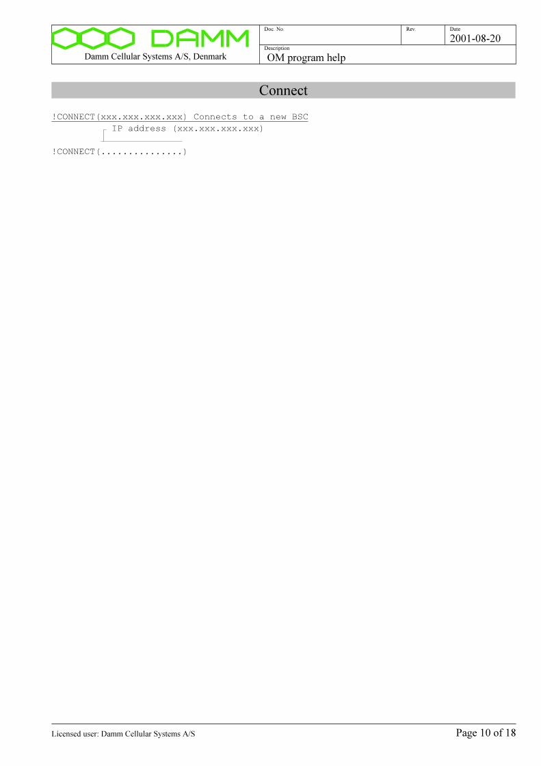
Damm Cellular Systems A/S, Denmark OM program help
Doc. No. Rev. Date
Description
2001-08-20
Connect
!CONNECT(xxx.xxx.xxx.xxx) Connects to a new BSC
IP address (xxx.xxx.xxx.xxx)
!CONNECT(...............)
Page 10 of 18Licensed user: Damm Cellular Systems A/S

Damm Cellular Systems A/S, Denmark OM program help
Doc. No. Rev. Date
Description
2001-08-20
Disconnect
!DISCONNECT Disconnects from the current BSC
!DISCONNECT
Page 11 of 18Licensed user: Damm Cellular Systems A/S
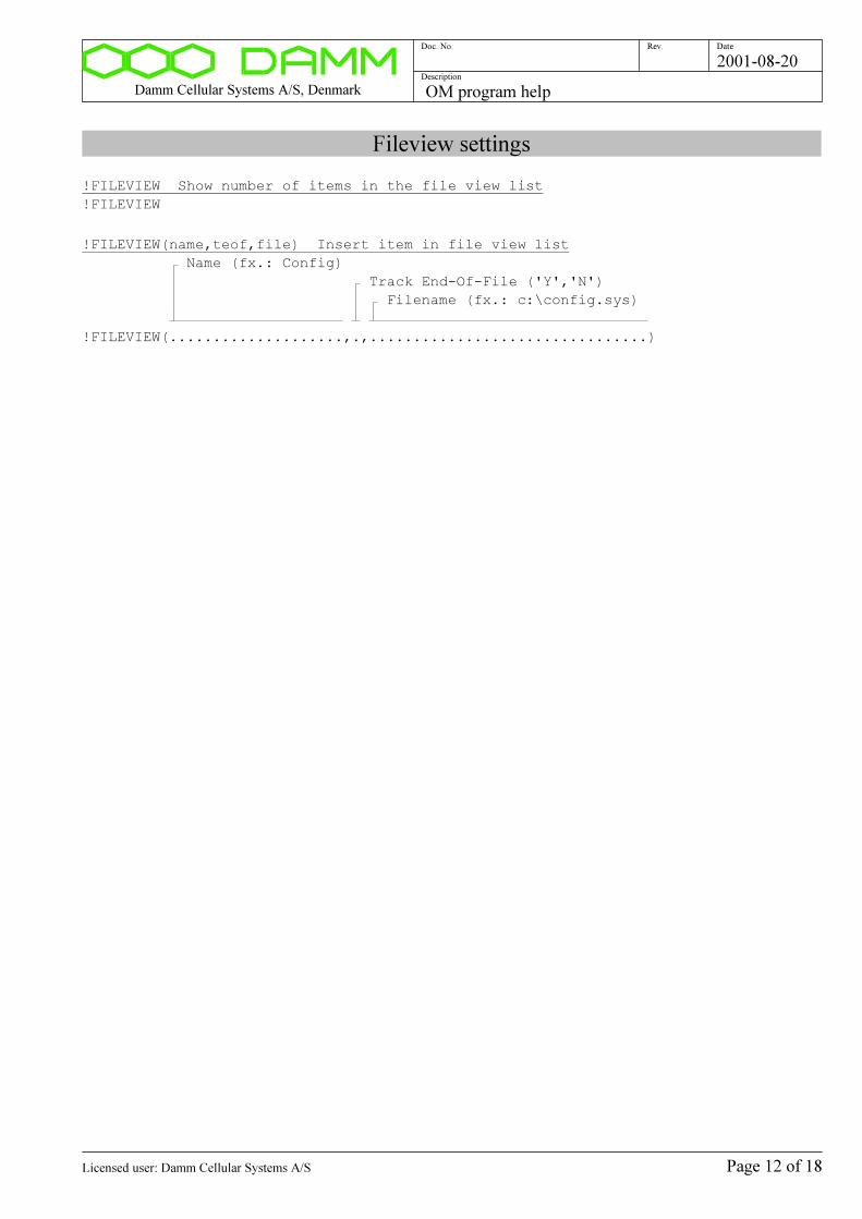
Damm Cellular Systems A/S, Denmark OM program help
Doc. No. Rev. Date
Description
2001-08-20
Fileview settings
!FILEVIEW Show number of items in the file view list
!FILEVIEW
!FILEVIEW(name,teof,file) Insert item in file view list
Name (fx.: Config)
Track End-Of-File ('Y','N')
Filename (fx.: c:\config.sys)
!FILEVIEW(....................,.,................................)
Page 12 of 18Licensed user: Damm Cellular Systems A/S
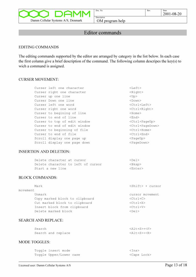
Damm Cellular Systems A/S, Denmark OM program help
Doc. No. Rev. Date
Description
2001-08-20
Editor commands
EDITING COMMANDS
The editing commands supported by the editor are arranged by category in the list below. In each case
the first column give a brief description of the command. The following column descripes the key(s) to
wich a command is assigned.
CURSER MOVEMENT:
Curser left one character <Left>
Curser right one character <Right>
Curser up one line <Up>
Curser Down one line <Down>
Curser left one word <Ctrl+Left>
Curser right one word <Ctrl+Right>
Curser to begining of line <Home>
Curser to end of line <End>
Curser to top of edit window <Ctrl+PageUp>
Curser to end of edit window <Ctrl+PageDown>
Curser to beginning of file <Ctrl+Home>
Curser to end of file <Ctrl+End>
Scroll display one page up <PageUp>
Scroll display one page down <PageDown>
INSERTION AND DELETION:
Delete character at cursor <Del>
Delete character to left of cursor <Bksp>
Start a new line <Enter>
BLOCK COMMANDS:
Mark <Shift> + cursor
movement
Unmark cursor movement
Copy marked block to clipboard <Ctrl+C>
Cut marked block to clipboard <Ctrl+X>
Insert block from clipboard <Ctrl+V>
Delete marked block <Del>
SEARCH AND REPLACE:
Search <Alt+S>+<F>
Search and replace <Alt+S>+<R>
MODE TOGGLES:
Toggle insert mode <Ins>
Toggle Upper/Lower case <Caps Lock>
Page 13 of 18Licensed user: Damm Cellular Systems A/S
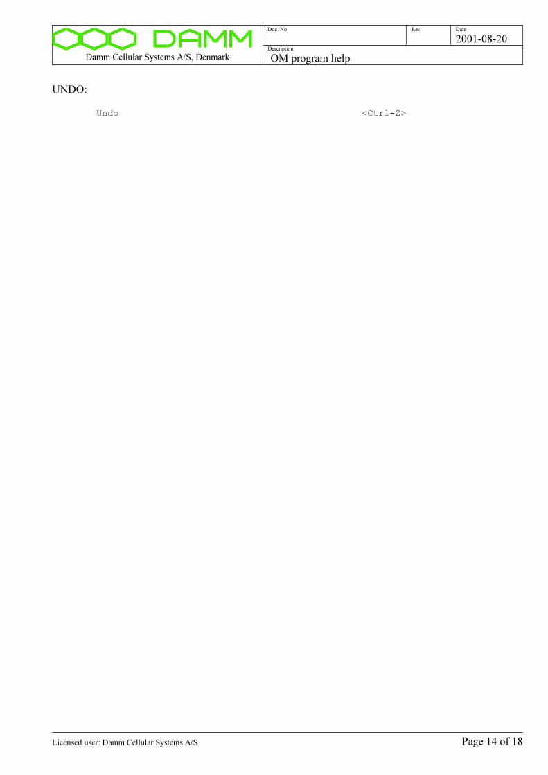
Damm Cellular Systems A/S, Denmark OM program help
Doc. No. Rev. Date
Description
2001-08-20
UNDO:
Undo <Ctrl-Z>
Page 14 of 18Licensed user: Damm Cellular Systems A/S
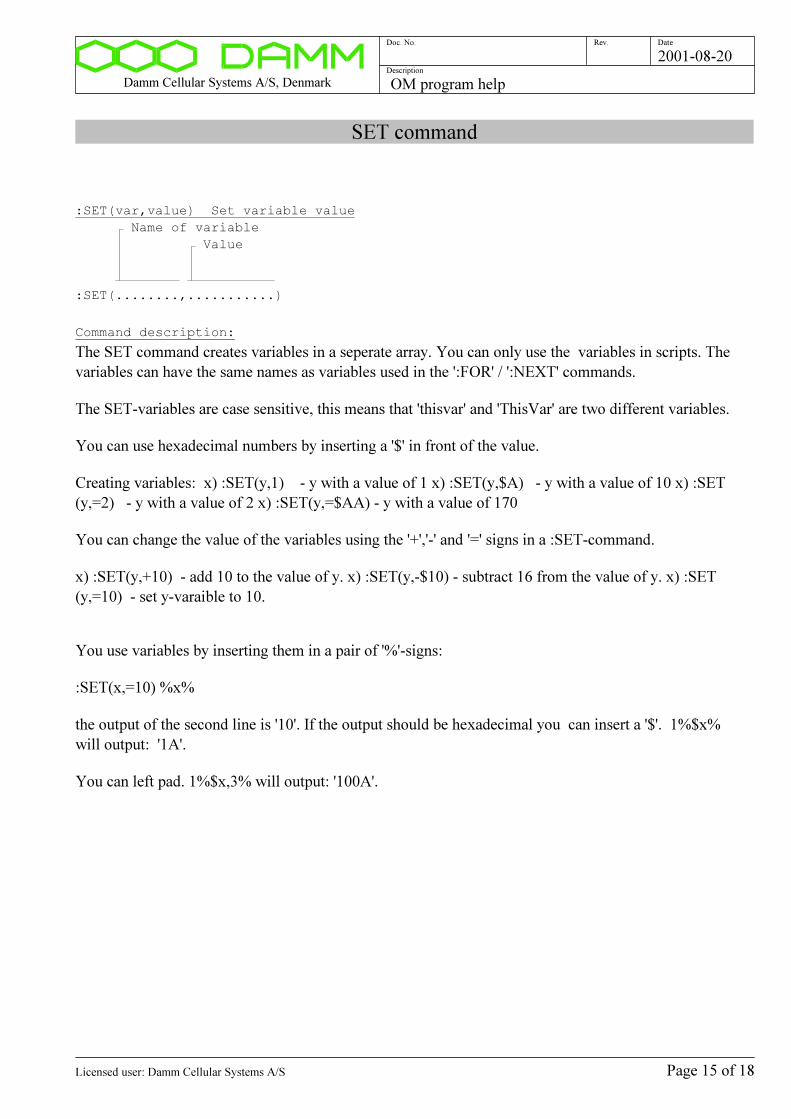
Damm Cellular Systems A/S, Denmark OM program help
Doc. No. Rev. Date
Description
2001-08-20
SET command
:SET(var,value) Set variable value
Name of variable
Value
:SET(........,...........)
Command description:
The SET command creates variables in a seperate array. You can only use the variables in scripts. The
variables can have the same names as variables used in the ':FOR' / ':NEXT' commands.
The SET-variables are case sensitive, this means that 'thisvar' and 'ThisVar' are two different variables.
You can use hexadecimal numbers by inserting a '$' in front of the value.
Creating variables: x) :SET(y,1) - y with a value of 1 x) :SET(y,$A) - y with a value of 10 x) :SET
(y,=2) - y with a value of 2 x) :SET(y,=$AA) - y with a value of 170
You can change the value of the variables using the '+','-' and '=' signs in a :SET-command.
x) :SET(y,+10) - add 10 to the value of y. x) :SET(y,-$10) - subtract 16 from the value of y. x) :SET
(y,=10) - set y-varaible to 10.
You use variables by inserting them in a pair of '%'-signs:
:SET(x,=10) %x%
the output of the second line is '10'. If the output should be hexadecimal you can insert a '$'. 1%$x%
will output: '1A'.
You can left pad. 1%$x,3% will output: '100A'.
Page 15 of 18Licensed user: Damm Cellular Systems A/S
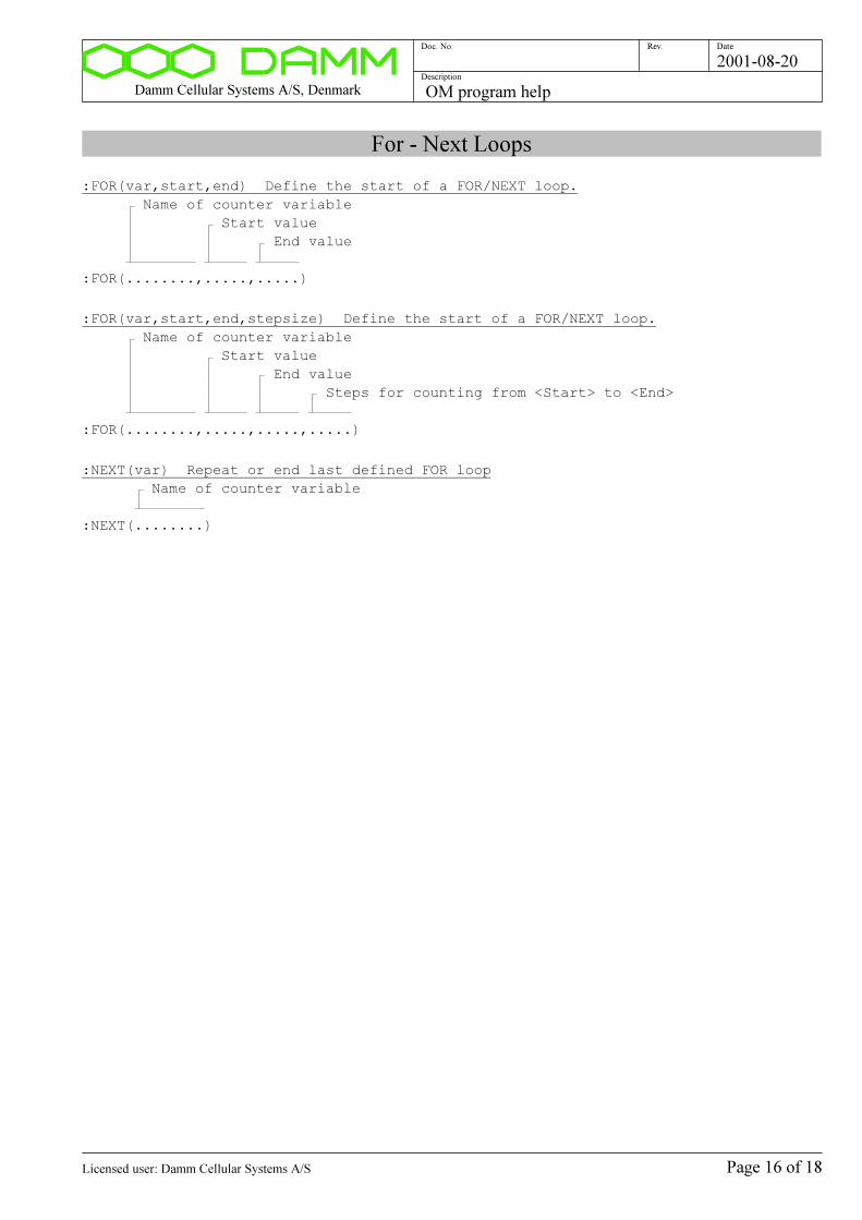
Damm Cellular Systems A/S, Denmark OM program help
Doc. No. Rev. Date
Description
2001-08-20
For - Next Loops
:FOR(var,start,end) Define the start of a FOR/NEXT loop.
Name of counter variable
Start value
End value
:FOR(........,.....,.....)
:FOR(var,start,end,stepsize) Define the start of a FOR/NEXT loop.
Name of counter variable
Start value
End value
Steps for counting from <Start> to <End>
:FOR(........,.....,.....,.....)
:NEXT(var) Repeat or end last defined FOR loop
Name of counter variable
:NEXT(........)
Page 16 of 18Licensed user: Damm Cellular Systems A/S
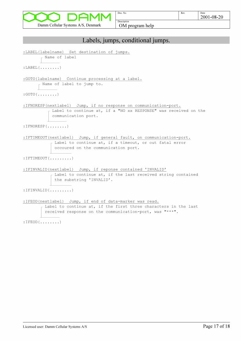
Damm Cellular Systems A/S, Denmark OM program help
Doc. No. Rev. Date
Description
2001-08-20
Labels, jumps, conditional jumps.
:LABEL(labelname) Set destination of jumps.
Name of label
:LABEL(........)
:GOTO(labelname) Continue processing at a label.
Name of label to jump to.
:GOTO(........)
:IFNORESP(nextlabel) Jump, if no response on communication-port.
Label to continue at, if a "NO xx RESPONSE" was received on the
communication port.
:IFNORESP(........)
:IFTIMEOUT(nextlabel) Jump, if general fault, on communication-port.
Label to continue at, if a timeout, or out fatal error
occoured on the communication port.
:IFTIMEOUT(.........)
:IFINVALID(nextlabel) Jump, if reponse contained 'INVALID'
Label to continue at, if the last received string contained
the substring 'INVALID'.
:IFINVALID(.........)
:IFEOD(nextlabel) Jump, if end of data-marker was read.
Label to continue at, if the first three characters in the last
received response on the communication-port, was "***".
:IFEOD(........)
Page 17 of 18Licensed user: Damm Cellular Systems A/S
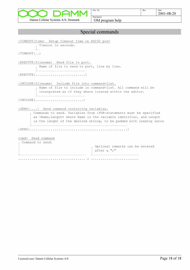
Damm Cellular Systems A/S, Denmark OM program help
Doc. No. Rev. Date
Description
2001-08-20
Special commands
:TIMEOUT(time) Setup timeout time on RS232 port
Timeout in seconds.
:TIMEOUT(..)
:EXECUTE(filename) Send file to port.
Name of file to send to port, line by line.
:EXECUTE(..........................)
:INCLUDE(filename) Include file into command-list.
Name of file to include in command-list. All command will be
interpreted as if they where located within the editor.
:INCLUDE(.........................)
:SEND(....) Send command containing variables.
Commands to send. Variables from :FOR-statements must be specified
as %Name,Length% where Name is the variable identifier, and Length
is the lenght of the desired string, to be padded with leading zeros
:SEND(...................................................)
<cmd> Send command
Command to send.
Optional remarks can be entered
after a ";"
................................... ; .........................
Page 18 of 18Licensed user: Damm Cellular Systems A/S