mahaweli ganga development sri lankamahaweli.gov.lk/en/pdf/library/mahaweli ganga development sri...
TRANSCRIPT

MAHAWELI GANGA DEVELOPMENT
SRI LANKA
SUMMARY REPORTS
ON
PROJECTS
PREPARED BY
MAHAWELI DEVELOPMENT BOAD
NOVEMBER 197

Contents
INTRODUCTION ............................................................................................................................................. 1
1.1 The Mahaweli Ganga .......................................................................................................................... 4
1.2 The Master Plan .................................................................................................................................. 4
1.3 Implementation .................................................................................................................................. 5
1.4 Project Components ........................................................................................................................... 7
1.5 Basis of Report .................................................................................................................................... 9
1.6 Cost and Benefits. ............................................................................................................................. 10
1.7 Conclusions ....................................................................................................................................... 10
2. VICTORIA RESERVOIR PROJECT ............................................................................................................... 12
2.1 Purpose of Scope .............................................................................................................................. 12
2.2 Location ............................................................................................................................................. 12
2.3 Basic Features ................................................................................................................................... 12
2.4 Geology ............................................................................................................................................. 13
2.5 Irrigation Development ..................................................................................................................... 13
2.6 Flowage Damage ............................................................................................................................... 14
2.7 Cost Estimates ................................................................................................................................... 14
3. MORAGAHAKANDE PROJECT .................................................................................................................. 15
3.1 Purpose and Scope ............................................................................................................................ 15
3.2 Previous Studies ................................................................................................................................ 15
3.3 Location and Access .......................................................................................................................... 16
3.4 Basic features .................................................................................................................................... 16
3.5 Dam and Reservoir ............................................................................................................................ 16
3.6 Geology ............................................................................................................................................. 17
3.7 Irrigation ............................................................................................................................................ 17
3.8 Cost Estimates ................................................................................................................................... 17
4.MADURA OYA – HYDRO PROJECT ............................................................................................................ 18
5. TALDENA HYDRO UNIT ............................................................................................................................ 21
6. RANDENIGALA RESERVOIR PROJECT ....................................................................................................... 22
6.1 Purpose and Scope ............................................................................................................................ 22
6.2 Location ............................................................................................................................................. 22

6.3 Basic Features ................................................................................................................................... 23
6.4 Dam Reservoirs and Hydropower Stations ....................................................................................... 23
6.5 Geology ............................................................................................................................................. 23
7. UPPER UMA OYA HYDRO UNIT ............................................................................................................... 25
8. LOWER UMA OYA HYDRO UNIT .............................................................................................................. 26
9. KALU GANAGA HYDRO UNIT ................................................................................................................... 28
10. PALLEWELA HYDRO UNIT ...................................................................................................................... 30
11. HEEN GANGA HYDRO UNIT ................................................................................................................... 32
12. ROTALAWELA HYDRO UNIT .................................................................................................................. 34
13. KOTMALE PROJECT ............................................................................................................................... 35
13.1 Purpose and Scope .......................................................................................................................... 35
13.2 Location ........................................................................................................................................... 35
13.3 Basic Features ................................................................................................................................. 35
13.4 Dam, Tunnel and Power Station ..................................................................................................... 35
13.5 Geology ........................................................................................................................................... 36
13.6 Present Position of Studies ............................................................................................................. 36
13.7 Benefits ........................................................................................................................................... 37
13.8 Cost Estimates ................................................................................................................................. 37
14. ULHITIYA OYA RESERVOIR ..................................................................................................................... 38
15. RIGHT BANK TRANSBASIN [R.B] CANAL ................................................................................................ 40
16. TRANSBASIN CANAL .............................................................................................................................. 41
17. NORTH CENTRAL PROVINCE TRANSBASIN CANAL ............................................................................... 43
18. NORTH CENTRAL PROVINCE TRANSBASIN CANAL ............................................................................... 44
19. MALWATTU OYA RESERVOIR ................................................................................................................ 46
20. YAN OYA RESERVOIR ............................................................................................................................. 47
21. OTHER SERVICE RESEROIRS UNDER THE N.C.P. CANAL ........................................................................ 47
21.2 Kitagala Reservoir ........................................................................................................................... 48
21.3 Kanagarayan Aru Reservoir ............................................................................................................. 48
21.4 Parangi Aru Reservoir ..................................................................................................................... 48
21.5 Pali Aru Reservoir ............................................................................................................................ 49

INTRODUCTION
1.1 The Mahaweli Ganga
Mahaweli Ganga rises in the central mountains at an elevation of 8,000ft. above M.S.L. and
flows down to Koddiar Bay in the east coast of the Island south of Trincomalee. The river is
about 207 miles long and has a drop of 8,000ft. The mean annual runoff of the river is 7.2
million acre feet. This is over 20℅ of the total runoff of all the rivers in the Island.
The total drainage area of the river 4,034 sq. miles which is about 16℅ of the total land area of
the Island. The mean annual precipitation in the area is high being 75 to 217 inches in the upper
820 sq. miles of the catchment which lie in the wet zone and 65 to 75 inches in the lower
reaches of 3,214 sq. miles which lie in the dry zone.
In spite of the favorable rainfall and soil conditions in the basin, the large hydropower potential
due to the steep radiant of the river bed in the upper reaches and the high runoff in the river
available for irrigation development, the Mahaweli remains one of the least exploited rivers in
the Island. About 72.5℅ of the land in the basin suitable for agricultural development is still in
jungle. And the utilization of the river runoff for irrigation is less than 10℅. The first
hydropower development has just been completed on the project out of a total potential
estimated at about 50℅ of the total available hydropower potential of all the rivers in the
country.
1.2 The Master Plan
A UNDP/ FAO team with Sri Lankan counterparts carried out a survey of the Irrigation and
Hydro – Power potential of the Mahaweli Ganga and the adjoining river basins during the four
year period 1965 to 1968 and formulated a Master Plan for the development of the available
resources. The Master Plan is described in the three volumes on ‘Mahaweli Ganga Irrigation
and Hydro – Power Survey’ – FAO – Rome 1969.
The Plan envisages the development under irrigation of 900,000 acres of land and generation of
2,037 million kilowatt hours of hydro electric energy from an installed capacity of 507
megawatts. The capital cost estimated in 1968 was Rs. 5,583 million, excluding cost of activities
resulting directly from the project, but having their own economic justification, estimated at Rs.
1,120 million. In view of the large magnitude of the work and investment involved, the Master
Plan was divided into three phases for purposes of implementation . the feasibility of three
projects in Phase I was carried out in grater detail by the same team and described in Vol. ii of
the final report.
To develop the natural yield of the Mahaweli Ganga and the adjoining Maduru Oya. 15
reservoirs have been proposed – 4 on the Mahaweli 10 on its tributaries and one on the
Maduru Oya. Thirteen of these reservoirs are multi – purpose units for development of
hydropower as well. [ 2 of which will produce hydropower for short periods only when the
water level is high], and the other two are purely for irrigation purposes. These reservoirs will
regulate annually 4.75 million acre feet from the Mahaweli and its tributaries and 0.14 million
acre feet from the Maduru Oya for development purposes. This is far in excess of the irrigation
needs of the available lands in these two basins. The surplus water will be diverted to the
adjoining north central region to develop 324 thousand acres of land. These lands are located in
six of the major river basins in that region. Seven service reservoirs are proposed in addition to
18 existing major tanks in this region, to store and regulate the diverted water, in addition to
0.7 million acre feet of runoff from their own catchments. A list of the reservoirs with their
parameters is given in Annex 1 and Short notes on the reservoirs and Transbasin canals are
contained in Page 9 – 55.
The conveyance of the diverted flow from the major reservoirs to the proposed service
reservoirs and existing major tanks for issue to the fields is effected is effected by 4 Transbasin
canals.
The regulated flow will provide irrigation facilities to 900,000 acres of land, which comprises all
available suitable land in the Mahaweli and Maduru Oya basins and 430,000 acres of land in the
north central region. About 246,000 acres of the land presently cultivated under irrigation will
receive supplementary water supply for the continuous cultivation of two crops an year. The
other 654,000 acres are new lands presently in jungle.
The lands to be benefited are grouped under 14 irrigation systems designated A to M, Land Use
surveys indicate that more than 50℅ of the land proposed for development is suitable for the
cultivation of a variety of high value upland crops other than rice. The extents under each of the
14 irrigation systems and proposed crop rotation are given in Annex 2.
Phase I of the Master Plan for which feasibility studies have been prepared by the UNDP/ FAO
team has been sub – divided into three projects. The sub division of Phases ii and iii was left to
a later stage when execution of the projects is taken up for consideration. Each of the projects
in Phase I, and Phases II and III, were individually evaluated and found to be economically
viable. Each project can be constructed in a period of 4 to 60 years. The entire Master Plan was
phase for stepwise implementation over a time period of 30 years.
1.3 Implementation
Execution of Project I of Phase I was commenced in 1970 and scheduled for completion in 1978.
It comprises of a barrage across the Mahaweli Ganga at Polgolla to divert a maximum of 2,000
cusecs through a 5 Mile long pressure tunnel to a power Plant of 40 MW installed capacity
situated in the adjacent Amban Ganga basin, The tail race water flows down a tributary of the

Amban Ganga into a reservoir at Bowatenna formed by a concrete dam across the river, which
diverts a part of the flows into the adjacent Kala Oya basin, through a 4 mile long tunnel and a
Transbasin canal into Kalawewa and reservoirs. The rest of the diverted water along with the
natural flow of the Amban Ganga. Is sent down the river to be diverted at the existing Elahere
and Angamedilla diversion weirs into existing conveyance canals. The total extent of land
benefited by Project I is 132,000 acres of existing fileds and 91,000 acre of new lands. The
headworks including the tunnel and the P.K. Transbasin canal have been completed and
development of the new lands is in progress. The expenditure incurred so for on the Headworks
is Rs. 332 million of which the foreign exchange component was financed by a World Bank loan
and credit of US $ 29 million. The work on the irrigation facilities to be provided to new lands
benefited under Project I is estimated to cost Rs. 815 million. Part of this is financed by a IDA
Credit loan of 29 million. The work on the irrigation facilities to be provided to new lands
benefited under Project I is estimated to cost Rs. 815 million. Part of this financed by a IDA
Credit loan of $ 42.2 million from the IDA. Netherlands. Canada. USA and UK.
The other two projects identified in priority under Phase I of the Master Plan on which more
comprehensive feasibility studies had been made by the UNDP/ FAO team with Ceylonese
counterparts, were the Victoria – Minipe Diversion Complex and the Moragahakanda
Multipurpose unit.
It has now been decided by the Sri Lanka Government to accelerate the pace of development
with a view to complete all works envisaged in the Master Plan in five years. For this purpose,
all works [other than Project 1 which is nearing completion], are grouped as 12 projects, as
indicated below which can be studies an d executed as such.
The first two are Projects 2 and 3 according to priorities in phase I in the Master Plan. Projects
3 and 4 are items in Phase II.
Project No
Name of Project and major components Estimated total cost Rs. Million
1 Victoria Multipurpose Complex 2,025
2 Moragahakanda Multipurpose Complex 1,070
3 Maduru Oya Reservoir Complex 1,180
4 Taldena Multipurpose Complex 380
5 Kotmale Multipurpose Complex 1,035
6 Kalu Ganga Reservoirs Complex 800
7 Rotalawela Reservoir Complex 320
8 Pallewela Multipurpose Complex 695
9 Malwatu Oya Reservoir Complex 335
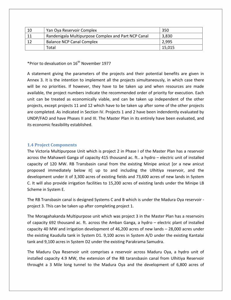
10 Yan Oya Reservoir Complex 350
11 Randenigala Multipurpose Complex and Part NCP Canal 3,830
12 Balance NCP Canal Complex 2,995
Total 15,015
*Prior to devaluation on 16th November 1977
A statement giving the parameters of the projects and their potential benefits are given in
Annex 3. It is the intention to implement all the projects simultaneously, in which case there
will be no priorities. If however, they have to be taken up and when resources are made
available, the project numbers indicate the recommended order of priority for execution. Each
unit can be treated as economically viable, and can be taken up independent of the other
projects, except projects 11 and 12 which have to be taken up after some of the other projects
are completed. As indicated in Section IV. Projects 1 and 2 have been indendently evaluated by
UNDP/FAO and have Phases II and III. The Master Plan in its entirely have been evaluated, and
its economic feasibility established.
1.4 Project Components
The Victoria Multipurpose Unit which is project 2 in Phase I of the Master Plan has a reservoir
across the Mahaweli Ganga of capacity 415 thousand ac. ft.. a hydro – electric unit of installed
capacity of 120 MW. RB Transbasin canal from the existing Minipe anicut [or a new anicut
proposed immediately below it] up to and including the Ulhitiya reservoir, and the
development under it of 3,300 acres of existing fields and 73,600 acres of new lands in System
C. It will also provide irrigation facilities to 15,200 acres of existing lands under the Minipe LB
Scheme in System E.
The RB Transbasin canal is designed Systems C and B which is under the Madura Oya reservoir -
project 3. This can be taken up after completing project 1.
The Moragahakanda Multipurpose unit which was project 3 in the Master Plan has a reservoirs
of capacity 692 thousand ac. ft. across the Amban Ganga, a hydro – electric plant of installed
capacity 40 MW and irrigation development of 46,200 acres of new lands – 28,000 acres under
the existing Kaudulla tank in System D1. 9,100 acres in System A/D under the existing Kantalai
tank and 9,100 acres in System D2 under the existing Parakrama Samudra.
The Maduru Oya Reservoir unit comprises a reservoir across Maduru Oya, a hydro unit of
installed capacity 4.9 MW, the extension of the RB taransbasin canal from Ulhitiya Reservoir
throught a 3 Mile long tunnel to the Madura Oya and the development of 6,800 acres of

existing lands and 95,000 acres of new land, in System B [out of a total of 118,100 acres]. The
balance 23,200 acres in System B is provided for under project 4 – Taldena Multipurpose Unit.
The execution of this project – No. 3 could be taken up after project I.
The Taldena Multipurpose Unit consists of the Taldena reservoir across the Badulu Oya. A hydro
- electric plant of installed capacity 14.5 MW and development of the balance 23,200 acres in
System B. The tailrace water from the hydro – electric plant will be led down the Loggala into
the RB Transbasin canal and them to Maduru Oya reservoir from which the irrigation
requirements will be supplied. The execution of this project No. 4 could be taken up after
Project 3.
The Kotmale Multipurpose Unit comprises a reservoir across the Kotmale Oya and hydro –
electric plant. The tailrace water will flow down the river and part of it diverted at Polgolla. It
will be re – regulated at Moragahakanda and used to provide more assured irrigation
development of existing lands in System below it. When the NCP Canal is constructed, the
additional 300,000 ac.ft. that can be regulated at Moragahakanda will be used for irrigating
lands in the North Central region. The immediate benefits will be from power generation with
an installed capacity of 150 MW. The work can commence without delay as specification
documents and plans have been prepared by a firm of Indian Consultants, and will be finalized
and made available by the end of this year.
The Kalu Ganga Reservoir Unit comprises a reservoir across Kalu Ganga, a hydro – electric plant
and irrigation development of 500 acres of existing fields and 8,200 acres of new lands in
System F directly under it. The excess water regulated as the reservoir can be sent down the
river to be picked up at the diversion anicut to be constructed at Kandakadu across the
Mahaweli Ganga to benefit 14,000 acres of exiting fields and 36,000 acres out of 100,000 acres
of new lands in System A which is in the Mahaweli Delta. The cost of construction of the anicut
and irrigation development of the 36,000 acres are provided for in the construction cost. The
development of the balance extent of 54,000 acres in System A are provided for under projects
7 and 8 [as 9,100 acres have been included from development in project 2].
The Rotalawela Reservoir is an irrigation reservoir that will be constructed for the purpose of
supplementing the water requirements of lands in System A. The unit comprises a reservoir
across the Mahaweli Ganga and development of 18,000 acres of land under the Kandakadu
anicut in System A.
The Pallewela Multipurpose Unit consists of the Pallewela reservoir across the Loggal Oya, a
hydro – electric plant and development of 36,900 acres of land [in System A under the
Kandakadu anicut]. The water is sent down the RB Transbasin canal thus releasing an

equivalent quantity of water from the Victoria Reservoir for conveyance along the Mahaweli to
the diversion at Kandakadu anicut.
The Malwatu Oya Reservoir comprises a reservoir for the development of 19,300 acres of
existing land and 9,000 acres of new land with water from its own catchment. The irrigation
requirements of the 19,300 acres of existing lands is sent down the river and diverted from an
existing anicut at Tekkam. To the fields under Giants Tank. When the Malwatu Oya and the
reservoir is augmented by the NCP Capital, an additional 7,300 acres of new lands can be taken
up for irrigation development.
The Yan Oya Reservoir Unit comprises a reservoir across the Oya for the development of 3000
acres of existing lands and 16,000 acres of new lands directly under it. After it is augmented
from the NCP Canal, an additional extent of 8,900 acres of new lands can be taken up for
irrigation development.
The Randenigala Multipurpose Unit and part of the NCP Canal 67 miles in length taking off from
Moragahakanda Reservoir will irrigate 78,000 acres of new lands in System I under Kapirigama
Reservoir to be constructed and Malwatu Oya Reservoir, and 8,900 acres in System M under
the Yan Oya Reservoir. There will also be an extent of 22,900 of existing land in System.
A LB Canal under the Minipe anicut will be constructed down to Kaudulla in order to take up
the irrigation commitments under Moragahakanda Reservoir which will be exclusively
operated for the supply of the NCP Canal.
The balance NCP Canal complex will comprise of extension to the NCP Canal up to 103 miles, for
the development of 27,600 acres of existing fields and 120,700 acres of new lands under
Kitagala Reservoir System L. Kanagarayan Aru System K and the Parangi Aru and Pali Aru System
J. For this purpose, additional reservoirs will be constructed at Upper and Lower Uma Oya to
relieve part of the commitments of Victoria – Randenigala cascade on the Rigth Bank for
utilization on the Left Bank Canal. The Left Bank Canal will be augmented by a reservoir to be
built on the Heen Ganga. A pumping station will be provided to pump the excess water
available in the LB Canal into the NCP at a point below the Amban Ganga crossing.
1.5 Basis of Report
This report is based on comprehensive studies carried out by UNDP/FAO. Additional
investigations were subsequently carried out for the design of the Kotmale Hydro Unit under
the direction of the Water and Power Development Consultancy Services Ltd. [India], and the
specification documents and plans are expected to be ready by the end of 1977.

Additional topographical investigations are being carried out for the Moragahakanda and
Ulhitiya Reservoirs, the Minipe RB Canal, the NCP Canal and the seven service reservoirs under
it. Topographical and geological investigations for the Victoria projects have now commenced.
1.6 Cost and Benefits.
The estimated capital cost of the Works is as per the Cost Estimates indicated in the UNDP/ FAO
Final Report, increased three – fold to provide for current prices.
After the adjustment of the parity rates in the 1978 budget proposals, and the abolition of
Foreign Exchange Entitlement Certificates the cost estimate will need to be updated. It is
expected that the estimated cost of Rs. 15,015 million will increase by 100℅ on the foreign
component [of about 40℅] and 15℅ in the local component [of about 60℅].
Two major problems facing the country are unemployment and the high cost of imports of
agricultural products. Settlement of colonists on lands provided with irrigation facilities is still
the cheapest form of remunerative employment generation. The implementation of the
schemes in the Mahaweli Master Plan. In the shortest possible time. Will provide employment
during construction for about 800,000 persons. On completion of the Works, about 225,000
landless farmer families will be settled on the lands. Thus providing employment for about a
million people in agricultural and allied pursuits. ‘
The present import of Agricultural produce inclusive of rice costs the country over 2000 million
rupees of foreign exchange per year. Most of this agricultural produce can be grown locally and
with the implementation of the Mahaweli Master Plan in 5 – 6 years will make the country self
– sufficient in food.
The net value of agricultural produce grown under the projects, it estimated at over R. 1900
million per year with mixed cropping, growing high value crops on well drained soils and rice on
bottom lands.
The value of the hydropower generated from multi – purpose projects at 20 cts. Per KWH [as
compared to about 35 cts. Per unit of thermal power] will be Rs. 325 million.
1.7 Conclusions
Comprehensive studies by the UNDP/FAO Which had taken into account previous studies
carried out by the Hunting Survey Corporation of Canada and the United States Operations
Mission. Have established the economic feasibility of implementing the projects in the
Mahaweli Master Plan.

There is sufficient skilled personnel in the country, who are competent to undertake work on
all the Projects, with foreign technical assistance in specialized fields.
The execution of this Project in a period of 30 years as en visage in the Master Plan , will not
have the desired impact on the economy of this country, an d will not be solve the serious
unemployment and food shortage problems.
The Mahaweli Master Plan in divided into 12 viable Projects, which can be undertaken
simultaneously and completed in 5 to 6 years, provided the necessary resources are available.
The Government is committed to provide the social infra – structure requirements such as
health, education, transport facilities in addition to agricultural inputs to achieve maximum
production.

2. VICTORIA RESERVOIR PROJECT
2.1 Purpose of Scope
The Victoria Reservoir Project comprises the Victoria Reservoir formed by the construction of
an arch gravity dam across the Mahaweli Ganga, a pressure tunnel leading to the power station
, the surge shaft, a power plant and the irrigation system to develop under irrigation 73,600
acres of new land and 3,300 acres of existing fields on the Right Bank of the Mahaweli Ganga.
The construction work on Project I Phase I as formulated by the UN DP/FAO team in the
Master Plan was commenced in 1970 and the full development under this project is expected
to be completed by about 1979. The Victoria Reservoir Project is the second project in Phase I.
2.2 Location
The dam is located across the Mahaweli Ganga immediately upstream of the Victoria falls
rapids at about 130 miles from the river mouth. The site is about 72 aerial miles east of
Colombo. 4 miles from Teldeniya. There is a good from Colombo to Teldeniya, distance about
84 miles. The present access from Teldeniya to the site is along the jungle tract, 4 miles long.
The nearest railway present access from Teldeniya to the site is along jungle tract, 4 miles long.
The nearest railway station is Kandy. 72 miles from Colombo and 12 miles from Teldeniya.
2.3 Basic Features
The catchment area of the river above the proposed damsite is 730 sq. miles, Upstreamof this
site. The Polgolla dam. For the diversion of a maximum flow of 2,000 cusecs, has been
constructed and is in operation. Detailed investigations and feasibility studies for the
construction of a dam across the Kotmale Oya. a major upper right bank tributary of the
Mahaweli Ganga are being prepared and are in its final stages of completion.
The drainage area of the proposed reservoir is situated in the central hills ranging up to bout
8,000ft.
The long term mean annual runoff at the dam site is 2,430 thousand acre feet of which 1,100
thousand ac.ft. presently being diverted at Polgolla.
Dam and Reservoir
The dam is located in the deep valley of the Mahaweli Ganga just above the Victoria Falls
rapids. The engineering geologic conditions of the dam site are favourable. The foundation will
be of hard. Slightly fractured gneiss deposited at depths 8 to 17ft. in fragmented and
weathered rock.
The shape of the valley and the geologic conditions are favourable for the construction of an
arch slightly fractured granulated gneiss deposited at depths 8 to 17ft. in fragmented and

weathered rock. The shape of the valley and the geologic conditions are favourable for the
construction of an arch dam. An arch gravity dam of triangular section and having a vertical
upstream face is proposed. It will have a maximum height of 338 feet and the length along the
crest will be 1400ft. The middle part of the dam forms the spillway, which will be furnished with
4 radial gates. 50ft. wide and 30ft. high. The spillway will reduce flood peak of 0.1℅ frequency
of 225,000 cusecs to 175,000 cusecs with a flood life of 7ft. above the normal water surface
elevation of 1410. MSL.
The gross capacity of the reservoir is 415 thousand ac.ft. active capacity 390 thousand ac. ft.
which will have an annual regulated discharge of 926 thousand ac.ft. for irrigation releases.
During ‘Shut down’ period and for emergency use, an under sluice of size 7 x 7 having a
discharge capacity of about 1200 cusecs. Will be provided.
Hydro – Electric Station
The Hydro – electric station to be located on the right bank of the river will be equipped with
four generators having a total capacity of 120 MW at a design discharge of 2740 causes and a
net mean head ft. Firm power capacity is 54 MW. Annual firm energy output is 469 million KWH
and average energy output is 629 million KWH.
Conveyance of water to the hydro – electric station is provided along a pressure tunnel
14,720ft. long, lined with concrete which is capable of a maximum discharge of 2740 cusecs,
which has an internal diameter of 21 feet. From the tunnel outlet to the turbine steel penstocks
are laid along the slopes of the river valley.
2.4 Geology
Engineering geologic conditions at the damsite; and along the tunnel trace are favourable. The
dam foundation will be on hard, slightly fractured granulites and gneisses deposited at depths
of 8 – 17 feet under fragmented and highly weathered rocks. The tunnel trace runs through a
mountain mass composed of practically un weathered gneisses, and granulities. Only at its end,
the trace crosses fresh crystalline limestones. The area under the penstock lines and the power
house feldspathic gneisses. Geomorphologic and geologic conditions of the reservoir bed
exclude water loss through its periphery. Just above the confluence of Mahaweli and Hulu
Ganga, where highly karstic cavernous limestones are encounted. An underground connection
from the Mahaweli to the Hulu Gangais possible. However. This does not seem to extend
beyond the reservoir bed boundaries. This has to be checked by further geological investigation
during the final designs stage.
2.5 Irrigation Development
Releases from the reservoir will flow down the Mahaweli Ganga to the site of the Minipe
anicut where a new diversion structure about 500ft. below the existing anicut will be
constructed. A new head sluice on the right bank of the river will control the issues to the
proposed Right Transbasin canal to benefit 73,600 acres of new lands and 3,300 acres of
existing fields in the Right Bank of the Mahaweli Ganga. On the left bank the water will be
diverted along the existing Minipe L.B. canal to provide supplementary irrigation to 5,200 acres
of existing fields.
2.6 Flowage Damage
At the normal water surface elevation of 1410 MSL the reservoir submerges an area of 4,550
acres. Partly developed and partly jungle land. The Teldeniya town too will be submerged and
provision is made in the cost estimates for the construction of a new town.
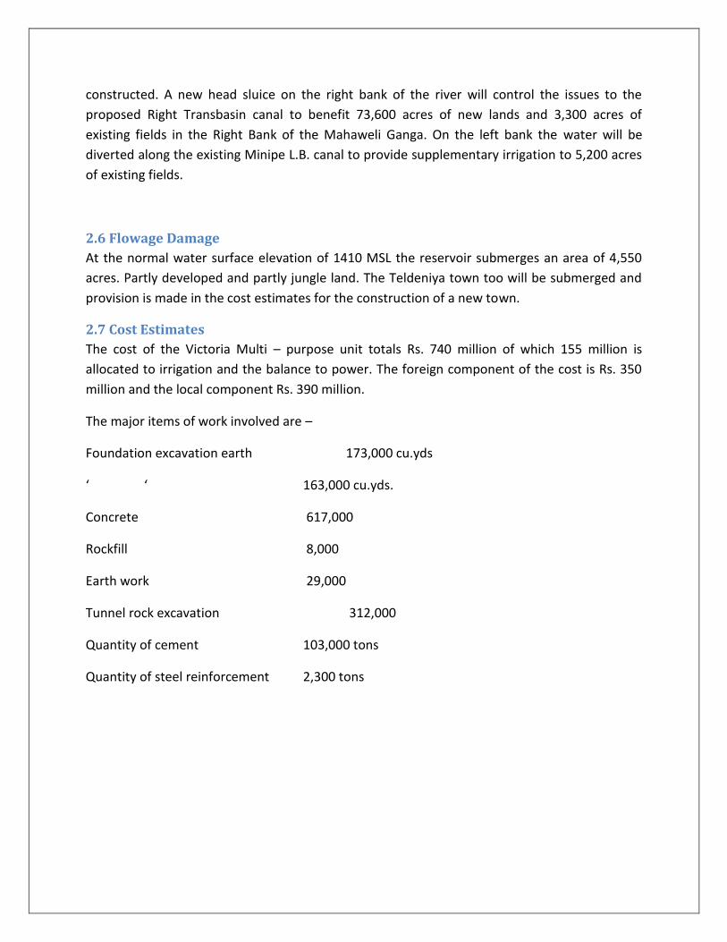
2.7 Cost Estimates
The cost of the Victoria Multi – purpose unit totals Rs. 740 million of which 155 million is
allocated to irrigation and the balance to power. The foreign component of the cost is Rs. 350
million and the local component Rs. 390 million.
The major items of work involved are –
Foundation excavation earth 173,000 cu.yds
‘ ‘ 163,000 cu.yds.
Concrete 617,000
Rockfill 8,000
Earth work 29,000
Tunnel rock excavation 312,000
Quantity of cement 103,000 tons
Quantity of steel reinforcement 2,300 tons

3. MORAGAHAKANDE PROJECT
3.1 Purpose and Scope
Moragahakanda Project is the third project in Phase I of the Master Plan as formulated by the
UNDP/FAO Team. The first two projects being the pologlla Diversion Unit. presently in the final
stages of execution, and the Victoria Minipe Diversion Unit. The Moragahakanda dam is
proposed for construction across the Amban Ganga, the largest left bank tributary of the
Mahaweli Ganga. The reservoir created by the dam is intended for the storage and regulation
of the flow from the Amban Ganga catchment, supplemented by the Mahaweli flow diverted at
Pogolla. For irrigation and hydro – power development.
In the first instance, there reservoir will regulate the water issues to 73,200 acres ofexisting
irrigated fields and 20,000 acres of new fields in systems D1. G and D2 presently being
developed under Project I. In addition it will provide water for the development under irrigation
37,100 acres of new lands in systems D1 and D2.
When the proposed Randenigala reservoir and Minipe left bank Transbasin canal are
constructed to take over water supply directly to D1 and D2 lands, the Moragahakanda
reservoir will be operated almost exclusively for water supply to the proposed NCP Canal in
addition to developing hydro power.
3.2 Previous Studies
A Feasibility Report on the Moragahakanda reservoir project is included included in Vol. II of the
UNDP Report – ‘Mahaweli Ganga Irrigation and Hydro – power Survey’ – F.A.O. Rome 1969.
This report outlines the studies on the construction of the reservoir and the development of
28,000 acres of new lands in system A/D have been now included for development in Project I
and are receiving benefits. The new lands now proposed for development in extent 46,200

acres are situated in A/D, partly in system D1 [originally included in Project i] and partly in
System D2 [originally included for development under Phase iii].
Further studies on the Moragahakanda reservoir are presently being carried out.
3.3 Location and Access
The dam is located across the Amaban Ganga about 30 miles above the river mouth, and about
¾ mile upstream of the existing Elahera anicut and about 10 miles below the Bowatenn a
reservoir. Recently constructed under Project I. The dam site is accessible from Colombo, about
110 miles along existing macadamized roads and 20 miles from Dambulla, which is the nearest
town. The dam is situated near the tenth mile of the Naula- Pallegama road, the nearest railway
stations are Kekirawa. About 34 miles aways and Matale about 27 miles away.
3.4 Basic features
The total catchment area of the river up to the dam is 315sq. miles, Upstream of the damsite is
in the Bowatenna reservoir, into which the water diverted from the Mahaweli Ganga at Polgolla
flows and from which a part of it is diverted into the Kala Oya basin. The mean annual run – off
at the dam site is 720 thousand ac. ft. from its own catchment.
3.5 Dam and Reservoir
The Dam is part concrete, part earth ill and part rockfill of total tength 5.070ft. The concrete
gravity dam 233 ft. at height and 1,660ft. along the crest, will be constructed across the river
channel.
The left bank saddle will be closed by a rockfill dam 167ft. maximum height and 1350ft. along
the crest. The smaller depression on the extreme left bank will have an earth dam 70ft.
maximum height and 2,060ft. long.
The spillway is designed to deal with a flood of 0.1℅ frequently of occurrence, having a peak
discharge of 176,000 cusecs. This will be routed to a maximum 87,000 cusecs, with an afflux of
8.5ft. above the normal water surface elevation. The spillway will be equipped with three radial
gates 65ft. wide by 15ft. height.
The reservoir will have a gross capacity of 692 thousand ac. ft. an active storage of 470
thousand ac.ft. and an annual regulated flow of 1,103 thousand ac. ft. which includes the
Mahaweli waters diverted at Polgolla. When the Kotmale reservoir is constructed and
commissioned, the annual regulated flow of the Moragahakanda reservoir will increase by 293
thousand ac.ft. to 1,396 thousand ac.ft.

The hydro – electric station at the base of the concrete dam, will be furnished with 4 generators
of 10MW capacity each. The firm power production is estimated at 17.2 MW and the firm
power output at 149 million KWH per year.
For the Moragahakanda hydro – electric station to be inserted into the national electric –
power grid. Will require the construction of 5 miles of DC 132 KV transmission line, at a total
cost of about Rs. 2.5 million. This is considered an indirect cost and is not included in the
economic evaluation of the project.
3.6 Geology
Geologic structure and the engineering conditions at the Moragahakanda dam site are of
considerable diversity and complexity. Loosely fragmented sediments are found everywhere on
the surface, to depths of as much as 34ft. and are notable for their high water permeability.
Underlying these are metamorphic rocks [quartzitic and quartz – biotitic. Gneisses and
granulites] forming an anticline with the axis. Normal to the centre line of the proposed dam.
Results of exploratory drilling indicated two fault zones [45 -95 feet] represented by highly
weathered. Broken and highly fractured gneisses. Granulities. Quartzites and karstic cavernous
limestones. These rocks are generally characterized by specific water absorption of more than
50 gallons per minute, under pressures of 100 1b, per sq. inch Partly to slightly weathered and
fractured rock occur at depths of 8 – 46 feet in the fault zone [60 – 100 feet from the ground
surface]; thickness of deposit varies between 3 – 8 and 20 – 35 feet respectively.Ultimate
strength of these rocks ranges from 5,500 – 8,500 to 14,000 – 21,000 1b/m2. The fractures will
require careful washing and grouting.
3.7 Irrigation
The Moragahakand reservoir benefits 46,200 acres of new lands of which 28,000 acres are
under the Kaudulla tank. 9,100 acres in system A/D under Kantalai and the balance 9,100 acres
under the Parakrama Samudra Scheme. The existing conveyance canals can be used to convey
the additional water required to augment the existing tanks, which are presently in operation.
3.8 Cost Estimates
The estimated cost of construction of the hydro unit is Rs.560 million . of which the foreign
component is Rs. 270 million. The allocation of construction cost is Rs. 365 million for irrigation
and Rs. 195 million for power.
The major items of work necessary to be done are

Excavation in foundation earth 1,030,000 cu.yd
Excavation in foundation rock 698,000 cu.yd
Quantity of concrete 552,000 cu.yd
Quantity of rockfill 975,000 cu.yd
Quantity of earthfill 1,120,000 cu.yd
Quantity of cement 91,500 cu.yd
Quantity of steel 750 Tons
4.MADURA OYA – HYDRO PROJECT Maduru Oya Reservoir is an irrigation storage unit, with a hydro – electric station which
provides secondary power. The dam site is selected at 48 miles from the river mouth, at a place
where several centuries ago, there had been constructed an earth dam to provide irrigation.
The nearest town is Welikanda, which is on a trunk road and served by railway. There is no
proper access road to the dam site. Which is 12 miles south of Welikande.
The catchment area of the river at the proposed dam site is 175sq. miles. The long term
average yield at the dam site is 260,000 acre feet. While the regulated yield with augmentation
from the Minipe Right Bank irrigation canal is 680,000 acre feet per year. The reservoir will be
formed by an earthfill dam 1,780ft. along its crest and 150ft. maximum height. A chute spillway
located on the left bank to discharge flood water will be provided with 5 radial gates 30 x 20ft.
A flood of 109,000 cusecs at 0.1℅ frequency will be routed to 59,000 cusecs with an afflux of
4ft. The gross storage capacity of the reservoir is 324,500 ac.ft. and the active storage is
288,500 ac. ft. The long term annual regulation of the reservoir is 562,000 ac.ft. of which
142,000 ac. ft. is the contribution of Maduru Oya itself.
The hydro – electric ststion will have an installed capacity of 4.5 Megawatts with a design
discharge of 1,530 cusecs. This will be operated within the range of full head to half head only,
and this is the reason for not being able to generate any firm power.
Geology
The reservoir area is represented by quartzo gneisses and granulites inter bedded with
quartzite. Forming a large anticline. The proposed reservoir is placed within the west wing of
the anticline where the rocks dip12 to 50 west and south west. Quaternary soft and fragmental
deposits are common except in the dam area. Within the river bed thy are represented by
sand or boulder and pebble accumulations. Preliminary investigations along the dam axis show
the presence of a layer of thick recent alluvial deposits in the river bed. Represented by people
and boulders mixed with sand and gravel at depths of 2ft. to 8ft. The layer below this, about
4ft. in thickness is thick alluvo – proluvium in the valley bottom and slopes composed of sandy
loam with 10 to 20 percent of pebble and boulders with inter beds of sand and clay. Further
investigations are required to ascertain whether seepage will take place through the left bank
of the reservoir.
The estimated cost of the Maduru of the Maduru Oya Reservoir and power house is 190 million.
Of the which the foreign component is Rs. 90 million.
This reservoir will be agemented through a tunnel 3 miles long. From the Ulhitiya Oya
Reservoir. At the end of the Minipe RB canal. The total acreage under Maduru Oya reservoir is
124,900 aces. In System B of which 6,800 aces are existing lands under Vakaneri tank. Which
supplies water to paper factory at Valachchenai. The cost per acre of irrigated area is Rs. 12,350
which is attractive because there is a carry over of excess water from Victoria reservoir after
serving system C.
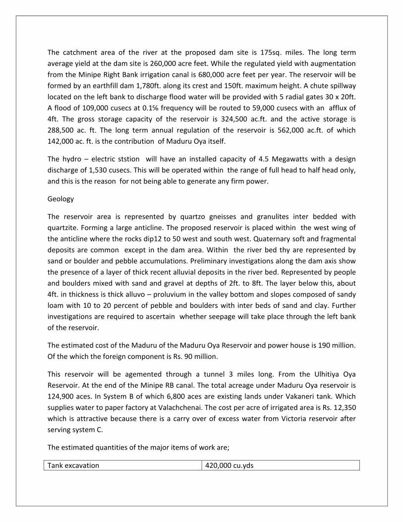
The estimated quantities of the major items of work are;
Tank excavation 420,000 cu.yds
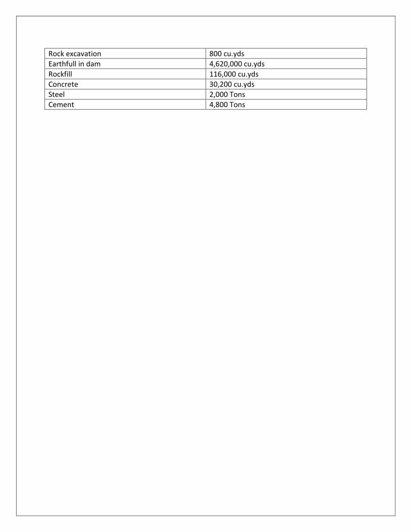
Rock excavation 800 cu.yds
Earthfull in dam 4,620,000 cu.yds
Rockfill 116,000 cu.yds
Concrete 30,200 cu.yds
Steel 2,000 Tons
Cement 4,800 Tons

5. TALDENA HYDRO UNIT Taldena multi – purpose unit provides long term regulation of flow of the Badulu Oya.
Generates electric power and routes the flood peak discharges. The proposed dam site is
located on Badulu Oya 10 miles above the confluence of Badulu Oya with the Mahaweli Ganga.
Where the river flows from a comparatively wide valley through a gorge.
The reservoir will be formed by an earth dam across the main river channel. On a saddle on the
right bank. A chute spillway will be constructed. The spillway will be provided with 5 radial
gates of 30 x 20 feet. The earthen dam will be 1,200 ft. in length along the crest and will have a
maximum height of 200ft. the reservoir will have a gross storage of 66,00 ac.ft. and an active
storage of 56,000 ac. ft.
Average annual regulated water release of the reservoir at 90℅ frequency is 134,000 ac.ft. The
whole of the yield in Taldena reservoir, except for flood water is sent through its Hydro Electric
Station to the Pallewela reservoir on the adjacent Loggal Oya.
The intake of the tunnel is located in the reservoir valley. The tunnel 11,250ft. in length has
diameter of 11ft. A steel penstock is laid along the left bank slopes of the Loggal Oya Valley. The
power house. Which is of the surface type. Will have an installed capacity of 14.5 MW at a
design discharge of 467 cusecs and a head of 433ft. The firm power is 5.4 MW and annual
energy output is 47.6 Million KWH.
There are no direct issues for irrigation from Taldena reservoir. The issues from the reservoir
through the power plant supplement the issues to the irrigation system C and B under the
Ulhitiya Oya and Maduru Oya Reservoirs respectively.
The estimated cost of construction is Rs. 170 million. Of which Rs. 90 million is the local
component and Rs. 80 million the foreign. The allocation for irrigation is Rs. 100 million and for
power Rs. 70 million. The cost per KWH of electrical energy produced is estimated at 8.96 cts.
The quantities of the major items of work to be done are;
Item Unit Quantity
Earth excavation Cu.yd. 133,000
Rock excavation Cu.yd 93,000
Earthfill in dam Cu.yd 1,810,000
Rockfill in dam Cu.yd 3,300
Rock excavation in Tunnel Cu.yd 73,000
Concrete Cu.yd 30,200

Steel Ton 1,090
Cement Ton 4,800
6. RANDENIGALA RESERVOIR PROJECT
6.1 Purpose and Scope
The Randenigala Reservoir is one of four large multipurpose reservoirs in the Master Plan. It is
located on the Mahaweli Ganga. About 13 river miles below the Victoria Reservoir and four
miles above the existing Minipe anicut. It provides long term regulation of flow, generates
electric power and reduces peak flood flows.
The regulated flow from the Victoria Reservoir will be re-regulated by the Rangenigala
Reservoir. This will also control the water supplies to the Minipe Right Bank Canal which is
proposed to be effected directly from the Victoria Reservoir prior to the construction and
commissioning of the Randenigala reservoir. The major purpose of this reservoir, if it is
constructed after Victoria, is to supply the irrigation requirements of 130,300 acs of fields in
Systems D1 and D2 through the proposed Minipe L.B. Canal. These lands are supplied by the
Moragahakanda Reservoir prior to the construction of this reservoir. When the proposed three
reservoirs on the right bank tributaries of the Mahaweli Ganga – the Upper and Lower Uma
Oya and Pallewela reservoirs are constructed and missioner, they will take over part of the
irrigation commitment of Victoria – Randenigala on RB system and the full irrigation
requirements of the fields in systems D1 and D2 will be met by the Randenigala Reservoir with
augmentation from Heen Ganga Reservoir on the Left Bank an a surplus quantity of 110,000 ac.
ft. per year will be available for pumping up to the proposed NCP Canal. The Moragahakanda
Reservoir will then, be switched and regulated exclusively to meet the water requirements
under the proposed NCP canal.
6.2 Location
The Randenigala dam is located across the Mahaweli Ganga, about four miles above the
existing Minipe anicut and is 117.5 miles above the river mouth. It is about 130 miles from
Colombo along existing roads through Kandy, the last four miles from the Minipe anicut being a
jungle track. The nearest railway station is Kandy. And an access roads to the site can be
constructed from the 31st mile of the Kandy – Weragantota road, about 12 miles long, of which
more than 4 miles are existing.

6.3 Basic Features
The total catchment area draining into the reservoir is 900 square miles, of which the drainage
of 730 square miles are intercepted by the Victoria Reservoir. The mean annual run off at the
site is thousand acre feet, including the run – off intercepted by the Victoria Reservoir and the
diversion at Polgolla.
During the UNDP/FAO studies, two alternative proposals for the dam were considered in
cascade with the Victoria Reservoir. The ‘High’ Victoria and ‘Low’ Randenigala combination. As
against the ‘Low’ Victoria and ‘High Randenigala was found more advantageous, and hance the
former combination has been accepted for final studies.
6.4 Dam Reservoirs and Hydropower Stations
The dam is a concrete gravity structure of maximum height 277ft. and 1740f. in length. The
upstream face of the dam has batter of 1;0.075 at the spill section and 1;070 at the other
sections. Pressure release galleries are provided against uplift and for better stability at the
dam base. The selected profile of the dam is stable against sliding and does not develop any
tensile stresses. The spillway is equipped with 3 radial gates 75ft. widex25ft. high. It will rout a
flood of 1000 year frequency with peak discharge 191,000 cusecs to 143,000 cusecs with a
flood lift of 7.6ft. above the normal water surface elevation.
The reservoir will have a total capacity of 629 thousand ac.ft. with an active storage of 374
thousand ac.ft. Operated in cascade with the Victoria Reservoir, it will regulate a flow of 1460
thousand ac.ft. When Kotmale Reservoir is constructed in the upper reaches of the Mahaweli
and commissioned, the regulated flow of this cascade with be reduced to 1390 thousand ac. ft.
The power house is located on the left bank of the river below the dam. The inlet to the power
plant will be though 3 steel penstocks, each 260ft. long and 7.5ft. diameter. The power plant
will consist of three turbo – generators each having a capacity of 25MW. The firm power
developed is 32.1 MW and the annual energy output is 281 million KWH.
6.5 Geology
The geologic structure of the Randenigala dam area on the surface is characterized by quartzo.
Quarzo – feldspathic and quartzo – feldspathic – biotitic gneisses, granulites and crystalline
limestones forming the western arm of a syncline. A bed of crystalline limestone is supposed to
exist at depth of over 3000ft. below the dam axis. Outcrops being seen on the west [upstream]
about ¼ to ½ mile away from the dam axis and in the east about 3 miles downstream, and close
to Minipe. Separate banks of quartzite are to be seen inter bedded among the metasediments.
All the rocks in the area conform to the syncline, whose western arem is overturned at high
elevations of 1500 – 2000ft. above MSL on the dam axis and in the dam site area. Quarternary

soft and fragmented deposits cover the metamorphic rocks almost totally except in steep
scraps or in the river bed itself, when the metamorphic rocks are exposed. The soft and
fragmented deposits have thickness 2 – 12 ft. to 16 – 24ft. at the toe of the hills.
Cost Estimates
The estimated cost of the Randenigala Dam and hydro –electric unit is Rs 700 million including a
foreign component of Rs. 350 million. The allocation for irrigation is Rs. 415 million and for
power Rs. 285 million.
The cost per KWH of energy produced is 10.0 cts. The irrigation system under this reservoir has
to be considered in combination with the LB canal and NCP canal systems. The major items of
work involved are;
Excavation in founds – earth 383,000 cu.yds
Excavation in founds – rock 160,000 cu.yds
Quantity of concrete 1,070,000 cu.yds
Quantity of rockfill 74,000cu.yds
Quantity of earth 75,000 cu.yds
Quantity of cement 163,200 tons
Quantity of Steel 1,760 tons
Quantity of metal structures 4,600 tons

7. UPPER UMA OYA HYDRO UNIT Uma Oya is an important right bank tributary which flows into the Mahaweli Ganga below
Randenigala reservoir. Above the Minipe anicut. Upper Uma Oya multi – purpose unit provides
long term regulation of flow for irrigation and hydro power. Its dam site is located about 15
miles from Badulla, about 2 miles from Hali – Ela – Dambagolla road. The selected site for the
dam is about 18 ¾ miles from its confluence with Mahaweli Ganga, where Uma Oya is confined
in a narrow gorge with steep slopes.
Feldspathic and feldspathic – garnetiferous geneses and granulites are most common in the
reservoir area, less common are quartzon feldspathic and quartzo gneisses with beds of charno
kites and quartzites. The structure of the area is a sharp monocline with a curved strike line of
the roads. The engineering geology and topographical conditions at the site make the
construction of are arch gravity dam possible, and this will be adopted in this project.
The reservoir feet. The dam which is 1,100ft. in length along the crest has a maximum height of
280ft. the spillway of the dam will be provided with 4 radial gates of 60x25ft.
The average annula regulated water release for the purpose of irrigation and power production
is 205,000 ac.ft. The flood flow at the dam site is 163,000 cusecs at 0.1℅ frequency.
The hydro electric station located 3 ½ miles below the dam, is of the surface type. Water is
released to the power house b y a pressure tunnel, 15,000 ft. in length and 7.5ft diameter. The
power house will have an installed capacity of 25.5 MW at a design discharge of 647 cusecs and
a head of 548 feet. The firm power is 10.9 MW and annual energy output is 95.5 million KWH.
The releases from the Upper Uma Oya reservoir will flow down the river for storage and re –
regulation at the Lower Uma Oya reservoir. The releases from Upper Um Oya will be required
to take over part of the irrigation requirements in system B and C. Thus making this quantity of
water available for LB Canal from Randenigala reservoir.
The release from this reservoir will be sent through the Lower Uma Oya reservoir to the RB
Canal irrigation system.
The estimated cost of the Upper Uma Oya reservoir and power house is Rs. 420 million. Of
which Rs. 225 million is allocated to irrigation and the balance to power. The foreign exchange
component of the cost is Rs. 200 million. The cost per KWH of electrical energy s estimated to
be 14.65 cts. The quantities of the major items of work to be done are;
Item Unit Quantity
Earth excavation in foundation Cu.yd 30,000
Rock excavation in foundation
Cu.yd 45,000

Rock excavation in tunnel Cu.yd 25,000
Concrete Cu.yd 370,000
Steel Ton 1,750
Cement Ton 59,200
8. LOWER UMA OYA HYDRO UNIT Lower Uma Oya is a multi – purpose unit. 13 miles below the Upper Uma Oya hydro unit. It
provide regulation of flow on a long term basis. Generates electric power and routs flood
discharges. The dam site is selected 5.7 miles from the mouth of Uma Oya in a deep gorge of
the rive with steep gradient. The reservoir is 28 miles from Badulla and 4 miles from Pallewela.
There is a good road from Badulla to Pallewela, distance about 24 miles. The access to the site
from Pallewela is along a jungle track about 4 miles long.
The estimated long term mean yield at the site from Uma Oya is 447 thousand acre feet. The
dam across the river forms a reservoir of 36 thousand acre feet gross capacity. Its actives
storage on 30,800 acre feet is sufficient for long term regulation. The regulated flow is 317
thousand acre feet. Inclusive of 205 thousand acre feet from Upper Uma Oya reservoir.
Lower Uma Oya hydro unit consists of the following;-
Earth dam of 845 feet along the crest and 175 feet at maximum height.
Chute spillway with a bucket will pass flood water into the river channel. This will be cut in rock.
On the right bank and have 6 radial gates of 30x15ft.
Pressure tunnel driven through fresh and hard monolithic rocks, in the left bank of the Uma Oya
will be 14,000 feet long, with diameter 9 feet.
Hydro electric station will be located on the surface at a distance of 1 mile from the mouth of
Uma Oya.
Installed capacity of Lower Uma Oya hydro electric station is 30 megawatts, at the design head
of 442 feet and discharge of 988 cusecs. Firm power and energy are 12.9 megawatts and 113
million KWH respectively.
Quartzo, quartzo – feldspathic and quartz feldspathic biotite gneisses and granulies with bands
of quarzites form the rocks in the area. The strike o the rocks in N 30 W to N 40 W. The dip
angles are between 25 to 60 North West. The dam site and a greater part of the reservoir area
lie in the North – East dipping arm of an anticline. Whose axis runs in a North Westerly direction
through the fore shores of the proposed reservoir.

Geomorphologically, the Lower Uma Oya reservoir presents favourable conditions against
seepage through the reservoir slopes, except for the fact that, as a result of the zig – zag course
of the river combined with the downstream dips in the rocks, which also include a quartizite
band, seepage may be a factor to be contended with on both flanks of the proposed dam. In
these zones, remedial grouting may be necessary, Detail investigations are necessary during the
final design stage.
Lower Uma Oya hydro unit costs Rs. 260 million of which Rs. 140 million are allocated to
irrigation and Rs. 120 million to power.
The cost per KWH of energy is 10.59 cts.
It will provide together with Upper Uma Oya, a regulated flow of 317,000 ac.ft. of water for
irrigation purposes.
This will take over part of the irrigation commitment under Victoria – Randenigala Reservoir
system. Which will then be available for diversion to the LB Canal and NCP Canal to the North
Central parts of the island.
The quantities in major items of work are;-
Item Unit Quantity
Earth excavation in Dam Cu.yd 295,000
Rock excavation in Dam Cu.yd 381,000
Rock excavation in tunnel Cu.yd 35,000
Earthfill in Dam Cu.yd 178,000
Concrete Cu.yd 13,000
Cement Ton 2,100

9. KALU GANAGA HYDRO UNIT Kalu Ganga hydro unit is an irrigation storage reservoir with a hydro electric station. When does
not produce firm power. This is located on a tributary of the Amban Ganga near Palles on the
15th mile of the Naula – Pallegama tarred road. The nearest rail head is at Matale.
The dam site selected is at mile 9.5 from the mouth of kalu Gange and place where the river is
at its narrowest section, beyond which it spreads into a wide and flat plane. The reservoir will
be formed by an earth fill dam across the river and four other embankments close the saddles,
three on the right bank and one on the left bank. The total length of the dams is a about 1.7
miles and maximum height 165ft.
The reservoir will be of 208,000 acre feet total capacity with an active storage of 188,000 acre
feet. With the average annual yield at the site of 203,00 acre feet. The reservoir will be able to
provide a long term regulation of 172,000 acre feet. The major portion of the regulated flow is
conveyed through the irrigation canal to the Elahera diversion unit.
The Power House has a hydro power unit of 1.9 megawatts installed capacity capable of
generating 772 thousand KWH of hydro electric energy per year. The hydro electric station is
operated from full to half reservoir head only and water is otherwise released through the
irrigation by – passes.
On the right bank saddle adjacent to the river channel, a chute spill is designed. This will contain
four spans with radial gates of 30 x 18ft. A flood peak of 0.1℅ frequency of 65,200 causes will
be routed to 32,400 cusses through the spill.
Geologically, the reservoir area lies in a large syncline, where north south trending axis lies
within the Kalu Ganga valley. Charnockites, quartzo, quartzo – feldspathic and bioties gneisses
and granulities. Limestones [both crystalline and impure] together with occasional bands of
quarzites form the rocks in the area. Quaternary soft and fragmental deposits are developed
practically in all places here. They are thickest in the gently sloped or flat river beds.
Geomorphoogic conditions in the Kalu Ganga reservoir and dam site areas exclude the
possibility of seepage from the reservoir, through the valley slopes and sides, as the proposed
reservoir is surrounded by impervious meterorphic rocks. However, seepage through fractured
and highly weathered zones in the dam area is a possibility and further investigations are
necessary before the final design stage.
Cost of Kalu Ganga hydro unit is Rs. 175 million, the full amount being allocated to irrigation.
The area benefited directly under this reservoir is 8,700 acres in Area F. of which 500 acres are
existing lands irrigated under the Hattota anicut. The surplus water of about 118 thousand ac.
will be available for Elahera area G.

The quantities in major items of work involved are;-
Item Unit Quantity
Earth excavation Cu.yd 406,000
Rock excavation Cu.yd 91,000
Earthfill Cu.yd 5,410,000
Concrete Cu.yd 3,500
Cement Ton 600

10. PALLEWELA HYDRO UNIT Pallewela is a multi – purpose hydro unit on the Loggal Oya. Which provides long term
regulation of flow. Generates electric power and transforms the flood discharges. This is
located on a right bank tributary of the Mahaweli, close to the 18th mile of the Badulla –
Karametiya tarred road. The dam site selected is at mile 7.5 fro the river mouth, just above a
large bend in the river. Pallewela hydro unit forms the lowest pool in a cascade, which
combines the resources of Badullu Oya and Loggal Oya.
The hydro unit consists of the following.
Earthfill dam with a clay centre core having a length along crest of 6,425 feet and maximum
height of 200 feet.
Chute spillway in three steps on the bank to discharge flood waters, consisting four spans with
radial gates of 30 x 20 feet.
Hydro power station has an intake reinforced concrete water way laid through the bottom of
the dam. With steel surge chamber, open penstocks and power house on the surface.
The dam forms a reservoir of gross capacity of 57,000 acre feet, active storage of 46,000 ace
feet and a regulated flow of 268 thousand acre feet when operated in cascade with Taldena
reservoir which has 134 thousand ac. ft. regulated flow.
Installed capacity of Pallewela HES is 10 megawatt with design discharge of 837 cusecs and
head of 166 feet. Firm power is 3.9 megawatts.
Geologically, the reservoir area is in the west wing of an anticline formed by quartz and head of
166 feet. Firm power is 3.9 megawatts.
Geologically, the reservoir area is the west wing of an anticline formed by quartzo and quartzo
feldspathic gneisses inter bedded with quartzites. Crystalline limestone occurs in the south
western periphery of the area.
Alluvo – proluvial deposits are very common in the area. They consist mostly of sandy loam
with inclusions of fragmetal material. Alluvium in the river bed is characterized by sand and
gravel sediments. More seldom by boulder and pebble accumulations.

The proposed reservoir will be under favourable geomorphologic conditions which make
seepage through its slopes impossible. No effective re – working of the reservoir shores and
bottom is expected. The estimated cost of construction of Pallewewa reservoir and power
house is Rs. 230 million of which the foreign component is Rs. 100 million. The allocation for
irrigation is Rs. 195 million and for power is Rs. 35 million. The cost of KWH of energy is 10.2 cts.
The regulated flow will augment the supply of the RB Canal system under Victoria –
Randenigala system. Releasing an equivalent amount of water in the system four use under the
LB Canal/ NCP Canal system.
The quantities of major items of work are;-
Item Unit Quantity
Earth excavation Cu.yd 180,000
Rock excavation Cu.yd 23,700
Earth Cu.yd 81,000
Rockfill Cu.yd 11,000
Concrete Cu.yd 30,000
Steel Ton 462
Cement Ton 4,800

11. HEEN GANGA HYDRO UNIT Heen Ganga is a multi – purpose unit which provides long term regulation of flow, generates
power and routs the flood discharges. This is on a left bank tributary of the Mahaweli, three
miles above the Minipe LB Canal. Matale is the nearest railway station. 70 miles away. The last
12 miles from Pallegama is a dry weather track. The dam site is selected at mile 5.2 from the
river mouth, where that is restricted by a deep and narrow valley, beyond which Heen Ganga
flows through wide and flat country into the Mahaweli.
This hydro unit consists of the following;-
Rock fill dam with an impervious core; 1,060ft. along the crest, 285 feet at maximum height
Chute spill on the left Bank; three spans with redial gates of 30 x 20 feet.
Power House of Heen Ganga HES Located on the left bank below a tunnel. This tunnel if
constructed in advance, can be made use of for diversion and care of the river during
construction.
The regulated flow from this reservoir is 160,000 ac.ft. will be made use of to augment
irrigation supplies under the LB Canal system from Randenigala.
Installed capacity of Heen Ganga HES is 7.1 megawatts, with an average annual energy
production of 25.5 million KWH.
The most common rocks here are quartzo and quartzo – feldspathic gneisses forming small
anticilines and synclines, which strick north. Quanternary soft and fragmental deposits are
found in the area. The geologic section along the dam axis is characterized by quartzo gneisses
with interbeds of quartzo feldspathic gneisses dipping upstream 25 to 45 West.
Preliminary engineering geologic investigations show thick soil composed of modern alluvium
up to a depth of about 15ft. Beneath this layer. There is a layer of alluvo – proluvum and
alluvium up to a depth of about 15ft. Beneath this layer. There is a layer of alluvo – proluvium
and alluvium on valley slopes, about 5-10ft. thick, Next two layers consist of represented by
partly karstic crystalline limestones stones and highly fractured feldspathic garnetiferous
gneisses. The last layer is composed of practically fresh and fresh metasediments dipping 25 to
30 West with ultimate strength from 1500 to 2500kg. per sq. m. these occur in the river bed
below 45ft. and in the valley slopes below 41ft.
The estimated cost of the Heen Ganga reservoir and hydro unit is Rs. 230 million. The allocation
for power is Rs. 30 million. The cost per KWH of energy is 12.9 cts.

The quantities in major items of work are;-
Item Unit Quantity
Earth exaction in dam Cu.yd 200,000
Rock excavation in dam Cu.yd 38,000
Rock excavation tunnel Cu.yd 12,500
Earth fill Cu.yd 720,000
Rockfill Cu.yd 2,000,000
Concrete Cu.yd 19,000
Steel Ton 850
Cement Ton 3,100

12. ROTALAWELA HYDRO UNIT This is the last reservoir on the Mahaweli Ganga, at a point 71 miles from the river mouth. The
access to the site is along the Minipe LB Canal extension, which can be approached from
Pallegama by a cart track, about 25 miles from Pallegama.
The reservoir will have an earth dam of 80 feet at maximum height and 6,720 feet along the
crest. Which has a full capacity of 1956 thousand acre feet with the active storage of 184
thousand acre feet has a regulated flow of 120,000 ac.ft. after construction of the upstream
reservoir. The area inundated by this reservoir is mostly in jungle.
Rotalawela reservoir will re – distribute the local yield inflow from the intercepted catchment of
865 sq. miles below Minipe. The – regulation effect of Rotalawela is to meet the irrigation
requirements in area Kandakadu anicut. A chute spill is proposed on the left bank of the river.
The preliminary geologic investigations have shown that the reservoir area is composed of
different metasediments [gnesses, granulties, quartzites, with interbeds of crystalline
limestones] and mixtogneisses which dip approximately 30 to 40 and covered by alluvo –
proluvial sediments.
The preliminary engineering geologic section along the dam axis shows that the top most layer
extending to a depth of about 20ft. is composed of modern alluvium in the river bed. The
underlying layer of about 30ft. thick alluvo – proluvium composed of salty sand. Partly and
slightly weathered metasediment and mixtogneisses with ultimate strength 700 to 1500 kg/sq
in are found at a depth of about 45ft. further geological investigations are necessary to
determine the actual depth of occurrence of rocks in different places along the dam axis.
The area benefited under this reservoir is 114,000 acres in area A. of which 14,000 acres are
existing lands. The estimated cost is Rs. 130 million.
The quantities in the major items of work involved are;-
Item Unit Quantity
Earth exaction Cu.yd 140,000
Rock excavation Cu.yd 57,000
Earthfill Cu.yd 2,000,000
Concrete Cu.yd 8,000
Cement Ton 1,300

13. KOTMALE PROJECT
13.1 Purpose and Scope
The Kotmale Project envisages the construction of a high dam across the Kotmale Oya, an
important right bank tributary in the upper reaches of the Mahaweli Ganga, about 25 miles
upstream of the Polgolla barrage constructed under Project I of the Master Plan. The Kotmale
project is mainly for the development of hydro power and the regulated discharge from the
reservoir will increase the flow diverted at the Polgolla barrage into the proposed
Moragahakanda reservoir for augmenting the irrigation supplied in systems envisaged in the
Master Plan. The reservoir will also reduce flood peaks and their frequency, thus alleviating the
floods in the Gampola area below it.
13.2 Location
The dam is located at Kotmale across the Kotmale Oya, 4 miles above its confluence with the
Mahaweli Ganga at a place where the river enters a narrow and deep valley with steep banks. It
is close to the Pussellawa – Ulapane highway and is 12 miles from Gampola town, and 88 miles
from Colombo, the nearest is Ulapone, 7 miles away.
13.3 Basic Features
The catchment area of the river at the dam site is 217 square miles, mostly development under
tea plantations. The area that will be submerged by the reservoirs is mostly developed land.
The mean annual run – off at the dam site is 800 thousand ac.ft.
13.4 Dam, Tunnel and Power Station
The dam is a thick earth core rockfill structure, 1972 ft. long and 356ft. maximum height
forming a reservoir of gross capacity of 320,000 ac.ft of active storage of 296,700ft. The
regulated annual flow is 680 thousand ac.ft.
The chute spillway, located on the abutment of the dam is fitted with 4 radial gates 40’ x 46’ –
9. It is designed to deal with a flood of 0.1℅ frequency having a peak discharge of 196,300
cusecs, the corresponding routed discharge being 176,000 cusecs.
The hydro power plant is located under ground and consists of 3 units 50MW each with Francis
turbines operating under a design head of 700ft. the power intake designed for a maximum
discharge of 3000 cusecs is located on the right bank periphery of the reservoir, about 750ft.
above the dam axis. The head race tunnel is of horse – shoe shape 14.5 diameter and 21,700ft.
above the dam axis. The head race tunnel is of horse – shoe shape 14.5 diameter and 21,700ft.
long up to the surge shaft. The surge shaft is 40ft. in diameter and 45ft. high.

The installed capacity of the power plant is 150 MW. The firm power developed is 47.6 MW and
the annual energy output is 411 million KWH.
13.5 Geology
The dam site is located on the crest of an anticline whose axist plunges in North –West
direction at 12 – 14.
The predominant rock at the dam site is charnockite. Which is overlain by soil and boulders and
underlain by limestone. At the dam site exposures of charnockite are found in the left bank
along the road. On the right bank,charnockites along NNE –SSW direction with dips of 10 – 14
towards W-NW.
At the dam site, the depth of hard charnockite varies from 10ft. to 13ft. below ground level on
the left bank. On the right bank between the river bed and elevation 2,400ft. and in the rest of
the area including the river bed the due the to hard rock is 30ft. to 60ft.
Limestones are encountered in the dam site at an average depth of 180 ft. and with an average
cover of 150ft. chanockite, while many of the drill holes in the dam site area have contacted the
limestone, one hole on the dam axis on the left bank had indicated sub – artesian conditions
and the likely cavernous nature of the limestones. This feature warrants suitable treatment of
the dam foundations to guard against the development of foundation pore pressures. The exact
extent and nature of grouting should however be determined by further investigations at the
construction stage.
Geotechnical, the dam site is found suitable both for a gravity concrete/masonry dam or an
earthfill/rockfill dam. An earth/rockfill dam has been preferred from economic considerations.
Construction materials like clay, rock and sand are available in adequate quantitites in the
vicinity of the dam.
13.6 Present Position of Studies
Preliminary investigations and studies were carried out by the UNDP/FAO Teams for the
purpose of preparing the Master Plan of development. The topographical survey prepared
were1;2400 scale survey of dam site; 1;12672 [1’- 16 chs] aerial survey of the reservoir bed and
1;1200 scale survey of the power house area. For the engineering geology studies involved the
drill holes of total depth 8732 linear feet [each between 150 to 400ft.] 21 resistivity points and
521 water absorption tests. Additional investigations were carried out during the period 1971 –
76 under the direction of Water and Power Development Consultancy Services Ltd. [India]. Final
report with specification documents is expected to be ready by end of this year.

13.7 Benefits
In addition to the power benefits, the regulated flow from the reservoir at 90℅ frequency is
680 thousand ac.ft. which increases the quantity of water diverted annually at Polgolla by
250,000 ac.ft. There will be a corresponding reduction in the regulated flow from the regulated
flow from the Victoria – Randenigala cascade by 70 thousand ac.ft. The incease in the power
generated at Polgolla and Moragahakanda will be offset by the reduction at Victoria –
Randenigala cascade.
13.8 Cost Estimates
The estimated coast of construction is Rs. 1035 million. Of which the local component is Rs. 470
million and the balance 565 in foreign component. The allocation for power is Rs. 665 million
and for irrigation Rs. 370 million.
The main items of work involved are;
Earth excavation in dam foundation 370,000 Cu.yds.
Rockfill in dam 5,730,000
Pervious fill in dam 382,000
Semi pervious fill in dam 764,000
Impervious fill in dam 1,305,000
Rock excavation in diversion tunnel chute spill and pressure tunnel 1,191,000
Concrete in diversion tunnel chute spill and pressure tunnel 84,750

14. ULHITIYA OYA RESERVOIR This reservoir is located on the Ulhitiya Oya, a right bank tributary of the Mahaweli Ganga. 10
miles north of the Alutnuwara – Padiyatalawa highway. On its 60th miles from Kandy. It consists
of an earthen dam across the main Ulhitiya Oya and its tributary Ratkinda Oya. Which have a
combined catchment of 109sq. miles. This reservoir has a total capacity of 88,000 ac.ft. which
have a combined catchment of 109sq. miles. This reservoir has a total capacity of 88,000 ac. ft
and an active storage of 61,000 ac. ft. it forms an in tergral part of the R.B. Transbasin canal
which flows into it and saves about nine miles of canal construction. The mean annual yield at
the dam site is 82,700 ac. ft. out of which 45,000 ac. ft. can be regulated by the reservoir. The
total regulated supply from this reservoir with RB canal augmentation consists of 375 thousand
ac. ft. for lands under and 533 thousand ac.ft. to Maduru Oya. The yield of Ratkinda Oya, which
has a catchment of only 12sq. miles has not been considered for the regulated yield of the
combined reservoir.
The earth dam across Ulhitiya Oya is 2M – 4700FT. long and that across Ratkinda Oya is 4000 ft.
long. The maximum heights of fill for the Ulhitiya Oya and Ratkinda Oya dams are 90ft. and 81
ft. respectively.
An open cut, one mile long, is necessary to ling the reservoirs across Ulhitiya Oya and Ratkida
Oya. The bed level of the cut has been fixed at the dead storage level of the combined
reservoir. The spillway for the combined reservoir is located on the right bank end of the
Ulhitiya Oya dam and the cut has been designed to pass the maximum flood of Ratknda Oya.
The 100 – year flood at the dam site 55,300 cusecs, which has been routed through the spillway
to 37,100 cusecs, with a flood lift of 2.5ft. the spillway is a clear over – fall with an agee crest
fitted with five 30.0ft x 15.0ft. radial gates.
Feldspathic biotite gneisses. Granulites and pegmatites with occasional bands of calico gneisses
form the rocks in the reservoir area. Quaternary soft and fragmental deposits are comparatively
thick in the area and consist of loam and sandy loam with a small percentage of pebbles and
boulders. The thickness of solf and fragmental deposits would be about 10 to 15 ft. Rock
outcrops are occasionally seen in the river bed, but are very common on the Monaragala hill on
the right bank. Drilling investigations in the area have indicated the presence of fresh slightly
fractured gneisses at depths of 30 to 40ft. Further investigations are necessary to determine
whether seepage through the reservoir sides, especially through the low ridge on left ridge on
left bank, will take place.
The estimated cost of the Ulhitiya Oya reservoir is Rs. 80 million. The irrigation benefits under
this have to be considered as a part of the RB Canal system under Victoria reservoir, This will be

extended to the adjacent Maduru Oya basin, through a 3 mile long tunnel having a capacity of
850 cusecs.
This reservoir if constructed in advance of the Minipe RB main canal, can irrigate about 10,000
acres of mixed cropping.
The quantities of major items of work to be done are;
Item Unit Quantity
Earth excavation Cu.yd 142,000
Rock excavation Cu.yd 37,000
Earthfill Cu.yd 2,607,000
Concrete Cu.yd 7,300
Steel Ton 200
Cement Ton 1,200

15. RIGHT BANK TRANSBASIN [R.B] CANAL The diversion structure for the R.B. Canal under Victoria Reservoir is sited below the existing
Minipe anicut which already serves the left bank Minipe canal. Initially, the possibility of making
use of the same structure for the right bank canal was considered with a modification of the
anicut. This presents great difficulties in that the R.B. Canal in its first quarter mile has to be
taken through very complicated terrain with steep slopes. To avoid this, a new anicut with crest
level of 372.0 MSL. 500 feet downstream of the existing structure, was designed to provide
better conditions. Both for the diversion structure and the first of the canal. This alternative
proved to be cheaper by about Rs. 500,000. But it major advantage lies in the eaiser conditions
for construction and it is therefore adopted. The new diversion structure will be an anicut [or
weir] across the Mahaweli with a scour sluice in the right flank. The salient features of the
structure are as follows;-
Length of weir, along the crest ---- 680ft
Average Height 10ft.
100 year flood at the site 2,300,000 cusecs
The R.B.Canal is designed to feed irrigation systems C and B. a total area of 200,000 acres. This
canal is designed for 1,250 cusecs with regulation at Ulhitiya and Maduru Oya reservoirs.s
In this reach, four small turnoutswill augment the existing Mapakada. Dambara Wewa and
Sorabora tanks and irrigate lands on the right bank of Loggal Oya. Inlet and outlet structures
have been provided for all level crossings with canal spillways on the upstream of the inlet
structures for emergencies. Suitable drainage under crossings and over crossings have been
allowed for as necessary. The entire reach of the canal is lined with concrete. The estimated
cost of this Transbasin canal is Rs. 445 million.
The quantities in major items of work to be done are;-
Item Unit Quantity
Earth excavation Cu.yd 866,300
Rock excavation Cu.yd 951,000
Earth fill Cu.yd 345,000
Concrete Cu.yd 56,100
Steel Ton 32
Cement Ton 12,900
16. TRANSBASIN CANAL This canal commences from the Left Bank of the Minipe anicut below Randenigala Reservoir
and will take over the irrigation demands of the Left Bank of the Mahaweli basin and also the
irrigation commitments under Moragahakanda on the Amban Ganga. Except Elahera fields,
Moragahakanda will thereafter be switched over to supply the needs of the NCP Canal.
The design of the canal envisages using the existing Minipe anicut and a modification of the
Minipe Yoda Ela upto Heen Ganga. The existing Minipe Yoda Ela irrigates anarrow strip of land
from Minipe between the Yoda Ela and the Mahaweli Ganga, an extent of about 15,200 acres.
The topography of the area is undulating, strewn with rock knob plains. This trace is
undulating, strewn with rock knob plains. This trace is also intercepted by several streams
and rivers, the largest of which are Hassalaka and Heen Ganga where there are existing
crossings, which will have to be modified.
The crest elevation of the elevation of the Minipe anicut is 371.75MSL. It has been proposed
to use this diversion structure without major improvements. The designs provide for
improvements to the present head regulator. The canal has been designed for a maximum
discharge of 1,600 cusecs and it will be augmented from Heen Ganga reservoir; Provision
has been made to pump about 110,000 acre feet annually from it to augment the NCP Canal.
The canal is 90 miles in length and ends at the Kaudulla reservoir. A link canal from Kaudulla
reservoir will be designed to augment the Kantalai tank. Four `siphons have been designed for
the Namini Oya. Amban Ganga, Giritale Oya, Minneriya Oya crossings, the length of which are
1,700ft, and 1,600f. respectively. Turnouts have been provided to augment Parakram Samudra
reservoir, the Girirtale and Minneriya Schemes, the capacities of which are 145 cusec, 35 cusecs
and 100 cusecs respectively. All the streams intercepting the canal trace are provided with level
crossings so that the run – off from these catchments could be absorbed and diverted into the
canal, for which purpose control structures have been provided.
Preliminary geologic investigations have been done for the canal trace in the section between
Minipe and Amban Ganga. The average degree of slope of the alluvo – proluvial plain is 5. On
the surface upto 10 to 30 feet, the most common are quantize deposits of loam and sandy
loam with inclusions of gravel and pebble. Quartzo – feldspathic gnesses and quartzites are
exposed at site. The rocks strike North and dip 15 to 35 West, on an average. Ground water is
commonly found, but the water bearing sandy loams are slightly permeable.

The natural conditions in the reach beyond Amban Ganga to Kaudulla aredifferent.
Geomorphologically, this flat country with local hillocks whose hills and ridges are formed by
quartzo gneisses and granulites. Quartzo feldspathic and charnocktic gneisses and quartizites,
thin beds of crystalline lime stones being of secondary importance. The rocks generally dip
West at an angle 20 to 40.
Quartenary sand loam deposits with inclusion of fragmental material whose thickness is of 10
to 40 feet are more often found. Ground water is confined to the sandy loams at a depth of
10ft. to 20ft.
In the area between Kaudulla and Kantalai, the terrain is flat and slightly rolling and filled
largely with sand sediments and interbred of sandy loam and loam. The thickness the
quaternary deposits vary from 20ft. to 40ft. on an average. Metamorphic rock outcrops are rare
Ground water is a common feature and occurs at a depth of 10 to 20ft. from ground level.
The estimated cost of the L.B. Canal is Rs. 950 million.
The quantities in the major items of work to be done are;-
Item Unit Quantity
Earth excavation Cu.yd 5,543,250
Rock excavation Cu.yd 1,575,950
Earthfill Cu.yd 1,837,650
Concrete Cu.yd 352,450
Steel Ton 965
Cement Ton 88,800

17. NORTH CENTRAL PROVINCE TRANSBASIN CANAL
This canal is required to convey the regulated flow from Moragahakanda to the north central
part of the island, after the Minipe Left Bank Canal from Randenigala takes over the
commitments under Moragahakanda. It starts above Elahera anicut across the Amban Ganga,
runs along the Elahera range of hills and crosses the water divide to enter the Yan Oya basin.
The maximum designed discharge at its take – off will be 2500 cusecs until it reaches of the
canal is 39 ½ Mls. The turnout to Hurulu wewa is designed for a maximum discharge of 144
cusecs.
A closed conduit takes the canal across the Yan Oya and then it runs in deep cutting to cross
the water divide to the Malwatu Oya basin . the length of the canal from the Huruluwewa
turnout to the end is 62 ½ Mls. And its capacity will be 2356 cusecs.
At 43 ¼ after the water divide, the turn out to feed Nachchaduwa, Malwatu Oya Reservoir and
the tanks below it is located. The turnout is designed to discharge 276 cusecs.
The canal trace beyond this point has a capacity of 2080 cusecs and presents little or no
difficulty. Cost estimates provide for the necessary improvements to some minor tanks, which
may have to be retained for regulation of water.
After the Nachchaduwa turnout, there are four other turnouts at 65 M1., 76 ½ M1, 82 ¼ M1.
And 99 ¼ M1, and the canal ends at 103/4 M1. They are designed to feed the proposed
Kapirigama Wewa, Walhalkada Wewa. Kitagala and Kanagarayan Aru reservoir with maximum
discharges of 996 cusecs, 24 cusecs, 816 cusecs and 408 cusecs respectively. The last lap of the
canal from the Kanagarayan Aru turnout to 102 Mls. is designed for a discharge of 340 cusecs
up to the canal from the Kanagarayan Aru turnout to 102 Mls. is designed for a discharge of 340
cusecs up to where the canal bifurcates to feed the proposed Parangi Aru and Pali Aru
reservoirs. The slope of the land falls rapidly after the 70th Mile of the canal and the gradient
has also been suitably increased beyond this point.
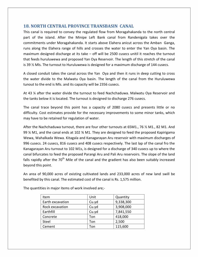
18. NORTH CENTRAL PROVINCE TRANSBASIN CANAL This canal is required to convey the regulated flow from Moragahakanda to the north central
part of the island. After the Minipe Left Bank canal from Randenigala takes over the
commitments under Moragahakanda. It starts above Elahera anicut across the Amban Ganga,
runs along the Elahera range of hills and crosses the water to enter the Yan Oya basin. The
maximum designed discharge at its take – off will be 2500 cusecs unitil it reaches the turnout
that feeds huruluwewa and proposed Yan Oya Reservoir. The length of this stretch of the canal
is 39 ½ Mls. The turnout to Huruluwewa is designed for a maximum discharge of 144 cusecs.
A closed conduit takes the canal across the Yan Oya and then it runs in deep cutting to cross
the water divide to the Malwatu Oya basin. The length of the canal from the Huruluwewa
tunout to the end is Mls. and its capacity will be 2356 cusecs.
At 43 ¼ after the water divide the turnout to feed Nachchaduwa. Malwatu Oya Reservoir and
the tanks below it is located. The turnout is designed to discharge 276 cusecs.
The canal trace beyond this point has a capacity of 2080 cusecs and presents little or no
difficulty. Cost estimates provide for the necessary improvements to some minor tanks, which
may have to be retained for regulation of water.
After the Nachchaduwa turnout, there are four other turnouts at 65M1., 76 ½ M1., 82 M1. And
99 ¼ M1, and the canal ends at 102 ¾ M1. They are designed to feed the proposed Kapirigama
Wewa, Wahalkada Wewa. Kitagala and Kanagarayan Aru reservoir with maximum discharges of
996 cusecs. 24 cusecs, 816 cusecs and 408 cusecs respectively. The last lap of the canal fro the
Kanagarayan Aru turnout to 102 M1s, is designed for a discharge of 340 cusecs up to where the
canal bifurcates to feed the proposed Parangi Aru and Pali Aru reservoirs. The slope of the land
falls rapidly after the 70th Mile of the canal and the gradient has also been suitably increased
beyond this point.
An area of 90,000 acres of existing cultivated lands and 233,000 acres of new land swill be
benefited by this canal. The estimated cost of the canal is Rs. 1,575 million.
The quantities in major items of work involved are;-
Item Unit Quantity
Earth excavation Cu.yd 9,338,300
Rock excavation Cu.yd 3,908,000
Earthfill Cu.yd 7,841,550
Concrete Ton 418,000
Steel Ton 2,500
Cement Ton 115,600

The canal will supply water to the fields through the existing major tanks and the seven service
reservoirs under it. The service reservoir, namely Malwattu Oya, Yan Oya, Kapirigama,
Kitalagala. Kanagarayan Aru. Pali Aru and Parangi Aru situated in the five major river basins in
the area, will have a combined capacity of about 1.2 Million acre feet.

19. MALWATTU OYA RESERVOIR The proposed Malwattu Oya reservoir is across Malwattu Oya, which is the second largest river
basin in Sri Lanka, and is in the Dry Zone. The site is located 108 miles from Kandy and 12 miles
from Medawachchiya which is the nearest town accessible by gravel road from Chedidkulam on
the Medawachchiya – Manner tank road. Cheddikulam is the closest railway station. 5 miles
from the site.
The total catchment area of the river at the dam site is 819 sq. miles. There are nine major
irrigation tanks in the catchment are which intercept 491 sq. miles. The long term mean annual
yield at the dam site is 308.8 thousand acre feet. The proposed dam has a length of 15,000ft.
and a maximum height of 90ft. The reservoir will have a gross storage capacity of 225,000 ac. ft.
and an active storage of 220,000 ac.ft. Malwattu Oya water is presently diverted by an anicut
at Tekkam below the proposed site to supply water fileds under the Giant’s tank and
Akathimurippu on the left bank. The storage at Malwattu Oya reservoir will regulate the
supplies to the fields under these two tanks. In extent of 19,300 acres. Malwattu Oya
augmented by the supplies from NCP Canal will benefit 16,300 acres of new lands in addition to
19,300 acres of existing lands. However, in the first stage till the NCP Canal is constructed. It is
proposed to irrigate only 9,000 acres of new lands and provide additional benefits to 19,300
acres of existing fields in irriation systems below it.
This reservoir together with Kapirigama reservoir, also situated in the Malwattu Oya basin , will
benefit 52,200 acres of existing fields and 87,800 acres of new lands after augmentation from
the NCP Canal. The feasibility studies of the Malwattu Oya reservoir were carried out by a team
of Soivet engineers [USSR] is 1959 /60 and a feasibility report has been prepared for the
construction of this reservoir, utilizing the natural yield of the river. This will have to be revised
for operating with augmentation from the NCP Canal. There is a possibility of developing hydro
power which may not be firm power.
The estimated cost of the reservoir is Rs. 915 million . of which the foreign component is about
Rs. 75 million.
The quantities in major items of work are
Item Unit Quantity
Earth excavation Cu.yd 460,000
Rock excavation Cu.yd 280,000
Earth fill Cu.yd 4,808,000
Concrete Cu.yd 63,700
Steel Ton 6
Cement Ton 12,740

20. YAN OYA RESERVOIR This reservoir is across Yan Oya located about 31 miles from Horawapotana which is the nearest
town and about 7 miles from Gomarakadawela which is the nearest village. The access is from
Pankulam [on the 18th mile of the Trincomalee Anuradhapura road] through Gomarakadawela
and Pangurugaswewa. A distance of about 12 miles. The last two miles being a foot path.
The catchment area of the river at the dam site is 506Sq. Miles. The long term mean inflow in
the river is 283.9 thousand acre feet. The earth dam which is 12,000 ft. has a maximum height
of 90ft. The gross storage of the reservoir is 208 thousand acre feet. The Yan Oya reservoir is
to be fed by the NCP Canal, from a turn out in the 40th mile of the canal. The turn out is
designed for a maximum discharge of 144 cusecs.
The Yan Oya reservoir will provide irrigated facilities to 3,000 acres of existing fields 24,900
acres of new lands. Till the NCP canal is constructed, utilizing only the natural yield in the river,
the reservoir can irrigate 16,500 acres of new lands in addition to the existing fields.
The estimated cost of the Yan Oya reservoir is Rs. 170 Million, of which Rs. 65 million is the
foreign component.
21. OTHER SERVICE RESEROIRS UNDER THE N.C.P. CANAL There are five other service reservoirs which would be augmented by the NCP Canal. They are;
Kapirigama Reservoir
This is constructed across a tributary of Malwathu Oya and is located about 18 miles from
Anurdhapura and about 6 miles from Seepukulama.
The catchment area of the stream at the selected site being only 13sq. miles, the reservoir will
depend mainly on the issues from the NCP Canal to irrigate the lands under it.
The earth dam which creates the reservoir is 15,200ft. in length and has a maximum height of
80 ft. It has a gross storage of 74,000ac. ft. and an active storage of 71,000 ac.ft. The extent

benefitted is 79,890 acress of new lands and 22,940 acres existing lands in System 1 with
augmentation from the NCP Canal.
21.2 Kitagala Reservoir
The Kitagala reservoir is located about 6 miles from Heart - Halmillewa which is about 10 miles
along Kebitigollawa – Pulmoddai road. The nearest railway station is Vavuniya. The reservoir is
formed by constructing an earth dam across a tributary of Ma Oya.
The river is 20,300 acre feet. The dam is 15,000ft. and has a maximum height of 115ft. The
reservoir has a gross storage of 180,000 acre feet and an active storage of 172,000ac.ft. It will
provide water to irrigate 76,500 acs. Of new lands and 19,900 acs. Of existing fields in system L.
21.3 Kanagarayan Aru Reservoir
The Kanagarayan Aru Reservoir which is formed by constructing an earth dam across
Kanagarayan Aru is located about 16 miles from Vavuniya and is about 1 mile from
Puliyankulama. Along Puliyankulama - Mullativu road. The nearest railway station is
Puliyankulama.
The river has a catchment area of 33sq. miles at the dam and the long term mean annual yield
is 10,730ac.ft. The dam has a length of 11,000 ft, and a maximum height of 85ft. the reservoir
has a gross storage of 112,000 ac.ft.and an active strage of 110,000 ac.ft. It will Provide water
to 20,000 acs. In system K. of which 600 acs. Are of existing fields with augmentation from the
NCP Canal.
21.4 Parangi Aru Reservoir
This Reservoir formed across Parangi Aru is located about 16 miles from Mankulam which is the
closest town. From where access is available to the site a long a jeep track.

The Parangi Aru has catchment area of 165sq. miles at the selected dam site.the earth dam
which forms the reservoir has a length of 20,000ft. and maximum height of 95ft. the gross
storage of the reservoir is 285,000 ac.ft. and an active storage of 279,000 ac.ft. The reservoir
will provide water to irrigate 1,000 acres of existing fields and 16,800 acres of new lands in
System J. When augmented by the NCP Canal.
21.5 Pali Aru Reservoir
This reservoir constructed across Pali Aru is located about 8 miles from the 136th mile along
Kandy Jaffna road. The nearest town and railway station is at Puliyankulam from where where
there is a jeep track.
The river has a catchment area of 35sq. miles at the selected dam site. The natural yield being
small. The reservoir depends mainly on issues from NCP canal. The dam has a length of
15,000ft. and a maximum height of 115ft. the reservoir which has a gross storage of 180,000 ac.
ft. and an active storage of 172,000 ac.ft. provides water 8,000 acres of land in system J. of this
6,100 acres are ex-sisting fields.